5
Assessment and Retrofit of Masonry Structures 113 Figure 3.9 ASCE 41 retrofit evaluation process (adapted from Ref. 3.38).
Assessment and Retrofit of Masonry Structures 113
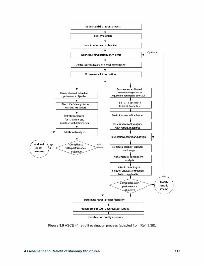
Figure 3.9 ASCE 41 retrofit evaluation process (adapted from Ref. 3.38).
158 Site Investigation and Analysis Chapter 4
(a) Near-surface bar (b) Bar at depth (c) Large metal inclusion
Figure 4.29 Interpreting pachometer readings.
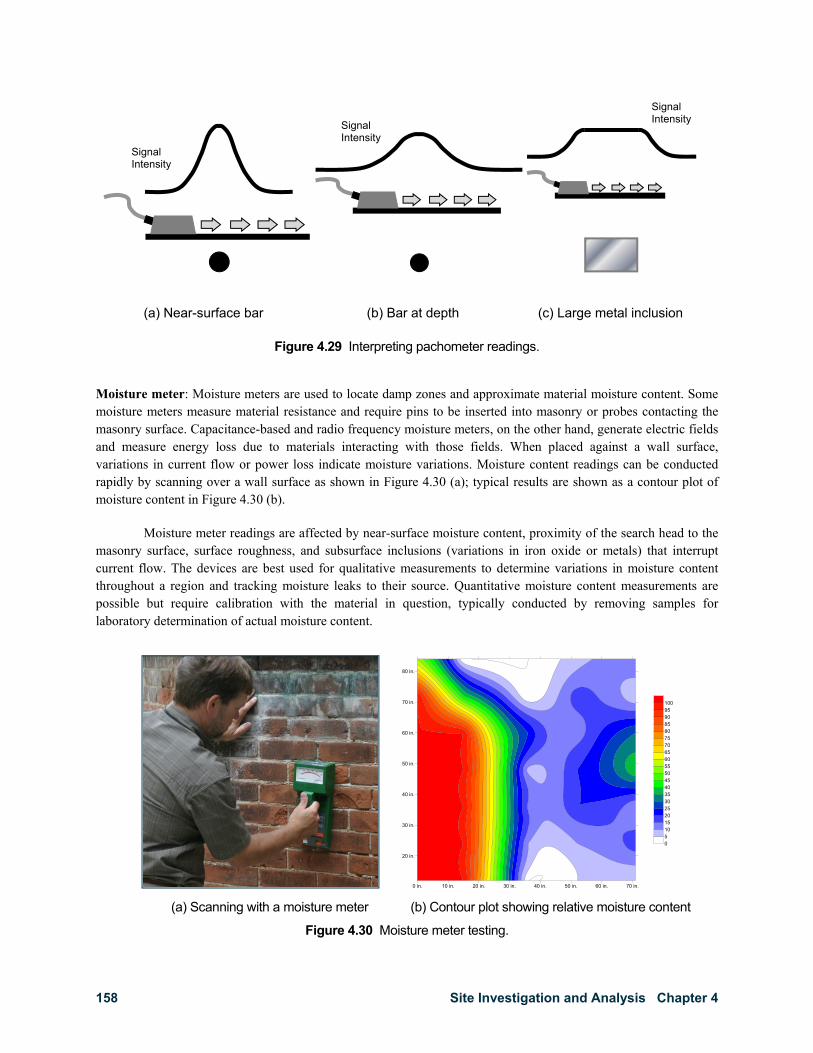
Moisture meter: Moisture meters are used to locate damp zones and approximate material moisture content. Some moisture meters measure material resistance and require pins to be inserted into masonry or probes contacting the masonry surface. Capacitance-based and radio frequency moisture meters, on the other hand, generate electric fields and measure energy loss due to materials interacting with those fields. When placed against a wall surface, variations in current flow or power loss indicate moisture variations. Moisture content readings can be conducted rapidly by scanning over a wall surface as shown in Figure 4.30 (a); typical results are shown as a contour plot of moisture content in Figure 4.30 (b).
Moisture meter readings are affected by near-surface moisture content, proximity of the search head to the masonry surface, surface roughness, and subsurface inclusions (variations in iron oxide or metals) that interrupt current flow. The devices are best used for qualitative measurements to determine variations in moisture content throughout a region and tracking moisture leaks to their source. Quantitative moisture content measurements are possible but require calibration with the material in question, typically conducted by removing samples for laboratory determination of actual moisture content.
(a) Scanning with a moisture meter (b) Contour plot showing relative moisture content
Figure 4.30 Moisture meter testing.
0 in. 10 in. 20 in. 30 in. 40 in. 50 in. 60 in. 70 in.
20 in.
30 in.
40 in.
50 in.
60 in.
70 in.
80 in.
05101520253035404550556065707580859095100
Signal Intensity
Signal Intensity
Signal Intensity
Assessment and Retrofit of Masonry Structures 165
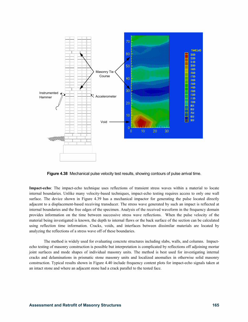
Figure 4.38 Mechanical pulse velocity test results, showing contours of pulse arrival time.
Impact-echo: The impact-echo technique uses reflections of transient stress waves within a material to locate internal boundaries. Unlike many velocity-based techniques, impact-echo testing requires access to only one wall surface. The device shown in Figure 4.39 has a mechanical impactor for generating the pulse located directly adjacent to a displacement-based receiving transducer. The stress wave generated by such an impact is reflected at internal boundaries and the free edges of the specimen. Analysis of the received waveform in the frequency domain provides information on the time between successive stress wave reflections. When the pulse velocity of the material being investigated is known, the depth to internal flaws or the back surface of the section can be calculated using reflection time information. Cracks, voids, and interfaces between dissimilar materials are located by analyzing the reflections of a stress wave off of these boundaries.
The method is widely used for evaluating concrete structures including slabs, walls, and columns. Impact-echo testing of masonry construction is possible but interpretation is complicated by reflections off adjoining mortar joint surfaces and mode shapes of individual masonry units. The method is best used for investigating internal cracks and delaminations in prismatic stone masonry units and localized anomalies in otherwise solid masonry construction. Typical results shown in Figure 4.40 include frequency content plots for impact-echo signals taken at an intact stone and where an adjacent stone had a crack parallel to the tested face.
Masonry Tie Course
Instrumented Hammer Accelerometer
Void
240 Retrofit Chapter 5
(a) Diagonal braces (b) Steel strongback
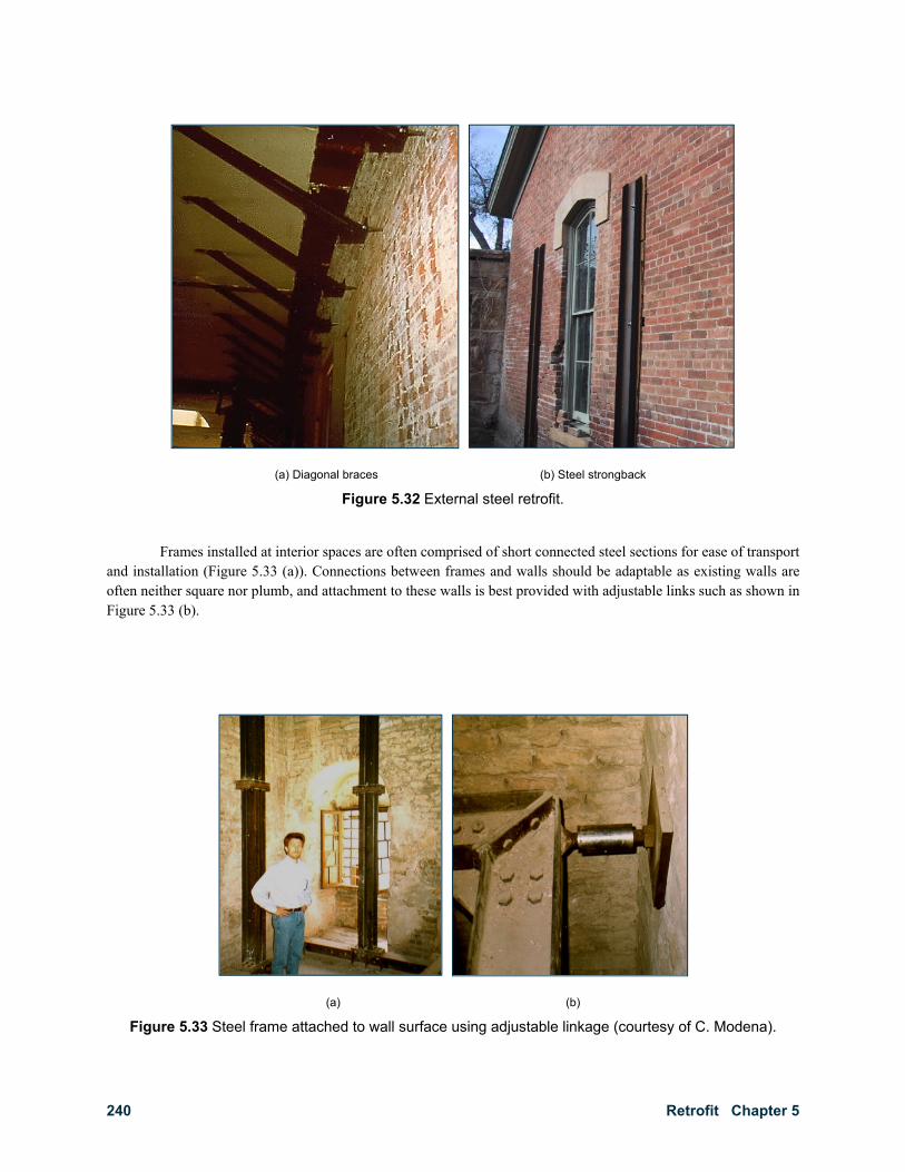
Figure 5.32 External steel retrofit.
Frames installed at interior spaces are often comprised of short connected steel sections for ease of transport and installation (Figure 5.33 (a)). Connections between frames and walls should be adaptable as existing walls are often neither square nor plumb, and attachment to these walls is best provided with adjustable links such as shown in Figure 5.33 (b).
(a) (b)
Figure 5.33 Steel frame attached to wall surface using adjustable linkage (courtesy of C. Modena).
Assessment and Retrofit of Masonry Structures 243
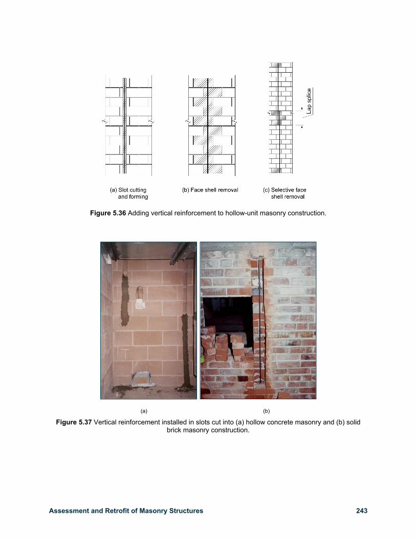
Figure 5.36 Adding vertical reinforcement to hollow-unit masonry construction.
(a) (b)
Figure 5.37 Vertical reinforcement installed in slots cut into (a) hollow concrete masonry and (b) solid brick masonry construction.


