NASA AVSCOM Technical Memorandur) 100290 Technical Memorandum 88-C-001 ' Assessment, Development, and Application of Combustor Aerothermal Models J.D. Holdeman National Aeronautics and Space Administration Lewis Researci, Center Cleveland, Ohio H.C. Mongia Allison Gas Turbine Division General Motors Corporation Indianapolis, Indiana BEST and AVAILABLE COPY E.J. Mularz Propulsion Directorate U.S. Arnv A viation Ehsearch and Technology Activity-AVSCOM Lewis Research Cenit r Cleveland, Ohio Prepared for the 33rd lntcri,Lonal Gas Turbine and Aeroengine Congress and Exposition sponsored by the American Society of Mechanical Engineers Amsterdam. The Netherlands, June 5-9, 1988 07 I 8 8 II 28 0O'7
Transcript
NASA AVSCOMTechnical Memorandur) 100290 Technical Memorandum 88-C-001
' Assessment, Development, and Applicationof Combustor Aerothermal Models
J.D. HoldemanNational Aeronautics and Space AdministrationLewis Researci, CenterCleveland, Ohio
H.C. MongiaAllison Gas Turbine DivisionGeneral Motors CorporationIndianapolis, Indiana BESTand AVAILABLE COPY
E.J. MularzPropulsion DirectorateU.S. Arnv A viation Ehsearch and Technology Activity-AVSCOMLewis Research Cenit rCleveland, Ohio
Prepared for the33rd lntcri,Lonal Gas Turbine and Aeroengine Congress and Expositionsponsored by the American Society of Mechanical EngineersAmsterdam. The Netherlands, June 5-9, 1988
07I 8 8 II 28 0O'7
Accession For111-I r ASSESSMENT, DEVELOPMENT, AND APPLICATION OF COMBUSTCR AEROTHERMAL MODELS
NTIS GRA&I XDTIC TAB 13 1 J.D. HoldemanD B National Aeronautics and Space Administration
Us oaoe 1 Natonal Lewis Research CenterJustlfiOtiOn Cleveland, Ohio 4435 D T IC
Allison Gas Turbine Division
Distribution/ General Motors CorporationIndianapolis, Indiana S joV 0
Avail and/or E.J MularzDist Special UIS. Army Aviation and Technology Activity AVSCOM -La a et NASA Lewis Research Center
Cleveland, Ohio 44135
Empirically based procedures have led to success-Tful evolutionary combustor improvements. However, as
he gas turbine combustion system design and these methods are experience-based, they are not welldevelopment effort is an engineering exercise to obtain suited when combustor design requirement are signif-an acceptable solution to the conflicting design trade- icantly different from that of current technologyoffs between: combustion efficiency, gaseous emis- engines. The rapidly developing CFD (Computationalsions, smoke, ignition, restart, lean blowout, burner Fluid Dynamics) capability is providing an additional,
exit temperature quality, structural durability, and tool in the design process which can have a powerfullire cycle cost. For many years, these combustor positive influence on future design canahility. Indesign trade-offs have been carried out with the help these codes, combustion system subcomponents includingof fundamental reasoning and extensive component and diffusers, fuel injectors, and combustor liners, inbench testing, backed by empirical and experience addition to the complex internal flow, need to be accu-correlations. rately modelled. To achieve this, physical sub-models
Recent advances in the capability of computational and accurate numerical schemes must be developed tofluid dynamics (CFD) codes have led to their applica- describe the various aerothermochemical p-ocessestion to complex three-dimensional flows such as those occurring within the combustion chamber.in the gas turbine combustor. A number of U.S. Govern- A number of U.S. Government and company sponsoredment and industry sponsored programs have made signifi- programs have made significant contributions to thecant contributions to the formulation, development, formulation, development, and verification of anand verification of an analytical combustor design analytical combustor design methodology. These havemethodology which will better define the aerothermal included: U.S. Army Combustor Design Criteria Valida-loads in a combustor, and be a valuable tool for design tion (Bruce et al., 1979; Mongia et al., 1979, Mongiaof future combustion systems. The contributions made and Reynolds, 1979), NASA Swirling Recirculating Flowby NASA Hot Section Technology (HOST) sponsored Aero- (Srinivasan and Mongia, 1980), NASA Soot and NOx Emis-thermal Modeling and supporting programs are described sions Prediction (Srrvatsa, 1980), NASA Primary Zonein this paper. , Study (Sullivan et al., 1983), NASA Mass and Momentum
Transfer (Johnson and Bennett, 1981; Roback andINTRODUCTION _'.#,A Johnson. 1983; Johnson et al., 1984), NASA Lateral Jet
Injection (Lilley, 1986; Ferrell and Lilley, 1985;The goal of gas turbine combustion system design McMurray and Lilley, 1986; Ong and Lilley, 1986), NASA
and deve'opment is to obtain an acceptable solution to Dilution Jet Mixing (Srinivasan et al., 1982, 1984,the conflicting design trade-offs between combustion 1985; Sr inivasan and White, 1986, Holdeman et al.,efficiency, gaseous emissions, smoke, ignition, 1984; Holdeman and Srinivasan, 1986; Holdeman et al..restart, lean blowout, burner exit temperature quality, 1987a), NASA Transition Mixing Study (Reynolds andstructural durability, and life cycle cost. For many White, 1986; Holdeman et al., 1987b), NASA HOST Aero-years, these combustor design trade-offs have been car- thermal Modeling (Kenworthy et al., 1983; Sturgess,ied out with the help of fundamental reasoning and 1983; Srinivasan et al., 1983a, 1983b), NASA Error
extensive component and bench testing, backed by empir- Reduction (Syed et al., 1985), industry IR & D pro-Ical and experience correlations. The ultimate goal grams, and advanced combustor development programs.has been to develop a reliable combustor design system The NASA Hot Section Technology (HOST) Combustionthat can provide quantitatively accurate predictions Program has supported several of these co)grams. Theof the complex combustion flow field characteristics overall ohiectiva of the H r1fnmhitirn Projec 'c
3 so li,' an optimum comoustio, system design develop and verify advanced aralytical methods tocan be achieved within reasonable cost and schedule ioipuve the capab'iity to design combustion systemsconstraints.
1G im iel i Il lgsl~n md now.~ a26
for advanced aircraft gas turbine engines. This objec- (4) give quantitatively unsatisfactory
tive is being approached both computationally and correlation with data for complex swirlingexperimentally, flows with recirculation zones
Computationally, HOST first sponsored studies to (5) give quantitatively unsatisfactoryassess and evaluate the capabilities of existing correlation, but predict trends correctly, for
aerothermal models (circa 1982). Based on the results complex three-dimensional flows.of these assessments and other studies in the liter-ature, HOST supported several studies to develop new Algebraic Stress Model and Its Modificationsand improved numerical methods for the analysis of tur- Mean flow predictions with this model agreed withbulent viscous recirculating flows, with emphasis on the data as well as the k-c model results, thereforeaccuracy and speed of solution, the conclusions above also apply to this model. In
The objectives of HOST sponsored eyperimental addition, the Algebraic Stress Model gives reasonablestudies were to improve understanding of the flow phys- predictions for the Reynolds stress components, con-ics and chemistry in constituent flows, and to obtain sistent with the strengths and limitations of the k-cfully-specified, benchmark-quality experimental data models (Mongia et al., 1986).
suitable for the assessment of the capabilities of The results of standard k-c and algebraic and dif-advanced computational codes. ferential Reynolds stress turbulence models, have been
This paper reviews the advances in the compared in several continuing assessment studies. Anstate-of-th2-art in combustor aerothermal modeling, example comparison (Mongia, 1987) of data and calcula-while highlighting the programs supported by the HOST tions using a hybrid/SIMPLE numerical scheme is shownProject (Turbine Engine Hot Section Technology, 1982, In Fig. 3. This flow is that of co-annular turbulent19 3, IQ84, 1985, 1986, 1937). Due tc !'L yLh l'mita- jets flowing into an axisymmetric sudden expansiontions not all programs that received HOST support are (Roback and Johnson, 1983). In this figure, velocityincluded, and, for completeness, some programs that profiles are shown at downstream, distance from 0.11made a significant contribution, but which did not to 2.5 pipe diameters from the expansion.
draw their primary support from HOST are discussed. Scalar Transport Model
AEROTHERMAL MODELING ASSESSMENT Mongia et al., (1986) reported that the k-c modelwith specified Prandtl number predicts scalar fluxes
Gas turbine combustion models include submodels reasonably well for flow where the gradient diffusionof turbulence, chemical kinetics, turbulence/chemistry approximation is valid. An alternative, the algebraicinteraction, spray dynamics, evaporation/combustion, scalar transport model, has the capability to improveradiation, and soot formation and oxidation. A very predictions over the k-c approach, but further work isextensive assessment of numerics, physical submodels, needed to establish its validity for swirling recircu-and the suitability of the available data was made by lating flows.
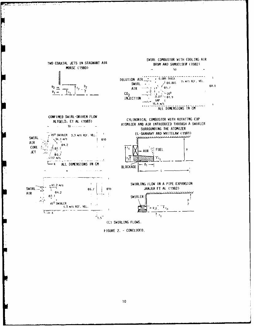
three contractors under Phase 1 of the HOST AerothermalModeling program (Kenworthy et al., 1983; Sturgess, Turbulence/Chemistry Interaction Models1983; Srinivasan et al., 1983a, 1983b). These investi- It was also concluded by Mongia et al., (1986)gations surveyed and assessed current models and iden- that both 2- and 4-step reaction schemes showed prom-tified model deficiencies through comparison between Ise for application in gas turbine combustors, butcalculated and measured quantities. Results of the need to be further validled agrinst data f-em simpieassessment by Srinivasan et al., (1983a, 1983b) are flames. The modified eddy breakup model predictedsummarized by Mongia et al. (1986). The constituent trends well, and it was recommended that it should beflows examined included: (1) simple flows with no pursued because this approach could be easily extendedstreamline curvature, (2) compleA flows without swirl, to multistep kinetic schemes.and (3) complex flows with swirl. Geometries forseveral test cases from each of these categories are Numerical Accuracyshown in Fig. 2. A significant deficiency identified in the assess-
ments was that for many flows of interest the accuracyk-c Turbulence Model of the calculation was limited by the numerical approx-
The k-c model is the simplest turbulence model imations, wherein the false diffusion is of the samethat is suitable for recirculating flow calculations, order of magnitude as the turbulent diffusion. ThisThis model achieves closure by using a gradient trans- masked the differences between turbulence models suchport model for Reynolds stress with an isotropic eddy that very different models gave essentially the sameviscosity. For flows where the isotropic eddy vis- result, and sometimes resulted in undeservedly goodcosity assumption is not valid, the k-c model may be agreement between data and predictions.either modified (e.g. low Reynolds number correction, If false diffusion is present, the numeical solu-Richardson number correction) or replaced with an alge- tion obtained for any given flow depends on the gridbraic or differential Reynolds stress model, density and distribution. An example of the compari-
Assessment of the k-c model(s) of turbulence sons made in the assessment program is given by theshowed that these models: comparison in Figs. 4 and 5 between measured and calcu-
(1) require low Reynolds Number correction for lated temperature distributions downstream from a rowpredicting wall shear flows, and streamline of jets entering a confined crossflow. This flow is acurvature modifications for accurately constituent flow in most gas turbine combustors, andpredicting curved boundary layers has been treated extensively in the literature, includ-
(2) give quantitatively good correlation with ing the recently completed NASA Dilution Jet Mixingdata for simple flows and non-recirculating program, from which data were compared with three-swirling flows dimensiznal calcuiations in the Phase I assessment
(3) give ,uantittvely reasjiiadle results for study by Srinivasan et al., (1983).nonswirling recirculating flows
2
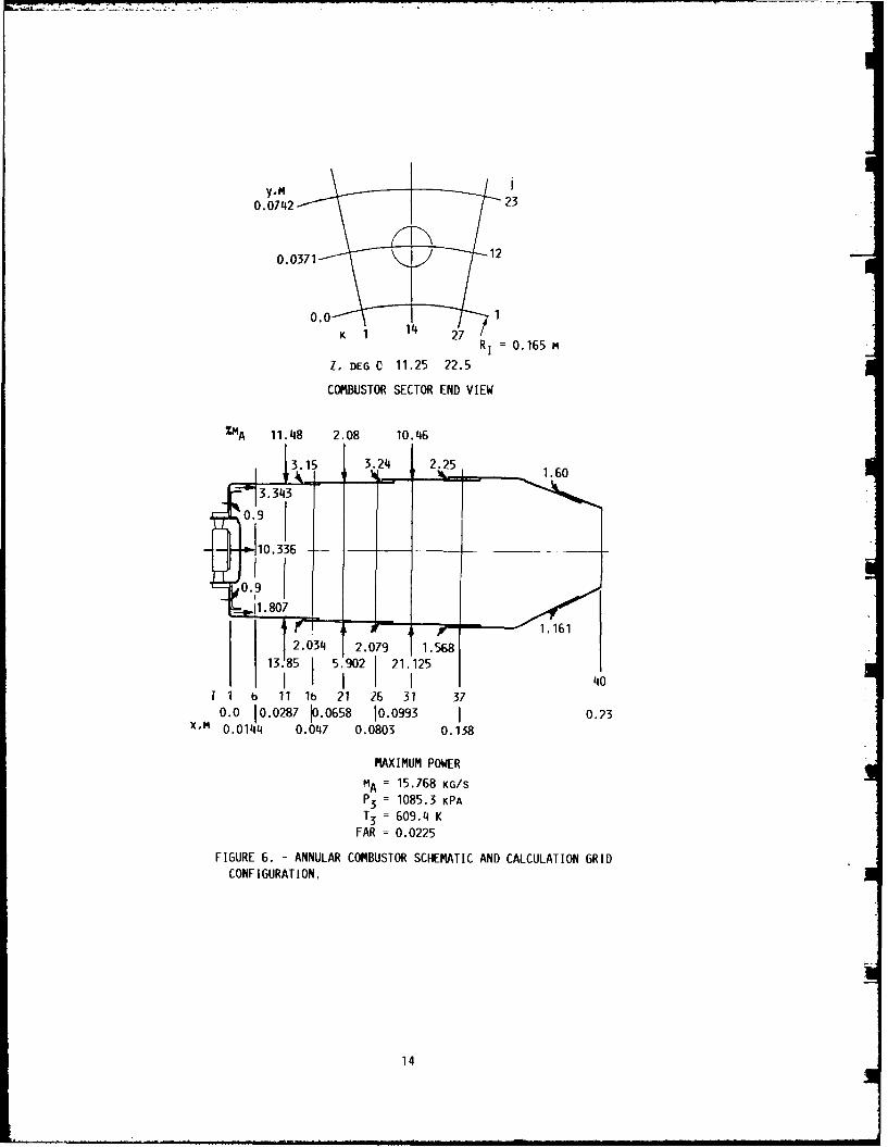
The calculated and experimental results shown are performance parameters of interest. That is, flowfor a single row of jets with an orifice spacing to field and geometric parameters that are needed in thediameter ratio, S/D, = 2 injected into a ducted main- empirical equations, such as combustion volume and thestream with a duct height to orifice diameter ratio fraction of air participating in the primary combustionHID, - 8. The jet-to-mainstream momentum flux ratio, reaction, are provided by the analytical calculations.3. for this test was 25.32. Calculations for this Satisfactory agreement with experimental data hascase made with 45x26x17 (19890) nodes, are shown in been shown (Rizk and Mongia, 1986) for emissions, per-Fig. 4. The parameter plotted in these figures is the formance and heat transfer. Tne combustor for whichdimensionless mean temperature difference ratio, THETA, data were available, and for which calculations werewhere THETA = (Tm - T)/(Tm - Tj). The predicted jet performed, is shown schematically in Fig. 6. A typi-penetration and mixing are less than that shown by the cal comparison between data and predictions for CO,data. unburned hydrocarbons, NOx, soot emissions, combustion
The calculation shown in Fig. 4 used 49 nodes to efficiency, pattern factor, and lean blowout are shownsimulate each jet. It is generally not possible to use in Figs. 7(a) to (g) respectively. The model is inthis many grid points in such a small region; as few good agreement with the data over the entire sea-levelas four may be used in practice for each jet. To simu- engine operating range. Calculated liner wall tempera-late the accuracy of this approximation, calculations tures for both the inner and outer walls of this com-were performed for the same flow and geometric condi- bustor are shown in Fig. 8 for three typical z-planestions, but with a 27x26x8 (5615) grid. These coarse- along k = 5, 14, and 23. Here k denotes nodalgrid calculations (Fig. 5) are in much better agreement planes along the combustor circumferential direction.with the data than the fine-grid calculations. These Although no direct comparison with liner wall tempera-and other calculations In Srinivasan et al., (1983b) ture data was made, the predictions look reasonable.clearly demonstrated that the three-dimensional calcu-lations were not grid independent. AEROTHERMAL MODELING PHASE II
Conclusions from the Assessments Based on the recommendations of the Phase IThe major conclusion in the HOST Aerothermal assessment studies, activities in Phase II of the HOST
Modeling Phase I assessment studies by Kenworthy Aerothermal Modeling program concentrated on developinget al. (1983), Sturgess (1983), and Srinivasan et al. improved numerical schemes, and collecting completely-(1983a, 1983b) was that the available computational specified data for nonreacting single and two-phacefluid dynamics (CFD) codes provided a useful combustor swirling and nonswirling flows. The programs initiateddesign tool. Although significant advances have been were: Improved Numerical Methods; Flow Interactionmade in the development and validation of multidimen- Experiment; and Fuel Injector/Air Swirl Ch~kracteriza-slonal gas turbine combustion calculation procedures, tion. The first of these is a prerequisite to furtherthe codes assessed were only qualitatively accurate, model development, and the data obtained in the latterespecially for complex three-dimensional flows, and two studies will be used to validate advanced modelsfurther work was needed. It was concluded that both a being developed independently.significantly improved numerical scheme and fully-specified experimental data (i.e. both mean and turbu- Improved Numerical Methodslence flowfield quantities, with measured boundary The hybrid finite differencing scheme employed inconditions) for complex non-reacting and reacting generally available combustor codes gives excessiveconstituent flows were needed before various emerging numerical diffusion errors which preclude accuratephysical sub-models of turbulence, chemistry, sprays, quantitative calculations. In response to this defi-turbulence/chemistry interactions, soot formation/ ciency, HOST supported three programs with the primaryoxidation, radiation, and heat transfer could be prop- objective to identify, assess, and implement improvederly assessed. solution algorithms applicable to analysis of turbu-
lent viscous recirculating flows. Both solution accu-A SECOND GENERATION MODEL racy and solution efficiency were addressed (Turbine
Engine Hot Section Technology, 1985, 1986. 1987; TuranThe first generation combustor design procedure and VanDoormal, 1987).
outlined by Mongia and Smith (1978) has been very use- For most practical problems, a central differ-ful for developing several combustors (Mongia et al., encing scheme would he ideally suited if it were1986) that exhibited significant technology advances. unc:nditionally stable. Central ifferencing is aHowever, in addition to the model deficiencies identi- simple second-order scheme which ,y easy and straight-fled in the assessments, there were several parameters forward to implement. However, for grid Peclet num-of importance in gas turbine combustor design that the bers larger than 2, central differencing can lead toanalytical models could not predict; e.g. gaseous emis- over- and under-shoots and is unstable. The hybridslons, soot formation, flame blow-out limits, combus- (central/upwind scheme i5 staole Fiw all Peclet num-tor pattern factor, and liner heat transfer These bers, but suffers from excessive false diffusion. Anparameters were, however, successfully predicted by alternative scheme, named CONDIF (Controlled Numericalwell-established semi-analytical correlations developed Diffusion with Intern<' FeCthack) (Runchal et al.,by Plee and Mellor (1980), Lebfevre (1985), and their 1986) has unconditionally positive coerticierts andassociates. Therefore, a combustor design procedure still maintains the essential features of central dif-that could be applied to current and future gas turbine ferencing and its second-order accuracy.engines was implemented that maks 'se of empir!cal CONDIF uses cer4wl dlfe,- n:'' Adesign concepts and employs analytica modeling tools Where Pe > z and the dependent variable varies monoton-to represent various combustion processes (Rizk and ically, a modified central differencing scheme isMongla, 1986; Mongia, 1987). used, otherwise upwind differencing is used. CONDIF
This method makes use of multidimensional models employs just enough numerical diffusion to ensure sta-to establish liner flowfield features and combustion bility based internally on the field distribution ofcharacteristics. The analytical results are thenintegrated with semi-empirical correlations for
3
the variable, rather than switching to upwind differ- 1987). The flowfield of interest is the interactionencing whenever Pe exceeds 2. Since upwinding is done between swirling flow and lateral jets in a rectan-at relatively few grid points, CONDIF essentially main- gular channel (Fig. 10). The mainstreams flow enterstains the second-order accuracy of central differen- through 5 swirlers with the transverse jets injectedcing, and false diffusion is substantially reduced. from both the top and bottom duct walls with either 2
Another advanced numerical scheme, called flux- or 4 jets per swirler at 1/2 or I channel height down-spline (Patankar et al., 1987), is based on a linear stream from the swirler.variation of total flux (convection + diffusion These experiments are being conducted on both airbetween two grid points. This is an improvement over and water multiple-swirler rigs, as well as sinqle
the assumption of uniform flux used in hybrid schemes, swirler and swirling jet rigs. Fifteen cases (combina-and leads to reduced numerical diffusion. tions of swirl and jet strength and location) are under
Both of these schemes have been used to solve a test using laser sheet light and dye water flow visual-variety of analytical, two-dimensional laminar and tur- izat'on, and detailed velocity and scalar meaii and tur-bulent flows (Runchal et al., 1987; Patankar et al., bulence LDV measurements are being made in the air rig.1987). As an example, results for a laminar flow A key feature of this program is comparison of(Re = 400) in a square driven cavity are shown in model calculations against the data obtained to ensureFig. 9. This flow, shown schematically in part a), is that the data are complete and consistent, and satisfycharacterized by a strong recirculation zone typical the boundary condition input requirements of currentof many physical situations. The problem was solved three-dimensional codes. Calculations were performedwith both CONDIF and flux-spine schemes on a uniform using a three-dimensional code (Srivasta, 1980) for all22x22 grid and compared with the exact analytical solu- test cases before the experiments were begun. Data andtion and a hybrid solution on an extremely fine 82x82 both previous and advanced model calculations are beinggrid. Velocity profiles at the midsection of the cav- compared as data are obtained.Ity are shown in Fig. 9(b). Both advanced schemesshow improvement over the hybrid calculation. Fuel-Injector/Air-Swirl Characterization
An attractive feature of both CONDIF and flux- The objective of this study Is to obtain fully-spline schemes is that their extension to three dimen- specified mean and turbulence measurements of both gassions is relatively straight-forward. The resulting and droplet phases downstream of a fuel Injector andlinear differential equations involve only seven points air swirler typical of those used in gas turbine com-as coposed to 27 points needed in many skewed-upwind bustion chambers.schemes (Syed et al., 1985). The flowfield of interest is an axisymmetric
In addition to the need for Improved numerical particle-laden jet flow with and without confinementaccuracy, there is a need for improved computational and co-annular swirling air flow. Approximately 30efficiency for a given level of accuracy. Typically cases are under test with both glass-bead particle-the continuity and momentum equations are solved sepa- laden jets and liquid sprays, with various combinationrately, and then linked through iteration of the of swirl strengths and confinement (Turbine Engine Hotpressure term; e.g. SIMPLE (Semi-Implicit Method for Section Technology, 1985, 1986, 1987). MeasurementsPressure Linked Equations). Modifications, such as of mean and turbulence quantities, for both gas andSIMPLER and PISO, have been shown to improve computa- solid phases are being made using a 2-component Phase/tional efficiency. Other advanced schemes (Turbine Doppler LDV particle analyzer (McOonell et al., 1987).Engine Hot Section Technology, 1985, 1986, 1987; Vanka, Calculations were performed for all test cases1987), such as block correction techniques and direct with a two-dimensional TEACH-type nonreacting turbulentsolution of the coupled equations have been proposed. viscous two-phase flow code before the experiments wereCalculations with the latter coupled with the flux- begun. Data and both previous and advanced modelspine technique have shown a speed increase by a fac- calculations are being compared as data are obtainedtor of 15 for a calculation of turbulent flow over a (Mostafa et al., 1987, 1988; Nikjooy et al., 1988).backward-facing step (Mongia, 1987). In the first series of tests, the developing
regions of unconfined single and two-phase flows, withGas Phase Experiments 105 pm glass beads, have been examined experimentally
An experimental study of the interactions between and analytically for particle-to-gas mass loadings ofthe combustor and diffuser systems (Srinivasan and 0.2 and 1.0. Data and calculations for the latter areThorp, 1987) is in progress to: shown in Fig. 11. A two-component Phase/Doppler sys-
(1) Identify the mechanisms and magnitude of tem was used to map the flowfield, including particleaerodynamic losses in various sections of an number density, and two orthogonal components of veloc-annular combustor-diffuser system ity for both phases.
(2) Determine the effects of geometric changes in Calculations are shown for both deterministic andthe prediffuser, dome, and shroud on these stochastic treatrents of the particles, using a two-losses phase k-c model. Both treatments of the particles
(3) Obtain a data base to assess current and give the same gas-phase axial velocity profiles, how-advanced aerodynamic computer models for ever, the stochastic approach, which attempts to modelpredicting these complex flowfields particle/gas phase interactions, gives better agree-
(4) Upgrade the analytical models based or the ment for particle quantities than the deterministicexperimental data approach which ignores turbulence interactions.
(5) Design and test advanced diffuser systems to Another experimental program was conducted to"rify the accuracy of the upgraded analy,;,al oltiii infoii,,ator, :" t~e chafazterist cs c' t'Ie :p.rdymodel produced by a gas turbine fuel injector (McVey et al.,
Another study in progress will obtain comprehen- 1988a, 1988b). The objective of this study was tosive mean and turbulence measurements of velocity and obtain spatially-resolved information on both thespecies concentration in a three-dimensional flow model liquid and gaseous phases of the spray flow field underof the primary zone of gas turbine combustion chambers conditions of high-flow, high velocity, and high swirl(Turbine Engine Hot Section Technology, 1985, 1986, that are typical of engine operation. Measurements
4
were made with a high-resolution spray patternator, a Holdeman, J.D., Reynolds, R., and White, C., 1987,two-component laser velocimeter, and a single-component "A Numerical Study of the Effects of Curvature andPhase/Doppler particle analyzer. Convergence on Dilution Jet Mixing," AIAA Paper
The comprehensive experimental data generated in 87-1953.these programs will be used to validate advanced modelsof turbulence, scalar, and spray transport, including Johnson, B.V., and Bennett, J.C., 1981, "Mass andtwo-equation turbulence models, algebraic and differen- Momentum Turbulent Transport Experiments with Confinedtial Reynolds stress models, scalar and scalar-velocity Coaxial Jets," NASA CR-165574.transport models, and Eulerian and Lagrangian determin-istic and stochastic spray models. Johnson, B.V. Roback, R., and Bennett, J.C., 1984,
"Scalar and Momentum Turbulent Transport Experire-tsSUMMARY with Swirling and Nonswirling Flows," Experimental
Measurements and Techniques in Turbulent Reactive andAlthough significant progress has been made in Non-Reactive Flows, R.M.C. So, J.H. Whitlaw, and M.
the development of three-dimensional analytical CFD Sapp, eds., ASME, New York, pp. 107-119.codes and their application in future gas turbine com-bustor design, these codes are neither sufficiently Kenworthy, M.J., Correa, S.M., and Burrus, D.L., 1983,comprehensive nor quantitatively accurate enough to "Aerothermal Modeling: Phase I Final Report - Volume 1permit a complete design alone. They are, however, a Model Assessment," NASA CR-168296.valuable component in an evolving combustor designmethodology in which their capability is integrated Lebfevre, A.H., 1985, "Influence of Fuel Properties ofwith the substantial base of empirical experience and Gas Turbine Combustor Performance," AFWAL-TR-84-1104,one-dimensional flow modeling. (Avail. NTIS, AD-A151464).
CONCLUDING REMARKS Lilley, D.G., 1986, "Lateral Jet Injection into TypicalCombustor Flowfields," NASA CR-3997.
The NASA HOST sponsored Aerothermal ModelingPhase II programs will lead to significant improve- McDonell, V.G., Cameron, C.D., and Samuelsen, G.S.,ments in our technical ability to predict nonreacting 1987, "Symmetry Assessment of a Gas Turbine Air-Blastgas turbine combustor flow fields with and without Atomizer," AIAA Paper 87-2136.spray injection. Significantly enhanced capabilitiesfor accurately predicting combustor aerothermal per- McMurry, C.B., and Lilley, D.B., 1986, "Experiments onformance and wall temperature levels and gradients Two Opposed Lateral Jets Injected Into Swirlingwill require further improvements in numerical schemes Crossflow," NASA CR-175041.and physical submodels. It is equally important tocollect fully-specified reacting flow data, similar to McVey, J.B., Kennedy, J.B., Russell, S., 1988,what is being done for nonreacting flows under HOST "Fuel-Injector/Air-Swirl Characterization FinalPhase II, for both complex constituent flows, and Report," United Technologies Research Laboratories,generic gas turbine combustors. United Technologies Research Center, NASA CR-180864.
In parallel, work should continue in the formula-tion and systematic validation of turbulent combustion McVey, J.B., Kennedy, J.B., Russell, S., 1988,models for reacting sprays and multidimensional heat "Application of Advanced Diagnostics to Airblasttransfer models. These capabilities will provide the Injector Flows," to be presented at the 33rdtools needed to analytically conduct the combustion International Aeroengine and Gas Turbine Congress,trade-off studies so that optimum future combustion Amsterdam, the Netherlands.systems can be designed, fabricated, and developedwithin acceptable cost and schedule constraints. Mongia, H.C., and Smith, K.G., 1978, "An Empirical/
Analytical Design Methodology for Gas TurbineREFERENCES Combustors," AIAA Paper 78-998.
Bruce, T.W., Mongia, H.C., and Reynolds, R.S., 1979, Mongia, H.C., Reynolds, R.S., Coleman, E., and Bruce,"Combustor Design Criteria Validation, Vol I - Element T.W., 1979, "Combustor Design Criteria Validation,Tests and Model Validation," USARTL-TR-78-551, (Avail. Volume II - Development Testing of Two Full-ScaleNITS, AD-A067657). Annular Gas Turbine Combustors,"
USARTL-TR-78-55B-VOL-2. (Avail. NTIS, AD-A067689).Ferrell, G.B., and Lilley, D.G., 1985, "Deflected JetExperiments in a Turbulent Combustor Flowfield," NASA Mongia, H.C., and Reynolds, R.S., 1979, "CombustorCR-174863. Design Criteria Validation," Volume III - User's
Manual," USARTL-TR-8-55C-VOL-3. (Avail. NTIS,Holdeman, J.E., Srinivasan, R., and Berenfeld, A., AD-A066793).1984, "Experiments in Dilution Jet Mixing," AIAAJournal, Vol. 22, no. 10, pp. 1436-1443. Mongia, H.C., Reynolds, R.S., and Srinivasan, R.,
1986, "Multidimensional Gas Turbine CombustionHoldeman, J.D., and Srinivasan, R., 1986, "Modeling Modeling: Applications and Limitations," AIAADilution Jet Flcwflelds," Journal of Propulsion and Journal, Vol. 24, no. 6, pp. 890-904.Power, Vol. 2, No. 1, pp. 4-10.
Mongia, H., C., 1987, "A Status Report on Gas TurbineHoldeman, J.D., Srlnivasan, R., Coleman, E.B., Meyers, Combustor Modeling," presented at the AGARD CombustionG.D., and White, C.D., 1987, "Effects of Multiple Rows and Fuels in Gas Turbine Engines Meeting, Crete, Oct.and Noncircular Orifices on Dilution Jet Mixing," 12-16.Journal of Propulsion and Power, Vol. 3, No. 3, pp.219-226.
5
Mostafa, A.A., Mongia, H.C., McDonell, V.G., and Srinivasan, R., and White, C., 1986, "Dilution JetSamuelsen, G.S., 1987, "On the Evolution of Particle- Mixing Program: Supplementary Report," NASA CR-175043.Laden Jet Flows: A Theoretical and ExperimentalStudy," AIAA Paper 87-2181. Srinivasan, R., and Thorp, D.J., 1987, "Combustor
Diffuser Interaction Program," AFWAL-TR-86-2093, AirMostafa, A.A., Mongia, H.C., McDonell, V.G., and Force Wright Aeronautical Labs, Wright PattersonSamuelsen, G.S., 1988, "On the Evolution of Particle- AFB, OH.
Laden Coaxial Jet Flows: A Theoretical andExperimental Study," AIAA Paper 88-0239. Srivatsa, S.K., 1982, "Computations of Soot and NOK
Emissions from Gas Turbine Combustors," NASA CR-165196.Nikjooy, M., Karki, K.C., Mongia, H.C., McDonell, V.G.,and Samuol:en, G.S. 1988, "K-E Turbulence Model Sturgess, Geoffrey J., 1983, "Aerothermal Modeling:Assessment with Reduced Numerical Diffusion for Phase I Final Report," NASA CR-168202.
Ong, L.H., and Lilley, D.G., 1986, "Measurements of a J.R., 1983, "Small Gas Turbine Combustor Primary Zone
Single Lateral Jet Injected into Swirling Crossflow," Study," NASA CR-168122.NASA CR-175040.
Syed, S.A., Chiappetta, L.M., and Gosman, A.D., 1985,Patankar, S.W., Karki, K.C., and Mongia, H.C., 1987, "Error Reduction Program," NASA CR-174776."Development and Evaluation of Improved NumericalSchemes for Recirculating Flows, AIAA Paper 87-0061. Turan, A., and VanDoormal, J.P., 1987, "Improved
Numerical Methods for Turbulent Viscous RecirculationPlee, S.L., and Mellor, A.M., 1979, "Characteristics Flows," NASA CR-180852.Time Correlation for Lean Blowoff of Bluff-bodyStabilized Flames," Combustion and Flame, Vol. 35, pp. Turbine Engine Hot Section Technology (HOST) 1982 NASA61-80. TM-83022.
Reynolds, R., and White, C., 1986, "Transition Mixing Turbine Engine Hot Section Technology 1983, NASAStudy Final Report," NASA CR-175062. CP-2289.
Rizk, N.K., and Mongla, H.C., 1986, "Gas Turbine Design Turbine Engine Hot Section Technology 1984, NASAMethodology," AIAA Paper 86-1513. CP-2339.
Roback, R., and Johnson, B.V., 1983, "Mass and Momentum Turbine Engine Hot Section Technology 1985, NASATurbulent Transport Experiments with Confined Coaxial CP-2405.Jets," NASA CR-168252. Turbine Engine Hot Section Technology 1986, NASARunchal, Aksai, K., Anand, M.S., and Mongia, H.C., CP-2444.1987, "An Unconditionally-Stable Central DifferencingScheme for High Reynolds Number Flows. AIAA Paper Turbine Engine Hot Section Technology 1987, NASA87-0060. CP-2493.
Sokolowski, D. E., and Ensign, C. R., 1986, "Toward Vanka, S.P., 1987, "Block-Implicit Computation ofImproved Durability in Advanced Combustors and Viscous Internal Flows - Recent Results," AIAA PaperTurbines - Progress in the Prediction of Aerothermal 87-0058.Loads," ASME Paper 86-GT-172. (NASA TM-88932),
Srinivasan, R., and Mongia, H.C., 1980, "NumericalComputations of Swirling Recirculating Flow FinalReport," NASA CR-165196.
Srinivasan, R., Berenfeld, A., and Mongia, H.C., 1982,"Dilution Jet Mixing Program: Phase I Report," NASACR-168031.
Srinivasan, R., Reynolds, R., Bali, I., Berry, R.,Johnson, K., and Mongia, H., 1983, "AerothermalModeling Program: Phase I Final Report - Volume I,"NASA CR-168243.
Srinivasan, R., Reynolds, R., Ball, I., Berry, R.,Johnson, K., and Mongia, H., 1983, "AerothermalModeling Program: Phase I Final Report - Volume II,"NASA CR-168243.
Srinivasan, R., Coleman, E., and Johnson, K., 1984,"Dilution Jet Mixing Program: Phase II Report," NASACR-174624.
Srinivasan, R., Meyers, G., Coleman, E., and White,1985, "Dilution Jet Mixing Program: Phase III
Report." NASA CR-174884.
6
COMPRESSOR EXITSAND DIFFUSER 7 -,-IGH SWIRL AIR
RECIRCULATION - - '-,"-:
-I
FILM COOLING AIR--
" FULLY 3-DIMENSIONAL FLOW 0 CHEMICAL REACTION/HEAT RELEASE
" HIGH TURBULENCE LEVELS e 2 PHASE WITH VAPORIZATIONFIGURE 1. - COMBUSTOR FLOW PHENOMENA.
CD-81-12820
7i
*~k~i~
a S L
-u.J al
-. <~ ~ "' -
I-c
(TU-k
0, Ij W cc*aj ;c I-
-j LU ac U
.cz 0.-I ~ C-Iji~l\
U.- -J LU*- - ____LW
-~U cc. c
w uj
LU 0r
-z -e "r
-3 3
C'44
CL. ac1
LULJ
aa
LU~ V
t-c. C, cz s
x LL
U-cc ZZS
IL C
CLU0cn
(D I-- - - --
ILL
f 2cI
0-J
2E-
390
LW -j L
Zc .'
2
2c
cc
-~L I L L J
L L-
J-o-
>1 .1U 'NF LU at -
-J-Ji
3C- 0)
2C
U- U>-%
~ '
-L ,,
am- cc:. in c
=ja L
-I ~LOw- 11~ ,'
z2
2M
-i
-LL39L OC
C><
I c9
SWIRL COMBUSTOR WITH COOLING AIRTWO COAXIAL JETS IN STAGNANT AIR BRUM AND SAMUELSEN (1982)
MORSE (1980) so
a ___ DILUTION AIR .. "" 0.089 THICK___ SWIRL -' £ .A 00.865 15 t/s REF. VEL.
D2 SWIR 2- ,- I $. 08.02- r2 2 AIR '0-5-C. 7"-,-
U I " rl
2 C02 ... -.. ;l ' 200
INJECTION 0.01' "- ¢t.9GAP t
15.4 M/S
ALL DIMENSIONS IN CM
CONFINED SWIRL-DRIVEN FLOW
ALTGELD, ET AL (1983) CYLINDRICAL COMBUSTOR WITH ROTATING CUP
30 ATOMIZER AND AIR INTRODUCED THROUGH A SWIRLER
SURROUNDING THE ATOMIZER
450 SWIRLER 3.3 M/S REF. VEL. EL-BANHAWY AND WHITELAW (1981)SWIRL 34.3 m IS01.AIR 42
CORE /2.1f r
JET , 0 AIR FUEL R
L117 /S =r mal l I
x ALL DIMENSIONS IN CM BLOCKAGEBLOCKAGE I
S 41.2 m/s SWIRLING FLOW IN A PIPE EXPANSION
SWIRL v-l 06.7 010 JANJUA ET AL (1982)AIR 0 ¢4.2 1 i- Id//"/ ///"////z
A02.1 SWIRLER
450 SWIRLER t 2
3.3 M/S REF. VEL. -- -4 o
1.5
(C) SWIRLING FLOWS.
FIGURE 2. - CONCLUDED.
10
"4
1 0 1 1 2
U-VELOCITY, M/s
REYNOLDSSTRESS MODEL
ALGEBRAICI .STRESS MODEL
K-E MODEL
(j _ _____ __ DATA
0 1 0 1 0 1 2U-VELOCITY, M/S
FIGURE 3. - COMPARISON OF MEASURED MEAN AXIAL VELOCITY PROFILESFOR COANNULAR JETS DOWNSTREAM OF AN AXISYMMETRIC SUDDEN EX-PANSION, WITH CALCULATIONS MADE USING THREE TURBULENCE MODELS.
11
7- 00
0 NN
0 C14
Ln -) U- 1
<A w
to0 L i
a: - I-
LLJ (n
LA C
I AI -.-
L L
wLAu-I-
No Ln
LLJ~ 0! LALN * - 0
0> -
LU ILAL
LUL
LAL
LLLA
V)~ 31 00
< C>
-L 0A0
II*> LC)IC14 C
w 00 0
U-
H/A 'Isla ]VIUVHJ
12
0
00
=~ i2iC 0 L u~It0 P-
C) 0.e0t
* 0 =
U-- IL-
0 -- C
w L
r-4-
Cl,, 0 U-
0) -A Lo~U;m 0-L
gm cc:-. J
(C) Ln
=' 0
.< P-4 0
Cl-;
CL
CN ~~L 0- D 0 CD
H/A SI VIGVH
13
K 11 4 27R 1 =0. 165 m
Z, DEG C 11.25 22.5
COM'BUSTOR SECTOR END VIEW
%mA 11.4i8 2.08 10.4a6
2.0' 24 1.568
3.855043.i2
f 1 1
34 1
lb 2
6 1
0. 0.028 1 05 009 I02X. .10i .O~7 000 .3
MA 157 KG/
P303 2.7 158
x~m 0.0144 FAR47 0.0225013
FIGURE 6. - ANNULAR COM'BUSTOR SCHEMATIC AND CALCULATION GRIDCONFIGURATION.
(C) OXIDES OF NITROGEN. (F) EXIT TEMPERATURE PATTERN FACTOR.
3 r .4DF-2 I DF-2 -
-" 2 ------ -- _ _ _ -
"4I N, .2
- ,- -- -= -- --- -------------. -
0 0.10 .15 .20 .25 .30 .20 .25 .30 .35
FUEL/AIR RATIO MA 11 3/P 3
(D) SOOT. (G) LEAN BLOWOUT CHARACTERISTICS.
FIGURE 7. - COMPARISON OF MEASURED AND PREDICTED PERFORMANCE AND EMISSIONS FOR COIBUSTOR IN FIG. 6.
15
* K = 23a K =1'4
K K5
1500 INNER WALL
1300
1100 -------- _ ____
900
S 700
S500
LJ1500
OUTER ALL
S1300 I
1100 71K-1700 --- *--- -:
5000 .04i .08 .12 .16 .20
DISTANCE, m
FIGURE 8. -CALCULATED LINER WALL TEM-
PERATURES AT MAXIMUM POWER CONDITION
FOR COMBUSTOR IN FIG. G.
16
(A) FLOW SCHEMATIC.
1.0 DRIVEN CAVITY
1.0
00
0I SPLINE'Z CONDIF
.4 00EXACT
.2
0-0.50 -0.25 0 .25 .50 .75 1.00
U
(B) VELOCITY PROFILES AT SECTION A-A.
FIGURE 9. - CALCULATIONS OF LAM~INAR FLOW IN A SQUARE
(2-D) DRIVEN CAVITY.
17
FLOW CONTROL VALVE FOR TO EXHAUST FAN
EACH PRIMARY JET
PRIMARY JET /
10"o FEED PIPE
H 3300 IN
• - -ISO IN -
SWIRLER FEED PIPE WITHFLOW CONTROL VALVE
FIGURE 10. - TEST SECTION GEOMETRY FOR EXPERIMENTAL STUDY OF IN-TERACTION BETWEEN FLOW FROM MULTIPLE SWIRLERS AND TRANSVERSEJETS.
18
Z/D = .04 0.02 1.04 1.4i5 2.08 3.10 6.20 12.455
3(1 II
I 1
0LI I i I i I I I I I
U /Uz z.O
(A) GAS PHASE AXIAL VELOCITY.
5 I I
4 I
3I
2
0 L- l -L I I I i I I I i i I I I I I
Vz/Vz,c
(B) PARTICLE AXIAL VELOCITY.
5 -
4 II I I
2 I
0 soi I I i I I I I I I I I I I I I-
0 .5 0 .5 0 .5 0 .5 0 .5 0 .5 0 .5 0 .51.0N/N
C
(C) PARTICLE NUMBER DENSITY.
FIGURE 11. - RADIAL PROFILES OF GAS-AND SOLID-PHASE MEANFLOW COMPONENTS AND PARTICLE NUMBER DENSITY AT A PARTI-CLE NUMBER DENSITY AT A PARTICLE-TO-GAS MASS LOADINGRATIO OF 1.0.
19
NASA Report Documentation Page
O NASA TM-100290 2. Government Accession No. 3. Recipient's Catalog No.AVSCOM TM-18-C-01I
4. Title and Subtitle 5. Report Date
Assessment, Development, and Application of CombustorAerothermal Models 6. Performing Organization Code
J.D. Holdeman, H.C. Mongia, and E.J. Mularz E-3914
10. Work Unit No.
9. Performing Organization Name and Address
NASA Lewis Research Center 505-62-21
Cleveland, Ohio 44135-3191and 11 Contract or Grant NoPropulsion DirectorateU.S. Army Aviation Research and Technology Activity-AVSCOMCleveland, Ohio 44135-3191 13. Type of Report and Period Covered
12. Sponsoring Agency Name and Address Technical Memorandum
National Aeronautics and Space AdministrationWashington, D.C. 20546-0001 14. Sponsoring Agency CodeandU.S. Army Aviation Systems CommandSt. Louis, Mo. 63120-1798
15. Supplementary Notes
Prepared for the 33rd International Gas Turbine and Aeroengine Congress and Exposition sponsored by the American Societyof Mechanical Engineers, Amsterdam, The Netherlands, June 5-9, 1988. J.D. Holdeman, NASA Lewis Research Center;H.C. Mongia, General Motors Corporation, Allison Gas Turbine Division, Indianapolis, Indiana; E.J. Mularz, PropulsionDirectorate, U.S. Army Aviation Research and Technology Activity-AVSCOM.
16. Abstract
The gas turbine combustion system design and development effort is an engineering exercise to obtain an acceptablesolution to the conflicting design trade-offs between: combustion efficiency, gaseous emissions, smoke, ignition,restart, lean blowout, burner exit temperature quality, structural durability, and life cycle cost. For many years,these combustor design trade-offs have been carried out with the help of fundamental reasoning and extensivecomponent and bench testing, backed by empirical and experience correlations. Recent advances in the capabilityof computational fluid dynamics (CFD) codes have led to their application to complex three-dimensional flowssuch as those in the gas turbine combustor. A number of U.S. Government and industry sponsored programshave made significant contributions to the formulation, development, and verification of an analytical combustordesign methodology which will better define the aerothermal loads in a combustor, and be a valuable tool fordesign of future combustion systems. The contributions made by NASA Hot Section Technology (HOST) spon-sored Aerothermal Modeling and supporting programs are described in this paper.
17. Key Words (Suggested by Author(s)) 18. Distribution Statement