Send Orders for Reprints to [email protected]324 The Open Construction and Building Technology Journal, 2014, 8, (Suppl 1: M12) 324-336 1874-8368/14 2014 Bentham Open Open Access Assessment of Progressive Collapse Capacity of Earthquake-Resistant Steel Moment Frames Using Pushdown Analysis Massimiliano Ferraioli, Alberto Maria Avossa and Alberto Mandara * Department of Civil Engineering, Design, Building and Environment, Second University of Naples, via Roma 9, 81031, Aversa (CE), Italy Abstract: The study investigates the progressive collapse resisting capacity of earthquake-resistant steel moment-resisting frames subjected to column failure. The aim is to investigate whether these structures are able to resist progressive col- lapse after column removal, that may represent a situation where an extreme event may cause a critical column to sud- denly lose its load bearing capacity. Since the response to this abnormal loading condition is most likely to be dynamic and nonlinear, both nonlinear static and nonlinear dynamic analyses are carried out. The vertical pushover analysis (also called pushdown) is applied with two different procedures. The first one is the traditional procedure generally accepted in current guidelines that increases the load incrementally to a specified level after column has been removed. The second procedure tries to reproduce the timing of progressive collapse and, for this reason, gravity loads are applied to the un- damaged structure before column removal. The load-displacement relationships obtained from pushdown analyses are compared with the results of incremental nonlinear dynamic analyses. The effect of various design variables, such as number of stories, number of bays, level of seismic design load, is investigated. The results are eventually used to evaluate the dynamic amplification factor to be applied in pushdown analysis for a more accurate estimation of the collapse resistance. Keywords: Nonlinear pushdown analysis, progressive collapse, steel moment resisting frames. INTRODUCTION In past, inherent strength and continuity of most tradi- tional forms of engineered constructions allow them to resist abnormal loads in a relatively easy way. Changes in design and construction practices over past several decades have lessened the inherent robustness of certain modern structural systems, reducing their reserve capacity to accommodate abnormal loading conditions that have very low frequency of occurrence, but extraordinarily severe consequences result- ing from sudden changes of the building’s geometry and load-path. In particular, recent developments in the efficient use of building materials, innovative framing systems, as well as refinements in analysis techniques resulted in struc- tures having sometimes a considerably smaller margin of safety and little reserve capacity to accommodate exceptional loading conditions that may be produced not only by wind and seismic loads, but also by abnormal loads (namely faulty construction practice, foundation failure, accidental impacts, gas explosions, bombs, volcanic eruptions, landslides). As a consequence, it is unsafe to assume that a structure designed for normal conditions can withstand accidental or abnormal load conditions, also because social and political factors have led to an increase of events that might initiate such fail- ures. In such cases the sudden loss of a critical load-bearing element initiates a chain reaction of structural element fail- ures, eventually resulting in partial or full collapse of *Address correspondence to this author at the Department of Civil Engi- neering, Design, Building and Environment, Second University of Naples, via Roma 9, 81031, Aversa (CE), Italy; Tel: +39 081 50 10216; Fax: +39 081 50 37370; E-mail: [email protected]the structure. In other words, the structure sees its loading pattern and/or boundary conditions changed and the residual structural system is forced to find alternative stress paths in order to redistribute the loads applied. As a result, other ele- ments may fail causing further load redistribution. This process will continue as long as the structure can get equilib- rium either by shedding load as a consequence of elements failure or by finding stable alternative load paths. If this new equilibrium is not found, as well as if the available member resistance and/or ductility limits are overcome, then a global collapse inevitably takes place. In recent years, the development of analysis methods for evaluating the progressive collapse potential of building has gained a major importance. Ruth et al. [1] found that a factor of 1.5 better represents the dynamic effect especially for steel moment frames. Izzuddin et al. [2] compared the influ- ence of several modelling approaches for progressive col- lapse assessment of steel-framed buildings. Fu [3] carried out parametric studies to analyse the progressive collapse of a multi-story steel composite frame building. Xu and El- lingwood [4] assessed the vulnerability of three steel frames to disproportionate actions using an energy-based nonlinear static pushdown analysis. Kwasniewski [5] presented a case study of progressive collapse analysis of an existing 8-story steel framed structure. Kim et al. [6-9] studied the sensitivity of design parameters of steel buildings subjected to progres- sive collapse. Gerasimidis and Baniotopoulos [10] studied the influence of time step size of the computational algo- rithm on the accuracy of dynamic response. Kim et al. [11] evaluated the effect of viscous dampers on reducing progres- sive collapse potential of steel moment frames. Ferraioli et
324 The Open Construction and Building Technology Journal, 2014, 8, (Suppl 1: M12) 324-336
1874-8368/14 2014 Bentham Open
Open Access
Assessment of Progressive Collapse Capacity of Earthquake-Resistant Steel Moment Frames Using Pushdown Analysis
Massimiliano Ferraioli, Alberto Maria Avossa and Alberto Mandara*
Department of Civil Engineering, Design, Building and Environment, Second University of Naples, via Roma 9, 81031,
Aversa (CE), Italy
Abstract: The study investigates the progressive collapse resisting capacity of earthquake-resistant steel moment-resisting
frames subjected to column failure. The aim is to investigate whether these structures are able to resist progressive col-
lapse after column removal, that may represent a situation where an extreme event may cause a critical column to sud-
denly lose its load bearing capacity. Since the response to this abnormal loading condition is most likely to be dynamic
and nonlinear, both nonlinear static and nonlinear dynamic analyses are carried out. The vertical pushover analysis (also
called pushdown) is applied with two different procedures. The first one is the traditional procedure generally accepted in
current guidelines that increases the load incrementally to a specified level after column has been removed. The second
procedure tries to reproduce the timing of progressive collapse and, for this reason, gravity loads are applied to the un-
damaged structure before column removal. The load-displacement relationships obtained from pushdown analyses are
compared with the results of incremental nonlinear dynamic analyses. The effect of various design variables, such as
number of stories, number of bays, level of seismic design load, is investigated. The results are eventually used to evaluate
the dynamic amplification factor to be applied in pushdown analysis for a more accurate estimation of the collapse
resistance.
Keywords: Nonlinear pushdown analysis, progressive collapse, steel moment resisting frames.
INTRODUCTION
In past, inherent strength and continuity of most tradi-tional forms of engineered constructions allow them to resist abnormal loads in a relatively easy way. Changes in design and construction practices over past several decades have lessened the inherent robustness of certain modern structural systems, reducing their reserve capacity to accommodate abnormal loading conditions that have very low frequency of occurrence, but extraordinarily severe consequences result-ing from sudden changes of the building’s geometry and load-path. In particular, recent developments in the efficient use of building materials, innovative framing systems, as well as refinements in analysis techniques resulted in struc-tures having sometimes a considerably smaller margin of safety and little reserve capacity to accommodate exceptional loading conditions that may be produced not only by wind and seismic loads, but also by abnormal loads (namely faulty construction practice, foundation failure, accidental impacts, gas explosions, bombs, volcanic eruptions, landslides). As a consequence, it is unsafe to assume that a structure designed for normal conditions can withstand accidental or abnormal load conditions, also because social and political factors have led to an increase of events that might initiate such fail-ures. In such cases the sudden loss of a critical load-bearing element initiates a chain reaction of structural element fail-ures, eventually resulting in partial or full collapse of
*Address correspondence to this author at the Department of Civil Engi-
neering, Design, Building and Environment, Second University of Naples,
via Roma 9, 81031, Aversa (CE), Italy; Tel: +39 081 50 10216;
the structure. In other words, the structure sees its loading pattern and/or boundary conditions changed and the residual structural system is forced to find alternative stress paths in order to redistribute the loads applied. As a result, other ele-ments may fail causing further load redistribution. This process will continue as long as the structure can get equilib-rium either by shedding load as a consequence of elements failure or by finding stable alternative load paths. If this new equilibrium is not found, as well as if the available member resistance and/or ductility limits are overcome, then a global collapse inevitably takes place.
In recent years, the development of analysis methods for evaluating the progressive collapse potential of building has gained a major importance. Ruth et al. [1] found that a factor of 1.5 better represents the dynamic effect especially for steel moment frames. Izzuddin et al. [2] compared the influ-ence of several modelling approaches for progressive col-lapse assessment of steel-framed buildings. Fu [3] carried out parametric studies to analyse the progressive collapse of a multi-story steel composite frame building. Xu and El-lingwood [4] assessed the vulnerability of three steel frames to disproportionate actions using an energy-based nonlinear static pushdown analysis. Kwasniewski [5] presented a case study of progressive collapse analysis of an existing 8-story steel framed structure. Kim et al. [6-9] studied the sensitivity of design parameters of steel buildings subjected to progres-sive collapse. Gerasimidis and Baniotopoulos [10] studied the influence of time step size of the computational algo-rithm on the accuracy of dynamic response. Kim et al. [11] evaluated the effect of viscous dampers on reducing progres-sive collapse potential of steel moment frames. Ferraioli et
Assessment of Progressive Collapse Capacity The Open Construction and Building Technology Journal, 2014, Volume 8 325
al. [12,13] studied the progressive collapse potential and the collapse resistance of steel moment-resisting frames de-signed according to current seismic codes.
The study presented in this paper represents a further de-
velopment of the subject dealt with in [12,13] and it investi-
gates the resisting capacity to progressive collapse of earth-
quake-resistant steel MR frames subjected to column failure.
This matter may be very interesting, since the specific char-
acteristics of progressive collapse are very different from the
collapse mechanisms usually experienced under earthquake
ground motions. The most significant differences are the
initiation by relatively localized damage and the evolution
time up to the global collapse. Furthermore, fundamental
differences occur also between robustness design and normal
design. First, in progressive collapse design the applied ac-
tions cannot be specified explicitly and local damage scenar-
ios are simply postulated. Second, progressive collapse de-
sign requires structural strength at large deformations and
acceptability is normally based on comparison of the maxi-
mum ductility demand against the available ductility capac-
ity in various parts of the structure. Finally, the capacity de-
sign concept, usually followed in seismic design, may result
in a smaller margin of safety to accommodate column-
removed conditions, as it generally leads to the so-called
“strong column-weak beam” configuration.
As being stated, this paper reports the results of the first
step of a research aimed at:
1) Examining the compatibility of design criteria recom-
mended by existing guidelines on progressive collapse
with seismic design requirements;
2) Assessing whether the common procedures followed in
seismic design of steel frames enable a satisfying per-formance against progressive collapse;
3) Checking the results of affordable static analysis against
the results of more refined and sophisticated dynamic in-cremental analysis, in order to find the more appropriate
value of the load amplification factor to be introduced in
the static analysis.
To this purpose, in order to emphasize the effect of fun-
damental parameters involved in both analysis and design against progressive collapse, a number of plane MR frames
designed according to the Italian Seismic Code have been
analysed. Just 2D regular frames have been considered in-stead of more complex 3D schemes because this would have
led to introduce much more parameters – namely, the slab
stiffness and resistance, the collaboration with transverse frames, and so on – greatly affecting the progressive collapse
performance and hard to be accounted for in the analysis.
Also, the removal of an internal column adjacent to the left side external column has been considered, only. This has
been done with the purpose of reducing the contribution of
the catenary effect arising from column removal and strongly dependent on the lateral stiffness of the remaining part of the
frame. In such a way, the most severe conditions have been
investigated and a direct relationship with parameters usually taken into account in seismic design – i.e. bending capacity
of beams, rotational capacity of beams and columns, etc. –
has been established. The study has led to conclude that,
based on acceptance criteria given in current guidelines, the
structures dealt with show a great potential of progressive
collapse. At the same time, a critical analysis of observed collapse mechanisms suggests that different acceptance crite-
ria should be considered, other than the simple rotational
capacity of structural members.
2. ANALYSIS METHOD FOR PROGRESSIVE COL-LAPSE
Improved building analysis procedures to control the
likelihood of progressive collapse have been received in-creased interest by engineers, architects and standards orga-
nizations in the aftermath of the tragedy of September 11,
2001 [14-17]. Currently, the trend in governmental agencies is to keep the analysis and design for progressive collapse
analysis as non-threat specific. That is, the analysis is not
performed for a blast of specific intensity, but rather the structural integrity of the structure after the removal of speci-
fied primary building elements is evaluated. This means that
some threat-independent column-removed conditions are considered and the collapse resistance of the column-
removed building is then investigated.
Analysis methods used to evaluate the potential of pro-
gressive collapse can be very different, ranging from the
simple two dimensional linear elastic static procedures to complex three dimensional nonlinear dynamic analyses. As
far as models and methods for the assessment of the risk of
progressive collapse are concerned, the structural response to abnormal loading conditions is most likely to be dynamic as
it takes place in a very short time frame. In addition, it is
remarkably nonlinear, both geometrically and in the material behaviour. As a result, the computational tools and model
hypothesis that are used to analyse the damage response of
structures are often critical to the success of the design ap-proach. In order to analyse rigorously the progressive col-
lapse potential of a structure, nonlinear dynamic analysis
should be performed to account for energy dissipation, large inelastic deformations, materials yielding, cracking and frac-
ture. However, the nonlinear dynamic analysis requires a
step-by-step integration which is very time consuming. Fur-thermore, potential numerical convergence problems may be
encountered during the execution and, because of the general
lack of structural behaviour data especially related to beam-to-column connections, it is difficult to evaluate the results
also due to the sensitivity to assumptions on boundary condi-
tions, geometry, material models, etc. As a consequence, nonlinear dynamic analysis is hardly used in routine analysis
and design of low-and mid-rise buildings in favour of more
affordable linear dynamic procedures or even static analyses, both linear and nonlinear. These methods are recommended
in all the relevant guidelines [14-17] as an acceptable way of
analysing the problem. However, the static analysis cannot include the dynamic effects of the phenomenon during struc-
tural failure. Consequently, these approximate procedures
generally involves the application of the so-called Dynamic Amplification Factor (DAF) in order to account for this be-
havioural aspect, whose estimation in the different possible
scenarios represents one of the basic and, at the same time, most controversial aspects of both research and codification
on progressive collapse.
326 The Open Construction and Building Technology Journal, 2014, Volume 8 Ferraioli et al.
3. NONLINEAR PUSHDOWN ANALYSIS
The nonlinear static analysis - which is commonly used in earthquake engineering field in procedures based on the pushover analysis method - has been also widely adopted to investigate the structural performance of buildings against progressive collapse. The advantage of this procedure is its ability to account for nonlinear effects without sophisticated material modelling and time-consuming time-history analy-sis. The disadvantage is the inability to accurately account for dynamic effects caused by sudden removal of bearing elements. This nonlinear equivalent static approach, also called pushdown analysis, consists of analysing the structure which has suffered the loss of one or more critical members under increasing gravity loads.
Sudden column removal is usually proposed as a realistic local damage scenario for building structures, offering a rea-sonable upper bound for design purposes compared to col-umn damage by extreme dynamic loading such as a blast. In this study, the pushdown analysis has been carried out with three different methods: 1) Load Controlled Pushdown Analysis (LC-PD); 2) Displacement Controlled Pushdown Analysis (DC-PD): 3) Staged Construction Pushdown Analysis (SC-PD). The LC-PD analysis is the load control procedure proposed in the U.S. General Services Admini-stration (GSA) Guidelines [15]. It increases the load step by step to a specified level under a given column removal sce-nario. This equivalent static approach simulates a dynamic enhancement through an incremental application of the grav-ity loads on the damaged structure. Compared with the method given in GSA Guidelines, the DC-PD analysis is different in the control parameters. In fact, the DC-PD analy-sis is carried out by increasing displacements to an arbitrary level in the location of the removed column with its original loading pattern unchanged. At every step during the push-down analysis, the amount of equivalent load corresponding to the displacement level is determined. The amount of the load withstood by the structure is expressed by means of the “load factor,” which is the ratio of the equivalent load to the full gravity load. Since the original loading pattern remained unchanged at every step, the results of DC-PD analysis are deemed to be the same as those obtained from LC-PD analy-sis until the ultimate loads are reached. In both LC-PD and DC-PD analyses the gravity loads are applied on the dam-aged structure after column removal. As a further alternative, in this paper the pushdown analysis has been carried out us-ing a third approach which more closely simulates the phe-nomenon of progressive collapse. In this approach, the grav-ity loads are applied on the undamaged structure, and then the column is abruptly removed while the gravity loads re-main unchanged. In particular, vertical loads are first applied to the structure, then one of lower storey columns is removed and a proper redistribution of loads upon member removal has to be found. This procedure, called Staged Construction Pushdown Analysis (SC-PD), has been developed with the “Staged Construction” option in SAP2000 Computer Code [18]. The three mentioned equivalent static approaches gen-erally simulate a dynamic enhancement through an incre-mental application of the gravity loads. The dynamic effects that occur when the vertical support is instantaneously re-moved are considered multiplying the load combination by an amplification factor. At first, a Dynamic Amplification
Factor DAF=2 has been used in the static analysis to account for dynamic redistribution of forces as suggested by UFC-DoD [16] and GSA Guidelines [15]. Then, the combination of vertical load 2 (DL+0.25LL) has been applied in the span where a column has been removed, whereas the load combi-nation (DL+0.25LL) has been applied in the remaining spans (DL and LL being dead loads and live loads, respectively) (Fig. 1).
A number of steel moment-resisting frames, that accord-ing to the Italian Code [19] are classified as regular for seis-mic-resistant design purposes, have been considered in the numerical analysis (Fig. 2, Tables 1-3). The effect of various design variables, such as number of stories, number of bays, level of seismic design load, have been investigated. In par-ticular, the following frames have been analysed: 1) 3-storey, 3-bay (3S3B); 2) 5-storey, 3-bay (5S3B); 3) 7-storey, 5-bay (7S5B); 4) 7-storey, 3-bay (7S3B); 5) 9-storey, 3-bay (9S3B); 6) 9-storey, 5-bay (9S5B). The frames have been designed according to the provisions given in the Italian Code [19].
The design seismic action has been defined assuming soil class A, damping ratio =5%, behaviour factor q=6.5. Three different levels of seismic design load are considered in the analyses. In particular, the design Peak Ground Acceleration PGA for Life-Safety Limit Stateis: 1) PGALS=0.15g; 2) PGALS=0.25 g; 3) PGALS=0.35 g. Steel members are made of grade S275 steel (fy=275 MPa). The interstorey height is 3.5m for the first floor and 3.0m for the upper floors. The bay length is 5.00 m.
According to the provisions given in [19, 20], two drift criteria have been considered in the design. The first one is applied to the serviceability limit state and bounds the inter
storey deflection normalized to the storey height to 0.01 for buildings without non-structural elements or having non-structural elements connected in such a way to not interfere with structural deformations. A second limit on the maxi-
mum permissible interstorey drift is applied to the ultimate limit state and is defined such that the stability coefficient , which is found in connection with P-delta actions, does not exceed 0.30 (Italian Code: § 7.3.1 [19]; EC8: § 4.4.2 [20]). In
practice this value is seldom critical, which is why, accord-ing to EC8 and NTC08, greater drifts can be tolerated by the structure if compared to the inter storey drift limit 0.02 sug-gested in other building codes, such as UBC [21]. In this
paper, the design has been carried out so that the coefficient does not exceed 0.20. In the cases where 0.1 < 0.2 the
second-order effects are approximately taken into account by multiplying the seismic action effects by a factor equal to
1/(1- ) suggested in Eurocode 8.
A coupled P-M hinge model implemented in the SAP2000 [18] computer program has been used for nonlin-ear analyses. According to FEMA 356 (2000)[22], the mod-elling of web panel has been avoided as the expected shear strength of panel zones exceeds the flexural strength of the beams at a beam-to-column connection and the stiffness of the panel zone is over 10 times larger than the flexural stiff-ness of the beam. Consequently, fully rigid beam-to-column joints have been assumed in the analyses. Likewise, the as-sumption of full strength joints has been done. However, when panel zone is not rigid, the deflection of girders caused
Assessment of Progressive Collapse Capacity The Open Construction and Building Technology Journal, 2014, Volume 8 327
Fig. (1). Illustration of Load Factor (LF) and Dynamic Increase Factor (DAF) for removal of an interior column.
Fig. (2). Case studies: regular moment resisting frames.
by sudden removal of a column would be greater and the progressive collapse potential of the structure would be in-
creased. It has to be underlined that the location of the re-
moved column – namely the first internal column – is such that a negligible catenary effect can take place. The lateral
stiffness of the external column, in fact, is normally too
small to develop a significant catenary effect in the two adja-cent collapsed bays. This is not the case when deeper internal
columns are removed, in particular when braced frames are
concerned. Under such circumstances, for a more accurate evaluation of progressive collapse potential, the development
of catenary effect in the girders should be included in the
analysis and the connection strength properly checked. The acceptance criteria suggested by the GSA Guidelines [15] for
nonlinear analysis procedures have been applied in the
analyses. The maximum plastic hinge rotation and ductility of steel beams and columns recommended in GSA are
shown in (Table 4). The amount of the load in terms of the
percentage of DL+0.25LL is referred to as the “Load Factor (LF)” which is the ratio of the equivalent load to the full
gravity load. Generally, the load factor is plotted against the vertical displacement in the location of the removed column
and in this way a pushdown curve is obtained. In Figs. (3-5)
the results from pushdown analyses on steel moment-resisting frames designed with three different levels of seis-
mic design load are presented. In particular, the dashed line
is the pushdown curve obtained with vertical loads applied after column removal, while the continuous line represents
the pushdown curve obtained with vertical loads applied
before column removal (Staged Construction SC-PD). The first pushdown procedure has been applied with both dis-
DC-PD) and load control (Load Controlled Pushdown analy-sis LC-PD).
However, since the loading pattern remained unchanged at every step, the displacement-controlled pushdown analysis and the load-controlled pushdown analysis give the same results until the ultimate loads is reached. Consequently, since the acceptance criteria are met before the load factor
328 The Open Construction and Building Technology Journal, 2014, Volume 8 Ferraioli et al.
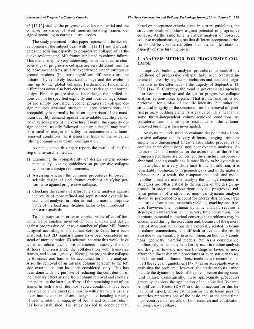
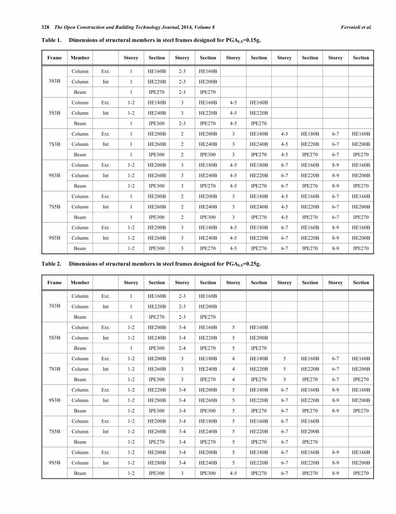
Table 1. Dimensions of structural members in steel frames designed for PGALS=0.15g.
Fig. (3). Displacement Controlled (DC-PD) and Staged Construction (SC-PD) Pushdown curves. Design PGA=0.15g.
dropped, the load factor versus vertical displacement rela-tionships resulted from both methods are identical, and so they are represented by a single dashed line. The end point of the DC-PD curves is defined by the attainment of the accep-tance criterion suggested by GSA Guidelines.
The results clearly show that MRF steel frames designed according to current provisions given in seismic codes are not able to resist progressive collapse after column removal. According to the pushdown analysis results, the failure con-dition for vertical deflection given in the GSA Guidelines is
330 The Open Construction and Building Technology Journal, 2014, Volume 8 Ferraioli et al.
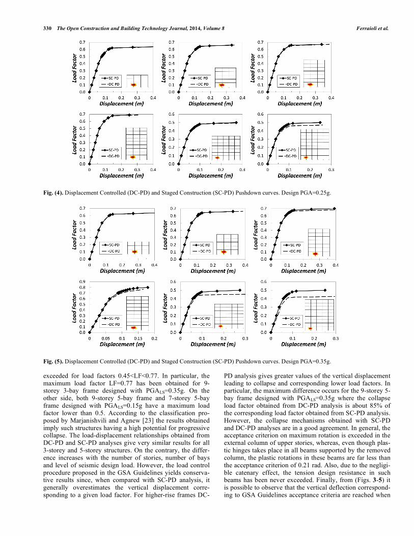
Fig. (4). Displacement Controlled (DC-PD) and Staged Construction (SC-PD) Pushdown curves. Design PGA=0.25g.
Fig. (5). Displacement Controlled (DC-PD) and Staged Construction (SC-PD) Pushdown curves. Design PGA=0.35g.
exceeded for load factors 0.45<LF<0.77. In particular, the maximum load factor LF=0.77 has been obtained for 9-storey 3-bay frame designed with PGALS=0.35g. On the other side, both 9-storey 5-bay frame and 7-storey 5-bay frame designed with PGALS=0.15g have a maximum load factor lower than 0.5. According to the classification pro-posed by Marjanishvili and Agnew [23] the results obtained imply such structures having a high potential for progressive collapse. The load-displacement relationships obtained from DC-PD and SC-PD analyses give very similar results for all 3-storey and 5-storey structures. On the contrary, the differ-ence increases with the number of stories, number of bays and level of seismic design load. However, the load control procedure proposed in the GSA Guidelines yields conserva-tive results since, when compared with SC-PD analysis, it generally overestimates the vertical displacement corre-sponding to a given load factor. For higher-rise frames DC-
PD analysis gives greater values of the vertical displacement leading to collapse and corresponding lower load factors. In particular, the maximum difference occurs for the 9-storey 5-bay frame designed with PGALS=0.35g where the collapse load factor obtained from DC-PD analysis is about 85% of the corresponding load factor obtained from SC-PD analysis. However, the collapse mechanisms obtained with SC-PD and DC-PD analyses are in a good agreement. In general, the acceptance criterion on maximum rotation is exceeded in the external column of upper stories, whereas, even though plas-tic hinges takes place in all beams supported by the removed column, the plastic rotations in these beams are far less than the acceptance criterion of 0.21 rad. Also, due to the negligi-ble catenary effect, the tension design resistance in such beams has been never exceeded. Finally, from (Figs. 3-5) it is possible to observe that the vertical deflection correspond-ing to GSA Guidelines acceptance criteria are reached when
Assessment of Progressive Collapse Capacity The Open Construction and Building Technology Journal, 2014, Volume 8 331
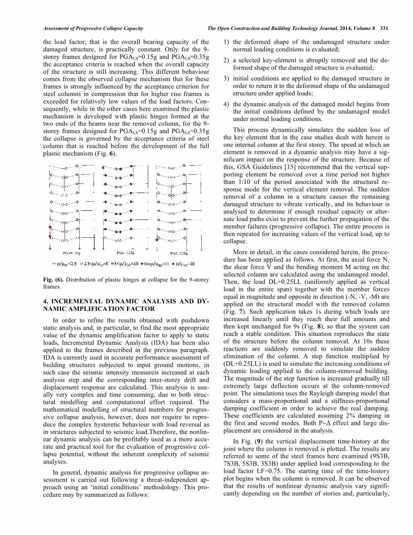
the load factor, that is the overall bearing capacity of the damaged structure, is practically constant. Only for the 9-storey frames designed for PGALS=0.15g and PGALS=0.35g the acceptance criteria is reached when the overall capacity of the structure is still increasing. This different behaviour comes from the observed collapse mechanism that for these frames is strongly influenced by the acceptance criterion for steel columns in compression that for higher rise frames is exceeded for relatively low values of the load factors. Con-sequently, while in the other cases here examined the plastic mechanism is developed with plastic hinges formed at the two ends of the beams near the removed column, for the 9-storey frames designed for PGALS=0.15g and PGALS=0.35g the collapse is governed by the acceptance criteria of steel column that is reached before the development of the full plastic mechanism (Fig. 6).
Fig. (6). Distribution of plastic hinges at collapse for the 9-storey
frames.
4. INCREMENTAL DYNAMIC ANALYSIS AND DY-
NAMIC AMPLIFICATION FACTOR
In order to refine the results obtained with pushdown static analysis and, in particular, to find the most appropriate value of the dynamic amplification factor to apply to static loads, Incremental Dynamic Analysis (IDA) has been also applied to the frames described in the previous paragraph. IDA is currently used in accurate performance assessment of building structures subjected to input ground motions, in such case the seismic intensity measureis increased at each analysis step and the corresponding inter-storey drift and displacement response are calculated. This analysis is usu-ally very complex and time consuming, due to both struc-tural modelling and computational effort required. The mathematical modelling of structural members for progres-sive collapse analysis, however, does not require to repro-duce the complex hysteretic behaviour with load reversal as in structures subjected to seismic load.Therefore, the nonlin-ear dynamic analysis can be profitably used as a more accu-rate and practical tool for the evaluation of progressive col-lapse potential, without the inherent complexity of seismic analyses.
In general, dynamic analysis for progressive collapse as-sessment is carried out following a threat-independent ap-proach using an ‘initial conditions’ methodology. This pro-cedure may by summarized as follows:
1) the deformed shape of the undamaged structure under normal loading conditions is evaluated;
2) a selected key-element is abruptly removed and the de-formed shape of the damaged structure is evaluated;
3) initial conditions are applied to the damaged structure in order to return it to the deformed shape of the undamaged structure under applied loads;
4) the dynamic analysis of the damaged model begins from the initial conditions defined by the undamaged model under normal loading conditions.
This process dynamically simulates the sudden loss of the key element that in the case studies dealt with herein is one internal column at the first storey. The speed at which an element is removed in a dynamic analysis may have a sig-nificant impact on the response of the structure. Because of this, GSA Guidelines [15] recommend that the vertical sup-porting element be removed over a time period not higher than 1/10 of the period associated with the structural re-sponse mode for the vertical element removal. The sudden removal of a column in a structure causes the remaining damaged structure to vibrate vertically, and its behaviour is analysed to determine if enough residual capacity or alter-nate load paths exist to prevent the further propagation of the member failures (progressive collapse). The entire process is then repeated for increasing values of the vertical load, up to collapse.
More in detail, in the cases considered herein, the proce-dure has been applied as follows. At first, the axial force N, the shear force V and the bending moment M acting on the selected column are calculated using the undamaged model. Then, the load DL+0.25LL (uniformly applied as vertical load in the entire span) together with the member forces equal in magnitude and opposite in direction (-N, -V, -M) are applied on the structural model with the removed column (Fig. 7). Such application takes 1s during which loads are increased linearly until they reach their full amounts and then kept unchanged for 9s (Fig. 8), so that the system can reach a stable condition. This situation reproduces the state of the structure before the column removal. At 10s these reactions are suddenly removed to simulate the sudden elimination of the column. A step function multiplied by (DL+0.25LL) is used to simulate the increasing conditions of dynamic loading applied to the column-removed building. The magnitude of the step function is increased gradually till extremely large deflection occurs at the column-removed point. The simulations uses the Rayleigh damping model that considers a mass-proportional and a stiffness-proportional damping coefficient in order to achieve the real damping. These coefficients are calculated assuming 2% damping in the first and second modes. Both P effect and large dis-placement are considered in the analysis.
In Fig. (9) the vertical displacement time-history at the joint where the column is removed is plotted. The results are referred to some of the steel frames here examined (9S3B, 7S3B, 5S3B, 3S3B) under applied load corresponding to the load factor LF=0.75. The starting time of the time-history plot begins when the column is removed. It can be observed that the results of nonlinear dynamic analysis vary signifi-cantly depending on the number of stories and, particularly,
332 The Open Construction and Building Technology Journal, 2014, Volume 8 Ferraioli et al.
Fig. (7). Applied load for dynamic analysis.
Fig. (8). Time-history function of applied load for dynamic analysis.
Fig. (9). Vertical displacement time-history at the joint where the column is removed
the maximum vertical displacement decreases when the number of stories increases.
In Figs. (10-12) the peak displacement response of each time-history is plotted against the load factor LF to create the load-displacement envelopes for the incremental dynamic analysis. The IDA plots are then compared with the push-down curves obtained with DC-PD analyses when a dynamic amplification factor DAF in the range [1.0-2.0] is applied. It can be observed that when a DAF of 2 is considered, both stiffness and strength of the load-displacement curves ob-tained from IDA are higher than those from the pushdown analyses in all structures. Therefore, the load-resisting capac-ity represented by the load factor tends to be underestimated when it is predicted by pushdown analyses. This confirms that, assuming a DAF equal to 2, the nonlinear static analysis approach leads to an over conservative estimation of pro-gressive collapse resistance for a column-removed building. In this study, the appropriate value of the dynamic amplifica-tion factor (DAF) to be applied in pushdown analysis for a more accurate estimation of the collapse resistance has been evaluated. To this aim, the root-mean-square error (RMSE) has been used as a measure of the differences between the values predicted by pushdown static analysis and the values obtained by incremental dynamic analysis. In particular, the RMSE has been calculated using the values of the load fac-tors from IDA and pushdown analysis corresponding to the same vertical displacement. In Fig. (13) the RMSE is plotted as a function of the dynamic amplification factor (DAF) for the frames designed with: a) PGASLV=0.15 g; b) PGASLV=0.25 g; c) PGASLV=0.35g. The results show that
the minimum error occurs when DAF=1.3 in 3-bay frames, while in 5-bay frames the minimum occurs for values of DAF lower than 1.3. In Fig. (13d) the averaged RMSE for all the structures examined is plotted, showing that a value in the range of 1.25÷1.3 seems to better represent the dynamic effect for all the examined steel moment resisting frames. Even though this result confirms the great conservativeness of the nonlinear static analysis method when a DAF=2 is assumed, however it should be noted that the RMSE between pushdown analysis and IDA is calculated by considering the load factors for the same vertical displacement. This implies that the failure load factor for pushdown analysis and IDA is calculated using the same acceptance criteria whereas, in general, different acceptance criteria should be used for non-linear static and dynamic methods. This would suggest to assume, in a prudential way, a slightly higher DAF value, for instance in the order of 1.5.
CONCLUSION
This paper has investigated the response to progressive collapse of steel moment resisting frames designed accord-ing to the Italian Seismic Code. The main purpose of the study has been to verify whether the current provisions adopted for seismic design enable a satisfying performance in case one of the supporting column is suddenly removed from the structure, that is the case in which the progressive collapse potential is involved. Both static nonlinear and in-cremental dynamic approaches have been followed in order to estimate the load bearing capacity of the structure. Ac-cording to the static pushdown analysis results, the failure
Assessment of Progressive Collapse Capacity The Open Construction and Building Technology Journal, 2014, Volume 8 333
Fig. (10). Pushdown curves and load-displacement envelopes from incremental dynamic analysis. Design PGA=0.15g.
Fig. (11). Pushdown curves and load-displacement envelopes from incremental dynamic analysis. Design PGA=0.25g.
334 The Open Construction and Building Technology Journal, 2014, Volume 8 Ferraioli et al.
Fig. (12). Pushdown curves and load-displacement envelopes from incremental dynamic analysis. Design PGA=0.35g.
Fig. (13). Root-mean-square error (RMSE) of pushdown analysis as a function of dynamic increase factor (DAF): a) Design PGA=0.15g;
b) Design PGA=0.25g; c) Design PGA=0.35g. d) Average value of RMSE for all structures.
criterion for vertical deflection given in the GSA Guidelines
was exceeded for load factors in the range 0.45<LF<0.77.
This means that the investigated earthquake-resistant steel
MR frames have a high potential for progressive collapse,
especially for 5 bays higher-rise frames designed with
PGALS=0.15g, for which the load factor is lower than 0.5. In
these cases not only the load resisting capacity, but also the
displacement capacity may be significantly smaller. This
results from the maximum acceptable ductility for steel col-
umns in compression, that for higher rise frames may be
Assessment of Progressive Collapse Capacity The Open Construction and Building Technology Journal, 2014, Volume 8 335
exceeded for relatively low values of the load factors and
vertical displacements. In these cases, when the collapse
arises due to the plastic hinge in one column, the plastic rota-
tions in beams are relatively small when compared with
those obtained for lower-rise frames and far less than the
acceptance criterion of 0.21 rad. The two procedures used for
pushdown analysis give very similar results for lower-rise
frames, where as the difference increases with number of
stories, number of bays and level of seismic design load. In
particular, the load control procedure proposed in GSA
Guidelines generally underestimates the load factor and the
greatest difference (about 15%) occurs for the 9-storey 5-bay
frame designed with PGALS=0.35g. However, it should be
noted that this load control procedure that applies gravity
loads to the damaged structure generally gives conservative
estimates. In fact, it provides lower load factors leading to
collapse if compared with the procedure that applies gravity
loads to the undamaged structure and then removes the col-
umn. Besides, frame action is the sole source of progressive
collapse resistance because inelastic deformations corre-
sponding to the GSA acceptance criteria are not large enough
to activate catenary actions in beams.
Table 4. Acceptance criteria for progressive collapse (GSA
2003).
Component Ductility Rotation (rad)
Steel beams 20 0.21
Steel Columns (tension controls) 20 0.21
Steel Columns
(compression controls) 1 -
According to incremental dynamic analysis, the 3-bay
steel MRF frames have exhibited adequate resistance to pro-gressive collapse since acceptance criteria have been not exceeded for load factor LF 1. On the contrary, the 5-bay frames exceed the failure criterion for load factor LF<1. This means that these earthquake-resistant steel MR frames ex-hibit a potential for progressive collapse even when the more progressive dynamic analysis is applied. Eventually, the dy-namic amplification factor to be applied in pushdown analy-sis for the accurate estimation of the collapse resistance has been evaluated. At this aim, the root-mean-square error was used to measure the difference between pushdown analysis and incremental dynamic analysis. The results have showed that a factor in the order of 1.25÷1.30 better represents the dynamic effect for the earthquake-resistant steel frames con-sidered here.
CONFLICT OF INTEREST
The authors confirm that this article content has no con-flict of interest.
ACKNOWLEDGEMENTS
The subject dealt with in this paper is a part of the re-search project RELUIS 2014-2018 “Steel and composite
steel-concrete structures” (Coordinators Prof. R. Zandonini, Prof. R. Landolfo), issued by the Italian “Dipartimento della Protezione Civile”. The activity described in the paper was carried out by the members of Research Unit of the Second University of Naples, coordinated by Prof. A. Mandara.
REFERENCES
[1] P. Ruth, K.A. Marchand and E.B. Williamson, “Static equivalency
in progressive collapse alternative path analysis reducing conserva-
tism while retaining structural integrity”, Journal of Performance
of Construction Facilities, ASCE, vol. 20, no. 4, pp. 349-364,
2006.
[2] B.A. Izzuddin, A.G. Vlassis, A.Y. Elghazouli and D.A. Nethercot,
“Progressive collapse of multi-storey buildings due to sudden col-
umn loss - part I: simplified assessment framework”, Engineering
Structures, Elsevier, vol. 30, no. 5, pp. 1308-1318, 2008.
[3] F. Fu, “3-D nonlinear dynamic progressive collapse analysis of