161
Agence nationale pour la gestion des déchets radioactifs SYNTHESIS Assets of granite formations for deep geological disposal Report Series June 2005
| Date post: | 03-Jan-2017 |
| Category: |
Documents |
| Upload: | nguyentruc |
| View: | 218 times |
| Download: | 0 times |

Agence nationale pour la gestion des déchets radioactifs
SYNTHESIS
Assets of granite formations for deep geologicaldisposal
Rep
ort S
erie
s
Do
ssie
r 2
00
5
GRAN
ITE
: SYN
TH
ESIS
- Assets
of gra
nite
form
ations for
deep g
eolo
gical disposal
June 2005
©A
ndra
- 2
67 V
A -
Decem
ber
2006 -
Gra
phic
desig
n:
Media
géra
nce -
IS
SN
: 1
772-2
136
Agence nationale pour la gestion des déchets radioactifs
Parc de la Croix Blanche - 1/7, rue Jean Monnet - F 92298 Châtenay-Malabry Cedex Tél. : 01 46 11 80 00
www.andra.fr
The Andra Publication SeriesEssential SeriesIn a few pages, documents in the Essential Series provide simple and illustrated explanations with a view to furtheringknowledge on radioactive waste and Andra.
Reference SeriesWith standard information concerning Andra methods and progress reports on its investigations or activities, theReference Series presents various technical and other information, especially on the location of radioactive waste.
Periodical SeriesOn a regular basis, Andra publishes various brochures relating to the environmental monitoring of its disposal and research facilities. The Periodical Series includes those publications as well as the respective news bulletins of each site.
Discovery SeriesVideos, CD-ROMs, synthesis images and comic strips… are worth more than a thousand words. The Discovery Seriesuses vivid illustrations to explain to a broad public the underlying principles of radioactive-waste management.
Science and Technology SeriesTaking stock of current knowledge, presenting ongoing research as well as the Agency's methods and approachesconstitute the objectives of the Science and Technology Series. Intented for a specialised public, it provides varioussyntheses and monographs published under the aegis of Andra or in partnership with other scientific organisations.
Report SeriesSummaries, reports and seminar proceedings published in the Report Series highlight the advances of Andra's
ongoing investigations.
Industrial Practices SeriesThe Industrial Practices Series includes documents dealing with the acceptance criteria and the management ofradioactive waste.
95467_COUV Synthèse_Granite 6/04/07 18:23 Page 1

The present English version is a translation of the original “Dossier2005 Granite“ documentation written in French, which remains ultima-tely the reference documentation.
In order to be consistent through the various documents, while theword ''storage'' (''entreposage'' in French) refers only to temporarymanagement (in terms of concept and facility), ''disposal'' (in term ofconcept) and ''repository'' (in terms of facility or installation) refers tolong term management of high level long lived radioactive waste(''stockage'' in French for these words).
95467_Sommaire_Granite 11/04/07 10:18 Page 2

Introductionp.04 > Assets of granite formations for deep geological disposal
Chapter 1p.11 > Packages
Chapter 2p.29 > Design study for a repository in granite medium
Chapter 3p.51 > Understanding and modelling granite
Chapter 4p.83 > Description of repository design in a granite medium
Chapter 5p.113 > Long-term safety
p.150 >Conclusion
Contents
95467_Sommaire_Granite 11/04/07 10:18 Page 3

4
ANDRA > Assets of granite formations for deep geological disposal. Dossier 2005 Granite
IntroductionI. Assessment of the feasibility of
a geological high-level, long-lived waste (HLLL) repository:the Andra researchframework
I.1 The Law of 30 December 1991By the Law of 30 December 1991 on the management of high-level, long-lived waste (HLLL), referred to inarticle L542 of the Environment Code, the National Radioactive Waste Management Agency (Andra) wasconferred the mission of assessing the feasibility of deep geological disposal of high level long lived radioactivewaste (HLLL, HAVL in French) and, in particular, through the construction and operation of underground labora-tories (2nd avenue of the Law). Later the government requested Andra to carry out its work with a rationale ofreversibility. On the other hand, the Atomic Energy Commission (CEA) is the steering body in charge ofresearch on the partitionning and transmutation of the HLLL waste (1st avenue of the Law), as well as theirstorage and conditioning (3rd avenue).
Within this framework, the research was conducted, with tools and at different levels of maturity, on two typesof geological media: clay and granite. The present report is a synthesis of work performed by Andra for thestudy of a geological repository in a granite formation. Another report presents the detailed knowledgeacquired in the field of clay media.
The Law of December 1991 institutes a National Review Board (CNE), an independent commission of Frenchand foreign scientific experts, in order to carry out a continuous assessment of the research conducted by theCEA and Andra and publish a yearly evaluation report. The Law stipulates that the government will address tothe Parliament a global research assessment report, prepared by the CNE, as input to the 2006 parliamentarydebate.
Since 1996, the Ministry of Research has been coordinating the elaboration, implementation and follow-up ofthe strategy and the research programmes carried out by Andra and the CEA. The Nuclear Safety Authority andits technical support, the Institution of Radioprotection and Nuclear Safety (IRSN), have also examined theresearch results from a safety viewpoint.
The Law of 1991 states the main principles to be taken into account in the research initiative and, in particular,the necessity of working “by respecting the protection of the nature, environment and health” and “takinginto consideration the right of future generations”. In particular, a problem should not be bequeathed to themwithout a solution, while they should be allowed to retain control over the committed process.
95467_Intro_GRANITE.qxd 11/04/07 12:46 Page 4
I.2 The Basic Safety Rule (RFS III.2.f.)The Nuclear Safety Authority issued in 1991 a basic safety rule (RSF III.2.f), which provides a framework forlong-term safety expectations with respect to disposal design principles, favourable geological media choicecriteria and study modalities.
It presents the basic objectives which must serve as guidelines for the work on geological disposal :protection of man and the environment against possible consequences of radioactive waste, limitation of theradiological impact of a repository to a level as low as reasonably achievable, and it specifies the necessity ofa multi-barrier disposal concept, namely the packages containing the waste, the engineered barrier(components and materials between the package and the geological medium), the geological medium itself.
The RFS indicates the major expectations with respect to a potential site : long-term geodynamic stability (inparticular, no significant earthquake risk), no important water circulation in the geological medium, adequatemechanical properties of the rocks to allow excavating underground installations, confinement properties of thegeological medium with respect to the radionuclides, a sufficient depth to protect the waste from variousaggressions, no exploitable outstanding natural resources in the vicinity.
II. The Andra research programme into a repositoryin a granite formation
II.1 A generic approach towards a geological studyTogether with clay, granite is one of the geological formations studied by Andra in the context of the Law of 30December 1991.
Since no site was available, studies on the granite medium were not meant to assess the feasibility of arepository designed to satisfy the specific aspects of a particular location. The objective of the researchprogramme has been to assess the interest of the granite medium for a repository. Thus, Andra has identifiedand dealt with the major issues concerned by a repository in a granite medium, in order to check that granitemedium is not ruled out by any of them and to examine possible technical options.
The approach has been to study generic architectural designs for a repository, based on the properties of thegranite medium. The proposed options have formed the basis for analyses to understand the long-term of arepository and to assess its safety.
Andra has the following mission :
- act as a global programme agency, which orients the research and animates the scientific and technicalcommunity interacting in this field ;
- assess the feasibility of a possible deep geological repository with a rationale of reversibility, notablythrough research conducted in underground laboratory. As far as the granite medium is concerned, sofar no underground laboratory is available in France, but Andra is benefiting from knowledge acquired inforeign laboratories (Aspö in Sweden, Grimsel in Switzerland) and is pursuing its work in order to assessFrench granite potentialities. For the clay medium, the Meuse/Haute-Marne underground laboratorycreated by the Decree of August 1999 is available to Andra as well as foreign underground laboratories.
IntroductionANDRA > Assets of granite formations for deep geological disposal. Dossier 2005 Granite
5
95467_Intro_GRANITE.qxd 11/04/07 12:46 Page 5

6
ANDRA > Assets of granite formations for deep geological disposal. Dossier 2005 Granite
This rationale forms the basis for the research programme focusing on four complementary areas for study:
- Study of the granite mediumA generic repository design depends on the properties of the granite. The research has included overall studiesto understand and model the granite medium and an analysis of the variability in the characteristics of Frenchgranites, to adapt the design studies and carry out the safety assessments and analyses.
- The generic design of a repository in a granite mediumFrom design principles based on safety, the studies have proposed waste conditioning, generic repositoryarchitectures, operating methods and closure of the repository allowing for reversibility.
- Repository behaviour and its long-term evolutionBased on the proposed options, the studies have analyzed the long-term repository behaviour, to understandand model the thermal, mechanical, chemical and hydraulic phenomena involved in a repository in a granitemedium.
- Long-term safety analysesThe safety analyses performed in the context of generic studies have not attempted to assess repositoryperformance on one or several specific granite sites: they have identified the major parameters for theperformance of a repository in a granite medium compared with the objectives of protecting man and hisenvironment and appraised the robustness of the design options proposed.
Granite studies: milestones since 1991
Within the framework of the 1991 Law, Andra carried out surveys between 1994 and 1996 with a viewto site an underground laboratory in the south of the Vienne district. The granite massif chosen wasgranite overlaid by sedimentary formations, delimited from geophysical and geological data.
In 1997 the National Review Board (CNE) reported unfavourably on the Vienne site, particularly on therisks of fluids circulating between the granite and the aquifers exploited in the sedimentary overlyingformations; it underlined the interest of "outcropping" granites that would have more favourablecharacteristics.
The Government decided officially not to retain the Vienne site on 9 December 1998 and planned for theresearch into other potential sites for a research laboratory in a granite medium. A consultation missionwas organised in 1999 to present this project and assess public opinion on fifteen sites selected on thebasis of geological criteria. These fifteen sites, submitted to a committee of national and internationalexperts, were identified from previous selection approaches and advances in knowledge of the granitemedium in France and abroad. The mission report in July 2000 highlighted the consultation processfailure.
According to government expectations, Andra has designed in 2000 a research programme taking stockof current knowledge acquired in foreign underground research laboratories and in various geologicalenvironments.
The contextual differences for the studies between the clay and granite formations lead Andra to organiseits research into two distinct projects: one to study a repository in a clay medium, based on theMeuse/Haute-Marne underground laboratory, and the second to study a repository in a granite medium.
Some studies were common to both projects, especially those involving waste packages and materials,but the results were applied specifically to each project.
In this context, the Dossier 2002 Granite put forward in 2002 a first assessment of the studies andresearch into a potential repository in a granite medium.
This report draws conclusions from numerous studies conducted since 1991. On this basis, it attemptsto assess the interest of a granite medium for a high-level, long-lived waste repository.
95467_Intro_GRANITE.qxd 11/04/07 12:46 Page 6

IntroductionANDRA > Assets of granite formations for deep geological disposal. Dossier 2005 Granite
7
II.2 Support from international cooperation andmobilisation of the national scientific community
Andra has relied extensively on foreign studies and has played an active part in experimental programmes inthe Swedish, Swiss and Canadian underground laboratories.
The main cooperation themes have involved the study of the granite medium: structuring and fracturing of agranite massif, survey methods, underground water flows, retention capabilities of radionuclides in the rockand so on.
Examples of joint experimentation programmes with foreign partners
The repository design studies have also been based on demonstration elements acquired in undergroundlaboratories and concerning the installation and behaviour of engineered repository components as seals,backfill, engineered barrier, etc.
Lastly, the study approach has benefited from feedback acquired abroad for the safety analysis of a repositoryin a granite medium, particularly in Sweden and Finland.
This approach has therefore made the most of the extensive knowledge acquired internationally on the studiesinto a repository in a granite medium.
Andra has also established national scientific partnerships (CEA “French Atomic Energy Commission”, BRGM“National Geological Survey”, the Forpro Research Group with the CNRS “French National Centre for ScientificResearch” and the Ecole des Mines “School of Mines” in Paris). Apart from French research teams partici-pating in foreign programmes, this has dealt with the issue of not transposing results obtained abroad to theFrench geological context without examining the scientific and technical relevance of such an approach.
II.2.1 The scope of the approachWithout any specific study site, the approach adopted, based especially on numerous data acquiredinternationally, has allowed Andra to ascertain the various aspects to be considered when designing andassessing a repository. It has led to proposals for "generic" repository designs, with the potential to ensure, inthe French geological context, the suitability of a repository faced with long-term safety objectives.
95467_Intro_GRANITE.qxd 11/04/07 12:46 Page 7

8
ANDRA > Assets of granite formations for deep geological disposal. Dossier 2005 Granite
This approach does not however claim to draw the same conclusions as an approach reinforced by surfacesurveys on a granite site followed by work in an underground laboratory. Only, such a complete programmecould provide sufficient knowledge of the properties of a granite from which may be drawn a fair assessmentof repository feasibility.
The specific characteristics of a site would require adjusting the design of the repository components to theproperties of the granite studied, adapting its architecture to the massif structure, specifying how it isconstructed and operated and assessing accurately the options retained with regards to long-term safety objectives.
II.2.2 Structure of the Dossier 2005 The Dossier 2005 includes firstly, the presentation, in the form of "reference documents", of the knowledgeunderlying the design of a repository and its analysis and, secondly, a three "volume" summary of the designoptions proposed and the related scientific and safety analyses.
• "Knowledge reference documents"
Andra has structured the acquisition of knowledge around reference documents. Three are shared with the"clay" dossier:
- repository materials reference document, grouping data relating to the behaviour of materials (steels,concretes, etc.) other than the rock formation hosting the repository.
- reference document on the behaviour of the high-level, long-lived waste packages, which summarizes theknowledge and models on waste behaviour in a repository environment,
- reference document concerning the waste inventory dimensioning model, which list all the high-level, long-lived waste produced and yet to be produced by existing nuclear facilities.
A fourth set of reference document specific to the granite medium assembles the data available on the Frenchgranites as a typological analysis.
• Three "volumes"
Three volumes summarize the knowledge acquired from the point of view of each of the areas in the studyprogramme:
- one volume on "Architecture and management of a geological repository"Andra suggests generic options for repository architectures that are both feasible with respect toexpectations, particularly safety and reversibility, and realistic from an industrial viewpoint. Based on availableknowledge and technology, the technical options studied, chosen to be as simple and robust as possible,show that solutions do exist for a repository in a granite medium.
The options have formed the basis for analyzing repository safety, particularly its behaviour and evolution overvarious timescales. This analysis is the subject of the two other volumes in the dossier.
- one volume on "Phenomenological evolution of a geological repository"The design and safety assessment of a repository is based on understanding its phenomenological evolutionand that of its environment, to take account ultimately of the processes conditioning or controlling thebehaviour and migration of radionuclides in the environment at the scale of a million years.
This volume presents the body of knowledge acquired on the granite medium and on repositoryphenomenology.
- one volume on "Safety analysis of a geological repository"This volume describes the safety analysis approach to a repository in a granite medium in a generic studycontext.
95467_Intro_GRANITE.qxd 11/04/07 12:46 Page 8

IntroductionANDRA > Assets of granite formations for deep geological disposal. Dossier 2005 Granite
9
95467_Intro_GRANITE.qxd 11/04/07 12:46 Page 9

10
ANDRA > Assets of granite formations for deep geological disposal. Dossier 2005 Granite
95467_Chap1_GRANITE.qxd 11/04/07 12:48 Page 10

11
1Packagesp.12 > 1. High-level and long-lived waste
p.16 > 2. The inventory model
p.24 > 3. The long-term behaviour of the waste packages
ANDRA > Assets of granite formations for deep geological disposal. Dossier 2005 Granite
95467_Chap1_GRANITE.qxd 11/04/07 12:48 Page 11
PackagesThe feasibility study of a high-level long-lived waste repository, its design and safety assessment relies on theknowledge of packages:
- quantity, types and characteristics of current and future packages,
- long-term phenomenological behaviour in a repository situation, particularly the possible release of radionuclides.
1. High-level and long-lived waste
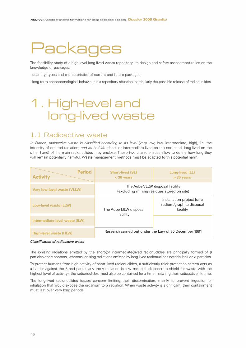
1.1 Radioactive wasteIn France, radioactive waste is classified according to its level (very low, low, intermediate, high), i.e. theintensity of emitted radiation, and its half-life (short- or intermediate-lived on the one hand, long-lived on theother hand) of the main radionuclides they enclose. These two characteristics allow to define how long theywill remain potentially harmful. Waste management methods must be adapted to this potential harm.
Classification of radioactive waste
The ionising radiations emitted by the short-(or intermediate-)lived radionuclides are principally formed of βparticles and γ photons, whereas ionising radiations emitted by long-lived radionuclides notably include α particles.
To protect humans from high activity of short-lived radionuclides, a sufficiently thick protection screen acts asa barrier against the β and particularly the γ radiation (a few metre thick concrete shield for waste with thehighest level of activity); the radionuclides must also be contained for a time matching their radioactive lifetime.
The long-lived radionuclides issues concern limiting their dissemination, mainly to prevent ingestion orinhalation that would expose the organism to α radiation. When waste activity is significant, their containmentmust last over very long periods.
Period Short-lived (SL) Long-lived (LL)
Activity < 30 years > 30 years
Very low-level waste (VLLW)
Low-level waste (LLW)
Intermediate-level waste (ILW)
High-level waste (HLW)
The Aube VLLW disposal facility(excluding mining residues stored on site)
Installation project for a radium/graphite disposal
The Aube LILW disposal facilityfacility
Research carried out under the Law of 30 December 1991
ANDRA > Assets of granite formations for deep geological disposal. Dossier 2005 Granite
12
95467_Chap1_GRANITE.qxd 11/04/07 12:48 Page 12

1
PackagesANDRA > Assets of granite formations for deep geological disposal. Dossier 2005 Granite
1.2 High-level and long-lived waste
1.2.1 Type and sourceHigh-level and long-lived waste accounts for about 5% of the volume of radioactive waste produced in France.It contains large quantities of short- or intermediate-lived radionuclides (producing a high activity level) andmoderate to very large quantities of long-lived radionuclides.
C waste storage facility
Radioactive decay and half-life – radiation type
A radioactive isotope of an element is physically unstable due to an excess of protons or neutrons in itsnucleus. The nucleus may be transformed spontaneously into another stable or still radioactive nucleus:this irreversible transformation, or disintegration, is accompanied by the emission of an alpha (heliumnucleus made up of two protons and two neutrons) or beta (electron or positron) particle and a gammaphoton. Radioactive disintegration of a given nucleus is a random phenomenon over time. It is howeverpossible to define a period (or half-life) for each radioactive isotope, which is the time taken by 50% ofthe initial quantity to disintegrate. Thus, the radioactive half-life of carbon isotope 14 (14C) is 5,730 years.As disintegration occurs, a progressively lesser quantity of the radioactive isotope remains. This gradualreduction in radioactivity is called radioactive decay. After a period of n half-lives of a radioactive isotope,this will decrease by 1/2n compared with the initial inventory; thus, after ten half-lives, only a thousandthof the initial radioactive material will remain approximately.
Three types of radiation
- Alpha (α): emission of particles made up of helium atom nuclei with little penetration (diffusion in theair only on a few centimetres). These particles can be stopped by a sheet of paper.
- Bêta (β): electrons that penetrate several metres in air. A sheet of aluminium or a pane of glass can stop them.
- Gamma (γ): electromagnetic radiation with far greater penetration, similar to X-rays. Several centimetres oflead or several tens of centimetres of concrete are needed to stop them.
13
95467_Chap1_GRANITE.qxd 11/04/07 12:48 Page 13

The main sectors of activity contributing to the production of this waste are the electro-nuclear industry (EDFnuclear power plant reactors, Cogema fuel reprocessing plants at La Hague and Marcoule) and research andnational defence activities (CEA centres). Apart from spent fuel reprocessing residues, must be taken inaccount waste produced by operation and maintenance in reprocessing and nuclear power plants.
Spent fuel unloaded from the EDF reactors are reprocessed in Cogema plant at La Hague. The aim of repro-cessing is to separate the uranium and plutonium, themselves not considered as waste, from the waste itself:fission products, activation products, minor actinides conditioned in La Hague plant [1]. Added to these high-level residues are essentially metallic materials from fuel assemblies and intermediate-level operating andmaintenance waste from reprocessing plant (liquid effluents, etc.). The recovered uranium and plutonium areused in manufacturing MOX (mixed uranium - plutonium oxide) and URE (reprocessed uranium) fuels. After usein the reactors, they are stored temporarily while awaiting reprocessing according to EDF industrial strategy formanaging the fuel cycle backend.
Nuclear reactor operations also generate intermediate-level waste: this involves devices for starting up andoperating the reactors which, after some time in service, are replaced and therefore become waste. This wasteis currently stored on the nuclear power plant sites.
The long-lived waste produced by sectors other than electro-nuclear production (research, defence) is usuallyintermediate-level technological waste: replaced or obsolete parts, contaminated by processed materials andradioactive waste, etc. Note also the existence of a small quantity of spent fuel produced by research ordefence reactors, for which disposal possibilities are being studied.
1.2.2 Two categories of waste
1.2.2.1 High-level waste (or vitrified waste), also known as C waste
It accounts for 1% of the volume of radioactive waste and relates tounrecoverable material contained in solutions from spent fuel reprocessing inthe Cogema plants: fission products, minor actinides, activation products. Its high β-γ level generates considerable heat which decreases over time,principally with the radioactive decay of the fission products with average half-lives (caesium137, strontium90).
Nowadays, it is incorporated in a borosilicate glass matrix (R7T7 glass), with aparticularly high and long-lasting containment capacity (several hundreds ofthousands of years) under favourable physico-chemical environment conditions.The radionuclides are thus spread uniformly in the glass matrix. This vitrifiedwaste is poured into stainless steel drums, to make up vitrified C waste primarypackages.
Standard container for vitrified waste (CSD-V)
[1] The UP2-400 La Hague and UP1 Marcoule plants, now decommissioned, processed fuels from the graphite-gas and fast neutronreactors. Fission product solutions were conditioned by vitrification; on the other hand, effluent sludges were embedded in bitumen atMarcoule plant.
14
ANDRA > Assets of granite formations for deep geological disposal. Dossier 2005 Granite
95467_Chap1_GRANITE.qxd 11/04/07 12:48 Page 14

1
1.2.2.2 Intermediate-level, long-lived waste, also known as B waste
This comes mainly from nuclear fuel manufacturing and processing plants, and research centres. It thereforeincludes a large variety of items such as structural elements from fuel assemblies (cladding from the fuel rodscalled "hulls", end pieces called "end caps" and assembly spacer grids, etc.), sludge from effluent treatment,miscellaneous equipment (filters, pumps, etc.). This is basically metal but organic and inorganic componentssuch as plastics and cellulose may also be included.
Its β-γ level is low or intermediate and ittherefore generates little or no heat.However, the quantity of long-livedelements that it contains justifies a verylong-term containment, like that for Cwaste.
Depending on type, it is conditioned inbitumen (sludge from effluent treatment),in concrete or by compacting (hulls andend pieces, technological waste). Theconditioned waste is then placed inconcrete or steel drums. These drumsmake up the B waste primary packageswhich are both more numerous and morediverse through their conditioning.
Standard container Concrete fiber-reinforced container
for compacted waste (CSD-C) (technological waste)
There are three types of radionuclides produced in a reactor:
- fission products are produced directly from the fission of the uranium and plutonium atoms: caesium,strontium, iodine, technetium, etc. or through fission fragment disintegration. Caesium137 (and itsdaughter product barium137) and strontium90 (and its daughter product yttrium90) cause most of theradiation and heat release of the HLLL waste, that are very high during the first 300 years given theirhalf-life of thirty years.
- actinides are natural or artificial elements with a nucleus counting a proton quantity higher than or equalto 89. Four actinides exist in the natural state: actinium, thorium, protactinium and uranium. Minoractinides (mainly americium, curium and neptunium) are formed in a reactor by successive neutroncaptures from fuel nuclei. Their radioactivity and heat rating decrease slowly. After decay of the fissionproducts with average half-lives, the waste generates residual heat from the activity of americium241,which in turn decreases gradually.
- activation products are formed by the capture of neutrons mainly in fuel cladding and structurematerials. They have considerably less radioactivity than fission products and minor actinides, but mustbe taken into account as some of these radionuclides have a long radioactive half-life.
15
PackagesANDRA > Assets of granite formations for deep geological disposal. Dossier 2005 Granite
95467_Chap1_GRANITE.qxd 11/04/07 12:48 Page 15

2. The inventory model
2.1 Surveying the existing and future production of waste by the current power plants
2.1.1 An inventory model of current and future waste for repository studies
As input to the repository feasibility study, Andra, in close collaboration with the waste producers has drawnup an inventory model of HLLL waste. This inventory model allows for both the waste already produced, thatis stored in conditioned and unconditioned form on the production sites and the waste that will be producedin the future by the current nuclear power plants. This dimensioning inventory model (MID) provides anenvelope of volume and nature of the waste likely to be considered, in order to assess its geological disposalfeasibility with dimensioning marginsIt refers to conditioned waste. That entails knowledge or formulation of hypotheses on the nature andconditioning methods of as yet unconditioned existing and future waste. The selected hypotheses are basedon the industrial processes currently used by the producers: vitrification, compaction, cementation andbituminisation.The inventory of existing waste is based on the knowledge of the processes that generate radioactive wasteand effluents, the waste production balance figures that each installation regularly issues, the identification ofthe storage locations for the produced waste and the control of their contents.
The inventory model for future productions is based on waste production and conditioning hypotheses,primarily nuclear power plant management scenarios worked out with the waste producers (EDF, CEA,Cogema).
2.1.2 Making allowance for spent fuelSpent fuel is not considered as waste. Nevertheless in order to assess the specific management issues ofdealing with spent fuel in a geological repository, various study scenarios include spent fuel from EDF or CEAnuclear reactors in the event that it is not to be reprocessed. The spent fuel contains radionuclides involved infission reactions (plutonium, minor actinides and fission products) and presents high-level activity that isnotably exothermic. This heat release is due to their medium-lived fission product content, plutonium andamericium (principally released by plutonium decay); these last two elements lead to slower decay over time
Heat release from waste packages
The radionuclides contained in the waste emit β,γ and α radiations which are partially or totally sloweddown within the waste and/or its conditioning matrices, particularly glass. It therefore loses all or part ofits kinetic energy which is then transformed into heat.The amount of heat released by the waste and the waste packages over time therefore depends mainlyon the type and quantity of radionuclides they contain and it decreases in proportion to the radioactivedecay of these radionuclides.The heat effect mainly corresponds to short-lived (cobalt60) up to intermediate-lived (caesium137, with ahalf-life of 30 years) radionuclides. Thus, the heat released by the waste packages is above all significantduring the first tens to a few hundreds years maximum after package manufacturing. Beyond this period,there are fewer β- emitters; the heat released by the packages is then mainly caused by the α emitters,but less heat is emitted.
16
ANDRA > Assets of granite formations for deep geological disposal. Dossier 2005 Granite
95467_Chap1_GRANITE.qxd 11/04/07 12:48 Page 16

1
Other spent fuel characteristics are: their large dimensions and higher fissile matter content (uranium andplutonium) that constitutes a criticality risk.
Spent fuel cooling pool
2.1.3 Four scenarios to provide the orders of magnitudeFour study scenarios have been defined in collaboration with the producers to provide orders of magnitude ofHLLL waste that will be produced in the future by the current EDF nuclear power plant fleet. They are basedon three common hypotheses applied across the board to the current nuclear power plants (58 reactors): totalelectricity production of 16,000 terawatt-hours (TWh), mean reactor service life of 40 years, average burn-up ofunloaded fuel [2]. These hypotheses, for the current EDF nuclear power plant fleet, mean a total quantity of45,000 metric tons of heavy metal (MTHM).
These scenarios aim to examine how repository architecture could adapt to the various managementprocesses for the electro-nuclear fuel cycle back-end and do not predict an industrial blueprint. The principlethat has been adopted is to outline possible industrial strategies without favouring one over another.
Spent fuel assembly
It comprises zircaloy rodscontaining either uranium oxidefuel pellets (UO2) or mixeduranium-plutonium oxide fuelpellets (UO2-Pu), depending onwhether it is UOX or MOX fuel.The ends of these 4-5 metreslong rods are sealed by twowelded plugs. Each stack ofpellets is kept axially in place by ahelical spring located in the upperpart. The rods are kept in place bysets of metallic grids and amechanical handling device isplaced at the top of the assembly
17
[2] The mean burn-up rates are as follows: URE 45 GWj/MTHM, UOX1 33 GWj/MTHM, UOX2 45 GWj/MTHM, UOX3 55 GWj/MTHM, MOX48 GWj/MTHM.
PackagesANDRA > Assets of granite formations for deep geological disposal. Dossier 2005 Granite
95467_Chap1_GRANITE.qxd 11/04/07 12:48 Page 17

2.2 The inventory model reference packages
2.2.1 Allowance made for the diversity of current and futurewaste packages in standardised disposal options
The waste inventory and definition of appropriate conditioning methods has led to a wide variety of primarywaste package families (61 in all) that differ in their radiological content, heat release, the physical and chemicalnature of their waste or conditioning materials, dimensions and quantities.
The inventory model groups the families together into a lower number of representative reference packagescovering all these HLLL waste package families, so that:
- the scientific and technical studies can be developed further by limiting the number of cases to be dealt withspecifically yet without overlooking the diverse nature of the waste packages,
- standardised structures and resources can be designed for implementation in a repository facility.
This approach has led to a disposal concept for each of the listed waste packages.
Each inventory model reference package corresponds to the characteristics of various primary packages fromdifferent families, which makes the studies easier.
Legend of the classification
• At level 1, the main reference packages are differentiated by:
- the nature of their content (reactor operating waste, effluent treatment sludge, technological waste,fuel assembly cladding waste, sources, radium-bearing waste, high-level spent fuel reprocessing waste,spent fuel as appropriate).
- their heat release level (B waste, C waste and CU),
- their conditioning methods (compacting, bituminisation, cementation, vitrification, containerisation).Several vitrified C waste reference packages are defined to separate past productions of vitrified waste(C0), from current productions (C1) and potential future productions (C2, C3 and C4). This distinctionprimarily relates to the variation in the chemical composition of the glass, the heat rating and wastepackage dimensions.
• At levels 2 and 3, the reference packages describe the variability of the waste packages in more detail,for the purposes of detailed studies: chemical composition of the waste, presence of organic matter,production of gas, nature and dimensions of the container…
• Scenario S1a assumes that all the SF unloaded by EDF power plants currently operating will bereprocessed (45000 MTHM, comprising 8000 MTHM of UOX1, 20500 MTHM of UOX2, 13000 MTHMof UOX3, 800 MTHM of URE and 2700 MTHM of MOX).
• In scenarios S1b and S1c, the 42300 MTHM of UOX/URE are reprocessed. However it is assumedthat the spent MOX fuel (2700 MTHM) will not be reprocessed and this hypothesis entails the feasibilityof their direct disposal. In scenario S1b, the vitrified waste packages are assigned a higher heat ratingthan current waste packages, in scenario S1c, their heat rating is equivalent.
• Scenario S2 has been introduced to analyse the feasibility of direct disposal of UOX and MOX spentfuels. It considers the partial reprocessing of the UOX SF until 2010 (8000 MTHM of UOX1 and 8000MTHM of UOX2), then direct disposal of 29000 MTHM with 12500 MTHM of UOX2, 14000 MTHM ofUOX3, 500 MTHM of URE and 2000 MTHM of MOX.
18
ANDRA > Assets of granite formations for deep geological disposal. Dossier 2005 Granite
95467_Chap1_GRANITE.qxd 11/04/07 12:48 Page 18

1
19
Reference packages Cat. Level 1 Level 2 Level 3 Description of waste grouped in reference packages
Activation product waste
B
B1 Standardised containers (CSD-C) of compacted activationproduct waste from PWR and fast neutrons reactors
Bituminised waste B2B2.1 Waste embedded in bitumen - 238 and 245-litre drums
B2.2 Waste embedded in bitumen - 428-litre drums
Technological andmiscellaneous cemented or compacted waste
B3
B3.1
B3.1.1 1000-litre concrete containers reconditioned or not inmetallic containers
B3.1.2Concrete containers (CAC and CBF-C'2) containing miscella-neous technological waste
B3.1.3 1800-litre concrete containers containing miscellaneous waste
B3.2B3.2.1 500-litre concrete containers containing sludge and concentrates
B3.2.21200-litre concrete containers (CBF-C’2) containing CEDRAand AGATE waste
B3.3
B3.3.1Standardised containers for compacted waste (CSD-C)containing alpha waste
B3.3.2Multipurpose storage (EIP) drums containing pulverulentcemented waste
B3.3.3 500-litre steel containers containing miscellaneous waste
B3.3.4 870-litre steel containers containing miscellaneous waste
Cemented cladding waste B4 Drums of cemented cladding hulls and end caps
Compacted cladding wastewith or without technologicalwaste
B5
B5.1Standardised containers (CSD-C) containing a mixture of hullsand end caps, and technological waste (including organic waste)
B5.2CSD-C containing a mixture of hulls and end caps, and metallic technological waste
B5.3CSD-C containing PWR fuel cladding waste (HAO), with no technological waste
B5.4 CSD-C containing magnesium cladding waste
Cladding and structural waste put in drums B6
B6.1180-litre steel containers containing operating waste from the Marcoule vitrification shop (AVM)
B6.2 Multipurpose storage drums containing metallic cladding waste
B6.3Multipurpose storage drums containing magnesium cladding waste
B6.4 Multipurpose storage drums containing technological andorganic waste
B6.5Multipurpose storage drums containing metallictechnological waste
Sources B7
B7.1 “Source" reference packages (including existing source blocks)
B7.2CSD-C with rods from primary and secondary sources(PWR reactor)
B7.3 Multipurpose storage drums with sealed sources
Radium and americiumbearing waste B8
B8.1 Multipurpose storage drums with radium-bearing lead sulphates
B8.2 870-litre steel drums with radium and americium-bearinglightning rods
B8.3 Multipurpose storage drums with ORUM
Vitrified waste C
C0
C0.1 Vitrified PIVER waste
C0.2 Vitrified UMo waste
C0.3 Vitrified AVM waste
C1 Vitrified "current thermal" UOX/URE waste
C2 Vitrified "future thermal" UOX/URE waste"
C3 UOX/MOX vitrified waste
C4 UOX + Pu vitrified waste
EDF PWR spent fuel(as appropriate)
CU
CU1 PWR UOX and URE spent fuel
CU2 PWR MOX spent fuel
CEA spent fuel(as appropriate)
CU3 CU3.1 UNGG and EL4 spent fuel
CU3.2 Spent fuel from Celestin reactor
CU3.3 Spent fuel from nuclear propulsion reactors
List of inventory model reference packages covering all the listed waste package families by group
PackagesANDRA > Assets of granite formations for deep geological disposal. Dossier 2005 Granite
95467_Chap1_GRANITE.qxd 11/04/07 12:48 Page 19

2.2.2 Some general characteristics of reference packages
2.2.2.1 B waste packages
B waste extends to several different reference packages
- Reference packages B2, that on their own account for almost half theinventory model volume for B waste packages, contain waste embedded inbitumen matrices. This type of waste does not give off heat.The radiolysis ofthe constituent organic matter in the bitumen leads to hydrogen production.
- Reference packages B5 consist of cladding waste from fuel assembliescompacted then conditioned in Standardised Containers for CompactedWaste (CSD-C). Most of these release little heat (mainly attributable tocobalt-60) that rapidly drops (30 watts at the time of waste packageproduction, 10 watts after 15 year cooling). Some B5 waste packagescontain technological and organic waste and may produce hydrogen as aresult of organic matter radiolysis.
- Reference packages B1 - operating waste from EDF pressurised waterreactor fleet [3] - and deconstruction waste from the Superphenix fastneutron reactor [4] present low heat rating (20 watts at the time of thewaste package production, 3-4 watts after 15 year cooling) and are the Bwaste with the highest irradiation level (equivalent dose rate of the order of50 Sv/hr a few centimetres from the package at the time of production, 15Sv/hr after 10 year cooling).
- For their part, the other reference packages, B3 (technological and miscellaneous cemented waste), B4(cemented hulls and end caps), B6 (miscellaneous technological waste), present a wide variety of waste typesand conditioning methods.
Gas release by waste packages
Various primary B waste packages, notably when embedded in bitumen or including organic matter(cellulose, PVC,…) produce gases such as hydrogen (1 to 10 litres per annum at atmospheric pressureper waste package) and also carbon dioxide gas and methane, resulting from the radiolysis of theirconstituents. For safety reasons, industrial facilities (nuclear as non-nuclear ones) evacuate gas byventilation. Feasibility studies have checked the possibility of implementing current industrial methods forthe repository operating phase. Once the repository is closed (through the decision-making process of areversible management), radiolysis gas diffuse, in gaseous form and dissolved in water, through the closeenvironment and the structures,. It has been verified that they will not, in time, create overpressure likelyto irreversibly alter the confinement of the waste. Some waste packages may also contain traces of gaseous radionuclides; their release is very limited andcan only lead to very low-level radiological exposure. However, this type of gas is confined as much aspossible in the waste packages to protect man and the environment; would a small part be released, itwould be caught by the ventilation system during the repository operating phase.
[3] called PWR.[4] called FNR.
20
245-litre steel drum for waste
embedded in bitumen
ANDRA > Assets of granite formations for deep geological disposal. Dossier 2005 Granite
95467_Chap1_GRANITE.qxd 11/04/07 12:48 Page 20

1
2.2.2.2 C waste packages
Five reference packages C cover the existing and forecast vitrified waste package families.
- Reference package C0 covers the legacy waste, that presents medium-level heat release: legacy wastepackages manufactured in the PIVER experimental facility at Marcoule; "UMo" waste left from reprocessingformer Natural Uranium Graphite Gas (UNGG) reactor technology fuel, currently stored at La Hague andplanned for vitrification; vitrified waste packages produced in the Marcoule vitrification plant, mainly fromUNGG fuel.
- The other C packages are highly exothermic. Reference packages C1 and C2 include the vitrified waste fromUOX/URE spent fuel reprocessing currently in production (C1) or that is planned for reprocessing in the shortterm (C2). There are two further reference packages (C3/C4) that do not correspond to current reprocessingpractices, but aim to explore alternative conceivable processes: the waste packages include more actinides(americium, curium, even plutonium on an exploratory basis) and primarily relate to of MOX fuel reprocessingwaste, once combined with UOX fuel reprocessing waste (at the ratio of 15% MOX and 85% UOX). Theradiation level varies with the type of waste package and its age. It is of the order of 250 Sv/hr after 60 yearcooling for the most highly irradiating C waste packages.
2.2.2.3 Spent fuel
Spent fuel (CU) is not considered as waste; nonetheless it has been studied.
- Fuel from EDF PWR reactor fleet is divided into two groups: CU1 for UOX/URE fuel and CU2 for MOX fuel,with a different geometry, notably their length. They do not exceed 800 kg in mass. This type of waste, like Cwaste, releases significant amounts of heat. The large contribution of plutonium and americium to this heatrelease results in slower decay over time. Two situations are included for conditioning: either the spent fuelcould be delivered directly to a workshop where it would be directly conditioned in disposal packages; or itcould arrive already placed in over-pack, an option being considered by the CEA in the long-term storage study.
Primary C waste packages
The vitrified waste is conditioned in identical (materials, geometry) stainless steel CSD-V containers forall C0.2, and C1 - C4 waste packages (height 1340 mm, diameter 430 mm) The container used at the Marcoule vitrification shop (AVM, reference package C0.3) differs from theCSD-V in diameter (500 mm) and height (1015 mm).The PIVER vitrified waste stainless steel containers (reference package C0.1) are of the same diameterbut are of variable height (575-875 mm) and the waste package weight is <130 kg. The other C wastepackage weight is about 500 kg.
Hea
t ra
tin
g (
wat
ts p
er p
acka
ge)
Age of package (years)
2 600
2 400
2 200
2 000
1 800
1 600
1 400
1 200
1 000
800
600
400
200
20 40 60 80 100 120 140 160 180 200 220 240 260 280 300
0
0
Glass from former productions
UOX/URE glass (current heat rating)
UOX/URE glass (slightly higher heat rating)
UOX/MOX glass
UOX glass with PU
21
PackagesANDRA > Assets of granite formations for deep geological disposal. Dossier 2005 Granite
95467_Chap1_GRANITE.qxd 11/04/07 12:48 Page 21

- Spent fuel from research and national defence activities is grouped in reference package CU3: they are smalldimension packages and their heat rating is moderate or low (<200 watts).
2.2.3 Quantitative inventories according to scenarios In the above scenarios, quantification of the number of reference packages is based on the inventory and wasteproduction forecast as indicated up by producers. Generally high and encompassing estimates have beenadopted. Dimensioning margins have been added to allow for uncertainties. Furthermore, in a cautiousapproach, no allowance has been made for future management possibilities for existing or future waste(particularly part of the bituminised waste) in the event of other disposal solutions.
2.2.4 Radiological inventoryThe radiological inventory of the waste packages concerns the presence of fission or activation products andas well actinides in the waste.
• Fission and activation products (FP – AP)
A very large proportion of the fission and activation product activity is accounted for by short-lived (<6 years),primarily cobalt-60, and medium-lived radionuclides (6-30 years), primarily caesium-137 and strontium-90. Mostof the medium-lived activity is found in C waste; with regards to B waste, activity is much lower, at least bytwo orders of magnitude. It concerns reference packages containing fuel assembly cladding waste (B5.1/B5.2,B5.3, B4 and B6.3).
The long-lived fission and activation products (excluding nickel-63) present, on the other hand, much lower
Number of spent fuel assemblies, if appropriate
Scenario S1a Scenario S1b Scenario S1c Scenario S2
CU1 reference UOX assemblies 0 0 0 54 000
CU1 reference MOX assemblies 0 5 400 5 400 4 000
Numbers and volumes of primary waste packages, for C waste reference packages
Reference Scenario S1a Scenario S1b Scenario S1c Scenario S2
package Number Volume (m3) Number Volume (m3) Number Volume (m3) Number Volume (m3)
C0 4 120 700 4 120 700 4 120 700 4 120 700
C1 4 640 810 4 640 810 38 350 6 710 4 640 810
C2 990 170 27 460 4 810 0 0 5 920 1 040
C3 13 320 2 330 0 0 0 0 0 0
C4 13 250 2 320 0 0 0 0 0 0
Total 36 320 6 330 36 220 6 320 42 470 7 410 14 680 2 550
Numbers and volumes of primary waste packages, for B waste reference packages
Reference Scenario S1a Scenario S1b Scenario S1c Scenario S2
package Number Volume (m3) Number Volume (m3) Number Volume (m3) Number Volume (m3)
B1 2 560 470 2 560 470 2 560 470 2 560 470
B2 104 990 36 060 104 990 36 060 104 990 36 060 104 990 36 060
B3 32 940 27 260 32 940 27 260 32 940 27 260 30 390 24 540
B4 1 520 2 730 1 520 2 730 1 520 2 730 1 520 2 730
B5 42 600 7 790 39 900 7 300 39 900 7 300 13 600 2 490
B6 10 810 4 580 10 810 4 580 10 810 4 580 10 810 4 580
B7 3 045 1 440 3 045 1 440 3 045 1 440 3 045 1 440
B8 1 350 775 1 350 775 1 350 775 1 350 775
Total 199 815 81 105 197 115 80 615 197 115 80 615 168 265 73 085
22
ANDRA > Assets of granite formations for deep geological disposal. Dossier 2005 Granite
95467_Chap1_GRANITE.qxd 11/04/07 12:48 Page 22

1
activity levels and are mainly concentrated in C waste packages. B waste packages contain these products too,but at activity levels that are two to three orders of magnitude lower. Nickel-63 is a special case with an inter-mediate radioactive half-life (100 years). It is present at a relatively high activity level in many waste packages.Its activity is significant in B waste packages, particularly reference packages B1, B4 and B5.
AP/FP activity by reference package
• Actinides
The reference packages also contain variable quantities of actinides: most of the actinide inventory initiallycontained in the fuel (excluding uranium and plutonium extracted during reprocessing and present as traces) isconcentrated in C waste packages. However the actinide content of B waste reference packages is notnegligible: indeed, reference packages B3 and B5 present a similar activity of medium-lived actinides to thosefound in vitrified C1-C4 waste reference packages. The proportion of long-lived actinides is also higher in B3 andB5 waste packages than in the other B waste packages and is similar to the long-lived actinide activity level inreference package C0.
Actinide activity by reference package
The total activity level of all the inventory model waste in the case of long-lived radionuclides is 6.1017 Bq foractivation and fission products (excluding 63Ni) and 6.1018 Bq for actinides (applicable to scenario S1a: total
Act
inid
e ac
tivi
ty (
Bq
per
pac
kag
e)
1016
1015
1014
1013
1012
1008
1009
1010
1011
1007
1006
1005
1004
B1 B2 B3 B4 B5 B6 C0 C1 C2 C3 C4 CU1 CU2
Short-livedMedium-livedLong-lived
Act
ivat
ion
an
d f
issi
on
pro
du
cts
acti
vity
(B
q p
er p
acka
ge)
1016
1015
1014
1013
1012
1011
1010
1009
B1 B2 B3 B4 B5 B6 C0 C1 C2 C3 C4 CU1 CU2
Short-lived
Medium-lived
Long-lived (except NI63)
Ni63
23
PackagesANDRA > Assets of granite formations for deep geological disposal. Dossier 2005 Granite
95467_Chap1_GRANITE.qxd 11/04/07 12:48 Page 23

reprocessing of EDF fuel [5] ). Long-lived activity is for the most part concentrated in C waste: 91% of the long-lived activity in activation and fission products is found there in addition to 97% of the long-lived activity inactinides. In the B waste category, B5 reference packages account for most of the inventory of long-livedradionuclides, with about 75% of the activation and fission products and 67% of the actinides respectively.
3. The long-term behaviourof the waste packages
Andra, the waste producers (EDF, Cogema, CEA) and CEA research laboratories, have studied long-term wastepackage behaviour to assess radionuclides release when disposed of in a geological repository. After identifi-cation of the phenomena likely to first alter the matrices and waste in the presence of water and then to releasethe radionuclides into the solution, key phenomena are selected and their modelling provides a quantitativeevaluation. The uncertainties and limits of complex interactions inevitably lead to simplifications: as a general rulemodelling adopts conservative hypotheses which overestimate the release.
3.1 C waste packages (Reference packages C0, C1 to C4)
The issue is to model the behaviour of the glass matrix when water comes into contact with it, that is oncethe waste package is no longer watertight. Thus the phenomenon involved is slow dissolution of theconstituents of the glass - mainly the silica. Several parameters govern this solution process. Some of themrelate to the chemical and physical properties of the glass, primarily its fracturing rate which determines theamount of reactive surface area between the glass and the water. Other parameters relate to the wastepackage environment such as temperature and pH, which influence silica solubility. The chemical equilibriumbetween the glass, silica in solution and the other solid phases in the vicinity come into play through theprocesses of dissolved silica precipitation and the sorption of this silica (primarily on the corrosion products ofthe metallic container).Study of these mechanisms has led to the adoption of two behaviour models for glass:
- The "V0➙Vr" model is applicable to the glasses produced by the Cogema La Hague plant (R7T7) since the1980s and the glasses to be produced by similar methods in the future (C1-C4 reference packages). Thismodel fits with experimental observations, firstly of an initial dissolution rate (V0), not controlled by the silicaconcentration in water (because of interactions with the surrounding materials), then the deceleration of thisrate to a residual rate (once the surrounding materials have been saturated in silica). This model leads to glassmatrix lifetimes of at least several hundreds of millennia.
Chemical inventory of primary waste packages
The chemical composition of primary waste packages is highly diverse. The packages can contain metals(such as stainless steels, zircaloys), organic matter (mainly the bitumen of B2 reference packages) orglass (C waste).The stainless steels and some of the alloys contain nickel and chrome. B waste, and to a lesser extentC waste, can also contain aluminium or magnesium.One constituent of the glass matrix of the C waste glasses is boron, a chemical element that is toxicwhen not immobilised. Some B waste also contain materials, such as lead or cadmium that are chemically toxic when releasedinto the environment.
24
[5] Scenario S2 has similar orders of magnitude: 7.1017 Bq for activation and fission products (excluding 63Ni) and 1.7.1019 Bq for actinides.
ANDRA > Assets of granite formations for deep geological disposal. Dossier 2005 Granite
95467_Chap1_GRANITE.qxd 11/04/07 12:48 Page 24

1
- The "V0.S" model is for reference packages C0, that containlegacy waste primarily produced at Marcoule in the 1960s-1970s.This penalising model does not allow for second phase withdeceleration of the initial rate and leads to glass matrix lifetimesat the scale of one to a few millennia. Because of the lack ofavailable data at this stage, this model has been adopted.
Using a cautious approach, modelling considers that the radionu-clides embedded in the glass matrix dissolve congruently (that is atthe same rate) to the other constituents of the glass. Thus noallowance is made for their possible retention in the altered phaseof the glass.
In order to improve the glass matrix durability, the environmentalparameters that have an influence on glass dissolution have beenpinpointed and taken into account for the repository architectures(temperature, pH, …).
Diagram of an R7T7
vitrified C waste primary package
3.2 Bituminised packages (reference packages B2)The radionuclides in these waste packages are in the form of dry salts embedded in bitumen. When watercomes into contact with the embedding material, it slowly diffuses to reach the salts (first of all those that areclosest to the waste package walls) that gradually absorb it. Through this action over time, the radionuclidescontained in the salts dissolve and the bitumen material, whose overall permeability level increasesmechanically, swells. The released radionuclides can then migrate through the more permeable bitumen zonetowards the outside of the waste package.
The proposed release model incorporates the slow transfer of water into the embedding material and thegradual formation of a permeable zone. It results in a gradual radionuclide release over a period lasting from10,000 years to several tens of thousands years. Andra has adopted 10,000 years to be on the safe side.
3.3 Hulls and end caps from spent fuel reprocessing(reference packages B4 and B5)
The major constituents of these waste are cladding waste from fuel assemblies: cladding sections made fromzircaloy or magnesium (hulls), stainless steel end caps, miscellaneous stainless steel or nickel alloy elements(grids, springs…) together with technological waste.
The radionuclides contained by these waste are found:
- at the surface of the waste,
- inside the metallic materials (zirconia, zirconium or magnesium alloy, steel); these are essentially activationproducts.
25
PackagesANDRA > Assets of granite formations for deep geological disposal. Dossier 2005 Granite
95467_Chap1_GRANITE.qxd 11/04/07 12:48 Page 25

These two categories differ in the way radionuclide release occurs when water comes into contact with the waste.
The radionuclides located on the surface may dissolve as soon as the water comes into contact with them (ifthey are described as "labile"), as they are immediately accessible to the water. Their retention may dependmainly on the properties of the environment provided by the repository: a reducing medium limiting thesolubility of most of the radionuclides, retention by the structure materials and in the geological formation.
The radionuclides located inside the metallic materials, particularly the hulls, are released with these materialsonce altered by corrosion. The corrosion rates of the materials containing activation products (stainless steel,zirconium and nickel alloys) thus lead to:
- gradual release staggered over 100,000 years for the activation products contained in the zirconium alloys;
- gradual release over periods from 10,000 to 100,000 years for the activation products contained in thestainless steels and nickel alloys.
Cut-away model of a CSD-C container,
showing the stack of wafers
3.4 The other B waste packages (referencepackages B1, B3 and B6)
The radionuclides in the other B waste packages are generally located at the surface of the waste. Thereforean immediate release model is adopted, similar to the model described for radionuclides located at the surfaceof reference packages B4 or B5.
3.5 Spent fuel (reference packages CU1 and CU2) Research has concerned the behaviour of spent fuel once the waste packaging is no longer leak-tight. Spentfuel is made up of diverse materials and its physical and chemical state is heterogeneous when removed offrom of the reactors. The location of the radionuclides also differs and schematically are inside and at thesurface of the structure elements (claddings, end caps, grids…), in the uranium oxide or mixed uranium and
26
ANDRA > Assets of granite formations for deep geological disposal. Dossier 2005 Granite
95467_Chap1_GRANITE.qxd 11/04/07 12:48 Page 26

1
plutonium oxide pellets (that contain the majority of the radionuclides) and in the clearances between thepellets inside the claddings (in which case they are gaseous or volatile radionuclides).
In the case of structure elements, the radionuclide release process is governed by corrosion phenomena,although the specific environmental conditions created by water radiolysis need to be considered. Then theanalysis is similar to the one developed for hulls and end caps, because the size and distribution of the structureelements are similar.Radionuclides located in the pellets are gradually released as the uranium oxide matrix dissolves, which isprimarily governed by uranium solubility. Uranium has particularly low solubility in an environment such as anunderground repository (a chemically reducing medium). However, water radiolysis may, initially, induce thepresence of oxidising water very locally and increase uranium solubility. As a cautious approach, a radiolyticdissolution model for the fuel pellets has been adopted at this stage, although this is internationally deemedto be pessimistic.
Furthermore the pellets are not homogeneous. They present boundaries between the grains and an alteredzone at the surface (rim). Thus, control of radionuclide release by matrix alteration is only adopted for the portionof radionuclides located inside the pellets and that are neither in the grain boundaries nor in the rim. The latterare considered as labile and the same goes for the radionuclides in the clearance between pellets.
In the case of spent fuel these various element lead to adopting:
- a labile fraction (that is released as soon as the water arrives) in the range 10-35% of the radioactive inventoryof the spent fuel, depending on the assembly types (UOX or MOX);
- a release rate that decreases over time for the pellets, that results in release staggered over 50,000 to100,000 years according to the burn-up rate (in principle a penalising value);
- a release of activation products located in the structure elements over a period of about 20,000 years.
Fuel assemblies
27
PackagesANDRA > Assets of granite formations for deep geological disposal. Dossier 2005 Granite
95467_Chap1_GRANITE.qxd 11/04/07 12:48 Page 27

28
ANDRA > Assets of granite formations for deep geological disposal. Dossier 2005 Granite
93204_Chap2_GRANITE.qxd 11/04/07 12:52 Page 28
29
2
ANDRA > Assets of granite formations for deep geological disposal. Dossier 2005 Granite
2 Design study for arepositoryin granitemedium
p.30 > 1. Definition of repository safety functions
p.33 > 2. Granite medium
p.41 > 3. General design options for a repository in granite medium
93204_Chap2_GRANITE.qxd 11/04/07 12:52 Page 29

The concept of deep underground disposal is based on the idea that there are geological formations capableof confining, over very long periods, the radioactivity of waste packages to be disposed there. It is the geolo-gical medium (clay, granite, salt, etc) which must ensure very long term confinement of long-life radionuclideswhich might be released from waste packages. As such, it is the key element in the repository system.
Repository design in granite medium is thus based on the ability to take advantage, over long periods, of thefavourable properties of a geological formation, the granite. The first stage of the repository design studyconsists of identifying the safety functions associated with a repository in order to meet the general objectivesassigned to it: disposal of waste packages in the granite and long term isolation of the waste from man andthe environment. This identification was carried out, based on a functional analysis within the framework of thesafety approach.
Then, the granite medium properties on which the repository design is based, should be identified: generalcharacteristics common to all granites and possible variations in properties between the various types ofgranite within the French geological environment.
The repository design study then leads to the definition of technical systems based on the granite mediumproperties and including engineered components to ensure waste isolation over long durations. The optionsproposed are adapted to each category of waste (B and C). Options for spent fuel (CU) disposal have also beenstudied. They fulfil the requirement of repository process reversibility. Described in chapter 4, they constitutethe basis for safety analyses (presented in chapter 5) which draw up an appraisal of the performance androbustness of the proposed concepts.
1Definition ofrepository safetyfunctions
1.1 Functional analysis: safety-based design The fundamental objective of long-term management of high level and long lived waste (HLLL) is to protect, overlong periods, man and the environment from waste-related risks. The response provided by a repository consistsof confining this waste in a deep geological formation to prevent dissemination of the waste radionuclides. Thisconfinement is passively ensured over large timeframes (up to several hundreds of thousands of years) withouteventually requiring any maintenance and monitoring, as reminded by the Basic Safety Rule RFS III.2.f.
General repository architecture
To sum up, a repository consists of a set of elementary cavities (disposal cells) excavated in a deep geologicalformation (host formation). Waste packages are emplaced in these disposal cells, which themselves aregrouped in large-scale sets (modules). The latter are linked to each other by drifts, which are serviced bya network of access routes connected to the surface by access structures (shafts and ramps). Supportinstallations (reception of primary packages, conditioning, etc.) are located at surface.
ANDRA > Assets of granite formations for deep geological disposal. Dossier 2005 Granite
30
93204_Chap2_GRANITE.qxd 11/04/07 12:52 Page 30
2
Design study for a repository in granite mediumANDRA > Assets of granite formations for deep geological disposal. Dossier 2005 Granite
The RFS (Basic Safety Rule) identifies confinement barriers: waste packages, engineered barriers (materialsplaced between the package and the rock) and the repository host formation which protects the waste fromwater circulation and intrusive human actions and limit and delay radionuclide transfer in the geological mediumand biosphere.
In line with an iterative approach for design and safety, Andra has assigned safety functions to all repositorycomponents with a significant role (host repository formation, waste packages and engineered barriers). Thecharacteristics of these components (for example type of materials and waste package thickness, celldimensions, etc) have been determined for safety by incorporating the potential disturbance caused by theenvironment and uncertainties.
Design of a “multi-function” system thus completes the “multi-barrier system” concept. Certain componentscontribute to fulfilling the same function (complementarity) and to maintaining the function in the event offailure of one of them (redundancy). This safety function-based approach associated with checking of the levelof performance of these functions is as well common to operational safety.
1.2 Long-term repository safety functionsFirstly, the underground repository shelters the waste from erosion phenomena and main human activities whichafter hundreds of thousands of years only affect a superficial ground thickness.
In this context, controlling dispersion of the radionuclides contained in waste relies on three major functionsthat must be performed by the repository:
- preventing water circulation,
- limiting release of radionuclides and immobilising them within the repository,
- delaying and attenuating migration of radionuclides released by the waste.
Eventually, these three functions must be passively fulfilled (without human intervention). Some are onlyimplemented at a late stage. For example, the repository’s ability to limit radionuclide migration does not becomeoperational until the waste packages begin to release radionuclides. Such functions are said to be latent duringthe period when they are available but not yet operative.
Various repository phases
• Preparatory phase for package reception: construction of surface installations, connecting structuresbetween the surface and underground repository installations and first repository modules.
• Operation and observation phase: the main function of the repository is to host packages in thegeological formation. According to the reversibility rationale, operations proceed in stages, conservingat each stage freedom of choice for managing the waste and installations: reception and disposal ofpackages, construction of new modules, observation and monitoring of installations and theirdevelopments, gradual closure of underground structures (with backfills and seals), possibility ofreversing the process. Although no duration has been set, a priori, for the reversibility phase, itstimeframe is between one century and several centuries.
• Post-closure phase: the main repository function is to protect people and the biosphere fromdissemination of radionuclides contained in the waste. This phase mainly consists of backfilling andsealing the underground installations and corresponds to the lowest level of reversibility. For durationof up to several hundreds of thousands of years, it is characterised by the total absence of humanintervention (for example maintenance) in the underground installations.
31
93204_Chap2_GRANITE.qxd 11/04/07 12:52 Page 31

1.2.1 Preventing water circulation within the repository Confinement of radioactivity contained in the packages firstly consists of maintaining it immobilised there. Therepository must therefore:
- limit water renewal around the packages, which is the main factor liable to alter package envelopes,
- prevent advective transport of the radionuclides in order, on the other hand, to restrict their possibility ofmigration through only diffusion, a very slow phenomenon, by limiting both the water flow reaching therepository and water circulation velocity between the disposal cells and the water conducting faults of thegranite medium.
1.2.2 Limiting radionuclides release and immobilising them with in the repository
The arrival of water at the waste packages which constitute an initial radionuclide confinement barrier cannotbe completely ruled out. Under these conditions, the role of the repository is to limit the release ofradionuclides in the water and immobilise them in the waste or as near as possible.
By creating beneficial physico-chemical environmental conditions, repository installations can limit wateralteration of the waste containers and, within these containers, of the matrices (glass, bitumen and cement)where the radionuclides are incorporated.
Once the water has started to alter the waste packages, the role of the repository is to limit the mobility ofradionuclides likely to be dissolved in the water by creating reducing geochemical conditions (completed withpH control) in order to maintain and re-precipite these radionuclides in solid form (only some radionuclides,such as iodine 129 and chlorine 36, remain unaffected by these beneficial geochemical conditions).
1.2.3 Delaying and attenuating radionuclide migration One of the repository functions is to delay and disperse, within the space and over time, the migration ofradionuclides released by the waste in order to attenuate it:
- migration of radionuclides dissolved in the water is controlled by diffusion, dispersion and retention in thegranite, the host formation of the repository,
- dissolving, in the water, of radionuclides likely to be released in gaseous form enables these elements to becontrolled in a similar way,
- as a complement, the migration of radionuclides can be contained within certain repository components(engineered barriers and bentonite seal body, etc), and therefore delayed.
1.3 Safety approach during theconstruction-operation-closure phase
Occupational safety and protection of the public and the environment during repository operation phases areessential elements in installation design. This includes assessment of the main risks that notably workers facedue to radioactive waste and underground working conditions.
Even if there is only one example of an operational geological repository of long-life radioactive wastethroughout the world (WIPP’s intermediate level long lived waste repository in the USA), there is a quantity ofoperating experience feedbacks on underground structures and handling of high level waste and spent fuelpackages. The hazards are thus well identified and arrangements to prevent them and mitigate their gravity areroutinely implemented.
At the generic stage of the Dossier 2005 Granite, operational safety studies were mainly based on thosedeveloped for the clay medium repository studies (Dossier 2005 Argile). They involved initial identification andranking of hazards and a preliminary outline of associated management techniques.
ANDRA > Assets of granite formations for deep geological disposal. Dossier 2005 Granite
32
93204_Chap2_GRANITE.qxd 11/04/07 12:52 Page 32

2
Design study for a repository in granite mediumANDRA > Assets of granite formations for deep geological disposal. Dossier 2005 Granite
Granite context specificities were also checked (for example, the more likely exposure to radon risks) as wellas particularities of the concepts proposed for granite compared to those defined for clay to ensure that theydid not cause any specific problem for the initial approach.
2Granite mediumRepository design initially aims to take advantage of geological formation properties beneficial to undergrounddisposal so that it fulfils the various safety functions assigned to it.
In the absence of a specific site, the repository design study cannot be based on the description of a specificgranite massif. Therefore, design principles adopted by Andra are mainly based on properties common to allgranites.
However, French granites have specific characteristics which the design studies must consider in order topropose relevant options. Andra has therefore drawn up a reference knowledge document on French granitedetails to identify the granite characteristics which could affect repository design.
2.1 Granite properties for radioactivewaste disposal
For repository studies, the term granite means both the rock and the geological formation. The granite,geological formation, is usually organised in massifs [6]. Thus, the possibility of a repository in granite mediumdepends on rock properties and on the characteristics and geological context of the massif studied.
2.1.1 Granite rock: hard and resistant rock The common perception of granite as a stone used for a long time as a lasting ornament, is that of a hard rockwith very low porosity and very low permeability.
Rock mechanical resistance is naturally of interest for construction of underground structures. It enables therock to be excavated without any significant ground support being required over volumes compatible withrepository dimensions and depth. This mechanical resistance is attributable to the rock texture composed ofquartz (crystallised silica) and feldspars (aluminium silicates).
Quartz also contributes to the usually high thermal conductivity of the rock which makes it a formation likely toeasily dissipate heat emitted by radioactive waste.
Granite rock contains very little water: its water porosity is usually less than 0.5%. Rock permeability is verylow and can be on the limit of accessibility to in situ measurements.
These characteristics constitute interesting properties, a priori, for a radioactive waste repository.
33
[6] Unlike geological sedimentary formations which are usually arranged in superimposed layers (e.g.: the Callovo-Oxfordian clay formation ofthe Meuse/Haute-Marne site), magmatic formations, such as granites, often have bulkier geometries (three-dimensional) than planar. Forgranites, the term massif is generic and is applied to most of the arrangements likely to be encountered.
93204_Chap2_GRANITE.qxd 11/04/07 12:52 Page 33

2.1.2 A granite massif: a formation of vast dimensions andwhose properties are explained by its geological history
A granite massif able to host a repository is a geological formation usually of vast dimensions which given rockresistance offers great flexibility for repository architectural design.
However, on the scale of a massif, granite is not a monolithic homogenous geological formation. It is essentialto have a thorough understanding of it and model the structure with enough details to study how repositorydesign could fit there.
This understanding is based on detailed characterisation of the massif studied thanks to methods appliedduring successive stages of site surveying. The complementarity of these methods enables a gradualsurveying approach to be defined and adopted to the site studied (see chapter 3).
Interpretation of data collected is mainly based on reconstitution of the geological history of the granite massif.Compiling the geological history of a granite massif means understanding the phenomena which haveproduced and structured it over the course of time; it means as well integrating the various components of amassif according to a consistent and common rationale.
ANDRA > Assets of granite formations for deep geological disposal. Dossier 2005 Granite
34
Unfinished obelisk in the Assouan granite quarry ”Rock of Ages” quarry (Vermont, USA)
93204_Chap2_GRANITE.qxd 11/04/07 12:52 Page 34
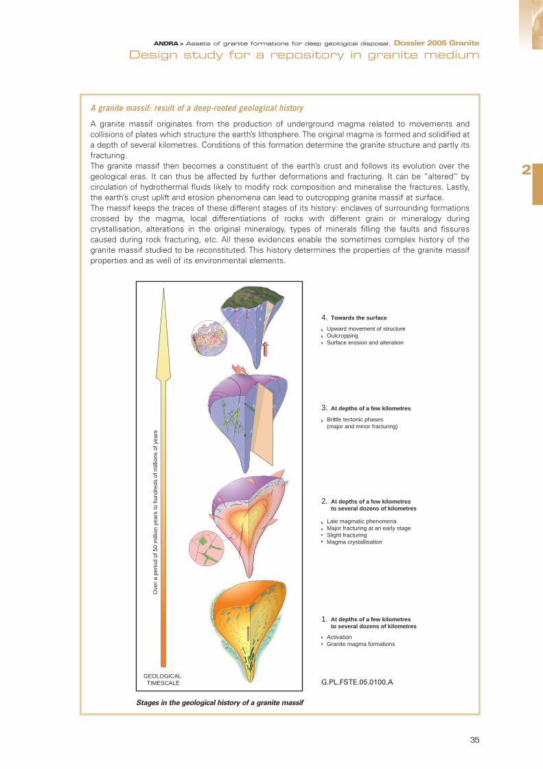
2
Design study for a repository in granite mediumANDRA > Assets of granite formations for deep geological disposal. Dossier 2005 Granite
A granite massif: result of a deep-rooted geological history
A granite massif originates from the production of underground magma related to movements andcollisions of plates which structure the earth’s lithosphere. The original magma is formed and solidified ata depth of several kilometres. Conditions of this formation determine the granite structure and partly itsfracturing.The granite massif then becomes a constituent of the earth’s crust and follows its evolution over thegeological eras. It can thus be affected by further deformations and fracturing. It can be “altered” bycirculation of hydrothermal fluids likely to modify rock composition and mineralise the fractures. Lastly,the earth’s crust uplift and erosion phenomena can lead to outcropping granite massif at surface.The massif keeps the traces of these different stages of its history: enclaves of surrounding formationscrossed by the magma, local differentiations of rocks with different grain or mineralogy duringcrystallisation, alterations in the original mineralogy, types of minerals filling the faults and fissurescaused during rock fracturing, etc. All these evidences enable the sometimes complex history of thegranite massif studied to be reconstituted. This history determines the properties of the granite massifproperties and as well of its environmental elements.
35
4.
3.
2.
1.
G.PL.FSTE.05.0100.A
Ove
r a
perio
d of
50
mill
ion
year
s to
hun
dred
s of
mill
ions
of y
ears
GEOLOGICAL TIMESCALE
Towards the surface
Upward movement of structureOutcroppingSurface erosion and alteration
Brittle tectonic phases (major and minor fracturing)
At depths of a few kilometres
At depths of a few kilometres to several dozens of kilometres
Late magmatic phenomenaMajor fracturing at an early stageSlight fracturingMagma crystallisation
At depths of a few kilometres to several dozens of kilometres
ActivationGranite magma formations
Stages in the geological history of a granite massif
93204_Chap2_GRANITE.qxd 11/04/07 12:52 Page 35

Underground, the rock is “sound” (undisturbed) and variations in composition result from the original geologicalhistory of the granite. On the granite outcrops, between the surface and a hundred metres, the pattern of therock fractures is emphasised by effects of alteration, decompression and then erosion of the rock.
The lithological type and mineralogical composition of the rock can also change from one point to another inthe massif, depending on the mode of granite formation. As a general rule, these variations do not significantlymodify rock mechanical properties and permeability.
More important is the pattern of granite fracturing resulting from its geological history. These fractures meanmore or less marked discontinuity in rock properties which have to be taken into account for repository design.
2.1.3 Slow underground hydrogeological flows Water present in granite faults moves very slowly underground. Movement is driven by hydraulic gradientsrelated to topography. Schematically, the more contrasting the topography, the bigger the gradients. However,the driving force which tends to move massif water is inhibited by high losses of hydraulic head in granitefractures. Irregularities in the detailed geometry of the fracture network prevent water movements.
2.1.4 Underground chemical environment beneficial to a repository
In underground granite, the chemical composition of water is usually balanced with the rock or fractureminerals containing it. The chemical environment is thus a reducing one. Water pH balanced with granite rocknormally approaches neutrality or is slightly basic [7]. These conditions are beneficial both to durability of thematerials which can be used in a repository and immobilisation of most of the radionuclides.
2.1.5 Granite faults and fractures: ability to delay radionuclidesmigration
If granite fractures potentially constitute places of water circulation, possible means of transfer of radionuclidesreleased by the repository, they are also the seat of phenomena likely to immobilise and delay this migration.This major aspect is subject to important studies at international level.In particular, experiments carried out in situ, notably in the underground laboratory in Äspö (Sweden) haveespecially identified the various phenomena involved in delaying radionuclides migration in fractures and haveled to understand clearly their nature. Determination of relations between these phenomena and geological and mineralogical characteristics make itpossible to extrapolate experimental results for various types of granite depending on their own characteristics.
Small-, medium- and large-sized fracturing
Fractures of different sizes run across granite massif. Their number depends on their size. Small-sizedfractures (metric to decametric) are much more numerous than large-sized ones, of kilometric to pluri-kilometric extent. Medium-sized fracturing (decametric to hectometric) makes the transition.Small-sized fractures can affect permeability of the rock where repository structures are to beconstructed. Rock permeability depends on the properties of each of the small-sized fractures, theirdensity and their extent. Small-sized fractures, which can be more or less connected, are usually verypoorly water conducting. Granite permeability, apart from large and medium-sized fractures, is mainly lowor very low and strictly limits water circulation. Large-sized fractures, or faults, are the preferred pathways for water circulation in the granite which doesnot however mean that they contain large quantities of water. The largest faults, if not clogged with clayminerals, are the ones which store most of the granite water.
ANDRA > Assets of granite formations for deep geological disposal. Dossier 2005 Granite
[7] On the other hand, in certain specific contexts, the pH can be slightly acidic.
36
93204_Chap2_GRANITE.qxd 11/04/07 12:52 Page 36

2
Design study for a repository in granite mediumANDRA > Assets of granite formations for deep geological disposal. Dossier 2005 Granite
2.2 Variability of granite within the French geologicalcontext
Although granite repository design is based on generic properties of the granite medium, it also incorporatesspecificities of the particular massif. In the absence of a specific site, Andra has carried out a typologicalanalysis in order to collect data on the variability of French granites. Understanding the differences betweengranites is necessary to take into account these differences in the design and safety analysis in order to ensurethat the selected design options meet the various safety functions.
2.2.1 An analysis method adapted to a siteless study contextVariability of French granite properties has thus been understood through typological analysis based on a largesample. The analysis focussed on the Massif Central and the Massif Armoricain, the two largest areas in theFrench territory of outcropping crystalline basement.
Granites in France
G r a n i t e
G.PL.FSTE.05.0064.A
Parisbasin
Aquitaine basin
Massif Massif ArmoricainArmoricain
Massif Armoricain
Massif Massif CentralCentralMassifCentral
37
93204_Chap2_GRANITE.qxd 11/04/07 12:52 Page 37

Granite areas which, obviously, could not meet the main criteria of the Basic Safety Rule, RFS III.2.f, were ruled outof this study. The areas to be considered have a surface above 20 km2 and are located away from large faults [8]. An inventory of 78 granite areas was thus taken into account for the study.
The analysis initially consisted of describing granite characteristics by evaluating their variations, proven andpotential, and the way in which they can affect repository design options. As granite massifs had seldom beensurveyed in situ underground, excluding a few specific mining areas, their description was based on mappingof their outcropping surfaces. Extrapolation of geometric characteristics and fracturing to the undergroundgranite was carried out on the basis of geological arguments.
Thermal and hydrogeological characteristics were defined from modelling and extrapolation. These were basedon the borehole data available for aspects concerning hydrothermal “alterations” characterisation, thermal fluxdetermination and transmissivity measurements. Sensitivity analyses corresponding to the level of uncertaintyobserved were also carried out based on modelling.
At a second stage, once the main characteristics of the inventory of granite massifs considered weresufficiently known, statistical analysis of their variability within the French geological context could beundertaken. This analysis leads to a granite classification, with respect to each property studied, and to theappraisal of the breakdown of variations in properties of French granites.
Moreover, a comparison of properties of the massifs studied and those of foreign granites provided validationof the use of the data collected in foreign underground laboratories.
2.2.2 Main analysis information:variability of French granite properties for repository design and safety analysis
• Mechanical resistance of granite rock differs according to the types of granite, mainly depending on theirhydrothermal alteration. However, these variations are not normally likely to cause any significant differencesin the granite response to excavation of structures. Differences for repository architectural design are thusminor and only affect detailed design of underground structures.
• Thermal properties variability of French granites is significant enough to be considered in the study of spentfuel disposal. The difference is significant with regards to Fenno-Scandinavian granites where the undergroundtemperature is lower by around 10°C. For C waste, and a fortiori for B5 and B1 waste which is slightlyexothermic, differences between granites do not lead to a significant modification of repository design(dimension).
Thermal properties and repository design basis
The temperature of underground granite and rock conductivity constitute significant parameters forrepository architecture design basis. Repository design must take into account dissipation of heatreleased by C waste and, if the need arises, by spent fuel. In order to better distribute heat sources andcontrol changes in repository temperature, the spacing of packages in the rock can be modified. Initial temperature of underground granite cannot be directly measured without a borehole. Modellingwas thus based on thermal flux mapping in France and thermal conductivity of rocks depending on theirquartz content. Estimations made for a depth of 500 metres have led to uncertainties concerning initialtemperatures of more or less 3°C/3.5°C depending on the massifs.
ANDRA > Assets of granite formations for deep geological disposal. Dossier 2005 Granite
[8] A “buffer” distance of 1.5 or 3 km has been adopted depending on fault size.
38
93204_Chap2_GRANITE.qxd 11/04/07 12:52 Page 38

2
Design study for a repository in granite mediumANDRA > Assets of granite formations for deep geological disposal. Dossier 2005 Granite
Geometry of large-sized fracturing in granite is a significant element for repository architectural design on aspecific site. Depending on the tectonic history of the massif, the fracturing pattern is more or less regular andmassif splitting is more or less pronounced. Analysis of a large number of French granites shows that even ifthe pattern of large-sized fracturing varies between massifs, the distribution of granite blocks where therepository could be constructed complies with rules relatively common to the French massifs studied.
Small-sized fracturing of granite also has a significant impact for repository design. Rock ability to delay andattenuate radionuclide migration will mainly depend on the characteristics of small-sized fractures. Hydraulic conductivity of small-sized fractures is usually low or very low (less than 10-9m/s). In the range of lowpermeability, the values can however vary mainly depending on the granites and types of fracture. They dependon their geometry, orientation and possible natural clogging with minerals and the same goes for radionuclideretention properties by fractures.
…The graph below illustrates the relatively contrasting situations between the different types of Frenchgranite. Initial temperatures at a depth of 500 metres vary between 17 and 30°C. Rock conductivity hasa value of between 2.4 and 3.8 W/m/K.
The design of a spent fuel repository takes into account such differences: the MOX spent fuel footprintcan thus be increased and decreased by 30%.
For C waste and according to the design options proposed, the differences have a far lesser effect onrepository dimensioning. Mechanical resistance considerations limit thermal “gains” for the mostfavourable types of granite. Furthermore, installation of a clay engineered barrier of greater thicknessbetween the packages and the rock for the concepts studied, buffers effects of differences in thermalconductivity between the granites.
Estimation of the temperature at a depth of 500 m for French granite massifs in different regions
39
93204_Chap2_GRANITE.qxd 11/04/07 12:52 Page 39

Clogged and open fractures as seen on granite core samples
The morpho-structural context of granite has also been analysed. Site topography and morphology determinehydraulic gradients, which are the driving force of underground flows. Differences between French massifs aresignificant. Typological analysis has identified three main morpho-structural granite arrangements, which aretaken into account in safety analysis: granite massifs in topographical depression compared to the surroundinggeological formations, domed massifs and sloping massifs. Each type can correspond to more or lessaccentuated topographies.
Morphologies of granite massifs and topography
ANDRA > Assets of granite formations for deep geological disposal. Dossier 2005 Granite
40
93204_Chap2_GRANITE.qxd 11/04/07 12:52 Page 40

2
Design study for a repository in granite mediumANDRA > Assets of granite formations for deep geological disposal. Dossier 2005 Granite
From the hydrogeochemical viewpoint, the inventory and analysis of chemical composition of groundwater inFrench granites show that there is alkaline groundwater and carbo-gaseous one. Carbo-gaseous water ispresent in the Massif Central and can be linked to the geodynamic context and the more or less old volcanicactivity. Alkaline water corresponds to composition close to equilibrium with the granite medium.
These differences in composition do not lead to modify design options principles. In the case of some granitemassifs, they are taken into account by adjusting clay buffer engineered barrier formulations to the ground-water chemical composition.
Examples of groundwater chemical composition in various French contexts (content in mg/l)
In terms of long-term geological evolution of a site, typological analysis of the granite massifs studied confirmsthat most of them are located away from active geodynamic areas, which means unlikely significantmodifications in the long term to their geological arrangements, especially concerning underground fracturing.Climatic changes and erosion can also alter the hydrogeological and topographical context of a site in the longterm. Variations exist between massifs mainly due to differences in morpho-structural context. The analysis hasthus identified the main arrangements encountered within the French context and phenomena which couldcome into play within a timeframe of 10,000, 100,000 and 1,000,000 years. It should be pointed out that, on ascale of 100,000 years, the models do not show any significant differences in evolution between the massifs.Beyond 100,000 years, the situation of each massif is to be specifically taken into account for the study of aparticular site.
3General design options for arepository in granitemedium
In order to fulfil long-term safety functions, the design proposed for a repository in granite medium consists of:
- using a variety of technical procedures to make the most of the beneficial properties of the granite medium,in particular its low permeability and mechanical resistance,
- designing engineered repository components (disposal packages, engineered barriers, backfills, and seals) sothat they contribute to safety functions in terms of complementarity or redundancy with the granite medium.
- adopting design options which help limit repository disturbances of the granite medium.
In addition to the long-term and operational safety, design must meet reversibility requirement, closely linkedto application of the principle of precaution provided for in the law of 30 December 1991. Beyond the possibilityof removing emplaced packages (retrievability), reversibility is based on cautious management of a repositoryin successive stages, which, given the timeframes under consideration, leaves the options open for futuregenerations.
41
Type of
water pH Na K Ca Mg Li Si02 CI SO4 HC03
AlkalineSite 1 8,80 4 400 142 128 1 78 1 790 227 1 010 1 800
Site 2 8,86 5 430 116 850 3,3 55 850 4 200 1 350 2 750
Carbo-
gaseous
Site 3 6,64 95 500 4 360 1 570 1 940 1 420 1 700 105 100 6 500 29 500
Site 4 6,80 41 700 635 3 550 3 500 590 770 1 200 220 57 100
Site 5 6,67 39 100 2 420 15 100 16 100 770 2 100 56 600 2 600 40 200
93204_Chap2_GRANITE.qxd 11/04/07 12:52 Page 41

These principles lead to adopting various technical measures for repository architecture and dimensioning,choice of materials for engineered components and disposal processes. Some measures, architectural inparticular, are common to different categories of waste (B and C) and to spent fuel; others, as for instancedesign of engineered components, are specific to each waste category.
3.1 Making the most of favourable granite propertiesThe granite medium is characterised as a very low permeability rock, with high capacity for radionuclideretention and mechanically resistant. Since granite is intersected with fractures liable to conduct water, makingthe most of its favourable properties requires adaptation of repository architecture to this fracturing.
3.1.1 Architecture with compartmentalisation,adapted to granite fracturing
Repository architecture is organised into different zones by major categories of packages: B waste, C wasteand spent fuel. These zones are sufficiently far apart to avoid interaction between different types of waste,particularly from a thermal or chemical viewpoint. Compartmentalisation of each repository zone also reducesquantities of waste and radionuclides which would be affected in cases of system failure or intrusion.
Apart from these design principles, repository architecture and compartmentalisation is imposed by granitefracturing.
• Construction away from faults
At repository scale, repository zones for the various categories of waste are constructed away from majorfaults of the granite massif.
Each repository zone is divided into modules grouping together a series of cavities (the disposal cells) for thesame type of waste. Modules are located in granite blocks not intersected by large- or medium-sized faults,considered as since significantly water conductors. One of the basic principles of a repository in a granitemedium is to construct disposal cells in the very low permeability rock. This does not mean that there can beno fracturing whatsoever in the rock but that small-sized fractures which may exist in disposal cell walls do notconduct water or in small quantities. Therefore water flow which might come into contact with packages isminimal.
Disposal cells are of a dead-end type (therefore with only one access to repository drifts), thus limitingpossibilities of circulation of water coming from the drifts.
These principles regarding repository siting and architecture meet the requirements laid down in the BasicSafety Rule III.2.f, which states:
”Repository in geological formations must be located in the case of crystalline mediums, within a host-blockexempt from major faults, as the latter are likely to be potential pathways of hydraulic movement. Disposalmodules must be protected from medium-sized fracturing, although this may be crossed by access structures”.
• Construction of modules with respect to waste heat transfer
At the module scale, the principle of adapting architecture to fracturing works differently for each type of waste.The footprint required for different types of packages may necessitate implementation of different options.
The inexistent (or low) heat transfer by B waste makes possible a design with compact disposal cells andtherefore requiring only a low volume of granite. B waste disposal thus requires a little footprint and adjustmentof architecture to granite fracturing is eased. Disposal modules are built so as to avoid fractures likely to causeadvective water circulation.
ANDRA > Assets of granite formations for deep geological disposal. Dossier 2005 Granite
42
93204_Chap2_GRANITE.qxd 11/04/07 12:52 Page 42

C waste and spent fuel thermal characteristics define disposal modules dimensioning and lead to such largefootprints that it is not possible to avoid the intersection of a module by a fracture, potentially water conducting [9].Repository architecture must also be adapted to two levels of fracturing. Size of disposal cells allows them tobe built in a very low permeability granite rock with minimal fracturing. Modules are installed in granite blocks,avoiding fractures which would let in too much water, the medium-sized fracturing as mentioned in RFS III.2.f.
Conceptual diagram for construction of repository structures in relation to fracturing
The large volume of granite rock available underground, for a repository between 300 and 1000 metres deep,allows for flexibility in adapting architecture to granite fracturing. General repository architecture can then bedesigned on one or more levels.From a functional point of view, such architectural arrangements enable the repository to fulfil a primaryobjective of preventing advective water flow within the underground installations. As regards disposal cells, thishelps to facilitate a diffusion transfer system. Water flow rates are limited in the module drifts. In addition, therepository is located away from regional faults, safe from major water circulations. Such architectural arrangements also facilitate other repository functions, limiting release of radionuclides bydisposal cells and their migration towards the environment.
3.1.2 A disposal process enabling “ongoing” surveying andcharacterisation of granite blocks where modules areconstructed
Adapting repository architecture to fracturing means possessing detailed and accurate knowledge of thegranite host rock characteristics. The surveying strategy may include several stages:
- surveying and characterisation operations from the surface, or from underground structures (geologicalmedium qualification underground facility), in order to define the granite structure where the repository is tobe built. An iterative approach between safety analysis and the various phases of granite site survey, on thesurface and then underground, defines criteria for exclusion of faults (or fractures) which may or may not beintersected by repository connecting drifts and access drifts to modules and disposal cells,
0 1 2 km
0 200100
G.PL.FSTE.05.0020.A
Regional faults Repository
The repository is built awayfrom the regional faults.
Ramp
Non-exothermic or slightly
exothermic B waste module
A compact architecture built away from the water-conducting faults
Sand
Exothermic C waste
and spent fuel module
Disposal boreholes located in slightly fractured granite rock
The connecting drifts intersecting sealed water-conducting faults
Legend
Major and medium fracturing outside repository modules
Sealing
B waste disposal tunnels
C and CU waste disposal boreholes
2
Design study for a repository in granite mediumANDRA > Assets of granite formations for deep geological disposal. Dossier 2005 Granite
43
[9] Taking into account volumes and heat transfer, spent fuel disposal is more demanding in terms of footprint than C waste disposal.
93204_Chap2_GRANITE.qxd 11/04/07 12:52 Page 43

- on this basis, the process includes in situ characterisation of host-granite blocks for disposal modules beforepackage emplacement. This stage of granite “ongoing” characterisation during the staged repositoryconstruction finalises module architecture and distribution of disposal cells in the granite according tofracturing.
Such a strategy aims at adapting repository architecture as best as possible to granite fracturing and to ensurethat proposed design concepts fulfil their functions effectively as regards control of water circulation in therepository
3.2 Design of engineered components,complementary and redundant with the granitemedium for long-term safety
At the scale of both the repository as a whole and the disposal cell, several arrangements are possible toensure complementarity and redundancy between the granite medium and repository engineered componentswith respect to long-term safety. They particularly concern repository architecture and choice of materials forengineered components (disposal packages, engineered barriers, backfills and seals).
3.2.1 Multiple sealing of underground installations Connecting drifts and access drifts to modules and disposal cells are likely to intersect water-conductingfractures. In order to limit water circulation within the repository, seals are installed at various levels of theunderground installations.
In the case of disposal cells, water may come from drifts serving them. Drifts are likely to be crossed by a morewater-conducting fracturing that the cell rock wall one. The ‘dead-end’ architecture of cells, their constructionin granite rock of very low permeability, and low permeability ‘plugs’ at cell heads limit water circulation andaims at establishing a transfer system in the cells governed by diffusion phenomena.
At the repository module scale, water circulation is limited by:
- very low permeability seals installed in drifts to cut off modules from water coming from any possibleintersecting faults,
- backfills of sufficiently low permeability in module drifts.
Disposal cell seals and plugs are made of swelling clay (bentonite), of very low permeability over long periodsof time. Backfills may also incorporate clay materials to ensure sufficiently low permeability.
At the repository scale, connecting drifts between modules as well as structures between surface andunderground are backfilled. Seals are installed in access structures where they intersect water-conducting faults.
3.2.2 A physico-chemical environment suitable for waste packages
Disposal cell design seeks to provide a suitable physico-chemical environment for waste and packages in orderto control changes in state over time and limit release of radionuclides.
Such an environment is ensured by the materials used for waste over-packs, the choice of which depends ontype, volume, radiological inventory and chemical nature of the waste, as well as by engineered barriers.
For B waste containing metal elements (B1, B3, B4 and B5 reference packages), the aim is to limit corrosionby providing a favourable chemical environment (reducing potential, pH 10 to 12.5), in particular by usingconcrete for waste over-packs. For bitumised B waste, the aim is to maintain, on the long term, bitumenconfinement properties (B2 reference package) by controlling chemical conditions and temperature (between20 and 30°C).
For C waste and spent fuel, emplacing clay buffers between packages and the granite rock attenuates chemicalinteraction between packages and granite groundwater.
ANDRA > Assets of granite formations for deep geological disposal. Dossier 2005 Granite
44
93204_Chap2_GRANITE.qxd 11/04/07 12:52 Page 44

2
Design study for a repository in granite mediumANDRA > Assets of granite formations for deep geological disposal. Dossier 2005 Granite
3.2.3 Disposal packages which are leak-tight or of very lowpermeability over a sufficiently long period of time
In order to ensure complementarity with the geological barrier, primary packages are inserted in additionalcontainers, to constitute disposal packages. A study has been carried out in order to ensure their leak-tightnessor very low permeability over sufficiently long periods of time, which depends on types of waste and theirradiological inventories.
A concrete disposal package has been chosen for B wastes. For some types (B1 and B5 packages, which havemajor radioactive content and do not release gas), disposal packages have long-term confinement properties(around ten thousand years). This performance is achieved by using a specially adapted concrete mix (with verylow permeability and porosity) and a specific design (method of closing). This type of container limits waterreaching primary packages as well as radionuclide release for this period of time.
For C waste packages, the aim is to prevent water from coming into contact with the glass for several thousandyears. This period concerns the thermal phase (i.e. the period when the temperature at the heart of the glassis over 50°C) during which glass alteration phenomena by water are accelerated. The proposed design is basedon a very thick steel container.
For spent fuel, a copper container is proposed, with long term leak-tightness property (up to several hundredthousand years). In contrast to C waste, radionuclides are not trapped in a confinement matrix (a fraction of theradionuclides is released upon contact with water, and the remainder is released gradually as the uranium oxidematrix dissolves). This option is based on the ‘KBS-3’ copper container, a concept adopted in Sweden (SKB)and Finland (Posiva). It was adopted by Andra at this generic design phase. Site data would justify revision ofthis option if adaptation of architecture to granite massif fracturing and engineered structures (backfills andseals) allow sufficiently long time transfer in the geological medium to ensure radioactive decay ofradionuclides.
3.3 Limiting granite disturbance caused by the repository
While repository design aims to take into account the favourable properties of granite, it should be ensuredthat repository construction and its long-term evolution do not aversely affect the properties of the granitemedium. The various arrangements studied involve structure dimensioning, choice of materials for engineeredcomponents and the disposal process.
3.3.1 Design limiting mechanical and thermal disturbance Granite is a mechanically resistant rock. The structures (drifts and cells) are dimensioned to ensure mechanicalstability in the long term.
Heat released by C waste and, if need arises also by spent fuel, means a temperature rise in the disposal cellsand surrounding granite. In order to control the thermal phenomena induced, the aim is to keep thetemperature in the cells lower than 100°C (and therefore in the rock). In practical terms, a maximumtemperature of 90°C has been adopted for the hottest point in the swelling clay buffers for C waste cells andat the surface of spent fuel copper containers.
The essential parameters for repository architecture dimensioning in order to limit the temperature are on onehand, the number of disposal packages per cell and on the other hand, the spacing in between disposal cells.The C waste and spent fuel repository zones footprint is mainly subordinate to these thermal considerationsand the thermal power released by the packages when emplaced in the repository.
45
93204_Chap2_GRANITE.qxd 11/04/07 12:52 Page 45
3.3.2 Disposal process limiting hydrogeological andhydrogeochemical disturbance of the host granite massiffor underground installations
Excavation of underground installations drains off granite groundwater and disturbs initial hydrogeology. Asgranite is only slightly permeable, this disturbance mainly affects the most water-conducting faults andfractures. In order to limit groundwater draining from the granite and by extension the quantities of pumpedwater while excavating the underground installations, it can be envisaged to resort to injection techniques forthe most water-conducting faults and fractures intersected by the structures.
After a transient phase of disturbance related to underground installations excavation, equilibrium betweenwater drainage and re-supply is established within the granite massif.
Appropriate management, depending on the granite hydrogeological context, of excavation of repository zones,their operation and then their closure constitutes then a means of limiting hydrogeological andhydrogeochemical disturbance of the granite.
3.4 Adaptation of design arrangements to long-term safety functions
The various options proposed contribute to one and /or the other of the major functions of a repository:
- the function “preventing water circulation in the repository” is mainly fulfilled by architectural and sealingarrangements. Repository architecture is adapted to granite fracturing,
- the function “limiting the release of radionuclides and immobilising them within the repository” is mainlyfulfilled by systems implemented near the packages in order to permanently ensure favourable environmentalconditions to the protection of waste and immobilisation of radionuclides released,
- the function “delaying and reducing radionuclides migration” makes the most of all technical measuresadopted within the design options: structure design basis, choice of structure and package materials.
ANDRA > Assets of granite formations for deep geological disposal. Dossier 2005 Granite
46
93204_Chap2_GRANITE.qxd 11/04/07 12:52 Page 46

2
Design study for a repository in granite mediumANDRA > Assets of granite formations for deep geological disposal. Dossier 2005 Granite
Technical measures and long-term safety functions for a repository in granite medium.Contribution of technical measures to the function:XXX: essential;XX: significant;X: secondary
Safety functions
Design principles
Technical measures
Preventing watercirculation in the
repository
Limiting release ofradionuclides and
immobilising them inthe repository
Delaying andattenuating
radionuclidesmigration
Making the most of favourableproperties ofgranite medium
Architectural Constructing cells in very low permeability granite rock
XXX X XX
Constructing modules in the “blocks”apart from water conducting faults XXX X XX
Constructing the repository away from regional faults XXX X XX
Disposal process Ongoing characterisation of granite blocks
XXX X XX
Designingengineeredcomponentscomplementary toand redundant withgranite medium
ArchitecturalMultiple sealing of structures (cells, modules, drifts, surface-bottomconnecting structures)
XXX XX XXX
MaterialsA physico-chemical environmentbeneficial to packages and waste:engineered barriers and overpacksadapted to types of waste
XXX X
Disposal packages (containers,overpacks, etc) leak-tight or onlyslightly permeable for sufficiently longperiods of time depending on types ofwaste
XXX XX
Limiting granitedisturbanceinduced by the repository
Design basis Structure dimensioning ensuringlong-term mechanical stability
XXX XXX
Structure thermal dimensioning forcontrol of phenomena caused bystructure temperature rise
X
MaterialsDisposal packages and engineeredbarriers whose alteration does notsignificantly disturb granite retentionproperties
XXX
Disposal process
Disposal process managed so as to limit disturbance of granitehydrogeological andhydrogeochemical characteristics
XXX XX XXX
47
93204_Chap2_GRANITE.qxd 11/04/07 12:52 Page 47

ANDRA > Assets of granite formations for deep geological disposal. Dossier 2005 Granite
3.5 Integrating reversibility In addition to operational and long-term safety, repository design must meet the reversibility requirement.Reversibility is related to a cautious and staged management of a possible repository which, given thetimeframes considered, leaves the options open for next generations.
Reversibility requirement involves, over the course of time, human presence, monitoring and maintenanceactivity which do not put at stake, whatsoever, long-term safety, the primary aim of the repository. But rather,based on a cautious and gradual management of the disposal process, reversibility can contribute to improvingthe confidence in long-term safety.
Reversibility requirement was at the heart of the analyses carried out for the study of a possible repository ingranite medium. The design approach implemented by Andra aimed at proposing generic design optionsfulfilling the reversibility requirement.
Beyond the ability to retrieve disposed packages (retrievability), reversibility can be defined as the possibility ofgradual and flexible management of the repository which leaves future generations with freedom to decide.With this aim in mind, the disposal process can be broken down into a succession of stages to be performed,which provides, from the construction of the initial modules up to closure of a module or of a repository zone,the possibility of waiting and observation time, before deciding to go on to the next stage or reverse theprocess. The completion of a stage is not a definitive decision, but a justified choice, based on thoroughunderstanding of scientific, technical, economic, social and environmental parameters and the consequencescaused by going from one stage to another.
In this perspective, repository design therefore considers the three aspects of reversibility:
- architectural arrangements beneficial to a gradual repository management,
- technical measures for going backward to the various disposal stages,
- means of observing repository status and its evolution at any time in the process.
3.5.1 Repository architectures incorporating and fostering reversibility
Simplicity and robustness of the concepts, durability of materials, modular design: repository architecturesproposed by Andra incorporate reversibility requirements and facilitate its application.
• Simple and robust disposal concepts
Concepts proposed by Andra at this stage of the study are, by principle, simple and robust. Simplicity is basedon the concern for technical feasibility and control of performance. Mechanical resistance of granite rockespecially allows to limit support systems in structure design. Simplicity of options proposed by Andra facili-tates the description of their evolution over time as well as their modelling. Robustness is based on resistanceof the concepts in terms of safety and necessary scientific knowledge.
• Durable materials and systems to facilitate potential withdrawal of the packages
The aim of facilitating packages retrievability by future generations has led Andra to give priority to durablematerials for packages and structures (concrete, steel, etc.), since their good preservation is the basic conditionfor reversibility. Their durability in a repository environment may be estimated at several centuries.
In addition, several systems combine to facilitate the reversible management of the repository and the possibleretrievability of the packages: for example, regrouping the packages in standardised over-packs, identicalhandling systems for package emplacement and retrieval, incorporation of handling space in between thepackages and/or between the packages and disposal cell walls.
• Modular design of underground installations for flexible management and changes in design
The architectures proposed are of modular design meaning that they enable the repository to be managed ina flexible way for example, construction and operation in stages thus facilitating incorporation of lessons learntfeedback.
48
93204_Chap2_GRANITE.qxd 11/04/07 12:52 Page 48

2
Design study for a repository in granite mediumANDRA > Assets of granite formations for deep geological disposal. Dossier 2005 Granite
Each package category (B, C and CU) is received in an assigned repository zone, constructed, operated andclosed independently. Each repository zone is designed to be built and operated gradually as successive cellsub-assemblies. The closure is designed in the same way as for operation in a gradual manner organised intoseveral stages: closing of cell sub-assemblies, which can be carried out at the same time as the creation ofnew sub-assemblies, closing of access to this sub-assembly, and then of the repository installations specificto this waste category and lastly of all installations.
As the repository is being developed in stages, new structures can be designed taking advantage of thelessons learnt and knowledge acquired during operation and observation of previous structures, as well as oftechnical progress carried out otherwise. It is as well possible to incorporate data from social, technical andscientific backgrounds.
3.5.2 Technical feasibility of reversing the process Andra has studied the technical feasibility of reversing the process for the various repository stages:technological resources, operating conditions and necessary precautions.
The repository is therefore designed to allow packages to be retrieved in the first stage by simply reversing theprocess of their emplacement in the cell (as in a storage facility). For later stages, Andra has incorporatedarrangements for being able to gain access again to the installations which are closed and install the equipmentrequired to retrieve the packages, would such a decision occur.
3.5.3 An observation programme supporting reversiblerepository management
Keeping options open during the repository process implies knowledge of its evolution and situation at alltimes, therefore requiring constant observation and implementation of the necessary measurement resourcesand systems. Andra has studied the possibilities of integrating measuring sensors in the structures withoutdisturbing repository operation and safety.
In addition to the monitoring measures related to operational safety, the role of this observation programme isto check that repository evolution matches forecasts, to propose, if needed, actions to conserve the variousmanagement options and to compile lessons learnt in order to improve repository design and management.The data thus acquired will contribute to improve modelling and to increase the reliability of forecasts.
Abroad: consensus for a stepwise approach
Concerted action within the European Union has shown the relevance of sub-dividing the repositoryprocess into stages to understand reversibility and provide a gradual framework for decision making. In 2002, the OECD Nuclear Energy Agency (NEA) also emphasised the fact that the reversibility approachin successive stages in line with a cautious and flexible process is considered “good practice”. The NEAalso insists on the need for making arrangements of an institutional, organisational, regulatory, political andfinancial nature as a complement to technical measures to implement repository retrievability andreversibility. In the USA, the staged approach presented by the National Research Council (NRC) offers decision-makersan as large as possible range of options at each stage and is somehow similar to Andra’s one. The NRChighlights the technical as well as the social, political and economic benefits of this approach compared toa “linear” approach.
49
93204_Chap2_GRANITE.qxd 11/04/07 12:52 Page 49

50
ANDRA > Assets of granite formations for deep geological disposal. Dossier 2005 Granite
95467_Chap3_Granit.qxd 11/04/07 14:12 Page 50

51
ANDRA > Assets of granite formations for deep geological disposal. Dossier 2005 Granite
3Understanding and modelling granitep.52 > 1. Surveying a granite site
p.54 > 2. Geological modelling
p.64 > 3. Hydrogeological and hydrogeochemical modelling
and transfer simulations
p.75 > 4. Geomechanical modelling
p.79 > 5. Considering very long-term geodynamic evolution
and climate change: geo-prospective study
95467_Chap3_Granit.qxd 11/04/07 14:12 Page 51

As a host geological formation for a repository, granite involves specific repository design constraints onaccount of its structure and properties. A site must therefore be surveyed and characterised with sufficientaccuracy in order to adapt design arrangements to the structure and properties of the granite massif studied.
1Surveying a granite site
The purpose of exploratory work on a granite massif is to collect site data and develop models with a view todesign the architecture of a repository and demonstrate its suitability in terms of safety and reversibilityobjectives. The work is carried out over several stages through an iterative approach associated with designstudies and safety analyses.
As a result, disposal concepts can be adjusted, at every stage, to the site and the uncertainties to beconsidered in the safety analyses can be reduced.
1.1 The aims of surveying a granite siteThe geological description of a granite massif is based on the integration of data relating to the structure of thegranite studied, especially fracturing, and the mineralogical and geochemical nature of the rocks forming themassif.
The hydrogeological and hydrogeochemical properties of the massif are also essential components incharacterising a granite site. They concern the general hydrogeological context of the site, hydraulic parameterscontrolling water circulation in the fractures and hydrogeochemical factors governing radionuclide transfer andretention.
The geomechanical and thermal properties of granite also need to be considered on dimensioning therepository; they must therefore be characterised throughout the exploratory phases.
Understanding granite
ANDRA > Assets of granite formations for deep geological disposal. Dossier 2005 Granite
52
95467_Chap3_Granit.qxd 11/04/07 14:12 Page 52

3
Understanding and modelling granite
Gathering site data constitutes the first step of a granite massif characterisation. Then, the second step, dataintegration, requires to analyse the consistency in between the various disciplines involved and to developmodels representing the distribution of the granite’s properties:
- geological models representing the structure of the granite massif studied and its fracturing in threedimensions,
- hydrogeological and hydrogeochemical models to simulate water circulation in the granite fractures andradionuclide transfer and retention,
- geomechanical models describing the geomechanical context of the site and the behaviour of the granite inresponse to disturbance, notably the thermal one, caused by a repository.
1.2 A staged approachCharacterising the properties of granite involves an approach and techniques which take account of the largevolume of rock to be surveyed and the specific features of a fractured medium. This requires work on variousscales, both on the surface and underground.
Some characteristics of granite cannot, with the techniques available, be characterised directly from thesurface. For instance, the exact fracture distribution can only be determined in situ underground. Beforeunderground surveys, the techniques adopted from the surface can be used to develop realistic fracturedistribution models which will subsequently be improved in situ.
Before constructing a repository, the site surveying approach consists of gradually building up detailedknowledge of granite through two main stages:
- surface exploration to develop the models required for an initial assessment of the site’s suitability for theinstallation of a repository. The absence of site characteristics ruling out repository feasibility is verified on thebasis of design studies and safety analyses. A further aim of this stage is to specify the layout and researchprogramme of an underground laboratory for in situ characterisation of the granite;
- qualification through underground structures to assess the suitability of the site for a repository. The workconsists of specifying the geological, hydrogeological and geomechanical models of the granite site andmodels of radionuclide transfer and retention in the fractures. Site qualification is based on the design studiesand safety analyses. This results in particular in the siting criteria for repository structures within the graniterock.
During construction of the repository, the precise adjustment of the repository architecture to the site’scharacteristics, especially the fracturing of the granite and the criteria defined during the previous stage,requires to carry out “ongoing” surveying and characterisation work.
Stages of surface exploration and underground laboratory qualification
ANDRA > Assets of granite formations for deep geological disposal. Dossier 2005 Granite
53
95467_Chap3_Granit.qxd 11/04/07 14:12 Page 53

2Geological modelling
The geological modelling of a site aims at representing the structure of the studied granite in three dimensions(3D) and on various scales. Geological models act as a support for the hydrogeological, hydrogeochemical andgeomechanical modelling of the site and the simulation of any radionuclide transfers in the granite which is thebasis for the performance assessment of the repository.
2.1 What geological objects ?A granite massif is a composite geological formation, which is the result of a multistage geological history:
- the genesis, emplacement and crystallisation of granite magma at variable depths according to the type ofgranite;
- one or more deformation and fracturing phases during and after granite emplacement;
- the rising of the geological basement and the erosion of overlying formations leading to outcropping granite.
Each phase in this geological history impacts on the composition and structure of a massif. The rock itself andits geochemical nature, mineralogy and homogeneity reveal the original history of the granite and thesolidification phases.
Granite emplacement and the deformation phases are accompanied by hydrothermal fluid circulationscharacterised by mineralogical transformations of the granite mass or its fractures. The structure and fracturingof the granite provide indications about the various phases of tectonic deformation affecting a massif during andafter granite emplacement and crystallisation.
Some rocks, originating more or less from the magma creating the granite, intersect the granite rock in the formof veins: fine-grain aplites, large-mineral pegmatites, basic dolerites, etc. These rocks also bear witness to thevarious phases in the history of the massif and often constitute guidelines to the modelling of the structure ofthe granite massif.
The surface parts of the granite are also an important element of the massif structure. Resulting from erosionphenomena leading to granite outcrops, they are altered and generally much more permeable than deep granite.They can form a reservoir of rainwater feeding the hydrogeological system of the deep granite (cf. 3.3).
Each one of these elements forms a component of the geological model to be produced and developed over thesuccessive stages of surveying and characterising the granite.
2.1.1 Granite rockA granite massif is, in the majority of cases, composite; in other words, the mineralogical nature of the constituentrock varies from one point of the granite to another. This is explained by the different primary origins of themagmas or by differentiation phenomena in the course of granite emplacement and solidification.
On a massif scale, modelling consists of defining the major composite granite structures of the massif. Forexample, the Charroux-Civray granite massif in the Vienne district, studied by Andra from 1994 to 1996, originatesfrom various kinds of magma which were assembled as the massif was emplaced. Similarly, the Äspö laboratoryin Sweden is located in a massif composed of two dominant types of granite: Ävrö granite and Äspö granodiorite.
ANDRA > Assets of granite formations for deep geological disposal. Dossier 2005 Granite
54
95467_Chap3_Granit.qxd 11/04/07 14:12 Page 54

3
Understanding and modelling granite
Geological map of Äspö
At the repository scale, modelling consists of representing the relationships between the various components ofthe massif in three dimensions (3D). It aims to identify how the differences in nature between the variouscomponents of the granite can impact on the design of a repository and the safety analyses. For example, itinvolves ascertaining whether mineralogical differences significantly alter the thermal or hydraulic properties of therock and assessing whether fracturing varies according to the nature of the various components. From this point ofview, their contacts are important markers. These observations, in return, indicate the intensity of the deformationsto which the rock is subjected.
The integration of data on the various scales contributes to the understanding of the geological history of thegranite. Data consistency is an evidence of the soundness of the 3D geological models.
2.1.2 Fracturing of granite As a result of its genesis and geological history, granite is a fractured medium. The fractures are the pathwayswhere water flows through the granite. They are therefore potential vectors for the transfer of radionuclidesfrom the repository to the environment. Their detection and 3D representation are an essential objective ofgeological modelling.
• Scales of fracturing
Fracturing of granite is observed on very different scales: from a crustal scale with the major faults structuringthe subsoil basement, to micro-fractures on a mineral scale and observed under a microscope.
ANDRA > Assets of granite formations for deep geological disposal. Dossier 2005 Granite
55
95467_Chap3_Granit.qxd 11/04/07 14:12 Page 55

Scales of granite fracturing
Major fracturing and minor fracturing are also differentiated by the way in which they are treated –deterministically or statistically:
- small fractures result from thermal “shrinkage” during magma solidification or subsequent deformationphases. Apart from zones of major granite deformation, they generally conduct very little water. Thecharacterisation and modelling of minor fracturing are based on a statistical approach. Fracturing model inputis the systematic geological survey which provides distribution laws of their main characteristics in the granite:size, orientation and dip;
- large fractures, or faults, always result from significant deformations in the granite massif during the tectonicphases. They are often a composite of several lower-order fractures. The mode and intensity of the fracturecan vary from one point of a massif to another and from one massif to another, which leads to various fracturemodels dividing the granite massif up into “blocks” of different shapes. In order to detect and model them,large fractures and faults are based on a deterministic approach during the exploratory phases: they aregenerally large enough to be identified one by one and to form the structuring elements of granite modelling.
Details of the structure of a large fault on various scales
LENGTH ANALYSIS TYPOLOGY
Crustal faults
>100 kmRegional faults
10 kmLocal faults
1 km
1 hm
1 dam
1 m
1 dm
1 cm
1 ìm
FRACTURING DOMAIN
MAJOR
FRACTURING
REGIONAL
FRACTURING
DETERMINISTIC
LOCAL
FRACTURING
HECTOMETRIC
FRACTURING
Hectometric
faultsMEDIUM
FRACTURING
Limit depending on surveying
progression
Fissures
Joints
Small faults
Gashes
and fissuresSTATISTICAL
MINOR FRACTURING
MICRO FRACTURINGMicrofracturing
Microfissuring
ANDRA > Assets of granite formations for deep geological disposal. Dossier 2005 Granite
56
95467_Chap3_Granit.qxd 11/04/07 14:12 Page 56

3
Understanding and modelling granite
- the treatment of “medium” fractures forms the transition between these scales of fracturing. Its treatmentwill change as a granite site is surveyed. Treated statistically in the initial stages, it is based on a deterministicapproach during phases detailing the structure of the granite on the scale of a repository module. This isparticularly the case during the “ongoing” survey work while the repository structures are excavated.
• Mineralogy of faults and fractures
Faults are the result of shear breaking of the rock, causing slippage and partial crushing. Faults are thereforecomposed of elements of granite rock which are crushed (“brecciated”) or even transformed into clay (“claygouge”) depending on the intensity of the deformation. Furthermore, the hydrothermal fluid circulationsaccompanying the fracturing phases in the granite mean the precipitation of specific minerals inside the faults.The mineralogical composition of the fracture-filling materials bears witness to various events at the origin ofthe granite and the physical and chemical conditions governing its structuring. The modelling of fracturing therefore distinguishes between various families of fractures according to theirgeometry and the mineralogy of their filling materials.
View of a fracture plane
2.2 MethodsThe surveying techniques of a granite site are adapted to the various stages of the approach and to thecorresponding objectives. They combine:
- geological surveys through the direct observation of the granite either on outcrops at the surface, on coresamples from boreholes, or on walls of underground structures;
- geophysical surveys providing images of the substratum on various scales.
2.2.1 Surface or underground geological surveys
Surface geological mapping is used to complete existing geological maps by outcrop surveys, the processingand interpretation of aerial photographs, satellite images and digital terrain models. It is an input for theproduction of 3D geological models from interpreted geological cross-sections.
ANDRA > Assets of granite formations for deep geological disposal. Dossier 2005 Granite
57
95467_Chap3_Granit.qxd 11/04/07 14:12 Page 57
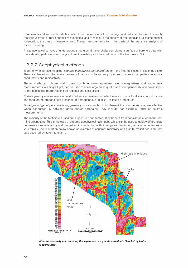
Core samples taken from boreholes drilled from the surface or from underground drifts can be used to identifythe various types of rock and their relationships, and to measure the density of fracturing and its characteristics(orientation, thickness, mineralogy, etc.). These measurements form the basis of the statistical analysis ofminor fracturing.
In situ geological surveys of underground structures, drifts or shafts complement surface or borehole data withmore details, particularly with regard to rock variability and the continuity of the fractures in 3D.
2.2.2 Geophysical methodsTogether with surface mapping, airborne geophysical methods often form the first tools used in exploring a site.They are based on the measurement of various substratum properties: magnetic properties, electricalconductivity and radioactivity.
These methods, whose main ones combine aeromagnetism, electromagnetism and radiometrymeasurements in a single flight, can be used to cover large areas quickly and homogeneously, and are an inputto the geological interpretations on regional and local scales.
Surface geophysical surveys are conducted less extensively to detect variations, on a local scale, in rock natureand medium heterogeneities: presence of homogeneous “blocks” of faults or fractures.
Underground geophysical methods, generally more complex to implement than on the surface, are effectivewhen conducted in between drifts and/or boreholes. They include, for example, radar or seismicmeasurements.
The majority of the techniques used are largely tried and tested. They benefit from considerable feedback frommine prospecting. This is the case of airborne geophysical techniques which can be used to quickly differentiatebetween zones where physical properties, in connection with lithology and fracturing, remain homogenous orvary rapidly. The illustration below shows an example of apparent resistivity of a granite massif deduced fromdata acquired by aeromagnetism.
Airborne resistivity map showing the separation of a granite massif into “blocks” by faults
(Cogema data)
ANDRA > Assets of granite formations for deep geological disposal. Dossier 2005 Granite
58
High resistivity block
Faults
Less homogenous block
95467_Chap3_Granit.qxd 11/04/07 14:12 Page 58

3
Understanding and modelling granite
Other techniques have undergone more specific developments for repository studies, especially fractureexploration techniques, which provide sufficiently precise imaging of granite at various scales. In this respect,Andra has tested various electrical, electromagnetic and seismic methods with Posiva at the Olkiluoto site inFinland. Complementarity of these methods for the detection of faults or other geological objects, such ascontact between rocks of different kinds, could be appraised through such tests. They have specified the fieldof application of methods to be implemented from the surface, boreholes or underground structures, at thevarious stages of exploration. The applicability of the methods tested in Finland to the French geological contexthas also been verified.
Testing geophysical methods with Posiva in Finland
In the framework of a cooperation agreement signed in 2002 to develop surface methods ofcharacterising a crystalline site, Andra and Posiva tested two geophysical methods at the Olkiluoto sitein 2002 and 2003: the first concerned electrical and electromagnetic methods carried out from thesurface, the second, seismic methods using deep boreholes.
• Joint acquisition and interpretation of electrical and EM data
This work, combining conventional borehole electrical surveys with electromagnetic multifrequencymeasurements, was carried out to explore the 0-500 metre depth range. The electromagnetic measurements were carried out over a 3400-metre long line across the Olkiluotoisland using both in-line array and broadside array configurations for the transmitter-receiver stations (seeillustration below). To best cover the 0-500 metre range, various transmitter-receiver spacings wereadopted: 200, 500 and 800 metres.
Location of the electrical (LINE 1 West, LINE 1 East, LINE 2 and LINE 3) and electromagnetic measurement lines(in-line array: blue squares with 200 metres station spacing, broadside array: red with 200 metres and 500 metresspacing, light blue with 800 metres spacing) (kilometric grid). Inset, the measurement system.
The electrical and electromagnetic data underwent specific processing operations and were interpreted,first separately and then jointly. The final stage of interpretation integrated the borehole resistivitymeasurements and the comparison of the electrical and electromagnetic measurements with the resultsof earlier geological and geophysical surveys.
…
ANDRA > Assets of granite formations for deep geological disposal. Dossier 2005 Granite
59
95467_Chap3_Granit.qxd 11/04/07 14:12 Page 59
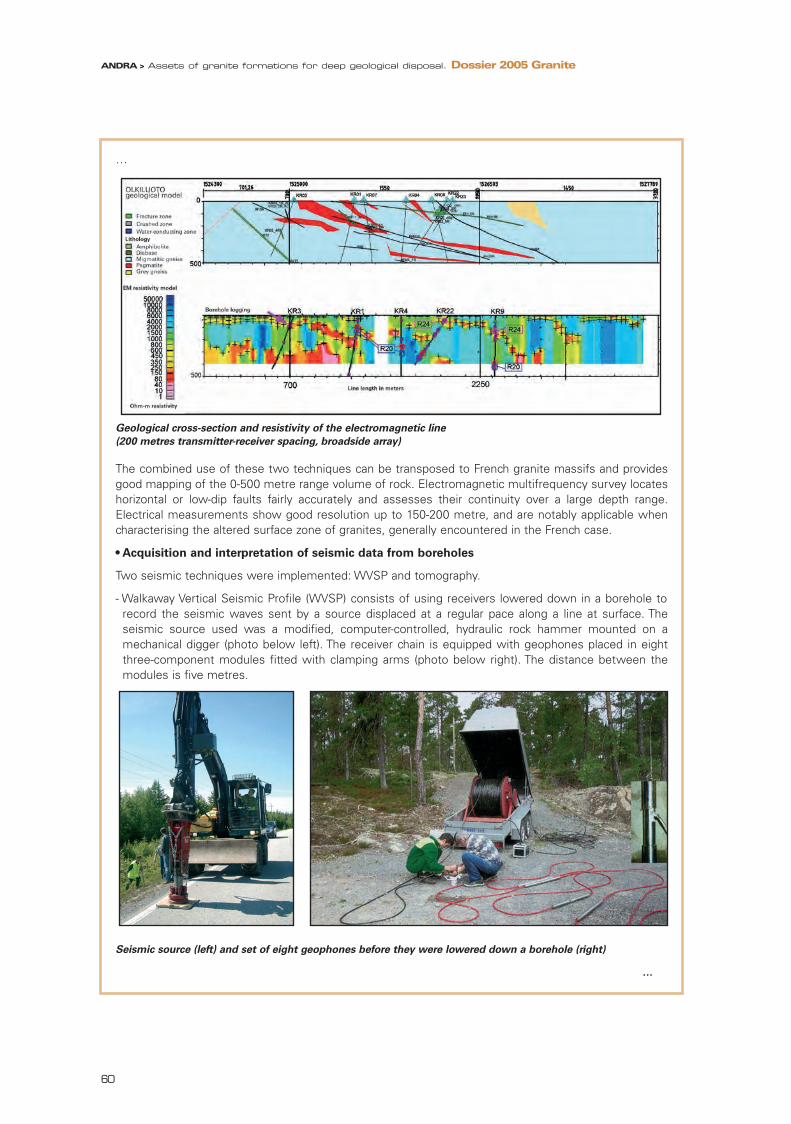
…
Geological cross-section and resistivity of the electromagnetic line
(200 metres transmitter-receiver spacing, broadside array)
The combined use of these two techniques can be transposed to French granite massifs and providesgood mapping of the 0-500 metre range volume of rock. Electromagnetic multifrequency survey locateshorizontal or low-dip faults fairly accurately and assesses their continuity over a large depth range.Electrical measurements show good resolution up to 150-200 metre, and are notably applicable whencharacterising the altered surface zone of granites, generally encountered in the French case.
• Acquisition and interpretation of seismic data from boreholes
Two seismic techniques were implemented: WVSP and tomography.
- Walkaway Vertical Seismic Profile (WVSP) consists of using receivers lowered down in a borehole torecord the seismic waves sent by a source displaced at a regular pace along a line at surface. Theseismic source used was a modified, computer-controlled, hydraulic rock hammer mounted on amechanical digger (photo below left). The receiver chain is equipped with geophones placed in eightthree-component modules fitted with clamping arms (photo below right). The distance between themodules is five metres.
Seismic source (left) and set of eight geophones before they were lowered down a borehole (right)
…
ANDRA > Assets of granite formations for deep geological disposal. Dossier 2005 Granite
60
95467_Chap3_Granit.qxd 11/04/07 14:12 Page 60

3
Understanding and modelling granite
…
The number and position of the receivers were determined to identify faults or contacts between rocksof a different kind at various depths. They were chosen according to the orientation and dip of thesegeological objects off which the seismic waves are reflected. A total of four boreholes were used in thisway and the sources were displaced along three lines.
Measurement processing and interpretation identified around twenty reflectors – mainly contactsbetween rocks of different kinds or fractures – which were then integrated into a consistent geologicalmodel (figure below). This technique, tested in Finland, is applicable to all granite environments.
Left, interpretation of the WVSP reflectors. Right, tomogram of seismic velocities between boreholes
KR04 and KR10
- Seismic tomography consists of recording, with receivers lowered into a borehole, the seismic wavessent by a source displaced at a regular pace in another nearby borehole. Measurements were takenbetween two deep boreholes at a distance ranging from approximately 250 metres near the surface to150 metres underground.
- The piezoelectric seismic source produces high-frequency signals with significant penetration in themedium, from tens to hundreds of metres. It was displaced every two metres. The receivers consistedof a chain of 30 piezoelectric sensors two metres apart. After processing the data, the seismic wavevelocity tomogram was compared with the borehole data to identify the continuity or discontinuity ofthe faults detected between boreholes (figure above).
- The tests showed that the technique can be used for borehole distances of up to some 250 metres,which would lead to optimise the number of boreholes to be drilled from underground structure.
ANDRA > Assets of granite formations for deep geological disposal. Dossier 2005 Granite
61
95467_Chap3_Granit.qxd 11/04/07 14:12 Page 61

2.3 Data integration and uncertainty processing
The main purpose of geological modelling is to produce 3D models of the granite structure, i.e. the distributionin the massif of the various geological objects composing either the rock itself or the fractures.
It also aims to identify and assess, throughout the exploratory stages, the uncertainties associated with themodels produced in order to reduce them and, ultimately, identify those that cannot be reduced so that theycan be taken into account in the safety analyses and repository design. For example, the complete, precisepattern of a fault is never totally accessible in 3D; therefore an input to repository design is the definition ofthe margins of confidence related to the modelling of such a structure (figure below).
Uncertainty regarding the fault line on the basis of borehole data:
a) from deep boreholes, b) from shallow boreholes
In this respect, consistency of the observations and the models produced on various scales is a key elementin the interpretation of field data and its integration into a 3D model.
Ultimately, the understanding of the geological objects forming the model, i.e. the consistency of theirintegration into the geological history of the granite, is indicative of the robustness of the model. It is foundedon both basic and specific studies often involving work beyond the perimeter of the concerned site.
2.3.1 The input of basic studiesUnderstanding the significance of the various rock units or fractures composing the geological model of agranite massif implies relocating them in the history of the granite from its genesis to the current period.
The questions most often examined concern the mineralogical and chemical composition of the rocksindicating the origin of the magmas. Interpretation requires age measurements or isotopic geochemicalanalyses, for example, to distinguish between magma families.
Analysis of the fractures and the various tectonic phases which gave rise to them is also an important area ofstudy in understanding the history of the granite. By understanding how the fractures formed and to whichepisodes in the history of the granite the minerals forming them relate, one can carry out extrapolation, at therelevant scale, from field data collected in observation points or particular measurements: rock outcrops on thesurface, boreholes and underground geological surveys.
ANDRA > Assets of granite formations for deep geological disposal. Dossier 2005 Granite
62
95467_Chap3_Granit.qxd 11/04/07 14:12 Page 62

3
Understanding and modelling granite
Understanding the clogging of fractures by minerals resulting from the ancient circulation of hydrothermalfluids is therefore a point which is systematically studied while exploring granite massifs. Evaluating the effectof the extent and chronology of this type of phenomena is important in appraising granite rock permeability.Through the results of the work on the hercynian granites of France (particularly, the work carried out by theFORPRO research group at the CNRS), were specified in more details the following points: the chronology and extentof the hydrothermal circulation phenomena observed in both the west of the Massif Central and the ArmoricanMassif, thus leading to the establishment of a general framework of this type of study for a particular site.
2.3.2 3D modelling and visualisation toolsProgress in computing has considerably increased the possibility of modelling and visualising, in 3D, thestructure of a geological formation, in particular granite and its major fracturing.
With the multiple angles of visualisation offered by computer tools, the consistency of geological andgeophysical surveys carried out in a complementary manner and on various scales can be verified much moreeasily.
3D modelling and visualisation tools
The data acquired over the course of the exploratory and characterisation stages is validated andintegrated into a database. This includes direct measurements and calculated data. It is generally locatedin 3D such as, for example, a sample of rock or fluid in a borehole, or a physical or geophysical in situmeasurement.
3D visualisation of the data is essential for the construction of geological models forming the backbone ofthe integrated models covering the various disciplines, first and foremost for the geometry of thestructures. Visualisation tools must be able to represent the various elements of the geological model, i.e.lithology and fractures. They must additionally manage the location and results of samples, boreholes andgeophysical measurements or interpretations. They must also integrate topography in the form of digitalterrain models, images or satellite or aerial photographs. Such tools provide user-friendly access to the 3Dmodels and enable them to be shared across various disciplines: geology, hydrogeology, geomechanics,geochemistry, etc.
Until quite recently, 3D visualisation was based on vertical cross-sections in two directions and plans atvarious depths. Today, computing provides interpolation and visualisation tools for the construction of truethree-dimensional models. The main difficulty consisted in linking database and 3D visualisation for thevarious types of geological formation encountered, especially for the granite medium by taking account offracturing on various scales.
SKB has developed a so-called RVS system (Rock Visualisation System) for the visualisation of particularfaults and cross sections. Posiva has an equivalent system which has been supplemented by a miningvisualisation tool for the structures observed in the Onkalo underground facility at Olkiluoto. In France,Andra has adopted visualisation tools from the oil industry for the representation of the Charroux-Civraygranite massif (Vienne).
Left: visualisation of faults and cross sections with the RVS developed by SKB (Sweden).
Right: visualisation of the limits of the granites forming the Charroux-Civray massif (France).
ANDRA > Assets of granite formations for deep geological disposal. Dossier 2005 Granite
63
95467_Chap3_Granit.qxd 11/04/07 14:12 Page 63

3 Hydrogeological andhydrogeochemicalmodelling andtransfer simulations
Hydrogeological models are the support for radionuclide transfer simulations for long-term safety assessments.They are used to evaluate the water flows liable to occur during repository excavation and operation.
Hydrogeochemical models complement the hydrogeological models for the understanding of current and pasthydrogeological flows in the granite substratum. They therefore provide support to the radionuclide transfersimulations.
3.1 Issues relating to the modelling of a fractured medium
Hydrogeological and transfer models for granite are complex. This complexity stems from the representationof a fractured medium and the consideration of large scales of time and space in the studies of a repository.While low in term of rate and slow in term of kinetics, the water flows to be considered are essentially linkedto fractures, whose distribution in the granite does not follow a single and simple law.
The methods used have undergone major developments in recent decades. The progress made in the oilindustry has in particular been behind the methods and tools which could be adapted to the granite mediumand the repository studies.
Around ten years ago, many radionuclide transfer simulations were performed on the basis of majorsimplifications of the fractured granite medium consisting of processing with the numerical codes of anequivalent porous medium. In this method of processing, the simulations take into account the largest faultsand the role of the small-sized faults is processed by the allocation of hydraulic parameters weighted to themass of granite.
With the progress achieved, fractures can be processed more explicitly in increasingly large volumes of rockand simplifications in the representation of the granite have been reduced. They are now regularly integratedinto the models and simulations performed on an international level, with the general simulation approachrelying on the complementarity of the two representations of granite: equivalent porous medium and mediumexplicitly represented with fracturing.
However, this does not clear up all the difficulties inherent in the models to be produced. The questions to beconsidered relate to the characterisation and the data to be gathered, and also to data processing and theproblem of digital simulation. Ultimately, it is a matter of controlling the simplifications which must beintroduced throughout the modelling process; in other words, understanding their full meaning, both in termsof the elementary phenomena considered and of their integration into the models and simulations.
ANDRA > Assets of granite formations for deep geological disposal. Dossier 2005 Granite
64
95467_Chap3_Granit.qxd 11/04/07 14:13 Page 64
3
Understanding and modelling granite
Hydrogeological models in a continuous porous medium and in fracture networks
Hydrogeological modelling of a fractured granite massif comes up against two major requirements formodelling:
- firstly, it must take into consideration a complex network of fractures, down to the smallest fracturesliable to be intercepted by a repository component, in order to appraise correctly the flows occurringthere,
- and secondly, it is essential to extend modelling over sufficiently large volumes to ensure that all factorsdetermining underground flows are taken into account: topography, hydrographic system often beyondthe limits of the granite massif, hydraulic characteristics of the altered superficial parts of the granitemassif, etc.
As it is not yet possible with current computing resources to use a fracture network model over thewhole of the considerable volume that would need to be discretised on the small fracture scale, thesolution involves the integration, on various scales, of “porous equivalent” models and modelsrepresenting explicitly the fracture networks.
• “Equivalent porous medium” models
In a continuous porous medium model, flows are assumed to use the whole volume of rock available andcomply macroscopically with Darcy’s law. Water flows depend directly on the permeability of themedium. This model, valid for porous media, can be used for fractured rocks over a certain volume whichdepends on the geometric and hydraulic characteristics of the fracture networks in question.
For example, the generic exercises “Everest” and “SPA” to simulate radionuclide transfer in a granitemedium were conducted, with the support of the European Union, on the basis of such assumptions.
On a regional scale, i.e. over areas exceeding a hundred square kilometres and terrain several kilometresthick (schematically 15kmx15kmx3000m), hydrogeological modelling is still based on suchsimplifications. Faults are taken into consideration in the model through the attribution of “equivalent”hydraulic properties to parts or the whole of the modelled volume.
• Models explicitly taking account of fractures
Several types of modelling can take a fracture network explicitly into account. Discrete fracture network(DFN) models, the most widely used, consider a medium in which, in steady state, only fractures play apart in the advective flow. The flow is thus restricted by the dimension of the fractures, especiallythickness and width. The geometry of each fracture is defined, enabling the hydraulic connectivity of thenetwork to be determined. Hydraulic transmissivity parameter is attributed to each fracture and then,hydraulic heads and flows can be calculated at any point of the network.
The field of application of DFN models is more specifically hydrogeological modelling and transfersimulations on the scale of a repository module (approximate volume: 500 m x 500 m x 300 m). WithDFN modelling, all fractures extending up to approximately 5 m can be integrated.
• Integration of models of various scales and various types
Modelling scales must fit consistently with the various types of models. With today’s computer tools,models performed at various scale can be integrated by successive iterations, and the consistency ofparameters used on various scales can be achieved from the regional scale to the repository module anddisposal cell scale.
ANDRA > Assets of granite formations for deep geological disposal. Dossier 2005 Granite
65
95467_Chap3_Granit.qxd 11/04/07 14:13 Page 65
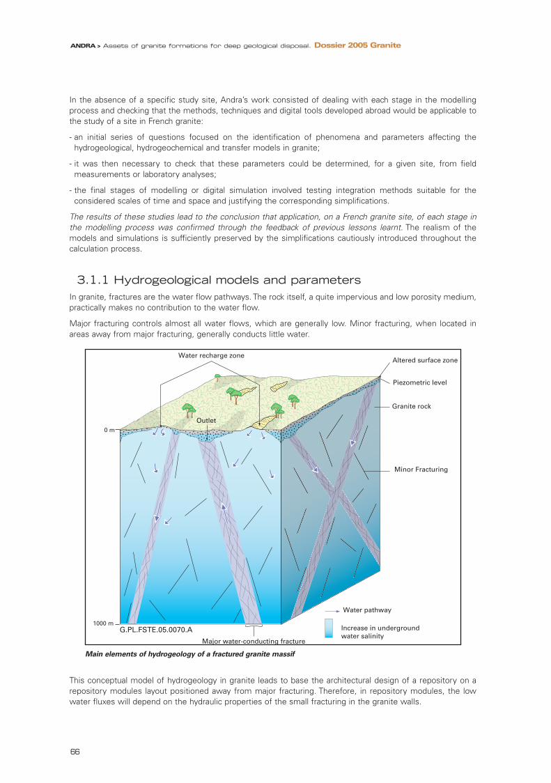
In the absence of a specific study site, Andra’s work consisted of dealing with each stage in the modellingprocess and checking that the methods, techniques and digital tools developed abroad would be applicable tothe study of a site in French granite:
- an initial series of questions focused on the identification of phenomena and parameters affecting thehydrogeological, hydrogeochemical and transfer models in granite;
- it was then necessary to check that these parameters could be determined, for a given site, from fieldmeasurements or laboratory analyses;
- the final stages of modelling or digital simulation involved testing integration methods suitable for theconsidered scales of time and space and justifying the corresponding simplifications.
The results of these studies lead to the conclusion that application, on a French granite site, of each stage inthe modelling process was confirmed through the feedback of previous lessons learnt. The realism of themodels and simulations is sufficiently preserved by the simplifications cautiously introduced throughout thecalculation process.
3.1.1 Hydrogeological models and parametersIn granite, fractures are the water flow pathways. The rock itself, a quite impervious and low porosity medium,practically makes no contribution to the water flow.
Major fracturing controls almost all water flows, which are generally low. Minor fracturing, when located inareas away from major fracturing, generally conducts little water.
Main elements of hydrogeology of a fractured granite massif
This conceptual model of hydrogeology in granite leads to base the architectural design of a repository on arepository modules layout positioned away from major fracturing. Therefore, in repository modules, the lowwater fluxes will depend on the hydraulic properties of the small fracturing in the granite walls.
0 m
1 0 0 0 m G.PL.FSTE.05.0070.A
Water recharge zone
Outlet
Altered surface zone
Piezometric level
Granite rock
Minor Fracturing
Water pathway
Increase in underground water salinity
Major water-conducting fracture
ANDRA > Assets of granite formations for deep geological disposal. Dossier 2005 Granite
66
95467_Chap3_Granit.qxd 11/04/07 14:13 Page 66

3
Understanding and modelling granite
Water flows in a repository depend on the orientation and value of hydraulic head gradient, driving force ofunderground flows. They depend, on the one hand, on the site topography and, on the other hand, on theproperties of granite massif surface parts, which control rainwater infiltration. Generally, gradients get weakerdeeper down which helps to limit water fluxes at repository level.
The hydrogeological modelling of a granite site is thus based on the fracture distribution, the hydraulicparameters of rock and fractures (fracture transmissivity and interconnectivity) and the values of the hydraulicgradients.
The groundwater chemical characteristics, especially salinity, can also affect hydrogeological and transportmodels. If the groundwater is very saline, its density may lead to a stratification of water versus depth. Thismay particularly concern coastal situations or ancient brine. Such situations are taken into account in the currentsite studies carried out in Sweden and Finland. This brings a feedback in this area.
3.1.2. Transfer and retention models in graniteMany radionuclides show little mobility in granite due to their low solubility under the chemical environmentconditions prevalent underground: reducing medium, pH remaining close to neutral, etc. This is particularly thecase with actinides. However, other more soluble radionuclides are mobile (iodine-129, chlorine-36 andcaesium-135 for example). Therefore, both conceptual models showing the transport and retention of radionu-clides in the granite rock and fractures, and parameter quantification elements to be introduced into the simula-tions, are needed. This important issue has formed the subject of a very active international cooperation,notably through experiments conducted at the Äspö laboratory in Sweden.
Various phenomena play a role in the transport and retention of radionuclides in a fractured graniteenvironment, the main ones being advection, dispersion and diffusion.
When water circulates in the open parts of fractures, radionuclides in solution also move as they are carried bywater. This is advective transport. The geometric complexity of the multiple pathways taken by the water flowsleads to the dispersion of solutes in the course of transport.
However, the kinetics of water flow are slow. The diffusion phenomenon is therefore superimposed overtransport by advection/dispersion. It concerns all moving elements, but also the numerous volumes still ormoving very slowly, contained in the intimate structure of the fractures (small diverticula, rock wall altered to agreater or lesser extent, possible porous filling, etc.). Diffusion encourages the adsorption (trapping) of theradionuclides liable to fix themselves to the fracture walls or to “brecciated” rock minerals and elements fillingthe fractures and multiplying the accessible surfaces. By enabling certain radionuclides to leave the circulatingwater flow for some time, the diffusion and retention phenomena delay solute migration compared withadvective transport.
This conceptual transport model (figure next page) has been enhanced through experiments carried out at theÄspö laboratory in Sweden. The experiments and associated modelling exercises confirmed the role ofdiffusion phenomena in the transfer of radionuclides in a fracture and identified the fracture componentsinvolved in transport, especially the role of stagnant zones where diffusion between fractures and the wall rockis high.
The transport parameters to be characterised are therefore essentially the coefficients of diffusion into the rockand the retention parameters of the rock and fracture minerals.
ANDRA > Assets of granite formations for deep geological disposal. Dossier 2005 Granite
67
95467_Chap3_Granit.qxd 11/04/07 14:13 Page 67

Conceptual model of fractures and transport phenomena
3.2 Data collectionBoreholes are the most commonly used means for underground hydrogeological or hydrogeochemical surveyand characterisation work in a granite massif. At each stage in the exploratory process, from the surface orunderground, the borehole techniques – coring or drilling – are adapted to the aims of hydrogeological orhydrogeochemical characterisation. There is a considerable amount of feedback in this area providing a verycomprehensive range of tested techniques and tools suited to numerous contexts.
3.2.1 Hydrogeological dataThe hydraulic conductivity of granite or, to be more precise, that of the fractures producing conductivity, isessentially determined by hydraulic tests in boreholes.
Various techniques are used depending on the extent of the hydraulic transmissivity of the fractures:
- for large fractures where transmissivity is significant, conventional hydrogeological techniques (pumping,current flow-meter logging, etc.) are adapted to determine the hydraulic characteristics of the granite;
- if transmissivity is lower, the “fluid logging” technique based on the detection of differences in electricalconductivity, and therefore salinity, is quite suited to locating low flow-rate fractures;
- if transmissivity is very low (as in the case of small fractures), the fluid logging technique is combined withdifferential flow logging in the borehole similar to the technique developed in Finland and used systematicallyin exploratory boreholes;
- finally, tests between fixed packers can be used for accurate characterisation of the granite rock, very lowpermeability rock by nature, and small fractures where transmissivity is very low.
Fracture interconnectivity is another important parameter. It can be assessed by testing hydraulic interferencebetween boreholes. This type of test particularly concerns large fractures (figure hereafter).
Other measurements can be carried out using equipment measuring the water pressure at several levels
G.PL.FSTE.05.0019.A
Altered granite wall
Fault clay
Dead-end micro-fracturing
Wall crystallisations
Open zone of fracture
Deformed/crushed granite rock
Tra
nsp
ort
by
adve
ctio
n/d
isp
ersi
on
in
th
e o
pen
fra
ctu
re
Mig
rati
on
by
dif
fusi
on
ANDRA > Assets of granite formations for deep geological disposal. Dossier 2005 Granite
68
95467_Chap3_Granit.qxd 11/04/07 14:13 Page 68

3
Understanding and modelling granite
within the same borehole, through various measurement chambers positioned in between packers. With thistechnique, the water pressure of a specific fracture or fracture zone can be measured and the connectivitybetween fractures or groups of fractures can be evaluated.
The developments in these techniques, especially for oil exploration purposes, provide a complementary setof tools able to characterise the connectivity of a network of fractures on various scales: from tens to severalhundred metres.
A third set of information concerns hydraulic head gradients, driving force of flows in a massif. The gradientsare established on the basis of topographical data and piezometric measurements in boreholes.
Left, schematic diagram of a hydraulic interference test
designed to study fracture connectivity between two boreholes (SKB data).
Right, continuous measurements in boreholes showing the relationship between flow rate and electrical conductivity
to determine the precise position of water conducting fractures (Posiva data).
3.2.2 Hydrochemical dataThe composition of the water in a granite massif is determined from water samples taken from the boreholes.
Various techniques have gradually been developed to meet the requirements of the planned chemical orisotopic analyses. Depending on the water production detected by hydrogeological measurements, fluidsamples can be taken directly from the water produced at the wellhead, or downhole using sealed bottles orcontinuous sampling techniques.
ANDRA > Assets of granite formations for deep geological disposal. Dossier 2005 Granite
69
95467_Chap3_Granit.qxd 11/04/07 14:13 Page 69

PAVE borehole fluid sampling system developed in Finland (Posiva data)
3.2.3 Transfer and retention parameters The diffusion properties of the granite rock are established during exploratory work on a granite massif bysamples taken from cored boreholes and underground drifts, as well as from surface outcrops if suitable withrespect to alteration conditions.
Retention properties are linked to the mineralogical characterisation of the rock and fractures as well as to theintimate geometry of the voids and porous volumes. The values of the associated parameters are establishedfrom measurements on granite samples. Tracer tests between boreholes are conducted in situ to verify theconsistency of measurements on the samples with extrapolated values, in relation with geological variability,on the scale of a large fracture.
• Analyses and measurements on granite samples
The diffusion coefficients of granite have been measured on several types of granite in France and abroad. Theyare generally performed by testing the diffusion kinetics of tritiated water through a few centimetre thick sliceof granite. This method was used in the course of the works carried out by Andra from 1994 to 1996 on theCharroux-Civray granite massif.
As this massif is composed of several types of granite, extensive sampling of various types of rock waspossible. The diffusion coefficients measured were generally very low with values most often below 10-13m2/s.When the granite massif was subjected to major hydrothermal alterations during its geological history, thevalues could increase by a factor of 10 or 100.
• Tracer tests between boreholes
In granite, tracer tests consist of injecting a cocktail of tracers at a precise point of a fracture and observing itsrelease, at a certain distance, in the same fracture or in another connected fracture. Providing that a sufficientlyaccurate geological and hydraulic characterisation of the fracture network has been completed beforehand, thistype of test can be used to assess the delay on radionuclide transfer compared with water circulation.
ANDRA > Assets of granite formations for deep geological disposal. Dossier 2005 Granite
70
95467_Chap3_Granit.qxd 11/04/07 14:13 Page 70

3
Understanding and modelling granite
A major experimental programme was conducted on such tracer techniques at the Äspö laboratory in Sweden(“TRUE” experiment). They led to the development of a conceptual transport model in a fractured medium andthe quantification of differential delays between radionuclides. A delay factor of 250 was thereby detected onthe same pathway in a single fracture for caesium compared with an undelayed element (bromine for example).
Comparative release curve of various tracers on a same pathway
3.3 Integration methods providing the link between site exploration and safety analyses
Methods are available today to integrate site exploration data into safety analyses and design studies. They arebased on a complete modelling process from acquisition of geological data to simulation of radionuclidetransfer, and on the full range of scientific knowledge contributing to an understanding of granite massif hydrogeology. Among these data, hydrogeochemistry forms a natural complement to hydrogeological modelsin understanding water flows in granite and its environment.
3.3.1 A modelling process which explicitly includes granite fracturing data
Questions relating to the integration of site data into safety assessments, through hydrogeological modellingand radionuclide transfer simulations, concern the following main aspects:
- integration of the various scales of space into the geological and hydrogeological models;
- inclusion of the variability in the fracture transport properties within a granite massif;
- inclusion of the various phenomena involved in radionuclide transfer and retention in a granite massif fracturenetwork;
- integration of the various phenomena over large time scales.
These issues have been covered in numerous studies and applications, especially in the framework of the“Äspö Task Force” project, carried out in the context of an international cooperation agreement and based on
ANDRA > Assets of granite formations for deep geological disposal. Dossier 2005 Granite
71
95467_Chap3_Granit.qxd 11/04/07 14:13 Page 71

the Swedish laboratory data. The various methods studied answer the questions raised and integrate site datainto the various scales of time and space to be considered in the models. The methods are based on the explicitinclusion of granite fracturing data collected at a site. Due to the development of methods of modelling agranite medium as “fracture networks”, site data can indeed be introduced into the modelling process withoutdrastic simplification from the earliest stages of simulation. The simplifications form part of a gradual, iterativeprocess designed to compare site data and modelling results throughout the stages of the site surveying.
Modelling process and site data
In a generic study context, Andra has carried out modelling exercises supported by knowledge acquiredin the international framework and field data collected in France, especially at the Vienne site (1994-1996)studied by Andra or the Auriat site (Creuse) studied by the CEA (1980-1981). This has resulted in a typicaloutline of the modelling process to be adopted throughout the various exploratory stages of a site.
On both regional and massif scales, geological models represent the structure of a granite massif in itsgeological context. The models identify the various lithological units composing a granite massif and itssurrounding formations. Major fracturing – regional or “local” faults – modelled by a deterministicapproach, i.e. by establishing 3D geometry on the basis of geological surface mapping, geophysicalsurveys and boreholes drilled during exploratory work. Hydrogeological models in a “continuous porousmedium” are established by integrating hydrogeological measurements from boreholes (pressuremeasurement, permeability, etc.).
Example of a 3D model showing the distribution of permeability and its evolution with depth
On the scale of the repository module, geological models include small fractures, characterised eitherfrom surface surveys or by underground structures. The geometry and distribution of these smallfractures in a granite massif are processed in a probabilistic manner on the basis of site data. Processinggroups the fractures into “families of fractures” with specific geological, hydrogeological and transportproperties. Distribution laws, validated by inversion methods and by comparison with site data, deal withvariability in the properties of fractures in granite on the scale of one or more repository modules in aprobabilistic manner. …
ANDRA > Assets of granite formations for deep geological disposal. Dossier 2005 Granite
72
95467_Chap3_Granit.qxd 11/04/07 14:13 Page 72

3
Understanding and modelling granite
3.3.2 The input of hydrogeochemistryThe composition of granite water reflects the chemical exchanges between the water, the granite rocks andfractures, and therefore the water circulations within the granite. Understanding and modelling theseexchanges is a way of reconstructing their pathways.
The increase in water salinity with depth, often observed in granite environments, reflects the exchangesbetween deep, more ancient, water of a granite massif and the more recent shallower water. Isotopicevolutions in the composition of the water show the same tendency. This was observed at the Vienne sitestudied by Andra in France.
Successfully developed in Fenno-Scandinavia and Canada, methods of modelling exchanges between watersof different origins have made it possible to reconstruct the evolution in the chemical composition of granitewater and its present distribution in a massif. Applicable in the French context, these methods provideelements required to validate hydrogeological and transport models to be produced on a site scale and overlong periods.
…
Fracture network on a module scale; intersections of fractures with a horizontal plane are classified by transmissivity
The various methods of integration guarantee continuity and provide a link for models on both regionaland repository module scales. From a hydrogeological viewpoint, water flow balance and continuity inthe distribution of hydraulic head gradients between the various modelling scales are the main elementsensuring that the various modelling scales are consistent with each other.
ANDRA > Assets of granite formations for deep geological disposal. Dossier 2005 Granite
73
95467_Chap3_Granit.qxd 11/04/07 14:13 Page 73

Hydrogeochemical modelling of a granite site: the example of Äspö in Sweden
The geological and hydrogeological history of the Äspö region is dominated by quaternary glacialepisodes which have controlled the paleogeography of the site with the presence, then the melting, ofan icecap. There has been a succession of coastal sea and lake situations. The water circulating under-ground in the granite is therefore the result of a mixture of seawater, brackish water, water from meltingice and recent rainwater (figure below).
Postglaciation conceptual scenario of the evolution of the Äspö site (SKB data)
From the hydrogeochemical modelling methods developed from this paleogeographic outline, theevolution in the composition of waters of various origins and their current distribution in the granitemassif was reconstructed. Model accuracy limited by the existence of a minimum proportion of 10% ofa water of a given origin. The hydrogeochemical model therefore complements the hydrogeologicalmodels; it is notably used to validate the hydraulic properties of the granite on a site scale andhydrogeological models over large time scales
ANDRA > Assets of granite formations for deep geological disposal. Dossier 2005 Granite
74
G.PL.FSTE.05.0120.0
> BP 13 000
> BP 10 300 - 9 500
> BP 8 000 - 2 000
> BP 9 500 - 8 000
> BP 13 000 - 10 300
Present day
Frozen Baltic lake
Frozen Baltic lake
Yoldia sea
Littorina sea
Ancylus lake
Baltic sea
Ice Fresh water Brackish water Salty water
95467_Chap3_Granit.qxd 11/04/07 14:13 Page 74

3
Understanding and modelling granite
4Geomechanicalmodelling
The considerable feedback relating to underground excavations in granite shows the feasibility of large andstable deep structures.
However, the construction of stable structures does not automatically mean the absence of any damage to thegranite walls due to their excavation. Neither does it explain how would be the mechanical behaviour of thegranite in the environment of a repository in response notably to thermal stress.
Understanding and modelling granite therefore also consists of providing an adequate description of themechanical behaviour of the granite and its possible damage during the various phases of the disposal process.The consequences of this behaviour on the hydraulic properties of the massif and radionuclide transfer mustalso be assessed.
Therefore are needed:
- methods to characterise the granite massif studied from a mechanical point of view;
- digital simulation tools for the behaviour of the granite (fractured medium) in a repository.
4.1 Mechanical characteristics of the granite and data collection on site
The mechanical characterisation of a granite massif traditionally comprises two parts:
- characterisation of the mechanical properties of the rock, including the fracturing that may affect it;
- measurement of the natural mechanical constraints prevalent at depth.
4.1.1 Mechanical characteristics of granite rock Granite is a mechanically resistant rock10, the mechanical behaviour of which essentially results from the massiffracturing.
Repository structures are to be located in rock with little fracturing; however, fracturing is characterised toensure that it is not liable to weaken the rock around the structures. It depends on the “surface roughness” ofthe fracture and the nature of its minerals. Fracture strength is assessed by shear tests according to currentexperimental methods.
The numerous tests performed on samples on an international framework have provided a basis for thedevelopment of laws relating to the mechanical behaviour of the fractures according to their geometric andmineralogical characteristics. Full-scale in situ experiments are used to adjust the various coefficients used inthe models on the scale of the studied structures. These were notably performed in the Swedish and Canadianunderground laboratories.
ANDRA > Assets of granite formations for deep geological disposal. Dossier 2005 Granite
75
[10] Granite compressive strength is over 100 MPa; its tensile strength is over 6 Mpa.
95467_Chap3_Granit.qxd 11/04/07 14:13 Page 75

Equipment used for shear tests on fracture samples in granite and photos of post-shear fractures surfaces (5 min)
(Riss and al, 1997)
4.1.2 Natural underground stress in a granite massifThe mechanical stress state prevalent in an underground granite massif results from the weight of the overlyingterrain and the geodynamic stress. The sizing of a structure depends on the anisotropy of horizontal or vertical stresses underground. High stressanisotropy has, for example, been observed underground at the Lac du Bonnet laboratory in Canada. Thiscorresponds to a quite specific situation: at this point, the granite massif below 300 m is not fractured and thetectonic stresses to which it has been subjected over its history could not have been released. The behaviourof drifts under such a configuration has been tested and their geometry adjusted. Mechanical modelsrepresenting the behaviour of granite rupture under such conditions have been finalised.
Lac du Bonnet underground laboratory in Canada: damage to the granite wall of a circular drift subjected
to a highly anisotropic stress configuration
In the French tectonic context, the ratio between major horizontal stress and vertical stress is estimated at avalue between 1 and 2. It shows a low anisotropy of underground stress and the construction of undergroundstructures should be rather straightforward. This appraisal cannot be generalised, however, and must bevalidated by in situ stress measurements for each site.
Stress measurement techniques have progressed considerably in recent decades. These techniques includehydraulic fracturing tests performed in boreholes and adapted to granite which provide comparable values fromone point to another of the massif. These tests consist of causing fractures to open in the rock through theinjection of water under pressure. Open fractures are identified and characterised and, as a result, the orientation
ANDRA > Assets of granite formations for deep geological disposal. Dossier 2005 Granite
76
95467_Chap3_Granit.qxd 11/04/07 14:13 Page 76
3
Understanding and modelling granite
and value of the stresses are known. This type of test has been conducted in France and abroad; it enabled todevelop measurement techniques and identify uncertainties linked to the inclusion of fractures initially existingin the rock in the processing and interpretation of the data.
4.2 Simulation of the mechanical behaviour of granite
Simulation of the mechanical behaviour of a fractured granite massif, under mechanical or thermal stress, callson specific models focusing both on the behaviour of the rock matrix (continuous medium) and on thebehaviour of the fractures as discrete elements. Development and validation work is still ongoing to determineeffective solutions covering all aspects of behaviour of the rock massif.
The questions to be resolved stem firstly from the various scales and families of fracturing to be taken intoconsideration and, secondly, from the complex relationships between mechanical deformations of the fracturesand changes to their hydraulic properties.
Thus, simulations are most often used to verify that the fields of deformation studied are of low amplitude, withno consequence at first sight on the mechanical, hydraulic and thermal properties of the massif.
For the design, dimensions are determined with safety margins and ensure that phenomena remain within thescope of the minor deformation field. The arrangements proposed for a repository in terms of the backfill, sealor swelling clay buffer are also means of limiting deformations in structures subjected to mechanical andthermal stress.
4.2.1 Modelling of mechanical damage to the granite walls of the structures
Stress concentrations may locally appear in the walls of the structures during excavation and cause damage tothe rock and spontaneous flaking. Experiments conducted in underground laboratories have pinpointed theconditions under which such damage can occur, and tested the various digital models developed.
The models developed have provided the criteria with respect to occurrence of such phenomena; for example,relationships between the tangential stresses affecting the rock walls of the structures and the resistance ofthe rock measured by a uniaxial compression test. The various models, implemented on the basis a discretefracture model or representing the granite in the form of grains (“particles”), are consistent and have led to theidentification of uncertainties to be considered in structure design and safety analyse.
Experiments conducted at laboratories in Canada (“Room 209” and “Mine by experiment”), Sweden (“ZEDEX”),Finland (“Olkiluoto Research Tunnel”) and Japan (“Kamaishi mine”) have examined the creation of a damagedzone in the rock according to various methods of excavation (drill and blast, small diameter tunnel boringmachine, etc.). They show that damage remains very limited (extending to less than one metre) in all cases andthat it is possible to minimise it considerably by using boring methods (then a few centimetres extension).
Similarly, boring the granite for waste disposal vertical boreholes significantly reduces damage to the walls ofthe disposal structures. A highly detailed analysis of damage to the granite wall of drilled boreholes, carried outin the Olkiluoto research tunnel (Finland), has shown that damage is very minor and is reduced todestructuration of granite grains to a depth of one centimetre or less.
ANDRA > Assets of granite formations for deep geological disposal. Dossier 2005 Granite
77
95467_Chap3_Granit.qxd 11/04/07 14:13 Page 77

Damaged zone on the drift wall (“ZEDEX” experiment at the Äspö laboratory)
4.2.2 Coupled hydromechanical and thermo-hydromechanical models
The hydraulic properties of fractures, notably small fractures, depend on the stress state of the massif. Thehydraulic transmissivity of the fractures is sensitive to normal stress exerted on the fracture planes. Local modifi-cation of the stress system applied here is therefore liable to change the hydraulic properties. This may be due tostructure excavation or to the heating of the massif linked to the disposal of exothermic waste.
The simulation of the modifications to the hydraulic properties of a fracture network is complex both from atheoretical point of view and in terms of experimental validation. However, the various experiments conducted inFrance and abroad have identified the important parameters to be integrated into the simulations: geometry andmechanical properties of the fractures linked to the roughness of the fracture planes, the nature of the fillingminerals at their hydraulic or mechanical openings, etc. Various behaviour laws have been proposed and digitalmodels established.
International exercises carried out on this theme, such as the Decovalex or Benchpar projects which are notablybased on the results of experiments in the Kamaishi mine in Japan, have concluded that mechanical models canprovide the order of magnitude of the changes to the stress state and movements along the fractures of fracturedgranite. This defines the deformation system and field to be integrated into both the safety analyse and the designof repository architectures.
In particular, emplacing backfill and swelling clay buffers is an arrangement generally adopted for the disposal ofspent fuel and exothermic C waste. Swelling clays contribute to the stability of the walls of the structures whereheat-related stress impact is the largest.
ANDRA > Assets of granite formations for deep geological disposal. Dossier 2005 Granite
78
95467_Chap3_Granit.qxd 11/04/07 14:13 Page 78

3
Understanding and modelling granite
5Considering very long-termgeodynamic evolutionand climate change: geoprospective study
On the scale of several hundred thousand years, a granite massif and its environment are liable to undergochanges linked to internal (tectonic movements, earthquakes and volcanism) or external geodynamicphenomena (climate changes and surface erosion phenomena). The purpose of the studies is therefore toidentify the phenomena that may be involved in the various timescales to be considered in the evolution of arepository.
Since there is no particular study site, this work had two objectives:
- to identify the factors of geodynamic evolution to be considered in site exploration in order to comply withthe recommendations of RFS III.2.f. in terms of long-term stability;
- to assess the possible consequences of the evolution of a granite site on the environment of a repository,especially from a hydrogeological point of view.
The analysis was conducted generically on the scale of mainland France, with a focus on the granite regions ofthe Massif Central and the Armorican Massif. From a methodological point of view, the evolution of theseregions over hundreds of thousand years in the future is assessed on the basis of the geological history of thelast ten million years. This period includes the quaternary period (two million years) characterised by theinstallation of the current climate system.
5.1. Internal geodynamic phenomenaIn terms of internal geodynamics and plate tectonics, the granite regions of the Massif Central and theArmorican Massif are situated away from active zones. They are therefore characterised by deformations ofvery low amplitude, even on the scale of several hundred thousand years. Vertical ground movements are veryweak and seismic activity is minor.
Plate tectonics: France outside major deformation zones
The lithosphere, the solid, outer layer of the earth, is divided into a few vast domains (“plates”), theinternal deformation of which can be considered negligible on this scale, separated by narrow zoneswhere deformations are concentrated. These lithospheric plates move in relation to each other.
On this scale, France belongs to the Eurasian plate, bordered by the African plate to the south and theAtlantic opening to the west. On the scale of plate tectonics, deformations are concentrated in Alpineand Mediterranean zones bordering the African plate, as illustrated by the distribution of strong earth-quakes recorded there. The granite areas of the Massif Central and the Armorican Massif are locatedaway from these areas of major deformation and are therefore protected from significant tectonicmovements on a scale of several hundred thousand years.
ANDRA > Assets of granite formations for deep geological disposal. Dossier 2005 Granite
79
95467_Chap3_Granit.qxd 11/04/07 14:13 Page 79

5.1.1. SeismicityA geodynamic context showing very little activity does not equate with the total absence of any seismicmanifestation, in other words earthquakes.
Numerous studies have been devoted to the assessment of the “seismic hazard” in France and have notablyled to the seismotectonic zoning of the country. For disposal studies, the assessment of the seismic hazardpools together the data recorded regularly over decades (“instrumental seismicity”), the results of researchover the historical periods (“historical seismicity”) and the paleoseismic field studies aimed at detecting thetrace of strong earthquakes from ancient times (thousands to hundreds of thousand years) in order to evaluatethe intensity and possible recurrence. In this evaluation, the granite massifs of the Massif Central and theArmorican Massif are located in zones of low or moderate seismicity. In such a context, the seismic hazard isnot a repository dimensioning factor. Indeed, it is often observed that earthquake impact is less pronouncedunderground than on the surface. The “free” surface of the earth is totally exposed to the effects of the seismicwaves originating underground, whereas the length and frequency of the seismic waves are such that theycannot generally produce significant movements in the underground rock or structures.
The long-term evolution of seismicity is in relation with the kinetics of plate tectonics. With no foreseeablechange on the scale of several hundred thousand years, no significant evolution in the seismicity level is to beconsidered for the future.
5.1.2. VolcanismVolcanic formations exist in the central and eastern parts of the Massif Central. Geologically, volcanic activityreached a peak some 20 million years ago. Volcanism was still active locally in the quaternary period (2 million years).
If the actual cause of this volcanism is debated within the scientific community, it appears that the eruptionpoints remain confined to precisely identified regions: the Chaîne des Puys, Ardèche volcanism for thegeologically most recent events (less than 100000 years ago). Bearing in mind the very slow dynamics of thesemechanisms, the creation of new volcanic regions on the scale of the next million years can be considered asquite inconceivable.
5.1.3. No notable evolution foreseeable on the scale of severalhundred thousand years
All in all, the slow geodynamic evolution of the granite regions considered in the French geological contextmeans that the consequences on a granite site are limited.
For all the granite massifs, no evolution is foreseeable on a ten thousand year-scale which meets the RFS III.2.frequirement which recommends that “for a period which must be equal to at least 10000 years, the stability[of the site] (which includes a limited and foreseeable evolution) must be demonstrated”.
On the scale of a hundred or several hundred thousand years, the geodynamic context of the consideredregions (Massif Central and Armorican Massif) indicates that a very slight evolution in a granite site isforeseeable for the majority of the granite massifs: indeed, underground stress changes are too slight to causeany changes to the hydraulic properties of the faults and fractures. In the case of a few granite massifs,particular situations linked to the proximity of major seismic faults (such as along the South Armorican shearzone) or volcanic activity (Massif Central), may require specific examinations.
Beyond the period of a few hundred thousand years, the consideration of the geodynamic evolution cannotsimply be based on general factors. It must be specifically studied for each considered massif. However, arepository site located away from the major regional accidents or a few zones of potential volcanic activity (andthereby complying with the recommendations of RFS III.2.f), would most probably be subjected to slight localmodifications on the timescales considered.
ANDRA > Assets of granite formations for deep geological disposal. Dossier 2005 Granite
80
95467_Chap3_Granit.qxd 11/04/07 14:13 Page 80

3
Understanding and modelling granite
5.2 External geodynamic phenomena:erosion and climate change
Erosion is, in the long term, the main factor liable to alter the environmental conditions of a repository site. This erosion is primarily caused by the hydrographic network: rivers, streams, etc. It is the result of both groundmovements and climate change.
Assessments made in various regions have led to generally similar estimates of the order of 5 to 20 metresmaximum per 100000 years for river valleys incision. Erosion rates on plateaux are much lower. These erosionphenomena, especially valley carving, are liable to change underground hydrogeological gradients and thepathways of the hydrogeological flows toward modified surface outlets. In connection with the recurrence ofglacial climates, the formation of permafrost on the upper and surface layers of the granite massif can alsotemporarily modify water infiltrations and their migration within the massif.
Limited consequences for a deep geological repository
Generally, the changes foreseeable on a scale of ten thousand years are very slight for all granite massifs inFrance, with no significant impact for a deep geological repository.
On a scale of a hundred or several hundred thousand years, foreseeable climate change may, at certain sites,modify the water infiltration fluxes into the massif and the hydraulic gradients. This would notably be the caseof coastal sites liable to be affected from a hydrogeological point of view by the retreat of the sea in glacialperiods. It may also be the case of some Massif Central sites with rather deep permafrost (200 to 300 metres).
Beyond a period of a few hundred thousand years, the changes to be taken into consideration and theircorresponding uncertainties may be greater, especially with regard to flow pathways between undergroundand surface. They concern particular situations such as that of the granite massifs of the Massif Central whichdrain towards the Mediterranean and which are liable to be affected, in the very long term, by more intenseerosion phenomena than those draining toward the Atlantic side. Such situations should be examined on aspecific basis to check whether foreseeable evolutions are likely to put at stake the environmental conditionsfavourable to a deep geological repository.
Climate change
Climate change is a natural component of the earth’s evolution. For almost 2 million years, glacial andinterglacial periods have alternated at the latitudes of the French territory. The last glacial episode reachedits peak 18000 years ago. The astronomic climate theory links climate change to oscillations in the earth’s movement around thesun. As a result, future climate change can be forecast with a return to new glacial cycles expected on ascale of around one hundred thousand years. It is also possible to appraise the possible consequencesof human activity (“greenhouse effect”) which would tend to delay this glacial recurrence.
ANDRA > Assets of granite formations for deep geological disposal. Dossier 2005 Granite
81
95467_Chap3_Granit.qxd 11/04/07 14:13 Page 81

82
ANDRA > Assets of granite formations for deep geological disposal. Dossier 2005 Granite
95467_Chap4_Granit.qxd 11/04/07 14:34 Page 82

83
4
Description ofrepository design in a granite medium p.84 > 1. The general architecture of a repository
p.90 > 2. The B & C waste and spent fuel disposal concepts
p.101 > 3. The reversible operation of the repository
ANDRA > Assets of granite formations for deep geological disposal. Dossier 2005 Granite
95467_Chap4_Granit.qxd 11/04/07 14:34 Page 83

The principles behind the design of a repository in a granite medium have been described in chapter 2: an architecture that takes advantage of the favourable properties of granite, engineered structures withcomplementary and redundant functions to those of the geological barrier, a dimensioning that limits thedisturbance of the granite medium and that takes into account the variability of the characteristics of Frenchgranites.
This chapter presents a description of the repository concepts as proposed by Andra. Since this study wascarried out in a generic framework, it cannot provide a precise description of the architectures that could bedefined only for any given site. These selected concepts are possible solutions which feasibility is confirmed intechnological terms. These reference concepts take also into account the phenomenological and safetyanalyses that have been conducted sufficiently systematically to ensure that all of the issues, relating to thedesign of a repository in a granite medium, have been examined.
The principles of the general architecture of a repository are described, particularly the arrangements thatwould allow it to be adapted to the geological configurations likely to be encountered in the French context.
The technical options adopted for the disposal of each of the categories of waste are then described, togetherwith the components of the various repository zones used as a reference in the studies (package, cell andrepository module).
In the last part, issues relating to the reversible operation of a repository in a granite medium are examined. Asa preliminary approach and at this stage of the project, it was checked that the feasibility of the various plannedoperations complying with the reversibility rationale of the disposal management cannot be ruled out.
1The generalarchitecture of a repository
As a general rule, a repository includes surface installations, structures providing access from the surface tothe various underground installations: connecting and reconnaissance drifts, shared infrastructures andrepository modules.
1.1 Surface installationsThe surface installations include the buildings for primary packages reception, the workshops for preparing therepository packages and the buffer storage facilities for controlling the throughput rates of industrial processes.The installations also include standard industrial equipment used for building and operating the repository'sunderground installations. In particular, the broken rock derived from excavating the underground installationsis stored on a dump and will then be partly used as backfill material.
1.2 A general architecture for undergroundinstallations adapted to the granite structure
In terms of long-term safety, the architecture of the underground installations is mainly designed to takeadvantage of the favourable properties of granite, especially its mechanical strength and its low permeability inthe "blocks" where it is not or only slightly fractured.
To ensure that these architectural arrangements are effective, even in case of partial failure, the structures arebackfilled and sealed by devices that fulfil complementary and redundant functions with those of granite.
The proposed architectural arrangements also aim at reducing the disturbance to the properties of the granitemedium, which could affect its confinement performance.
84
ANDRA > Assets of granite formations for deep geological disposal. Dossier 2005 Granite
95467_Chap4_Granit.qxd 11/04/07 14:34 Page 84

4
Description of repository design in a granite medium
85
The structures connecting the surface to the underground installations (shafts or ramps) or between repositorymodules (connecting drifts) provides the transfer of the various material throughputs: those related to works(rock excavation and building materials), the ventilation air and the waste packages to be emplaced. Thedistribution and the number of connecting drifts are determined to ensure a fully safe co-activity of bothconstruction works and (nuclear) operation in the repository. By principle, simultaneous construction andoperation activities in the same drift are ruled out.
The proposed architectural arrangements ensure the reversibility of the repository's operation, i.e. the possi-bility of retrieving waste packages, acting on the repository management process and being able to changeinstallation design.
1.2.1 The general architectural arrangements In their principles, the architectural arrangements studied can be applied to all French granites. However, on agiven site, it may be necessary to define architecture and dimensioning that take into account the specificcharacteristics of the considered granite formation.
• A modular architecture adapted to the fracturing of granite
The general architecture of the underground installations is adapted to the structure of the surrounding granite.The repository modules are installed in "blocks" of granite located apart from water conducting fractures. A buffer zone of undisturbed rock of several tens of metres (depending on the local characteristics of thegranite) is kept between modules and fractures. The distances between modules are generally of the order ofhundred metres. The general architecture of a repository depends on the distribution of "blocks" in the granitemassif hosting the repository.
The repository zones which include the repository modules for the same category of waste (B, C), or spent fuelif the need arises, are distinct.
To prevent interactions, especially chemical interactions, between waste packages of different types, eachrepository module will only include waste of the same type. For example, the B waste containing organicmatter is disposed of in dedicated modules.
The modular principle of the repository architecture has been adopted in a similar way at international level bythe various organisations conducting studies on the granite medium: Sweden (SKB), Finland (Posiva), Canada(AECL), Spain (Enresa), etc.
Modular architecture of the repository studied by SKB (Sweden)
ANDRA > Assets of granite formations for deep geological disposal. Dossier 2005 Granite
95467_Chap4_Granit.qxd 11/04/07 14:34 Page 85

Generally speaking, a modular architectural design of the repository, through its compartmentalisation,increases the safety by reducing the consequences of any possible failures at the module level. It is also animportant factor for reversible management, because it provides the possibility of a phased approach for thegeological survey, building and closure operations of the repository.
• The possibility of multi-level architecture
A granite formation generally provides a vast volume of rock with a depth of between 300 and 1000 metres,for a geological repository. This means flexibility to adapt the architecture to granite fracturing. Architectures onseveral levels are therefore possible, as studied in Sweden for the theoretical "Aberg" site, which was modelledon the basis of the Aspö underground laboratory data.
The analysis of the advantages and constraints of two-level architecture has underlined its interest: a distanceof about 100 metres between each level would prevent thermal interactions between the C waste or spent fuelrepository modules and would ensure the compliance with the maximum temperature criteria in the disposalcells.
• Structures connecting the surface and underground facilities (shafts or ramps) installed in relation to
the local hydrogeological context
Shafts or ramps could be envisaged to connect the surface to the underground installations. They are generallydesigned as a complementary feature in the repository design. For example, in Finland, the "Onkalo"reconnaissance facility, which is likely to become an access to the waste repository, has a ramp as mainconnecting structure between surface and underground.
The number and the dimensioning of the shafts and ramps are adapted to their specific transfer functions andcorresponding throughput rates: the evacuation of the excavated rock, transfer of materials, disposal packages,personnel and ventilation.
In terms of the long-term safety, these structures are installed in relation to the local hydro-geological contextto prevent any drainage from the repository toward the surface. The access to the shafts and/or ramps can alsobe grouped together in the same zone to limit any hydraulic effects between structures and achieve greatercontrol over the hydraulic regime in the repository.
• A systematic backfill of the structures and multiple seals
The connecting structures between surface and underground, and the repository drifts could intercept waterconducting fractures. They are therefore backfilled to protect the repository modules from possible watercirculation. Seals installed at key points in the drifts also prevent water arrival that could come from fracturesintercepting drifts. The backfill and seals therefore have complementary and redundant functions in terms oflong-term safety. Their detailed specifications depend on the characteristics of the granite site. In the contextof such generic granite studies, both systems have been examined and adopted for all the repository zones.
Backfill is systematically proposed in the surface-underground connecting structures and in the repositorydrifts. In principle, the closer the drifts to the waste, the greater the requirement of the backfill hydraulicperformance. In the repository modules, the drifts are backfilled with a low permeability material. Outsiderepository modules, the permeability of the backfill in the drifts and surface-underground connecting structuresis specified in relation to the conductivity of the fractures likely to be intercepted and of the damage to the rockcaused by excavation.
Very low permeability and long-lasting seals are systematically planned between the water-conductingfractures and the repository modules installed in relatively low permeability "blocks" of granite. Depending onthe site configuration, seals could be planned in the surface-underground connecting structures or therepository connecting drifts to limit the direct water arrival coming from the superficial and more permeablepart of the granite.
The design of the seals and backfill favours materials that reduce any disturbance to the properties of thefractures, most likely pathways for the transfer and retention of radionuclides in the granite. Notably, theconcrete seal abutments could be made of low pH concrete to reduce the water alkalinity in the repository.
86
ANDRA > Assets of granite formations for deep geological disposal. Dossier 2005 Granite
95467_Chap4_Granit.qxd 11/04/07 14:34 Page 86

4
Description of repository design in a granite medium
87
Backfill and seals are two complementary and redundant means for protecting the repository structures fromadvective water circulation. The techniques for closing the connecting structures were experimented inunderground laboratories outside France, especially at Aspö (Sweden) and Lac du Bonnet (Canada). Theseexperiments show the technological feasibility of such systems and specify their performance level.
Building a low permeability backfill
A backfill consisting solely of crushed granite cannot, even after compaction, be a sufficiently lowpermeability barrier to fulfil the required hydraulic function. Furthermore, a close contact must beensured between the backfill and the rock, especially in drift ceilings, so as not to create an effectivepathway along this interface.To meet these requirements, the proposed technical option consists of a backfill partially made withswelling clay (bentonite). This proportion, from 10% to 30%, can be adapted to the site hydrogeology andadjusted in relation to the drift situation in the general architecture of the repository. The swelling claycontributes both to the low permeability of the backfill and, through its swelling, to the contact with therock. The difficulty of backfilling a drift ceiling has been resolved by SKB that has developed a machinewith a vibrating plate fixed to a mobile arm. Compaction results in backfill densities from 1.7 in the coreto 1.5 at the outside, which are appropriate for obtaining low permeability (permeability of the order of1.10-12m/s for a density of 1.7; permeability of the order of 5.10-10m/s for a density of 1.5).
Principle of installing a low permeability backfill
ANDRA > Assets of granite formations for deep geological disposal. Dossier 2005 Granite
G.IM.0SES.05.0015.B
Phase 1: bringing backfill materials
Phases 2 and 3: emplacing the backfill
Phases 4 to 6 : compacting the backfill layer
Phase 1 Phase 2 Phase 3
Phase 4 Phase 5 Phase 6
95467_Chap4_Granit.qxd 11/04/07 14:34 Page 87

Installing very low permeability seals
In addition to backfill that is systematically performed in the drifts, seals are installed at particular pointsin the repository, especially in between significant water-conducting fractures when intercepting driftsand repository structures. The seals consist of a core of bentonite swelling clay 10 to 15 metres long. The clay core is supported bytwo concrete abutments that take up the forces caused by bentonite swelling and maintain the coreunder pressure. The feasibility of constructing a clay core has been demonstrated by several experiments in undergroundlaboratories outside France. It is done by stacking up interlocking clay "bricks". The full scale “TunnelSealing Experiment” (TSX) experiment, performed in the Lac du Bonnet laboratory (Canada), evaluatedin situ the seal hydraulic performance: the overall measured permeability was very low, of the order of 10-11m/s. The experiment also emphasized the importance of the quality of the contact with the rock.To ensure a close contact between the sound rock and the clay core, it is planned to cut the seal zoneinto the rock wall beyond the area of damage caused when excavating the drift. Building concrete abutments does not mean any particular problem. Preventing the possible degradationof the clay core performance, caused by concrete alkalinity, can be achieved by using low pH concretes,as it was tested in situ in the Canadian underground laboratory.
Principle of the seal construction
88
ANDRA > Assets of granite formations for deep geological disposal. Dossier 2005 Granite
- End of backfilling- Emplacement of temporary formwork- Pouring of filler concrete
Filler concrete
Compacted backfill
Temporary formwork
Bonding injection (if required)
1
2
3
4
5
6
- Emplacement of temporary formwork
- Pouring the downstream abutment plug
- Emplacement of the masonry formwork for concrete - Emplacement of temporary downstream formwork- Pouring the downstream abutment plug
- Bonding injection (if required)- Removing the formwork- Cutting the sealing
- Bonding injection (if required)- Removing the formwork- Construction of swelling clay core
- Bonding injections (if required)- Removing the formwork
Temporary formwork
Temporary formwork
Upstream abutment plug
Swelling clay core
Bonding injections (if required)
Downstream abutment plug
Bonding injections (if required)
Masonry formwork
G.IM.0SES.05.0058.A
95467_Chap4_Granit.qxd 11/04/07 14:34 Page 88

4
Description of repository design in a granite medium
89
1.2.2 The reference architecture and ways of adapting to different geological site configurations
• The reference architecture
The repository architecture adopted as reference is an architecture on two levels that can be adapted to the largest number of configurations in the French geological context (figure below). The two levels are about100 metres apart.
An arrangement on two levels reduces the repository footprint and makes easier the “ongoing” reconnaissanceof the granite while excavating, in order to position the modules. This concerns not only the development ofsurveying instruments but also data interpretation and geological modelling of the granite. In most geologicalconfigurations of French granites, knowledge about one level is in fact transposable, at the scale of a hundredmetres, to the neighbouring level.
View of the whole repository in a granite medium:
surface installations and underground installations on two levels
The number of surface-underground connecting structures depends on the choice of the technical solution. An"all shafts" solution would reasonably require 4 shafts (about 10 metres in diameter). A solution with a ramp (6to 8 m wide) for the construction operations would require 3 shafts.
The underground drift network includes a "bundle" of several parallel drifts (3 to 5 depending on the repositoryzones) to separate the throughputs associated with construction activities from those of nuclear operationactivities throughout the disposal processes.
• Adapting to different geological site configurations
Several components can be adapted to the various configurations of French granite sites.
The repository zones for various waste categories can be distributed at different depths to suit the site thermalconditions. They can be more or less far apart from each other depending on the large-scale fracturing of thesite.
The surface-underground connecting structures can be more or less grouped together depending on thedistribution of the repository zones and the site hydrogeology. The choice between shafts and ramps fortransferring materials and packages can also depend on the site conditions (topography, characteristics of thesuperficial parts of the granite, etc.).
Finally, the number and the distribution of connecting drifts depends on the installation of the various repositoryzones in the granite and the depth of the repository levels.
Surfaceinstallations
Disposal tunnels (B waste)
Disposal modules (C waste)
Ramp
G.IM.0SES.05.0169.C
Connecting drifts Exploratory
drifts
Shaft
500m
ANDRA > Assets of granite formations for deep geological disposal. Dossier 2005 Granite
95467_Chap4_Granit.qxd 11/04/07 14:34 Page 89

2The B & C waste and spent fuel disposal concepts
For all the waste, the design of the repository modules is based on the principle of installing the cells in veryimpermeable granite rock, apart from water-conducting fractures.
However, the footprint to be considered in the repository general architecture depends on the various types ofwaste, in particular their volume and their thermal properties, and is more or less controlled by the distributionof water-conducting fractures in the granite. Because of heat production, spent fuel requires large footprints.This is also, to a lesser extent, true for most C waste. B waste, that are not or only slightly exothermic, aresuitable for a more compact disposal, needing a smaller footprint.
Furthermore, the diversity of the physico-chemical nature of waste (bituminised sludge, glass, metallic waste,etc.) means a variable capacity to retain radionuclides. These differences lead to more or less severerequirements in terms of confinement performance and durability, for waste packaging and for disposal cellengineered barriers.
Thus, waste packages, engineered barriers, backfill and repository module drift seals are therefore designed ina specifically manner according to each type of waste. They depend on the module location and constructionin the granite, and the physico-chemical nature of the waste.
2.1 The disposal of B wasteThe volume of B waste, about 80 000 m3, leads to adopt solutions which can ensure a rather compact disposalof packages in the cell. This limits the number of cells, the volume of rock to be excavated and the number ofvery low permeability granite blocks needed for installing the disposal drifts (tunnels).
Furthermore, the diversity of waste means that only those waste packages that are compatible with oneanother can be emplaced in the same cell. This compatibility concerns the chemical nature of the waste, theirthermal release and possible gas production.
Several types of grouping are possible:
- Cells with waste containing organic compounds or organic matters which are likely to produce complexingspecies when altered by water.
- Bituminised waste (B2) cells.
- Cells with waste free from organic matter but producing hydrogen by radiolysis of the concrete in the cementedprimary packages, or conditioned in a concrete shell (most B3 and B4 waste),
- Cells containing slightly exothermic waste (B1 and B5) free from organic matter and not giving off gas.
Therefore, starting from a standard design for the disposal cell, waste dimensioning and packaging are adaptedto each of these cell configurations.
2.1.1 The reference B waste disposal cell:tunnel for stackable packages
Various architectures have been envisaged for B waste cells. The aim at compactness has led us to examinethe possibility of cells in the form of very tall (about 30 metres) vertical, cylindrical "silos" like those chosen forthe short-lived waste repositories in Finland (Olkiluoto and Loviisa) and Sweden (Försmark). This option has notbeen chosen at this stage, because of the difficulties relating to very tall stacks (stability, risk of packages fallingwhen being emplaced, etc.).
Horizontal architectures with tunnel-shaped cells have been favoured. This option also studied by Japan andSweden for their long-lived waste similar to B waste.
90
ANDRA > Assets of granite formations for deep geological disposal. Dossier 2005 Granite
95467_Chap4_Granit.qxd 11/04/07 14:34 Page 90

4
Description of repository design in a granite medium
91
General architecture of a deep TRU waste repository in crystalline rocks
and disposal tunnel for bitumised or low-level waste (Japan)
• B waste disposal tunnels
The solution proposed for the B waste cell is a horizontal tunnel in which are stacked several layers of disposalpackages. The tunnels are dead-ended: their end, limited by the granite rock does not open onto a drift.This arrangement reduces water circulation in the disposal cells. The tunnel lengths, varying from 70 to 200 metres, are adapted on one hand, to the characteristics andinventory of the various types of waste and, on the other hand, to granite fracturing. Because of the mechanical properties of granite, the tunnels cross section can be quite wide (width of 10 to20 metres) and this helps make the repository compact.For the slightly exothermic waste (B1 and B5), design also takes into account temperature criteria relating toboth the control of long-term behaviour of concrete packages and the behaviour of radionuclides in the cell. The maximum temperature adopted is 70°C (without taking into account heat evacuation through cellventilating).
The tunnels are about ten metres high; about ten metres wide for slightly exothermic waste (B1, B5) and abouttwenty metres for non-exothermic waste (B2, B3).
The disposal tunnels are excavated with standard mining methods using explosives (drill & blast), the "softblast" technique reducing damage to the rock walls. Tunnel height may require a “two-stage” excavation.
Disposal cell for stackable B waste
packages G.IM.ASTE.05.0298.B
10 m
env
iro
n
Disposal tunnel for stackable, slightly exothermic waste packages
(package B 5.2, for example)
Disposal tunnel for stackable, non-exothermic waste packages
(package B 2.1, for example)
Disposal packages
Connecting drift
Disposal cell head approx. 10 m
Disposal cell seal
approx. 25 m
Access drift
approx. 40 m
Disposal chamber approx. 100 m
Disposal packages
ANDRA > Assets of granite formations for deep geological disposal. Dossier 2005 Granite
95467_Chap4_Granit.qxd 11/04/07 14:34 Page 91

The disposal chamber is an irradiated volume in which the packages are handled by remotely-controlledequipment. The head of the cells is equipped with a radiological protection air-lock (dual-gate system) forhandling operations.
If necessary, it is possible to place suitable concrete structures between the packages and the cell ceiling soas to fill the remaining spaces and protect the upper levels of the stacked packages from any dripping water.
When the cell is closed, the volume occupied by the airlock (dual-gate system) is backfilled; the access drift issealed by a very low permeability swelling clay plug.
• The disposal packages
The design of the disposal packages is identical to that proposed for the repository in a clay medium.
Operations simplification and package retrievability have led to the design of standardised parallelepiped-shaped concrete packages.
Depending on the initial packaging of the waste, the disposal packages contain 1 to 4 primary packages. They weigh between about 6 and 25 tonnes and their dimensions are between 1.20 and 3 metres. The disposalpackages are handled by forklift truck type machine. Their design enables them to withstand dropping whilebeing stacked in several levels in the disposal tunnels.
Standard disposal container
The body and lid are prefabricated (using a moulding technique) in reinforced or fibre concrete, whoseformulation is chosen to give them a high performance and long durability.For waste producing hydrogen, the concrete overpack is designed to evacuate the gas and prevent any excessgas pressure that could damage the packages.
For the more radioactive waste not giving off gas (B1 and B5 packages), a container, with a reinforcedconfinement capacity of at least tens of thousands of years, has been studied. This performance requires a verylow permeability envelope, a very low diffusion coefficient at the scale of the packages and a long-termmechanical integrity.
Several solutions have been examined: they are based on the use of a single concrete formulation for all thecomponents of the packages, reinforcement through fibres and without rods. Feasibility was achieved throughthe realisation of demonstrators of such container. The properties in terms of performance are still subject ofa test and qualification programme in 2005. The Japanese agency RWMC has also studied a similar solutionand has successfully produced a demonstrator.
These results confirm the possible perspectives for the design of concrete B waste disposal packages havingthe required hydraulic and transport performances. They demonstrate the possibility of obtaining a long-lastingconfinement of about ten thousand years. In a granite medium, this helps to meet the robustnessrequirements of the repository in terms of long-term safety, for a large number of site configurations in theFrench geological context.
C.IM.0SES.04.0506.B
Concrete joint
Reinforcements
Primary packages
Body
Lid
Housings for primary packages
Bolts
92
ANDRA > Assets of granite formations for deep geological disposal. Dossier 2005 Granite
95467_Chap4_Granit.qxd 11/04/07 14:34 Page 92

4
Description of repository design in a granite medium
93
2.1.2 The architecture of a B waste repository zoneThe location of B waste disposal tunnels in the granite depends on the distribution of water-conductingfractures that must be avoided to protect the packages. The orientation, the extent and the connectionsbetween fractures depends on the site and varies from one geological configuration to another. The choice oftunnel concept allows to adapt the number, length and orientation of the tunnels according to the type ofgranite fracturing and to the underground natural stress configuration. A buffer zone (a few tens of metres)between the tunnels and the water-conducting fractures is determined in relation to hydraulic properties of thegranite rock constituting the "block" where the disposal tunnels are to be located.
A “two-level” repository optimises use of the volume of low permeability rock available in between the water-conducting fractures.
The container with a reinforced confinement capacity
The analysis of the distribution of radiological activity between packages has demonstrated the interestof studying the feasibility of a disposal container with an additional confinement performance for certainpackages (B1 and B5.2) which account for a large proportion of the radioactive inventory of B waste forcertain radionuclides (niobium 94, zirconium 93, caesium 135, etc.). The container must last for a verylong time (at least 10 000 years) and provide mechanical resistance over the same period. The increased confinement performance uses the hydraulic and transport properties (diffusion, retention)of the concrete to limit and delay the migration of radionuclides released by the primary packages.The container includes:
- a prefabricated body with 4 housings adapted to the size of the primary packages,
- 4 prefabricated individual plugs that close the housings once the primary packages have been insertedand provide the shuttering for pouring the individual lids,
- 4 concrete lids that are poured above the 4 housings.
The confinement performance is essentially determined by that of the body and by the quality of thebinding between the poured lid and the prefabricated body (BHP “high performance” 90 MPa concretewith stainless steel fibres and no reinforcing rods). A demonstrator of such a container has been produced jointly by Andra and the CEA.
ANDRA > Assets of granite formations for deep geological disposal. Dossier 2005 Granite
Disposal container with a reinforced retention capacity
95467_Chap4_Granit.qxd 11/04/07 14:34 Page 93

Principle of locating B waste disposal cells
The number of tunnels necessary for accommodating the inventory of waste used as input for the study variesbetween 20 and 30 depending on the waste production scenarios (S1a scenario with full recycling or S2 scenariowith recycling stopped) and the tunnel length (about 100 m). On the basis of a location of 2 to 4 tunnels per granite"block", the repository would require about a dozen blocks to be surveyed and characterised. Depending on the site,the distance in between the "blocks" could vary. The typological analysis of granite massifs has shown that, for mostof the geological configurations studied, the "blocks" of granite rock with few fractures are grouped into "packets".This would enable us to design relatively compact architectures for the B waste repository zone.
2.2 The disposal of C wasteThe design of the C waste repository is determined by their exothermal nature and the nature of their packaging(glass matrix).
The management of the heat output of C waste is an important design factor for the repository. Controlling therepository behaviour involves taking into account the temperature criteria within the disposal cell (maximum 90°C)and leads to reducing the number of packages per cell and to planning a sufficient distance between cells.
The waste inventory used for the study led to a rather extensive repository footprint (a few km2) mostly becauseof the constraints caused by faults and water-conducting fractures in the granite.
Adapting the repository module architecture to granite fracturing is achieved on one hand at the scale of thedisposal cells that are located in a slightly fractured granite rock, and on the other hand at the scale of the modulethat is located apart from water-conducting fractures.
The repository design aims of taking advantage of the glass matrix of C waste to retain the radioactive elements.The aim is to protect the glass from both water and chemical interactions with other components of therepository. The design therefore includes a swelling clay buffer around the packages and an overpack that remainsleak-proof as long as the temperature in the core of the glass remains above 50°C.
These design principles are similar with those studied for vitrified waste in other countries. In Japan, the H12report of 1999 described a concept where the primary packages (CSD-V) are protected by a low-alloy steeloverpack. The overpacks are emplaced in horizontal or vertical cells of about 2.20 m in diameter. An engineeredbarrier consisting of prefabricated swelling clay blocks (with 30% sand) is interposed between the disposalpackages and the rock. The engineered barrier thickness varies from 30 to 70 cm, depending on the geology andthe resistance considered for the overpack.
G.IM.0SES.05.0197.A
100 m
Connecting driftsModule seals
Connecting drifts
94
ANDRA > Assets of granite formations for deep geological disposal. Dossier 2005 Granite
95467_Chap4_Granit.qxd 11/04/07 14:34 Page 94

4
Description of repository design in a granite medium
95
JNC (Japan) design for the C waste packages repository (from the H12 report)
2.2.1 The C waste disposal cell: small borehole (pit) with a steeloverpack and clay buffer
The choice between horizontal or vertical cells in the granite depends on orientation and the distribution ofsmall fractures that are liable to locally affect the very low permeability of the rock. In the French geologicalcontext, the analysis of small fracturing has shown that it is most frequently almost vertical. As a reference, itwas therefore decided to study the vertical borehole design, which statistically limits the number of smallfractures that could occur at disposal cell walls.
On a site where the distribution of the fracturing would be rather horizontal, a horizontal disposal concept couldbe adopted using the same design principles: a steel overpack and a swelling clay buffer.
• The C waste disposal borehole
The solution proposed for the C waste cell is a borehole (circular pit), of a length limited to about 12 metres anda diameter of less than 2 metres, with a clay buffer interposed between the package and the rock. With such aborehole length, their location can be adapted to the small fracturing of the granite for all the possibleconfigurations of the French granite context. These small diameter boreholes could be excavated by a boringmachine.
The number of packages per borehole depends on the heat output of the disposed waste. For moderatelyexothermic C0 waste, a disposal density of 5 packages per borehole would comply with the maximum envisagedlength and with the criterion of a maximum temperature of 90°C at the hottest point of the engineered barrier.For the more exothermic C1 to C4 waste, a design with 2 packages per borehole would comply with this criterionfor the large majority of French granites (after a 60 years cooling period of preliminary storage).
A steel sleeve is interposed between the engineered barrier and the packages to allow them to be emplacedin the boreholes. A gap left between packages and sleeve would make this emplacement operation and thepossible retrieval of the packages easier.
The engineered barrier helps to ensure a migration mode for elements dissolved in water by diffusion, even ifthere are small fractures that slightly conduct water in the borehole walls. The characteristics of the engineeredbarrier (swelling pressure, density, hydraulic conductivity, thermal properties and plasticity) can be adjusted tothe site conditions by means of suitable mineralogical compositions and manufacturing specifications. The swelling clays studied at international level, especially the “MX 80” swelling clay used as a reference inmany studies, can be adapted to the configurations of the French context. Its thickness (60 cm) wasdetermined to take into account possible long-term chemical interactions with the metallic sleeve and the steeloverpacks.
The disposal boreholes are dead-ended: there is no access between their bottom and any repository moduledrift. This arrangement limits the possibilities of water circulating in the boreholes. At the top, they open ontoa handling drift designed to ensure package emplacement in the disposal borehole.
ANDRA > Assets of granite formations for deep geological disposal. Dossier 2005 Granite
95467_Chap4_Granit.qxd 11/04/07 14:34 Page 95

C waste disposal cells (two packages per cell)
• The C waste disposal packages: a carbon steel overpack
The solution adopted at this stage, for its simplicity and robustness with respect to current knowledge andtechniques, is identical to that proposed for the repository in a clay medium. It consists of an individual plain(unalloyed) steel overpack.
The overpack consists of a body and a lid made of the same material. The handling system is integrated insidethe lid so as reduce the residuals gaps outside the packages.
The container thickness (55 mm) is determined to withstand any corrosion that is likely to occur after packageemplacement. It provides sealing and mechanical resistance that lasts for several thousand years (by takinginto account a force of about 10 MPa resulting from the water pressure and the swelling of the clay bufferengineered barrier).
The 1.6 metre long overpack has a diameter of about 55 centimetres.
Disposal packages for C waste (type R7/T7)
G.IM.0SES.05.0049.A
Compacted backfill
Disposal packages
Sleeve
Concrete base
Bentonite engineered barrier
Operating plug
Disposal borehole for two C1, C2, C3 or C4 waste packages (5.50 m)
5.50
m7.
00 m
app
rox.
E 1.83 m
1
1
2 2
3 3 4
4
5
6
5
6
Handling groove
Primary package
550 mm
1607
mm Steel body
55 mm thick
C.IM.0SES.05.0043.A
96
ANDRA > Assets of granite formations for deep geological disposal. Dossier 2005 Granite
95467_Chap4_Granit.qxd 11/04/07 14:34 Page 96
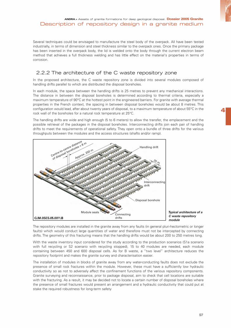
4
Description of repository design in a granite medium
97
Several techniques could be envisaged to manufacture the steel body of the overpack. All have been testedindustrially, in terms of dimension and steel thickness similar to the overpack ones. Once the primary packagehas been inserted in the overpack body, the lid is welded onto the body through the current electron beammethod that achieves a full thickness welding and has little effect on the material's properties in terms ofcorrosion.
2.2.2 The architecture of the C waste repository zone In the proposed architecture, the C waste repository zone is divided into several modules composed ofhandling drifts parallel to which are distributed the disposal boreholes.
In each module, the space between the handling drifts is 25 metres to prevent any mechanical interactions.The distance in between the disposal boreholes is determined according to thermal criteria, especially amaximum temperature of 90°C at the hottest point in the engineered barriers. For granite with average thermalproperties in the French context, the spacing in between disposal boreholes would be about 8 metres. Thisconfiguration would lead, after about twenty years of disposal, to a maximum temperature of about 55°C in therock wall of the boreholes for a natural rock temperature at 25°C.
The handling drifts are wide and high enough (5 to 6 meters) to allow the transfer, the emplacement and thepossible retrieval of the packages in the disposal boreholes. Interconnecting drifts join each pair of handlingdrifts to meet the requirements of operational safety. They open onto a bundle of three drifts for the variousthroughputs between the modules and the access structures (shafts and/or ramp).
Typical architecture of a
C waste repository
module
The repository modules are installed in the granite away from any faults (in general pluri-hectometric or longerfaults) which would conduct large quantities of water and therefore must not be intercepted by connectingdrifts. The geometry of this fracturing means that the handling drifts would be about 200 to 250 metres long.
With the waste inventory input considered for the study according to the production scenarios (S1a scenariowith full recycling or S2 scenario with recycling stopped), 15 to 40 modules are needed, each modulecontaining between 450 and 600 disposal cells. As for B waste, a “two level” architecture reduces therepository footprint and makes the granite survey and characterisation easier.
The installation of modules in blocks of granite away from any water-conducting faults does not exclude thepresence of small rock fractures within the module. However, these must have a sufficiently low hydraulicconductivity so as not to adversely affect the confinement functions of the various repository components.Granite surveying and reconnaissance, prior to package disposal, aim to check that cell locations are suitablewith the fracturing. As a result, it may be decided not to locate a certain number of disposal boreholes wherethe presence of small fractures would present an arrangement and a hydraulic conductivity that could put atstake the required robustness for long-term safety
G.IM.0SES.05.00 1 1.B
Centre-to-centre distance
of disposal boreholes = 8 m
Approx. 250 m
Connecting drifts
Module seals
Interconnectingdrift
Disposal borehole
Handling drift
25 m
} }
ANDRA > Assets of granite formations for deep geological disposal. Dossier 2005 Granite
G.IM.0SES.05.00 1 1.B
Centre-to-centre distance
of disposal boreholes = 8 m
Approx. 250 m
Connecting drifts
Module seals
Interconnecting drift
Disposal borehole
Handling drift
25 m
} }
95467_Chap4_Granit.qxd 11/04/07 14:34 Page 97

Ongoing survey of granite for locating disposal boreholes of a C waste or spent fuel module
During the repository construction stage, the aim of the geological reconnaissance is to specify thedisposal borehole location and to check that this location is suitable with the granite fracturing. Firstly, exploration boreholes are drilled from the repository connecting drift in the axis of a few of thefuture handling drifts (for example one out of five or ten) along which the disposal boreholes will bedistributed. Between these exploration boreholes, geophysical surveys (e.g. seismic tomography)identify the paths of any fractures in the granite rock. A diagram of the fracturing network is thenproduced using the geophysical data, geological surveys and hydrogeological measurement performedin these exploration boreholes. From this diagram, new exploration boreholes are then drilled in the axisof each of the future handling drifts. Their survey includes measurements aiming at testing the hydraulicconductivity of possible fractures. On these bases, it is decided whether or not to excavate the handlingdrifts.Secondly, in the handling drifts, a geological survey is performed along the walls to confirm thecorrectness of the fracturing diagram. The planned locations for the disposal boreholes are then testedby vertical exploration of a length equivalent to that proposed for the disposal boreholes. Tests of waterflow and geological survey of the small fracturing are then conducted to ensure the correct location ofthe disposal boreholes, i.e. their compliance with criteria established throughout the study stages priorto the repository construction. If compliance is not confirmed with sufficient confidence, the location willbe ruled out. A 10% exclusion rate was considered to be likely in the SKB studies for the design of theKBS-3 spent fuel repository (Sweden). After drilling the disposal boreholes, a final check is made on the basis of geological surveys andmeasurements of possible water flow rates in the disposal boreholes to guarantee their locationsuitability.
Principle for determining the
degree of fracturing through the
ongoing method (as excavation
works progress)
98
ANDRA > Assets of granite formations for deep geological disposal. Dossier 2005 Granite
95467_Chap4_Granit.qxd 11/04/07 14:34 Page 98

4
Description of repository design in a granite medium
99
2.3 The disposal of spent fuelThe architecture proposed for the spent fuel disposal is based on the same principles as that of the C wastedisposal. The exothermal nature of the packages in practice leads to the management of the repositoryfootprint using the same plan with modules installed away from water-conducting faults. The disposalboreholes are distributed along parallel handling drifts about 25 metres apart. The distance between disposalboreholes would be 10 to 15 m.
However, unlike C waste, spent fuel is not confined in a glass matrix: the spent fuel assemblies are thereforelikely to release radioelements more quickly in case of water ingress from possible nearby faults. In fact,because of the footprint needed for spent fuel disposal (several km2), the presence, near the disposal cells, offractures conducting small quantities of water cannot be ruled out, even though the process of cells locationavoids them as for the C waste case. The disposal packages must therefore be designed so that spent fuelassemblies are protected from water arrival for a sufficiently long time to withstand a possible failure of thedrift sealing arrangements.
In the context of a study without any specific site, Andra has relied on the experience acquired with the "KBS-3" concept with a long-lasting leak-proof copper container. This concept was adopted in the 1980s bySweden and became then the common reference for both SKB (Sweden) and Posiva (Finland) for their studiesof a repository in a granite medium. Copper is a thermodynamically stable metal in environmental chemicalconditions similar to those occurring underground in a granite massif. The repository is designed so that theseconditions are maintained for the time scale considered by the safety analyses, i.e. several hundred thousand years.
The Swedish KBS-3 concept for spent fuel (SKB data)
Full-scale experiments of the main components of this concept are carried out in the Aspö laboratory.
The container durability requirements could be lower in the case of certain granite sites because of their geolo-gical nature. The Spanish organisation Enresa is currently studying the possibility of a spent fuel disposalconcept with a durable steel container that would last for a few thousand years.
2.3.1 The spent fuel disposal cell: small boreholes with a copper container and a clay buffer(the "KBS-3" concept)
In the Swedish KBS-3 concept, the disposal cell is a small vertical pit (disposal borehole) containing a copperspent fuel container.
For several years, SKB and Posiva are also studying the possibility of disposal in horizontal tunnels, whichreduce the volume of rock to be excavated. Andra monitors these studies; however, the many results alreadyobtained on the “KBS-3” vertical concept have led us, at this stage, to propose vertical disposal boreholes as
ANDRA > Assets of granite formations for deep geological disposal. Dossier 2005 Granite
95467_Chap4_Granit.qxd 11/04/07 14:34 Page 99

the reference option. Furthermore, as for C waste, the adaptation of the location of a vertical cell to the smallfracturing of the granite is simpler in the case of a rather vertical fracturing configuration, which is generally thecase in the French geological context.
• The disposal boreholes
The design of the disposal boreholes avoids components, especially metallic ones, that are likely to chemicallyinteract with the copper container and to adversely affect its long term leak-tightness function. As for C waste,the swelling clay buffer ensures a hydraulic transfer regime by diffusion in the disposal boreholes even if thereare small fractures in their walls. It helps to maintain chemical environmental condition compatible with thecopper of the container while providing a chemical buffer to any water coming from the granite and the handlingdrifts. The bentonite rings around the containers have a thickness of about 35 centimetres.The reduced dimensions of the disposal boreholes (about 8 m long and less than 2 m in diameter) mean thatthey can be excavated with a boring machine, as for C waste, thus greatly limiting the damage to the rock wall.The disposal boreholes are dead-ended, opening at their top onto a handling drift allowing the transfer andemplacement of the spent fuel containers.
Spent fuels disposal cells
• The spent fuel container: SKB studies and transposition to French spent fuel
The spent fuel container designed by SKB comprises a cylindrical copper shell (envelope) and an internalmechanically resistant cast iron structure (called the "insert").
View of the copper envelope and insert for BWR assemblies
(source SKB)
G.IM.0SES.05.0050.A
Disposal borehole for CU2 packages
Compacted backfill
Disposal packages
Concrete base
Bentonite engineered barrier
Disposal borehole for CU1 packages
7.50
m
E 1.35 m
5.50 m
5.50
m
5.50
m
5.50 m
8.25
m
E 1.85 m
1
1 1
2
2 2
3
3
3
4
4 4
100
ANDRA > Assets of granite formations for deep geological disposal. Dossier 2005 Granite
envelope insert (12 BWR assemblies)
lid
95467_Chap4_Granit.qxd 11/04/07 14:34 Page 100

4
Description of repository design in a granite medium
101
The copper envelope consists of a cylindrical body onto which are welded a bottom and a lid. Its thickness (50 mm) allows the container to withstand a hydrostatic pressure of more than 5 MPa and a swelling pressureof the clay buffer engineered barrier of about 7 MPa. The mechanical strength of the package is ensured by thedeformation of the envelope, which is then pressed against an internal rigid insert but without degradation ofthe envelope integrity performance. The feasibility of manufacturing tubes 50 mm thick has been demonstratedby SKB for various metallurgical manufacturing processes: manufacturing by extrusion, by drilling and drawingor by forging.
The cast iron insert is dimensioned to achieve, on one hand the container mechanical resistance and also onthe other hand, the system non-criticality. It is designed in Sweden to house 12 type BWR spent fuelassemblies or 4 type PWR spent fuel assemblies (analogous to French REP spent fuel). This number iscompatible with the maximum temperature criterion of 90°C at the surface of packages in the disposalboreholes after their emplacement.
The transposition to French spent fuel leads to an insert design with housing for 4 UOX (CU1) assemblies or asingle MOX (CU2) assembly. The thickness of the cast iron in between the housings is designed to prevent anyrisk of criticality.
The container diameter is 1.15 m for CU1 and 0.65 m for CU2. Its length also depends on the fuel type:4.50 m or 5.25 m.
Welding on of the lid, after spent fuel assemblies emplacement, has been largely studied by SKB. Varioustechniques have been tested: electron beam and friction. The tests showed that they are compatible with anindustrial manufacturing process in a nuclear context.
3The reversibleoperation of therepository
The reversibility of a repository operation can be defined in terms of its ability to be managed in a progressiveand flexible manner in such a way as to leave freedom of choice to future generations. With this aim in mind,the disposal process can be broken down into successive stages which, from the construction of the firstmodules to the eventual closing of a repository module or zone, provide the possibility of a stand-by orobservation period before deciding to move on to the next stage or to reverse the disposal process. Movingfrom one stage to the next is not a definitive choice - turning the page - but a reasoned choice, in full knowledgeof scientific, technical, economic, social and environmental parameters, and the consequences of the passingonto the next stage.
Reversibility thus means the development of a flexible approach, with periods whose length can be adaptedand which is best understood in terms of levels. In order to propose such an approach, Andra studies andresearch consisted of:
- analysing the main stages of the repository life and the associated time scales, in order to determine the keystages that need a human intervention,
- figuring out a staged management of the repository, with decision milestones. The passage from one stageto another should make the repository increasingly more passive, while gradually decreasing the level ofreversibility and consequently the monitoring and maintenance requirements.
Andra has taken these objectives into account in the design options, notably by means of a modulararchitecture, a search for a simplification of the operations to be conducted underground, by the dimensionsand the choice of durable materials. However, reversibility in no way represents a compromise as far as thesafety objectives are concerned: the aim of reversibility does not include any technical measures that couldsignificantly interfere with a safety function.
Reversibility is also made possible by knowing the evolution of the state of the engineered structures and thedefinition of means of actions, on a time scale of at least centuries: that has led to the study of operational
ANDRA > Assets of granite formations for deep geological disposal. Dossier 2005 Granite
95467_Chap4_Granit.qxd 11/04/07 14:34 Page 101

systems for repository management, notably package retrievability and observation instrumentation whichcould be integrated within the structures.
3.1 The activities carried out in the repository installations
3.1.1 The activitiesThe activities carried out in the repository involve structures construction, nuclear operations and structures closure.
Because of the overall duration of these phases and the aim of proposing a flexible operating plan for therepository, these different activities can take place simultaneously. Fields such as maintenance, monitoring andobservation for the purpose of the reversible management of the repository complement the main activities.
• Progressive construction
After an initial construction phase, i.e. the construction of the structures and equipment necessary for the firstwaste package disposal (surface installations, surface-underground connecting structures, first packagedisposal module and access drifts to this module), construction work can be organised in a flexible way:disposal cells, modules and drifts can be constructed and fitted out as required, i.e. at the desired operatingrate. "Ongoing" survey of granite is carried out during the construction phase.
• Nuclear operation
They include nuclear operations in the surface installations (primary waste package reception and conditioningin waste disposal packages) and in the underground installations (transferring packages inside the undergroundinstallations, emplacing them inside the disposal cells and, if required, retrieving them).
Nuclear operation is characterised by similar constraints to those of current nuclear installations (specificradiological protection equipment, zoning according to the degree of risk of contamination and exposure, etc.).The primary waste packages delivered to the repository site are removed from their shipping casks and thenplaced in waste disposal package in the surface installations. Each waste disposal package is then transferredinside a cask, which provides radiological protection for the personnel from the time the package leaves thebuilding until it reaches the underground installations via the waste package transfer shaft. Underground, thecask is docked with the cell entrance: by means of remote-controlled equipment, the disposal package isextracted from the cask and put in its final place in the cell.
Progressive operations over a long period
The industrial commissioning of a repository starts with the arrival, on site, of the first packages and theiremplacement in the repository inside the first structures constructed. Considering reasonable technicalhypotheses for the packages reception rate, the operation of the repository could last from severaldecades to a century. Emplacing the waste packages in the repository progressively and over a ratherlong period offers flexibility for the management of the repository development and allows the feedbackof lessons learnt. This allows a step-wise decision-making process and is favourable for reversibility.
102
ANDRA > Assets of granite formations for deep geological disposal. Dossier 2005 Granite
95467_Chap4_Granit.qxd 11/04/07 14:34 Page 102

4
Description of repository design in a granite medium
103
Diagram of the principle of nuclear operation of the repository
• Structure closure
Unlike a storage facility, a reversible repository can be made passive, i.e. constituting a robust and safe systemin the long term not requiring any human intervention after its closure.
Closure therefore consists of putting in place the various seals (swelling clay plug in the cells and drifts) andbackfilling the drifts within the framework of a staged process complying with the reversibility requirement.
• Related activities: monitoring, maintenance and observation
The aim of monitoring is to guarantee operational safety, in particular for the protection of personnel (workingconditions) and the environment during operation. Beyond monitoring, the aim of observation is to record therepository behaviour, by learning about phenomena and following their evolution, to provide scientific andtechnical information on which to base the reversible management of the repository and help in decision-making.Monitoring and observation are closely linked and fulfil the same motivation: increasing confidence in therepository process and control.
• The maintenance of the underground structures
Together with monitoring and observation, it helps to guarantee the preservation of the functions allocated to thestructures throughout the repository operation, i.e. until the closure stages. This activity makes use of normal civilengineering methods, particularly for the access to underground structures. It has the purpose of ensuring correctand completely safe operation of the equipment used for package emplacement or their possible retrieval.
ANDRA > Assets of granite formations for deep geological disposal. Dossier 2005 Granite
95467_Chap4_Granit.qxd 11/04/07 14:34 Page 103
3.1.2 A reversible operationThe reversibility approach proposed by Andra goes beyond just the technological possibility of retrievingpackages and can be defined as the possibility of progressively and flexibly managing the repository. Thepurpose is to be able to integrate feedback and technical advances into repository management and, moregenerally, to leave future generations with a freedom of decision for the management of the radioactive waste.
• A staged process
Andra has opted not to fix the duration of reversibility from the outset, but rather to consider levels of reversi-bility. The aim is to offer maximum flexibility for the management of each stage, with particular emphasis onthe possibility of maintaining the current state before deciding to pass to the next stage or return to thepreceding one.
The repository management process is thus designed as a succession of stages to be passed through, withouta preconceived duration. The passage from one stage to another is neither final nor laid down in a fixedoperating plan. On the contrary, each stage is associated with choices: return to the preceding stage,maintaining the current state, passage toward less reversibility. The repository design (modular architecture,the aim of simplifying the operations carried out, the dimensioning and the choice of durable materials etc.) hasthe purpose of providing the greatest possible level of choice.
• The stages in the repository management process
Several stages can be identified in the repository management process and its progressive closure, turning itinto a passive and long-term safe installation.
- "After emplacing the packages": the cells are filled with disposal packages but not sealed. Devices at the headof the cells protect the personnel present in the access drifts to the cells. The drifts are ventilated and all theunderground infrastructures are accessible. This phase is comparable to a storage configuration.
- "After sealing the cell": this stage starts after cell closure with a swelling clay plug. The cell access drifts areventilated and the sealed cell heads are accessible.
- "After module closure": this stage starts after sealing and backfilling of all the components in a module.Module closure includes backfilling the internal access drifts connected to it. The connecting drifts that leadto the module remain ventilated and accessible.
- "After repository zone closure": this stage starts after backfilling and sealing of the connecting drifts within arepository zone. The main connecting drifts that allow access to the repository zone remain ventilated andaccessible.
- "Post-closure": this stage starts after sealing and backfilling the shafts and corresponds to the end of therepository management process. The repository is then in "post-closure" configuration. After closure, anobservation period could be considered for the repository and its environment. The installation is madecompletely passive; i.e. it provides protection for man and the environment without any human intervention.
The management of co-activity in the underground installations
Management of the coexistence of nuclear and non nuclear activities (co-activity) and the design of theaccess drifts are based on two fundamental principles:
- The separation of nuclear operation activities, characterised by special risks and constraints(radioprotection, transport safety, etc.), from the activities of construction/closure, to avoid anyoperational interference. This separation principle means that the option of having two dedicatedthroughput circuits was chosen: one for nuclear operation activities, especially the transport of caskscontaining the packages, which is organised around the waste transfer shaft and package transfer drifts(nuclear operation); the other for the activities of construction/closure, which is organised around theservice shaft and works drifts.
- The progressiveness of construction and operation, which offers management flexibility (particularly thepossibility of modifying the repository design or its management mode by taking operating feedback intoaccount).
104
ANDRA > Assets of granite formations for deep geological disposal. Dossier 2005 Granite
95467_Chap4_Granit.qxd 11/04/07 14:34 Page 104

4
Description of repository design in a granite medium
105
The whole process could take place over a period lasting from several decades to several hundred years ifrequired. The progressiveness of closure gives the possibility of putting into place a staged decision-makingprocess and keeps at all times the possibility of returning to the preceding stage. The progressive operatingplan outlined above is by no means the only possible scheme; more stages or different durations could beconsidered. The modular design proposed for the repository and the flexibility offered for its operating modeallow the operating plan to be adapted by taking into account the knowledge of the repository’s conditionprovided by observation.
Stages in the operation and closure of a repository
ANDRA > Assets of granite formations for deep geological disposal. Dossier 2005 Granite
95467_Chap4_Granit.qxd 11/04/07 14:34 Page 105

• A programme of in situ observations to contribute to the repository reversible management
The choices of repository management are based on an understanding of its evolution over several centuries: theintegration of observation equipment has the purpose of contributing to the management of the reversible disposalprocess.
This consists of monitoring the evolution of the different structures and their environment, in order to ensure theirdurability and to detect any possible need for action (e.g. maintenance) to keep open the different managementoptions: maintaining a structure in good condition for a certain period of time, passage to the next stage by sealing thestructure, return to the preceding stage by re-establishing the access to this structure. It provides as well feedback forimproving the repository design and management.
Observation also provides data for understanding the conditions for any retrieval of the disposal packages. Moregenerally, observation allows us to check that the operation conforms to the forecasts and to improve the repositorybehaviour models using the data acquired.
Observation and measurement devices (deformations, temperature, interstitial pressure, etc.) with their datatransmission network are placed in some B, C and CU instrumented observation cells, in the access structures(shafts or ramps) and drifts, as soon as built, to observe their evolution during operation, before and after their sealing.Other more numerous cells, could also be fitted with lighter instrumentation devices, to confirm the behaviourobserved in the instrumented observation cells and to transpose the results to the entire repository zone concerned.
The variables to be observed during the various stages of the repository process are those that allow us to monitorthe evolution of the structures, to obtain regular assessments of their stability and to quantify the various phenomenaby which a possible return to an earlier stage is governed:
- For the B waste cells, these are the kinetics of water arrival, the production of gas by certain waste and thetemperature for the B cells containing slightly exothermic waste.
- For the C waste (or spent fuel) disposal cells, observations involve the thermal load in and around the cells, themechanical behaviour of the swelling clay buffer and the rise in hydraulic head in the surrounding granite.
- In the case of the access structures (shafts and drifts), observations aim at monitoring the saturation of the backfilland seals and the increase in hydraulic head in the surrounding granite.
The "state of art" developed using the experience gained by monitoring many civil engineering structures and longer-term experiments in underground laboratories outside France suggest a series of good practices:
- The redundancy of structures, by using various technologies or duplicating instruments, to check the consistency ofmeasurements and limit information loss in the event of a defective instrument.
- The choice of high quality and relevant tools in terms of the amplitude to be measured and the expected precision.
- An appropriate distribution of the observation equipment, particularly by using preliminary modelling.
- Integration of observation equipment as from the design stage.
Monitoring equipment suitable for the repository
Several measurement technologies are used in civil engineering structures and underground laboratories:
- Temperature: vibrating wire sensors (localized measurement), optical fibres (measurement on long profiles),
- Deformations, mechanical displacements and strains: vibrating wire extensometers (measurement of localdeformations) and long-base ones for bore-holes or backfill (deformations over larger distances), verticalpendulums (monitoring displacements in three dimensions),
- Water pressure and flow rate: interstitial pressure vibrating wire pressure cells,
- Relative humidity of engineered barriers, backfill and seals: condensation dew-point hygrometers.
- Concentrations of toxic gases, corrosion, contamination: hydrogen detector, visual inspection, sampling,ultra-sonic measurements and reference samples for corrosion, mass spectrometry for radioactive conta-mination.
- Transmission and centralisation equipment: electrical cables and, above all, optical fibre sensors and lowfrequency or very low frequency electromagnetic (wireless) transmission
106
ANDRA > Assets of granite formations for deep geological disposal. Dossier 2005 Granite
95467_Chap4_Granit.qxd 11/04/07 14:34 Page 106

4
Description of repository design in a granite medium
107
3.2 The reversible closure of the underground structures: the degree of reversibility
The staged closure of the underground structures leads to the passage to a lesser degree of reversibility. Thestages in the process are similar for all packages but there can however be differences. These are caused bothby the architectures of the various repository zones and by properties of their engineered components: seals,backfill, engineered barriers, disposal packages, etc.
3.2.1 The B waste disposal structuresAs long as the tunnels remain unsealed, the reversibility of B waste disposal is total. The packages can beretrieved using the same method as those to emplace them, i.e. a remote-controlled fork-lift truck. The mainte-nance and monitoring relating to operation can be continued for as long as one wishes to keep the tunnels open.
The B waste repository: emplacement and possible retrieval of package
After closure of the tunnels (disposal cells), the installations at the tunnel head are dismantled, a seal is installedin the access drift and the ventilation is stopped. The evacuation of any water coming from small fractures inthe granite of the tunnel walls is stopped. The stoppage of the ventilation can lead to an accumulation of gasproduced by the packages. Water can also accumulate on the tunnel floor.
In these conditions, package retrieval would require prior operations, and notably:
- drilling boreholes through the seal to evacuate the gas that has accumulated in the tunnels, or water on thecell floor,
- re-establishment of the ventilation,
- dismantling the seal,
- re-equipping the tunnel head.
After reconstruction of the airlock and reinstallation of the ventilation in the disposal chamber, the packagescould be removed using the same equipment as that used to install them, as the durability of the concrete ofthe packages ensures their integrity for several centuries.
Furthermore, the tunnel seal does not affect the possibility of operating in other tunnels, which ensures thatthe repository can be managed in a flexible way.
ANDRA > Assets of granite formations for deep geological disposal. Dossier 2005 Granite
95467_Chap4_Granit.qxd 11/04/07 14:34 Page 107

In the next stages, the progressive closure of the disposal tunnels access drifts, their backfilling and sealingreduce the accessibility to the packages. The dismantling of the seals and the backfill would require reinstallingthe ventilation and water evacuation systems, which would involve standard and proven mining technology ina granite medium.
3.2.2 The C waste disposal structuresAs for B waste, the reversibility of C waste disposal is total as long as the disposal boreholes are not sealedand the handling drifts are not backfilled. It would require maintaining the ventilation and drainage in thehandling drifts.
The possible retrieval of packages would be performed using the same equipment as that used for theiremplacement, i.e. a remote-controlled vertical handling system similar to that used for many years on theCogema facility at La Hague.
The steel sleeve would allow the emplacement or possible retrieval of waste packages through one or morestages depending on the number of packages per borehole. The operating plug ensures a radiologicalprotection function. The swelling clay buffer and the sleeve protect the packages from any water that couldcome from small fractures in the granite wall of the disposal borehole. So long as corrosion has not weakenedthe sleeve mechanical strength (a period of several centuries), the disposal packages remain free within thesleeve.
C waste repository: emplacement and possible retrieval of packages in disposal borehole
The sealing of the disposal boreholes by a bentonite plug plus the backfilling and closure of the handling driftswould reduce the accessibility to the packages and the degree of reversibility. Package retrieval would requireaccess to the disposal boreholes and therefore removal of the backfill. Then the bentonite plug and theoperating plug would have to be removed.
Repository module closure is also accompanied by backfilling of handling and connecting drifts, and theinstallation of seals at key points in the connecting drifts. The ventilation and the pumping of any water likelyto come from small fractures in the drift walls are stopped. Accessing again to the handling drifts would require,as for B waste, reinstalling the ventilation systems, dismantling the seals and removing the backfill.
3.2.3 The spent fuel disposal structures The stages in the process of a possible spent fuel repository are similar to those of a C waste repository.However, the proposed option of a copper container for the spent fuel repository (KBS-3 concept) leads tospecific arrangements in terms of reversibility. The use of copper means that steel components cannot be usedin the disposal boreholes to prevent any chemical interaction that would be likely to adversely affect the
G.IM.0SES.05.0204.A
Emplacement of first package
Emplacement of second package
Operating plugemplacement
108
ANDRA > Assets of granite formations for deep geological disposal. Dossier 2005 Granite
95467_Chap4_Granit.qxd 11/04/07 14:34 Page 108

4
Description of repository design in a granite medium
109
container. The sleeve that makes package retrieval easier cannot therefore be used. Similarly, to prevent anycopper oxidation that could be related to handling drifts continuous ventilation, it may be necessary to closethe disposal boreholes shortly after container emplacement.
In these conditions, the proposed option is to only emplace a single package per disposal borehole to ensureflexible management of the repository process and the organisation of possible package retrieval.
Package handling techniques have been the subject of an in situ demonstration in the Aspö laboratory inSweden. SKB is also testing in the Aspö laboratory the removal of a disposal borehole plug through bentonitedestructuration using a saline solution.
The progressive closure of the spent fuel repository modules uses the same arrangements as those proposedfor C waste.
The KBS-3 concept (Sweden): principle of emplacing spent fuel containers in the disposal borehole (pit)
3.2.4 The main drifts and the surface-underground connecting structures
After repository modules closure, their access is possible through the maintenance of ventilation and waterpumping. This stage can last as long as these technical systems and structure monitoring are still operational.
The following stages consist of closing the repository zones that contain the modules of the same category ofwaste then, the connecting structures between the surface and the repository zones (shafts, ramps, connectingdrifts, etc.). As in the previous stages, the drifts are backfilled and sealed at specific points, particularly in relationto the possible interception of water-conducting faults by the drifts. This is accompanied by the stoppage of theventilation and water pumping.
These stages include the sealing of the exploration boreholes drilled during the granite reconnaissance stageusing swelling clay materials (bentonite) in order to prevent the possible consequences, in terms of long-termsafety, of an uncontrolled hydraulic connection in between structures.
G.IM.0SES.05.0213.B
Shifting the emplacement
machinery
Handling drift
Transfer vehicle
Rotation of the protection cask
Disposal borehole
ANDRA > Assets of granite formations for deep geological disposal. Dossier 2005 Granite
95467_Chap4_Granit.qxd 11/04/07 14:34 Page 109
3.2.5 Conclusion on the reversible management of the repository
Generally speaking, the great mechanical stability of excavations in a granite medium favours the ability toretrieve packages and the flexibility of the disposal process management over very long time periods. The sameis true for the durable disposal containers (several centuries at least for B waste and several thousands of yearsfor C waste, and even longer for spent fuel).
However, structures evolution can eventually influence the adaptability of packages and installations management.This point mainly concerns the swelling, with water arrival, of the engineered barrier clay in spent fuel and Cwaste disposal cells, and for the latter, the slow corrosion of the disposal cell metallic sleeves.
Furthermore, the continuous operation for long periods in underground drifts, in particular the disturbancescaused by ventilation and water pumping (B waste cells, access drifts to cells, connecting drifts), can have ahydrogeological and hydrogeochemical impact on the granite; these disturbances depend on the site contextand, in any case, would appear to be reversible.
In the first stage of the disposal process, the packages can be managed as in a storage facility. They can beretrieved using the same methods as used for their emplacement, in a way that is as flexible as in a storagefacility. Then, as the structures are closed, the degree of reversibility gradually decreases.
For C waste, the design of the disposal cell metallic sleeve involves a durability of at least 200 to 300 yearswithout any particular maintenance, almost independently of whether closure stages have been reached or not.To extend this period, it would be necessary, from a technical viewpoint, to adopt enhanced maintenance ofthe disposal cells. Beyond the sleeve lifetime, package retrieval would require the simultaneous use of morecomplex processes.
Before spent fuel package retrieval, it would involve additional techniques when engineered barrier clay hasbecome hydrated and swollen.
Generally speaking, repository observation would provide a regular re-assessment of the evolution anddurability of the components (swelling of the swelling clay, lifetime of the disposal cell metallic sleeve) and theimpact of the operation on the granite.
A duration of two to three centuries constitutes an envisaged period for managing the disposal process in areversible manner without requiring technically heavy operations.
110
ANDRA > Assets of granite formations for deep geological disposal. Dossier 2005 Granite
95467_Chap4_Granit.qxd 11/04/07 14:34 Page 110
4
Description of repository design in a granite medium
111
ANDRA > Assets of granite formations for deep geological disposal. Dossier 2005 Granite
95467_Chap4_Granit.qxd 11/04/07 14:34 Page 111

112
ANDRA > Assets of granite formations for deep geological disposal. Dossier 2005 Granite
95467_Chap5_GRANITE.qxp 11/04/07 14:44 Page 112

113
5
ANDRA > Assets of granite formations for deep geological disposal. Dossier 2005 Granite
Long-term and safetyp.115 > 1. Evolution of a repository in a granite medium
p.123 > 2. Long-term safety analysis
95467_Chap5_GRANITE.qxp 11/04/07 14:44 Page 113

One of the main purposes of deep geological disposal is to build a facility which, ultimately, would not need humanintervention and evolve passively. This chapter describes the post-closure long-term behaviour of a repository, together with the safety approach andanalyses intended to ensure that the repository will be able to evolve, without human intervention, once closed,while meeting its objectives in terms of protecting man and the environment.
The proposed analytical method - or safety approach - is based on a number of principles that are common to bothclay and granite deep geological disposal studies.
• The safety analysis is based first and foremost on identifying and understanding the phenomena liable to occur ina repository in a granite medium, and on a long-term understanding of the repository and its environment. It drawson scientific research, the results of experiments and simulations, placed in perspective in the form of aphenomenological analysis.
• However, the number and duration of the phenomena occurring in a repository make it a relatively complexsystem. The safety analysis is a tool that, based on a thorough understanding of the phenomena involved,classifies them hierarchically, by highlighting the crucial points and representing the repository history in asimplified but robust and realistic way. From the repository rich and complex phenomenology, the analysisderives a conservative representation, known as the normal evolution scenario, which can be represented inthe form of robust, simplified models with numerical simulations. The analysis then uses this representation asa basis for testing the suitability of the safety functions assigned to the various components and assesses therepository system's overall performance. It takes into consideration the uncertainties relating to the repositoryevolution, modelling validity limits and the possible parameter variations. This approach not only ranks the mostsignificant uncertainties but also uses an altered evolution scenario, to cover situations outside the expectedevolution, either incidents occurring independently of the designer's intentions (e.g. intrusion into therepository), or premature failures of certain components. The analysis yields a set of calculations andassessments intended to ensure that the repository complies with the objectives in terms of protecting manand the environment.
Unless a specific site is considered, the long-term safety analysis of a repository in a granite medium cannotclaim to be thorough enough to reach conclusions regarding a facility robustness or the suitability of a particularsite. With respect to impact assessment, quantified radioprotection objectives would be premature, in view ofthe lack of site-specific data. Therefore, the analysis can only be considered as preliminary.In this context, the safety analysis was performed on the basis of generic repository architectures that allowfor variability in the properties of the granites in French geological formations. The phenomenological analysisis based on the existing corpus of knowledge about granite media and the behaviour of engineered repositorycomponents, and in particular on information derived from experiments conducted in underground laboratoriesabroad.Structured accordingly, the analysis made possible to identify and address the various issues relating to thesafety of a repository in a granite medium, verify that none of the issues raised would rule out feasibility andhighlight the key points in terms of both repository design and necessary site-specific work
Safety approach references
As the safety approach in “Dossier 2005 Granite” was not performed in the context of a site selectionprocess or of the assessment of a particular site, it cannot refer to all aspects of Basic Safety Rule RFSIII.2.f. issued by the Nuclear Safety Authority in 1991 and relating to such approaches. However, RFSIII.2.f. describes a number of methodological principles and design options, that are appropriate even atan earlier stage. For example, the general objective of making all necessary provisions, to limit therepository impact and to consider its impact in both "normal" and "incident" situations, remains a relevantconsideration at the study stage.In general, RFS III.2.f. recommendations have been taken into consideration in the studies, whileappropriately adapting their interpretation to the nature of the dossier. In addition to the Basic Safety Rule, the internationally-developed principles (e.g. the AIEA draft safetyrequirement and the OECD/NEA definition of the "safety case") were also embodied when developingthe safety approach for “Dossier 2005 Granite”. Although the safety approach does not constitute a"safety case" in the NEA sense, the main aspects covered by these documents (the importance of thearguments clarity and transparency, the need to record and trace data sources, the emphasis onuncertainty management, etc.) were implemented when producing this dossier.
114
ANDRA > Assets of granite formations for deep geological disposal. Dossier 2005 Granite
95467_Chap5_GRANITE.qxp 11/04/07 14:44 Page 114

5
115
1Evolution of a repositoryin a granite medium
Understanding the phenomenological evolution of the repository and its geological and surface environment isclosely linked for the design process, and is one of the key aspects of the repository safety assessment.Understanding this evolution, notably exhaustively, makes possible to describe the processes that influenceradionuclide behaviour and migration, and therefore to ensure that the repository, as per its proposed design,and the geological medium meet the long-term safety requirements.
A repository is a complex system involving multiple components (packages, engineered barriers and thegeological medium) and which is subject to a range of often coupled thermal, hydraulic, chemical andmechanical phenomena. The repository components evolve over time as a result of these phenomena (whichpresent different kinetics).
In order to ascertain this complexity, Andra has broken down the repository evolution into a series of situations,each corresponding to the phenomenological state of a part of the repository or its environment at a particularpoint in the repository life; these situations reflect the thermal, hydraulic, mechanical, chemical and radiologicalphenomena at work, and account for the sequencing and coupling of said phenomena. The analysis concernsnot only the repository construction and operating phases of one or more centuries, but also the post-closurephase, therefore dealing with a timescale of one million years.
The set formed by these situations, known as the Phenomenological Analysis of Repository Situations (PARS)defines the complete, continuous phenomenological evolution of the repository and its geologicalenvironment. The PARS provides the framework for analysing the radionuclide release and transfer phenomenathat must be taken into account in the long-term safety assessments.
1.1 Repository evolution – OverviewWithin all the proposed arrangements of the repository design, compartmentalisation of the undergrounddisposal installations into distinct zones and modules means a phenomenological evolution that is largelyspecific to each individual part of the repository. The influence of the various thermal, mechanical and chemicalphenomena at work is largely limited to the perimeters of the various repository modules.
From a hydraulic perspective, excavating the surface-underground connecting structures, as well as the driftsand underground structures, drains water throughout the repository operational phase. This drainage must beconsidered on the scale of the repository as a whole. At post-closure, separating repository structures by sealsand backfill allows each module to evolve independently.
The compartmentalisation of the proposed architectural structures helps to simplify the analysis. Such ananalysis can be carried out to describe separately the evolution of the repository general infrastructure (shafts,ramps, connecting drifts, etc.) and the evolution of each zone (B, C and spent fuel). Other provisions also helpto simplify the phenomena to be analysed:
- the small number of engineered components in the disposal cells limits the interfaces between differentmaterials and their possible coupling,
- the size of the structures ensures that they remain mechanically stable over the long term, thanks to the greatmechanical strength of granite. The "mechanical" component does not, therefore, govern the evolution of arepository in a granite medium.
- the thermal dimensioning and technical provisions restrict the temperature to domains in which phenomenadescription and modelling are well known. Thus, respecting a maximum temperature of 90°C at all points inthe rock was adopted as a dimensioning criterion for the disposal zones containing exothermic packages.
Long-term safetyANDRA > Assets of granite formations for deep geological disposal. Dossier 2005 Granite
95467_Chap5_GRANITE.qxp 11/04/07 14:44 Page 115
1.1.1 General repository infrastructure (shafts, ramp and connecting drifts) - A short hydraulic transient and very slow long-term chemical evolution
During repository construction and operation, the infrastructure components (shafts, ramp and inter-moduleconnecting drifts) drain granite groundwater via the intercepted water-conducting fractures. This drainagecontinues until the repository is closed. Excavation works lead to a rapid decrease of the hydraulic head in themain intercepted faults, since these faults drain most of the granite groundwater. The hydraulic head in thesmaller fractures then also gradually decreases, after a delay that depends on the fractures interconnection.
Once the structures are closed, the hydraulic head increases in the opposite manner to that described above.After a few months, the hydraulic head in the larger faults reaches a level comparable to the pre-excavationsituation. The hydraulic head in the lower hydraulic transmissivity and smaller fractures, is also graduallyrestored, after a period that depends on the granite fracturing configuration. The underground structuresgradually fill up with water. The very low permeability seals dividing up the infrastructure make the resaturationprocesses for the different areas of the repository mutually independent. Accordingly, structures becomesaturated after a period determined by the density and hydraulic properties of the intercepted fractures and bythe permeability of the backfill put in place. Generally speaking, these periods are of the order of ten years toa few decades. Such periods are short in relation to the timescales of several hundred thousands of years thatare considered in the analysis. The disturbance to the hydraulic state of the granite massif caused by at firstthe hydraulic head loss and then the restoration process is a very short-lived transient. At the scale of thegranite massif, the hydraulic situation returns to a state similar to the situation prevailing prior to constructionof the repository.
The water drainage caused by the repository can lead to transient disturbances in the distribution of thechemical compositions of the granite groundwater. In particular, the original water stratification (the deeper, themore saline the granite groundwater) may be modified during the repository operating phase. The return to theinitial conditions occurs over a longer period (measured in millennia) than the hydraulic head restoration. In theFrench geological context, any such disturbances would scarcely affect the chemical composition of the waterin the repository. Any such modifications would not necessitate special design provisions, notably with regardto the formulation of containers and engineered barriers.
Once the structures are saturated, water movements in the connecting drifts are essentially dependent on thelow permeability of the backfill and the intercepted fractures. Indeed, the damaged granite zone aroundstructure walls created during excavation work has little influence on water flows in the drifts. Tests conductedat the Lac du Bonnet laboratory in Canada have proved the low hydraulic continuity of the damaged zonearound drifts excavated using conventional “drill and blast” (with explosives) techniques. The "ZEDEX"experiment at Äspö laboratory in Sweden also proved the very limited extent of rock damage and low hydraulictransmissivity near structure walls when boring techniques (e.g. microtunneling machines) are used. Thedamaged zone therefore has only a very limited role in the drainage phenomenon. Furthermore, the feasibilityof using very low-permeability seals anchored in the sound rock was demonstrated at the Lac du Bonnetlaboratory ("Tunnel Sealing Experiment"). Such seals restrict water flows between drift sections with a diffusiveor combined diffusive/advective hydraulic regime, corresponding to very slow movements.
Once the drifts have been closed and have resaturated, chemical exchanges take place between granitegroundwater and the backfill. The slightly oxidizing environment (due to ventilation air and the possible arrivalof water from shallower granite) becomes first anoxic, then reducing. Experiments in underground laboratoriesand on granite samples (notably the "REX" experiment at the Äspö laboratory) have demonstrated the naturalability of the minerals in the granite to fix the oxygen of the water. Over the long term, given that the backfillcontains more than 70% of ground granite rock, the water tends to reach a state of equilibrium with the rock,and the chemical exchanges are limited.
Put briefly, infrastructure facilities (shafts, ramp and connecting drifts) evolve very little over the long term: thisis due both to the mechanical stability of the granite rock and the correlated absence of metal ground supports,the very similar composition of backfill and granite, and the very slow kinetic of water movementsunderground.
116
ANDRA > Assets of granite formations for deep geological disposal. Dossier 2005 Granite
95467_Chap5_GRANITE.qxp 11/04/07 14:44 Page 116

5
117
1.1.2 B waste disposal modules - Very slow chemical evolution dominated by the cementitious environment of the waste packages
By design, the tunnels and drifts in a B waste disposal module are located in very low permeability and veryslightly fractured granite blocks. Accordingly, during the module construction and operation, the phenomeno-logical evolution of the disposal tunnels consists only in a very slight drainage of water from the granite via thesmall fractures in the tunnel walls. Water is removed through the ventilation flow or a dedicated pumpingsystem (dewatering system). Any alteration to the concrete disposal containers is restricted to the superficial,negligible effects of ventilation. Any radiolysis gases (e.g. hydrogen) released by certain packages (e.g. B2bituminised waste) are removed by the ventilation flow and therefore do not affect the evolution of thepackages themselves. Stacking slightly exothermic B1 or B5 waste increases the temperature, but the disposaltunnels are dimensioned to not exceed 70°C even when their ventilation system stops operating after packagesemplacement. Peak temperatures are reached within a few years. With the other types of B waste, which arenon-exothermic, there is no significant temperature increase.
Once the disposal tunnels are closed, resaturation begins when the ventilation and dewatering systems areshut down. The resaturation kinetic depends on the density of the small fractures in the tunnel walls. Theprocess may vary from a decade to a few centuries, or even a thousand years with certain fracturing configu-rations. Water gradually fills the tunnels from the bottom upwards. After resaturation, there is no more hydraulichead gradient between the disposal tunnels and the surrounding granite. Consequently, any water movementsare very limited, resulting in a primarily diffusive transfer regime.
In this context, a disposal tunnel evolution is essentially linked to the slow chemical processes in the stackedconcrete disposal packages. From a mechanical perspective, over the very long term (between tens andhundreds of thousands of years), the degradation of the disposal packages can lead to a loss of cohesion ofthe stacks, causing a readjustment of their position in the disposal tunnels. However, any alteration of thedisposal packages has little impact on the nature of the chemical environment in the disposal cells, which isessentially characterised by a reducing, strongly alkaline atmosphere (with the pH decreasing from 12.5 to 10over the aforementioned timescales), which would tend to immobilise most of the radionuclides in the tunnels.
Stages in the concrete degradation process
The alkaline water resulting from the chemical exchanges between the granite groundwater and the disposalpackages concrete can alter the properties of the granite at the repository walls. The small fractures at thetunnel walls are clogged by carbonate precipitation, thereby reducing the transfer potential. This point wasdemonstrated by the Hyperalkaline Plume in Fractured Rock (HPF) experiment carried out in the Grimsellaboratory, Switzerland. However, owing to its mineralogical composition, the granite rock is only superficiallyaffected by the alkaline water.
Long-term safetyANDRA > Assets of granite formations for deep geological disposal. Dossier 2005 Granite
95467_Chap5_GRANITE.qxp 11/04/07 14:44 Page 117

Disposal tunnel sealing may also be affected by water alkalinity, which is liable to alter the properties (very lowpermeability, swelling and retention capacity) and performance of the approximately 10 m long swelling claycore that forms the functional part of the seal. However, the aforementioned disturbance, according to currentestimations, extends for less than 2 metres after a million years. Consequently, most of the seal remainseffective over the long term, helping to maintain a predominantly diffusive transfer regime in the tunnels.
Gas production by packages may also disturb the phenomenological evolution in the disposal tunnels over thelong term. Radiolysis of some waste types (notably bituminised sludge) and moreover corrosion of theengineered components steel (primary waste containers) generate hydrogen. Preliminary assessmentssuggest that the gas pressure could in certain circumstances exceed the natural hydraulic pressure, i.e. 4 - 5MPa. In this case, gaseous hydrogen could be transferred to the small fractures in the granite and through theseal toward the drifts. At this stage, no comprehensive quantitative modelling has been performed; it shouldnevertheless be noted that the repository and its drift network offer a significant expansion volume for gasdispersion. Furthermore, the consequences of the existence of a gaseous phase on radionuclide transportwere studied in the "GAM" experiment at the Grimsel laboratory, Switzerland. This experiment proved thatradionuclide transfer and retention in fractures were largely undisturbed.
In a nutshell, a disposal tunnel evolution is essentially determined by the continuous cementitious environmentof the disposal packages throughout the repository life cycle, which in turn maintains the necessary conditionsfor immobilising radionuclides over very long periods.
1.1.3 Vitrified C waste and spent fuel disposal modules - A thermal phase and a very slow chemical evolutionbuffered by swelling clay engineered barriers
Once closed, the disposal modules gradually resaturate. Water from the granite fractures gradually saturatesthe handling drifts backfill and the plugs and swelling clay buffers in the disposal boreholes along the handlingdrifts. Disposal borehole resaturation may take anything from a decade to a few centuries or longer, dependingon the hydraulic properties of the granite fractures. By design, the disposal boreholes are located in unfracturedor only slightly-fractured granite rock.
• Disposal boreholes and engineered buffers
The transient phenomenon wherein the bentonite rings around the steel overpacks swell is also affected by theheat emitted by C waste packages. Numerous studies and experimental programs in underground laboratorieshave focused on the coupling between thermal phenomena and buffer resaturation. Examples include the"FEBEX" experiments in Grimsel, Switzerland, and the "Prototype Repository" in Äspö, Sweden, which involvesin situ tests of spent fuel disposal concepts, the "TBT" experiment testing the behaviour of bentonite buffersat temperatures approaching or even exceeding 100°C. This research has yielded a thorough understanding ofthe phenomena at work and made it possible to satisfactorily model the swelling, pressurisation and behaviourof swelling clay structures when subjected to thermal load. In this respect, thermally dimensioning structuressuch that the temperature in disposal boreholes is limited to 90°C simplifies the simulations and makes themmore robust. The swelling pressure of the plug and engineered barriers peaks at approximately 5 to 7 MPa.
118
ANDRA > Assets of granite formations for deep geological disposal. Dossier 2005 Granite
95467_Chap5_GRANITE.qxp 11/04/07 14:44 Page 118

5
119
Experiment on swelling clay buffers
As for bentonite, the swelling mechanism for clay has been understood and successfully harnessed fordecades. With regard to the repository studies, controlling the swelling in swelling clay buffers entailsunderstanding the mechanism on the scale of the structures, i.e. demonstrating that:
- the "joints" between the structures elements (i.e. bricks or rings) do not prevent homogeneous swelling,
- the heat released by the packages does not induce phenomena that irreversibly disturb the bufferswelling.
Experiments conducted in underground laboratories since the 1980's have explored these two aspects,initially on a small scale, but subsequently at full scale in conditions equivalent to those prevailing inrepository situations.
The FEBEX experiment at the Grimsel laboratory has been testing the behaviour of a bentonite buffer ina large horizontal structure since 1997. Two heat sources simulate the presence of spent fuel packages. Thewater in the largely unfractured granite resaturates the bentonite, which swells progressively from the outerpart toward the inner part near the package. This swelling has been monitored by instruments throughoutthe experiment, which began in 1997. In 2002, the part of the structure representing the heating packagenearest the entrance to the structure (heating package no. 1) was dismantled (see figure below).
…
Long-term safetyANDRA > Assets of granite formations for deep geological disposal. Dossier 2005 Granite
T e m p s ( j o u r )
d = 2 , 2 8 m
1 7 m
X
S e c t i o n E 1
G . P L . F S T E . 0 5 . 0 1 2 1 . 0
Test zone
Concrete plug
Heating package no.1
Liner Heating package no.2
Seam
Granite
Concrete
Bentonite
Section E1 model
In situ test
Rel
ativ
e hu
mid
ity (
%)
Bentonite
Heated package
Scheme of the Febex experiment at the Grimsel laboratory in Switzerland
Evolution of bentonite resaturation in the buffer
95467_Chap5_GRANITE.qxp 11/04/07 14:44 Page 119

After disposal boreholes resaturation and cell plug and bentonite buffer swelling, water flows through thedisposal boreholes are very limited. Consequently, only very slow diffusive transfers can occur. In the disposalboreholes, the temperature reaches its peak (limited to 90°C by design) a few decades after closure, and then gradually decreases to a level similar to the natural geothermal temperatures, after a few thousand years (C waste case) or around ten thousand years (spent fuel case).
In this configuration, the evolution of the disposal boreholes is limited to the very slow chemical exchangesbetween the water, the disposal packages and the bentonite buffer.
• Overpack and steel sleeve in C waste disposal boreholes
With C waste, the disposal package is a 55 mm thick steel overpack. A 25 mm thick steel sleeve is placedbetween the package and the clay buffer for package emplacement and if necessary for easy retrieval. The steeloverpack and sleeve may be altered, first by the partially oxidizing medium present during disposal boreholeresaturation, then by the reducing medium generated by granite groundwater. Oxidizing alteration is minimisedby the cell plug and the bentonite buffer. Over the long term, steel corrosion in reducing medium with theconcomitant production of hydrogen is the main factor in overpack and sleeve alteration. The quantity ofhydrogen gradually increases at higher pressures. As with B waste, the gas pressure could in certaincircumstances exceed the hydrostatic pressure in the disposal boreholes (4 - 5 MPa) and cause gas to betransferred via the clay buffer toward the small fractures or overlying handling drifts.
Any reaction between alteration products (iron oxides) and the clay buffer bentonite can alter the buffer swellingproperties. However, the swelling properties of the whole clay buffer will not be significantly affected as thisalteration phenomenon is limited in terms of penetration and therefore rather superficial when compared tothe buffer thickness (60 cm).
Steel overpacks corrode in a reducing medium at a very slow rate, approximately one micron per year, whichmeans a leak-tightness for several thousand years at the proposed dimensions. Consequently, by the timewater comes into contact with the waste glass matrix, the temperature at the centre of the package will bebelow 50°C, reducing the glass leaching rate and therefore the rate of radionuclide release.
…
Instrument-based monitoring of the buffer showed that the swelling is consistent with the predictivemodels taking in account heating by the packages. The experiment confirmed, in situ, previous resultsobtained with samples and on small-scale mock-up tested in laboratory conditions.
Dismantling part of the experimental apparatus also showed that the joints between the bentonite bricksdating from when the buffer was built were no longer noticeable following the swelling process. Thesejoints ceased to be preferential pathways for water in the structure. Swelling was complete throughoutthe structure.
a/ Prior to swelling, the swelling clay bricks b/ When the structure has resaturated, the joints
present gaps at their joints between bricks are no longer visible, as a
result of the swelling within the buffer
120
ANDRA > Assets of granite formations for deep geological disposal. Dossier 2005 Granite
95467_Chap5_GRANITE.qxp 11/04/07 14:44 Page 120
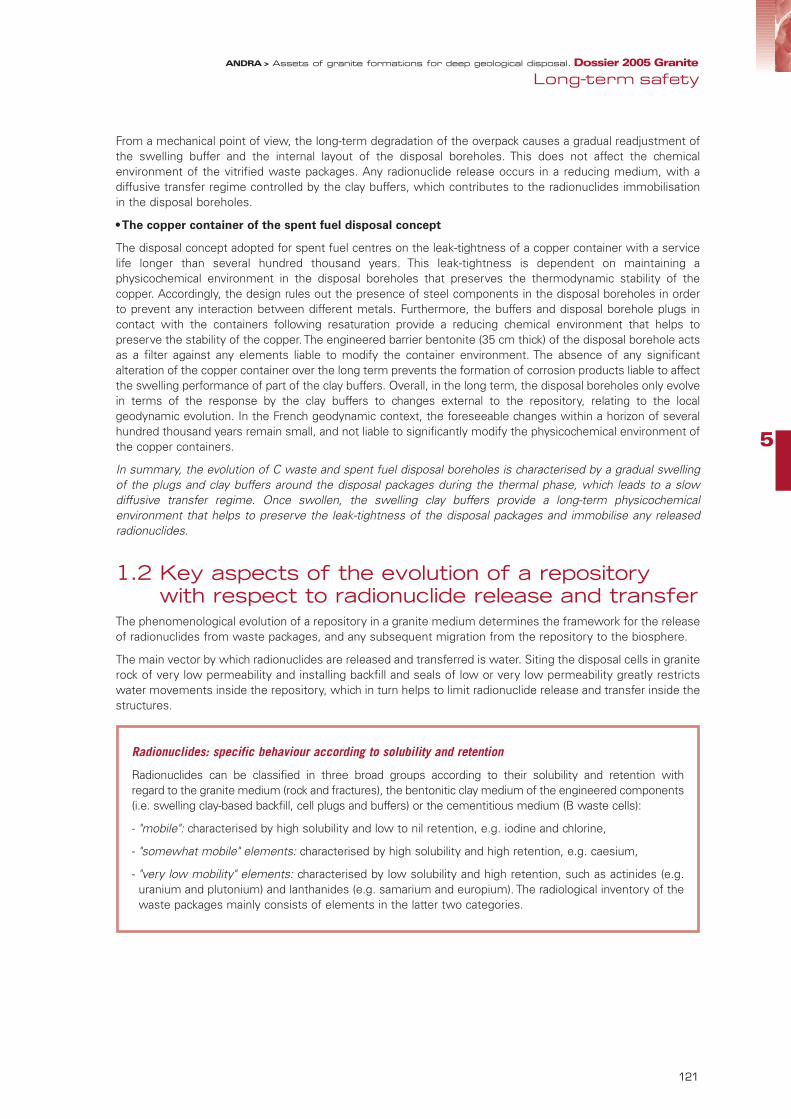
5
121
From a mechanical point of view, the long-term degradation of the overpack causes a gradual readjustment ofthe swelling buffer and the internal layout of the disposal boreholes. This does not affect the chemicalenvironment of the vitrified waste packages. Any radionuclide release occurs in a reducing medium, with adiffusive transfer regime controlled by the clay buffers, which contributes to the radionuclides immobilisationin the disposal boreholes.
• The copper container of the spent fuel disposal concept
The disposal concept adopted for spent fuel centres on the leak-tightness of a copper container with a servicelife longer than several hundred thousand years. This leak-tightness is dependent on maintaining aphysicochemical environment in the disposal boreholes that preserves the thermodynamic stability of thecopper. Accordingly, the design rules out the presence of steel components in the disposal boreholes in orderto prevent any interaction between different metals. Furthermore, the buffers and disposal borehole plugs incontact with the containers following resaturation provide a reducing chemical environment that helps topreserve the stability of the copper. The engineered barrier bentonite (35 cm thick) of the disposal borehole actsas a filter against any elements liable to modify the container environment. The absence of any significantalteration of the copper container over the long term prevents the formation of corrosion products liable to affectthe swelling performance of part of the clay buffers. Overall, in the long term, the disposal boreholes only evolvein terms of the response by the clay buffers to changes external to the repository, relating to the localgeodynamic evolution. In the French geodynamic context, the foreseeable changes within a horizon of severalhundred thousand years remain small, and not liable to significantly modify the physicochemical environment ofthe copper containers.
In summary, the evolution of C waste and spent fuel disposal boreholes is characterised by a gradual swellingof the plugs and clay buffers around the disposal packages during the thermal phase, which leads to a slowdiffusive transfer regime. Once swollen, the swelling clay buffers provide a long-term physicochemicalenvironment that helps to preserve the leak-tightness of the disposal packages and immobilise any releasedradionuclides.
1.2 Key aspects of the evolution of a repository with respect to radionuclide release and transfer
The phenomenological evolution of a repository in a granite medium determines the framework for the releaseof radionuclides from waste packages, and any subsequent migration from the repository to the biosphere.
The main vector by which radionuclides are released and transferred is water. Siting the disposal cells in graniterock of very low permeability and installing backfill and seals of low or very low permeability greatly restrictswater movements inside the repository, which in turn helps to limit radionuclide release and transfer inside thestructures.
Radionuclides: specific behaviour according to solubility and retention
Radionuclides can be classified in three broad groups according to their solubility and retention with regard to the granite medium (rock and fractures), the bentonitic clay medium of the engineered components(i.e. swelling clay-based backfill, cell plugs and buffers) or the cementitious medium (B waste cells):
- "mobile": characterised by high solubility and low to nil retention, e.g. iodine and chlorine,
- "somewhat mobile" elements: characterised by high solubility and high retention, e.g. caesium,
- "very low mobility" elements: characterised by low solubility and high retention, such as actinides (e.g.uranium and plutonium) and lanthanides (e.g. samarium and europium). The radiological inventory of thewaste packages mainly consists of elements in the latter two categories.
Long-term safetyANDRA > Assets of granite formations for deep geological disposal. Dossier 2005 Granite
95467_Chap5_GRANITE.qxp 11/04/07 14:44 Page 121

1.2.1 Slow, limited release outside the repositoryApart from spent fuel disposal, for which the proposed design options involve designing a durable leak-tightcopper container, radionuclides release by waste packages occurs as a result of degradation of the disposalpackages by the water introduced as the cells (B waste disposal tunnels and vitrified C waste disposalboreholes) resaturate.
The length of time before water reaches the waste depends on the disposal cell resaturation kinetic, whichvaries from around ten to a few hundred years, or a thousand years in certain fracturing configurations.
• Slow chemical alteration of the B waste packages in the disposal tunnels
When water comes into contact with waste, only the radioactive elements at the surface of the waste arereleased. The other radionuclides are released as the waste is gradually altered; this process lasts from a fewthousand years with certain metallic waste products (carbon steel, stainless steel, etc.) and bituminised sludge(B2) to a few hundred thousand years with other metallic waste products (zirconium alloy). The radionucliderelease rate depends on the properties of the disposal packages concrete. With standard containers (e.g. forB2 waste), the released rate of radionuclides by the disposal package is essentially restricted by the alkalineproperties of the concrete interstitial water. With containers featuring additional confinement capabilities (B1, B5.2 waste), the concrete hydraulic properties (low permeability and low diffusion coefficient) verysignificantly reduce the rate of radionuclides released, for as long as the aforementioned properties aremaintained (i.e. between a few thousand and around ten thousand years).
• C waste: slow steel overpack corrosion kinetic and slow aqueous dissolution of the glass content
In the C waste disposal boreholes, radionuclide release begins after several thousand years, when overpacksare not anymore leak-tight. As water enters the packages it triggers the glass dissolution process and radionu-clide release. The glass surrounding the C waste continues to dissolve over a period of between a few thousandyears in the case of C0 glass, and a few hundred thousand years in the case of C1, C2, C3 and C4 glass.
• Disposal cells: largely stable physicochemical environments contributing to a low mobility of radionuclides
The physicochemical environments in the disposal cells (for B and C waste) help to ensure high retention andlow solubility for most of the released radionuclides: the majority is adsorbed (trapped) or precipitates insidethe disposal cells. Overall, the concentration of radionuclides in the disposal cell water is low. Combined withan essentially diffusive transfer regime, these phenomena means long enough transfer times between thepackages and the disposal cell rock walls to allow many radionuclides to disappear by radioactive decay.
1.2.2 The role of granite in limiting the transfer of the mostmobile radionuclides toward the environment
The most mobile and long-lived radionuclides are liable to migrate, within the disposal cell, from the disposalpackages up to the rock wall. Granite rock constitutes an effective barrier to radionuclide transfer, on accountof its very low permeability, low porosity and correlated diffusion-inhibiting properties: the diffusion transferkinetics are of the order of one millimetre per thousand or several thousand years. The few small, slightly water-conducting fractures at the rock wall represent the only punctual pathways for radionuclides migration outsidethe cells. Due to the geometric, mineralogical and hydraulic properties of these small fractures, and the smallhydraulic gradients, the flow-rate of radionuclides liable to be transferred outside the cells is small.
Radionuclides can migrate as well outside the disposal cells by diffusion toward the repository drifts, throughthe seals and backfill.
122
ANDRA > Assets of granite formations for deep geological disposal. Dossier 2005 Granite
95467_Chap5_GRANITE.qxp 11/04/07 14:44 Page 122

5
123
In the access drifts, radionuclides can migrate toward the granite via the small or medium-sized fracturesintercepted by the drifts. The low permeability and retention properties of the backfill and seals are additionalfactors that delay the transfer of radionuclides in the repository.
Thus, the radionuclides liable to migrate beyond the repository are the most mobile and long-lived elements.Such elements include iodine 129, chlorine 36, caesium 135, carbon 14 and technetium 99 in the case of Bwaste, and iodine 129, caesium 135, carbon 14 and selenium 79 with C waste.
1.2.3 Radionuclide transfer in the granite massif and the repository environment
After transfer into the small fractures in the granite, radionuclides migrate towards other generally larger andmore hydraulically transmissive fractures (faults). The pathway configuration depends on the fractures networkarrangement and, in particular, the hydraulic interconnections. On the scale of a repository module, especiallywith larger ones (C waste case), there tend to be multiple pathways, which separate the radionuclide flows,allowing them to disperse towards the environment and the various natural surface outlets. This phenomenonmainly concerns the most mobile and long-lived radionuclides, such as iodine 129 and chlorine 36. The otherradionuclides liable to be sorbed or precipitated in fractures (i.e. caesium 135, technetium 99, selenium 79 andcarbon 14) are greatly retarded along their pathways.
2 Long-term safetyanalysis
In principle, the safety approach is based primarily on the repository behaviour, as predicted on the basis of theavailable scientific knowledge. The approach aims to formalise this knowledge within the framework of a safetymodel offering a simplified yet cautious representation of the various phenomena and their progression overtime. It also tests the limits of validity of this representation by evaluating the hypothetical effects on overallperformance, of varying certain parameters. Then, it also examines situations not included in the evolutionmodel predicted or envisaged by the repository designer. Such events are also included in a representation,and their importance in terms of their probability of occurrence with their consequences must be assessed. Inso doing, the approach examines any residual uncertainties and shows how they are accounted for.
The outcome of this work provides ultimately a series of quantitative evaluations, in particular in the form ofindicators reflecting the any impact that the repository may have on man and the environment, or on safetyfunction performance. It evaluates the validity of the safety functions and constitutes a test of the robustnessof the overall system.
Adapting the approach for the generic context of studies of the granite medium
Unless a specific site is studied, the long-term safety assessment of a repository in a granite medium cannotclaim to reach conclusions about a specific granite site, regarding the performance of the studied system.
However, based on the proposed generic repository architectures, the analysis examined all issues relating towaste disposal in a granite medium. In this context of generic studies, the approach also incorporatedexperience feedback from assessments performed abroad, in particular through comparison with the analysesusing international "FEP’s" databases.
Three geological site models were developed, to allow for possible variability in the properties of French granites.These models, based on an analysis of the properties of French granites, are representative of France'sgeological context. Without claiming to exhaustively cover all possible configurations, they make possible toexamine how the main features of a granite massif are involved in evaluating a repository long-term safety. The safety analysis in the Dossier 2005 Granite is methodological in nature; accordingly, Andra extended therange of methods already used, developed certain methods and strove to master the tools availableinternationally with the purpose of evaluating safety in a fractured medium.
Long-term safetyANDRA > Assets of granite formations for deep geological disposal. Dossier 2005 Granite
95467_Chap5_GRANITE.qxp 11/04/07 14:44 Page 123
2.1 From understanding phenomena to performing safety calculations
The phenomenological evolution of a repository in a granite medium is based on existing knowledge of themedium, and reflects the evolution expected by the designer through the design provisions adopted in orderto limit the complexity of the phenomena and uncertainties relating to phenomenological behaviour. In thisrespect it represents the repository evolutions considered to be the most probable. Such evolutions aredescribed as "normal" evolutions. Accordingly, its description, via the phenomenological analysis of repositorysituations (PARS), is an important part of the safety analysis.
Evaluating a repository performance by means of calculations that incorporate the phenomena involved in itsevolution entails integrating them into a simplified and consistent historical representation. This history usescautious assumptions and simplification must be performed in a conservative framework. The history forms ascenario that, while not claiming to represent the future reality, aims to encompass the full range of probablesituations, in a penalizing approach. This scenario forms the basis for a numerical evaluation carried out withdifferent models. Repository performance indicators can then be computed on the basis of these safetycalculations.
2.1.1 Uncertainty management and the various scenariosconsidered in the framework of the generic studies into granite
It is not possible to conduct a meaningful safety analysis and achieve the safety objectives without identifyingand dealing with uncertainties. In the context of generic studies of the granite medium, the objective was i) toidentify the main types of uncertainties that must be treated when designing a repository in a granite medium,ii) and then by analysing them and performing related calculations, to assess the decisive parameters forrepository safety and the associated risks.
The various studied scenarios have showed the role of the main repository components (i.e. the packages,plug, seals and geological medium) with respect to the repository safety functions: "preventing watercirculation in the repository", "limiting radionuclides release and immobilising them in the repository", and"delaying and reducing radionuclide migration". Without claiming to be exhaustive, the scenarios were chosenafter comparing the granite FEP’s base with relevant international FEP’s bases in order to identify groups of"normal evolution FEP’s" and "altered evolution FEP’s" that could be used via encompassing (envelope)scenarios to manage the main uncertainties.
Comparison with international “FEP’s” databases
International FEP’s databases contain a list of site characteristics and repository engineered components("Features"), together with the events ("Events") and phenomena ("Processes") liable to influence therepository evolution. They form a reference base of the elements to be considered in safety analyses.Drawing on the international FEP’s databases, dealing with various types of host formation, a FEP’sdatabase relevant to the generic context of granite was produced. This FEP database was intended to beas exhaustive as possible and consistent with the databases of Andra foreign counterparts. To this end,a systematic comparison with the international databases managed by OECD/NEA was performed. The second step was to compare it with the various components of the proposed generic repositoryarchitectures and the phenomena taken into consideration in the repository "normal" phenomenologicalevolution. Analysing the FEP’s made possible to distinguish those expected to occur ("normal evolutionFEP’s") from those that would only occur as the result of a malfunction ("altered evolution FEP’s").
124
ANDRA > Assets of granite formations for deep geological disposal. Dossier 2005 Granite
95467_Chap5_GRANITE.qxp 11/04/07 14:44 Page 124

5
125
Developing a normal evolution scenario for a repository in granite entails analysing the planned functioning ofthe repository. Various sensitivity calculations can be performed in order to also appraise the uncertaintiesrelating to the characterisation of, on one hand, the granite hydraulic and transport properties and, on the otherhand, the properties of the engineered components. The normal evolution scenario addresses the principaluncertainties involved in the repository design process; these uncertainties would then be managed along thesite reconnaissance process. A series of altered evolution scenarios covered cases involving the failure of the repository's main engineeredcomponents (packages, plugs and seals) as well as a failure in the reconnaissance process of the granite site.To a large extent, these scenarios cover most of the failures and uncertainties relating to the repository process.
Uncertainty classification
A distinction is drawn between uncertainties relating to the repository characteristics (Features), to eventsexternal to the repository (Events) and to the repository phenomenological evolution (Processes).
• Uncertainties relating to the repository characteristics ("Features")
- about the repository project input data, i.e. the inventory and package properties, independently of theirbehaviour in the repository,
- concerning the intrinsic characteristics of the geological medium or a repository component. They mayrelate to a lack of precision of measuring techniques, or to certain parameters that cannot be measureddirectly, which are therefore estimated on the basis of data available in the bibliography. They may alsobe due to spatial variability of the component, with respect to sampling that is necessarily limited. Thisapplies when characterising rock with samples.
- relating to technologies. The technological provisions to be implemented cannot be finalised at thegeneric approach stage. It is therefore important to make allowance for uncertainties due to variabilityof the repository possible operating conditions, and to limited knowledge about the conditions in whicha particular technology can be used in an underground context.
• External events ("Events")
They are a particular form of uncertainty regarding repository evolution. A general distinction is madebetween natural phenomena occurring at the surface (e.g. climatic or tectonic events, etc.), which aretheoretically predictable although often subject to considerable uncertainties, on one hand, and eventsattributable to the actions of man (e.g. intrusion and anthropic effects), which in most cases cannot bepredicted beyond a reasonable horizon, on the other. Such events are treated as uncertainties on accountof the disturbances they entail. Partially conventional approaches are traditionally used to limit the extentof the uncertainties to be taken into account. In accordance with RFS III.2.f., future human behaviour isassumed to be largely the same as the current one. On the other hand, it is possible to use a predictiveapproach, based on past evolutions, for most natural phenomena. Even in this case, uncertaintiesregarding the distant future should be taken into account.
• Uncertainties relating to phenomena governing the repository evolution ("Processes")
After obtaining data for all components of the disposal system, it is necessary to understand, andrepresent how they interact and influence the system evolution. Due to the complexity of the involvedphenomena, a detailed understanding of each interaction may not be obtained and therefore an overallrepresentation must be adopted in order to describe at best the functioning of the system. Representingphenomena through modelling is affected by uncertainties to the extent that it proceeds by simplificationwhen compared to a more detailed representation of phenomena. It is particularly the case for coupledphenomena, generally more difficult to represent. This category includes uncertainties resulting from theneed to predict the system behaviour over extended periods, from the limits of validity of modelling orfrom the existence of more than one model representing the same set of empirical observations.
Long-term safetyANDRA > Assets of granite formations for deep geological disposal. Dossier 2005 Granite
95467_Chap5_GRANITE.qxp 11/04/07 14:44 Page 125

2.1.2 The modelling approach• Choice of indicators
Without any specific site, it would be meaningless to evaluate repository safety on the basis of a dose impact,since the calculations must take the site's environmental conditions into consideration. In a context of genericstudies of the granite medium, a series of intermediate indicators were chosen instead, with the aim ofunderstanding the individual functioning of the main repository components:
- indicators relating to the quantities of water transferred in the various parts of the repository assess therepository performance with respect to the "preventing water circulation" safety function,
- the quantity of radionuclides present at certain key points of the repository at different stages of its evolutionassess the confinement performance of the various components, and facilitate the task of identifying overallrobustness factors. This indicator relates more specifically to the "limiting the release of radionuclides andimmobilising them in the repository", and "delaying and reducing radionuclide migration" functions.
• Choice of models and parameters values
As the research is being conducted for generic sites, it is important to specify the conditions in which thegranite massifs were simulated in the calculations.Relatively few massifs in France have been surveyed from a geological and hydrogeological perspective with asufficient level of characterisation in order to enable a modelling approach taking the properties of a particularsite into account. Furthermore, performing the calculation for a specific site would not be consistent with theobjectives of the dossier, which is specifically intended to be generic in nature.
In order to allow for variability in the properties of French granite massifs, three geological site models ("M1","M2" and "M3") were produced, based on a synthesis of available knowledge of French granites in the form ofa typological classification. This typological analysis allows identifying and ranking the granite characteristics forwhich variability is most likely to influence a repository design. The geological site models were developed before the hydrogeological models and radionuclide transfersimulations. They were described precisely enough to ensure their own geologically consistency and tofaithfully reflect configurations representative of the French geological context. In particular, they are inspiredby configurations found in the Massif Central and Armorican Massif. The models were not built with a view tocomparing sites, and they do not claim to exhaustively represent all configurations liable to be encountered.Rather, they provide a realistic basis on which to appraise the role of the various characteristics with respect tohydrogeology and radionuclide transfer in safety analyses.
Accordingly, each model covers:
- different morphostructural configurations, i.e. the relationships between the granite massif, the surfacetopography and the other formations surrounding the granite massifs,
- different fracturing organisations, both for the small fracturing that must be considered on the scale of therepository structures and for the large one treated on the scale of the massif as a whole,
- granites of different lithological and mineralogical types.
Most of the calculations were performed using the M1 and M2 site models.
126
ANDRA > Assets of granite formations for deep geological disposal. Dossier 2005 Granite
95467_Chap5_GRANITE.qxp 11/04/07 14:44 Page 126

5
127
• "Test values" of the granite medium parameters
Certain simplifications were introduced into the geological models during the successive hydrogeologicalmodelling stages, which were conducted on various scales (i.e. region, massif, repository and disposalmodule). It was also necessary to choose which hydraulic and transport parameters to include. Value rangeswere considered both for the variability of the aforementioned parameters for each geological site model andfor the uncertainties relating in particular to the techniques used to survey and characterise the fracturedmedium.
In the context of generic studies of the granite medium, it is not possible, however, to define the degree ofconservatism of the "test values" adopted for the parameters. Such a definition would only become meaningfulif undertaken in conjunction with the survey and characterisation of a specific site. However, a pair of valuesfor the main hydraulic and transport parameters of the granite and fractures was tested in the normal evolutionscenario. The resulting calculations allow appraising the sensitivity of repository performance to the variousstudied parameters, and to establish orders of magnitude for repository performance for the various designoptions and geological site models under consideration.
Main geological characteristics of the three site models
• The "M1" site model
- Large (several thousand km2) hercynian granite massif, having a relatively contrasted topography and a"dome" morphostructural configuration favourable to long repository-to-surface hydraulic transfer times,
- Fracturing organisation characteristic of a tectonic affected by the Alpine orogeny,
- Granite of a type having an "average" mineralogy that is not particularly favourable to fracture clogging byhydrothermal minerals.
• The "M2" site model
- Small (approximately 100 km2) hercynian granite massif, having a relatively uniform topography and a"depression" type morphostructural configuration, not so favourable for long repository-to-surfacehydraulic transfer times,
- Fracturing organisation characteristic of hercynian granite fracturing, moderately affected by the Pyreneanand Alpine tectonics,
- Granite of a type whose mineralogy is favourable to fracture clogging by hydrothermal minerals.
• The "M3" site model
- Medium-sized (a few hundred km2) cadomian granite massif, having a relatively uniform topography andan "inclined plane" type morphostructural configuration moderately favourable to long repository-to-surface hydraulic transfer times,
- Fracturing organisation typical of a cadomian granite affected by the hercynian tectonic and moderatelyaffected by the Pyrenean and Alpine tectonics,
- Granite of a type having an "average" mineralogy that is not particularly favourable to fracture clogging byhydrothermal minerals.
The hydraulic and transport parameters relating to fracturing are established, on the one hand, on the basisof data already obtained in France, notably at the Vienne site (1994-1996), which was studied by Andra,and at the site in Auriat (Creuse département), which was studied by CEA (1980-1981), and, on the otherhand, by comparing the geological characteristics of fracturing in the various site models. A large corpusof international available data (Sweden, Finland, Switzerland and Canada) was also a contribution in orderto confirm the appropriateness of the parameter values selected for the simulations.
The sensitivity of the hydrogeological models and radionuclide transfer simulations to the fractureshydraulic and transport parameters was tested for each of the geological site models.
Long-term safetyANDRA > Assets of granite formations for deep geological disposal. Dossier 2005 Granite
95467_Chap5_GRANITE.qxp 11/04/07 14:44 Page 127

• Architecture modelling
The various components in the generic repository architectures adopted as reference for the safetyassessments are represented by their main radionuclide transport characteristics. These characteristics notablyinclude the hydraulic and transport properties of the disposal packages, plugs and buffers in the disposal cells,and the backfill and seals in the drifts and access structures. For each of these components, the existingknowledge of the materials and experience feedback from foreign safety analyses were used to test at leasttwo models or parameters that enable to characterise the possible variability. The parameters and models arequalified (as "phenomenological", "conservative" or "penalising") according to the degree of conservatism withwhich they cover the uncertainties.
• Modelling radionuclide transfers in granite - in "fracture networks" and in the "equivalent
porous medium"
Modelling the transfer of radionuclides in the fractures in a granite massif requires certain simplifications, which canbe achieved in two ways:
- "fracture network" models consider explicitly the fractures. In this case, the simplification involves grouping fracturestogether into families. Statistical laws are used to distribute their geological, hydraulic and transport propertiesacross the granite massif,
- "equivalent porous medium" models take the simplification process further. The fractures are not explicitly modelled;instead, "equivalent" hydraulic parameters are assigned to the granite massif, or to certain parts of the massif, inorder to implicitly take the fractures into consideration.
At the scale of the repository structures and immediate environment, the granite is represented using "fracturenetwork" models. These fracture network models required the application of statistical distribution laws to assign thegeological and hydogeological fracture properties in each of the studied site models.
At the scale of a site and the granite massif hosting a repository, the geological medium is represented using"equivalent porous medium" models. For each of the studied geological site models, the modelling process includestechniques for maintaining continuity between the different modelling scales of the granite and its fracturing
2.1.3 Simulation and calculation toolsTwo types of simulation tools were used for the calculations. The tools used for "fracture network" simulations are those used internationally for studies of geological disposal. International cooperation initiatives,as notably the "Connectflow" project, address the development of nested "fracture network" and "equivalent
Different types of models and values
• Phenomenological (or best estimate) model: the model that, all other parameters being fixed, isdeemed to yield results fitting at best those obtained by experiments and/or observations. This choiceis theoretically made without reference to any impact. A phenomenological model or value must bebased on a representative number of measurements and a physical argumentation demonstrating thatit is the most representative according to reliable data.
• Conservative model: model used to obtain a calculated impact that falls within a range of high values(with all other parameters fixed elsewhere). In the simplest case, where the impact increases (ordecreases) as the parameter value increases, a value is chosen from the upper (or lower) range ofavailable values. If no measurement is available, the model uses internationally-available data, as longas these data are explicitly presented in the literature and can be transposed to the studied case.
• Penalising model: model not referring to phenomenological knowledge, chosen conventionally to leadwith all certainty to an impact greater than the calculated one with possible values. For example, thismay correspond to a physical limit.
128
ANDRA > Assets of granite formations for deep geological disposal. Dossier 2005 Granite
95467_Chap5_GRANITE.qxp 11/04/07 14:44 Page 128
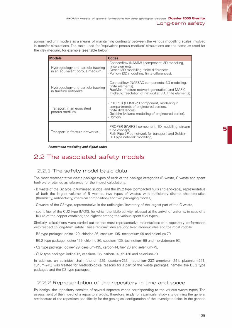
5
129
porousmedium" models as a means of maintaining continuity between the various modelling scales involvedin transfer simulations. The tools used for "equivalent porous medium" simulations are the same as used forthe clay medium, for example (see table below).
Phenomena modelling and digital codes
2.2 The associated safety models
2.2.1 The safety model basic dataThe most representative waste package types of each of the package categories (B waste, C waste and spentfuel) were retained as reference for the impact calculations:
- B waste of the B2 type (bituminised sludge) and the B5.2 type (compacted hulls and end-caps), representativeof both the largest volume of B wastes, two types of wastes with sufficiently distinct characteristics(thermicity, radioactivity, chemical composition) and two packaging modes,
- C waste of the C2 type, representative in the radiological inventory of the largest part of the C waste,
- spent fuel of the CU2 type (MOX), for which the labile activity released at the arrival of water is, in case of afailure of the copper container, the highest among the various spent fuel types.
Similarly, calculations were carried out on the most representative radionuclides of a repository performancewith respect to long-term safety. These radionuclides are long lived radionuclides and the most mobile:
- B2 type package: iodine-129, chlorine-36, caesium-135, technetium-99 and selenium-79,
- B5.2 type package: iodine-129, chlorine-36, caesium-135, technetium-99 and molybdenum-93,
- C2 type package: iodine-129, caesium-135, carbon-14, tin-126 and selenium-79,
- CU2 type package: iodine-12, caesium-135, carbon-14, tin-126 and selenium-79.
In addition, an actinides chain (thorium-229, uranium-233, neptunium-237, americium-241, plutonium-241,curium-245) was treated for methodological reasons for a part of the waste packages, namely, the B5.2 typepackages and the C2 type packages.
2.2.2 Representation of the repository in time and spaceBy design, the repository consists of several separate zones corresponding to the various waste types. Theassessment of the impact of a repository would, therefore, imply for a particular study site defining the generalarchitecture of the repository specifically for the geological configuration of the investigated site. In the generic
Long-term safetyANDRA > Assets of granite formations for deep geological disposal. Dossier 2005 Granite
Models Codes
Hydrogeology and particle trackingin an equivalent porous medium.
- Connectflow (NAMMU component, 3D modelling,finite elements).
- Geoan (3D modelling, finite differences).- Porflow (3D modelling, finite differences).
Hydrogeology and particle trackingin fracture networks.
- Connectflow (NAPSAC components, 3D modelling,finite elements).
- FracMan (fracture network generation) and MAFIC(hydraulic resolution of networks, 3D, finite elements).
Transport in an equivalent porous medium.
- PROPER (COMP-23 component, modelling incompartments of engineered barriers, finite differences).
- Goldsim (volume modelling of engineered barrier).- Porflow
Transport in fracture networks.- PROPER (FARF-31 component, 1D modelling, streamtube concept).
- Path Pipe ( Pipe network for transport) and Goldsim(1D pipe network modelling)
95467_Chap5_GRANITE.qxp 11/04/07 14:44 Page 129

context of the Dossier 2005 Granite, this is not possible. The objective is more generally to identify by meansof calculations and sensitivity analyses the main factors affecting a repository performances. To do this, thescenario treats separately the case of the various types of waste selected: B2 and B5.2 waste, C2 waste andCU2 spent fuel (MOX). The calculations are based on the representation of a repository tunnel of B waste (B2and B5.2 wastes) or a module of C2 waste or spent fuel CU2 (MOX).
For this purpose, it was decided to keep in each of the considered geological site models the sameemplacements for the tunnels (B waste) or repository modules (C waste and spent fuel) considered. Thiscontributes to discriminating more simply in the analysis of the repository performance in granite the factorsrelated to the package types from those related to the geological medium characteristics.
The choice of the emplacements was not aimed at subordinating the repository layout to the characteristics ofthe granite massifs of the three geological models. This would have been illusory considering the genericcharacter of the data used. The emplacements were decided on based on the regional geological andhydrogeological models created for each site model, excluding the proximity of major fault zones andimplantations clearly nonconforming from the hydrogeological viewpoint to the recommendations of the BasicSafety Rule RFS III.2.f. (steep hydraulic gradients, hydraulic unload zones right above the repository, etc.). Twotheoretical emplacements were retained for each site model, which allows analysing how siting affects thelong-term safety of the repository.
From a temporal viewpoint, the assessments are made for a repository after closure, at the scale of a hundredor so years after the start of its construction. This does not presuppose the duration of a reversibiity phasewhich is unknown by definition (century or multi-century). This assumption arbitrarily sets a common referencefor all the calculations. Considering the minor resaturation transient durations mentioned above, the repositoryis assumed to be resaturated as of this date.
With respect to the geodynamic evolutions of a site over the very long term, the calculations do not take intoaccount possible changes in the context of the granite massif which would be derived from them (for example,hydrogeology). Besides the fact that they would be insignificant in the French geological context in the scale oftens to hundreds of thousands of years, such changes would only be justified for a specific site, which isbeyond the generic framework of the studies.
2.2.3 Representation of the waste and radionuclides release• B waste packages
The representation of the packages is different for the two waste types (B2 and B5.2) retained for the calculations.
For the B2 waste (bituminised sludge), the disposal package is assumed as not being water-tight as soon asthe repository is closed, which is a cautious assumption. The concrete container which is not imperviousimposes, however, a chemical environment with a high pH (between 10 and 12.5), limiting the flux of someradionuclides thanks to precipitation and sorption phenomena. The release kinematics is represented by amodel developed around a phenomenology experimentally validated in the laboratory. It is based on water take-up by the bitumen and on the behaviour of radionuclides assimilated with the soluble salts of the bitumenmatrix. In this model, favourable phenomena such as the insolubilisation of the radionuclides during initialwaste treatment are neglected. The proposed release rate leads, at 10,000 years, to a release of 90% of theinitial mass contained in the bitumen.
For the B5.2 waste, the calculations make reference to the case of a container to which complementaryconfinement properties are assigned, that is, a container with hydraulic properties which limit the release ofradionuclides for 10 000 years. The radioactive inventory contained in the zircaloy claddings and the structurewaste causes in contact with water a release which is directly related to the corrosion rate and leads to acomplete release in 100 000 years.
• C waste (vitrified) packages
The vitrified waste is placed in a 55 mm thick carbon steel overpack. This thickness ensures, considering thevariations in the configuration of granite sites in France (particularly with respect to the chemical composition ofthe water), leak-tightness of several thousand years during which no release can take place. On an exploratorybasis, the calculations were made with the same cautious assumption of a release starting after 1 000 years forthe various site models.
The overpack design presents a high robustness with respect to possible manufacture defects. Nevertheless,we have cautiously included the possibility of such a defect in the calculation. At the current stage of the studies,
130
ANDRA > Assets of granite formations for deep geological disposal. Dossier 2005 Granite
95467_Chap5_GRANITE.qxp 11/04/07 14:44 Page 130
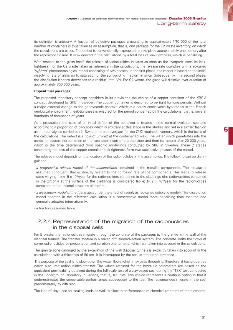
5
131
its definition is arbitrary. A fraction of defective packages amounting to approximately 1/10 000 of the totalnumber of containers is thus taken as an assumption, that is, one package for the C2 waste inventory, on whichthe calculations are based. The defect is conventionally expressed to take place approximately one century afterthe repository closure. It is evidenced in the calculations by a total loss of leak-tightness, which is penalising.
With respect to the glass itself, the release of radionuclides initiates as soon as the overpack loses its leak-tightness. For the C2 waste taken as reference in the calculations, the release rate complies with a so-called"V0S➞Vr" phenomenological model consisting of two phases. In the first phase, the model is based on the initialdissolving rate of glass up to saturation of the surrounding medium in silica. Subsequently, in a second phase,the dissolution kinetics decreases to a residual rate (Vr). For C2 waste, the glass will dissolve over duration ofapproximately 300 000 years.
• Spent fuel packages
The proposed repository concept considers in its provisions the choice of a copper container of the KBS-3concept developed by SKB in Sweden. The copper container is designed to be tight for long periods. Withouta major external change to the geodynamic context, which is a hardly conceivable hypothesis in the Frenchgeological environment, leak-tightness is ensured for the period concerned by the calculations, that is, severalhundreds of thousands of years.
As a precaution, the case of an initial defect of the container is treated in the normal evolution scenarioaccording to a proportion of packages which is arbitrary at this stage in the studies and set in a similar fashionas in the analyses carried out in Sweden to one overpack for the CU2 retained inventory, which is the basis ofthe calculations. The defect is a hole of 5 mm2 at the container lid weld. The water which penetrates into thecontainer causes the corrosion of the cast steel insert of the container and then its rupture after 20 000 years,which is the time determined from specific modellings conducted by SKB in Sweden. These 2 stagesconcerning the loss of the copper container leak-tightness form two successive phases of the model.
The release model depends on the location of the radionuclides in the assemblies. The following can be distin-guished:
- a progressive release model of the radionuclides contained in the metallic components. The release isassumed congruent, that is, directly related to the corrosion rate of the components. This leads to releaserates varying from 5 x 10⁻⁵/year for the radionuclides contained in the claddings (the radionuclides containedin the zirconia at the surface of the claddings is considered labile) to 2 x 10⁻³/year for the radionuclidescontained in the inconel structure elements ;
- a dissolution model of the fuel matrix under the effect of radiolysis (so-called radiolytic model). This dissolutionmodel adopted in the reference calculation is a conservative model more penalising than that the onegenerally adopted internationally;
- a fraction assumed labile.
2.2.4 Representation of the migration of the radionuclides in the disposal cells
For B waste, the radionuclides migrate through the concrete of the packages to the granite in the wall of thedisposal tunnels. The transfer system is a mixed diffusion/advection system. The concrete limits the flows ofsome radionuclides by precipitation and sorption phenomena, which are taken into account in the calculations.
The granite zone damaged by the excavation of the wall disposal tunnels is explicitly taken into account in thecalculations with a thickness of 50 cm. It is interrupted by the seal at the tunnel entrance.
The purpose of the seal is to slow down the water flows which may pass through it. Therefore, it has propertieswhich also limit radionuclides transfer. The values retained for the hydraulic parameters are based on theequivalent permeability obtained during the full-scale test of a clay-based seal during the "TSX" test conductedin the underground laboratory in Canada, that is, 10-11 m/s. This choice represents a cautious option in that itunderestimates the conceivable performances subsequent to the test. The radionuclides migrate in the sealpredominately by diffusion.
The kind of clay used for sealing leads as well to allocate performances of chemical retention of the elements.
Long-term safetyANDRA > Assets of granite formations for deep geological disposal. Dossier 2005 Granite
95467_Chap5_GRANITE.qxp 11/04/07 14:44 Page 131

Scheme of the migration of radionuclides in the B waste disposal tunnels
For C waste, and once the steel overpack lost leak-tightness, the radionuclides migrate through the clay bufferengineered barrier (60 cm thick) to the granite in the wall of the disposal boreholes. Transfer takes place bydiffusion due to the very low permeability of the swelling clay buffer. The radionuclides also migrate partiallyaccording to the same diffusion system to the overlying handling drifts through the disposal cell plug made up ofthe same swelling clay (and 1.50 m thick).
Scheme of the migration of radionuclides in the C waste disposal boreholes and the handling drifts
132
ANDRA > Assets of granite formations for deep geological disposal. Dossier 2005 Granite
95467_Chap5_GRANITE.qxp 11/04/07 14:44 Page 132
5
133
For spent fuel, the figure of the migration of radionuclides is the same as for C waste. It only concerns, forspent fuel, the case of a defective container taken into account in the safety calculations.
2.2.5 Representation of the migration of radionuclides in the drifts and the access structures (shaft, ramp)
Leaving the disposal cells, a fraction of the released elements reach the backfilled drifts of the repository andtransit through these drifts before migrating to the fractures in the granite at the wall of the drifts. The backfillsmade up of crushed granite and bentonite composites have a low permeability (10-10 m/s). The nature of thebackfills is such they are also attributed retention properties. The values of the retention parameters are deter-mined according to a proportion of 15% swelling clay.
The representation of the drifts seals is similar to that of the plugs of the B waste disposal tunnels. Thehydraulic and transport phenomena taken into account in the calculations are of the same kind as thephenomena involved in the seals of the disposal tunnels.
For a repository in the granite medium, the quantity of radionuclides reaching the surface-bottom access struc-tures (shaft and ramp) via the other drifts of the repository is negligible. In fact, the conducting faults inter-cepted by the drifts connecting the repository modules and the access structures form hydraulic barriers to themigration of the radionuclides. Also, the calculations assume that all the radionuclides released by the disposalcells of a module migrate to the granite within the granite block where the module is installed.
2.2.6 Representation of the migration of radionuclides in the granite
The representation of the migration of the radionuclides in the granite is based on the determination ofhydraulic pathways in the network of the fractures of the massif, the repository host formation. These pathwaysare established from hydrogeological models at various scales: at the regional scale, that is, for a dimension ofseveral hundred km2 ; at the repository scale and its surrounding (also denoted the "far field"), that is, for adimension of ten km2 to several tens of km2 ; at the repository module scale (also denoted the "near field"), thatis, for a dimension on the order of a km2 or a fraction of a km2.
• At the scale of the repository module
At the repository module scale, the hydraulic pathways are determined from "fracture network" models, wherethe fractures of various dimensions are explicitly represented based on a stochastic processing of the geologicaland hydrogeological data. The calculations of the migration of radionuclides along these pathways involve:
- advection phenomena (and associated dispersion phenomena), the main driving forces behind watermovements;
- radionuclide diffusion phenomena in the rock on the fracture planes;
- radionuclide retention phenomena by sorption on the minerals of the fractures and the granite rock itself.
The representation of these phenomena in the complexity of a fracture network entails simplifications in thegeometry of the pathways and the exchange surfaces between the water and the fracture planes. The adoptedsimplification modes are based on the results obtained from many experiments conducted in foreignunderground laboratories, particularly within the "TRUE" programme and the modelling exercises of the "AspöTask Force" conducted in international cooperation for fifteen years. The transport parameters for the calculationsare determined from the results of these experiments taking into account, through the various in situ geologicalmodels, the potential variability of the mineralogical characteristics of the fractures and the types of graniterepresented. The variability concerns, in particular, the nature and intensity of the "natural clogging" of thefractures by hydrothermal minerals, as well as the diffusion properties of the rock to the planes of the fractures.
Long-term safetyANDRA > Assets of granite formations for deep geological disposal. Dossier 2005 Granite
95467_Chap5_GRANITE.qxp 11/04/07 14:44 Page 133

Tube model of water and radionuclides pathway in a fracture
• At the scale of the repository and the geological medium
At the scale of the repository and the geological medium, the hydraulic pathways are determined from modelsensuring continuity between the representations in "fracture networks" and the representations in an"equivalent porous medium" on the regional scale. Along the hydraulic pathways, the representation of themigration of the radionuclides is similar to that made at the repository module scale. The migration of radionuclides is represented up to the vicinity of the granite surface. The quantities ofradionuclides are assessed when they enter the superficial part of the altered granite (that is, approximately ahundred - some metres under the surface). This choice allows, in generic assessments, getting arounduncertainties related to the surface and site-specific environment.
The pathways of radionuclides in a fracture network: the "tube" model
The "tube" model generally adopted for radionuclide transfer simulations in a fracture network is based onthe observation that the irregularities of the geometry of a fracture and the fracture/fracture connectionslead to generally channelled flows of water in the fractures (figure below). Tubes form a simplifiedrepresentation of channeling which respond to the digital requirements of the calculations.The water flux from the fractures passes completely into the model’s tubes. Considering the low kineticsof the water movements, the radionuclides migrate by diffusion into the rock altered at the fractures plane:the contact surface between the water and the granite ("wetted surface") is an interacting parameter in thediffusion extent. The granite diffusion coefficients are generally higher at the fractures plane than in thesound rock, which is an element favourable for the retention of radionuclides. The retention parametersselected for the calculations take also into account the mineralogy of the granite rock at the fractures plane.
134
ANDRA > Assets of granite formations for deep geological disposal. Dossier 2005 Granite
Fractures represented
in an ellipsoidal form
95467_Chap5_GRANITE.qxp 11/04/07 14:44 Page 134

5
135
Performance calculations of a repository in a granite medium: "tube"
model of radionuclides pathways between the repository (source) and the outlets (Si1 and Si2)
2.3 Performance calculations: results and methodological lessons learnt
The performed calculations do not aim at assessing the impact of the repository on a particular site as the datarequired to perform this analysis are not available. The approach consisted of focussing on the indicators whichtranslate the performances of the safety functions. These indicators cannot be compared directly to regulatoryreferences, standards or recommendations of the Nuclear Safety Authority. Neither can they be used tocompare the site models between them, which by the way is not the purpose of the calculation. In fact, if asite has less favourable characteristics with respect to a given safety function, it is not as such ruled out fromthe viewpoint of the repository overall safety, which combines the various functions within a system.
On the other hand, the following information can be obtained from the analysis of the calculations for each siteconfiguration and more globally:
- the characteristics of the granite massifs which most influence the performance of the safety functions, eitherin the absolute (that is, on all the site models), or within a specific morpho-structural context (on a site model,in particular);
- the way in which the engineered components complete or provide a redundancy with respect to theperformances of the host formation alone.
In addition, the use of several types of methods (calculations in an equivalent porous medium, calculations infracture networks – designated hereafter under the term "DFN calculation") and different software provideuseful instruction on the type of information which would be accessible according to the methodsimplemented, should an analysis is have to be conducted on a real site.
The calculations are presented according to three safety functions related to transfer by water:
- preventing water circulation in the repository;
- limiting the release of radionuclides and immobilising them in the repository;
- delaying and reducing radionuclides migration.
In addition to the normal evolution scenario (SEN) showing the performances of the safety functions in acontext corresponding to the most likely phenomenology, so-called "altered evolution" scenarios (SEA)corresponding to accidental type situations were treated. Thus, cases of in-series failure of waste containers,seal failures, and bad survey of the granite fracturing were dealt with. The SEA provide additional information
Long-term safetyANDRA > Assets of granite formations for deep geological disposal. Dossier 2005 Granite
Fra
ctu
res r
ep
résen
tées s
ou
s f
orm
e
d’e
llip
se
95467_Chap5_GRANITE.qxp 11/04/07 14:44 Page 135
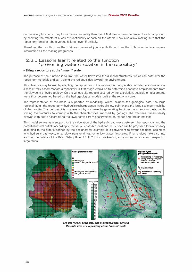
on the safety functions. They focus more completely than the SEN alone on the importance of each componentby showing the effects of a loss of functionality of each on the others. They also allow making sure that therepository remains robust versus failures, even if unlikely.
Therefore, the results from the SEA are presented jointly with those from the SEN in order to completeinformation as the reading progresses.
2.3.1 Lessons learnt related to the function "preventing water circulation in the repository"
• Siting a repository at the "massif" scale
The purpose of the function is to limit the water flows into the disposal structures, which can both alter therepository materials and carry along the radionuclides toward the environment.
This objective may be met by adapting the repository to the various fracturing scales. In order to estimate howa massif may accommodate a repository, a first stage would be to determine adequate emplacements fromthe viewpoint of hydrogeology. On the various site models covered by the calculation, possible emplacementswere thus determined based on the hydrogeological models built at the regional scale.
The representation of the mass is supported by modelling, which includes the geological data, the largeregional faults, the topography (hydraulic recharge zones, hydraulic low points) and the large-scale permeabilityof the granite. This permeability is assessed by software by generating fractures on a random basis, whileforcing the fractures to comply with the characteristics imposed by geology. The fractures transmissivityevolves with depth according to the laws derived from observations on French and foreign massifs.
This model serves as a support for the calculation of the hydraulic pathways between the repository and thepotential natural outlets according to the various possible locations. Thus, sites can be proposed for a repositoryaccording to the criteria defined by the designer: for example, it is convenient to favour positions leading tolong hydraulic pathways, or to slow transfer times, or to low water flow-rates. Final choices take also intoaccount the criteria of the Basic Safety Rule RFS III.2.f, such as keeping a minimum distance with respect tolarge faults.
M1 site model: geological and hydrogeological context
Possible sites of a repository at the "massif" scale
136
ANDRA > Assets of granite formations for deep geological disposal. Dossier 2005 Granite
95467_Chap5_GRANITE.qxp 11/04/07 14:44 Page 136

5
137
In the example of the M1 site model, the calculations performed show that the hydraulic pathways can havedistances significantly different from one position to another, or according to the pathways choices (from 500metres for the shortest one to more than 10 km for the longest one). The "repository siting" within the massifallows favouring long hydraulic pathways and low flow rates. On account of this, two sites were adopted forthe calculations.
These techniques could be implemented to identify a zone of interest for a repository within a massif.
• Siting the repository modules
During the construction of a repository in a granite massif, the reconnaissance approach consists of determiningthe positioning of the repository modules. With this approach, the positioning of the repository modules and thedisposal cells is set during the repository construction work based on a precise characterisation of the locations.In the generic calculations performed, the positioning of the repository modules cannot be optimised as it wouldbe within a complete reconnaissance approach of a site. A statistical adjustment was made based on theextension of the fractures using the fractures network model (DFN): for the B waste, the maximum dimensionfor a fracture intercepted by the disposal tunnels is by convention 80 m, and for the C waste, the maximumdimension is 300 m. This approach is indeed a penalising one close to a characterisation defect situation for somecalculations (particularly for C waste) because, in a real situation, the repository would be progressively adaptedso as to get the best out of the available sound granite blocks. The results shown below are, therefore, to beweighted due to the fact that repository module locations randomly distributed are not affected by such anoptimisation. The analysis is, nonetheless, a good indicator of the issues which would underlie the characterisationand reconnaissance work of a site before and during disposal.
• Transport regime within the repository structures
An indicator which gives a good idea of the hydraulic system within the repository’s structures is thedimensionless Péclet number, which is the ratio between the diffusion and convection times. For small values(and, in particular, less than 1), the hydraulic regime is dominated by diffusion. This indicator gives the ratiobetween advection and diffusion, but does not allow appraising absolutely the velocity at which each transporttype takes place. To do this, the Darcy velocities (allowing to appraise the flow-rate at which the water transferstake place) can give an idea on the water flow-rates.
In the drifts, the transfer system is essentially determined by the permeability of the backfills, the transmissivityof the fractures in the granite at the wall and the gradient. It seems possible to obtain a diffusion system in therepository drifts (table below), but this depends on the backfill permeability. An incorrect backfill emplacementdegrading the backfill permeability by an order of magnitude (10-9 m/s instead of 10-10 m/s) over a drift sectionhardly affects the transfer regime. However, should the backfill permeability be more heavily degraded (around10-8 m/s), the hydraulic regime within the repository may be affected. The emplacement of such a backfillconstitutes, therefore, a useful design arrangement, but whose performances would have to be definedaccording to the hydraulic regime on a given site.
Definition of the Péclet number
Pe = (Td/Tc) where:
Td = L2ω/DeTc = Lω/(K.gradH).
and: Td, the characteristic migration time by diffusion [year],Tc, the characteristic migration time by advection [year],L, the migration distance [m],ω, the total porosity in the drift backfill [-],De, the effective diffusion coefficient in the backfill [m2/year],K, the backfill permeability [m/year],GradH, the hydraulic head gradient [m/m] in the drift, derived from simulations in homogeneous medium.
Long-term safetyANDRA > Assets of granite formations for deep geological disposal. Dossier 2005 Granite
95467_Chap5_GRANITE.qxp 11/04/07 14:44 Page 137

Estimation of the Péclet number in the backfilled drifts ("equivalent porous medium" approach)
• Robustness of the function "preventing water circulation"
It is important to check whether the performances of the function "preventing water circulation" are robustagainst a failure, regardless of its nature.
The altered scenario "defective sealing and plugs of disposal cells" envisions a situation consisting of notinterrupting over approximately a thickness of 5 centimetres the continuity of the damaged zone of the granitein the wall of the horizontal structures. It focuses on the role of the backfills which have an effectiveness suchthat the sealing defect does not significantly alter the hydraulic transfer regime in the drifts. In a genericcontext, it is hard to distinguish the role of the seals from that of the backfills. It should be noted that forpositioning a repository in a given massif the sound blocks would be first reserved for siting the disposal cells;on the other hand, the connecting drifts may intercept water conducting zones at the edge of these blocks. In such a configuration, sealing the drift on either side of the intercepted fracture could mean a more effectivearrangement than backfill alone. In any case, within the framework of a real site configuration, it would bepossible to favour either the seals or the backfill according to the objective sought, and to distinguish the roleof each more clearly than in the generic configuration.
2.3.2 Lessons learnt related to the function "limiting the release ofradionuclides and immobilising them in the repository"
This function covers all the physico-chemical phenomena which tend to prevent the dissolving of theradionuclides. It involves:
- the flow conditions in the disposal cells, which favour waste durability;
- the leak-tightness of the metallic containers, which isolate the radionuclides from the water;
- and the chemical conditions, which favour the insolubility of the chemical elements.
• Transport in the disposal cells
The function "limiting the release of radionuclides and immobilising them in the repository" depends onthe setup of a diffusive system within the disposal cells, particularly for vitrified waste, which is the mostsensitive waste in terms of the transport conditions in its neighbourhood. From this viewpoint, theindicators such as the Péclet number in the disposal cell are not directly performance indicators of thefunction, but allow determining whether this function can act under favourable conditions. The diffusiveconditions within the disposal cells and low renewal rate of water allow to use, with greater confidence,release models leading to slow flow-rates.
138
ANDRA > Assets of granite formations for deep geological disposal. Dossier 2005 Granite
Near-field granite Backfilled drift
Hydraulicconductivity
(m/s)
Hydraulichead gradient
(m/m)
Hydraulicconductivity
(m/s)
Péclet number(Pe=Td/Tc)
Drift transferregime
B2 waste
(calculation madein 54 m of
connecting driftbetween two
seals)
C2 waste
(calculation madein 15 m of
handling driftbetween the edgedisposal cell and
the seal)
10-11 10-3
10-11 10-2
10-10 10-2
10-11 10-3
10-11 10-2
10-10 10-2
10-10
10-9
10-8
10-10
10-9
10-8
10-10
10-9
10-8
10-10
10-9
10-8
10-10
10-9
10-8
10-10
10-9
10-8
0,0390,160,390,391,63,9
0,493,814
0,0120,0991,10,111,112
0,131,110
diffusivediffusivediffusivediffusive
mixed diff/advadvectivediffusiveadvectiveadvectivediffusivediffusive
mixed diff/advdiffusive
mixed diff/advadvectivediffusive
mixed diff/advadvective
95467_Chap5_GRANITE.qxp 11/04/07 14:44 Page 138

139
In the disposal cells containing C waste and spent fuel, the Péclet number shows that the system isdiffusive in all the cases (table below). The most influential parameters which contribute to maintainingthis regime are, on the one hand, the presence of the buffer engineered barrier, and, on the other hand,the transmissivity of small fractures on the periphery of the disposal cell. The "dead end" architecture ofthe disposal tunnels also helps limiting quantities of water ingress.
Estimation of the Péclet number in the bentonite of the C2 waste disposal cells,
("equivalent porous medium" approach)
With respect to the calculations in the equivalent porous medium, which do not allow discriminating thedisposal cells from one another, the calculations in the fractures network model (DFN) reveal that even if theregime remains diffusive inside the disposal cell for all possible cases, the situations can be locally contrastedaccording to the fractures intercepted by the disposal cells.
Modelling the transfers in a C waste disposal cell (DFN approach in granite)
Long-term safetyANDRA > Assets of granite formations for deep geological disposal. Dossier 2005 Granite
Near-field granite Bentonite engineered barrier (bentonite EB)
Hydraulicconductivity
(m/s)
Hydraulic head gradient
imposed (m/m)
Hydraulic headgradient induced
(m/m)
Péclet number(anion) (Pe=Td/Tc)
Transfer regime in the bentonite EB
Horizontalgradient
(calculation madewith 0,60 m ofbentonite in theradial direction)
Estimation ofthe Péclet
number in thebentonite EB
(C2 waste)
Vertical gradient
(calculation madewith 5,30 m ofbentonite in thevertical direction)
10-11 10-3
10-10 10-2
10-11 10-3
1,1x10⁻³
2,2x10⁻²
1,1x10⁻³
~0,0004
~0,008
~0,003
diffusive
diffusive
diffusive
10-10 10-2 1,1x10⁻² ~0,033 diffusive
5
95467_Chap5_GRANITE.qxp 11/04/07 14:44 Page 139
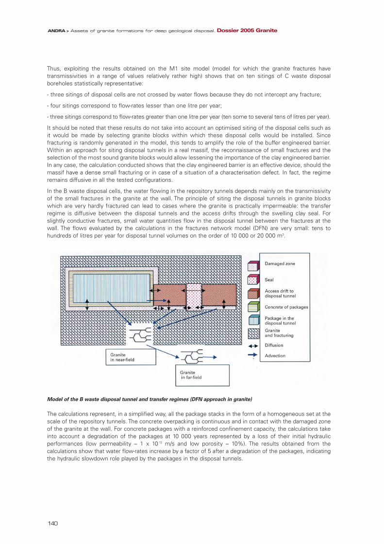
Thus, exploiting the results obtained on the M1 site model (model for which the granite fractures havetransmissivities in a range of values relatively rather high) shows that on ten sitings of C waste disposalboreholes statistically representative:
- three sitings of disposal cells are not crossed by water flows because they do not intercept any fracture;
- four sitings correspond to flow-rates lesser than one litre per year;
- three sitings correspond to flow-rates greater than one litre per year (ten some to several tens of litres per year).
It should be noted that these results do not take into account an optimised siting of the disposal cells such asit would be made by selecting granite blocks within which these disposal cells would be installed. Sincefracturing is randomly generated in the model, this tends to amplify the role of the buffer engineered barrier.Within an approach for siting disposal tunnels in a real massif, the reconnaissance of small fractures and theselection of the most sound granite blocks would allow lessening the importance of the clay engineered barrier.In any case, the calculation conducted shows that the clay engineered barrier is an effective device, should themassif have a dense small fracturing or in case of a situation of a characterisation defect. In fact, the regimeremains diffusive in all the tested configurations.
In the B waste disposal cells, the water flowing in the repository tunnels depends mainly on the transmissivityof the small fractures in the granite at the wall. The principle of siting the disposal tunnels in granite blockswhich are very hardly fractured can lead to cases where the granite is practically impermeable: the transferregime is diffusive between the disposal tunnels and the access drifts through the swelling clay seal. Forslightly conductive fractures, small water quantities flow in the disposal tunnel between the fractures at thewall. The flows evaluated by the calculations in the fractures network model (DFN) are very small: tens tohundreds of litres per year for disposal tunnel volumes on the order of 10 000 or 20 000 m3.
Model of the B waste disposal tunnel and transfer regimes (DFN approach in granite)
The calculations represent, in a simplified way, all the package stacks in the form of a homogeneous set at thescale of the repository tunnels. The concrete overpacking is continuous and in contact with the damaged zoneof the granite at the wall. For concrete packages with a reinforced confinement capacity, the calculations takeinto account a degradation of the packages at 10 000 years represented by a loss of their initial hydraulicperformances (low permeability – 1 x 10-13 m/s and low porosity – 10%). The results obtained from thecalculations show that water flow-rates increase by a factor of 5 after a degradation of the packages, indicatingthe hydraulic slowdown role played by the packages in the disposal tunnels.
140
ANDRA > Assets of granite formations for deep geological disposal. Dossier 2005 Granite
95467_Chap5_GRANITE.qxp 11/04/07 14:44 Page 140

5
141
B5.2 waste disposal tunnels Before 10 000 years After 10 000 years
Water flow-rate in the tunnels 30 l/year 150 l/year
Comparison of water flow-rates in B5.2 waste disposal tunnels before and after 10 000 years
(DFN calculations for the M1 site model – case of a granite characterised with small, slightly conducting fracturing)
• Role of the containers
Another aspect of the function "limiting the release of radionuclides and immobilising them in the repository" isthe leak-tightness provided by the metallic containers. Initial analyses conducted on the performance calculationsenvision both high-performance containers and defective containers (a limited number in the normal evolutionscenario, a greater series in the altered evolution scenario). The comparison of both situations provides a firstappraisal of the interest of this device.
For spent fuel, the copper container has a sufficient durability over the safety demonstration period so that thereis no release in the normal situation. In the package defect situation with the water arrival on the assemblies afterapproximately a century, the releases take place as the matrix dissolves. This dissolution extends over severalthousands of years (approximately 5 000 years) if a conservative radiolytic dissolution model is used. With a"classical" dissolution model such as internationally adopted, releases take place over a period up to over a millionyears. However, in case of a CU container failure, the released radionuclides do not immediately migrate out fromthe disposal cell, because they are stopped or slowed down by the buffer engineered barrier.
For C waste, the analysis compares two illustrative cases: the case of a repository module in which the overpacks"normally" lose their leak-tightness after 1 000 years and the case of a repository module in which a fraction of theoverpacks (5%) are defective after approximately one century. The calculations show in the case of a fraction ofdefective packages a faster migration of radionuclides out of the granite near field for a period of a few thousandyears. Beyond, the molar flux is similar in both treated cases.
It should also be noted that in a generic context and considering the data available it was not possible to explicitlyrepresent the effect which temperatures significantly higher than natural temperatures (as temperatures whichthe radionuclides released by the defective containers could face) would have on the transport parameters. Sucheffects, when accounted for, could highlight better the role of the metallic overpacks for C waste.
To conclude, in the context of calculations carried out on generic models, where the distribution of the disposalboreholes is only partially adjusted to fracturing, the durable containers constitute a useful barrier to compensatefor the geological medium. In particular, the durable copper container for spent fuel offers an appropriate optionat this stage with respect to the adaptation to fracturing. Similarly, the overpack for C waste allows managing theuncertainties linked to the transport of radionuclides in a thermal environment. In a generic context, the containersconstitute in any case a cautious design provision providing a complementarity with respect to the bufferengineered barriers and the geological medium.
• Precipitation in the disposal cells
The function "limiting the release of radionuclides and immobilising them in the repository" is also evidencedby a limited dissolving of the radionuclides. The calculations allow, indirectly, measuring the effects of thisfunction by identifying the radionuclides whose migration is restricted by a solubility limit reached in the nearfield. Considering the concepts proposed by Andra, the sorption of the elements by the swelling clay (for theradionuclides coming from the C waste or spent fuel disposal cells) and in the concrete (for the B waste) isgenerally the factor limiting the migration of most of the radionuclides. For some radionuclides which areslightly sorbed, the solubility limit controls, however, the transfer. This is particularly true for selenium, whoseflux is attenuated by several orders of magnitude when solubility is taken into account.
Long-term safetyANDRA > Assets of granite formations for deep geological disposal. Dossier 2005 Granite
95467_Chap5_GRANITE.qxp 11/04/07 14:44 Page 141

Limitation of molar flux by solubility – Example of selenium for a C2 waste module
(M1 site model – DFN approach
2.3.3 Information related to the function "delaying and reducing radionuclides migration"
This function performances are shown by attenuation indicator (ratio between the mass of radionuclides exitinga compartment of the repository and the mass of radionuclides entering it; ratio between the maximum fluxof radionuclides exiting a compartment and the maximum flux of radionuclides entering it) and the delayindicator (difference between the time of occurrence of the maximum flux out of a compartment and into acompartment). These indicators can be assessed at various locations:
- when exiting from the B waste disposal cells, they allow evaluating, by comparing them with the "release bywaste" chronicle, the interest of attributing the hydraulic performances to the B waste packaging, particularlyby comparing the case where these packages have hydraulic performances with the case where thesepackages have only chemical performances associated with a degraded concrete;
- when exiting from the clay buffer engineered barriers of the C waste and spent fuel disposal cells, they allowevaluating what these clay elements bring, particularly with respect to the contribution from the hostformation;
- when exiting from the near field in the granite massif, they allow evaluating the performances of the smallfracturing and the determining factors of these performances;
- when exiting the far field in the granite massif, they allow evaluating the global attenuation capacity of themassif and the transfer times within it, as well as the characteristics which most influence theseperformances.
• Delay and attenuation in the disposal cells
The function performances in the disposal cell are directly related to the model parameters: the sorption inconcrete (for the B waste disposal tunnels) and in swelling clay (for the other disposal cells).
For B waste, a useful example of the role played by the concrete container, already seen above in the role itplayed in the protection of the waste against water flows, is to compare the releases in the near field betweena non-degraded concrete container with hydraulic performances and a container having only chemicalperformances associated with a degraded concrete. The calculations carried out in an equivalent porousmedium indicate that the container’s role is more evident when the granite at the wall of the disposal cells ismore fractured. In all cases (standard container or container with reinforced confinement), the calculations inthe fractures network model (DFN) show that the B waste concrete overpacking has a straightforward effect
142
ANDRA > Assets of granite formations for deep geological disposal. Dossier 2005 Granite
Se79 m
ola
r fl
ux [
Mo
l/year]
95467_Chap5_GRANITE.qxp 11/04/07 14:44 Page 142

5
143
on the retention of radionuclides very strongly sorbed in concrete (such as actinides) or more weakly sorbedlike selenium 79.
For C waste and spent fuel disposal cells, the delay and attenuation performances of the disposal cells are lessdependent on local fracturing due to the presence of the bentonite engineered barrier. The unsorbed radionu-clides will diffuse through this barrier and migrate outside the disposal cell in a million years. The radionuclidessorbed by the bentonite such as actinides, tin-126 or to a lesser extent caesium-135 are significantly delayedin their migration. Thus, for caesium-135, the calculations related to the scenario of a defective spent fuelcontainer show that the percentage of mass migrating outside the disposal cell through the clay engineeredbarrier is only approximately 8% after 100,000 years and 16% after one million years with respect to their initialmass (DFN calculations – M1 site model).
• Delay and attenuation in granite
Several parameters intervene to slow down the migration of radionuclides in the granite’s fractures andattenuate the flux:
- the hydraulic properties of the fractures and their connectivity;
- the retention (sorption) properties of the fractures and the granite rock at the fractures plane;
- the topographical and morpho-structural arrangement of the granite masses for the far field.
As a result, the radionuclides are classified into two major categories:
- the unsorbed elements (iodine 129, chlorine 36, etc.). Their transfer time through the fractures is the directreflection of the length of the hydraulic pathway leading to the surface. For these radionuclides, the function"delaying and reducing the migration" is practically the same as the function "preventing water circulation".Their migration is essentially imposed by the topographical and morpho-structural arrangement of the massif– which controls the gradient and the length of the pathways – as well as the transmissivity and connectivityof the fractures;
- the elements sensitive to sorption at the fracture planes, which can be significantly delayed; sorption can thengive them the time to significantly decay in the fractures planes, starting in the near field would the radioactivehalf-life be sufficiently short. It causes a spread of the signal emitted by the repository and, therefore, areduction of the maximum mass flux between the entry in and exit from the massif.
1) Delay and attenuation in the near-field granite: influence of the hydraulic properties of fractures
The site models represent different fracturing configurations representative of geological configurations in theFrench context. The fractures transmissivity in the M2 site model is lower because they are clogged byhydrothermal minerals than the one in the M1 and M3 site models. For the generic studies, the intersectionsbetween the transmissive fractures are assumed to be systematically water conductive, which is penalising formany granite massif configurations. However, comparing the migration flux calculations of mobile radionuclidessuch as iodine 129 between the M1 and M2 site models shows the major influence of the hydraulic propertiesof the near-field fractures.
The case of B waste is easy to illustrate because there are few disposal tunnels and they are sited in almostunfractured granite blocks. Calculations are carried out for the most penalizing pathway of iodine 129 betweenthe disposal tunnel and the model boundaries.
Long-term safetyANDRA > Assets of granite formations for deep geological disposal. Dossier 2005 Granite
95467_Chap5_GRANITE.qxp 11/04/07 14:44 Page 143

Migration of iodine 129 in the M1 and M2 site models – Molar flux for a B2 waste disposal cell (DFN approach)
For a granite in which the fractures have very low transmissivity in the near field (M2 site model), the maximumflux is reduced and iodine remains in the near-field granite over several hundreds of thousands of years. For granite in which the fractures are more transmissive (M1 site model), flux is higher and the total inventoryof iodine 129 reaches the model boundaries after a hundred thousand years or so.
For C waste and spent fuel, a variation in the fractures transmissivity on repository performances, like for Bwaste, causes changes in the flux and migration times of the radionuclides. On account of the multiplicity ofthe radionuclide pathways corresponding to the various disposal cells in a module, the global situation isconsequentially smoothed by the pathways variability. Thus, the influence of the fractures hydraulic parametersmust also be examined with the other properties of the granite, particularly their geometric organisation, whichdetermines the pathways. Sensitivity to the fractures transmissivity can be illustrated by the assessment ofthe model outgoing flux for the transmissivity values varying by one order of magnitude for all the fractures.
144
ANDRA > Assets of granite formations for deep geological disposal. Dossier 2005 Granite
Mo
lar
flu
x [
Mo
/year]
95467_Chap5_GRANITE.qxp 11/04/07 14:44 Page 144
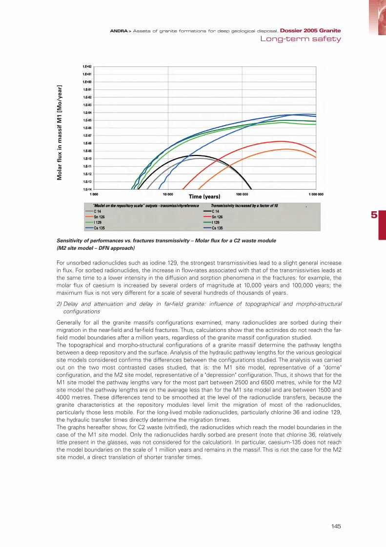
5
145
Sensitivity of performances vs. fractures transmissivity – Molar flux for a C2 waste module
(M2 site model – DFN approach)
For unsorbed radionuclides such as iodine 129, the strongest transmissivities lead to a slight general increasein flux. For sorbed radionuclides, the increase in flow-rates associated with that of the transmissivities leads atthe same time to a lower intensity in the diffusion and sorption phenomena in the fractures: for example, themolar flux of caesium is increased by several orders of magnitude at 10,000 years and 100,000 years; themaximum flux is not very different for a scale of several hundreds of thousands of years.
2) Delay and attenuation and delay in far-field granite: influence of topographical and morpho-structuralconfigurations
Generally for all the granite massifs configurations examined, many radionuclides are sorbed during theirmigration in the near-field and far-field fractures. Thus, calculations show that the actinides do not reach the far-field model boundaries after a million years, regardless of the granite massif configuration studied. The topographical and morpho-structural configurations of a granite massif determine the pathway lengthsbetween a deep repository and the surface. Analysis of the hydraulic pathway lengths for the various geologicalsite models considered confirms the differences between the configurations studied. The analysis was carriedout on the two most contrasted cases studied, that is: the M1 site model, representative of a "dome"configuration, and the M2 site model, representative of a "depression" configuration. Thus, it shows that for theM1 site model the pathway lengths vary for the most part between 2500 and 6500 metres, while for the M2site model the pathway lengths are on the average less than for the M1 site model and are between 1500 and4000 metres. These differences tend to be smoothed at the level of the radionuclide transfers, because thegranite characteristics at the repository modules level limit the migration of most of the radionuclides,particularly those less mobile. For the long-lived mobile radionuclides, particularly chlorine 36 and iodine 129,the hydraulic transfer times directly determine the migration times.The graphs hereafter show, for C2 waste (vitrified), the radionuclides which reach the model boundaries in thecase of the M1 site model. Only the radionuclides hardly sorbed are present (note that chlorine 36, relativelylittle present in the glasses, was not considered for the calculation). In particular, caesium-135 does not reachthe model boundaries on the scale of 1 million years and remains in the massif. This is not the case for the M2site model, a direct translation of shorter transfer times.
Long-term safetyANDRA > Assets of granite formations for deep geological disposal. Dossier 2005 Granite
Mo
lar
flu
x i
n m
assif
M1 [
Mo
/year]
95467_Chap5_GRANITE.qxp 11/04/07 14:44 Page 145

Attenuation of the radionuclide flux for M1 and M2 site models – Molar flux for a C2 waste module (DFN approach)
• Repository robustness to a possible characterisation error
The altered "characterisation defect" scenario allows showing the importance of a more or less detailedfracturing characterisation. The adaptation of repository architecture to granite fracturing is subject toreconnaissance operations prior to the various site reconnaissance stages. A particularly important stage is thecharacterisation of the fracturing carried out, in situ, in the repository before excavating the disposal cells andemplacing the packages.The consequences of a characterisation defect can be analysed by comparing a normal evolution scenario inwhich this characterisation is correctly carried out to a "characterisation defect" scenario which considers thenon identification of fractures which should have been avoided. For C waste, 10% of the possible positions of the disposal cells were excluded for the normal evolutionscenario: these positions correspond to the most unfavourable near-field hydraulic conditions. On the otherhand, for the characterisation defect scenario, all the possible positions for the disposal cells are considered. The radionuclide transfers for the C2 module are calculated in both cases by distributing the correspondinginventory on the possible pathways coming from the disposal cells (10% of disposal cells positions rejected inthe normal case and none rejected in the characterisation defect case). The comparison in terms of molar fluxis given in the figure below. For caesium-135, the 10% of disposal cell positions not rejected corresponding to the most penalisingsituations hydraulically lead to a maximum molar flux increased by a factor of 5 (after 400,000 years). The molarflux is increased by approximately two orders of magnitude at 10,000 years and by approximately one order ofmagnitude at 100,000 years. This underlines the importance of the characterisation and its influence on thesystem’s overall performance. On a particular site, it would be advisable to specify earlier the effect of a sortingof positions of the disposal cells.
146
ANDRA > Assets of granite formations for deep geological disposal. Dossier 2005 Granite
Mo
lar
flu
x i
n m
assif
M1 [
Mo
/year]
Mo
lar
flu
x i
n m
assif
M2 [
Mo
l/year]
95467_Chap5_GRANITE.qxp 11/04/07 14:44 Page 146

5
147
Comparison of molar flux with and without a 10% rejection rate of the disposal cells – Molar flux in caesium-135 of a
C2 waste module in an M2 massif (DFN approach)
For B waste, and particularly B5.2 waste, the impact of a bad local characterisation would be relatively moresensitive in terms of quantities of radionuclides released than for C waste. This is due to the larger number ofpackages potentially concerned. A local characterisation defect of the small fracturing concerned by the installationof a disposal tunnel would not jeopardise the global performances of a B5.2 waste repository. In fact, the charac-terisation defect would only be considered sensitive in case of a large characterisation error, meaning that thedisposal tunnels intercept a great extension (multi-hectometres) and significantly transmissive fracture, which isnot realistic considering the proposed reconnaissance strategy and the small number of tunnels to be installed. All in all, although the fracturing characterisation and the adaptation of the repository according to its hydraulic andtransport characteristics appear important, the repository is, globally speaking, hardly sensitive to a local error. Infact, because of the fractioning (modules, disposal cells), a characterisation error would only affect a moderatepart of the emplaced packages inventory.
2.4 Conclusion of the calculationsIn a generic context, the calculations carried out cannot pretend to be conclusive either in the achievement ofthe safety objectives or in the performances of the safety functions of each component. Nonetheless, thecalculations provide a wealth of important information from a methodological viewpoint as well as from theviewpoint of key determining factors, which condition the repository’s safety.From a methods viewpoint, the use of computational tools both "classical" (such as those carried out in ahomogeneous medium) and more "specific for granite" (those carried out in a fractured medium) underline thecomplementarity of both approaches. The first kinds of tools ("classical" calculations) allow determining in astraightforward fashion the influence of the main macroscopic parameters: hydraulic gradient, large-scalepermeability of the rock and the structures, Péclet number, etc. The second kinds of tools (calculations in thefractured medium) allow accessing more versatile information, connecting near-field performances to thestructuring and distribution of small fracturing, or setting up a relationship between medium-scale fracturingand large-scale permeability. This information would have to be exploited under the assumption of a sitereconnaissance in order to progressively determine from safety analyses the relevant criteria for the repositorysiting and architecture. The reconnaissance of fracturing and the correct characterisation of its hydraulic properties prove to beimportant for controlling flows in and around the repository. At the repository modules scale, they lead topositions protected from moderate fracturing, where it is too water conductive. At the disposal cells scale, the
Long-term safetyANDRA > Assets of granite formations for deep geological disposal. Dossier 2005 Granite
CS
135
mo
lar
flu
x [
Mo
l/year]
95467_Chap5_GRANITE.qxp 11/04/07 14:44 Page 147

adaptation of the position of the disposal cells to small fracturing provides an additional opportunity to limit theflows and to favour long radionuclide pathways. Nonetheless, due to their large-scale fractioning, the repositorymodules of vitrified waste and spent fuel prove to be hardly sensitive to local characterisation defects. On theother hand, the B waste disposal tunnels because of their larger size may be more sensitive to the quality ofthe granite block in which they would be sited; a characterisation defect may affect the repository performanceif a fracture of large extension and significant transmissivity is not detected. This case seems to be highlyunlikely within the reconnaissance approach proposed for characterising a granite massif and considering thelimited number of disposal tunnels.
From the viewpoint of results, the calculations carried out on a generic site show the good complementaritybetween the properties of the engineered structures and those of the geological medium. In the current stateof knowledge, backfill performances prove to be significant for controlling flows within the repository, providedthe site itself provides a controlled permeability and low gradients. The clay buffer engineered barriers ensurea diffusive system in the disposal cells and immobilise the hardly soluble radionuclides. The B waste concretecontainers participate in both water flow limitation and radionuclides sorption. The C waste overpacks delayradionuclides release in the disposal cells. The spent fuel copper containers allow a durable confinement of theradioactivity and offer flexibility at this generic studies stage with respect to the repository siting and thefracturing. Retention in the granite fractures allows greatly limiting the flux of radionuclides subjected tosorption and, in favourable configurations, preventing their transfer to the model boundaries.
Although safety analyses - both qualitative analysis and calculations – are conducted on generic site models,with all the reservations attached to this type of exercise, they do not identify elements which would rule outthe granite medium for a high level and long lived waste repository.
148
ANDRA > Assets of granite formations for deep geological disposal. Dossier 2005 Granite
95467_Chap5_GRANITE.qxp 11/04/07 14:44 Page 148
5
149
Long-term safetyANDRA > Assets of granite formations for deep geological disposal. Dossier 2005 Granite
95467_Chap5_GRANITE.qxp 11/04/07 14:44 Page 149

150
ANDRA > Assets of granite formations for deep geological disposal. Dossier 2005 Granite
ConclusionThe Act of 30 December 1991 initiated a process of research into different methods for managing high-level,long-lived waste. In this context, Andra conducted work to study the possibility of a repository in a deepgeological formation, examining two rocks of different nature: clay and granite. For granite medium, with nodesignated site, the purpose of the research programme was to assess the interest of the rock for a deeprepository. With this aim, various issues concerning disposal in granite medium were addressed. Generic options for a repository were proposed in response to the applicable safety objectives
1. A generic study initiative on French granitesbacked up by studies and research on graniteconducted abroad
To study the granite medium, Andra began by collecting the body of scientific knowledge available that couldserve as a basis for the study of a geological repository. This concerned both granite mediums encountered inFrance, and also granite mediums studied by counterparts abroad (SKB in Sweden, Posiva in Finland, Nagra inSwitzerland and AECL in Canada). This initiative resulted in a global view of the intrinsic properties of the rockand its potential for a repository.
Firstly Andra capitalised on all the knowledge acquired on French granite, especially through mining feedbackor site work conducted during recent decades. The geological data available for roughly 78 granite areas largerthan 20 km2 spread across France (Massif Central, Armorican Massif) were collected and analysed. This provided an appraisal of the common characteristics and the properties variability of French granites.
In addition, Andra made the most of the French scientific community for major issues relating to the repository,especially for an understanding of the organisation of granite fracturing. This took the form of partnerships withresearch organisations and also a policy of training support for research, through thesis grants.
Foreign laboratories made a very important contribution, both for methodology and in providing scientific results. Andra made an important contribution to experiments in underground laboratories in Canada(Lac du Bonnet laboratory), Switzerland (Grimsel laboratory) and Sweden (Äspö laboratory). This enabled it toconduct experiments in partnership with its counterparts. It led to a comparison of studies and research, andalso provided a thorough understanding of how some of the results obtained in these laboratories could betransposed into the context of French granite. In particular, surveying a granite block and modelling circulationin fractures in the Äspö laboratory backed up the understanding of the phenomena involved. The large majorityof results obtained can be transposed to French granite massifs. Likewise, the sealing test conducted in theLac du Bonnet laboratory demonstrated the possibility of effectively sealing a structure in granite to preventwater circulation. Finally, in a framework of partnership with Posiva, Andra participated in surface-basedsurveying at the Olkiluoto site, enabling it to test and control the various techniques.
The studies and research conducted by Andra are based on a large amount of work conducted abroad ondisposal in a granite medium. In particular, repository design studies conducted by Andra are largely based onknowledge acquired abroad, especially in Sweden and Finland.
95467_Conclusion_GRANITE.qxd 11/04/07 14:48 Page 150

2. A repository in a granite formation is conceivableAssessing the assets of granite for a disposal system means mainly the possibility of surveying andunderstanding the organisation of a granite massif, of studying how a repository could be built in this massif,and of appraising whether this repository could protect man and the environment against the radioactive wasteemplaced therein. All these issues were addressed. The analysis stresses that, at this stage, there is no basicobstacle ruling out this possibility.
• Methods exist for surveying and characterising granite.
Work conducted in foreign laboratories or surface-based work at various sites led to successful testing ofvarious granite characterisation and modelling methods which will be required to survey a site.
Methods exist for surveying a granite massif. Associated with modern modelling tools, these methods provide,a priori, an understanding of its organisation (arrangement of granite blocks, structuring of fractures, etc.) andits functioning in terms of underground water circulation.
• Generic architectures are proposed for a reversible disposal system in a granite medium.
Repository architecture must be adapted to the characteristics of the geological medium. Generally, soundgranite is characterised by high mechanical strength and very low permeability. It is also a medium containingvery little underground water. The proposed generic concepts harness these properties common to all granitesand also take into account the specific features of granites in the French geological context.
However, fractures of the deep granite medium may allow slow circulation of water. The concepts proposedavoid this as far as possible by architectural adjustment to the various scales of fracturing: the disposal zonesare located away from the main faults in the granite massif and the disposal cells are positioned in sound rockof very low permeability so that they only intercept fractures with little or no conductivity. In addition, thedesign allows for installation of low-permeability sealing and backfill which protect the disposal cells from theslow water movement that could occur.
Repository design also includes design of waste packages for each type of waste (B or C waste) or spent fuel.Overpacking options are proposed for B waste packages (concrete) or C waste packages (steel). These aresimilar to the ones designed for clay medium, with, however, the use of an enhanced confinement propertiescontainer for certain types of B waste. For spent fuel, if not reprocessed, the advantage of copper containersdeveloped in Sweden and Finland and achieving very long duration confinement was examined.
Repository architectures proposed for granite are adapted to the fracturing of the medium and take advantageof the very low permeability and high strength of the sound rock. The rock properties are backed up byengineered structures ensuring confinement of radioactivity: overpacking primary waste packages incontainers, sealing and backfilling the structures. In addition, many studies conducted for the clay medium casecan be transposed when concerning operational and occupational safety, demonstrating the possibility of a safeoperation without environmental impact, on the basis of feedback from other mining or nuclear facilities.
• Reversibility at the heart of the study approach and expressed in concrete practical terms
The generic architectures proposed for the repository were selected according to their ability to allow forreversibility under the best possible conditions. Andra has developed a concrete approach to reversible disposalthat is more than just the technological possibility of withdrawing the packages. This approach, quite commonto the clay medium study, may be defined as the possibility for a step-wise, progressive and flexible control ofthe disposal process. The objective is to allow future generations freedom of decision in waste management.In addition, Andra has decided not to set a predetermined duration for reversibility. This involves offering asgreat flexibility as possible in the management of each stage, allowing for the possibility of maintaining thestatus quo before deciding on the next stage or going backward. The repository design (modular architecture,simplified operation, dimensioning and choice of durable materials, etc.) aims at allowing the widest possiblechoices.
The reversible disposal system can thus serve two purposes. It can be managed as a storage facility withemplacement of waste and, if so desired, its retrieval by simple reversal of the disposal process. Obviously,maintaining this reversibility assumes human intervention, without, however, causing excessive workloads. Butwhat essentially distinguishes it from a simple storage process is that it includes the possibility of beingprogressively closed, so as to be able to subsequently evolve safely and passively without human intervention.
ConclusionANDRA > Assets of granite formations for deep geological disposal. Dossier 2005 Granite
151
95467_Conclusion_GRANITE.qxd 11/04/07 14:48 Page 151

152
ANDRA > Assets of granite formations for deep geological disposal. Dossier 2005 Granite
The granite geological medium and the concepts developed by Andra allow to meet the reversibilityrequirement and to turn reversibility into a flexible tool in radioactive waste management. Reversibility alsoenables progressive confidence building in the demonstration of repository safety, always leaving open theeventual possibility of an evolution independent of human intervention.
• Tested repository safety analysis methods.
A reversible disposal system is designed to be closed if this option is taken. It is therefore important to examinethe suitability of the proposed generic architecture for the long-term safety objectives, i.e. its ability to providedurable protection for man and the environment against the waste which would be emplaced in the repository.This examination was conducted using methods proven at international level, especially on the basis of i) asystematic analysis of the various characteristics of the repository and granite, ii) the processes governing itslong-term evolution and iii) the possible events that could disturb it. This analysis is based on all the knowledgeacquired in the field at international level, especially in foreign underground laboratories. In particular, thisknowledge concerns interactions (thermal, hydraulic or chemical) between a repository and granite, as well asthe important issue of radionuclide retention by the fractures.
In addition to a qualitative assessment, simulations have been run to obtain quantitative assessmentinformation. This requires calculation means dedicated to the fractured medium which have been extensivelydeveloped at international level.
In a context of generic studies, this cannot involve repository impact calculations indicating radioactivity dosesto which man and the environment may be exposed. However, quantitative assessments provide anunderstanding of orders of magnitude in terms of the confinement performance of granite and the variousrepository components. They indicate that, while ruling out site configurations not manifestly meeting the BasicSafety Rule RFS III.2.f. criteria of the French Nuclear Safety Authority, the proposed technical solutions wouldmake the most of the favourable properties of granite.
From the methodological point of view, these analyses allow all numeric tools specifically developed for thegranite medium to be tested. The simulations confirm that, assuming a site survey is to be carried out, meansfor assessing repository safety in a granite medium would be available throughout the research process.
The safety analyses carried out on the proposed generic repository architectures underline the availability ofmethods for assessing the long-term safety of a repository in granite: description of repository evolution overtime, understanding and modelling of the phenomena involved and computer tools. Apart from themethodological lessons learnt, safety analyses have underlined the suitability of the proposed options and theabsence, at this stage, of any element ruling out feasibility with respect to the safety objectives.
3. Overall SummaryThe studies conducted by Andra in the context of the Waste Act of 30 December 1991 have been summarisedin a status concerning the assets of the granite medium for a reversible disposal system. The main questionslinked to the specific features of the granite medium have been identified and treated without revealing anyaspects ruling out feasibility. Possible options both for the design of a reversible disposal system and for thesafety approach have been defined at a generic level for granite. The main uncertainty concerns the existenceof sites without a too high fracture density, which would be too demanding on repository architecture.
95467_Conclusion_GRANITE.qxd 11/04/07 14:48 Page 152

NotesANDRA > Assets of granite formations for deep geological disposal. Dossier 2005 Granite
153
95467_Conclusion_GRANITE.qxd 11/04/07 14:48 Page 153

154
ANDRA > Assets of granite formations for deep geological disposal. Dossier 2005 Granite
Notes
95467_Conclusion_GRANITE.qxd 11/04/07 14:48 Page 154

ANDRA > Assets of granite formations for deep geological disposal. Dossier 2005 Granite
155
Notes
95467_Conclusion_GRANITE.qxd 11/04/07 14:48 Page 155

156
ANDRA > Assets of granite formations for deep geological disposal. Dossier 2005 Granite
Notes
95467_Conclusion_GRANITE.qxd 11/04/07 14:48 Page 156

NotesANDRA > Assets of granite formations for deep geological disposal. Dossier 2005 Granite
157
95467_Conclusion_GRANITE.qxd 11/04/07 14:48 Page 157

158
ANDRA > Assets of granite formations for deep geological disposal. Dossier 2005 Granite
Notes
95467_Conclusion_GRANITE.qxd 11/04/07 14:48 Page 158

NotesANDRA > Assets of granite formations for deep geological disposal. Dossier 2005 Granite
159
95467_Conclusion_GRANITE.qxd 11/04/07 14:48 Page 159

Photo credits: ANDRA - SKB - NAGRA - POSIVA - H. PASTEAU - [email protected] - ENRESA
BRGM/S. GENTIER - ANDRA/AECL
95467_Conclusion_GRANITE.qxd 11/04/07 14:48 Page 160

Agence nationale pour la gestion des déchets radioactifs
SYNTHESIS
Assets of granite formations for deep geologicaldisposal
Rep
ort S
erie
s
Do
ssie
r 2
00
5
GRAN
ITE
: SYN
TH
ESIS
- Assets
of gra
nite
form
ations for
deep g
eolo
gical disposal
June 2005
©A
ndra
- 2
67 V
A -
Decem
ber
2006 -
Gra
phic
desig
n:
Media
géra
nce -
IS
SN
: 1
772-2
136
Agence nationale pour la gestion des déchets radioactifs
Parc de la Croix Blanche - 1/7, rue Jean Monnet - F 92298 Châtenay-Malabry Cedex Tél. : 01 46 11 80 00
www.andra.fr
The Andra Publication SeriesEssential SeriesIn a few pages, documents in the Essential Series provide simple and illustrated explanations with a view to furtheringknowledge on radioactive waste and Andra.
Reference SeriesWith standard information concerning Andra methods and progress reports on its investigations or activities, theReference Series presents various technical and other information, especially on the location of radioactive waste.
Periodical SeriesOn a regular basis, Andra publishes various brochures relating to the environmental monitoring of its disposal and research facilities. The Periodical Series includes those publications as well as the respective news bulletins of each site.
Discovery SeriesVideos, CD-ROMs, synthesis images and comic strips… are worth more than a thousand words. The Discovery Seriesuses vivid illustrations to explain to a broad public the underlying principles of radioactive-waste management.
Science and Technology SeriesTaking stock of current knowledge, presenting ongoing research as well as the Agency's methods and approachesconstitute the objectives of the Science and Technology Series. Intented for a specialised public, it provides varioussyntheses and monographs published under the aegis of Andra or in partnership with other scientific organisations.
Report SeriesSummaries, reports and seminar proceedings published in the Report Series highlight the advances of Andra's
ongoing investigations.
Industrial Practices SeriesThe Industrial Practices Series includes documents dealing with the acceptance criteria and the management ofradioactive waste.
95467_COUV Synthèse_Granite 6/04/07 18:23 Page 1


