12 AST4763 Crankshaft Locking Pin-- AST4760B-84 Case + Insert
4760B.011/5
IMPORTANT: Always refer to the vehicle manufacturer’s service instructions, or proprietary manual, to establish the current procedures and data. Product Information Sets detail applications and use of the tools with any general instructions provided as a guide only.
1.5 dci engines (K9K)The K9K series of 1.5dCi engines require Crankshaft Locking Pin AST4562A and Pin AST4360R1 to position the camshaft/sprocket.
As it is necessary to remove the RH engine mounting/bracket when removing and installing the timing belt, the engine must be supported from below.
Remove the upper and lower timing belt covers, fuel pump position sensor and move fuel pipes to one side.
ASt4562A crankshaft locking PinRemove the blanking plug for the crankshaft locking pin from the cylinder block and turn the crankshaft in a clockwise direction so that the camshaft sprocket locking pin hole is just before its alignment position with the timing hole in the cylinder head. This will provide the correct crankshaft position for inserting the AST4562A Crankshaft Locking Pin.
Screw in AST4562A Locking Pin and turn the crankshaft slightly until the “flat” on web of the crankshaft is pressing against the end of the pin.
2/5
1
ASt4360r1 camshaft locking PinInsert AST4360R1 Pin through the timing hole in the camshaft sprocket and into the timing hole in the cylinder head.
NOTE: Some 1.5 K9K engine variants have an adjustable camshaft sprocket (identified by 3 x sprocket retaining bolts to a camshaft carrier plate and elongated timing slot in the sprocket.)
Remove the crankshaft pulley, slacken the belt tensioner and remove belt.
Once a belt has been removed, a new belt and tensioning rollers must be fitted.
Check the positions of timing marks - the camshaft sprocket (positioned by Pin), the crankshaft (keyway vertically upwards) and the fuel pump (approx 1-o-clock position aligned with bolt head directly behind sprocket. Ie. one tooth to right of vertical axis).
NOTE: If the engine variant has an adjustable camshaft sprocket, remove one bolt and slacken the other two by one turn.
Fit the new timing belt, commencing at the crankshaft gear. Ensure that the marks on the belt are aligned with the timing marks on the camshaft, HP pump and crankshaft sprockets. There should be 19 tooth spaces between camshaft and HP pump timing marks and 51 tooth spaces between crankshaft and HP pump marks.
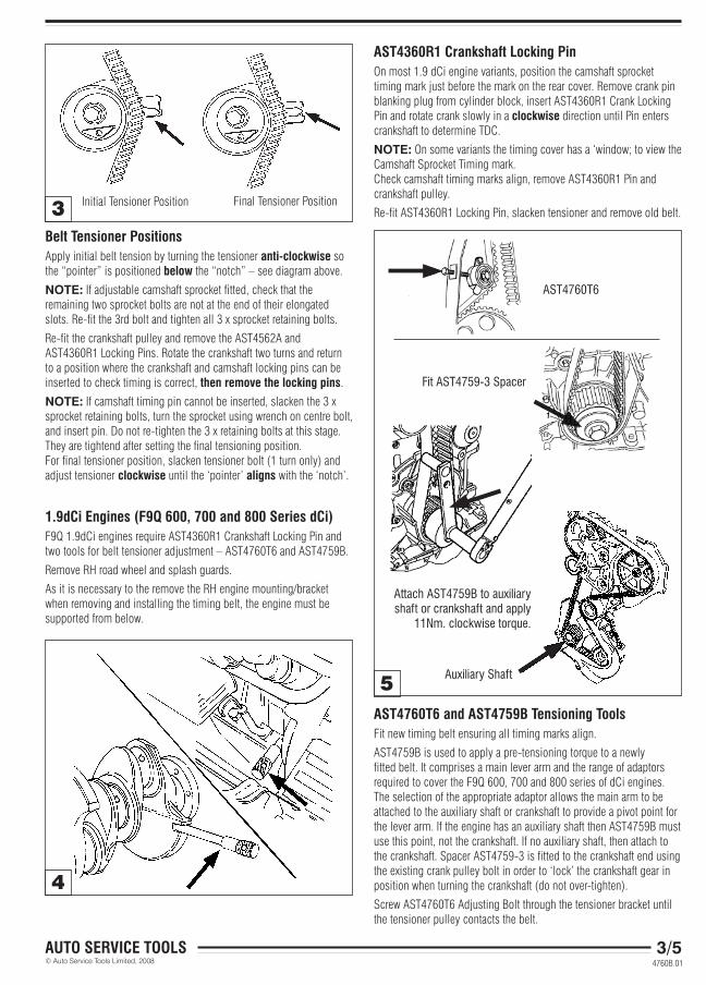
Belt tensioner PositionsApply initial belt tension by turning the tensioner anti-clockwise so the “pointer” is positioned below the “notch” – see diagram above.
NOTE: If adjustable camshaft sprocket fitted, check that the remaining two sprocket bolts are not at the end of their elongated slots. Re-fit the 3rd bolt and tighten all 3 x sprocket retaining bolts.
Re-fit the crankshaft pulley and remove the AST4562A and AST4360R1 Locking Pins. Rotate the crankshaft two turns and return to a position where the crankshaft and camshaft locking pins can be inserted to check timing is correct, then remove the locking pins.
NOTE: If camshaft timing pin cannot be inserted, slacken the 3 x sprocket retaining bolts, turn the sprocket using wrench on centre bolt, and insert pin. Do not re-tighten the 3 x retaining bolts at this stage. They are tightend after setting the final tensioning position. For final tensioner position, slacken tensioner bolt (1 turn only) and adjust tensioner clockwise until the ‘pointer’ aligns with the ‘notch’.
1.9dci engines (F9Q 600, 700 and 800 Series dci)F9Q 1.9dCi engines require AST4360R1 Crankshaft Locking Pin and two tools for belt tensioner adjustment – AST4760T6 and AST4759B.
Remove RH road wheel and splash guards.
As it is necessary to the remove the RH engine mounting/bracket when removing and installing the timing belt, the engine must be supported from below.
3/5
4
5
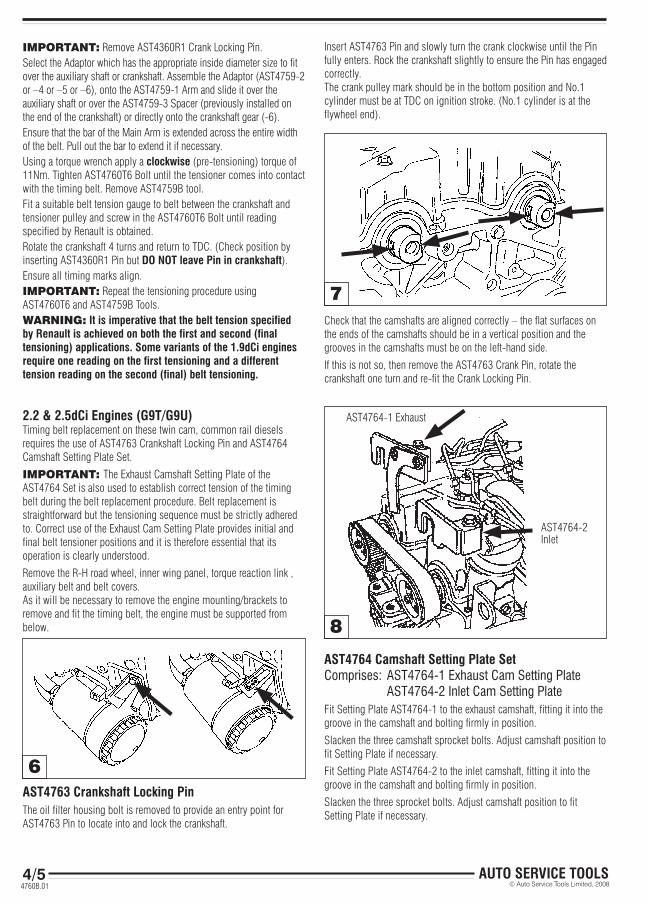
AST4760T6
Fit AST4759-3 Spacer
ASt4760t6 and ASt4759B tensioning toolsFit new timing belt ensuring all timing marks align.
AST4759B is used to apply a pre-tensioning torque to a newly fitted belt. It comprises a main lever arm and the range of adaptors required to cover the F9Q 600, 700 and 800 series of dCi engines. The selection of the appropriate adaptor allows the main arm to be attached to the auxiliary shaft or crankshaft to provide a pivot point for the lever arm. If the engine has an auxiliary shaft then AST4759B must use this point, not the crankshaft. If no auxiliary shaft, then attach to the crankshaft. Spacer AST4759-3 is fitted to the crankshaft end using the existing crank pulley bolt in order to ‘lock’ the crankshaft gear in position when turning the crankshaft (do not over-tighten).
Screw AST4760T6 Adjusting Bolt through the tensioner bracket until the tensioner pulley contacts the belt.
3
ASt4360r1 crankshaft locking PinOn most 1.9 dCi engine variants, position the camshaft sprocket timing mark just before the mark on the rear cover. Remove crank pin blanking plug from cylinder block, insert AST4360R1 Crank Locking Pin and rotate crank slowly in a clockwise direction until Pin enters crankshaft to determine TDC.
NOTE: On some variants the timing cover has a ‘window; to view the Camshaft Sprocket Timing mark. Check camshaft timing marks align, remove AST4360R1 Pin and crankshaft pulley.
Re-fit AST4360R1 Locking Pin, slacken tensioner and remove old belt.Initial Tensioner Position Final Tensioner Position
Attach AST4759B to auxiliary shaft or crankshaft and apply
2.2 & 2.5dci engines (G9t/G9u)Timing belt replacement on these twin cam, common rail diesels requires the use of AST4763 Crankshaft Locking Pin and AST4764 Camshaft Setting Plate Set.
IMPORTANT: The Exhaust Camshaft Setting Plate of the AST4764 Set is also used to establish correct tension of the timing belt during the belt replacement procedure. Belt replacement is straightforward but the tensioning sequence must be strictly adhered to. Correct use of the Exhaust Cam Setting Plate provides initial and final belt tensioner positions and it is therefore essential that its operation is clearly understood.
Remove the R-H road wheel, inner wing panel, torque reaction link , auxiliary belt and belt covers.As it will be necessary to remove the engine mounting/brackets to remove and fit the timing belt, the engine must be supported from below.
ASt4764 camshaft Setting Plate SetComprises: AST4764-1 Exhaust Cam Setting Plate AST4764-2 Inlet Cam Setting PlateFit Setting Plate AST4764-1 to the exhaust camshaft, fitting it into the groove in the camshaft and bolting firmly in position.
Slacken the three camshaft sprocket bolts. Adjust camshaft position to fit Setting Plate if necessary.
Fit Setting Plate AST4764-2 to the inlet camshaft, fitting it into the groove in the camshaft and bolting firmly in position.
Slacken the three sprocket bolts. Adjust camshaft position to fit Setting Plate if necessary.
6
7
ASt4763 crankshaft locking PinThe oil filter housing bolt is removed to provide an entry point for AST4763 Pin to locate into and lock the crankshaft.
Insert AST4763 Pin and slowly turn the crank clockwise until the Pin fully enters. Rock the crankshaft slightly to ensure the Pin has engaged correctly.The crank pulley mark should be in the bottom position and No.1 cylinder must be at TDC on ignition stroke. (No.1 cylinder is at the flywheel end).
IMPORTANT: Remove AST4360R1 Crank Locking Pin.Select the Adaptor which has the appropriate inside diameter size to fit over the auxiliary shaft or crankshaft. Assemble the Adaptor (AST4759-2 or –4 or –5 or –6), onto the AST4759-1 Arm and slide it over the auxiliary shaft or over the AST4759-3 Spacer (previously installed on the end of the crankshaft) or directly onto the crankshaft gear (-6).Ensure that the bar of the Main Arm is extended across the entire width of the belt. Pull out the bar to extend it if necessary. Using a torque wrench apply a clockwise (pre-tensioning) torque of 11Nm. Tighten AST4760T6 Bolt until the tensioner comes into contact with the timing belt. Remove AST4759B tool. Fit a suitable belt tension gauge to belt between the crankshaft and tensioner pulley and screw in the AST4760T6 Bolt until reading specified by Renault is obtained. Rotate the crankshaft 4 turns and return to TDC. (Check position by inserting AST4360R1 Pin but Do Not leave Pin in crankshaft).Ensure all timing marks align.IMPORTANT: Repeat the tensioning procedure using AST4760T6 and AST4759B Tools.WARNING: it is imperative that the belt tension specified by renault is achieved on both the first and second (final tensioning) applications. Some variants of the 1.9dci engines require one reading on the first tensioning and a different tension reading on the second (final) belt tensioning.
4760B.01
Check that the camshafts are aligned correctly – the flat surfaces on the ends of the camshafts should be in a vertical position and the grooves in the camshafts must be on the left-hand side.
If this is not so, then remove the AST4763 Crank Pin, rotate the crankshaft one turn and re-fit the Crank Locking Pin.
NOTE: To assist alignment of the Setting Plates and installation of the fixing bolt, turn camshaft slightly so that the Setting Plate is allowed some movement and is not forced down tightly onto the cylinder head. Start the bolt into the threaded hole and then tighten down.
Release the tensioner bolt and remove the old timing belt together with the exhaust camshaft sprocket only. (Sprockets are flanged and removal of the exhaust sprocket facilitates fitting of the belt).
Fitting new belt and tensioningNOTE: Vehicle maker advises that both tensioner and guide roller need to be replaced with new. When fitting new tensioner ensure the dowel pin is located in the groove of tensioner.
Ensure the AST4763 Crankshaft Locking Pin is inserted correctly.
Ensure AST4764 Camshaft Setting Plates are fixed and firmly bolted in position.
IMPORTANT: Check that the three Inlet camshaft sprocket bolts are loose and are in the centre of the slotted holes.
Fit the new timing belt together with the exhaust camshaft sprocket
IMPORTANT: Loosely screw in the three exhaust camshaft sprocket bolts and ensure they are in the centre of the slotted holes.
Check that the Lever Arm on the Exhaust Cam Setting Plate moves freely up and down.
Turn the tensioner anti-clockwise so it reacts upon the Lever Arm of the Setting Plate until the upper part of the Arm (not the small raised portion) is level with the upper edge of the Setting Plate. The tensioner pointer should now be in a position, as the diagram above.
Tighten tensioner bolt and the six camshaft sprocket bolts, to the specified torque.
Remove the Crank Pin and both Cam Setting Plates.
Turn the crankshaft clockwise two revolutions.
Insert the Crank Locking Pin to establish TDC No.1 cyl. position and fit the two Camshaft Setting Plates, bolting them firmly in place as before.
IMPORTANT: Check that the Lever Arm moves freely up and down.
Auto Service tools ltd, redditch, B98 0rD, englandTel: +44(0) 1527 528848 Fax: +44(0) 1527 517174
Slacken the six camshaft sprocket bolts and tensioner bolt.
Turn the tensioner clockwise so it reacts upon the Lever Arm and the small raised portion of the Lever Arm is level with the upper edge of the Setting Plate.
Check that the tensioner pointer is now aligned within the groove- see diagram above.
Tighten tensioner bolt and the six camshaft sprocket bolts to the specified torque and remove all tools.


![3736a g9t Common Rail System[1]](https://static.documents.pub/doc/80x56/543c975cb1af9fc82e8b45fc/3736a-g9t-common-rail-system1.jpg)


