58


Manual on Coating and Lining Methods for Cooling Water Systems in Power Plants
John C. Monday, Timothy B. Shugart, and Joseph A. Tamayo
•
ASTM Manual Series: MNL 28 ASTM Publication Code Number (PCN) 28-028095-14
100 Ban-Harbor Drive West Conshohocken, PA 19428-2959

Library of Congress Cataloging-in-Publicatlon Data
Manual on coating and lining work for power plant cooling water systems / sponsored by ASTM Committee D-33 on Protective Coating and Lining Work for Power Generation facilities ; prepared by ASTM Sub -Committee D33.12 on Service and Circulating Cooling Water Systems,
p. cm. — (ASTM manual series ; MNL 28) Includes bibliographical references and Index. ISBN 0-8031-2070-2 1. Cooling towers—Handbooks, manuals, etc. 2. Power palnts-
-CoolIng—Handbooks, manuals, etc. I. ASTM Sub-Committee D-33.12 on Service and Circulating Cooling Water Systems. II. Series. TJ563.M15 1995 621.1'97—dc20 95-43136
CIP
Copyright*' 1995 AMERICAN SOCIETY FOR TESTING AND MATERIALS. All rights reserved. This material may not be reproduced or copied in whole or in part, m any printed, mechanical, electronic, fihn, or other distribution and storage media, without the written consent of the publisher.
Photocopy Rights
Authorization to photocopy items for internal or personal use, or the internal or personal use of specific clients, is granted by the AMERICAN SOCIETY FOR TESTING AND MATERIALS for users registered with the Copyright Clearance Center (CCC) Transactional Reporting Service, provided that the base fee of $2.50 per copy, plus $0.50 per page is paid directly to CCC, 27 Congress St., Salem, MA 01970; (508) 744-3350. For those organizations that have been granted a photocopy license by CCC, a separate system of payment has been arranged. The fee code for users of the Transactional Reporting Service is 0-8031-2070-2 95 $2.50 + .50.
NOTE: This manual does not purport to address (all of) the safety problems associated with its use. It is the responsiblity of the user of this manual to establish appropriate safety and health practices and determine the applicability of regulatory limitations pu-ior to use.
Printed in Philadelphia November, 1995

Foreword
The ASTM Manual on Coating and Lining Methods for Cooling Water Systems in Power Plants (MNL 28) is sponsored by ASTM Committee D-33 on Protective Coating and Lining Work for Power Generation Facilities. This manual was prepared by ASTM Sub-Committee D-33.12 on Service and Circulating Cooling Water Systems. John C. Monday, Timothy B. Shugart, and Joseph A. Tamayo served as the editors of this publication.

CITED ASTM STANDARDS
B-117 Test Method of Salt Spray (Fog) Testing
C-868 Test Method for Chemical Resistance of Protective Linings
D-256 Test Method for Determining the Pendulum Impact Resistance of Notched Specimens of Plastics
D-412 Test Methods for Vulcanized Rubber and Thermoplastic Rubbers and
Thermoplastic Elastomers-Tension
D-429 Test Methods for Rubber Property-Adhesion to Rigid Substrates
D-610 Test Method for Evaluating Degree of Rusting on Painted Steel Surfaces
D-624 Test Method for Tear Strength of Conventional Vulcanized Rubber and
Thermoplastic Elastomer
D-638 Test Method for Tensile Properties of Plastics
D-695 Test Method for Compressive Properties of Rigid Plastics
D-696 Test Method for Coefficient of Linear Thermal Expansion of Plastics
D-790 Test Methods for Flexural Properties of Unreinforced and Reinforced Plastics
and Electrical Insulating Materials
D-968 Test Merthod for Abrasion Resistance of organic Coatings by Falling Abrasive
D-1002 Test Method for Apparent Shear Strengfth of Single-Lap-Joint Adhesively
Bonded Metal Specimens by Tension Loading (Metal-to-Metal)
D-1242 Test Methods for Resistance of Plastic Materials to Abrasion
D-1653 Test Method for Water Vapor Transmission of Organic Coating Films
D-2240 Test Method for Rubber Property—Durometer Hardness
D-2305 Test Methods for Polymeric Films Used for Electrical Insulation
D-3843 Practice for Quality Assurance for Protective Coatings Applied to Nuclear Facilities

D-3912 Test Method for Chemical Resistance of Coatings Used in Light-Water Nuclear
Power Plants
D-4060 Test Method for Abrasion Resistance of Organic Coatings by the Taber Abraser
D-4263 Test Method for Indicating Moisture in Concrete by the Plastic Sheet Method
D-4285 Method for Indicating Oil or Water in Compressed Air
D-4541 Method for Pull-Off Strength of Coatings Using Portable Adhesion-Testers
E-96 Test Methods for Water Vapor Transmission of Materials
F-1249 Test Method for Water Vapor Transmission Rate Through Plastic Film and
Sheeting Using a Modulated Infrared Sensor
G-8 Test Method for Cathodic Disbonding of Pipeline Coatings
G-14 Test Method for Impact Resistance of Pipeline Coatings (Falling Weight Test)

TABLE OF CONTENTS
Chapter
INTRODUCTION 11
1.1
2.1
3.1
4.1
5.1
6.1
7.1
8.1
9.1
10.1
I List of Key Questions AI.l (for general evaluation of service conditions)
II Coating Selection Chart (generic coatings typically used, and whioch may be considered for the various cooling water system components)
III Suggested Test Methods for Evaluation and Comparision of Specific Coating Products
CONTRIBUTING AUTHORS:
Gerald Arnold John C. Monday Ed Blake John Neyer Roberta Body George Ramirez Paul Kuhn A. H. Roebuck Wesley Langland Tim Shugart Jim LeBleu George Spries Ernie Liporto Joe Tamayo
1
2
3
4
5
6
7
8
9
10
Components of Cooling Water Systems
Intake and Discharge Structures
Screens
Pumps and Valves
Piping
Cooling Towers
Main Steam Condensers
Heat Exchangers
Surface Preparations
Inspection
APPENDIX

INTRODUCTION, Page I.l
INTRODUCTION
PURPOSE OF THIS MANUAL : The purpose of this manual is to provide background information on cooling water systems for power generation facilities, to familiarize the reader with various corrosion control treatments and procedures as they relate to protective coating and linings. In addition, it will assist the specifier in the selection of coating and lining systems which are suitable for the environmental conditions that components of cooling water systems are subjected to.
FOR WHOM IS THIS MANUAL INTENDED : This manual is written to provide guidance to engineers, inspectors, applicators, technicians, maintenance and management personnel, and others who have an interest in protective coatings and linings for power plant cooling water systems.
INSTRUCTIONS FOR USE OF THIS MANUAL : This manual is not intended to provide exact information, specifications, or details for specific jobs, but rather to provide general background information. Each job will have certain conditions and design specifics which require special consideration. Below are step-by-step instructions for use of this manual.
1. Identify the specific cooling water system component(s) of interest. Although there are many possible flow designs for power plant cooling water systems, a fairly standard design is shown schematically in Fig. 1, Ch. 1, and can provide assistance in identifying the major components.
2. Turn to the appropriate chapter which discusses the specific component of interest. Chapters 2 through 8 are devoted to specific cooling water system components, and offer useful information regarding protective coatings for that particular component. The format for Chapter 2 through Chapter 8 is as follows :
I : FUNCTION AND MATERIALS OF CONSTRUCTION a. Description and function of the component b. Listing of common materials of construction
II: SERVICE CONDITIONS a. Discussion on typical service conditions
III: COATING SELECTION a. Reference to Appendix I, a suggested checklist of key questions related to service environment, surface
conditions, application conditions, etc., which can assist in general evaluation of service conditions for specific projects, as they relate to protective coatings
b. Reference to Chart, Appendix II, which lists different types of protective coatings (identified generically) which are typically used and may be considered for protection of the various cooling water system components. NOTE : Coating performance may vary, depending on service and design conditions.
c. Reference To Appendix III, which offers suggested test methods for evaluation and comparison of specific coating products.
d. Coating Application : Special Conditions IV SPECIAL CONSIDERATIONS
a. Surface Preparation b. Inspection and Testing
HEALTH. SAFETY. ENVIRONMENTAL REGULATIONS AND TREATMENT OF HAZARDOUS WASTE : All coating work requires strict compliance with applicable health, occupational, safety, and environmental regulations. The Owner or Utility is responsible for the handling and proper disposal of any hazardous waste materials, including those which may be generated during coating application. The Owner may make arrangements for the Contractor to perform this function, however, the Owner may not shed responsibility. These subjects are not covered in this Manual. It is vitally important that all parties involved become informed regarding all applicable federal, state, local and in-house regulations, precautions, limits, etc.
This manual covers procedures which may involve hazardous materials, operations and equipment. This manual does not purport to address the safety problems which may be associated with these procedures. It is the responsibility of the user of this manual to establish appropriate safety and health practices and determine the applicability of regulatory limitations prior to use.

CHAPTER I
COMPONENTS OF COOLING WATER SYSTEMS

MNL28-EB/NOV. 1995
Chapter 1 : COMPONENTS OF COOLING WATER SYSTEMS, Page 1.1
I. GENERAL Fig. 1, Ch. 1 on the following page, is a schematic diagram of a fairly standard design for power plant cooling water systems. Although the design of cooling water systems varies from plant to plant, the components shown are common to most systems, and these are discussed briefly below and in greater detail in the referenced Chapter.
II. VARIOUS COMPONENTS AND THEIR FUNCTIONS
A. Intake Structure : Any structure through which source water for cooling water systems enters or flows into a power generation facility. Refer to Chapter 2 for more information.
B. Coarse Screen or Bar Rack : Upon entry into the intake structure, source water passes through one or more coarse screens, sometimes referred to as bar racks. The function of the coarse screens is to filter out all large debris carried by the source water. Refer to Chapter 3 for more information.
C. Fine Screen : After source water advances past the coarse screen(s), it passes through one or more fine screens. The function of the fine screens is to filter out and remove all small debris carried by the source water, including fish, shells and seaweed. Refer to Chapter 3 for more information.
D. Trash Trough : Small debris filtered out from the source water is washed out of the fine screen(s) and deposited in trash trough(s) designed to trap and collect large solids for disposal. Refer to Chapter 3 for more information.
E. Open Cooling Water Pump : After passing through the coarse and fine screens, water is drawn from the intake structure, via the open cooling water pump(s), and piped to the heat exchanger(s) which serve miscellaneous plant equipment. Refer to Chapter 4 for more information.
F. Circulating Water Pump : Water that has passed through the coarse and fine screens is drawn from the intake structure via the circulating water pump(s), and piped to the main steam condenser(s). Refer to Chapter 4 for more information.
G. Main Steam Condenser : Cooling of the spent steam of the turbine exhaust is accomplished in a heat exchanger called the main steam condenser. Refer to Chapter 7 for more information.
H. Inlet Channel Head : Serves to connect an incoming cooling water pipe to a tube sheet. Refer to Chapter 7 for more information.
I. Inlet Water Box (Plenum) : Chamber which accepts cooling water and serves as a transition between an incoming cooling water pipe and an inlet tube sheet. Refer to Chapter 7 for more information.
J. Inlet Tube Sheet : Attached to the inside of an inlet water box or channel head, it serves to affix the inlet ends of the condenser or heat exchanger tubes. Refer to Chapter 7 for more information.
K. Heat Exchanger : System of thin-walled tubes or plates, which transfers heat from one medium to another, and is used for heating or cooling vapors or liquids.
J. Outlet Tube Sheet: Attached to the inside of an outlet water box or channel head, it serves to affix the outlet ends of the condenser or heat exchanger tubes. Refer to Chapter 7 for more information.
H. Outlet Chaimel Head : Serves to connect an outgoing water pipe with an outlet tube sheet. Refer to Chapter 7 for more information.
N. Outlet Water Box : Chamber which accepts water as it emerges from the outlet ends of the condenser tubes, and serves as a transition between the outlet tube sheet and an outgoing water pipe. Refer to Chapter 7 for more information.
O. Cooling Tower : Removes residual heat from plant cooling water systems by a water to air exchange. Refer to Chapter 6 for more information. Refer to Chapter 6 for more information.
P. Cooling Tower Basin : Located directly beneath a cooling tower, it accepts water which has passed down through and cooled in the cooling tower.
Q. Discharge Structure : Any structure through which cooling water, after use, is released, often back to its original source. Refer to Chapter 2 for more information.
Copyright 1995 by AS FM International www.astm.org

rj=^ • OC
ig5 /P
o
Sii
2 0
So h^
CO Q^
to I jJ CD
o
^

CHAPTER 2
INTAKE AND DISCHARGE STRUCTURES

MNL28-EB/NOV. 1995
Chapter 2 : INTAKE AND DISCHARGE STRUCTURES, Page 2.1
I. FUNCTION AND MATERIALS OF CONSTRUCTION
A. FUNCTIONS: Intake Structure : An intake structure is a structure througii which source water for cooling water systems enters or flows into a power generation facility. Coarse and fine screens are placed within the intake structure to filter debris out of the source water. After passing through the screens, water is pumped out of the intake structure and delivered through piping systems to the main steam condenser and heat exchangers.
Discharge Structure : A discharge structure is a structure through which cooling water, after use in a power generation facility, is discharged, often back to its original source.
B. MATERIALS OF CONSTRUCTION : Most intake and discharge structures are of reinforced concrete construction. Some structures, however, are constructed of fabricated steel, and may include protective concrete caps at the splash zone.
II SERVICE CONDITIONS Service conditions vary from structure to structure, depending on physical, chemical and biological characteristics of the source water. The service environment can be broken down into three separate service zones : submerged zone, splash zone, and upper zone. Below are brief descriptions of the service zones, service conditions, and typical environments :
SUBMERGED ZONE is defined as that area which is continuously exposed to immersion service in the cooling water. Surfaces in the submerged zone are exposed to erosion from water flow. The magnitude of these erosive forces is dependent, to a great extent, on the water flow velocity and the concentration of entrained solids in the cooling water. Surfaces within the submerged zone are also exposed to impact and abrasion from large and small debris carried by the water. Because of the limited amount of free oxygen available for the oxidation process, corrosion of steel is usually not a major problem in the submerged zone. Cathodic protection systems on steel and cast iron surfaces are commonly utilized in the submerged zone, and can further reduce the corrosive process, however, protective coatings, when used, must have sufficient dielectric strength and adhesion to withstand cathodic disbondment forces.
SPLASH ZONE is defined as that area both above and below the normal water surface elevation which is exposed to mist, splashing conditions, and wet/dry cycles. For ocean water sources, the upper and lower limits of the splash zone are affected by the tides. For other sources, the upper and lower limits depend on water levels, which may be influenced by dry and rainy seasons, evaporation, or storage, release and diversion of source waters. Surfaces within the splash zone are exposed to erosion from water flow, and to impact and abrasion from large and small floating debris. Overhead surfaces located within the splash zone may merit special consideration, especially if there is dripping and surface migration of cooling water from equipment located above the overhead slab. Although not common, cathodic protection systems are sometimes utilized in the splash zone. In such cases, the protective coating must have sufficient dielectric strength and adhesion to withstand cathodic disbondment forces.
UPPER ZONE is defined as that area which is out of splash and mist range. While it may be subjected to great ambient temperature fluctuations and to some salt spray, it is not exposed to impact and abrasion forces of the splash zone. Although not common, cathodic protection systems are sometimes used in the upper zone.
TYPICAL ENVIRONMENT : Typical environments include freshwater, saltwater, and brackish water. Fresh water generally contains less that 1000 mg/1 of dissolved salts, while brackish water typically contains from 1,000 mg/1 to 3,000 mg/1. Salt ocean water contains about 35,000 mg/1 dissolved salts.
Temperature : Water temperatures can range from 32° F to 90° F at the intake. At the discharge, temperatures are from 5° to 20° F warmer than at the intake. Ambient temperatures can range from far below freezing to 120° F.
pH : The acidity or alkalinity of the source water varies, depending on its origin and other factors.
Copyright' 1995 by AS FM International www.astm.org

Chapter 2 : INTAKE AND DISCHARGE STRUCTURES, Page 2.2
Cathodic Protection : For steel structures in the submerged zone, impressed electrical currents and sacrificial anodes are frequently utilized to provide cathodic protection against corrosion. For concrete structures, thermal metal spray is sometimes applied to allow for cathodic protection of the concrete reinforcing steel.
Erosion : Entrained solids in fast flowing intake water can gradually erode structure surfaces in the submerged and splash zones. Flow velocities affect the degree of abrasion and erosion of structure walls.
Large debris : Large floating debris such as logs, branches and trash will be present. The nature and size of such debris should be determined. In some cases, the forces of impact and abrasion from the floating debris will remove portions of the protective coating from structure surfaces
Biofouling : Marine organisms are carried by most water sources, however, some carry one or more forms of organisms which attach themselves to exposed structure surfaces. These can become a major problem in both fresh and salt water locations, and if so, application of an appropriate anti-foul toxicant, or foul release non-toxic product, should be considered.
Chemicals : Some water sources, especially near heavily industrialized areas, may contain dissolved or suspended chemicals or other man-made contaminants. Any such chemicals, their points of origin, and their concentration ranges should be identified, if possible.
IIL COATING SELECTION
A. Reference to Appendix I, a suggested checklist of key questions related to service environment, surface conditions, application conditions, etc., which can assist in general evaluation of service conditions for specific projects, as they relate to protective coatings
B. Reference to Chart, Appendix II, which lists different types of protective coatings (identified generically) which are typically used and may be considered for protection of intake and discharge structures. NOTE : Coating performance may vary, depending on service and design conditions.
C. Reference To Appendix III, which offers suggested test methods for evaluation and comparison of specific coating and lining products. Based on careftil study and comparison of data provided by the manufacturer's of such systems, (physical properties, application parameters, engineering and end user references, case histories, availability of qualified applicators, availability of technical services, etc.), the specifier can select an appropriate coating or lining for a given application.
D. COATING APPLICATION - SPECIAL CONDITIONS : For in-situ applications, highly humid conditions may be encountered in the work area, and protection of the surfaces to be coated may be required. Other factors which may be considered are the moisture tolerance of the coating products, and whether the coating is capable of being patched and repaired by in-house maintenance personnel with a minimum of inconvenience.
IV SPECIAL CONSIDERATIONS
A. SURFACE PREPARATION: Surface preparation should be in accordance with written recommendations issued by the coatings manufacturer. Both the manufacturer and the contractor should be fully informed regarding :
1.) type of substrate(s) to be coated 2.) condition of substrate(s) to be coated 3.) whether a previous coating needs to be removed 4.) whether any resurfacing will be required 5.) allowable surface preparation methods and products 6.) expected schedule and turn-around time.
B. INSPECTION AND TESTING :

Chapter 2 : INTAKE AND DISCHARGE STRUCTURES, Page 2.3
During coating application over concrete surfaces, wet mil gauges may not provide accurate readings, however, wet film thicknesses over pre-measured areas can be controlled by pre-calculating, measuring, and applying the correct volume of coating material required over such areas. Ultrasonic coating thickness gauges may be utilized to measure coating thickness, however, they may not be suitable for low viscosity coating or lining materials that are absorbed into the concrete.

CHAPTER 3
SCREENS

MNL28-EB/NOV. 1995
Chapter 3 : SCREENS, Page 3.1
[. FUNCTION AND MATERIALS OF CONSTRUCTION
A. FUNCTIONS; A set of screens is placed within the intake structure, serving to filter out debris from the cooling water. The screens prevent debris from advancing to the pumping area of the intake structure where it may disrupt or affect pumping operations, damage the pumps, or damage the internal components of the cooling water system.
Coarse screens : The coarse screens are placed near the entrance to the intake structure, and serve to filter out large debris carried by the water.
Fine Screens : The fine screens are placed "after" the coarse screens, and serve to filter out and remove any small debris including fish, shells and seaweed, which pass through the coarse screens.
B. MATERIALS OF CONSTRUCTION Coarse Screens - In general, coarse screens are composed of uniformly spaced bars. These bars are constructed of hot dip galvanized steel, although some designs utilize materials such as carbon steel, stainless steel or composites including fiberglass reinforced plastic (FRP). Bar sizes and spacing between bars vary from structure to structure. The bars are fabricated into panels which are fastened together to form the bar screen. The screen is installed within the intake structure and is oriented so that the bars project across the intake cross-section.
Fine Screens - The major components of the fine screens are composed of hot dip galvanized steel, carbon steel, stainless steel or composites (FRP). A common design for fine screen systems is the traveling screen. The traveling screens are constructed of sections of welded wire mesh which are mounted on steel frames to form strip baskets. These baskets are fastened to a vertical traveling chain so as to catch small debris as they are carried up with the chain. After debris has fallen into the basket, it is conveyed to the top where the trapped debris is washed out with water spray nozzles. The debris is then collected into a concrete trash trough which traps large solids for disposal but allows water to pass through and return down to the intake structure.
IL SERVICE CONDITIONS Service conditions vary from plant to plant, depending on the physical, biological and chemical characteristics of the water. The service environment can be broken down into three separate service zones : submerged zone, splash zone, and upper zone. Each service zone has its own special service conditions, some more severe than others, therefore, to extend service life, it is common practice to periodically rearrange screens so that all sections receive equal service.
SUBMERGED ZONE : Refer to Chapter 2, Section II for description.
SPLASH ZONE : Refer to Chapter 2, Section II for description.
UPPER ZONE : Refer to Chapter 2, Section II for description.
TYPICAL ENVIRONMENT : Typical environments include freshwater, saltwater, and brackish water. Fresh water generally contains less that 1000 mg/1 of dissolved salts, while brackish water typically contains from 1,000 mg/1 to 3,000 mg/1. Salt ocean water contains about 35,000 mg/1 dissolved salts.
Temperature : Water temperatures can range from 32^ F to 90^ F at the intake. At the discharge, temperatures are from 5° to 20° F warmer than at the intake. Ambient temperatures can range from far below freezing to 120° F.
pH : The acidity or alkalinity of the source water varies, depending on its origin and other factors.
Cathodic Protection : Refer to Chapter 2, Section II for description. Cathodic protection is seldom used on screen systems since electrical continuity is always intermittent when changing screens, especially on traveling screens.
Erosion : Refer to Chapter 2, Section 11 for description.
Large debris : Refer to Chapter 2, Section II for description.
Biofouling : Refer to Chapter 2, Section II for description.
Copyright 1995 by AS FM International www.astm.org

Chapter 3 : SCREENS, Page 3.2
Chemicals : Refer to Chapter 2, Section II for description.
III. COATING SELECTION
A. Reference to Appendix I, a suggested checklist of key questions related to service environment, surface conditions, application conditions, etc., which can assist in general evaluation of service conditions for specific projects, as they relate to protective coatings
B. Reference to Chart, Appendix II, which lists different types of protective coatings (identified generically) which are typically used and may be considered for protection of the cooling water system screens. NOTE : Coating performance may vary, depending on service and design conditions.
C. Reference To Appendix III, which offers suggested test methods for evaluation and comparison of specific coating and lining products. Based on careful study and comparison of data provided by the manufacturer's of such systems, (physical properties, application parameters, engineering and end user references, case histories, availability of qualified applicators, availability of technical services, etc.), the specifier can select an appropriate coating or lining for a given application.
D. COATING APPLICATION : SPECIAL CONDITIONS : For in-situ applications, highly humid conditions may be encountered in the work area, and protection of the surfaces to be coated may be required. Other factors which may be considered are the moisture tolerance of the coating products, and whether the coating is capable of being patched and repaired by in-house maintenance personnel with a minimum of inconvenience.
IV SPECIAL CONSIDERATIONS
A. SURFACE PREPARATION : Surface preparation should be in accordance with written recommendations issued by the coatings manufacturer. Both the manufacturer and the contractor should be fully informed regarding :
1.) type of substrate(s) to be coated 2.) condition of substrate(s) to be coated 3.) whether a previous coating needs to be removed 4.) whether any resurfacing will be required 5.) allowable surface preparation methods and products 6.) expected schedule and turn-around time.
B. INSPECTION AND TESTING : During coating application over concrete surfaces, wet mil gauges may not provide accurate readings, however, wet film thicknesses over pre-measured areas can be controlled by pre-calculating, measuring, and applying the correct volume of coating material required over such areas. Ultrasonic coating thickness gauges may be utilized to measure coating thickness, however, they may not be suitable for low viscosity coating or lining materials that are absorbed into the concrete.

CHAPTER 4
PUMPS AND VALVES
MNL28-EB/NOV. 1995
Chapter 4 : PUMPS AND VALVES, Page 4.1
I. FUNCTION AND MATERIALS OF CONSTRUCTION
A. FUNCTION: Pumps serve to draw cooling water from the power plant's intake structure, and circulate the cooling water through the various components of the power plant's cooling water system. They are critical to the cooling process in the plant and need to be protected from the effects of corrosion, cavitation, erosion and mechanical abuse.
B. MATERIALS OF CONSTRUCTION : The materials from which the pump is constructed may influence the surface preparation requirements and procedure, the choice of coating material, and the application technique. Although the materials of construction can vary greatly, the most common are listed below.
Carbon Steel Cast Iron Stainless Steel Cast Steel Bronze Copper Alloys Thermoplastics (PP, PE, PVC) FRP
II. SERVICE CONDITIONS
Before selecting an appropriate coating for a pump in the circulating cooling water system the service environment must be taken into consideration. A careful evaluation of the operating conditions that the pump will be subjected to is the first step in choosing an appropriate coating. Areas of consideration are as follows :
CORROSION in a pump can be affected by : 1. The use of protective coatings 2. The chemistry of the cooling water 3. Proper selection of materials 4. The design of the pump and the circulating water system 5. The use of cathodic protection
CAVITATION often is a result of: 1. The design of the system 2. The design or configuration of the pump 3. Operation of the pump outside of its design limits
EROSION in a circulating water pump can depend on : 1. The percentage of solids in the water 2. Velocity of the water 3. The durability and suitability of the material(s) of construction 4. The design of the system
MECHANICAL ABUSE can be caused by : 1. The impact of debris 2. Worker damage during shut down periods 3. Equipment malfunction
Copyright" 1995 by ASTM International www.astm.org

Chapter 4 : PUMPS AND VALVES, Page 4.2
III. COATING MATERIAL SELECTION AND TESTING
Ideally the best coating is the one that remains in place and performs its intended function for the longest period of time. The coating selection process is not an exact science. Many variables such as service conditions, application requirements, economics etc. enter into the picture. The more information available pertaining to the operating conditions and expected performance requirements, the better chances are of selecting the best coating for the job.
A. Reference to Appendix I, a suggested checklist of key questions related to service environment, surface conditions, application conditions, etc., which can assist in general evaluation of service conditions for specific projects, as they relate to protective coatings
B. Reference to Chart, Appendix II, which lists different types of protective coatings (identified generically) which are typically used and may be considered for protection of pumps and valves. NOTE : Coating performance may vary, depending on service and design conditions.
C. Reference To Appendix III, which offers suggested test methods for evaluation and comparison of specific coating and lining products. Based on careful study and comparison of data provided by the manufacturer's of such systems, (physical properties, application parameters, engineering and end user references, case histories, availability of qualified applicators, availability of technical services, etc.), the specifier can select an appropriate coating or lining for a given application.
D. COATING APPLICATION : SPECIAL CONDITIONS : -Unusual configurations and irregular surfaces -Pot life - working time -Viscosity -Shrinkage -Coverage -Recommended application procedure -Recommended thickness per coat -Recommended number of coats -Recommended total DFT -Tolerance regarding film thickness, workability and build rates -Cure and inspection procedure -Cure time and temperature constraints -Ability to make coating repairs easily
IV. SPECIAL CONSIDERATIONS
A. SURFACE PREPARATION: -Chloride contamination -M.I.C. (micro-biologically induced corrosion) -Graphitization -Environment / Flash Rusting -Clearance (space in which to perform work) -Tolerance
B. Coating adhesion may be critical at the suction side of the pump(s).
C. Large pump impellers may require rebalancing after the coating has been applied..

CHAPTER 5
PIPING

MNL28-EB/NOV. 1995
Chapter 5 : PIPING, Page 5.1
FUNCTION AND MATERIALS OF CONSTRUCTION
A. FUNCTION: Networks of pipes and control valves serve to convey pumped cooling water to the various components of the cooling water system.
B. MATERIALS OF CONSTRUCTION : The materials from which the piping and valves are constructed may influence the surface preparation requirements and procedure, the choice of coating material, and application technique. Although materials of construction can vary greatly, the most common are listed below.
Carbon Steel Cast Iron Stainless Steel Bronze Copper Alloys Composites (FRP, Plastics, etc.) Concrete
II. SERVICE CONDITIONS
Before selecting an appropriate coating for piping and valves in the circulating cooling water system the service environment must be taken into consideration. A careful evaluation of the operating conditions that the piping and valves will be subjected to is the first step in choosing an appropriate coating. Some conditions that may exist are as follows:
Piping and valves are critical to the cooling process in the power plant and should be protected from the effects of corrosion, cavitation, erosion and mechanical abuse. Cavitation and erosion are most often found where turbulence or a change in water flow takes place. This is most common around expansion joints, at pipeline transition points and in the area around valve openings.
CORROSION can be effected by : 1. The use of protective coatings 2. The chemistry of the cooling water 3. Proper selection of (corrosive resistance) materials 4. The design of the circulating water system 5. The use of cathodic protection
CAVITATION often is a result of: 1. The design of the system 2. Operation of the equipment outside of its design limits 3. Improper maintenance of the safety equipment
EROSION in a circulating water system can be caused by : 1. The abrasive action of suspended solids in the water. 2. Velocity of the water 3. The durability and suitability of the material(s) of construction 4. The design of the system
MECHANICAL ABUSE can be attributed to : 1. The impact of debris 2. Worker damage during shut down periods 3. Equipment malfunction
III, COATING SELECTION
For new or existing equipment, determine substrate material and service environment, and choose coating accordingly; check with manufacturer to confirm environmental limits. For repair of existing equipment, be sure to confirm compatibility of new coating with existing material, if it is to remain, to confirm adhesion bonding to substrate.
A. Reference to Appendix I, a suggested checklist of key questions related to service environment, surface conditions, application conditions, etc., which can assist in general evaluation of service conditions for specific projects, as they relate to protective coatings
Copyright 1995 by AS FM International www.astm.org

D.
Chapter 5 : PIPING, Page 5.2
Reference to Chart, Appendix II, which lists different types of protective coatings (identified generically) which are typically used and may be considered for protection of piping. NOTE : Coating performance may vary, depending on service and design conditions.
Reference To Appendix III, which offers suggested test methods for evaluation and comparison of specific coating and lining products. Based on careful study and comparison of data provided by the manufacturer's of such systems, (physical properties, application parameters, engineering and end user references, case histories, availability of qualified applicators, availability of technical services, etc.), the specifier can select an appropriate coating or lining for a given application.
COATING APPLICATION : SPECIAL CONSIDRRATIONS -Follow manufacturer's recommendations. -Application environment should be considered for rate of application and full cure of coating. -Special considerations for in-place applications such as dehumidification and heating area, drying and wet environment, salt contaminated substrate.
-Consult coating manufacturer when unusual conditions arise.
-Unusual configurations, elbows, tee's, etc. -Pipe Joints, high surface profile areas -Pot life - working time -Shrinkage -Recommended application procedure -Recommended number of coats -Workability and build rates -Cure time and temperature constraints
-Irregular surfaces (friction factor) -Transitions -Viscosity -Coverage -Recommended thickness per coat -Recommended total DFT -Cure and inspection procedure -Ability to make coating repairs easily
IV. SPECIAL CONSIDERATIONS
SURFACE PREPARATION: -Chloride contamination (steel or concrete) -M.I.C. (steel or concrete) -Graphitization (steel) -Environment / Flash rusting (steel) -In accordance with manufacturer's recommendations
-For concrete pipe as a new substrate, surface prep as follows : Proper surface preparation is essential to the success and performance of coatings. In all cases, the application surface must be sound, rough, clean, oil-free, and dry per ASTM D-4263. Check with coating manufacturer regarding recommended surface texture.
-NEW POURED CONCRETE should be allowed sufficient time to cure, in accordance with coating manufacturer recommendations, prior to application. If a curing membrane was used, it must be removed if not compatible with the coating system.
-Procedures for OLD CONCRETE are the same as for new concrete, except it is essential to thoroughly clean the surface. Use a grease-cutting detergent to remove grease and oils. All loose or unsound concrete should be removed by suitable mechanical means such as chipping, scarifying, shot blasting, sanding, or grinding, etc. Should the reinforcing steel become exposed, excavate a minimum 3/4" around the exposed steel and rebuild with an acceptable concrete patch material.
-PREVIOUSLY COATED CONCRETE applications should be considered short term because the coating system is only as strong as the weakest component in the system. Paint which is peeling or degrading in any way should be removed completely by sanding or using a paint stripper. If the paint is intact, the surface should be cleaned thoroughly with a strong detergent and sanded lightly to remove the gloss. Any areas where the finish has worn down to the original concrete should be treated as bare concrete.

CHAPTER 6
COOLING TOWERS

MNL28-EB/NOV. 1995
Chapter 6 : COOLING TOWERS, Page 6.1
FUNCTION AND MATERIALS OF CONSTRUCTION
FUNCTION: Cooling towers provide a means of removing residual heat from plant cooling water systems by a water to air exchange. Two basic methods of water circulation are once through and recirculation systems. In once through systems water enters the plant, picks up heat in the plant heat exchangers and/or main steam condensers, is cooled in the cooling tower and discharged. The recirculating system reuses the same water with only make up water supplied to replace losses through evaporation and blow down. The 5 basic types of cooling towers: counterflow; crossflow; forced draft mechanical; natural draft hyperbolic; double crossflow-are illustrated below.
* • • « lU
Counterflow Cooling Tower
4 4 * B M ^
_* *_
rt^^. 4 • * / . ^ ^
Counterflow
Forced-Draft Mechanical Tower
Double-Flow Crossflow Tower
Crossflow Cooling Tower
Crossflow
Natural Draft Hyperbolic Tower
Copyright 1995 by AS I M International www.astm.org

Chapter 6 : COOLING TOWERS, Page 6.2
Double-Flow Crossflow Tower B. MATERIALS OF CONSTRUCTION
Typical materials used in cooling towers include wood, metals, concrete, and plastics. Wood is most common because of its low cost and its durability under operating conditions. Red wood or Douglas fir are used predominantly and are sometimes treated with chemical preservatives, oil or creosote. The use of chemical preservatives, oil and creosote are being phased out due to environmental concerns.
Carbon steel, cast iron, ductile iron, copper alloys, aluminum, and stainless steel can be found in cooling towers. Steel is used where strength is required and in most normal conditions steel is galvanized. Cast iron, ductile iron and alloys of copper aluminum, and stainless steel are used in various components.
Concrete and plastic have become more common materials of construction in recent years. Poured-in-place concrete and pre-stressed concrete components are used in various plant designs. Plastics have been used increasingly because of their resistance to micro-biological attack, corrosion, and erosion, and compatibility to other materials.
II. SERVICE CONDITIONS
All the conditions required to support corrosion can be found in cooling towers. Moisture zones, such as the tower top deck, the plenum (mist zone), the fill area (spray zone) and the sumps can exhibit varying corrosion rates. The rate of corrosion can be accelerated by such factors as :
atmospheric pollution (including dissolved salts) chemical additives (i.e. sulphuric acid) salts alternating wet/dry conditions micro and macro biological organisms freeze and thaw high intensity UV impact, abrasion, erosion
III. COATING SELECTION
Under normal circulating water conditions, the materials selected for construction are adequate for protection against the various environmental factors.
A. Reference to Appendix I, a suggested checklist of key questions related to service environment, surface conditions, application conditions, etc., which can assist in general evaluation of service conditions for specific projects, as they relate to protective coatings
B. Reference to Chart, Appendix II, which lists different types of protective coatings (identified generically) which are typically used and may be considered for protection of cooling tower components. NOTE: Coating performance may vary, depending on service and design conditions.
C. Reference To Appendix III, which offers suggested test methods for evaluation and comparison of specific coating and lining products. Based on careful study and comparison of data provided by the manufacturer's of such systems, (physical properties, application parameters, engineering and end user references, case histories, availability of qualified applicators, availability of technical services, etc.), the specifier can select an appropriate coating or lining for a given application.
IV. SPECIAL CONSIDERATIONS
A. SURFACE PREPARATION: Surface preparation steps will vary depending on the exposure conditions tind the type of coating specified. The coating manufacturer should be consulted for specific surface preparation recommendations. A more detailed discussion on surface preparation is found in Chapter 9.
B. INSPECTION AND TESTING : Chlorides, Sulphates (Dissolved Salts) M.I.C. Testing requirements will vary depending on the type of design and the specific exposure conditions.
Suggested tests are discussed in more detail in Chapter 10.

CHAPTER 7
MAIN STEAM CONDENSERS

MNL28-EB/NOV. 1995
Chapter 7 : MAIN STEAM CONDENSERS, Page 7.1
I. FUNCTION AND MATERIALS OF CONSTRUCTION
A. FUNCTION: Cooling of the spent steam of the turbine exhaust is accomplished in a component known as the main steam surface condenser. Coolant is pumped from a body of water through the condenser via the "cooling water system". The circulating water is physically isolated from the steam path so that the cooling water will not diminish the purity of the steam and water in the primary cycle. The circulating water flows through the interiors of thin wall condenser tubes that make up the tube bundle, while spent steam from the turbine exhaust passes downward and around the outside of the tubes, exchanging its latent heat with the cooling water inside the tubes. The resulting condensate collects in the "hot well" beneath the tube bundle.
The ends of the tubes are affixed to inlet and outlet "tubesheets" where the circulating water flow divides at the inlet end of the condenser tube bundle and reconverges at the discharge end. Plenums or "water boxes" attached to the inlet and discharge tubesheets serve as a transition between the circulating water pipe and the condenser. The pumps that force the water through the system may entrain considerable amounts of air, silt, and other debris. In addition, the cooling water can be of a relative corrosive nature to the condenser surfaces that are exposed to it.
B. MATERIALS OF CONSTRUCTION : The specific materials used in the fabrication of the water boxes, tubesheets and tubes can significantly influence coating material design, testing, surface preparation, and the application process. Common materials of construction are listed below.
Water boxes Tubesheets Tubes
Carbon Steel Muntz Admiralty Brass Cast Iron Carbon Steel Copper Stainless steel Aluminum Bronze Copper-nickel Bronze alloys Stainless steel Austenitic Stainless Steel Composites Titanium Ferritic Stainless Steel
Silicon Bronze Titanium Admiralty Brass Copper/Nickel
II. SERVICE CONDITIONS
A. TYPICAL ENVIRONMENT : The environment inside the main stream condensers cooling water loop is among the most aggressive in a power plant. Many different forces which effect the performance of coatings are present. The major factors to consider are corrosion, erosion, thermal stress, mechanical abuse, mechanical stress, galvanic differential (dissimilar metals coupling) and with the tubesheets in particular, irregular coating surfaces.
Corrosion : The chemical content of the cooling medium used in water boxes will vary according to their geographic location. In areas along the sea coast where sea water is the cooling medium, it will contain a large amount of chlorine and other elements contained in normal sea water such as sodium, magnesium, sulfur, calcium, potassium, bromine, carbon, etc. If the equipment is located in a tidal estuary, the chemical content of the cooling medium would vary from sea water to fresh water depending on the tides and water temperatures.
River water usually contains more calcium carbonate, magnesium, potassium, etc. than normal sea water. Where the river is polluted by organic wastes, there is a decrease in oxygen content and pH; and an increase in nitrogenous compounds such as ammonia, and sulfide. In areas where the equipment would use ground or local industry plant process water, different corrosion problems can occur due to the acid or basic nature of the water associated with the processes.
Mine water is an actively corrosive solution because of its acidity and ferric sulfate content, the latter acting as a cathodic depolarizer. Ordinary ground water would be similar to fresh water found in large lakes however, the oxygen content of these waters may differ.
Copyright 1995 by AS FM International www.astm.org

Chapter 7 : MAIN STEAM CONDENSERS, Page 7.2
When cooling towers are used in the cooling water circuit, care must be taken to avoid chemical build-up as the water evaporates.
Erosion : As with corrosion, the severity of abrasion will vary widely. Depending on the source of plant cooling water, condition of screening equipment, and equipment design, erosion can be severe where entrained solids and debris are allowed to get into the condenser.
Thermal Stress : Althoughnot a major problem, cooling water can vary between SO-lOO^ F. Substrate temperatures on tubesheets range from between 50-250° F depending on the location in the bundle.
Mechanical Abuse : Mechanical abuse also varies widely. Damage to tubes (plugs) can result from intrusions into the cooling water system because of equipment failure, scaffolding, or from workmen entering the water boxes for hydraulic mechanical cleaning and maintenance purposes.
Mechanical Stress : It is well documented that tubesheets undergo a considerable amount of flexing, especially in condensers with large tubesheets. In addition, the interface between the tubesheet and water box can be subject to movement, stressing the coating if it is applied improperly over the joint.
Metallurgy : A variety of materials are used for tubes, tubesheets, and water boxes. Selection, at times, has led to further problems when coatings are required. Surface preparation, coating adhesion, and cathodic protection systems may require special considerations.
Irregular Coating Surfaces : Especially in the tubesheet areas, the application of coatings to these surfaces presents a tedious and time consuming task. The application of a coating to tube-to-tubesheet joints is an extremely critical procedure. Severely pitted surfaces may require rebuilding before final coating or lining application.
MX£x.(micro-biologically induced corrosion)
Fouling fmineral or biological) may occur in water boxes and tubes. The coating selected should be resistant to the cleaning or mechanical cleaning systems required to remove foul build-up.
B. SPECIFIC TYPES OF CORROSION FOUND IN MAIN STEAM CONDENSERS :
General Corrosion - Cooling water turbulence plus entrained solids can erode the protective oxide layer exposing the metal to erosion/corrosion damage.
Under Deposit Corrosion - attacks condenser tubes and water boxes and occurs when the substrate is deprived of oxygen needed to maintain its protective oxide film.
Crevice corrosion - is common in condenser water boxes and pipe flanges where there are small pockets of stagnant water, such as condenser baffle plates and tubesheet interfaces. Crevices caused from galvanic attack occur at the tube joint. The crevice becomes progressively bigger and deeper, undermining joint strength and integrity.
Galvanic corrosion - occurs when dissimilar metals are placed in contact with each other in a conductive solution. Typical areas for this type of corrosion are tube-to-tubesheet joints and water box walls nearest to tubesheet, and covers. When dissimilar metals come into contact in an electrolyte, the less noble metal becomes anodic and corrodes.
Microbiological corrosion - contributes to under deposit corrosion by forming slimy masses that shield the substrate from the dissolved oxygen present in the water. The biomass, usually red or black in color, can actually participate in the corrosion reaction when the metabolic by-products become concentrated and attack the host metal. Tube-to-tubesheet joints, pits, crevices, corrosion deposits and other imperfections provide a foothold for the MIC habitat, where water velocities are reduced. Pits, crevices and corrosion deposits provide refuge for the colony. The by-products become concentrated and attack the host metal.
Chemical Corrosion - The chemical contents of the cooling water (salinity, pollution, mine and factory runoff) affect this aspect. Another factor is whether the system is a closed loop cooling system, which would make it highly susceptible to corrosion.

Chapter 7 : MAIN STEAM CONDENSERS, Page 7.3
III. COATING SELECTION
The proper choice of a coating material is dependent on the ability of the material to remain impervious to the environment it is in, while protecting the substrate from physical damage. The environment in the cooling water circuit of the main steam condenser has been discussed earlier in this chapter . Individual systems will vary. The utility must first determine which factors are the most critical for the operating conditions in their condenser and make their coating or lining system selection accordingly. As with any selection, the experience of the vendor, length of operating time, and performance record are the best guides for determining a coating or lining vendor.
A. Reference to Appendix I, a suggested checklist of key questions related to service environment, surface conditions, application conditions, etc., which can assist in general evaluation of service conditions for specific projects, as they relate to protective coatings. Also included is a Condenser/Heat Exchanger Data Sheet that can be used to document key technical information necessary to aid in the proper selection and application a coating and lining system.
B. Reference to Chart, Appendix II, which lists different types of protective coatings (identified generically) which are typically used and may be considered for protection of main steam condenser components. NOTE : Coating performance may vary, depending on service and design conditions.
C. Reference To Appendix III, which offers suggested test methods for evaluation and comparison of specific coating and lining products. Based on careful study and comparison of data provided by the manufacturer's of such systems, (physical properties, application parameters, engineering and end user references, case histories, availability of qualified applicators, availability of technical services, etc.), the specifier can select an appropriate coating or lining for a given application.
D. COATING APPLICATION : SPECIAL CONDITIONS
-Coating tubesheets -Tubesheet to water box gasket interface -Repair of tubesheets coatings -Special Equipment -Manways -Sacrificial anodes (threaded in) -Caulking, joints -Conditions related to mechanical abuse
IV. SPECIAL CONSIDERATIONS
A. SURFACE PREPARATION : -Surface preparation cast iron water boxes -Surface preparation tubesheets (tubesheet to water box gasket interface) -M.I.C. -Fouling -Sacrificial anodes (threaded in) -Caulking, joints -Protection of tube I.D. during abrasive blasting
B. Induced current cathodic protection systems that operate at high voltages require excellent bonding of the coating or linings
C. INSPECTION AND TESTING : For information see Chapter 10.

CHAPTER 8
HEAT EXCHANGERS

MNL28-EB/NOV. 1995
Chapter 8 : HEAT EXCHANGERS, Page 8.1
I. FUNCTION AND MATERIALS OF CONSTRUCTION
A. FUNCTION: Cooling water moves through the heat exchanger where it is physically isolated from the path of the medium to be cooled, so as not to diminish its quality. At the heat exchanger, the circulating water flows through a bundle of thin wall condenser tubes or plates, while spent steam from the turbine exhaust passes downward, around and through the tube bundle, exchanging its latent heat with the cooling water inside the tubes. The resulting condensate collects in the hot well beneath the tube bundle.
The ends of the tubes are affixed to inlet and outlet "tubesheets" where the circulating water flow divides at the inlet end of the condenser tube bundle and reconverges at the discharge end. Plenums or "water boxes" attached to the inlet and discharge tubesheets serve as a transition between the circulating water pipe and the condenser. The pumps that force the water through the system may entrain considerable amounts of air, silt, and other debris. In addition it can be of a relative corrosive nature to the condenser surfaces that are exposed to it.
Cooling Water Systems are either Circulating Water Systems or Service Water Systems and are either open loop (once through) or recirculating (closed loop). Where possible, "once through" systems are used, i.e., the cooling water, which is drawn from a river, lake, well, or the ocean, flows through the heat exchanger(s) and is discharged at a remote point without recirculation. Where "once through" systems are not possible, "closed loop" systems are used employing ponds and cooling towers. This system can function with a lower volume of water than a "once through" system, however, many times chemicals are concentrated in the recirculated cooling water which in turn may cause other problems.
In "once through" systems, the cooling water passes through the heat exchangers and piping only one time and is usually discharged back to the source from which it came.
B. MATERIALS OF CONSTRUCTION : The materials of construction are basically the same ones as used in the main steam condenser. The materials chosen significantly influence design, coating material selection, testing, surface preparation, and the coating application process. Common materials of construction are listed below :
WATER BOXES TUBESHEETS TUBES
Carbon Steel Muntz Admiralty Brass Cast Iron Carbon Steel Copper Stainless Steel Aluminum Bronze Copper-Nickel Bronze Alloys Stainless Steel Austenitic Stainless Steel Composites Titanium Titanium
Silicon Bronze Carbon Steel Admiralty Brass Copper/Nickel Nickel-Aluminum-Bronze Alloys
IL SERVICE CONDITIONS
A. TYPICAL ENVIRONMENT : The environment inside the heat exchanger loop is among the most aggressive in the power plant. Many different factors affect the performance of a coating system such as corrosion, erosion, thermal stress, mechanical abuse, mechanical stress and metallurgy.
Throughout the circulating water system and the service water system there are numerous heat exchangers operating at different temperatures and different parameters. Before a coating system is chosen thorough knowledge of the operating conditions should be noted.
The operating parameters of the heat exchangers require a close look when choosing a lining system. Although heat exchangers have similar characteristics to those of the main steam condenser, the
Copyright 1995 by AS FM International www.astm.org

Chapter 8 : HEAT EXCHANGERS, Page 8.2
service environment is more intensified. The operating temperatures are often warmer, the velocity is higher, the pressure greater due to smaller tubes, and impingement is more prevalent. Usually heat exchangers do not have cathodic protection.
Heat exchanger design affects corrosion. Tube-to-tubesheet joints have inherent crevices. Crevice and galvanic corrosion can occur at junctions of baffle plate-to-tubesheet, baffle plate to channel cover and gasket surfaces.
The variability of the environment is dependent upon the nature of the system i.e. whether it is a closed loop or an open loop system.
One of the main problems associated with the operation of the heat exchanger is the in leakage of cooling water into the boiler feed system. Corrosion, the greatest source of this problem, can take on a variety of forms including : general, chemical, galvanic, crevice, and microbiologic.
Due to the often more aggressive environment of the heat exchangers, careful attention should be given to the temperature limitations and chemical resistant parameters of the prospective coating/lining system.
The corrosive nature of the cooling water found in the heat exchangers is less critical than the environment itself The coatings' ability to withstand flexural and hydraulic shock, thermal gradients between tubesheet and cooling water surfaces, erosive wear from entrained solids and impact resistance from debris or mechanical abuse are necessary properties inherent in a successful coating/lining.
B. SPECIFIC TYPES OF CORROSION FOUND IN HEAT EXCHANGER COMPONENTS
General Corrosion - cooling water turbulence plus entrained solids can erode the protective oxide layer exposing the metal to erosion/corrosion damage.
Under Deposit Corrosion - attacks heat exchanger tubes and water boxes and occurs when substrate is deprived of oxygen needed to maintain its protective oxide film.
Crevice corrosion - is common in heat exchanger water boxes and pipe flanges where there are small pockets of stagnant water, such as heat exchanger baffle plates and tubesheet interfaces. Crevices caused from galvanic attack occur at the tube joint. The crevice becomes progressively bigger and deeper, undermining joint strength and integrity.
Galvanic corrosion - occurs when dissimilar metals are placed in contact with each other in a conductive solution. Typical areas for this type of corrosion are tube-to-tubesheet joints and water box walls nearest to tubesheet, and covers. When dissimilar metals come into contact in an electrolyte, the less noble metal becomes anodic and corrodes.
Microbiological corrosion - contributes to under deposit corrosion by forming slimy masses that shield the substrate from the dissolved oxygen present in the water. The biomass, usually red or black in color, can actually participate in the corrosion reaction when the metabolic by-products become concentrated and attack the host metal. Tube-to-tubesheet joints, pits, crevices, corrosion deposits and other imperfections provide a foothold for the MIC habitat, where water velocities are reduced. Pits, crevices and corrosion deposits provide refuge for the colony. The by-products become concentrated and attack the host metal.
Chemical Corrosion - The chemical contents of the cooling water (salinity, pollution, mine and factory runoff) affect this aspect. Another factor is whether the system is a closed loop cooling system, which would make it highly susceptible to corrosion.

Chapter 8 : HEAT EXCHANGERS, Page 8.3
III. COATING MATERIAL SELECTION AND TESTING The proper choice of a coating material is dependent on the ability of the material to remain impervious to the environment it is in, while protecting the substrate from physical damage. Individual systems will vary. The utility must first determine which factors are the most critical for the operating conditions in the heat exchangers and make their coating selection accordingly. As with any coating selection, the experience of the vendor, length of operating time, and performance record are the best guides for determining a coating vendor.
A. Reference to Appendix I, a suggested checklist of key questions related to service environment, surface conditions, application conditions, etc., which can assist in general evaluation of service conditions for specific projects, as they relate to protective coatings. Also included is a Condenser/Heat Exchanger Data Sheet that can be used to document key technical information necessary to aid in the proper selection and application a coating and lining system.
B. Reference to Chart, Appendix II, which lists different types of protective coatings (identified generically) which are typically used and may be considered for protection of heat exchangers. NOTE : Coating performance may vary, depending on service and design conditions.
C. Reference To Appendix III, which offers suggested test methods for evaluation and comparison of specific coating and lining products. Based on careful study and comparison of data provided by the manufacturer's of such systems, (physical properties, application parameters, engineering and end user references, case histories, availability of qualified applicators, availability of technical services, etc.), the specifier can select an appropriate coating or lining for a given application.
D. COATING APPLICATION : SPECIAL CONDITIONS The coating/lining system should be applied in strict accordance with manufacturer's
recommendations. Applying a coating system to the tube sheets at the channel header ends of small heat exchangers is difficult because the pass partitions interfere with the applicators ability to apply the coating. A syringe may be utilized. Coating ligaments between tubes and irregularities can be difficult to coat and seal.
IV. SPECLVL CONSIDERATIONS
A. SURFACE PREPARATION : The type and degree of surface preparation required prior to application of the coating/lining system should be in accordance with the manufacturer's recommendations. Care should be taken to remove contaminants such as soluble salts and MIC from substrate, if appropriate. Cast iron requires special treatment and effort in removing graphifization from the substrate.
During the blasting process, the I.D. of the heat exchanger tubes should be protected from the abrasive scouring. To achieve this protection, blasting plugs should be used.
Another consideration during the blasting process is the surface area for the gaskets. Depending on engineering specifications, these surfaces may either be blasted and coated or masked and protected from blasting abrasives and coating material. If gasket surfaces are to be coated or lined, they must be able to withstand the compressive forces from bolting/closure.
For additional information regarding specific surface preparation procedures, see Chapter 9.
B. INSPECTION AND TESTING Factors such as air and surface temperature, relative humidity and dew point should be closely monitored to assure a successful application. In addition, recoat times and curing times are extremely important.
An inspection program should be developed to assure that the materials, surface preparation and application process will produce a finished system that satisfies the design objectives. Implementing quality control and verifying conformance to requirements will help assure that work is performed as specified.

Chapter 8 : HEAT EXCHANGERS, Page 8.4
A qualified inspector familiar with the application of the proposed coating system should be present as required by the program. As the owners representative, the inspector should work closely with the project engineer and should provide comprehensive daily work reports.
For additional information on Inspection and Testing see, Chapter 10.

CHAPTER 9
SURFACE PREPARATION

MNL28-EB/NOV. 1995
Chapter 9 : SURFACE PREPARATION, Page 9.1
OBJECTIVE
A. The objective of a proper surface preparation process is to remove all visible and invisible contaminants thereby providing a sound foundation for the intended lining system. The cleaning process should remove all loose matter, rust, scale, graphitization, chlorides, and produce a uniform surface, conducive to coating longevity.
B. The surface preparation and cleaning process is defined as a combination of steps using hand and power tools, solvents, emulsifiers, water and steam. The final step being the use of high pressure air, containing metered abrasive, to ultimately clean and profile the substrate. The state of cleanliness and profile must be maintained until the substrate is covered with the selected coating/lining system.
C. This chapter will address the unique features of surface preparation blasting indigenous to cooling water systems. Other publications are available in the market place that discuss the operation of surface preparation equipment, techniques and acceptance standards.
D. The type and degree of surface preparation required prior to the application of the protective coating system should be in accordance with the manufacturers recommendations.
11. PRELIMINARY CLEANING AND SUBSTRATE PREPARATION
A. Hydro-blasting or pressure washing may be used to remove the contaminants adhering to substrate. This operation may be performed sequentially with the hydrolazing of condenser tubes. Gross contamination such as marine growth, mud, silt, etc. should be removed prior to the start of any other work.
B. MICROBIOLOGICALLY INFLUENCED CORROSION (MIC)
MIC is found occasionally at welds, gasket joints, pits and crevices, and under certain epoxy-type cladding/coating materials (amine-cured epoxies appear to be impervious to MIC). Some micro-organisms are capable of self-propulsion and have the ability to locate nutrient sources and reproduce or multiply.
Invariably, these bacterial nutrients will be found in highest concentration on wetted surfaces, rather than within the circulating water; MIC cannot prevail on surfaces exposed to unimpeded flow. Once MIC-type microorganisms become established on a surface, they become shielded from subsequent flow because the microbes penetrate deeply into the shielded regions of the surface, and even greater shielding occurs when the micro-organisms rapidly form synergistic communities with other bacteria, fungi and algae.
Localized corrosion reactions that cause the formation and migration of bacteria result from normal electrochemical processes. Where MIC is present, abrasive blasting alone is not a reliable method for its removal. Field-test kits are now available which can be used to identify sulfate-reducing and iron-oxidizing species of bacteria.
Methods of MIC removal include steam or hydrogen peroxide treatment of contaminated surfaces. Time, temperature and concentrations of the treatments vary with existing conditions.
C. GRAPHITIZATION OF CAST IRON
In the event that cast iron is encountered, graphitization may be present to a greater or lesser degree, depending on the [metallurgical] composition of these ferrous materials, and on the severity of in-service conditions.
Graphitization is the process whereby carbon atoms disassociate from ferrous metal. This carbon agglomerates on the surface of sound metal, forming a layer which can be as much as 3/4 inch thick. This carbon layer is dark gray and feels "silky" to the touch. Although this carbon/graphite feels hard and firm it is, in fact, relatively soft.
Prior to the start of the abrasive blasting process, the graphitization should be removed. Present successful methods include ultra-high pressure water blasting and impact chipping hammers. It is not uncommon to remove Vz" to 1" of exfoliated materials.
D. SOLUBLE SALTS
Copyright 1995 by ASTM International www.astm.org

Chapter 9 : SURFACE PREPARATION, Page 9.2
Water-soluble salts, primarily chlorides and sulfates, appear in varying concentrations on/in components, as follows:
Carbon steel - on the surface, relatively easy to remove; however, if allowed to remain, will initiate and accelerate corrosion; if deeply embedded within iron corrosion products in pits and crevices, more difficult to remove, also initiates and accelerates corrosion.
Cast iron - same as carbon steel, plus salts in solution creep into casting porosity, crystallizes, and is most difficult to remove.
Non-ferrous castings - unlike ferrous metals, there is little obvious surface corrosion, yet salt may be embedded in dirt and other contaminants, then work its way into the casting porosity, as with the cast iron/steel.
Coatings behave as semi-permeable membranes. A coating applied over even low salt concentrations on a component virtually assures future osmotic blistering of the coating leading to premature failure.
There are a number of ways to determine the presence of salts on a component, including ion analysis, paper chromatography and white-emulsion indicator paints. Chloride detection kits are available on the commercial market and are fairly easy to use.
Ultra-high pressure or high pressure water blasting using demineralized water will remove chloride contamination. Surfaces should be always retested for chlorides after cleaning to verify removal.
Ill SURFACE PREPARATION OF CONCRETE SURFACES
Proper surface preparation is essential to the success and performance of coatings. In all cases, the application surface must be sound, rough, clean, oil-free, and dry per ASTM D-4263. Check with the coating manufacturer regarding recommended surface texture.
A. NEW POURED CONCRETE should be allowed sufficient time to cure, in accordance with coating manufacturer recommendations, prior to application. If a curing membrane was used, it must be removed if not compatible with the coating system.
B. Procedures for OLD CONCRETE are the same as for new concrete, except it is essential to thoroughly clean the surface. Use a grease-cutting detergent to remove grease and oils. All loose or unsound concrete should be removed by suitable mechanical means such as chipping, scarifying, shot blasting, sanding, or grinding, etc. Should the reinforcing steel become exposed, excavate a minimum 3/4" around the exposed steel and rebuild with an acceptable concrete patch material.
C. PREVIOUSLY COATED CONCRETE applications should be considered short term because the coating system is only as strong as the weakest component in the system. Paint which is peeling or degrading in any way should be removed completely by sanding or using a paint stripper. If the paint is intact, the surface should be cleaned thoroughly with a strong detergent and sanded lightly to remove the gloss. Any areas where the finish has worn down to the original concrete should be treated as bare concrete.
IV. PROTECTION OF ACCESSORIES
The process of abrasive blasting can be damaging to certain components of the system to be lined. Bearing surfaces on pumps or cathodic sensors must be adequately protected from the blast media. If a condenser or heat exchanger tubesheet is to be prepared the tubes may have to plugged to prevent scouring of tube wall or packing the tubes with abrasive. Existing lining system which are immediately adjacent to a newly prepared surface must be protected from mechanical damage such as overblasting during surface preparation.
The final selection of materials or methods used for protection are a responsibility of the contractor. Some suggestions are: rubber or polyethylene plugs for tube internals, light weight sheet rubber for flat or complex shapes, reinforced polyethylene cloth and duct tape.
V. SCAFFOLDING LIGHTING & ENVIRONMENTAL CONTROLS
A. Scaffolding: Good workmanship necessitates comfortable access to the surface to be prepared and coated as well as adequate lighting. Scaffolding design should be lightweight and easy to erect. The scaffolding framework should have a minimum number of contact points with the substrate as these areas will have to be "patched-in" with the lining system at the end of work. Aluminum scaffold planks, pics or grating are a more

Chapter 9 : SURFACE PREPARATION, Page 9.3
desirable support system v. wooden scaffold planks. Wood is not fire resistant (unless treated), heavier and has a tendency to trap or embed abrasive, which can fall into the freshly applied wet coating. Due to some water box configurations and limited access wood may be the only practical method of scaffolding.
B. Lighting : The dust generated during the blast process necessitates the need for high powered lighting. The minimum lighting level on surfaces being coated should be 30 to 60 foot-candles, as necessary to ensure proper application. Quartz bulbs can provide area lighting for safety and access. Each blast nozzle operator should be equipped with a light mounted directly on the hose to assure that the blasters have sufficient visibility to see what they are doing. If the coating or lining system application process contains or requires the use of flammable solvents, explosion proof lights may be necessary. Reference to OSHA limits.
C. Dust Control: If the work is done at the power plant site, spent abrasive and blast dust must be positively contained in a suitable dust collector and shall not be permitted to drift into the plant. The ventilation system should be capable of maintaining sub-atmospheric pressure inside the work space during the blast process. Air changes in a work space of a minimum of four times per hour (more for cast iron) will assure worker visibility during the blast process and a relatively quick cleaning of dust laden air to allow for inspection of the surface after blasting is complete. Duct lengths between the work space and the baghouse are usually short for most facilities. If longer runs are necessary, flow, velocity and static pressure losses must be considered when selecting the type and size of fans and baghouses.
D. Atmospheric Control: The optimum environment for a lining system application dictates the completion of all blast and cleaning prior to start of coating/lining. Although the typical, blast for two thirds and coat for one third of a day is quite cost effective, the potential of contaminating the lining system with imbedded abrasive is quite high. Many of today's high performance coating systems have short intercoat adhesion windows which, if applied in a blast prime fashion, lead to patchwork quih instead of a continuous film. By controlling relative humidity and dew point, surface cleanliness can be maintained until all blasting is completed. A white-metal blast condition can be maintained indefinitely if relative humidity is less than 40% and the substrate's surface temperature is at least 5° F warmer than the dew point of the adjacent air.
Relative humidity can be controlled with:
Heaters: The use of electric or indirect fired LPG heaters will increase the ability of the air to hold moisture thereby reducing relative humidity. Desiccant De-Humidifiers: Processed ambient air can be blown in the work space or recirculated through the equipment. The desiccant will absorb moisture and reduce relative humidity. Refrigerant Dryer or Air Conditioners: Remove moisture in air by a cooling process.
VI. BLAST EQUIPMENT «& ACCESSORIES
An efficient blast cleaning operation requires attention to the following components; compressor, oil and water separators, air supply, blast hoses, air hoods, blast nozzles.
A. Compressor : Adequate volume and pressure must be available to support the number of operating blast nozzles, air hoods and miscellaneous power tools. Oil filters and moisture separators should be installed in all compressed air supply lines. A water-cooled (or air cooled) aftercooler, just downstream from the compressor, is recommended. Compressed air for blasting operations shall be regularly demonstrated to be free of all but trace amounts of oil and water by testing in accordance with ASTM D4285.
B. Air Supply and Blast Hoses: Blast hoses are typically 114" to 1 Vz" inch internal diameter. A normal pressure drop is 5 psi for a 50 ft. length of 1V" blast hose. Therefore, long hose runs combined with the blast pot and air drying equipment will contribute to significant pressure drops between the compressor and blast nozzle. Productivity of the blast process is directly dependent on nozzle pressure.
C. Air Hoods and Breathing Air: Output from compressors supplying breathing air to air fed respirators shall be tested prior to the start of the job to verify that carbon monoxide, oil, water, and odor are in compliance with the breathing air quality requirements established by OSHA.
D. Blast Nozzles : Nozzle size and shape are generally left to the operators discretion. The larger the opening the greater the blast pattern, grit and air consumption. Special nozzles are available for hard to reach locations.

Chapter 9 : SURFACE PREPARATION, Page 9.4
Forty-five degree (45°) angle nozzles can be used for difficult comers, rotating or spin blasters for pipe internals of six inches or greater, and hollow nozzles for pipes and tubes down to 3/4 inch internal diameter.
VII GRIT SELECTION :
Non-metallic abrasives can be either naturally occurring, byproducts of other processes or manufactured. Factors to be considered in the grit selection are size, shape, hardness, cutting capability, dusting characteristics, cleanliness, profile criteria and/or recycling potential.
A. Naturally occurring products are silica sand, garnet, and flint. By-products include coal slag, copper slag and nickel slag. Non-metallic manufactured abrasives include aluminum oxide, glass beads and silicone carbide.
B. Particle size is often overlooked as a parameter affecting the performance of an abrasive. But marked improvement in cleaning can be realized by controlling the size distribution of particles making up an abrasive. Cleaning rate is determined by the number of particle impacts per unit of time. The more impacts, the faster the cleaning rate. The limiting factor is that particles must be fine enough to penetrate small crevices. Certain substrates necessitate the use of two sized of abrasive, a fine to clean the coarse to profile.
C. Environmental requirements affect the choice of abrasive. The need to minimize dust or airborne free silica (associated with silicosis) may require replacing sands with by-product slags or replacing open blasting with enclosed blasting.
D. Soluble chlorides in an abrasive should be less than 50 ppm. A chloride residue on a blasted substrate could be detrimental to the lining system can be the cause of premature failure.
E. Recycling vs. one time use. Lead based paints and radioactive substrates should use recyclable grit abrasive to minimize the cost of waste disposal. For the average job, it is not necessary to recycle, as the cost of disposal is not great enough to warrant cost of recycling.
F. If grit is recycled, regular testing is suggested to assure contaminant free abrasive. The most common problem is oil contamination due to impure compressed air and surface deposits.
VIII ACCEPTANCE CRITERIA OF BLASTED SUBSTRATE
A. Most immersion lining systems require a cleanliness standard to meet SSPC-SP-5 White Metal (NACE 1), or as recommended by the coating or lining manufacturer.
B. Profile requirements are per the specific manufacturer of the lining system. Selection of grit size will affect the surface profile.
C. Cut edges should be rounded not chamfered. Welds must be free of spatter and undercuts, being smooth enough to the extent that there are no edges to catch fingernail. Flush grinding is generally not required.
D. Delaminations, slivers, spatter, sharp edges that are exposed in the blast process must be removed by grinding. The effected area must be re-profiled with abrasive.
E. Vacuum device: All spent abrasive must be cleaned up after blasting. Crevices must be vacuumed to prevent contamination of coating. An air blowdown is not sufficient, for it merely moves dust and abrasive from one spot to next.
IX CONCLUSION
Although the environmental control system should be capable of holding the blast indefinitely, experience shows that the best policy is to begin the coating process as soon as possible. The choice of a qualified, experienced contractor is the best insurance for good surface preparation.
Older coating or lining systems may contain heavy metals, asbestos fillers or toxic biofouling materials. If available, obtain Material Safety Data Sheets for the materials to be removed or have the material analyzed for harmful constituents. Personnel protection, respiratory protection and ventilation system filters must be properly selected when toxic or hazardous materials are encountered.

CHAPTER 10
INSPECTION

MNL28-EB/NOV. 1995
Chapter 10 : INSPECTION, Page 10.1
I. OBJECTIVE
The objective of this chapter is to provide general guidelines for implementation of an inspection program for application of protective coating or lining materials for cooling water systems in power plants.
II. INSPECTION PERSONNEL
A representative from a qualified inspection firm, familiar with the application of the proposed coating system should be present at all times. For some projects, fully qualified in-house inspection personnel are sometimes used. Prior to job start-up, the inspector should become familiar with the manufacturer's recommendations for the specific project.
III. DAILY WORK INSPECTION REPORTS
The inspector should work closely with the Project Engineer, the applicator, and should provide comprehensive daily work reports. These reports should document:
1. Safety & health measures undertaken by the applicator
2. All aspects of surface preparation
3. Climatic conditions (on a half-hour basis, or as conditions warrant)
4. Application techniques
5. Coating and re-coat times
6. Wet mil gauge readings
7. Amounts of coating material used
8. Dry mil gauge readings
9. Curing times and temperature
10. Electrical holiday inspection
11. Patching and repair operations
12. Follow up visits to observe coating performance.
13. Objective evaluations of the work crew and its workmanship.
The Project Engineer should conduct his own periodic inspections and should be immediately informed regarding any deviation from project specifications or the manufacturers recommendations.
Close monitoring of air and surface temperature, relative humidity, dew point, and recoat and curing times is essential to ensure that the coafing materials are being correctly applied. Failure to check these vital application parameters may result in poor adhesion to the substrate, improper curing of the coating materials, blistering or other types of failure. The coating system should be given sufficient time to cure prior to being placed in service. Piping and other confined spaces should be ventilated during the curing cycle if solvented coatings were used.
Failures in the new coating system are usually evidenced by non-uniform color, blistering or peeling. Any areas where coating failure has occurred should be removed and repaired with new coating material.
Copyright 1995 by AS FM International www.astm.org

Chapter 10 : INSPECTION, Page 10.2
KEY OTJESTIONS
1. Is the proper coating material being used?
2. Is the shelf life of the coating material within usable limits?
3. Has warehousing documentation been completed?
4. Is all mixing and application equipment clean and in good working order?
5. Will a coating Mix Record be required?
6. Was the coating mixed in accordance with the manufacturer's instructions?
7. Was mixing documented on the coating Mix Record?
8. Do personnel understand the procedures to be followed?
9. Is the work area sufficiently illuminated?
10. Has all coating material been applied within the specified pot life?
11. Have wet film thickness readings been taken?
12. Has coating application been accomplished in accordance with specification and procedure requirements?
13. Has the coating cured the acceptable amount of time?
14. Is the applied coating free of any of the following defects?
a) Embedded particles b) Runs and sags c) Pinholes or voids d) Blisters e) Bubbles f) Foreign contaminants g) Peeling or lack of adhesion
15. Have all associated structures such as penetrations, nozzles, and baffles been coated?
16. Are all flange surfaces free of runs/sags?
17. Have all tube/tubesheet joint crevices been adequately coated?
18. Is the dry film thickness within the specified range?
19. Have all defective areas/items been marked for repair?

APPENDIX

MNL28-EB/NOV. 1995
APPENDIX I, Page AM KEY QUESTIONS FOR EVALUATION OF SERVICE CONDITIONS
Characteristics of the Cooling Water
What type of water is used in the cooling water system? (fresh water, brackish water, saltwater, etc.)
What is the physical / chemical / biological composition of the water ?
What is the normal temperature range of the water as it moves through the component to be coated?
What maximum / minimum water temperatures are expected?
How often, and for what duration, are maximum and minimum water temperatures be encountered?
Is the water acidic or alkaline? What is the pH of the water?
At what velocity is the cooling water moving through the component?
Is it typical for large debris to be carried in the source water? If so, What type(s) of debris? What is the size range?
Is it typical for small debris to be carried by the source water? If so. What type(s) of debris; What is the size range?
What is the solids content of the water? What is the size range? What is the average size?
Are the solids being carried in the cooling water expected to cause severe erosion or abrasion?
At what velocity are the solids moving?
Is biofouling a problem? If so, what species? What are its characteristics? Is it seasonal, etc.?
Is the removal of small marine organisms a problem?
Is algae build-up a problem within the system?
Is ice build-up on the cooling tower shrouds a problem?
Is Zebra Mussel (dreissena polymorpha) build-up within the system a problem?
Copyright 1995 by ASTM International www.astm.org

APPENDIX I, Page AI-2 KEY QUESTIONS FOR EVALUATION OF SERVICE CONDITIONS
Description of the substrate to be coated
Identify the substrate(s) to be coated? (concrete, carbon steel, cast iron, stainless, steel, etc.)
Is the substrate new or existing?
Is the substrate deteriorated? If so, describe.
Is the substrate contaminated? If so, describe.
What method(s) are used to clean the components on a routine basis?
Has the substrate been previously coated?
What coating material was previously used?
What is the condition of the previously applied coating?
What is the normal temperature range of surfaces to be coated?
What maximum / minimum surface temperatures are expected?
How often, and for what time duration, will maximum and minimum surface temperatures be encountered?
Are there hydrostatic pressure conditions which may affect coating application or performance ? If so, describe.
Are there any active leaks, cracks, etc. which will need to be repaired?
Is there exposed aggregate or exposed reinforcing steel on concrete surfaces to be coated? If so, describe.
Are there any existing pits or perforations in metallic surfaces to be welded, filled flush or coated ?
Will cathodic protection be employed? If so, what type and at what voltage, if any?

APPENDIX I, Page AI-3 KEY QUESTIONS FOR EVALUATION OF SERVICE CONDITIONS
Questions on Pumps
What upset conditions could take place?
What is the likelihood of that happening?
How often and for how long?
What upset conditions have taken place in the past?
How does the pump operate? Is it operating within its designed parameters?
What parts of the pump move? At what speed?
Which parts of the pump remain stationary?
What happens during pump start-up?
What happens at pump shut-down?
What volume of water is pumped? At what velocity?
Is there impact and/or abrasion present?
Define the splash zone.
When and why does it vary?
Which areas experience the most wear?
Why? What are the causes of the wear?
Are there dead zones?
What is the material(s) of construction?

APPENDIX I, Page AI-4 KEY QUESTIONS FOR EVALUATION OF SERVICE CONDITIONS
Questions on Valves
How does the valve operate?
What parts move? At what speed? In what direction? How often?
Which parts remain stationary?
What happens during equipment start-up? What happens at shut down?
What volume of water passes through this equipment? At what velocity?
Is there impact, erosion cavitation and/or corrosion present?
Which areas experience the most wear?
Why? What are the causes of the wear?
Are there stagnant or dead zones?
What is the material(s) of construction?
What happens when this piece of equipment malfunctions?
Is thermal expansion a concern?
Is the equipment completely immersed while in operation?
What is the likelihood of the line moving due to expansion and contraction, construction settlement, surges in the system, water-hammering or any other condition?
Does the new coating manufacturer require complete removal of previous coating?
Will heating or dehumidification be required for application of the new coating?
If the previously applied coating failed, what was the mode of failure? What were the reasons for coating failure?

APPENDIX I, Page AI-5 KEY QUESTIONS FOR EVALUATION OF SERVICE CONDITIONS
Condenser /Heat Exchanger - Data Sheet
Plant / Unit i^
APPUCATTON
Once Through Multi-pass
Tubesheet Material
Size (H X W)
# of Tubesheets
Waterbox Material
Size (H X W X D)
# of Waterboxes
Tube Material
# / tubesheet
CD/BWG/length
# plugged
type plug
tubes flush
tubes flared
tubes protrude
Existing Coatings
inlet - outlet
thickness
years in service
condition
coating material
Existing CP
impressed current / sacrificial
CONDENSER HEAT EXCHANGER WATERBOXES
Tubesheet Tubesheet Waterbox / channel

APPENDIX I, Page AI-6 KEY QUESTIONS FOR EVALUATION OF SERVICE CONDITIONS
Accessibility Yes/No
1. Is the area accessible for the coating operation?
2. Is equipment required to perform the coating worlc accessible to the work area?
3. Is the removal of interferences such as insulation, equipment, piping, etc., required?
4. Does the area have enough accessibility to permit the surface preparation and/or coating application technique?
5. Is scaffolding equipment required for the coating work? (Ensure proper safety for workers.)
6. Is any special personnel breathing equipment needed to support work? (Refer to OSHA, radiation control or government requirements.)
Design Requirements and Configuration of the Surface(s) to be Coated
1. Is the surface to be coated :
(a) Flat?
(b) Smooth?
(c) Contain weld seams?
(d) Vertical
(e) Horizontal
(f) Contain welded attachments?
(e) Is the weld surface smooth? (Check the weld spatter)
2. Service level of equipment or components? (Refer to ASTM D-3843, Practice for Quality Assurance for Protective Coatings Applied to Nuclear Facilities.)
3. Quality assurance requirements? (Refer to ASTM D 3843)
4. Quality control and testing requirements?
5. Reasons for coating?
(a) Corrosion protection?
(b) Decontaminability?
(c) Aesthetics?
(d) Cleanliness?
(e) Combination of above?

APPENDIX I, Page AI-7 KEY QUESTIONS FOR EVALUATION OF SERVICE CONDITIONS
Material (Substrate) to be Coated
1. Carbon steel?
2. Stainless Steel?
3. Alloys?
4. Plastic?
5. Concrete?
6. Other non-ferrous materials?
7. Other?
Is the coating material approved for the substrate?
Historical coating information available?
Is the coating material recommended by the coating manufacturer for the substrate and service?
Previously Coated Substrate
1. Investigate existing coating's historical performance.
2. Investigate possible failure modes and cause.
3. Can existing coating materials still be certified as qualified coatings?
4. Based on the above, could the present coating material continue to be used?
5. Do present coatings contain hazardous waste material, i.e. lead, asbestos, coal tar, etc.?
6. Based on the above, should a new coating material be selected to prevent future failures?
7. Inadequate coating process :
(a) Improper surface preparation?
(b) Improper coating application?
(c) Inadequate testing?
(d) Inadequate training of application personnel?
(e) Inadequate training of preparation personnel?
(f) Inadequate training of inspection personnel?
(g) Inadequate procedures?
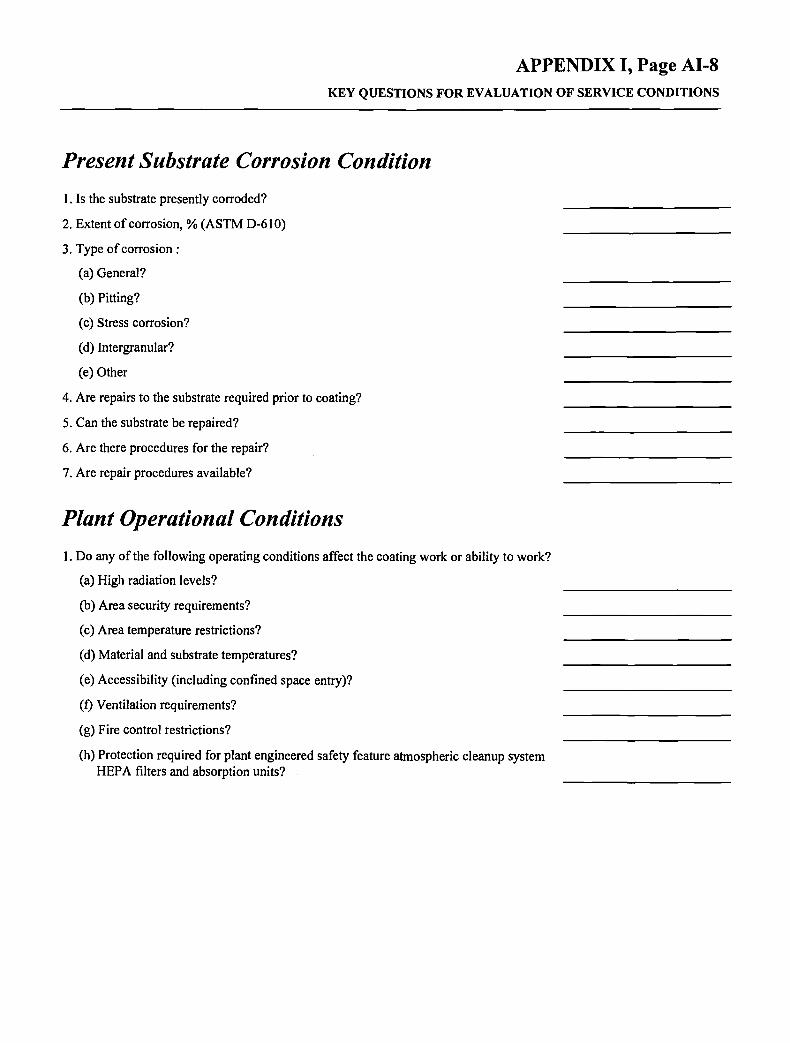
APPENDIX I, Page AI-8 KEY QUESTIONS FOR EVALUATION OF SERVICE CONDITIONS
Present Substrate Corrosion Condition 1. Is the substrate presently corroded?
2. Extent of corrosion, % (ASTM D-610)
3. Type of corrosion :
(a) General?
(b) Pitting?
(c) Stress corrosion?
(d) Intergranular?
(e) Other
4. Are repairs to the substrate required prior to coating?
5. Can the substrate be repaired?
6. Are there procedures for the repair?
7. Are repair procedures available?
Plant Operational Conditions
1. Do any of the following operating conditions affect the coating work or ability to work?
(a) High radiation levels?
(b) Area security requirements?
(c) Area temperature restrictions?
(d) Material and substrate temperatures?
(e) Accessibility (including confined space entry)?
(f) Ventilation requirements?
(g) Fire control restrictions?
(h) Protection required for plant engineered safety feature atmospheric cleanup system HEPA filters and absorption units?

APPENDIX I, Page AI-9 KEY QUESTIONS FOR EVALUATION OF SERVICE CONDITIONS
Radiation Levels
1. Is the substrate radioactively contaminated?
2. Is the substrate radioactive?
3. Are the general area radiation levels v̂ fithin acceptable limits? [Verify with Plant Health Physics (HP) Department.]
4. Is there airborne contamination? (Verify with Plant Health Physics Department.)
5. Will surface preparation generate airborne contamination?
6. Type of breathing apparatus and clothing required? (Verify with Plant Health Physics Department and OSHA requirements.)
7. Is decontamination practical?
8. Should decontaminability be considered in the future?
9. If decontamination is not practical, can the contamination be sealed to the substrate?
10. Will special ventilation and filtration equipment be required?
11. Are special procedures required for the ventilation equipment operation?
12. Are special and additional arrangements required for contaminated material disposal?
In-service Inspection Requirements
1. Does the substrate require inspection as a part of an in-service inspection program?
2. Can the substrate remain uncoated to facilitate inspection?
Time Constraints
1. Can the coating work be completed at one time?
2. Should the coating work be divided into phases?
3. If the work is to be completed in phases, is the material/equipment to remain onsite?
4. Has the remobilization of workers been negotiated?

APPENDIX I, Page AI-10 KEY QUESTIONS FOR EVALUATION OF SERVICE CONDITIONS
Weather/Climatic Conditions
1. Is the work area susceptible to adverse climatic conditions?
2. Can the work area be protected from the adverse conditions?
3. Are there temperature and humidity requirements for the coating material?
4. Have provisions been made to control temperature and humidity?
5. Can work area cleanliness be maintained?
6. Equipment placement and protection evaluated?
7. Equipment operation evaluated?
8. Material storage requirements considered (i.e., heating and ventilation requirements)?
9. Personnel considerations?
Material/Waste Disposal
1. Disposal requirements for the coating material waste checked?
2. Disposal requirements for the surface preparation material checked?
3. Disposal of radioactively contaminated material arranged?
Ventilation Requirements
1. Humidity control required? (Refer to coating data sheets.)
2. Temperature control required? (Refer to coating data sheets.)
3. Particulate filtration required? (Refer to OSHA requirements.)
4. Confined entry precautions?
5. Explosive concentrations to be monitored?
6. Air changes per hour calculated and adequate?
Safety Requirements
1. Personnel safety requirements checked? (Refer to Health Physics, OSHA, Mine Safety and Health Administration (MSHA), NIOSH, EPA, NRC, company and plant requirements)

MNL28-EB/NOV. 1995
< X
o
u lU _ l UJ (0
o z < o o >< o z UJ Q.
<
( 0
s UJ 1 -( 0 >• ( 0 Q£ UJ 1 -< 1 CD z J O O o u. O ( 0 H Z UJ
z o Q.
s o o
—
X a z LU
a. <
M
M z Q Z O u s < UJ M Z
<
•g "S .2 1 o 3)
UJ
o z < X o >< UJ
< UJ X a z <
10
II 11 " » • - , -.S 5 .E "5 5 •*
o •- " O l U>
:i » 8 1 O 1-
o> c 'S.
ol M 10
E 1 -̂ 3 10 <B a >
M
10 I3> IS 3
1^ 2 1 -
(0 c
i i il B (0
<« 0)
0) ^i J£ O
c *i — (0
O
< O W O U J
^ ^
UJ
z UJ
o
X
><
><
X
X
X
X
X
X
X
(A a> " 5 o a UJ
i2 "3 o o
X
X
X
X
X
X
X
X
X
X
X
X
>« >• 5 X O
o a & 0)
« =5 » 9 o c
o u, a.
O 0}
1- >.
X
X
X
X
1 i 1
X
X
X
X
X
X
X
X
X
X
"w" iR
o 5 t_ S 5 S S !:; cB in o = o «
o u := u
= i c ^ M O 10 (0 1)
X
X
X
M •) _c 'E li w a> n A 3
a:
X
X
X
X
X
X
^
=, g M ^ Ol C C O
'S O ID — O V U W
M f
- &
— ^ 3 N o u.
X
(A Ol c
o u M
«
a> ]0
X
X
X
X
X
X
X
X
X
X
>> so a
S 0)
S "5
i 0)
£ 1-
X
X
1 i
X
X
X
M 0)
1 a> 10 £ a.
• o o o 3
^ 4) (Q 0 "5 .c (0 CO (A
c Q) c Q Q* £ Q O
E 4)
• * - •
10 >« M w V * ; 5 S O) c = o 0 o i : o iS
1 (U ^ (0 c
1 •D — 3
1 10 •o c (S ^ ^
s ^ 3
o 3 W
1 $
1 9
1 S .2 iS
i ^ ai c s 2 8 ^ « c o a 4)
£
to' c ,2 ^ •a e 0 o o o
E (0
X) c n j5 "5 E o •^ w o 3
^ 4 o £ 3 C IS E c o at c c
0) •D £» IS >
5
8 c IS E
2L CO e
0 o UJ h-o z 1 -z < fc OL o a. S

MNL28-EB/NOV. 1995
(0 I-u 3 Q O OC a. o < o o u il o lU Q. (0 u.
o z o (0
s s o o o z < u.
o z g < 3 < > UJ QC O u. (O Q
o X H UJ
S H-(0 UJ O UJ H-(0 UJ O O 3 (0
><
Q Z LU Q. Q. <
«< (0
S
§ 1 0) CO O) 3
(0
(0 o
a 2
Q . • (5 o (A
a.
CM
Q
c o
•<rt
•o
<
c 0} K
/—s
17) J3
15 <1>
eg o o —̂ Q
Q
(0
O
3 Q.
(O a>
O
c o
•55 c (0
CO
V £ 1-
r<~
> t
2 a. (0
to CO
00
(!)
•£
E T3 C 0
Q 0
0
CO 0
CM
U L
co" vn
Q CO C]>
UJ
>.
CO
g Q. l _ 0 a ^ 0)
i
00 (O
00
0 CM'
CO
Q
a> u c CO
'in
a: CO 0
E £ 0
1
t
UJ 0 <f z
tn 0 CO CM 0
3 c £ CO Ci
0
Q
* j
v> 0 1 -
S
So •0 "S
0) CD o> 3 (0
(0 «
0) a 2
Q .
"(5 0 '<» >«
a.
CM
CM I f
Q
8 c CO
t ) a> 0: c 0
2 n <
0 CO 0
Q
0 0
5 <
CO
>s
00 CO
0
> 10 S < O)
_c "co u. >< n
00
CO
Q
CO
OQ
<
00 0 CO
Q CM"
• > *
Q
c £
(0 c 0) 1-
00 CO CO
0 CM'
5 Q
c g
at c
UJ
0 •«1-CM CM
Q
c •s CO I
1 0
CO
Q
£
c £
>
£ Q. E 0 0
0
Q
c £ CO
S .11 (U
u.
CO m CM
Q
8 c CO
Vi 'to «
S E
0
c-
1
CM CO
Q
8 c CO
Vi
0: CO g> H
M
i! tJ 3
I Q.
« 4 ^
O) _e 'c E
« •a c (0
'io (A
e eg Cj M E 4)
><
c •s 0 0 0 1^ I 1 ^
0
d)
5 S. 0 Q.
0
E
"5 0
1 O.
0 e 0 .2 ra a E 0 0
(0 111 H 0 Z Z < ^ 0 0. S
<« 1 M H
CB 0
1 S *• 1 ? g. fe 0 a s £ 3 0
"i S> .£
1 1 0
1 1 1 0 )
s 3
^ 1 8 « M
? n 0) w •s
1 4= 0
3 (0 w
1 2 3 0 5 & w 3
J : • • •0
g ^'
1 E H 0) 4S
S 4) 1^ ^ E 2
•5 M
a E
1 t>
1 9 3
1 » e
E 0)
ts > i (0
0 (I
i
•5 0 0
« 4= j ^
0 W
• M
c 0) e
a E 0 0
•5
& £ ^ (0 . 0 a. a (S
il •s c (S
E c
1 W
£
E
10
•E
0 c 0 .
t) — tt
. ; i i: & * i »
= "S c u c
s. i £
1 = 1 4)
J3
1 E
1 S 1 3 M w
5 t; £
$
1 (U
^
1 1 • M
1 1
1 1 0 5 w
1 3
S £


