51
Joint Presentation by: AT&T T-Mobile Verizon Wireless Beaverton OR City Council October 9, 2018

Joint Presentation by:
AT&T T-Mobile Verizon Wireless
Beaverton OR City CouncilOctober 9, 2018

• Network Evolution--dramatic growth
• What is the difference between a small cell and a macrosolution?
• What are the components of a small cell installation?
• What antenna variations exist?
• Types of Small Wireless FaciilitiesUtility Pole Strand MountLight Standards
Topics
2

Network Evolution
3

Network Evolution
4

The footprint, or service area, of a site is determined by height and by frequency band
0.5 to 20 miles
75 to 400 feet
Macrocell (4G LTE)The common form factor for wireless communication. Higher height and lower frequencies used result in the larger service area.
30 to 60 feet
500 to 1200 ft
30 to 60 feet
250 to 750 ft
Current Small Cell (4G LTE)Uses the same frequencies as macrocells, in addition to utilizing unlicensed spectrum. Due to lower height, footprint is smaller. Increases capacity or coverage in target areas.
Future Small Cell (5G)Very high frequencies enabled by future 5G technology will result in a smaller footprint, but can be used to meet the exponential increased capacity demand. These frequencies are not used for wireless service today.
• Heights and service areas areapproximations• Small cell sites supplement vs. replace macrocellsites
5

Network Evolution
Small Cell
Macrocell
Cell-edge Mid-cell Near Cell Mid-cell Cell-edge
Small Cell
Small Cell
Small Cells
Small Cell
6

What is the difference between a small cell and a macro solution?
7

Small vs. Macro Cell – Antenna
Typical Macro Cell Antenna
•6 or 8 ft. in Height•6 to 12 per pole•Install Height 80 to 200 ft.•2 to 4 Large Ground Cabinets or in an Equipment Room
Typical Small Cell Antenna
• ~2 ft. in Height• 1 to 3 per Pole• Install Height of 20 to 40 ft.• No Ground Cabinet
8

Small vs. Macro Cell – Pole Height
Small Cell Macro Cell
9

Small vs. Macro Cell – Install
Macro Site on Utility Pole
Small Cell on Utility Pole
4 to 6 Large Cabinets on Adjacent Property
1 to 3 Small Antennas
Small Radio Enclosure No Ground Cabinets
3 to 12 Large Antennas
10

What are the components of a small cell installation?
11
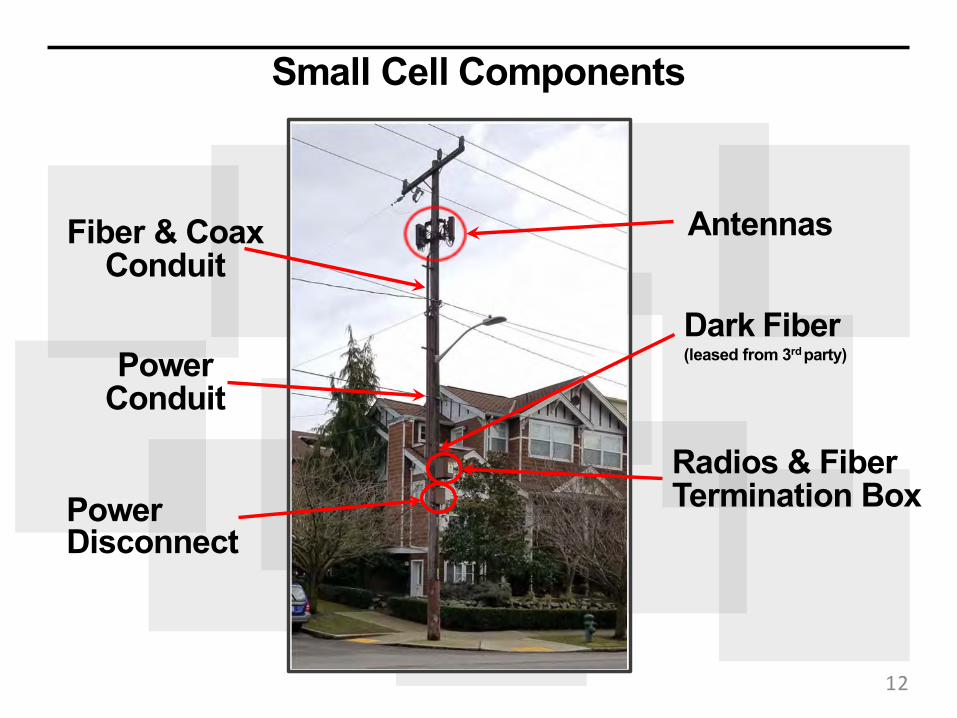
Small Cell Components
Antennas
Dark Fiber(leased from 3rdparty)
Radios & Fiber Termination Box
Fiber & Coax Conduit
Power Conduit
Power Disconnect
12

Small Cell Components(1) Antenna
(3) Relay Antenna
(4) AC Distribution
(2) Remote Radio Unit
13

What antenna variations exist?
14

15
Antenna Options
Cylindrical
Panel
Height~2 ft.
Diameter16 in.~ Height
~2 ft.
Width1 to 3 ft.

16
Small Cell Antenna Examples – Pole Top/Stand-off Bracket Mount

25
§ Sleek design§ Creates uniformity§ Two Configurations: (1) Antennas and radios in
close proximity in a unified shroud for improved performance (faster data speeds); or (2) radios in shroud connected to external omni-directional antenna
§ Can blend with existing infrastructure
T-Mobile’s Small Cell Shroud
17

26 T-Mobile Confidential
T-Mobile’s Strand-Mount Solution
18

Utility Poles
19

First Bellevue Installation – Archerline
20
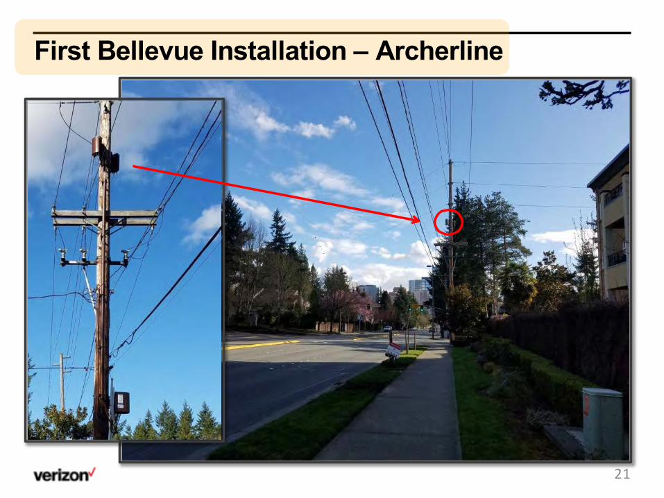
First Bellevue Installation – Archerline
21

First Bellevue Installation – Archerline
22

Locally Built Sites
23

Example small cell photo-simulation, actual design may differ.
24

36
Wood Pole Installations
Jacksonville, FL Baltimore, MD
25

Strand Mounts
26

Strand Mount – Seattle Trial
The power disconnect is mounted to the pole
Combined antenna and radio units are mounted to a bracket that his hung on the fiber strand.
Fiber runs into the radiosfrom nearby fiber termination box.
Conduit contains power lines running from the supply space to the power disconnect and then to the antenna and radio units.
27

Strand Mount – Simulation
(Simulation)
28

40 T-Mobile Confidential
Strand Mount Installation (Salt Lake City)
29

41 T-Mobile Confidential
Strand Mount Installation (Phoenix)
30

42 T-Mobile Confidential
Strand Mount Installation (Phoenix)
31

Light Standards
32

Light Standard
(Simulation) 33

34New small cell decorative pole next to existing pole before removal.
Light Standards-Good Design Matters

Light Standard
City of Bellevue
Puget Sound Energy
(Simulation) (Simulation)
35

36
Light Standard
Minneapolis, MN Kansas City, KS

|
xxx
NATIONAL DEVELOPMENT
T-Mobile Confidential1
Light Standard Examples
Phoenix, AZ
Las Vegas, NV
33737

Wireless Only Poles
38

|
xxx
NATIONAL DEVELOPMENT
T-Mobile Confidential2
Wireless Only PolePole Specs Photo SimulationBellevue, WA
39

40
Wireless Only Poles
(Simulation)

Portland Designs
41

Accuracy of photo simulation based upon information provided by project applicant.
©2018 Google Maps
Looking west from Dekum StreetProposedExisting
View 1
proposed cantenna
proposed equipment enclosure
proposed replacement light standard
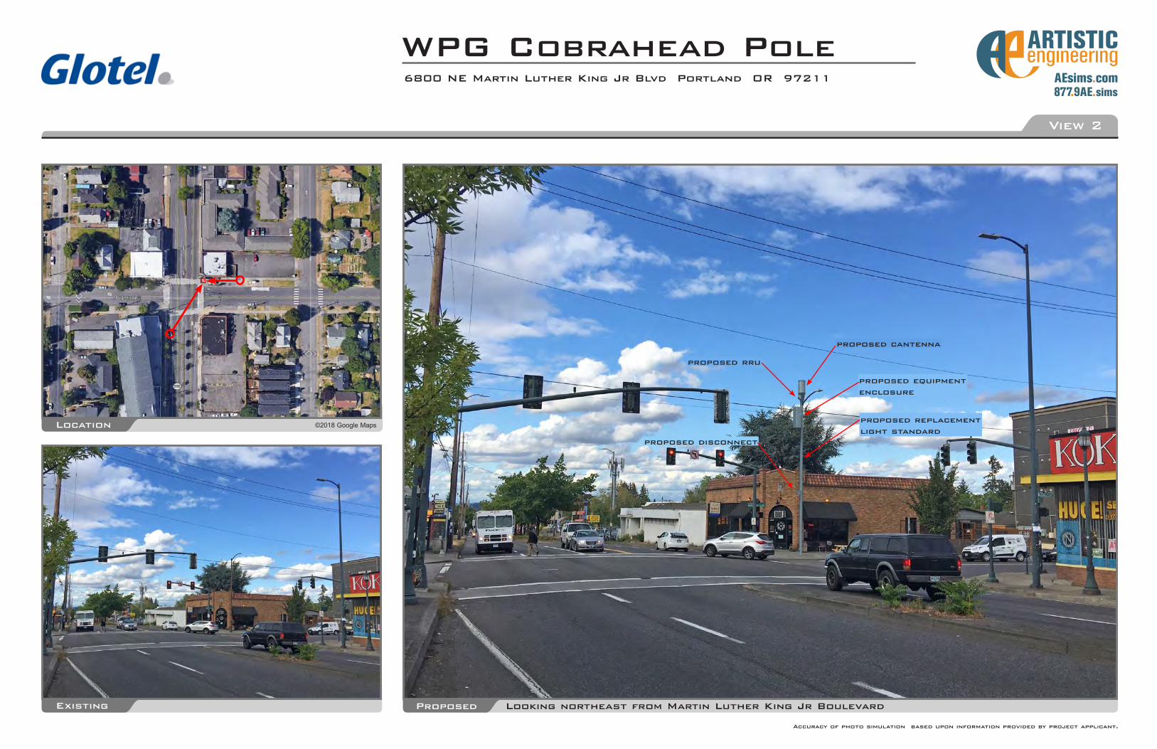
WPG Cobrahead Pole6800 NE Martin Luther King Jr Blvd Portland OR 97211
43
Accuracy of photo simulation based upon information provided by project applicant.
©2018 Google MapsLocation
Existing Looking northeast from Martin Luther King Jr BoulevardProposed
View 2
proposed cantenna
WPG Cobrahead Pole6800 NE Martin Luther King Jr Blvd Portland OR 97211
proposed rru
proposed equipment enclosure
proposed replacement light standard
proposed disconnect

Accuracy of photo simulation based upon information provided by project applicant.
©2018 Google MapsLocation
Existing Looking northeast from SW Hall StreetProposed
View 1
proposed cantenna
WPG Decorative Street Light PoleSW Hall St & SW 4th Ave Portland OR 97201
proposed rru
proposed equipment enclosure behind banners
proposed replacement light standard proposed disconnect
44

Accuracy of photo simulation based upon information provided by project applicant.
©2018 Google MapsLocation
Existing Looking southwest from SW 4th AvenueProposed
View 2
proposed cantenna
WPG Decorative Street Light PoleSW Hall St & SW 4th Ave Portland OR 97201
proposed rru
proposed equipment enclosure behind banners
proposed replacement light standard
proposed disconnect
45

Accuracy of photo simulation based upon information provided by project applicant.
©2018 Google MapsLocation
Existing Looking southeast from SW BroadwayProposed
View 1
proposed cantenna
WPG Dual Mast Arm Pole (No SL)SW Columbia St & SW Broadway Portland OR 97201
proposed rru
proposed equipment enclosure
proposed replacement light standard
proposed disconnect
46

Accuracy of photo simulation based upon information provided by project applicant.
©2018 Google MapsLocation
Existing Looking southeast from SW Columbia StreetProposed
View 2
proposed cantenna
WPG Dual Mast Arm Pole (No SL)SW Columbia St & SW Broadway Portland OR 97201
proposed rru
proposed equipment enclosure
proposed replacement light standardproposed disconnect
47

Conceptual Beaverton Designs
48

49

50

Thank you!
51


