A Project Document of the ATC Application Programming Interface Working Group ATC APIRI FIO SDD v01.002 Software Design Description (SDD) for the Advanced Transportation Controller (ATC) Application Programming Interface (API) Reference Implementation Project April 18, 2014 SDD in support of: USDOT Contract # DTFH61-11-D-00052, Task Order # T-13-003 For use by: Siva Narla, Chief Engineer and ITS Standards Manager Institute of Transportation Engineers George Chen and Douglas Tarico, Co-Chairs ATC API Working Group Ralph W. Boaz, Project Manager and Systems Engineer ATC API Reference Implementation Project Members of the ATC API Working Group Consulting Team for the ATC API RI Project 1
Transcript
A Project Document of the ATC Application Programming Interface Working Group
ATC APIRI FIO SDD v01.002
Software Design Description (SDD) for the Advanced Transportation Controller (ATC) Application Programming Interface (API) Reference Implementation Project
April 18, 2014
SDD in support of: USDOT Contract # DTFH61-11-D-00052, Task Order # T-13-003
For use by: Siva Narla, Chief Engineer and ITS Standards ManagerInstitute of Transportation Engineers
George Chen and Douglas Tarico, Co-ChairsATC API Working Group
Ralph W. Boaz, Project Manager and Systems EngineerATC API Reference Implementation Project
Members of the ATC API Working Group
Consulting Team for the ATC API RI Project
Prepared by: Michael Gallagher, Intelight, Inc.Douglas Crawford, Intelight, Inc.Grant Gardner, Intelight, Inc.Ralph W. Boaz, Pillar Consulting, Inc.
Ó Copyright 2014 AASHTO/ITE/NEMA. All rights reserved.
1
CHANGE HISTORY
DATE NOTE04/16/14 Addressed feedback from first review. Update Compliance Traceability
Joint NEMA, AASHTO and ITE Copyright andAdvanced Transportation Controller (ATC)
Application Programming Interface (API) Working Group
These materials are delivered "AS IS" without any warranties as to their use or performance.
AASHTO/ITE/NEMA AND THEIR SUPPLIERS DO NOT WARRANT THE PERFORMANCE OR RESULTS YOU MAY OBTAIN BY USING THESE MATERIALS. AASHTO/ITE/NEMA AND THEIR SUPPLIERS MAKE NO WARRANTIES, EXPRESSED OR IMPLIED, AS TO NON-INFRINGEMENT OF THIRD PARTY RIGHTS, MERCHANTABILITY, OR FITNESS FOR ANY PARTICULAR PURPOSE. IN NO EVENT WILL AASHTO, ITE, NEMA, OR THEIR SUPPLIERS BE LIABLE TO YOU OR ANY THIRD PARTY FOR ANY CLAIM OR FOR ANY CONSEQUENTIAL, INCIDENTAL, OR SPECIAL DAMAGES, INCLUDING ANY LOST PROFITS OR LOST SAVINGS ARISING FROM YOUR REPRODUCTION OR USE OF THESE MATERIALS, EVEN IF AN AASHTO, ITE, OR NEMA REPRESENTATIVE HAS BEEN ADVISED OF THE POSSIBILITY OF SUCH DAMAGES. Some states or jurisdictions do not allow the exclusion or limitation of incidental, consequential, or special damages, or exclusion of implied warranties, so the above limitations may not apply to you.
Use of these materials does not constitute an endorsement or affiliation by or between AASHTO, ITE, or NEMA and you, your company, or your products and services.
If you are not willing to accept the foregoing restrictions, you should immediately return these materials.
2 REFERENCES.............................................................................................93 FIO API Design Views..................................................................................10
3.1 FIO API Decomposition Description.................................................................................103.2 FIO API Dependency Description....................................................................................113.3 FIO API Interface Description..........................................................................................133.4 FIO API Detailed Design..................................................................................................15
4 FPUI API Design Views.................................................................................244.1 FPUI API Decomposition Description..............................................................................244.2 FPUI API Dependency Description..................................................................................244.3 FPUI API Interface Description........................................................................................254.4 FPUI API Detailed Design................................................................................................27
5 TOD API Design Views.................................................................................335.1 TOD API Decomposition Description...............................................................................335.2 TOD API Dependency Description...................................................................................335.3 TOD API Interface Description.........................................................................................335.4 TOD API Detailed Design................................................................................................34
This Software Design Document (SDD) has been developed for the project named “Reference Implementation of ATC 5401 Application Programming Interface (API) Standard Version 2” under the United States Department of Transportation (USDOT) Contract Number DTFH61-11-D-00052, Work Order T-13003 (referred to as the APIRI Project). This SDD provides the software structure, software components, interfaces and data necessary for the subsequent implementation of the FIO software. It provides traceability from the requirements within the ATC 5401 Standard and the design elements to ensure that each requirement is completely addressed. This SDD has been developed for:
a) The USDOT Intelligent Transportation Systems (ITS) Joint Program Office (JPO) who is sponsoring the work and requires the use of a formal software development process;
b) The consulting team contracted to develop the software described; and
c) The consultants, manufacturers, and public transportation professionals who participate in the API Working Group (WG) who provide domain expertise, quality assurance, testing assistance and the maintenance of the software; and
d) The transportation industry as a whole that will depend upon the software produced from this SDD to support operational programs on ATC controller equipment.
This document provides a Software Design Specification (SDD) for all software libraries defined by ATC 5401 Application Programming Interface (API) Standard Version 2. This includes the following libraries:
Field Input/Output (FIO) software library Front Panel System (FPS) software library Time of Day (TOD) software library
1.2 Scope
The ATC 5401 ATC API standard defines an interface to enable a broad ATC software platform that, when combined with the ATC O/S, forms a universal interface for application programs. This API interface allows application programs to be written so that they may run on any ATC controller unit regardless of the manufacturer. It also defines a software environment that allows multiple application programs to be interoperable on a single controller unit by sharing the fixed resources of the controller.
5
The APIRI project and the design described within this SDD document builds upon the ATC 5401 API standard work to provide a fully functional and verified open source reference implementation of the ATC API interfaces. The APIRI satisfies all ATC 5401 API functional requirements and can be leveraged by multiple manufactures, with the goal of simplifying ATC platform development.
1.3 Document Organization
This SDD provides a detailed description of the three major ATC API software library components – specifically, the Field Input/Output (FIO) software library, the Front Panel System (FPS) software library and the Time of Day (TOD) software library. The design information has been organized based on IEEE Std 1016-1998, IEEE Recommended Practice for Software Design Descriptions. The design is presented using the following concepts:
Design Entity – An element of design that is structurally and functionally distinct from other elements and that is separately named and referenced.
Design Entity Attribute – A characteristic or property of a design entity. Design View – A subset of design entity attribute information that is specifically
suited to the needs of a software project activity.
Each major API software library is described in a separate section and organized by the following design views:
Decomposition Description – This design view provides an entity breakdown for the library;
Dependency Description – This design view highlights any dependencies on the software to be developed;
Interface Description – This design view presents the high level interfaces of the software library; and
Detailed Design – This design view presents the functional design of each entity.
This SDD may be updated during the implementation phase of the project to reflect design elements not accounted for in previous phases of development. A traceability matrix is included to ensure all ATC API requirements are incorporated and linked to specific design elements.
1.4 Definitions and Acronyms
Term DefinitionAASHTO American Association of State Highway and
Transportation OfficialsAPI Application Programming InterfaceAPI Managers API software that manages an ATC resource for use by
concurrently running application programs.API Utilities API software not included in the API Managers that is
used for configuration purposes.
6
Term DefinitionAPIRI API Reference Implementation (software)APIRI Project Entire project managed by this PMP including software,
hardware and documentation.APIVS API Validation Suite (software and fixture)Application Program Any program designed to perform a specific function
directly for the user or, in some cases, for another application program. Examples of application programs include word processors, database programs, Web browsers and traffic control programs. Application programs use the services of a computer's O/S and other supporting programs such as an application programming interface.
API Application Programmer InterfaceATC Advanced Transportation ControllerATC Device Drivers Low-level software not included in a typical Linux
distributions that is necessary for ATC-specific devices to operate in a Linux O/S environment.
ATP Authorization to ProceedBoard Support Package
Software usually provided by processor board manufacturers which provides a consistent software interface for the unique architecture of the board. In the case of the ATC, the Board Support Package also includes the O/S
BSP See Board Support PackageConOps Concept of OperationsCO Contracting OfficerCOR Contract Officer’s RepresentativeCOTM Contract Officer’s Task ManagerCPU Central Processing Unit. A programmable logic device
that performs the instruction, logic and mathematical processing in a computer.
Device Driver A software routine that links a peripheral device to the operating system. It acts like a translator between a device and the application programs that use it.
FHWA Federal Highway AdministrationFIO Field Input and OutputFIOMAN Field I/O ManagerFIOMSG Field I/O Message SchedulerFPMW Front Panel Manager WindowFPUI Front Panel User InterfaceH/W Hardware
7
Term DefinitionI/O Input/OutputIEC International Electrotechnical CommissionIEEE Institute of Electrical and Electronics EngineersISO International Organization for StandardizationITE Institute of Transportation EngineersITS Intelligent Transportation SystemsJC Joint CommitteeJPO Joint Program OfficeLinux Low-level software that is freely available in the Linux
community for use with common hardware components operating in a standard fashion.
Linux Kernel The Unix-like operating system kernel that was begun by Linus Torvalds in 1991. The Linux Kernel provides general O/S functionality. This includes functions for things typical in any computer system such as file I/O, serial I/O, interprocess communication and process scheduling. It also includes Linux utility functions necessary to run programs such as shell scripts and console commands. It is generally available as open source (free to the public). The Linux Kernel referenced in this standard is defined in the ATC Controller Standard Section 2.2.5, Annex A and Annex B.
N/A Not ApplicableOperational User A technician or transportation engineer who uses the
controller to perform its operational tasks.O/S Operating SystemOSS Open Source SoftwarePCB Printed Circuit BoardPMP Project Management PlanPOP Period of PerformancePRL Protocol Requirements ListRI Reference ImplementationRITA Research and Innovative Technology AdministrationRTC Real-Time ClockRTM Requirements Traceability MatrixSDD Software Design Document or Software Design
DescriptionsSDO Standards Development OrganizationSE Systems EngineerSEP Systems Engineering ProcessSEMP Systems Engineering Management Plan
8
Term DefinitionSOW Statement of WorkSPDD Serial Port Device DriverSRS Software Requirements SpecificationS/W SoftwareTBD To Be DeterminedTOD Time of DayTOPR Task Order Proposal RequestTX TransmissionUS United StatesUSDOT United States Department of TransportationUser Developer A software developer that designs and develops
programs for controllers.Walkthrough A step-by-step presentation by the author of a document
in order to gather information and to establish a common understanding of its content.
WBS Work Breakdown StructureWG Working Group
2 REFERENCES
Institute of Electrical and Electronics Engineers, IEEE Std 1016-1998, IEEE Recommended Practice for Software Design Descriptions. IEEE, 1998.http://standards.ieee.org/index.html
Institute of Transportation Engineers, ATC 5201 Advanced Transportation Controller (ATC) Standard Version 06. ATC Joint Committee, 30 July 2012.http://www.ite.org/standards/index.asp
Institute of Transportation Engineers, ATC 5401 Application Programming Interface (API) Standard for the Advanced Transportation Controller (ATC) v02. ATC Joint Committee, 15 September 2013. http://www.ite.org/standards/index.asp
Institute of Transportation Engineers, ATC APIRI PMP v01.01 Project Management Plan (PMP) for the Advanced Transportation Controller (ATC) Application Programming Interface (API) Reference Implementation Project. ATC Joint Committee, 3 January 2014.http://www.ite.org/standards/index.asp
Institute of Transportation Engineers, ATC APIRI SEMP v01.01 Systems Engineering Management Plan (SEMP) for the Advanced Transportation Controller (ATC) Application Programming Interface (API) Reference Implementation Project. ATC Joint
Committee, 3 January 2014.http://www.ite.org/standards/index.asp
3 FIO API DESIGN VIEWS
The following design views show decomposition, dependency, interface and detail aspects of the proposed design for the Field I/O API reference implementation. This design is intended to meet the general requirement of allowing multiple application programs to share access to the Field I/O Device resources of the ATC platform.
3.1 FIO API Decomposition Description
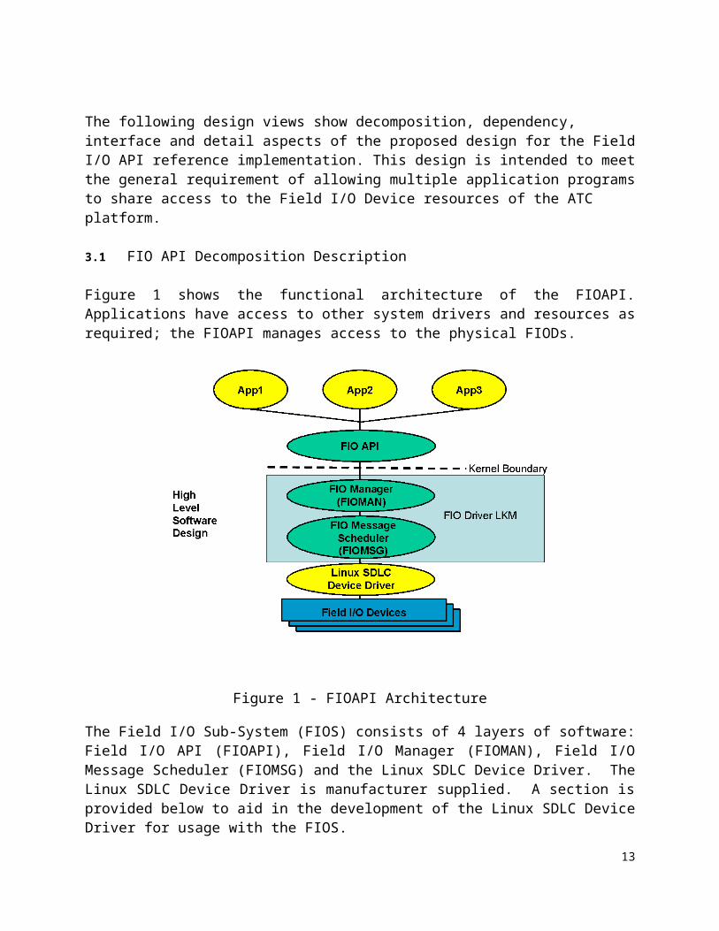
Figure 1 shows the functional architecture of the FIOAPI. Applications have access to other system drivers and resources as required; the FIOAPI manages access to the physical FIODs.
Figure 1 - FIOAPI Architecture
The Field I/O Sub-System (FIOS) consists of 4 layers of software: Field I/O API (FIOAPI), Field I/O Manager (FIOMAN), Field I/O Message Scheduler (FIOMSG) and the Linux SDLC Device Driver. The Linux SDLC Device Driver is manufacturer supplied. A section is provided below to aid in the development of the Linux SDLC Device Driver for usage with the FIOS.
The FIOAPI is a user level library that provides a consistent and orthogonal interface to
the FIOS. The FIOMAN and FIOMSG Software exist as part of the FIO Driver. The FIO Driver is provided as a Loadable Kernel Module (LKM). The FIOMAN is executed as an extension of a user process. The FIOMSG layer is a collection of Kernel Timer based tasks. One task is used for transmission (TX) of FIOD request frames. A second task is utilized for the polling and reception (RX) of FIOD response frames.
FIOAPI provides:
• Abstraction for Applications to access FIO API Services• Consistent / Orthogonal Application Interface to FIODs• Interface to FIOS Kernel Tasks• Functions to Support all ATC5401 API Standard Requirements• Easy extensibility
FIOMAN provides:
• Synchronicity of requests and responses with applications• Control of access to FIODs; FIOMAN knows what applications have reserved
and how to access a FIOD• Health Monitor Functionality• Watch Dog Functionality• Manages API responses• Manages view of application data to a FIOD• Manages view of FIOD data to applications• Transition Buffer handling
FIOMSG provides:
• Control of sending and receiving of request and response frames• Handles multiple ports• Merges the 3 ports into 1 application stream from the FIOMAN point of view• Manages a list of the last response frame of each type for each FIOD• Manages queues of request frames to be sent in timed frequency output order;
by port• Response frames are matched with request frames.
3.2 FIO API Dependency Description
FIOMSG depends on the Linux SDLC Kernel Device Driver for communicating frame data to and from the FIODs. The Linux SDLC Kernel Device Driver is provided by each manufacturer as part of the ATC BSP. An overview of the SDLC Kernel Device Driver interface is provided in the ATC 5201 Advanced Transportation Controller (ATC) Standard Version 06 specification in Section B.6
The FIOAPI depends on the FIOMAN entity of the FIO Driver LKM for the user space to system space function call invocation.
11
3.2.1
12
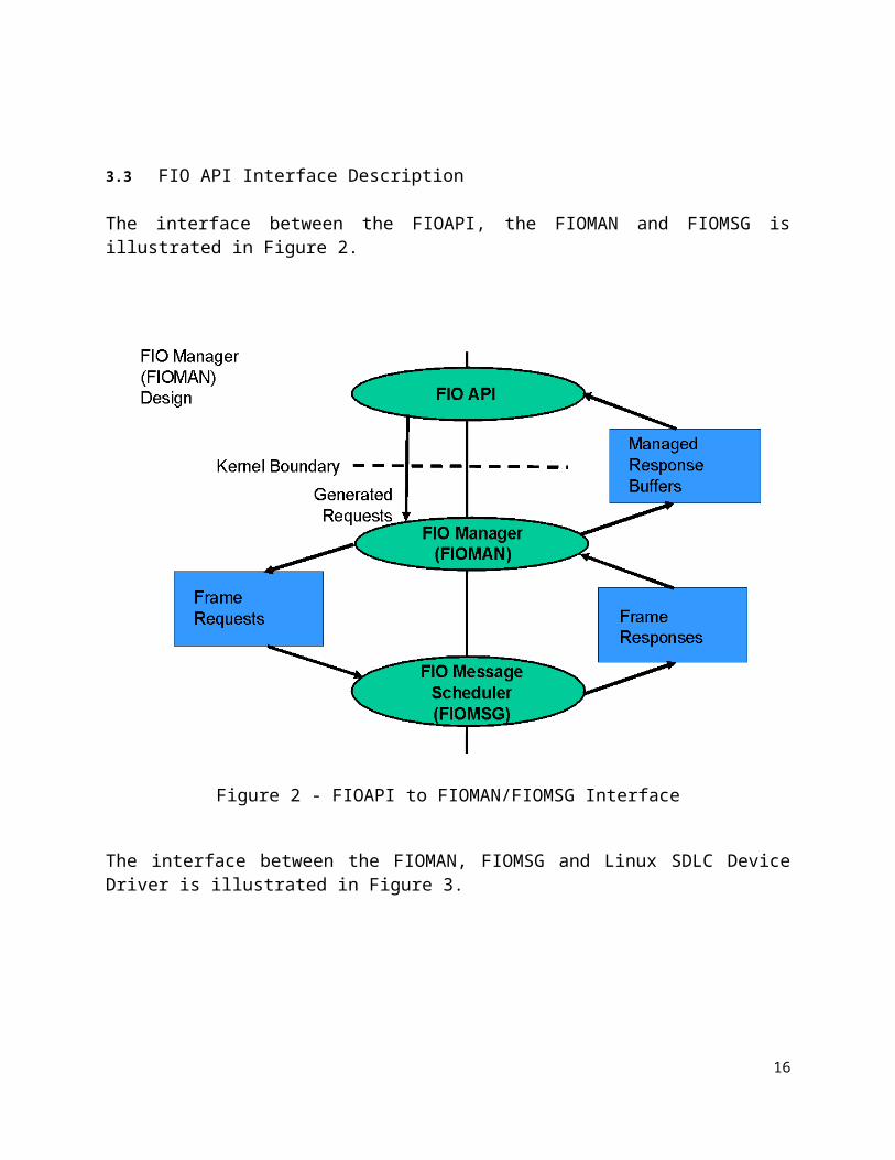
3.3 FIO API Interface Description
The interface between the FIOAPI, the FIOMAN and FIOMSG is illustrated in Figure 2.
Figure 2 - FIOAPI to FIOMAN/FIOMSG Interface
The interface between the FIOMAN, FIOMSG and Linux SDLC Device Driver is illustrated in Figure 3.
13
Figure 3 - FIOMAN/FIOMSG to SDLC Driver Interface
The interface provided by the Linux SDLC Kernel Device Driver consists of a list of kernel level global functions as follows:
int sdlc_kernel_ioctl( void *context, int command, parameters );
Full details of this interface are provided in the ATC 5201 Standard Ver 06 specification in Section B.6,
14
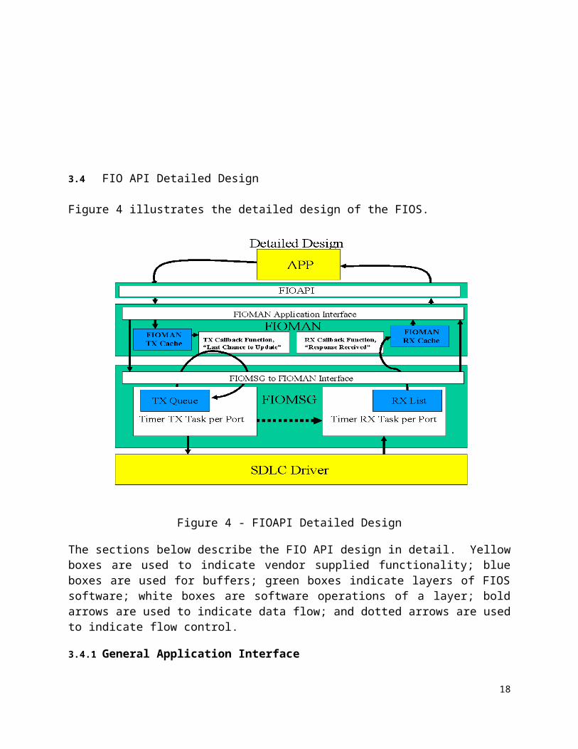
3.4 FIO API Detailed Design
Figure 4 illustrates the detailed design of the FIOS.
Figure 4 - FIOAPI Detailed Design
The sections below describe the FIO API design in detail. Yellow boxes are used to indicate vendor supplied functionality; blue boxes are used for buffers; green boxes indicate layers of FIOS software; white boxes are software operations of a layer; bold arrows are used to indicate data flow; and dotted arrows are used to indicate flow control.
3.4.1 General Application Interface
All applications interface to the FIOS through the FIOAPI library. This user space library, libfioapi.a, is linked in by an application and provides all required functions to support the FIOAPI requirements.
DEFINITION: An application is a single Linux Process, as defined by a unique process id. If output points need to be shared between processes, this sharing must be done at a higher level. Writing of an output point is exclusive to a Linux Process. If 2 or more Linux Processes want to write to the same output point; this sharing must be solved by the user of the FIOAPI. The FIOAPI does not directly support this.
15
3.4.2 Field I/O API (FIOAPI)All applications interface to the FIOS through the FIOAPI library. This user space library, libfioapi.a, is linked in by an application and provides all required functions to support the FIOAPI requirements. The ATC5401 API Standard contains detailed descriptions and prototypes for all FIOAPI functions.
The FIOAPI layer is a thin layer of software that removes the need for application developers to know how to interface to the FIOS. There are 5 system level functions supported by the FIO Driver LKM: open(), close(), read(), write() and ioctl(). All FIOAPI functions map to one or more of these system level function calls. In general, most FIOS operations are supported by an ioctl() command.
The FIOAPI interfaces through these system level function calls to the FIOMAN. The FIOAPI generates requests through a system level function to the FIOMAN and receives responses from the FIOMAN through alternate system level function calls.
The list of functions supported by the FIOAPI, detailed in ATC5401 API Standard section 4.2, is:
Detailed descriptions of each function can be found in the ATC 5401 API SRS document.
3.4.3 Field I/O Manager (FIOMAN)FIOMAN is the top layer of software of the FIO Driver LKM. This layer manages all access to and activity of the FIO Driver LKM. The FIOMAN layer executes as an extension of a user application process in Kernel Space.
FIOMAN, upon application request for action, either sets information into its internal cache, performs housekeeping activities (such as health monitoring), or interacts with the FIOMSG layer to cause a Request Frame to be sent to a FIOD.
FIOMAN also services all Health Monitor (HM) operations, keeping track of the health status of applications that choose to register with the health monitor service using the fio_hm_register API.
Applications that register for health monitoring will be monitored until deregistered by calling the fio_hm_deregister.
17
FIOMAN keeps internal state for all registered applications (up to 16) when registered which includes the heartbeat timeout of all registered applications.
If an application fails to call the fio_hm_heartbeat API within the timeout period, the application will be marked as failed. A fault condition can be cleared with fio_hm_fault_reset API call.
FIOMAN, upon application request for response information, either queries its internal cache for the required response information, or requests FIOMSG for the appropriate Response Frame.
FIOMAN maintains two separate views of information: what the application (APP view) currently knows about, has enabled, has set, or has reserved, etc.; and a view of what all applications (SYSTEM view) currently know about, have enabled, have set, have reserved, etc. An application can request either view.
Finally, to support the connection of what the system wants sent to a FIOD (system to FIOD) and providing feedback to the system as to the current state of a FIOD (FIOD to system), the FIOMAN supports two call back routines. These routines are called by the FIOMSG TX and RX Timer Tasks at appropriate times.
The FIOMSG TX Timer Task invokes a “Last Chance to Update” call back routine when a particular Request Frame is about to be transmitted. There is one call back routine for each unique Request Frame. The function of this call back routine is to update information in the request frame to be sent with the “latest and greatest” information from the system’s point of view. For instance, the need to set the current state of output points is handled via a call back. This call back routine first checks to see if anything has changed (“change flag”) since the last time the routine has been called (did an application update output points); if the current state has changed, the new array of output points is copied into the Request Frame. Upon return from this routine, the FIOMSG layer is now free to send this frame to the FIOD. The “change flag” checking is done to ensure costly operations, such as the copying of memory, is not performed unless absolutely needed.
Mapping of Data / Control to Plus / Minus is performed by the FIOMAN TX Callback routine. This mapping is performed as follows automatically based upon cabinet type:
ITS & CaltransData /
Control
TS2Plus / Minus
00 00
01 01
18
11 10
10 11
Table #1Data / Control to Plus / Minus Mapping
The FIOMSG RX Timer Task supports a “response received” call back routine. This unique routine, per Response Frame type, is called to allow the FIOMAN to update its RX cache as needed; with current information received from a FIOD. It is also used to allow asynchronous notification of the reception or error of a response frame, to an application.
3.4.4 Field I/O Message Scheduler (FIOMSG)The FIOMSG layer of software is charged with communicating to the actual FIODs. It does so at an applications request, via the FIOMAN. The FIOMSG supports 3 functional layers of software: a FIOMAN interface layer, a TX Timer Task and a RX Timer Task. There are logically 3 FIOMSGs; one for each active port. The FIOMSG only initiates and communicates with a FIOD when commanded to do so by an application, via the FIOMAN.
The FIOMAN interface layer is used to allow commands and queries by the FIOMAN to be initiated.
All communication to a FIOD is via a Kernel Level Interface to a manufacturer supplied SDLC Device Driver. The manufacturer must export symbols, as noted in ATC 5201 Standard Ver 06 specification in Section B.6, to allow the FIO Driver LKM to link, at LKM load time, with the manufacturer supplied SDLC Device Driver and work properly.
The FIOMSG TX Timer Task is a Kernel Timer based Task. This Task manages a queue of Request Frames to be sent on a specific port, at a specific time. There is one TX Queue and one TX Timer Task per port. When the FIOMAN is commanded by an application to communicate to a FIOD, it does so by sending Request Frames to the TX Queue. A single port is a full-duplex connection that can have one to many FIODs daisy chained on it. At any given point in time, there can only be one outstanding Request Frame and one outstanding Response Frame on the physical wire associated with the port. The FIOMSG TX Timer Task manages sending the next scheduled Request Frame on the port, when that frame is scheduled to be sent. The last thing the TX Timer Task does is set the TX Timer for the next Request Frame to be sent.
The sending of Request Frames and receiving of Response Frames is completely timer based. The NEMA TS2 specification goes into detail about the timing of these frames. Even though the NEMA TS2 specification only deals with NEMA TS2 cabinets; the specification of Request and Response Frame timing has been utilized for this implementation (NEMA TS2 frame timing is the most definitive specification). Manufacturers are encouraged to modify the table found in the FIO Driver LKM dealing
19
with Request and Response Frame timing to suit their implementation needs. The NEMA TS2 table is table 3-4 “Service, Response, and Command Values”; found in the NEMA TS2 specification. Equations 3-2 and 3-3 found in the NEMA TS2 specification are implemented by the solution described herein.
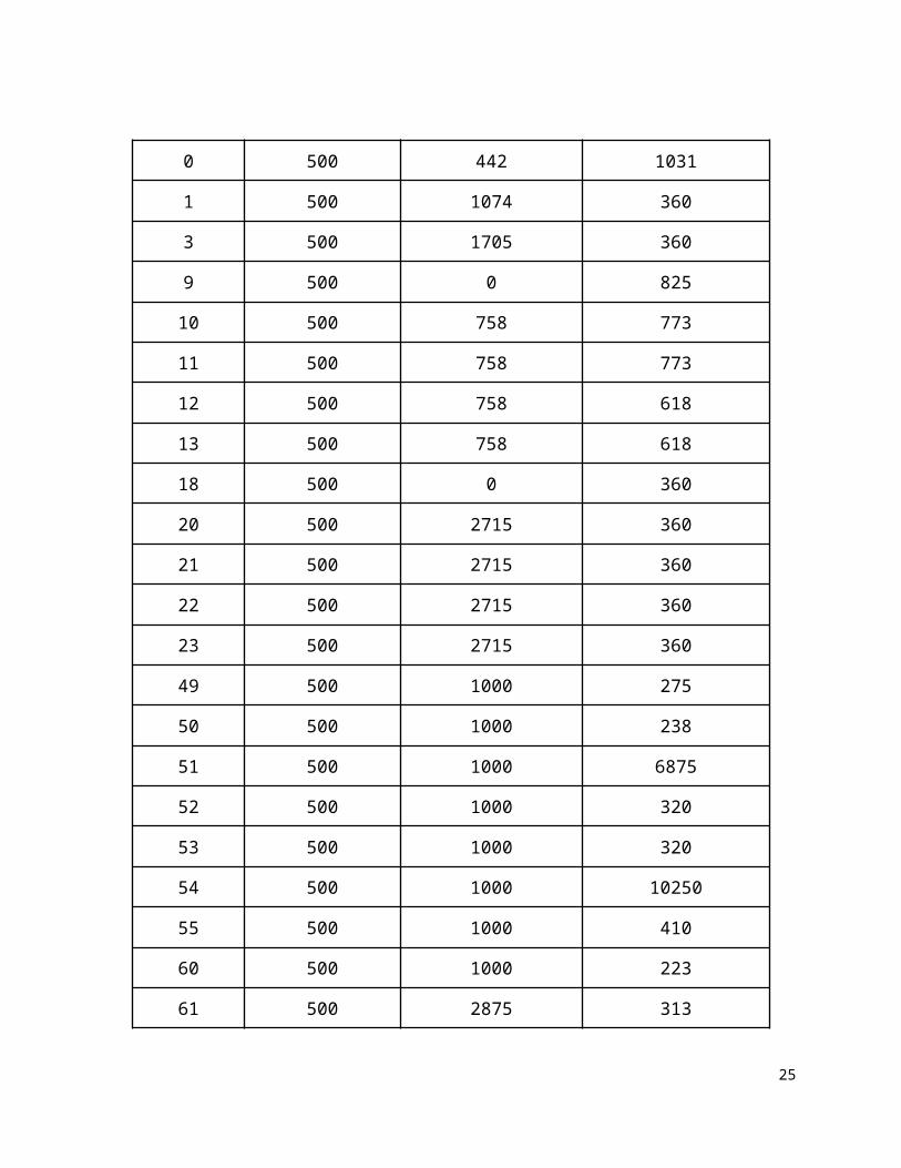
The full initial table of frame timing parameters to be used is as follows:
Frame Type Service Time (μs) Response Time (μs) Command Time (μs)
0 500 442 1031
1 500 1074 360
3 500 1705 360
9 500 0 825
10 500 758 773
11 500 758 773
12 500 758 618
13 500 758 618
18 500 0 360
20 500 2715 360
21 500 2715 360
22 500 2715 360
23 500 2715 360
49 500 1000 275
50 500 1000 238
51 500 1000 6875
52 500 1000 320
53 500 1000 320
54 500 1000 10250
55 500 1000 410
20
60 500 1000 223
61 500 2875 313
62 500 1000 125
65 500 8110 500
66 500 0 825
67 500 469 313
Table 2 - Frame Timing Parameters
Figure 5 - TX Queue Structure
The TX Queue, described above in Figure 5, is sorted in the following manner:
● There is a table of frame TX structures indexed by TX frequency;● Each TX structure contains a pointer to a list of Request Frames to be TX’ed at
this frequency. A NULL pointer indicates there are no Request Frames scheduled at this frequency;
● Each list of Request Frames is sorted by Frame Number (type) order;
21
● Each TX structure contains information as to when (jiffies) the first frame in the pointed to list is to be TX’ed next;
● The FIO_HZ_0 list (non-scheduled Request Frames) contains a complete list of all possible Request Frames;
● When the FIOMAN requires communications with an FIOD, a list of Request Frames to be queued is generated (from the FIO_HZ_0 list);
● All Request Frames in this list are sorted into the appropriate frequency list, in the correct sort order;
● The TX Timer Task sends all Request Frames of a given Frequency as a group;● The TX Timer Task sends Request Frames in lowest frequency to highest
frequency order. In so doing, this ensures that Date / Time frames whose frequency is typically 1 Hz, are sent before a group of frames whose frequency is 10 Hz.
The TX Queue, described above, is sorted in the following manner:
● There is a table of frame TX structures indexed by TX frequency;● Each TX structure contains a pointer to a list of Request Frames to be TX’ed at
this frequency. A NULL pointer indicates there are no Request Frames scheduled at this frequency;
● Each list of Request Frames is sorted by Frame Number (type) order;● Each TX structure contains information as to when (jiffies) the first frame in the
pointed to list is to be TX’ed next;● The FIO_HZ_0 list (non-scheduled Request Frames) contains a complete list of
all possible Request Frames;● When the FIOMAN requires communications with an FIOD, a list of Request
Frames to be queued is generated (from the FIO_HZ_0 list);● All Request Frames in this list are sorted into the appropriate frequency list, in
the correct sort order;● The TX Timer Task sends all Request Frames of a given Frequency as a group;● The TX Timer Task sends Request Frames in lowest frequency to highest
frequency order. In so doing, this ensures that Date / Time frames whose frequency is typically 1 Hz, are sent before a group of frames whose frequency is 10 Hz.
When the FIOMSG TX Timer Task fires, the next Request Frame in the TX Queue (as mentioned above) is sent on the indicated port to the indicated FIOD. Before the actual TX occurs, however, the FIOMSG TX Timer Task invokes the FIOMAN “Last Chance to Update” call back routine; as described above. This allows the FIOMAN to ensure the correct information is conveyed to the FIOD.
When a Request Frame is sent from the TX Queue, the next TX time is established. This is done to make sure TX time drift does not occur. The new TX time is the current time (jiffies) plus the Request Frame transmission frequency HZ.
If the Request Frame being TX’ed is expecting a Response Frame, a RX Timer Task is
22
set up; based upon the expected full Response Time from the NEMA TS2 Table. When the RX Timer Task fires; the Response Frame is expected to be fully received by the manufacture supplied SDLC Device Driver. A read is performed to the manufacture supplied SDLC Device Driver. If no data is available, the response is marked in error (no response). If a Response Frame is found, error checking is performed it ensure that the expected Response Frame is what was received. If the correct Response Frame was received, it is added to the RX List and the correct FIOMAN RX call back routine is invoked to allow the FIOMAN to cache information as needed.
The RX List is a table sorted by FIOD. For each FIOD, the last Response Frame per frame type is maintained in frame number (type) order. There is one RX List per port.
23
4 FPUI API DESIGN VIEWS
The following design views show decomposition, dependency, interface and detail aspects of the proposed design for the Front Panel User Interface API reference implementation. This design is intended to meet the general requirements of allowing multiple application programs to share access to the Front Panel resource of the ATC platform, and providing a set of utility screens to allow a standard configuration interface to any ATC unit.
4.1 FPUI API Decomposition Description
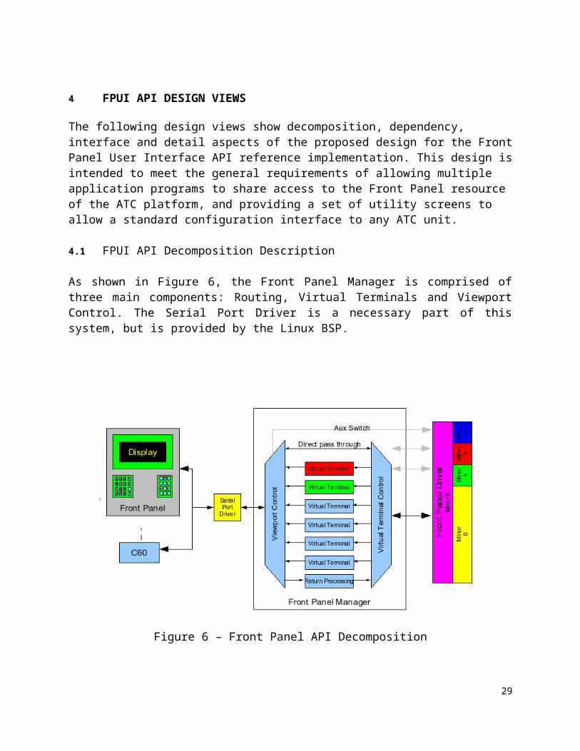
As shown in Figure 6, the Front Panel Manager is comprised of three main components: Routing, Virtual Terminals and Viewport Control. The Serial Port Driver is a necessary part of this system, but is provided by the Linux BSP.
Figure 6 – Front Panel API Decomposition
4.2 FPUI API Dependency DescriptionThe FrontPanelDriver entity is a Linux kernel driver module and depends on the Linux kernel itself for system level services, in particular queuing facilities.
The FIOAPI Library functions depend on the interfaces of FrontPanelDriver.
24
The ViewportControl entity of the Front Panel Manager process depends on the serial port device interface to the Front Panel Display hardware.
VirtualTerminal entity depends on ViewportControl to copy virtual display elements to the physical Front Panel Display.
4.3 FPUI API Interface Description
The FPUI driver kernel level module is a standard Linux compatible driver in every way except that it does not attach to any specific hardware component. It is designed to recognize five specific minor numbers, each representing different restrictions on the interface. As each interface is opened, including up to 16 opens on minor 0, a read queue is initialized. Data written to the driver is stored until the application attached to the destination interface can read it out. At this time there are no limits on the number of read messages that can be held by each open device, it is assumed that processes will be able to continuously read from their queues in order to keep them from growing too large. Any messages sent to devices not yet open will be dropped and not recovered by the system. Restrictions may be implemented at a later time.
To manage interfaces, the driver contains an array of interface description structures, one for each possible interface (currently 20). Each open passes in a unique file descriptor structure. This same structure is also passed in for reads, writes, ioctls, polls and releases. We use the private_data reference field of this structure to hold a reference to the interface description structure associated with the interface being opened. This provides all the necessary information required to ensure that data is properly routed between multiple interfaces. To ensure the ability to move between the file descriptor and the device descriptor, a copy of the reference to the file descriptor is also kept in the device descriptor structure. All accesses to these devices are through the open, close, read, write and ioctl system calls. Additional restrictions on each interface are discussed in the following sections.
4.3.1 General Application InterfaceMinor 0 is the general interface to the Virtual Windowing system. All applications should use this interface. This interface allows for up to 16 exclusive opens at any time. Applications may open more than one Virtual Terminal, but a single virtual Terminal will never be returned to more than one application. If different applications are required to share a common Virtual Terminal, they must share the file descriptor at a higher level. This interface also supports one Ioctl command to provide a registration string to the Master Selection Manager.
4.3.2 Direct InterfaceThe O_DIRECT flag is used to associate a direct interface with a window, backed by a virtual terminal to control its focus. When data is written to this interface and its associated window is in focus, the data is passed directly to the display. When the window is not in focus, the write blocks unless the O_NONBLOCK flags was asserted when opened. In this case the write will return the EAGAIN error code.
25
In general, reads will complete as long as there is pending data associated with that interface. If the direct interface was opened for reading, data comes directly from the display and keypads as long as the associated window is in focus. Once pending data is exhausted the read will block unless the O_NONBLOCK flag was asserted when opened. In this case the read will return the EAGAIN error code.
4.3.3 Master Selection Manager InterfaceMinor 1 is reserved for the Master Selection Manager. This manager controls and maintains the Front Panel Manager Window, which is presented to the user for selection of application focus. From this window, operators may select to view windows from other applications or select the system configuration window. Normal applications will not be allowed to open or use this interface. In addition, Viewport Control knows to route certain sequences of keystrokes directly to this window and to respond to requests from this window, regardless of focus. The Master Selection Window is an integral part of the Front Panel System, but it executes as an independent process within the operating environment.
4.3.4 System Configuration Manager InterfaceMinor 2 is reserved for the system configuration controller. The only entry into this window is from the Front Panel Manager Window, and the only exit is back to the Front Panel Manager Window. Again, normal applications are not allowed to access this interface. The process controlling the configuration is not part of the Front Panel System. It executes very much like any other application, but with elevated privilege.
When one of the first three devices is opened, a Virtual Terminal is created. This object persists until the device is closed. Applications using device 0 must also register a title for their application so that the Master Selection Manager can make the application Virtual Terminal available for selection and viewing. The remaining devices do not have a Virtual Terminal associated with them.
4.3.5 AUX Switch InterfaceMinor 3 provides access to the AUX Switch located on the front panel. This interface allows exclusive read only access to one process at a time. Once a process has successfully opened this interface, any other application wishing to acquire this interface must wait until the process currently holding the interface releases it. This interface allows for two modes of operation. If the interface is opened without the O_NONBLOCK asserted, a read operation will block until there is a change in the state of the AUX Switch. In this case poll and select can be used to determine if there has been a change in the state of the switch. If the interface is opened with the O_NONBLOCK flag asserted, read requests will complete immediately, returning the current state of the switch. In this mode, poll and select will always indicate that read data is ready. Since this is a read only interface, asserting O_RDWR or O_WRONLY while opening the interface as well as any attempt to write to the interface will return an error.
26
4.3.6 Front Panel Manager InterfaceMinor 8 is reserved for the Front Panel Manager. This is the interface that the other interfaces communicate with. Requests from applications are received on interfaces 0 through 4 and preprocessed according to the restrictions of the specific interface they were received on. The resulting message is loaded into a queue for the Front Panel Manager to read, using this interface. Responses and key strokes for applications with focus are received by this interface and processed. The resulting information is then loaded to the read queue of the specific application it was intended for. Write requests on one interface always translate to read buffers on another interface.
4.4 FPUI API Detailed Design
4.4.1 RoutingThis process handles dissemination of data packets from the Front Panel Driver. It either acts on them directly, or it sends them to the appropriate Virtual Terminal. In addition, it must channel incoming data from the keypad back to the proper application. It is also responsible for creating and destroying Virtual Terminals as applications open and close the Front Panel Driver, and for handling any system level control operations.
Communication between the Front Panel Driver and the Front Panel Manager Daemon is handled through an exclusive interface in the driver. Each message wrapped with a header that indicates its source and destination device, and its general operation. The source is used to route the messages to the proper virtual terminal or back to the proper process. Data type messages are passed on to the selected virtual terminal for parsing. Create and Destroy messages create or destroy the entire virtual terminal for the requesting device. Focus messages request the focus of the physical front panel devices be given to the specified virtual terminal. All other message types are ignored. State changes of the AUX switch and requests for the current state of the AUX switch bypass any Virtual Terminal and are passed directly between Viewport Control and Routing.
4.4.2 Virtual TerminalThis process handles the specific needs of the individual window it manages. It interprets the incoming X3.64 escape sequences and character strings which it uses to update and manage the memory resident virtual terminal. Screen and character attributes are stored along with the virtual display to ensure that the screen can be accurately reproduced on the physical display device when it is granted focus. Requests for attribute, state or status information are returned to the Virtual Window Controller for routing back to the proper process. When created, virtual terminals are defined to be the size of the attached physical display, or 8x40 if no display is currently attached.
Each virtual terminal also holds a 16 entry map for incoming escape sequences. When an escape sequence is returned from the display, it is compared to the entries in the map. If a match is found, the entire escape sequence is replaced with the single byte
27
key value associated with that escape sequence. If the escape sequence is not found in the map, then the sequence is passed on to the application in focus unaltered.
In order to support the direct interface, the virtual terminal actually returns two sequences, the mapped sequence and the original sequence. These are queued by the appropriate interface, if it has been opened for reading, otherwise it is discarded.
In addition to the 16 possible virtual terminals assigned to application processes, there are two additional virtual terminals, which are reserved for system managers. The first is the Master Selection Window. From this window, focus can be given to the various applications currently registered. Only from this window can one get to the second system window, reserved for System Configuration. To avoid confusion, the Front Panel Driver has implemented two additional minor interfaces for these windows. By changing the minor number of the device, the Front Panel Driver can isolate and restrict accesses through these interfaces to the appropriate window.
4.4.3 Viewport ControlThis process has responsibility for selecting which Virtual Terminal gets focus and setting up the attributes for that window. It also must interpret and convert the contents of the virtual terminal into standard X3.64 escape sequences such that the physical display will accurately represent the contents of the virtual terminal. Finally, it must keep the physical window synchronized with the virtual terminal while that window has focus. On the input side, it receives key strokes from the keypads and checks them for special sequences on which it acts. All other sequences are forwarded on and eventually back to the process currently in focus. In addition it will signal both the application loosing focus and the one gaining focus. The application must decide whether or not to listen for this signal and how to respond to it.
Viewport Control recognizes only three special key sequences. The keystrokes “**<ENT>” will always bring the Master Selection window back into focus. The <ESC>OT and <ESC>OU escape sequences from the AUX Switch are interpreted and sent directly to the AUX driver interface. All other key sequences are passed through to the Virtual Terminal that is currently in focus. Special key stroke sequences must be entered with no more than a 1 second delay between each character or the sequence will not be recognized and the characters forwarded on to the listening application.
Viewport Control also has the responsibility of determining if the front panel hardware had been altered. To do this it sends an inquiry to the display every 5 seconds and expects a response back within 1 second. If it receives the response it assumes that the display is present and unaltered. If there is no response it assumes that the display is missing (or defective). The polling routine specifically looks for transitions between present and missing. When the display goes missing, the community of registered applications is notified of a change. When the display appears, the poller first queries the size of the display and then notifies the registered applications. If the display size has changed, it is up to the applications to query the new screen size and redraw their screens appropriately.
28
4.4.4 Serial Port DriverThis section represents the standard Serial Port Device Driver, as provided by the Embedded OS distribution. There is no requirement at this time to modify or extend this driver. It is opened exclusively at system initialization by the Front Panel Manager and never released. All communications to and from the physical front panel display and keypad go through this driver.
4.4.5 Direct Pass ThroughIn order to support Graphical and any non-standard interface requirements, the driver provides a set of Direct Interfaces. There are 16 interfaces which are paired with the standard Application Interfaces. An application may open either or both interfaces for reading and/or writing. When opening this device, the O_NONBLOCK flag controls how reads and writes are handled when the applications window in not in focus. In normal mode (blocking mode) any attempt to read (when no data is pending) or write while the applications window is not in focus will cause the operation to block until the window gains focus. If the O_NONBLOCK flag was asserted during the open (non-blocking mode) any attempt to read or write while the applications window is not in focus will return the EAGAIN error code to indicate that the read or write cannot complete. When the applications window is in focus, reads and writes proceed normally. The poll and select methods can be used in blocking mode to determine if a subsequent read or write would block, prior to issuing those commands.
4.4.6 Master Selection Process
The Master Selection process is responsible for display and operation of the ATC Front Panel Manager Window as described in ATC5401 section 3.1.1.1. This process uses the minor 1 (/dev/msi) device of the FrontPanelDriver to interact with a virtual window provided by the VirtualTerminal handler, and to receive key press data along with other message types in order to correctly display and allow selection from the current list of registered application programs. The following message types are used:REGISTER - indicates that an application has registered with the front panel API and contains the application name as registered. If the application registering is the default application it is given focus (i.e. is shown on the physical display) automatically, otherwise it is listed as the next menu item. DESTROY - indicates that an application has ceased to be registered with the front panel API and contains the application name as registered. The application is removed from the menu item list.DATA - key press data received whilst the MasterSelection window is in focus.EMERGENCY - indicates that an application has submitted a request for focus be indicated to the user, or a cancellation of such.
This process maintains a configuration file “/etc/default/fpui” to persistently record the default application name.
29
4.4.7 System Configuration Process
The System Configuration process is responsible for display and operation of the ATC Configuration Window as described in ATC5401 section 3.2.1. This process uses the minor 2 (/dev/sci) device to interact with a virtual window provided by the VirtualTerminal handler. This process operates the menu and configuration screens’ navigation and editing functions as required and handles key press data received whilst the Configuration Window is in focus. The following configuration screens are maintained:
System Time: an update thread is started to display the current system time, timezone and daylight saving settings every second in the required fixed field locations. The time recorded at the moment of first display of this screen is shown in the required editable field locations. User key operations are handled as required, and any committed changes cause the system time, timezone and daylight saving settings of the operating system to be updated.
Ethernet Settings: an update thread is started to display the Ethernet adapter settings. The following Linux standard resources are used in relation to the settings presented: “/sys/class/net/eth0/address”, “/sys/class/net/eth1/address” (adapter Ethernet address); “/etc/network/interfaces” (mode, IP address, netmask); “/proc/net/route” (default gateway); “/etc/resolv.conf” (DNS server); “/proc/sys/kernel/hostname” (hostname); “/proc/net/dev” (packet statistics). User key operations are handled as required, and any committed changes are enacted both dynamically and persistently by modification of the operating system resources.
System Services: an update thread is started to display the System Services configuration screen. The following Linux conventional resources are used in relation to the settings presented: init scripts located in the “/etc/init.d” directory. Scripts named with a preceding ‘S’ character are treated as enabled. Scripts disabled by this configuration utility are renamed with a preceding ‘X’ character.
Linux Information: an update thread is started to display the Linux information. The following Linux standard resources are used: uname() system call (kernel release, kernel version, machine hardware); sysinfo() system call (total RAM, uptime, load average).
API Information: the API information is displayed in the required format and obtained by use of the following API library functions: fpui_apiver(); fio_apiver(); tod_apiver().
Host EEPROM Content: an update thread is started to display the Host EEPROM content in the required format. The underlying resource used is the “/dev/eeprom” device from the ATC5201 Standard BSP.
30
4.4.8 FPUI API Library
The library containing the full list of functions described in ATC5401 section 4.1 provides application programs with convenient means of implementing a front panel interface at a level abstracted from the detail of the device driver interface and escape sequence encoded commands and responses.
fpui_open() : performs an open() call to the minor 0 (/dev/fpi) device to obtain a file handle used for further interaction with the Front Panel Manager system; performs a REGISTER ioctl call to the same device which causes the application to be registered with name passed parameter.
fpui_close() : performs a close() call on the file handle passed parameter, causing the associated window resources to be released, and the application registered name to be removed from selection.
Details of the remaining library calls listed below, are found in the ATC5401 API Standard section 4.1.fpui_apiver();fpui_clear();fpui_refresh();fpui_get_window_size();fpui_get_focus();fpui_set_emergency();fpui_open_config_window();fpui_close_config_window();fpui_set_window_attr();fpui_get_window_attr();fpui_set_character_blink();fpui_get_character_blink();fpui_set_backlight();fpui_get_backlight();fpui_set_backlight_timeout();fpui_set_cursor_blink();fpui_get_cursor_blink();fpui_set_reverse_video();fpui_get_reverse_video();fpui_set_underline();fpui_get_underline();fpui_set_auto_wrap();fpui_get_auto_wrap();fpui_set_auto_repeat();fpui_get_auto_repeat();fpui_set_cursor();fpui_get_cursor();
5 TOD API DESIGN VIEWSThe following design views show decomposition, dependency, interface and detail aspects of the proposed design for the Time-of-day API reference implementation. This design is intended to meet the general requirement of allowing multiple application programs to share access to the timekeeping and calendar/clock resources of the ATC platform.
5.1 TOD API Decomposition Description
The TOD API library provides a higher level interface to the capabilities of the Linux timekeeping system and the time-of-day driver provided by the ATC Controller BSP. The library layer functions are sub-divided into three main areas: time set/get functions; daylight saving time functions; time source and signalling functions.Time source and signalling functionality is further broken down into: functionality related to internal time sources; functionality related to external time sources.
5.2 TOD API Dependency Description
Time set/get functions and daylight saving time functions of the TOD API library depend on the C standard library function “localtime()”, and the global variables “timezone” and “daylight”. These standard library functions depend, in turn, on the TZif2 format file “/etc/localtime”, accessible from the ATC Linux filesystem, for persistent and global storage of the timezone and local daylight saving rules.
Time source and signalling functions which relate to internal time sources depend on the time-of-day device driver “/dev/tod” provided by the ATC Linux BSP.
Time source and signalling functions which relate to external time sources depend on the programs and configuration files of the ntpd service.
5.3 TOD API Interface Description
The functions of the TOD API library provide the application level interface.
The time-of-day driver from the ATC Controller BSP provides the following low-level interface for use by the the TOD API library function implementation:
The following C standard library functions and global variables, available from the ATC Linux platform, facilitate the time-of-day, timezone and daylight-saving-time functionality: localtime(), timezone, daylight.
The following Linux standard programs and their associated configuration files facilitate the configuration of ‘external’ time sources: ntpd (Network Time Protocol Daemon), ldattach (Linux line discipline attach utility).
5.4 TOD API Detailed Design
5.4.1 Time Set/Get Functions
These functions take the passed parameters of the API function prototype and by making use of the appropriate time-related Linux system calls, enact the required functionality.
tod_get()
Obtain UTC timestamp as type “struct timeval” using gettimeofday(); Update “timezone” and “daylight” global variables by call to tzset(); Adjust “struct timeval” to local time with offset calculated from “timezone” and
“daylight”;
tod_set() subtract tzsec_offset parameter from tv parameter and call settimeofday()
passing result; modify file “/etc/localtime” by creating a TZif2 format entry from tzsec_offset
parameter;
5.4.2 Daylight Saving Time (DST) Functions
These functions take the passed parameters of the API function prototype and by making use of the appropriate time-related Linux system calls, C library variables and the TZif2 format files and access functions, enact the required functionality.
tod_set_dst_state()
Modifies the file “/etc/localtime” TZif2 format entry according to state of “enabled” parameter
tod_get_dst_state() Calls tzset() to update “daylight” global variable and set return value accordingly
tod_get_dst_info() Reads the TZif2 format entry from file “/etc/localtime”; Populates the “dst_info_t” structure from the TZif2 format entry;
34
tod_set_dst_info() Creates a TZif2 format entry from the “dst_info_t” structure parameter;
write the TZif2 format entry to file “/etc/localtime”
5.4.3 Time Source and Signaling FunctionsThese functions take the passed parameters of the API function prototype and by making use of the appropriate ioctl interface of the time-of-day driver “/dev/tod” from the ATC Linux BSP, enact the required functionality.
tod_get_timesrc(): Performs an ioctl system function call with command parameter
ATC_TOD_GET_TIMESRC, returning the result
tod_set_timesrc(): When passed enumeration TOD_TIMESRC_LINESYNC, performs an ioctl
system function call with command parameter ATC_TOD_SET_TIMESRC and with argument parameter ATC_TIMESRC_LINESYNC
When passed enumeration TOD_TIMESRC_RTCSQWR, performs an ioctl system function call with command parameter ATC_TOD_SET_TIMESRC and with argument parameter ATC_TIMESRC_RTCSQWR
When passed enumeration TOD_TIMESRC_CRYSTAL, performs an ioctl system function call with command parameter ATC_TOD_SET_TIMESRC and with argument parameter ATC_TIMESRC_CRYSTAL
When passed enumeration TOD_TIMESRC_EXTERNAL1, performs an ioctl system function call with command parameter ATC_TOD_SET_TIMESRC and with argument parameter ATC_TIMESRC_CRYSTAL, then performs configuration of NTP reference clock driver 127.127.20.0 for NMEA GPS devices
When passed enumeration TOD_TIMESRC_EXTERNAL2, performs an ioctl system function call with command parameter ATC_TOD_SET_TIMESRC and with argument parameter ATC_TIMESRC_CRYSTAL, then performs configuration of NTP host server.
tod_get_timesrc_freq(): Performs an ioctl system function call with command parameter
ATC_TOD_GET_INPUT_FREQ, returning the result
tod_request_tick_signal(): Performs an ioctl system function call with command parameter
ATC_TOD_REQUEST_TICK_SIG
tod_cancel_tick_signal(): Performs an ioctl system function call with command parameter
ATC_TOD_CANCEL_TICK_SIG
tod_request_onchange_signal():35
Performs an ioctl system function call with command parameter ATC_TOD_REQUEST_ONCHANGE_SIG
tod_cancel_onchange_signal(): Performs an ioctl system function call with command parameter
ATC_TOD_CANCEL_ONCHANGE_SIG
36
6 REQUIREMENTS TRACEABILITY
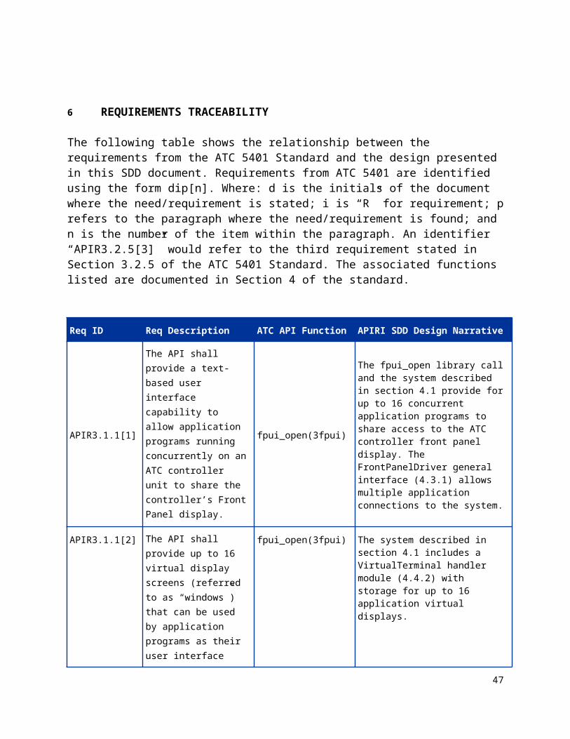
The following table shows the relationship between the requirements from the ATC 5401 Standard and the design presented in this SDD document. Requirements from ATC 5401 are identified using the form dip[n]. Where: d is the initials of the document where the need/requirement is stated; i is “R” for requirement; p refers to the paragraph where the need/requirement is found; and n is the number of the item within the paragraph. An identifier “APIR3.2.5[3]” would refer to the third requirement stated in Section 3.2.5 of the ATC 5401 Standard. The associated functions listed are documented in Section 4 of the standard.
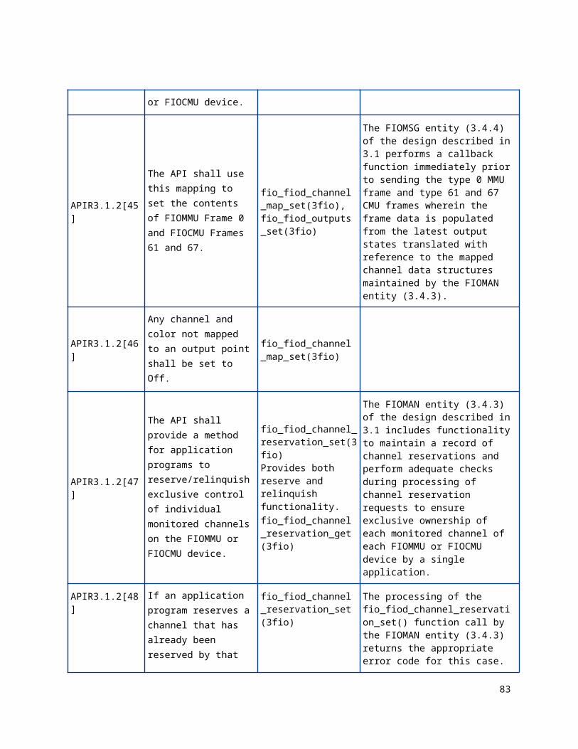
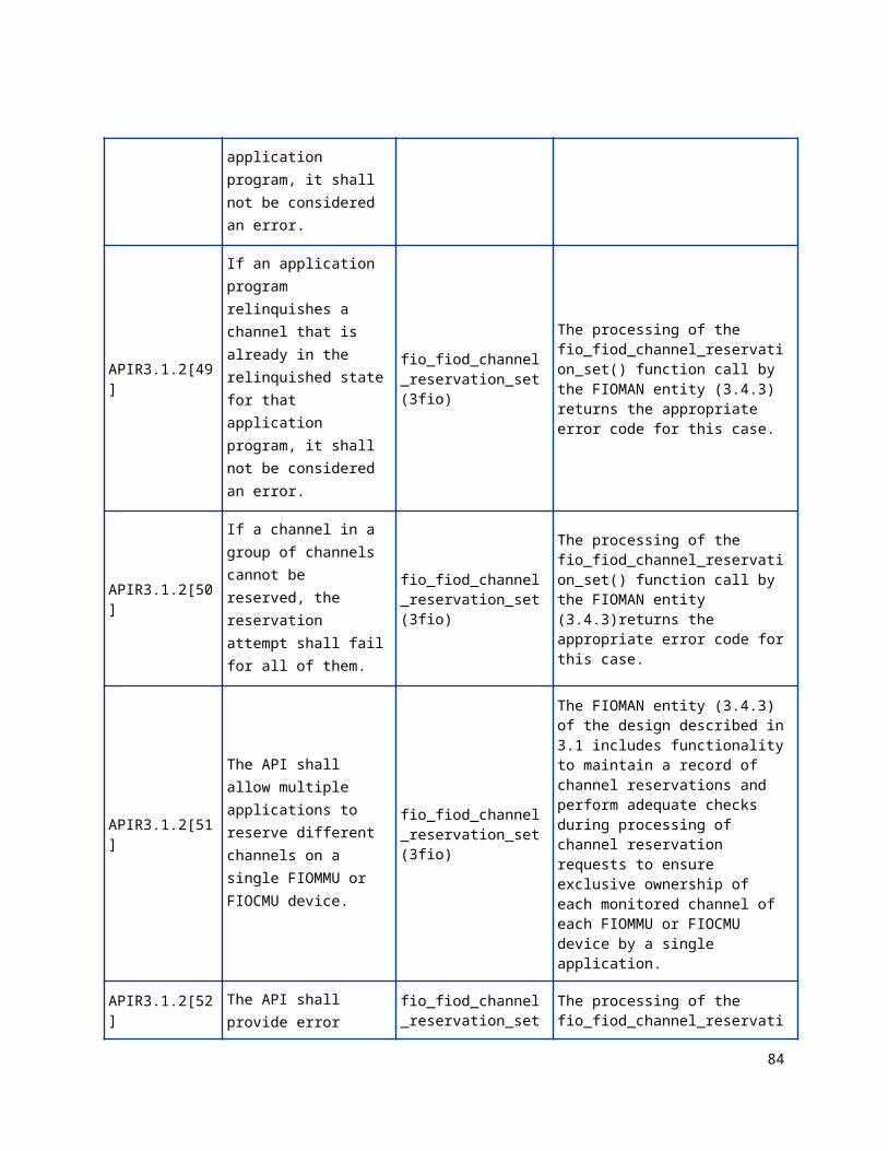
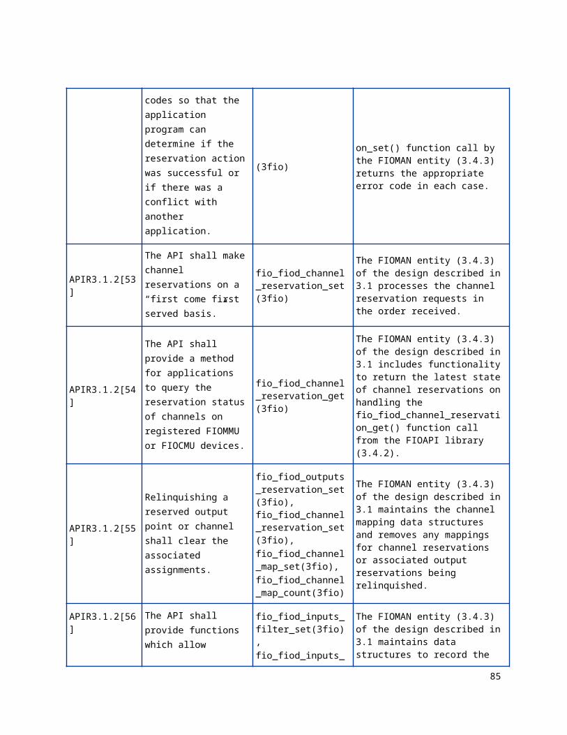
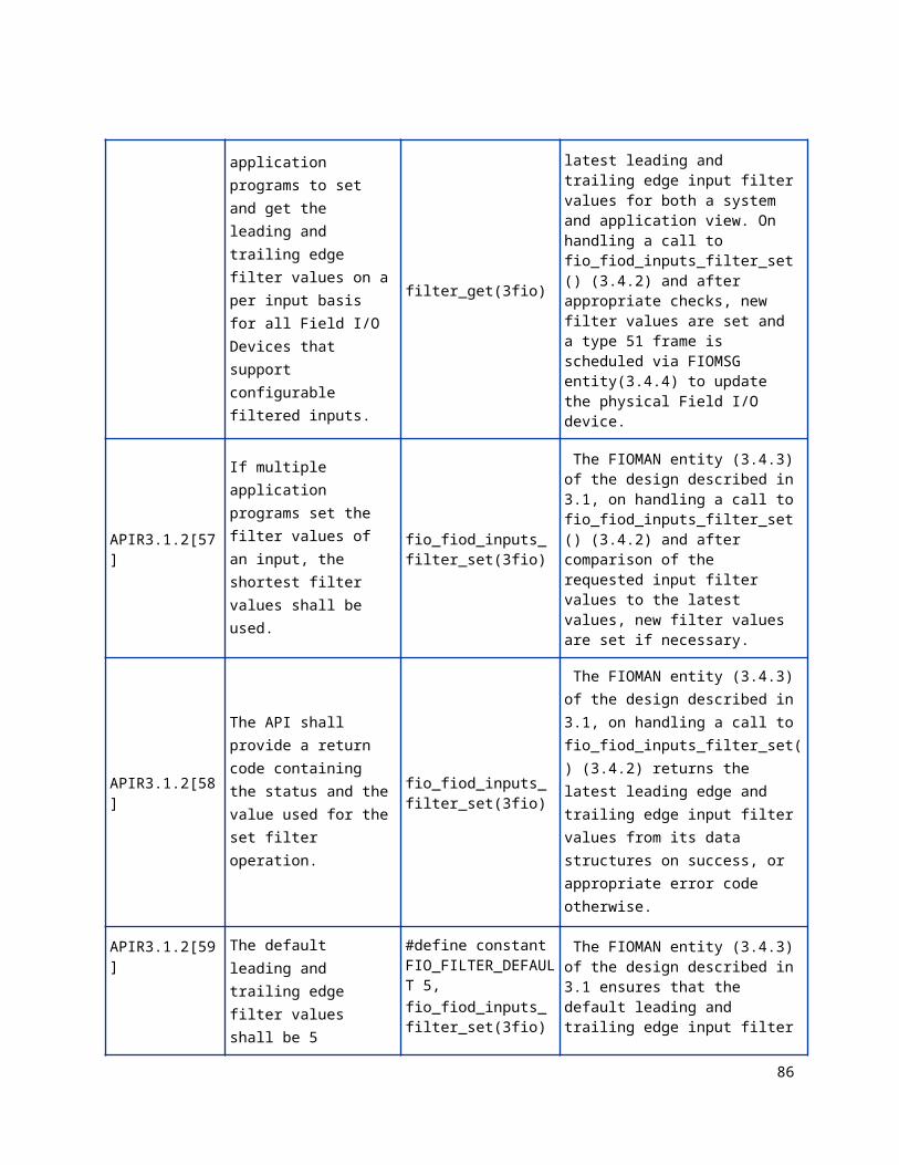
Req ID Req Description ATC API Function APIRI SDD Design Narrative
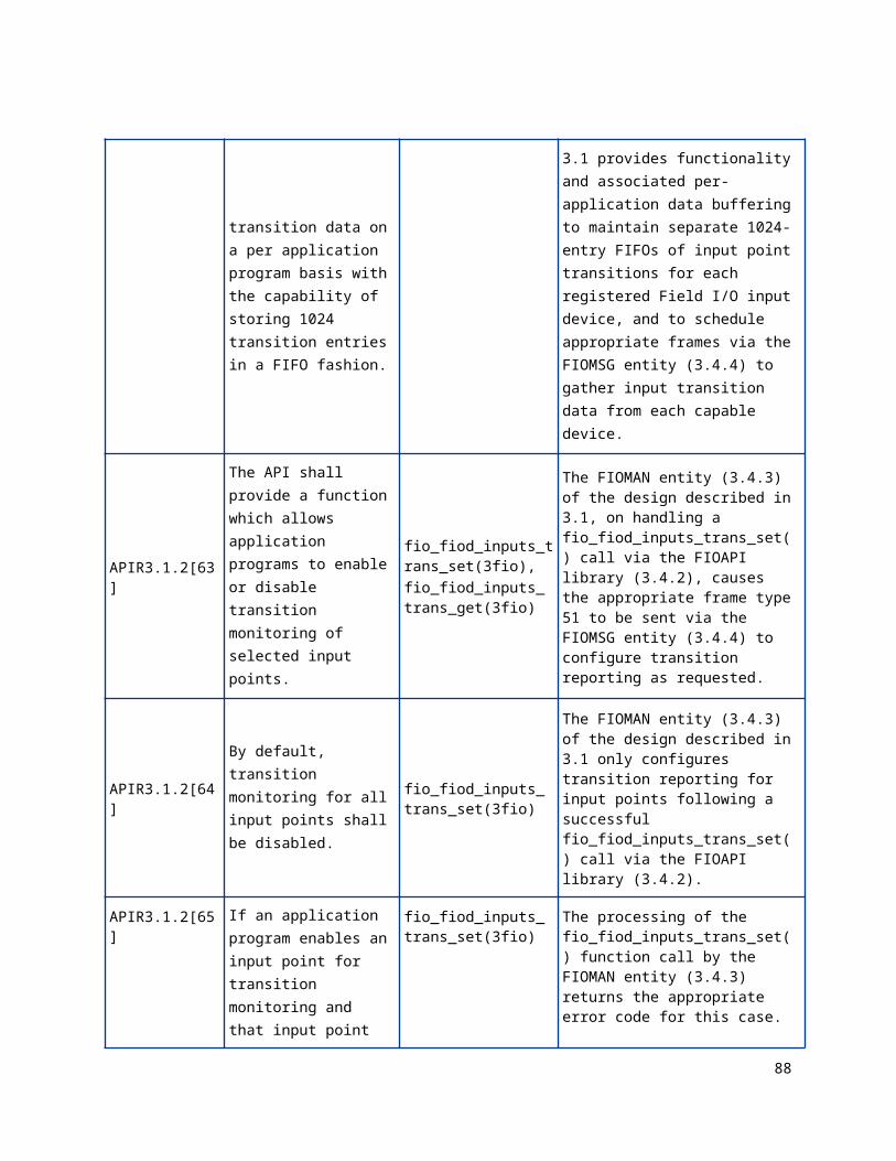
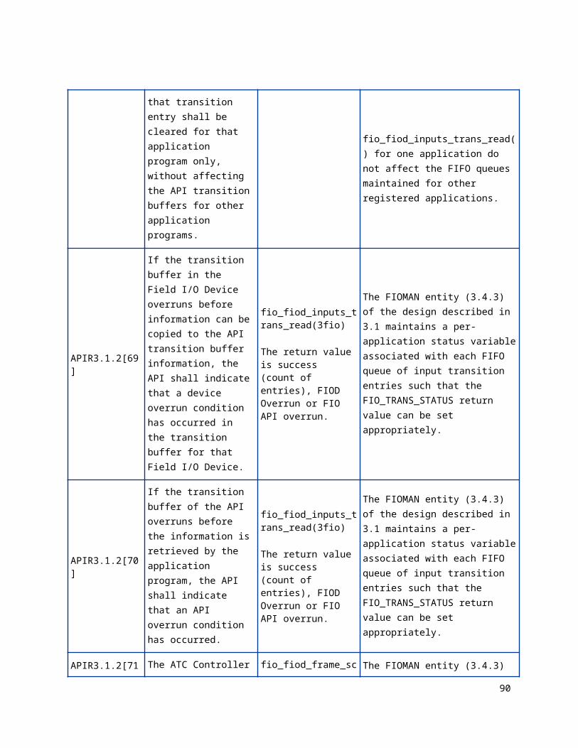
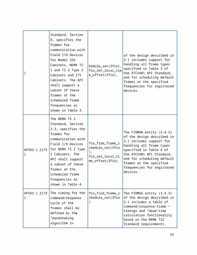
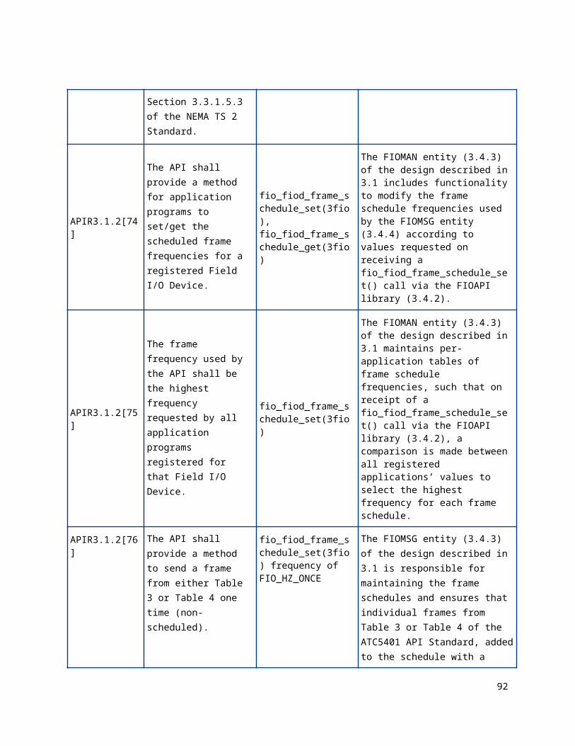
APIR3.1.1[1]
The API shall provide a text-based user interface capability to allow application programs running concurrently on an ATC controller unit to share the controller’s Front Panel display.
fpui_open(3fpui)
The fpui_open library call and the system described in section 4.1 provide for up to 16 concurrent application programs to share access to the ATC controller front panel display. The FrontPanelDriver general interface (4.3.1) allows multiple application connections to the system.
APIR3.1.1[2]
The API shall provide up to 16 virtual display screens (referred to as “windows”) that can be used by application programs as their user interface display.
fpui_open(3fpui)
The system described in section 4.1 includes a VirtualTerminal handler module (4.4.2) with storage for up to 16 application virtual displays.
APIR3.1.1[3]
The display size of the windows shall be equal to the physical display size (lines x characters) of the controller’s Front Panel display (if one exists).
fpui_open(3fpui)
The system described in 4.1 includes a ViewportControl process (4.4.3) which attempts to obtain the dimensions of the physical display on startup or on detection of a display reconnection. The VirtualTerminal handler module (4.4.2) creates virtual displays sized according to the dimensions of the physical display if attached, or 8x40 if not.
APIR3.1.1[4] The display size of the windows shall have a minimum size of 4 lines x 40 characters and a
fpui_open(3fpui) The application virtual display storage of the VirtualTerminal handler module (4.4.2) is sized to represent a maximum display size
37
maximum size of 24 lines x 80 characters. of 24 rows of 80 columns.
APIR3.1.1[5]
If no physical display exists, the API shall operate as if it has a display with a size of 8 lines x 40 characters.
fpui_open(3fpui)
The system described in 4.1 includes a ViewportControl process (4.4.3) which attempts to obtain the dimensions of the physical display on startup or on detection of a display reconnection. The VirtualTerminal handler module (4.4.2) creates virtual displays sized according to the dimensions of the physical display if attached, or 8x40 if not.
APIR3.1.1[6]Only one window shall be displayed at a time on the Front Panel display.
fpui_open(3fpui)
The system described in 4.1 includes a ViewportControl process (4.4.3) which keeps track of which virtual display shall have focus, and thus be the only window displayed to the physical display.
APIR3.1.1[7]
When a window is displayed, the API shall display the character representation of the window on the Front Panel display (if one exists).
fpui_open(3fpui)
The system described in 4.1 includes a VirtualTerminal handler (4.4.2) which maintains the character representation for each window (virtual display). When a window is selected for display (focused) the virtual display is also copied to the physical display.
APIR3.1.1[8]
The application program associated with the window displayed shall receive the characters input from the Front Panel input device (Ex. keyboard or keypad).
fpui_open(3fpui)
The system described in 4.1 includes a ViewportControl process (4.4.3) which routes the characters received on the Front Panel input device to the application whose window has focus via the Routing process (4.4.1) and the FrontPanelDriver interface (4.3.1) held open by the application.
APIR3.1.1[9]
The API shall support the display character set as defined in the ATC Controller Standard, Section 7.1.4.
fpui_open(3fpui)
The system described in 4.1 includes a VirtualTerminal handler (4.4.2) whose display character set matches that of the latest ATC Controller Standard.
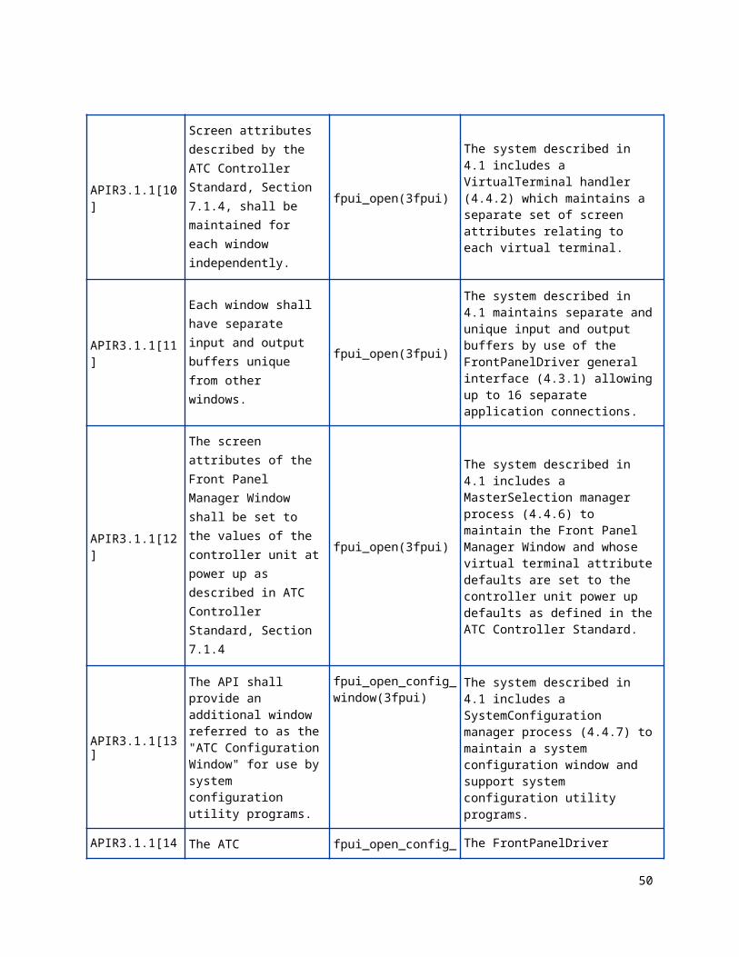
APIR3.1.1[10] Screen attributes described by the ATC Controller Standard, Section 7.1.4, shall be maintained for each
fpui_open(3fpui) The system described in 4.1 includes a VirtualTerminal handler (4.4.2) which maintains a separate set of screen attributes relating to each virtual terminal.
38
window independently.
APIR3.1.1[11]
Each window shall have separate input and output buffers unique from other windows.
fpui_open(3fpui)
The system described in 4.1 maintains separate and unique input and output buffers by use of the FrontPanelDriver general interface (4.3.1) allowing up to 16 separate application connections.
APIR3.1.1[12]
The screen attributes of the Front Panel Manager Window shall be set to the values of the controller unit at power up as described in ATC Controller Standard, Section 7.1.4
fpui_open(3fpui)
The system described in 4.1 includes a MasterSelection manager process (4.4.6) to maintain the Front Panel Manager Window and whose virtual terminal attribute defaults are set to the controller unit power up defaults as defined in the ATC Controller Standard.
APIR3.1.1[13]
The API shall provide an additional window referred to as the "ATC Configuration Window" for use by system configuration utility programs.
fpui_open_config_window(3fpui)
The system described in 4.1 includes a SystemConfiguration manager process (4.4.7) to maintain a system configuration window and support system configuration utility programs.
APIR3.1.1[14]
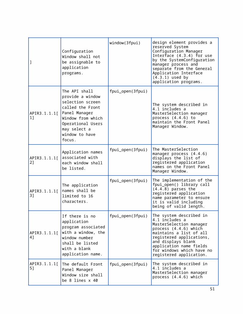
The ATC Configuration Window shall not be assignable to application programs.
fpui_open_config_window(3fpui)
The FrontPanelDriver design element provides a reserved System Configuration Manager Interface (4.3.4) for use by the SystemConfiguration manager process and separate from the General Application Interface (4.3.1) used by application programs.
APIR3.1.1.1[1]
The API shall provide a window selection screen called the Front Panel Manager Window from which Operational Users may select a window to have focus.
fpui_open(3fpui)The system described in 4.1 includes a MasterSelection manager process (4.4.6) to maintain the Front Panel Manager Window.
APIR3.1.1.1[2]Application names associated with each window shall be listed.
fpui_open(3fpui) The MasterSelection manager process (4.4.6) displays the list of registered application names on the Front Panel Manager Window.
APIR3.1.1.1[3] The application names shall be limited to 16 characters.
fpui_open(3fpui) The implementation of the fpui_open() library call (4.4.8) parses the registered application name parameter to ensure it is valid
39
including being of valid length.
APIR3.1.1.1[4]
If there is no application program associated with a window, the window number shall be listed with a blank application name.
fpui_open(3fpui) The system described in 4.1 includes a MasterSelection manager process (4.4.6) which maintains a list of all registered applications, and displays blank application name fields for windows which have no registered application.
APIR3.1.1.1[5]
The default Front Panel Manager Window size shall be 8 lines x 40 characters with the format as shown in Figure 7.
fpui_open(3fpui) The system described in 4.1 includes a MasterSelection manager process (4.4.6) which displays the Front Panel Manager window in the required default size and format.
APIR3.1.1.1[6]
If the Operational User has not set the default window, the Front Panel Manager Window shall be the default window.
N/A The system described in 4.1 includes a MasterSelection manager process (4.4.6) which displays the Front Panel Manager window if a default application window has not been set.
APIR3.1.1.1[7]
The default window shall be settable by the Operational User from the Front Panel Manager Window by pressing {*,[0-F],<ENT>}.
N/A The system described in 4.1 includes a MasterSelection manager process (4.4.6) which handles the key sequence to set the corresponding application window as the default.
APIR3.1.1.1[8]
The Operational User shall be capable of setting the default window to the Front Panel Manager Window by pressing {*,<ENT>} from the Front Panel Manager Window.
N/AThe system described in 4.1 includes a MasterSelection manager process (4.4.6) which handles the key sequence to set the Front Panel Manager window as the default.
APIR3.1.1.1[9]
The default window shall be designated by a star “*” character next to the window number.
N/A The system described in 4.1 includes a MasterSelection manager process (4.4.6) which displays the list of registered application names and indicates the default application with the “*” character, if set.
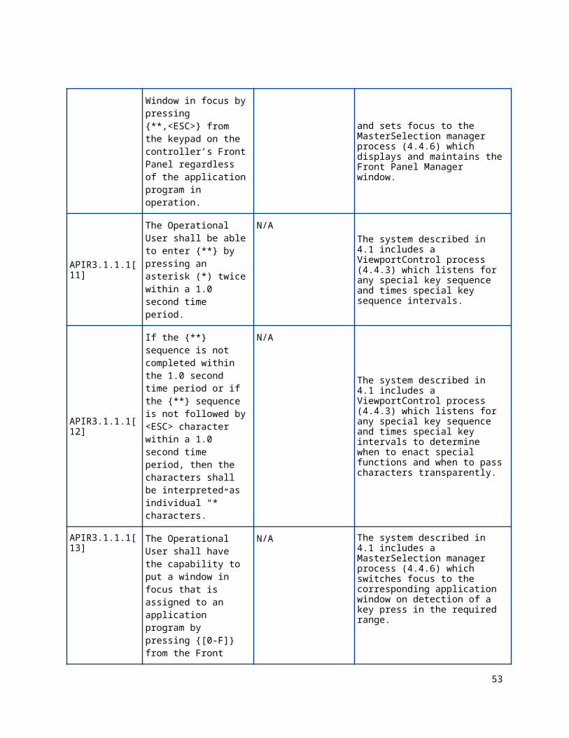
APIR3.1.1.1[10] The Operational User shall be able to put the Front Panel Manager Window in focus by pressing {**,<ESC>} from
N/A The system described in 4.1 includes a ViewportControl process (4.4.3) which listens for the special key sequence and sets focus to the MasterSelection manager process (4.4.6) which displays and
40
the keypad on the controller’s Front Panel regardless of the application program in operation.
maintains the Front Panel Manager window.
APIR3.1.1.1[11]
The Operational User shall be able to enter {**} by pressing an asterisk (*) twice within a 1.0 second time period.
N/A The system described in 4.1 includes a ViewportControl process (4.4.3) which listens for any special key sequence and times special key sequence intervals.
APIR3.1.1.1[12]
If the {**} sequence is not completed within the 1.0 second time period or if the {**} sequence is not followed by <ESC> character within a 1.0 second time period, then the characters shall be interpreted as individual “*” characters.
N/A
The system described in 4.1 includes a ViewportControl process (4.4.3) which listens for any special key sequence and times special key intervals to determine when to enact special functions and when to pass characters transparently.
APIR3.1.1.1[13]
The Operational User shall have the capability to put a window in focus that is assigned to an application program by pressing {[0-F]} from the Front Panel Manager Window.
N/AThe system described in 4.1 includes a MasterSelection manager process (4.4.6) which switches focus to the corresponding application window on detection of a key press in the required range.
APIR3.1.1.1[14]
The only possible window selections for focus from the Front Panel Manager Window shall be itself, the ATC Configuration Window, or a window assigned to an application program.
N/AThe system described in 4.1 includes a MasterSelection manager process (4.4.6) which is capable of switching focus to the system configuration window or a selected application window.
APIR3.1.1.1[15]
If the Front Panel Manager Window is the default window, no asterisk shall be displayed next to any application name in the Front Panel Manager Window.
N/AThe system described in 4.1 includes a MasterSelection manager process (4.4.6) which displays the list of registered applications with no “*” character if no application window is set as the default.
APIR3.1.1.1[16] The Operational User shall be able to put the ATC Configuration Window in focus by
N/A The system described in 4.1 includes a MasterSelection manager process (4.4.6) which responds to the {<NEXT>} key by
41
pressing {<NEXT>} in the Front Panel Manager Window.
switching focus to the System Configuration window.
APIR3.1.1.1[17]
The top two lines and bottom line of the Front Panel Manager Window shall be fixed as shown in Figure 7.
N/A The system described in 4.1 includes a MasterSelection manager process (4.4.6) which displays the Front Panel Manager window with the required top two lines and bottom line.
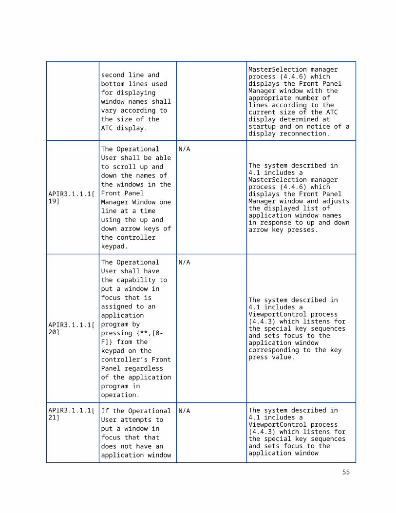
APIR3.1.1.1[18]
The number of lines between the second line and bottom lines used for displaying window names shall vary according to the size of the ATC display.
N/A The system described in 4.1 includes a MasterSelection manager process (4.4.6) which displays the Front Panel Manager window with the appropriate number of lines according to the current size of the ATC display determined at startup and on notice of a display reconnection.
APIR3.1.1.1[19]
The Operational User shall be able to scroll up and down the names of the windows in the Front Panel Manager Window one line at a time using the up and down arrow keys of the controller keypad.
N/AThe system described in 4.1 includes a MasterSelection manager process (4.4.6) which displays the Front Panel Manager window and adjusts the displayed list of application window names in response to up and down arrow key presses.
APIR3.1.1.1[20]
The Operational User shall have the capability to put a window in focus that is assigned to an application program by pressing {**,[0-F]} from the keypad on the controller’s Front Panel regardless of the application program in operation.
N/A
The system described in 4.1 includes a ViewportControl process (4.4.3) which listens for the special key sequences and sets focus to the application window corresponding to the key press value.
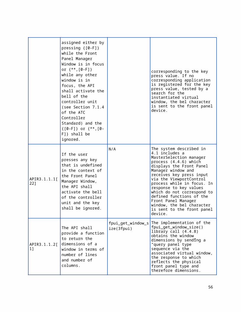
APIR3.1.1.1[21] If the Operational User attempts to put a window in focus that that does not have an application window assigned either by pressing {[0-F]} while the Front Panel Manager Window is in focus or {**,[0-F]} while any other window is in focus, the API shall activate the bell
N/A The system described in 4.1 includes a ViewportControl process (4.4.3) which listens for the special key sequences and sets focus to the application window corresponding to the key press value. If no corresponding application is registered for the key press value, tested by a search for the instantiated virtual window, the bel character is sent to the front panel device.
42
of the controller unit (see Section 7.1.4 of the ATC Controller Standard) and the {[0-F]} or {**,[0-F]} shall be ignored.
APIR3.1.1.1[22]
If the user presses any key that is undefined in the context of the Front Panel Manager Window, the API shall activate the bell of the controller unit and the key shall be ignored.
N/A The system described in 4.1 includes a MasterSelection manager process (4.4.6) which displays the Front Panel Manager window and receives key press input via the ViewportControl process while in focus. In response to key values which do not correspond to defined functions of the Front Panel Manager window, the bel character is sent to the front panel device.
APIR3.1.1.2[1]
The API shall provide a function to return the dimensions of a window in terms of number of lines and number of columns.
fpui_get_window_size(3fpui)
The implementation of the fpui_get_window_size() library call (4.4.8) obtains the window dimensions by sending a “query panel type” sequence via the associated virtual window, the response to which reflects the physical front panel type and therefore dimensions.
APIR3.1.1.2[2]
The API shall provide a function to open a window and register a name for display on the Front Panel Manager Window.
fpui_open(3fpui)
The implementation of the fpui_open() library call (4.4.8) allocates a virtual display via the VirtualTerminal handler (4.4.2) and allows an application to register a name for display on the Front Panel Manager Window via the MasterSelection manager process (4.4.6).
APIR3.1.1.2[3]
An application program shall be able to open multiple windows providing the windows resources are available.
fpui_open(3fpui)
The system described in section 4.1 includes a VirtualTerminal handler (4.4.2) that allows an application to register for one or more windows, following multiple calls to the fpui_open() library function (4.4.8).
APIR3.1.1.2[4]
The API shall provide the ability for an application program to reserve exclusive access to the Aux Switch (see ATC Controller Standard, Section 7.1.4).
fpui_open_aux_switch(3fpui),
The system described in section 4.1 includes the AuxSwitch interface to the FrontPanelDriver (4.3.5) which allows an application to reserve the aux switch for exclusive access via the fpui_open_aux_switch() library function (4.4.8).
APIR3.1.1.2[5] An application program N/A. The AuxSwitch interface to the
43
that has reserved exclusive access to the AUX Switch shall maintain exclusive access to the switch even if the application program has no window in focus.
FrontPanelDriver (4.3.5) makes use of a separate file context not associated with a virtual display, which may be used by an application independently from any virtual display association file context.
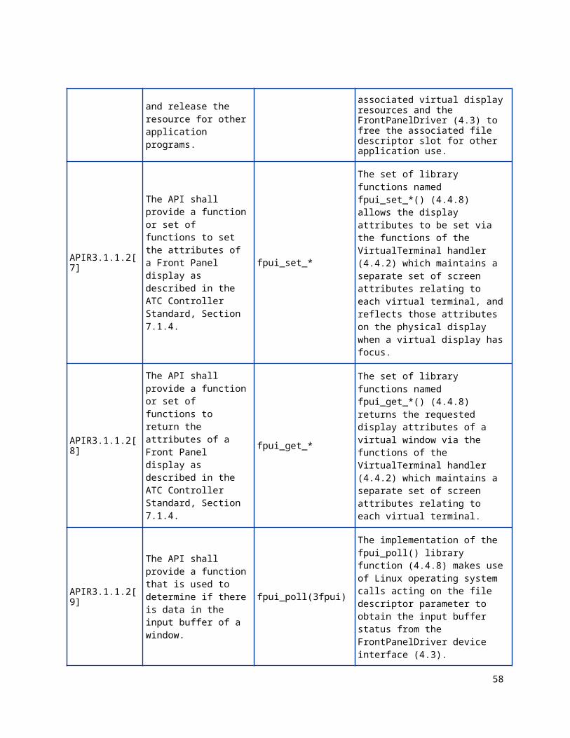
APIR3.1.1.2[6]
The API shall provide a function to close a window and release the resource for other application programs.
fpui_close(3fpui)
The fpui_close() library call (4.4.8) causes the VirtualTerminal handler (4.4.2) to release the associated virtual display resources and the FrontPanelDriver (4.3) to free the associated file descriptor slot for other application use.
APIR3.1.1.2[7]
The API shall provide a function or set of functions to set the attributes of a Front Panel display as described in the ATC Controller Standard, Section 7.1.4.
fpui_set_*
The set of library functions named fpui_set_*() (4.4.8) allows the display attributes to be set via the functions of the VirtualTerminal handler (4.4.2) which maintains a separate set of screen attributes relating to each virtual terminal, and reflects those attributes on the physical display when a virtual display has focus.
APIR3.1.1.2[8]
The API shall provide a function or set of functions to return the attributes of a Front Panel display as described in the ATC Controller Standard, Section 7.1.4.
fpui_get_*
The set of library functions named fpui_get_*() (4.4.8) returns the requested display attributes of a virtual window via the functions of the VirtualTerminal handler (4.4.2) which maintains a separate set of screen attributes relating to each virtual terminal.
APIR3.1.1.2[9]
The API shall provide a function that is used to determine if there is data in the input buffer of a window.
fpui_poll(3fpui)
The implementation of the fpui_poll() library function (4.4.8) makes use of Linux operating system calls acting on the file descriptor parameter to obtain the input buffer status from the FrontPanelDriver device interface (4.3).
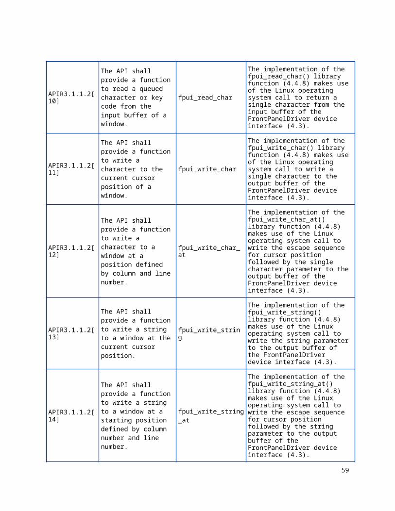
APIR3.1.1.2[10]
The API shall provide a function to read a queued character or key code from the input buffer of a window.
fpui_read_char
The implementation of the fpui_read_char() library function (4.4.8) makes use of the Linux operating system call to return a single character from the input buffer of the FrontPanelDriver device interface (4.3).
44
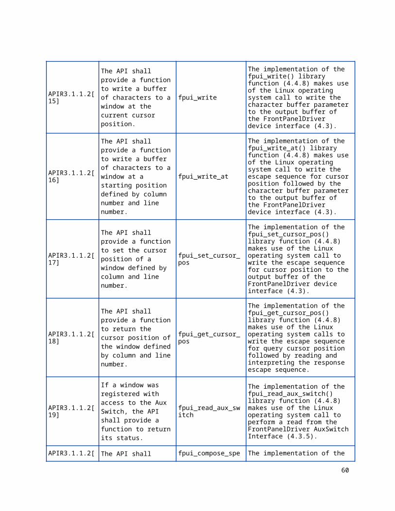
APIR3.1.1.2[11]
The API shall provide a function to write a character to the current cursor position of a window.
fpui_write_char
The implementation of the fpui_write_char() library function (4.4.8) makes use of the Linux operating system call to write a single character to the output buffer of the FrontPanelDriver device interface (4.3).
APIR3.1.1.2[12]
The API shall provide a function to write a character to a window at a position defined by column and line number.
fpui_write_char_at
The implementation of the fpui_write_char_at() library function (4.4.8) makes use of the Linux operating system call to write the escape sequence for cursor position followed by the single character parameter to the output buffer of the FrontPanelDriver device interface (4.3).
APIR3.1.1.2[13]
The API shall provide a function to write a string to a window at the current cursor position.
fpui_write_string
The implementation of the fpui_write_string() library function (4.4.8) makes use of the Linux operating system call to write the string parameter to the output buffer of the FrontPanelDriver device interface (4.3).
APIR3.1.1.2[14]
The API shall provide a function to write a string to a window at a starting position defined by column number and line number.
fpui_write_string_at
The implementation of the fpui_write_string_at() library function (4.4.8) makes use of the Linux operating system call to write the escape sequence for cursor position followed by the string parameter to the output buffer of the FrontPanelDriver device interface (4.3).
APIR3.1.1.2[15]
The API shall provide a function to write a buffer of characters to a window at the current cursor position.
fpui_write
The implementation of the fpui_write() library function (4.4.8) makes use of the Linux operating system call to write the character buffer parameter to the output buffer of the FrontPanelDriver device interface (4.3).
APIR3.1.1.2[16]
The API shall provide a function to write a buffer of characters to a window at a starting position defined by column number and line number.
fpui_write_at
The implementation of the fpui_write_at() library function (4.4.8) makes use of the Linux operating system call to write the escape sequence for cursor position followed by the character buffer parameter to the output buffer of the FrontPanelDriver device interface (4.3).
APIR3.1.1.2[17] The API shall provide a fpui_set_cursor_pos The implementation of the
45
function to set the cursor position of a window defined by column and line number.
fpui_set_cursor_pos() library function (4.4.8) makes use of the Linux operating system call to write the escape sequence for cursor position to the output buffer of the FrontPanelDriver device interface (4.3).
APIR3.1.1.2[18]
The API shall provide a function to return the cursor position of the window defined by column and line number.
fpui_get_cursor_pos
The implementation of the fpui_get_cursor_pos() library function (4.4.8) makes use of the Linux operating system calls to write the escape sequence for query cursor position followed by reading and interpreting the response escape sequence.
APIR3.1.1.2[19]
If a window was registered with access to the Aux Switch, the API shall provide a function to return its status.
fpui_read_aux_switch
The implementation of the fpui_read_aux_switch() library function (4.4.8) makes use of the Linux operating system call to perform a read from the FrontPanelDriver AuxSwitch Interface (4.3.5).
APIR3.1.1.2[20]
The API shall provide a function to compose special characters as described by the ATC Controller Standard, Section 7.1.4.
fpui_compose_special_char
The implementation of the fpui_compose_special_char() library function (4.4.8) makes use of the Linux operating system call to write the escape sequence with the special character definition buffer to the FrontPanelDriver device interface (4.3) which causes the VirtualTerminal handler (4.4.2) to store the special character definition in the corresponding virtual display and reflect such definitions to the physical display when the virtual display has focus.
APIR3.1.1.2[21] The API shall support the display of a composed character in the same manner as any other valid character.
fpui_display_special_char
The implementation of the fpui_display_special_char() library function (4.4.8) makes use of the Linux operating system call to write the “display special character” escape sequence along with the special character index number to the FrontPanelDriver interface (4.3) which causes the VirtualTerminal handler (4.4.2) to update the corresponding virtual display character position with an encoded value indicating the special character index number. When the corresponding virtual display gains
46
focus, the physical display is updated to show the indexed special character as previously defined.
APIR3.1.1.2[22]
The API shall provide a function to clear a window that operates on a window whether it is in or out of focus.
fpui_clear
The VirtualTerminal handler (4.4.2) includes functionality to handle the “clear screen” escape sequence and perform the operation on the virtual display regardless of focus.
APIR3.1.1.2[23]
The API shall provide a function to refresh a window that operates on a window whether it is in or out of focus.
fpui_refresh
The VirtualTerminal handler (4.4.2) includes functionality to refresh the physical display window from the virtual display both as required for changes to the virtual display and on request from the fpui_refresh() library call (4.4.8) while the virtual display has focus.
APIR3.1.1.2[24]
The bell of the controller’s Front Panel shall be activated only if a bell character, ^G (hex value 07), is sent from an application program which has a window that has focus.
N/A
The VirtualTerminal handler (4.4.2) includes functionality to only forward a bel character, received from an application, to the physical display when the application virtual display has focus.
APIR3.1.1.2[25]
If a bell character is sent from an application program that does not have a window that has focus, the bell character shall be ignored by the API.
N/A
The VirtualTerminal handler (4.4.2) includes functionality to ignore a bel character, received from an application, when the application virtual display does not have focus.
APIR3.1.1.2[26]
The API shall allow application programs to illuminate or extinguish the backlight of the ATC controller’s display if the command is received through a window that is in focus.
The VirtualTerminal handler (4.4.2) includes functionality to operate the front panel backlight according to application requests via the fpui_set_backlight() library call (4.4.8) when the associated virtual display has focus.
APIR3.1.1.2[27] Display configuration and inquiry command codes (escape sequences) specified in the ATC Controller Standard, Section 7.1.4, shall be supported as separate functions in the API.
The VirtualTerminal handler (4.4.2) includes functionality to store and maintain the full set of window attributes associated with an application virtual display, and to modify and return state of the virtual display attributes according to application settings via the
fpui_set_*() and fpui_get_*() library calls (4.4.8). The attributes are reflected in the attributes of the physical front panel when the virtual display has focus.
APIR3.1.1.2[28]
Application programs shall be able to interpret all ATC controller keys as individual key codes.
The VirtualTerminal handler (4.4.2) includes functionality to translate front panel key press escape sequences, each to a single character key code according to the default mapping of Table 1 of the ATC 5401 API Standard. The keycode mappings may be customized or disabled by application programs through use of the fpui_*_keymap() library calls (4.4.8).
APIR3.1.1.2[29] The escape sequences representing keys that do not have standard ASCII character codes on an ATC controller shall be mapped to specific character codes in the API as shown in Table 1.
The VirtualTerminal handler (4.4.2) includes functionality to translate front panel key press escape sequences, each to a single character key code according to the default mapping of Table 1 of the ATC 5401 API Standard. The keycode mappings may be customized or disabled by application programs through use of the fpui_*_keymap() library calls
48
(4.4.8).
APIR3.1.1.2[30]
The ATC Controller Standard, Section 7.1.4, describes a graphics interface to the Front Panel’s display. The API shall support the operation of the graphics commands on a window only if that window is in focus.
fpui_open(3fpui)The VirtualTerminal handler (4.4.2) forwards application escape sequences related to graphics mode programming to the physical front panel display when the application virtual display has focus, and otherwise ignores such escape sequences.
APIR3.1.1.2[31]
If application programs use graphics on a window, the API shall not redisplay these graphics when a window is refreshed or goes out/in focus.
fpui_open(3fpui) The VirtualTerminal handler (4.4.2) forwards application escape sequences related to graphics mode programming to the physical front panel display when the application virtual display has focus, and otherwise ignores such escape sequences.
APIR3.1.1.2[32]
The API shall provide an asynchronous notification to alert programs when their associated windows go in and out of focus.
The Linux SIGWINCH signal is provided. Application level handler functions can assess changes.
The ViewportControl process (4.4.3) which keeps track of which virtual display has focus and enacts focus change, also sends notification, via each open application FrontPanelDriver interface (4.3), in the form of the Linux SIGWINCH signal.
APIR3.1.1.2[33]
The API shall provide a function which application programs may use to determine if their window is in focus.
fpui_get_focus(3fpui) The system described in 4.1 includes a ViewportControl process (4.4.3) which keeps track of which virtual display shall have focus and allows a given application to query its state via the fpui_get_focus() library call (4.4.8).
APIR3.1.1.2[34]
The API shall provide a method to allow application programs to indicate that a window desires focus from the Operational User.
fpui_emergency(3fpui) The fpui_emergency() library call implementation (4.4.8) allows an application to indicate on the physical front panel that it requires focus be switched to its virtual display, or to cancel such a request.
APIR3.1.1.2[35] This method shall cause the Front Panel backlight to flash and the window name in the Front Panel Manager Window to blink.
fpui_emergency(3fpui) The fpui_emergency() library call implementation (4.4.8) makes a ioctl() call via the FrontPanelDriver interface (4.3) which causes the ViewportControl process(4.4.3) to flash the backlight of the physical front panel display, and the MasterSelection process (4.4.6) to blink the name of the associated
49
application on the Front Panel Manager window, if focused.
APIR3.1.1.2[36]
The window name blinking shall cease once the indicated window receives focus.
fpui_emergency(3fpui) The MasterSelection process (4.4.6) ceases to blink the name of an application once it is selected for focus.
APIR3.1.1.2[37]
The backlight flashing shall cease when all windows requesting focus have been given focus.
fpui_emergency(3fpui) The ViewportControl process (4.4.3) which keeps track of which virtual display has focus and enacts focus change, ceases to flash the backlight once the virtual window of the last application requesting focus, gains focus.
APIR3.1.1.2[38]
The API shall provide a mechanism to allow application programs to detect the presence or absence of a Front Panel.
fpui_get_window_size(3fpui)
The system described in 4.1 includes a ViewportControl process (4.4.3) which attempts to obtain the dimensions of the physical display on startup or on detection of a display reconnection. If no physical display is detected, the dimensions are set to 8 rows x 40 columns.
APIR3.1.1.2[39]
The API shall recognize the presence or absence of a Front Panel in 5 seconds.
N/A The ViewportControl process (4.4.3) repeatedly polls the front panel device by sending a “get cursor position” escape sequence at a 5 second interval, the response to which, or lack thereof, allows the recognition of the presence or absence of a physical front panel.
APIR3.1.1.2[40]
The API shall provide an asynchronous notification to alert application programs of a change in the presence or absence of a Front Panel.
The Linux SIGWINCH signal is provided. Application level handler functions can assess changes.
The ViewportControl process (4.4.3) sends notification of a change in the presence or absence of a physical front panel, via each open application FrontPanelDriver interface (4.3), in the form of the Linux SIGWINCH signal.
APIR3.1.1.2[41]
The API shall provide an asynchronous notification to alert all application programs when their associated windows change size.
The Linux SIGWINCH signal is provided. Application level handler functions can assess changes.
The ViewportControl process (4.4.3) sends notification of a change in the presence or absence of a physical front panel, via each open application FrontPanelDriver interface (4.3), in the form of the Linux SIGWINCH signal.
APIR3.1.1.2[42] The API shall provide a function to allow application programs to reset the display as
fpui_reset(3fpui) Recommend removing requirement.
50
described in the ATC Controller Standard, Section 7.1.4.
APIR3.1.1.2[43]
The API shall provide a function to illuminate or extinguish the CPU ACTIVE LED described in the ATC Controller Standard, Section 7 and Section B.2.
fpui_set_led(3fpui)
Recommend removing requirement.
APIR3.1.1.2[44]
The function shall only operate for application programs with a window in focus.
fpui_set_led(3fpui)
Recommend removing requirement.
APIR3.1.1.2[45]
The API shall provide a function to send raw output data to the display.
fpui_write(3fpui),fpui_open(3fpui)
The FrontPanelDriver Direct Interface (4.3.2) is available by setting the “O_DIRECT” bit of the flags parameter to the fpui_open() library function call (4.4.8).
APIR3.1.1.2[46]
If the application window is in focus, the data shall be sent to the display port without interpretation or buffering by the API.
fpui_write(3fpui),fpui_open(3fpui) The VirtualTerminal handler (4.4.2)
implements the direct mode as described in Direct Pass Through (4.4.5).
APIR3.1.1.2[47]If the application window is not in focus, the API shall discard the data.
fpui_write(3fpui),fpui_open(3fpui)
The VirtualTerminal handler (4.4.2) implements the direct mode as described in Direct Pass Through (4.4.5).
APIR3.1.1.2[48]
The API shall provide a function to read raw input data from the display (this does not include the Aux Switch which is handled separately; see Item “c”).
fpui_read(3fpui),fpui_open(3fpui) The FrontPanelDriver direct
interface (4.3.2) implements raw (unmapped) reads by returning data from the raw portion of data packets returned by the VirtualTerminal handler (4.4.2).
APIR3.1.1.2[49]
This function shall return raw data from the input buffer without the key code interpretation described in item “y”.
fpui_read(3fpui),fpui_open(3fpui)
The FrontPanelDriver direct interface (4.3.2) implements raw (unmapped) reads by returning data from the raw portion of data packets returned by the VirtualTerminal handler (4.4.2).
APIR3.1.2[1] The API shall assume it has exclusive access to the serial communications ports of the ATC Engine Board
fio_register(3fio) The FIOMSG entity (3.4.4) of the FIO API system design described in section 3.1 uses the kernel-level interface of the ATC SPxS serial driver to obtain serial access to
51
that are designated for Field I/O Devices. Field I/O Devices.
APIR3.1.2[2]
The supported Field I/O serial communications ports shall be SP3, SP5 and SP8.
fio_fiod_register(3fio),FIO_PORT parameter
The fio_fiod_register() API library function (3.4.2) allows the FIO_PORT parameter to be specified when registering a field i/o device. The registered fiod is represented in the FIOMAN entity module (3.4.3) by a data structure with a field to record the FIO_PORT parameter. The FIOMSG entity (3.4.4) of the design described in section 3.1 uses the kernel-level interface of the ATC SPxS serial driver to communicate with the respective serial port when the field i/o device is enabled.
APIR3.1.2[3]
The supported communication modes on those ports shall be 153.6 Kbps and 614.4 Kbps SDLC.
fio_fiod_register(3fio)
The FIOMSG entity (3.4.4) configures the ATC SPxS serial driver for the appropriate port speed at open time by using the kernel-level interface, and based on the type of first Field I/O Device registered per port.
APIR3.1.2[4]
The API shall not open any serial communications port or initiate communications to any Field I/O Device unless explicitly commanded to do so by an application program.
fio_fiod_enable(3fio)
The fio_fiod_enable() API function call (3.4.2) must be made by the application in order to initiate communication to a field i/o device on its respective serial port.
APIR3.1.2[5]
The API shall support all cabinet architectures and associated Field I/O Device types as listed in the ATC Controller Standard Section 8.
fio_register(3fio)
The FIOMAN (3.4.3) and FIOMSG (3.4.4) entities of the system described in section 3.1 support functionality and message frame definitions according to the Field I/O Device types listed in the latest ATC Standard.
APIR3.1.2[6] The API shall support the Field I/O Device types shown in Table 2.
fio_fiod_register(3fio),FIO_DEVICE_TYPE parameter
The full set of field i/o module types enumerated by the FIO_DEVICE_TYPE parameter and listed in Table 2 of the ATC5401 API Standard is supported and represented in the design described in section 3.1. The FIOMAN entity
52
(3.4.3) includes rules to ensure that appropriate frame types are scheduled for each Field I/O Device type.
APIR3.1.2[7]
The API shall assume that BIU and MMU Field I/O Devices operate at 153.6 Kbps and all other Field I/O Device types operate at 614.4 Kbps.
fio_fiod_register(3fio)
The FIOMSG entity (3.4.4) of the design described in 3.1 opens the appropriate serial port for each Field I/O Device type registered by applications.
APIR3.1.2[8]
The API shall support communication to multiple Field I/O Devices on a single communications port provided the Field I/O Devices have compatible physical communication attributes.
fio_fiod_register(3fio)
The FIOMAN (3.4.3) and FIOMSG (3.4.4) entities of the design described in 3.1 allow registration of multiple field i/o device types and check for compatibility with already-registered devices on each serial port, rejecting incompatible combinations.
APIR3.1.2[9]
The API shall support a maximum of one Field I/O Device of each type per communications port except in the case of BIUs and SIUs.
fio_fiod_register(3fio),FIO_DEVICE_TYPE parameter
The FIOMAN entity (3.4.3) of the design described in 3.1 performs a check for already-registered devices in response to a device registration request for a new device, and enforces this restriction for each serial port.
APIR3.1.2[10]
The API shall support up to 8 Detector BIU and 8 Terminal & Facilities BIU Field I/O Devices per communications port.
fio_fiod_register(3fio),FIO_DEVICE_TYPE parameter
The FIOMAN entity (3.4.3) of the design described in 3.1 allows the registration of each of the devices enumerated in Table 2 of the ATC5401 API Standard, including FIODR1-FIODR8 and FIOTF1-FIOTF8, for each serial port.
APIR3.1.2[11]
The API shall support up to 5 Input SIU, 2 14-Pack Output SIU and 4 6-Pack Output SIU Field I/O Devices per communications port.
fio_fiod_register(3fio),FIO_DEVICE_TYPE parameter
The FIOMAN entity (3.4.3) of the design described in 3.1 allows the registration of each of the devices enumerated in Table 2 of the ATC5401 API Standard, including FIOINSIU1-FIOINSIU5, FIOOUT14SIU1-FIOOUT14SIU2, FIOOUT6SIU1-FIOOUT6SIU4, for each serial port.
53
APIR3.1.2[12]
The API shall only support valid Output SIU combinations as defined in the ITS Cabinet Standard, Section 4.7.
fio_fiod_register(3fio),FIO_DEVICE_TYPE parameter
The FIOMAN entity (3.4.3) of the design described in 3.1 performs a check for already-registered devices in response to a device registration request for a new device, and enforces this restriction for each serial port.
APIR3.1.2[13]
The API shall identify specific Field I/O Devices using the API Field I/O Device Names in Table 2.
FIO_DEVICE_TYPE is an enum meeting this requirement,fio_fiod_register(3fio)
The full set of field i/o module types enumerated by the FIO_DEVICE_TYPE parameter and listed in Table 2 of the ATC5401 API Standard is supported and represented in the design described in section 3.1
APIR3.1.2[14]
The API shall provide a method for application programs to register and deregister with the API for access to the API Field I/O services.
fio_register(3fio), fio_deregister(3fio)
The system described in 3.1 supports the fio_register and fio_deregister calls via the FIOAPI library (3.4.2) in turn making respective calls to the ioctl interface of the FIOMAN entity (3.4.3).
APIR3.1.2[15]
The process of application program registration shall not cause the API to perform any communications with the Field I/O Device.
fio_register(3fio)
The FIOMAN entity (3.4.3) of the design described in 3.1 contains application registration functionality which does not affect any serial communications to Field I/O devices.
APIR3.1.2[16]
When an application program deregisters for access to Field I/O services, the API shall deregister (as defined in Item “e”) all Field I/O devices registered by that application program.
fio_deregister(3fio)
The FIOMAN entity (3.4.3) of the design described in 3.1 includes application deregistration functionality to perform device deregistration for all devices previously registered by that application.
APIR3.1.2[17] The API shall provide a method to allow application programs to register and deregister for access to specific Field I/O Devices by specifying the communications port,
The FIOMAN entity (3.4.3) of the design described in 3.1 includes functionality allowing applications to register and deregister for access to specified Field I/O devices via the FIOAPI library calls fio_fiod_register() and fio_fiod_deregister() (3.4.2).
54
device type, and where applicable, the Field I/O Device number.
APIR3.1.2[18]
Once a device has been registered on a communications port, the API shall permit the registration of additional compatible Field I/O Devices on the same communications port and prohibit the registration of incompatible Field I/O Devices on the same communications port.
fio_fiod_register(3fio)
The FIOMAN entity (3.4.3) of the design described in 3.1 performs a check for already-registered devices in response to a device registration request for a new device, and enforces this restriction for each serial port.
APIR3.1.2[19]
The Field I/O Device registration process shall not cause the API to perform any device communications.
fio_fiod_register(3fio)
The FIOMAN entity (3.4.3) of the design described in 3.1 contains application registration functionality which does not affect any serial communications to Field I/O devices.
APIR3.1.2[20]
When an application program deregisters for access to a Field I/O Device, the API shall disable (as defined in Item “g”) the Field I/O Device, relinquish all output points for that device and set all application program settable states to their default values.
fio_fiod_deregister(3fio)
The FIOMAN entity (3.4.3) of the design described in 3.1 includes application deregistration functionality to perform device deregistration for all devices previously registered by that application. Output points reserved by an application for a device it is deregistering are marked unreserved and the values set to zero.
APIR3.1.2[21]
The API shall provide a method for application programs to query for the presence of a Field I/O Device using the communications port, device type, and where applicable, the Field I/O Device number.
fio_query_fiod(3fio)
The FIOAPI library call fio_query_fiod() (3.4.2) returns information about Field I/O device presence, obtained via a call to the ioctl interface of the fiodriver and corresponding functionality in the FIOMAN entity (3.4.3).
APIR3.1.2[22] If the API does not have fio_query_fiod(3fio) The FIOMAN entity (3.4.3) of the
55
the communications port open at the time of the query and it is necessary for the API to open the communications port to determine the Field I/O Device, the API shall close the communications port after the query is completed.
design described in 3.1 provides functionality to open and close each communications port as required to attempt to communicate with each Field I/O device.
APIR3.1.2[23]
If the API has the communications port open at the time of the query and the communications attributes for the Field I/O Device used in the query are not compatible with the current settings on the communications port, the API shall assume that the Field I/O Device is not present.
fio_query_fiod(3fio)
The FIOMAN entity (3.4.3) provides functionality to indicate that a Field I/O Device is not present if the check for compatible devices on the same serial port fails when processing the fio_query_fiod() FIOAPI library call (3.4.2).
APIR3.1.2[24]
If the API has the communications port open at the time of the query and API is already successfully completing scheduled communications to the Field I/O Device, the API shall indicate that the Field I/O Device is present without sending any additional frames to the device.
fio_query_fiod(3fio)
The FIOMAN entity (3.4.3) of the design described in 3.1 provides functionality to test if a device on any open communications port is successfully communicating, and to indicate that a Field I/O Device is present when processing the fio_query_fiod() FIOAPI library call (3.4.2), without sending any additional frames.
APIR3.1.2[25] The API shall provide a method which allows an application program to enable and disable communications to a Field I/O Device for which the application
fio_fiod_enable(3fio), fio_fiod_disable(3fio)
The FIOMAN entity (3.4.3) of the design described in 3.1 provides functionality to begin and end communications to a Field I/O device according to fio_fiod_enable() and fio_fiod_disable() function calls from the FIOAPI library (3.4.2).
56
program has registered.
APIR3.1.2[26]
When the communications enable method is called, the API shall initiate scheduled communications between the API and the specified Field I/O Device if not already active.
fio_fiod_enable(3fio)
The FIOMAN entity (3.4.3) of the design described in 3.1 provides functionality to begin or continue communicating with a registered Field I/O device on receiving the fio_fiod_enable() call for that device via the FIOAPI library (3.4.2).
APIR3.1.2[27]
When the disable communications method is called, the API shall cease scheduled communications between the API and the specified Field I/O Device if the device is no longer enabled by any application program.
fio_fiod_disable(3fio)
The FIOMAN entity (3.4.3) of the design described in 3.1 provides functionality to cease communicating with a registered Field I/O device on receiving the fio_fiod_disable() call for that device via the FIOAPI library (3.4.2), unless that device is still enabled by another application.
APIR3.1.2[28]
When a Field I/O Device is disabled, any output points which have been reserved by that application program shall be set to Off.
fio_fiod_disable(3fio)
The FIOMAN entity (3.4.3) of the design described in 3.1 maintains data structures to store per application output reservations, and removes those reservations relating to outputs of a Field I/O device being disabled by an application via the fio_fiod_diable() call of the FIOAPI library (3.4.2).
APIR3.1.2[29]
The API shall provide a method for application programs to read the states of the input and output points on registered Field I/O Devices, including both filtered and non-filtered states for the input points (depending on which input frames are scheduled).
The FIOMAN entity (3.4.3) of the design described in 3.1 causes the FIOMSG entity (3.4.4) to periodically send certain default frames to each enabled Field I/O device in order to set output points and read both filtered and unfiltered input points as required by applications. The FIOMAN entity (3.4.3) returns the latest known state of the inputs or outputs in response to a fio_fiod_inputs_get() or fio_fiod_outputs_get() call made by an application via the FIOAPI library (3.4.2).
APIR3.1.2[30] If multiple application fio_fiod_inputs_get(3fi The FIOMAN entity (3.4.3) of the
57
programs have registered for the same Field I/O Device, the API shall provide shared read access to the input and output point states for all application programs which have registered that device.
o), fio_fiod_outputs_get(3fio)
design described in 3.1 supports multiple application registrations and shared registration of Field I/O devices, allowing read access to all input and output states for each application, by maintaining both system and application views of the latest such data as received from and sent to the physical device.
APIR3.1.2[31]
When the state of an output point is read, the API shall return the current state of that output point within the API.
fio_fiod_outputs_get(3fio)
The implementation of the fio_fiod_outputs_get() FIOAPI library function (3.4.2) by the FIOMAN entity (3.4.3) returns the last-sent state of the output points, stored in its data structures, for the Field I/O device requested.
APIR3.1.2[32]
The API shall provide a method for application programs to reserve/relinquish exclusive “write access” to individual output points of a Field I/O Device.
fio_fiod_outputs_reservation_set(3fio)
The FIOMAN entity (3.4.3) of the design described in 3.1 includes functionality to maintain a record of output point reservations and perform adequate checks during processing of output reservation requests to ensure exclusive ownership of each output point by a single application.
APIR3.1.2[33]
If an application program reserves a point that has already been reserved by that application program, it shall not be considered an error.
fio_fiod_outputs_reservation_set(3fio)
The processing of the fio_fiod_outputs_reservation_set() function call by the FIOMAN entity (3.4.3) returns the appropriate error code for this case.
APIR3.1.2[34]
If an application program relinquishes a point that is already in the relinquished state for that application program, it shall not be considered an error.
fio_fiod_outputs_reservation_set(3fio)
The processing of the fio_fiod_outputs_reservation_set() function call by the FIOMAN entity(3.4.3) returns the appropriate error code for this case.
APIR3.1.2[35]
If a point in a group of points cannot be reserved, the reservation attempt shall fail for all of them.
fio_fiod_outputs_reservation_set(3fio)
The processing of the fio_fiod_outputs_reservation_set() function call by the FIOMAN entity (3.4.3) returns the appropriate error code for this case.
58
APIR3.1.2[36]
The API shall allow only one application program to reserve write access to any individual output point.
fio_fiod_outputs_reservation_set(3fio)
The FIOMAN entity (3.4.3) of the design described in 3.1 includes functionality to maintain a record of output point reservations and perform adequate checks during processing of output reservation requests to ensure exclusive ownership of each output point by a single application.
APIR3.1.2[37]
The API shall allow multiple application programs to reserve different output points on a single Field I/O Device.
fio_fiod_outputs_reservation_set(3fio)
The FIOMAN entity (3.4.3) of the design described in 3.1 includes functionality to maintain a record of output point reservations and perform adequate checks during processing of output reservation requests to ensure exclusive ownership of each output point by a single application.
APIR3.1.2[38]
Exclusive reservation of an output point for write access by one application program shall not preclude other application programs from reading the state of the output point.
fio_fiod_outputs_get(3fio)
The processing of the fio_fiod_outputs_get() request by the FIOMAN entity (3.4.3) of the design described in 3.1 does not consider output point reservation settings when returning the requested view of output states.
APIR3.1.2[39]
The API shall provide error codes so that the application program can determine if the reservation action was successful or if there was a conflict with another application program.
fio_fiod_outputs_reservation_set(3fio)
The processing of the fio_fiod_outputs_reservation_set() function call by the FIOMAN entity (3.4.3) returns the appropriate error code for this case.
APIR3.1.2[40]
The API shall make output point reservations on a “first come first served basis.”
fio_fiod_outputs_reservation_set(3fio)
The FIOMAN entity (3.4.3) of the design described in 3.1 processes the output point reservation requests in the order received.
APIR3.1.2[41] An application program shall be able to set the state of an output point if it has registered the associated Field I/O Device and reserved exclusive write access to
fio_fiod_outputs_set(3fio)
The FIOMAN entity (3.4.3) of the design described in 3.1 contains functionality to perform checks to ensure that the application calling fio_fiod_outputs_set() via the FIOAPI library (3.4.2) has registered the Field I/O device and
59
the output point. to only allow changes to output points reserved by that application.
APIR3.1.2[42]
To set the state of an output point and control dimming, the API shall use separate arrays for control of the Load Switch + and Load Switch – (see Section 3.3.1.4.1.5 of the TS 2 Standard).
fio_fiod_outputs_set(3fio)
The FIOMAN entity (3.4.3) of the design described in 3.1 maintains data structures for output states which include both “Load Switch Plus” and “Load Switch Minus” values per output point.
APIR3.1.2[43]
The API shall provide a method for application programs to query the reservation status of output points on registered Field I/O Devices.
fio_fiod_outputs_reservation_get(3fio)
The FIOMAN entity (3.4.3) of the design described in 3.1 includes functionality to return the latest state of output reservations on handling the fio_fiod_outputs_reservation_get() function call from the FIOAPI library (3.4.2).
APIR3.1.2[44]
The API shall provide a method for application programs to map/unmap reserved output points to reserved channels and colors on a registered FIOMMU or FIOCMU device.
fio_fiod_channel_map_set(3fio)Provides both map and unmap functionality.fio_fiod_channel_map_count(3fio), fio_fiod_channel_map_get(3fio)
The FIOMAN entity (3.4.3) of the design described in 3.1 includes functionality to maintain data structures and perform checks relating to the mapping of reserved output points to the respective colors of reserved channels.
APIR3.1.2[45]
The API shall use this mapping to set the contents of FIOMMU Frame 0 and FIOCMU Frames 61 and 67.
The FIOMSG entity (3.4.4) of the design described in 3.1 performs a callback function immediately prior to sending the type 0 MMU frame and type 61 and 67 CMU frames wherein the frame data is populated from the latest output states translated with reference to the mapped channel data structures maintained by the FIOMAN entity (3.4.3).
APIR3.1.2[46]Any channel and color not mapped to an output point shall be set to Off.
fio_fiod_channel_map_set(3fio)
APIR3.1.2[47] The API shall provide a method for application
fio_fiod_channel_reservation_set(3fio)
The FIOMAN entity (3.4.3) of the design described in 3.1 includes
60
programs to reserve/relinquish exclusive control of individual monitored channels on the FIOMMU or FIOCMU device.
Provides both reserve and relinquish functionality.fio_fiod_channel_reservation_get(3fio)
functionality to maintain a record of channel reservations and perform adequate checks during processing of channel reservation requests to ensure exclusive ownership of each monitored channel of each FIOMMU or FIOCMU device by a single application.
APIR3.1.2[48]
If an application program reserves a channel that has already been reserved by that application program, it shall not be considered an error.
fio_fiod_channel_reservation_set(3fio)
The processing of the fio_fiod_channel_reservation_set() function call by the FIOMAN entity (3.4.3) returns the appropriate error code for this case.
APIR3.1.2[49]
If an application program relinquishes a channel that is already in the relinquished state for that application program, it shall not be considered an error.
fio_fiod_channel_reservation_set(3fio)
The processing of the fio_fiod_channel_reservation_set() function call by the FIOMAN entity (3.4.3) returns the appropriate error code for this case.
APIR3.1.2[50]
If a channel in a group of channels cannot be reserved, the reservation attempt shall fail for all of them.
fio_fiod_channel_reservation_set(3fio)
The processing of the fio_fiod_channel_reservation_set() function call by the FIOMAN entity (3.4.3)returns the appropriate error code for this case.
APIR3.1.2[51]
The API shall allow multiple applications to reserve different channels on a single FIOMMU or FIOCMU device.
fio_fiod_channel_reservation_set(3fio)
The FIOMAN entity (3.4.3) of the design described in 3.1 includes functionality to maintain a record of channel reservations and perform adequate checks during processing of channel reservation requests to ensure exclusive ownership of each monitored channel of each FIOMMU or FIOCMU device by a single application.
APIR3.1.2[52] The API shall provide error codes so that the application program can determine if the reservation action was successful or if there was a conflict with another
fio_fiod_channel_reservation_set(3fio)
The processing of the fio_fiod_channel_reservation_set() function call by the FIOMAN entity (3.4.3) returns the appropriate error code in each case.
61
application.
APIR3.1.2[53]
The API shall make channel reservations on a “first come first served basis.”
fio_fiod_channel_reservation_set(3fio)
The FIOMAN entity (3.4.3) of the design described in 3.1 processes the channel reservation requests in the order received.
APIR3.1.2[54]
The API shall provide a method for applications to query the reservation status of channels on registered FIOMMU or FIOCMU devices.
fio_fiod_channel_reservation_get(3fio)
The FIOMAN entity (3.4.3) of the design described in 3.1 includes functionality to return the latest state of channel reservations on handling the fio_fiod_channel_reservation_get() function call from the FIOAPI library (3.4.2).
APIR3.1.2[55]
Relinquishing a reserved output point or channel shall clear the associated assignments.
The FIOMAN entity (3.4.3) of the design described in 3.1 maintains the channel mapping data structures and removes any mappings for channel reservations or associated output reservations being relinquished.
APIR3.1.2[56]
The API shall provide functions which allow application programs to set and get the leading and trailing edge filter values on a per input basis for all Field I/O Devices that support configurable filtered inputs.
The FIOMAN entity (3.4.3) of the design described in 3.1 maintains data structures to record the latest leading and trailing edge input filter values for both a system and application view. On handling a call to fio_fiod_inputs_filter_set() (3.4.2) and after appropriate checks, new filter values are set and a type 51 frame is scheduled via FIOMSG entity(3.4.4) to update the physical Field I/O device.
APIR3.1.2[57]
If multiple application programs set the filter values of an input, the shortest filter values shall be used.
fio_fiod_inputs_filter_set(3fio)
The FIOMAN entity (3.4.3) of the design described in 3.1, on handling a call to fio_fiod_inputs_filter_set() (3.4.2) and after comparison of the requested input filter values to the latest values, new filter values are set if necessary.
APIR3.1.2[58] The API shall provide a return code containing the status and the value used for the set filter operation.
fio_fiod_inputs_filter_set(3fio)
The FIOMAN entity (3.4.3) of the design described in 3.1, on handling a call to fio_fiod_inputs_filter_set() (3.4.2) returns the latest leading edge and trailing edge input filter
62
values from its data structures on success, or appropriate error code otherwise.
APIR3.1.2[59]
The default leading and trailing edge filter values shall be 5 consecutive samples.
The FIOMAN entity (3.4.3) of the design described in 3.1 ensures that the default leading and trailing edge input filter values are set by scheduling an appropriate frame type 51 at start of communications with the physical Field I/O device.
APIR3.1.2[60]
The API shall have the ability to collect and buffer the transition buffer information for each registered Field I/O Device used for input.
The FIOMAN entity (3.4.3) of the design described in 3.1 provides functionality and associated per-application data buffering to maintain separate 1024-entry FIFOs of input point transitions for each registered Field I/O input device, and to schedule appropriate frames via the FIOMSG entity (3.4.4) to gather input transition data from each capable device.
APIR3.1.2[61]
When the API reads the transition buffer of a Field I/O Device, it shall read the entire transition buffer.
fio_fiod_inputs_trans_read(3fio)
The FIOMAN entity (3.4.3) of the design described in 3.1 includes functionality to configure input transitioning and polling for input transition buffer via appropriate frames sent and received by the FIOMSG entity (3.4.4). The callback function on receipt of frame type 182 contains functionality to reschedule further transition buffer request frames as necessary to read the entire buffer from the physical Field I/O input device.
APIR3.1.2[62]
The API shall buffer the transition data on a per application program basis with the capability of storing 1024 transition entries in a FIFO fashion.
fio_fiod_inputs_trans_read(3fio)
The FIOMAN entity (3.4.3) of the design described in 3.1 provides functionality and associated per-application data buffering to maintain separate 1024-entry FIFOs of input point transitions for each registered Field I/O input device, and to schedule appropriate frames via the FIOMSG entity (3.4.4) to gather input transition data from each capable device.
APIR3.1.2[63] The API shall provide a fio_fiod_inputs_trans_ The FIOMAN entity (3.4.3) of the
63
function which allows application programs to enable or disable transition monitoring of selected input points.
set(3fio),fio_fiod_inputs_trans_get(3fio)
design described in 3.1, on handling a fio_fiod_inputs_trans_set() call via the FIOAPI library (3.4.2), causes the appropriate frame type 51 to be sent via the FIOMSG entity (3.4.4) to configure transition reporting as requested.
APIR3.1.2[64]By default, transition monitoring for all input points shall be disabled.
fio_fiod_inputs_trans_set(3fio)
The FIOMAN entity (3.4.3) of the design described in 3.1 only configures transition reporting for input points following a successful fio_fiod_inputs_trans_set() call via the FIOAPI library (3.4.2).
APIR3.1.2[65]
If an application program enables an input point for transition monitoring and that input point is already in the enabled state, it shall not be considered an error.
fio_fiod_inputs_trans_set(3fio)
The processing of the fio_fiod_inputs_trans_set() function call by the FIOMAN entity (3.4.3) returns the appropriate error code for this case.
APIR3.1.2[66]
If an application program disables an input point for transition monitoring and that input point is already in the disabled state, it shall not be considered an error.
fio_fiod_inputs_trans_set(3fio)
The processing of the fio_fiod_inputs_trans_set() function call by the FIOMAN entity (3.4.3) returns the appropriate error code for this case.
APIR3.1.2[67]
The API shall provide functions that allow application programs to access the API transition buffer information asynchronously (i.e. read the transition entries from the API buffer independent of any Field I/O Device communications).
fio_fiod_inputs_trans_read(3fio)
By maintaining separate FIFO queues for each application and for each input device, the FIOMAN entity (3.4.3) returns transition entries asynchronous to the serial communications with the physical Field I/O devices.
APIR3.1.2[68] When an application program reads a transition entry from an API transition buffer, that transition entry shall be
fio_fiod_inputs_trans_read(3fio)
The FIOMAN entity (3.4.3) of the design described in 3.1 maintains per-application FIFO queues of input transition entries, such that calls to fio_fiod_inputs_trans_read() for one
64
cleared for that application program only, without affecting the API transition buffers for other application programs.
application do not affect the FIFO queues maintained for other registered applications.
APIR3.1.2[69]
If the transition buffer in the Field I/O Device overruns before information can be copied to the API transition buffer information, the API shall indicate that a device overrun condition has occurred in the transition buffer for that Field I/O Device.
fio_fiod_inputs_trans_read(3fio)
The return value is success (count of entries), FIOD Overrun or FIO API overrun.
The FIOMAN entity (3.4.3) of the design described in 3.1 maintains a per-application status variable associated with each FIFO queue of input transition entries such that the FIO_TRANS_STATUS return value can be set appropriately.
APIR3.1.2[70]
If the transition buffer of the API overruns before the information is retrieved by the application program, the API shall indicate that an API overrun condition has occurred.
fio_fiod_inputs_trans_read(3fio)
The return value is success (count of entries), FIOD Overrun or FIO API overrun.
The FIOMAN entity (3.4.3) of the design described in 3.1 maintains a per-application status variable associated with each FIFO queue of input transition entries such that the FIO_TRANS_STATUS return value can be set appropriately.
APIR3.1.2[71]
The ATC Controller Standard, Section 8, specifies the frames for communication with Field I/O Devices for Model 332 Cabinets, NEMA TS 1 and TS 2 Type 2 Cabinets and ITS Cabinets. The API shall support a subset of these frames at the scheduled frame frequencies as shown in Table 3.
The FIOMAN entity (3.4.3) of the design described in 3.1 includes support for handling all frame types specified in Table 3 of the ATC5401 API Standard, and for scheduling default frames at the specified frequencies for registered devices.
APIR3.1.2[72] The NEMA TS 2 Standard, Section 3.3, specifies the frames for communication with Field
The FIOMAN entity (3.4.3) of the design described in 3.1 includes support for handling all frame types specified in Table 4 of the ATC5401 API Standard, and for scheduling
65
I/O Devices for NEMA TS 2 Type 1 Cabinets. The API shall support a subset of these frames at the scheduled frame frequencies as shown in Table 4.
default frames at the specified frequencies for registered devices.
APIR3.1.2[73]
The timing for the command/response cycle of the frames shall be defined by the “Handshaking” algorithm in Section 3.3.1.5.3 of the NEMA TS 2 Standard.
fio_fiod_frame_schedule_set(3fio)
The FIOMSG entity (3.4.3) of the design described in 3.1 includes a table of command/response frame timings and “dead-time” calculation functionality based on the NEMA TS2 Standard requirements.
APIR3.1.2[74]
The API shall provide a method for application programs to set/get the scheduled frame frequencies for a registered Field I/O Device.
The FIOMAN entity (3.4.3) of the design described in 3.1 includes functionality to modify the frame schedule frequencies used by the FIOMSG entity (3.4.4) according to values requested on receiving a fio_fiod_frame_schedule_set() call via the FIOAPI library (3.4.2).
APIR3.1.2[75]
The frame frequency used by the API shall be the highest frequency requested by all application programs registered for that Field I/O Device.
fio_fiod_frame_schedule_set(3fio)
The FIOMAN entity (3.4.3) of the design described in 3.1 maintains per-application tables of frame schedule frequencies, such that on receipt of a fio_fiod_frame_schedule_set() call via the FIOAPI library (3.4.2), a comparison is made between all registered applications’ values to select the highest frequency for each frame schedule.
APIR3.1.2[76]
The API shall provide a method to send a frame from either Table 3 or Table 4 one time (non-scheduled).
fio_fiod_frame_schedule_set(3fio) frequency of FIO_HZ_ONCE
The FIOMSG entity (3.4.3) of the design described in 3.1 is responsible for maintaining the frame schedules and ensures that individual frames from Table 3 or Table 4 of the ATC5401 API Standard, added to the schedule with a frequency value of FIO_HZ_ONCE are removed after being sent once.
APIR3.1.2[77] The API shall provide a method to set/get the
fio_fiod_cmu_fault_set(3fio),
The FIOMAN entity (3.4.3) of the design described in 3.1 maintains
66
Failed State Action of a FIOCMU Field I/O Device.
fio_fiod_cmu_fault_get(3fio)
per-application and per-device system copies of the FIO_CMU_FSA structure, which are referenced by the FIOMSG entity (3.4.4) prior to sending the relevant CMU frames.
APIR3.1.2[78]
The Failed State Action shall be settable to None (LFSA=0, NFSA=0), Latched (LFSA=1, NFSA=0), or Non Latched (LFSA=0, NFSA=1).
fio_fiod_cmu_fault_set(3fio)
The FIOMAN entity (3.4.3) of the design described in 3.1 maintains per-application and per-device system copies of the FIO_CMU_FSA structure, which are referenced by the FIOMSG entity (3.4.4) prior to sending the relevant CMU frames.
APIR3.1.2[79]The default Failed State Action shall be None.
fio_fiod_cmu_fault_set(3fio)
The FIOMAN entity (3.4.3) of the design described in 3.1 maintains per-application and per-device system copies of the FIO_CMU_FSA structure, which are referenced by the FIOMSG entity (3.4.4) prior to sending the relevant CMU frames.
APIR3.1.2[80]
If any application program sets the state to Latched, the API shall set the Failed State Action to Latched.
fio_fiod_cmu_fault_set(3fio)
The FIOMAN entity (3.4.3) of the design described in 3.1 maintains per-application and per-device system copies of the FIO_CMU_FSA structure, which are referenced by the FIOMSG entity (3.4.4) prior to sending the relevant CMU frames.
APIR3.1.2[81]
If no application program has set the Failed State Action to Latched, then if any application program sets the state to Non Latched, the API shall set the Failed State Action to Non Latched.
fio_fiod_cmu_fault_set(3fio)
The FIOMAN entity (3.4.3) of the design described in 3.1 maintains per-application and per-device system copies of the FIO_CMU_FSA structure, which are referenced by the FIOMSG entity (3.4.4) prior to sending the relevant CMU frames.
APIR3.1.2[82]
If all application programs have a state of None, then the API shall set the Failed State Action to None.
fio_fiod_cmu_fault_set(3fio)
The FIOMAN entity (3.4.3) of the design described in 3.1 maintains per-application and per-device system copies of the FIO_CMU_FSA structure, which are referenced by the FIOMSG entity (3.4.4) prior to sending the relevant CMU frames.
67
APIR3.1.2[83]
The API shall provide a method to set/get the state of the Fault Monitor output point of FIOTS1 and FIOTS2 Field I/O Devices.
The FIOMAN entity (3.4.3) of the design described in 3.1 includes data storage and comparison functionality to control the state of the Fault Monitor output point according to application requests via the fio_fiod_ts_fault_monitor_set() and fio_fiod_ts_fault_monitor_get() calls of the FIOAPI library (3.4.2). The fault state data is referenced by the FIOMSG entity prior to sending the relevant frames to the physical Field I/O device.
APIR3.1.2[84]
The API shall retain ownership of the Fault Monitor output point and not allow application programs to reserve this output point.
fio_fiod_ts_fault_monitor_set(3fio)
The FIOMAN entity (3.4.3) of the design described in 3.1 includes data storage and comparison functionality to control the state of the Fault Monitor output point according to application requests via the fio_fiod_ts_fault_monitor_set() and fio_fiod_ts_fault_monitor_get() calls of the FIOAPI library (3.4.2). The fault state data is referenced by the FIOMSG entity prior to sending the relevant frames to the physical Field I/O device.
APIR3.1.2[85]
If any application program sets the Fault Monitor state to Off, the API shall turn Off the Fault Monitor output point on that device.
fio_fiod_ts_fault_monitor_set(3fio)
The FIOMAN entity (3.4.3) of the design described in 3.1 includes data storage and comparison functionality to control the state of the Fault Monitor output point according to application requests via the fio_fiod_ts_fault_monitor_set() and fio_fiod_ts_fault_monitor_get() calls of the FIOAPI library (3.4.2). The fault state data is referenced by the FIOMSG entity prior to sending the relevant frames to the physical Field I/O device.
APIR3.1.2[86] If all application programs have a Fault Monitor state of On for a FIOTS1 or FIOTS2 Device, then the API shall turn On the Fault Monitor output point on
fio_fiod_ts_fault_monitor_set(3fio)
The FIOMAN entity (3.4.3) of the design described in 3.1 includes data storage and comparison functionality to control the state of the Fault Monitor output point according to application requests via the fio_fiod_ts_fault_monitor_set() and
68
that device.
fio_fiod_ts_fault_monitor_get() calls of the FIOAPI library (3.4.2). The fault state data is referenced by the FIOMSG entity prior to sending the relevant frames to the physical Field I/O device.
APIR3.1.2[87]The default state of the Fault Monitor output point shall be On.
fio_fiod_ts_fault_monitor_set(3fio)
The FIOMAN entity (3.4.3) of the design described in 3.1 includes data storage and comparison functionality to control the state of the Fault Monitor output point according to application requests via the fio_fiod_ts_fault_monitor_set() and fio_fiod_ts_fault_monitor_get() calls of the FIOAPI library (3.4.2). The fault state data is referenced by the FIOMSG entity prior to sending the relevant frames to the physical Field I/O device.
APIR3.1.2[88]
The API shall provide a method to set/get the state of the Voltage Monitor output point of a FIOTS1 Field I/O Device.
The FIOMAN entity (3.4.3) of the design described in 3.1 includes data storage and comparison functionality to control the state of the Voltage Monitor output point according to application requests via the fio_fiod_ts1_volt_monitor_set() and fio_fiod_ts1_volt_monitor_get() calls of the FIOAPI library (3.4.2). The voltage monitor state data is referenced by the FIOMSG entity (3.4.4) prior to sending the relevant frames to the physical Field I/O device.
APIR3.1.2[89]
The API shall retain ownership of the Voltage Monitor output point and not allow application programs to reserve this output point.
fio_fiod_ts1_volt_monitor_set(3fio)
The FIOMAN entity (3.4.3) of the design described in 3.1 includes data storage and comparison functionality to control the state of the Voltage Monitor output point according to application requests via the fio_fiod_ts1_volt_monitor_set() and fio_fiod_ts1_volt_monitor_get() calls of the FIOAPI library (3.4.2). The voltage monitor state data is referenced by the FIOMSG entity (3.4.4) prior to sending the relevant frames to the physical Field I/O device.
69
APIR3.1.2[90]
If any application program sets the Voltage Monitor state to Off, the API shall turn Off the Voltage Monitor output point on that device.
fio_fiod_ts1_volt_monitor_set(3fio)
The FIOMAN entity (3.4.3) of the design described in 3.1 includes data storage and comparison functionality to control the state of the Voltage Monitor output point according to application requests via the fio_fiod_ts1_volt_monitor_set() and fio_fiod_ts1_volt_monitor_get() calls of the FIOAPI library (3.4.2). The voltage monitor state data is referenced by the FIOMSG entity (3.4.4) prior to sending the relevant frames to the physical Field I/O device.
APIR3.1.2[91]
If all application programs have a Voltage Monitor state of On for a FIOTS1 Device, then the API shall turn On the Voltage Monitor output point on that device.
fio_fiod_ts1_volt_monitor_set(3fio)
The FIOMAN entity (3.4.3) of the design described in 3.1 includes data storage and comparison functionality to control the state of the Voltage Monitor output point according to application requests via the fio_fiod_ts1_volt_monitor_set() and fio_fiod_ts1_volt_monitor_get() calls of the FIOAPI library (3.4.2). The voltage monitor state data is referenced by the FIOMSG entity (3.4.4) prior to sending the relevant frames to the physical Field I/O device.
APIR3.1.2[92]The default state of the Voltage Monitor output point shall be On.
fio_fiod_ts1_volt_monitor_set(3fio)
The FIOMAN entity (3.4.3) of the design described in 3.1 includes data storage and comparison functionality to control the state of the Voltage Monitor output point according to application requests via the fio_fiod_ts1_volt_monitor_set() and fio_fiod_ts1_volt_monitor_get() calls of the FIOAPI library (3.4.2). The voltage monitor state data is referenced by the FIOMSG entity (3.4.4) prior to sending the relevant frames to the physical Field I/O device.
APIR3.1.2[93] The API shall provide a method which allows application programs to assign the output point
The FIOMAN entity (3.4.3) of the design described in 3.1 enforces this condition during handling of the fio_fiod_wd_reservation_set() function call via the FIOAPI library (3.4.2).
APIR3.1.2[95]
The API shall retain ownership of the Watchdog output point and not allow application programs to reserve that output point directly.
The FIOMAN entity (3.4.3) of the design described in 3.1 includes per-device data storage and functionality to reserve and control the watchdog output point for each capable registered Field I/O device.
APIR3.1.2[96]
The API shall provide a method for application programs to register for shared control of the Watchdog output point.
fio_fiod_wd_register(3fio)’fio_fiod_wd_deregister
The FIOMAN entity (3.4.3) of the design described in 3.1 provides functionality to manage the control of the watchdog function for any reserved watchdog output point, including detecting the watchdog trigger condition and setting the state of the watchdog output point accordingly via the relevant scheduled frames of the FIOMSG entity (3.4.4).
APIR3.1.2[97]
The API shall provide a method for Watchdog registered application programs to “request” that the API toggle the state of the Watchdog output point.
fio_fiod_wd_heartbeat(3fio)
The FIOMAN entity (3.4.3) of the design described in 3.1 provides functionality to manage the control of the watchdog function for any reserved watchdog output point, including detecting the watchdog trigger condition and setting the state of the watchdog output point accordingly via the relevant scheduled frames of the FIOMSG entity (3.4.4).
APIR3.1.2[98] The API shall only toggle the Watchdog output point if all Watchdog registered application programs have made the toggle request (Watchdog Triggered Condition).
fio_fiod_wd_heartbeat(3fio)
The FIOMAN entity (3.4.3) of the design described in 3.1 provides functionality to manage the control of the watchdog function for any reserved watchdog output point, including detecting the watchdog trigger condition and setting the state of the watchdog output point accordingly via the relevant
71
scheduled frames of the FIOMSG entity (3.4.4).
APIR3.1.2[99]
Upon a Watchdog Triggered Condition, the API shall toggle the state of the Watchdog output point within the API.
fio_fiod_wd_heartbeat(3fio)
The FIOMAN entity (3.4.3) of the design described in 3.1 provides functionality to manage the control of the watchdog function for any reserved watchdog output point, including detecting the watchdog trigger condition and setting the state of the watchdog output point accordingly via the relevant scheduled frames of the FIOMSG entity (3.4.4).
APIR3.1.2[100]
When the API updates the output states of the Field I/O Device (see Item “n”), the API shall clear all previous toggle requests and the Watchdog Triggered Condition so that a new Watchdog Triggered Condition can be generated.
fio_fiod_wd_heartbeat(3fio)
The FIOMAN entity (3.4.3) of the design described in 3.1 provides functionality to manage the control of the watchdog function for any reserved watchdog output point, including detecting the watchdog trigger condition and setting the state of the watchdog output point accordingly via the relevant scheduled frames of the FIOMSG entity (3.4.4).
APIR3.1.2[101]
The API shall not toggle the Watchdog output point more than once per update of the output states on the Field I/O Device.
fio_fiod_wd_heartbeat(3fio)
The FIOMAN entity (3.4.3) of the design described in 3.1 provides functionality to manage the control of the watchdog function for any reserved watchdog output point, including detecting the watchdog trigger condition and setting the state of the watchdog output point accordingly via the relevant scheduled frames of the FIOMSG entity (3.4.4).
APIR3.1.2[102]
The API shall provide functions which allow application programs to obtain status information of a registered Field I/O Device.
fio_fiod_status_get(3fio)
The FIOMAN entity (3.4.3) of the design described in 3.1 includes functionality and data structures required to maintain status information for each registered Field I/O device in the form of the FIO_FIOD_STATUS structure, including communication status and error counts on a per-frame and per-device basis.
APIR3.1.2[103] All counters contained in fio_fiod_status_get(3fio)
The FIOMAN entity (3.4.3) of the design described in 3.1 includes
72
the Field I/O Device status information shall be four byte unsigned values each with a maximum value of 4,294,967,295.
functionality and data structures required to maintain status information for each registered Field I/O device in the form of the FIO_FIOD_STATUS structure, including communication status and error counts on a per-frame and per-device basis.
APIR3.1.2[104]
The counters shall be frozen when they reach the maximum value to prevent rollover.
fio_fiod_status_get(3fio)
The FIOMAN entity (3.4.3) of the design described in 3.1 includes functionality and data structures required to maintain status information for each registered Field I/O device in the form of the FIO_FIOD_STATUS structure, including communication status and error counts on a per-frame and per-device basis.
APIR3.1.2[105]
The API shall provide the following communication status information for each registered Field I/O Device:i) Communications Enabled/Disabled;ii) Cumulative successful response count for all frames to this device;iii) Cumulative error count for all frames to this device; andiv) Command frames sent to this device with the following information for each frame type: current scheduled frequency, cumulative successful response count, cumulative error count, numbers of errors in the last 10 frames, a response frame sequence number, frame size in bytes and the raw data from the most recent response frame.
Frame size and sequence number are supported by fio_fiod_frame_size(3fio).
A sequence number will be provided on all returned frames for frame aging.
The FIOMAN entity (3.4.3) of the design described in 3.1 includes functionality and data structures required to maintain status information for each registered Field I/O device in the form of the FIO_FIOD_STATUS structure, including communication status and error counts on a per-frame and per-device basis.
APIR3.1.2[106] The response frame fio_fiod_frame_size(3fi The FIOMAN entity (3.4.3) of the
73
sequence number shall be a four byte unsigned value and rollover after the maximum value.
design described in 3.1 includes functionality and data structures required to maintain status information for each registered Field I/O device in the form of the FIO_FIOD_STATUS structure, including communication status and error counts on a per-frame and per-device basis.
APIR3.1.2[107]
The API shall provide a method for application programs to reset the communications status counters to 0 (zero) for a registered Field I/O Device.
fio_fiod_status_reset(3fio)
The FIOMAN entity (3.4.3) of the design described in 3.1 includes functionality and data structures required to maintain status information for each registered Field I/O device in the form of the FIO_FIOD_STATUS structure, including communication status and error counts on a per-frame and per-device basis.
APIR3.1.2[108]
A response frame shall only be considered successful if it is fully received within the time period defined by the “Handshaking” algorithm in Section 3.3.1.5.3 of the NEMA TS 2 Standard.
fio_fiod_status_get(3fio)
The FIOMSG entity (3.4.3) of the design described in 3.1 includes a table of command/response frame timings and “dead-time” calculation functionality based on the NEMA TS2 Standard requirements.
APIR3.1.2[109]
The API shall provide an API Health Monitor Function which registered application programs use to indicate to the API that they are operational.
fio_hm_heartbeat(3fio)
The FIOMAN entity (3.4.3) of the design described in 3.1 includes functionality to manage the health monitor/application heartbeat mechanism, including maintenance of per-application status and timers.
APIR3.1.2[110]
The API shall provide a method to set an API Health Monitor Timeout for each application program (each application program has its own unique API Health Monitor Timeout).
fio_hm_register(3fio),fio_hm_deregister(3fio)
The FIOMAN entity (3.4.3) of the design described in 3.1 includes functionality to manage the health monitor/application heartbeat mechanism, including maintenance of per-application status and timers.
APIR3.1.2[111] This API Health Monitor Timeout shall indicate the maximum allowable time
fio_hm_register(3fio) The FIOMAN entity (3.4.3) of the design described in 3.1 includes functionality to manage the health
74
between calls to the API Health Monitor Function.
monitor/application heartbeat mechanism, including maintenance of per-application status and timers.
APIR3.1.2[112]
The API Health Monitor Timeout shall be specified in tenths of a second.
fio_hm_register(3fio)
The FIOMAN entity (3.4.3) of the design described in 3.1 includes functionality to manage the health monitor/application heartbeat mechanism, including maintenance of per-application status and timers.
APIR3.1.2[113]
If the API Health Monitor Timeout expires for an application, the API shall disable (as defined previously in Item “g”) all Field I/O Devices registered by that application program.
fio_hm_register(3fio),fio_hm_heartbeat(3fio)
The FIOMAN entity (3.4.3) of the design described in 3.1 includes functionality to manage the health monitor/application heartbeat mechanism, including maintenance of per-application status and timers.
APIR3.1.2[114]
The API shall provide a method for an application program to disable the API Health Monitor feature for itself.
fio_hm_register(3fio),fio_hm_deregister(3fio)
The FIOMAN entity (3.4.3) of the design described in 3.1 includes functionality to manage the health monitor/application heartbeat mechanism, including maintenance of per-application status and timers.
APIR3.1.2[115]
The API shall provide a method for an application program to reset an API Health Monitor fault condition and allow the API to resume Field I/O Device communications.
fio_hm_fault_reset(3fio),fio_hm_heartbeat(3fio)
The FIOMAN entity (3.4.3) of the design described in 3.1 includes functionality to manage the health monitor/application heartbeat mechanism, including maintenance of per-application status and timers.
APIR3.1.2[116]
An application shall only be able to reset its own Health Monitor fault condition and not that of any other application program.
fio_hm_fault_reset(3fio)
The FIOMAN entity (3.4.3) of the design described in 3.1 includes functionality to manage the health monitor/application heartbeat mechanism, including maintenance of per-application status and timers.
APIR3.1.2[117] If an application program resets the API Health Monitor fault condition, then any devices that were disabled due to that condition shall be re-
fio_hm_fault_reset(3fio)
The FIOMAN entity (3.4.3) of the design described in 3.1 includes functionality to manage the health monitor/application heartbeat mechanism, including maintenance of per-application status and timers.
75
enabled.
APIR3.1.2[118]
If an application program attempts to enable a device (as defined in Item “g”) that has been disabled due to an API Health Monitor fault condition, then the enable operation shall return an error and the Field I/O Device remain disabled.
fio_hm_fault_reset(3fio),fio_fiod_enable(3fio)
The FIOMAN entity (3.4.3) of the design described in 3.1 includes functionality to manage the health monitor/application heartbeat mechanism, including maintenance of per-application status and timers.
APIR3.1.2[119]
A call to the API Health Monitor Function after a Health Monitor fault has occurred shall not reset the Health Monitor fault condition.
fio_hm_fault_reset(3fio),fio_hm_heartbeat(3fio)
The FIOMAN entity (3.4.3) of the design described in 3.1 includes functionality to manage the health monitor/application heartbeat mechanism, including maintenance of per-application status and timers.
APIR3.1.2[120]
The API Health Monitor Function shall return whether an API Health Monitor fault condition exists.
fio_hm_heartbeat(3fio)
The FIOMAN entity (3.4.3) of the design described in 3.1 includes functionality to manage the health monitor/application heartbeat mechanism, including maintenance of per-application status and timers.
APIR3.1.2[121] The API shall provide a method for an application program to send the Get CMU Configuration frame to a registered FIOCMU device.
This requirement is satisfied by:- Set frame notification for response frame 193 using fio_fiod_frame_notify_register(3fio)- Send frame 65 one time using fio_fiod_frame_schedule_set(3fio)- Received response frame notification: SIGIO and fio_query_frame_notify_status(3fio)- Read response frame 193 using fio_fiod_frame_read(3fio)Applications can determine if the CMU
76
Status has changed with fio_fiod_cmu_config_change_count(3fio)
APIR3.1.2[122]
The API shall reset all Module Status bits using the Request Module Status frame when a FIO332, FIOTS1, FIOTS2 or SIU device is first Enabled (as defined in Item “g”).
The FIOMAN entity (3.4.3) of the design described in 3.1 and the callback function of the FIOMSG entity (3.4.4) on receipt of frame type 177 implement the required startup sequence on first enable of modules of types FIO332, FIOTS1, FIOTS2.
APIR3.1.2[123]
Anytime a response to a Request Module Status frame has Module Status bits indicating hardware reset, comm loss, or watchdog reset, then the API shall clear those bits, reset the input point filter values (Item “k”) and reconfigure transition reporting (Item “l”).
The FIOMAN entity (3.4.3) of the design described in 3.1 and the callback function of the FIOMSG entity (3.4.4) on receipt of frame type 177 provides functionality to handle any module status error bits and schedule the re-send of any required input configuration frames.
APIR3.1.2[124]
The API shall provide a method to notify an application program when a command frame is acknowledged (response frame received by the API) or when an error occurs.
fio_fiod_frame_notify_register(3fio)Allows application to say I want to be notified when this frame is received.
fio_fiod_frame_notify_deregister(3fio) Allows application to dismiss the notification service.
fio_query_frame_notify_status(3fio)For retrieving information on frame status after notify – what frame is being notified and why (received, error, other ). This function returns the FIO_DEV_HANDLE that represents the FIOD that responded.
The FIOMAN entity (3.4.3) of the design described in 3.1 and the callback functions of the FIOMSG entity (3.4.4) provide per-application data structures and functionality to manage receive frame notification requests submitted via the fio_fiod_frame_notify_register() function of the FIOAPI library (3.4.2).
77
APIR3.1.2[125]
The command frame shall be identified by the frame type and a registered Field I/O Device.
The FIOMAN entity (3.4.3) of the design described in 3.1 and the callback functions of the FIOMSG entity (3.4.4) provide per-application data structures and functionality to manage receive frame notification requests submitted via the fio_fiod_frame_notify_register() function of the FIOAPI library (3.4.2).
APIR3.1.2[126]
The response frame notification shall include the Field I/O Device, response frame type, response frame sequence number, response frame size in bytes and an indication as to why the notification occurred (response received or error detected).
fio_query_frame_notify_status(3fio)
The FIOMAN entity (3.4.3) of the design described in 3.1 and the callback functions of the FIOMSG entity (3.4.4) provide per-application data structures and functionality to manage receive frame notification requests submitted via the fio_fiod_frame_notify_register() function of the FIOAPI library (3.4.2).
APIR3.1.2[127]
The notification shall be able to be set for a one time occurrence or continuous occurrence.
The FIOMAN entity (3.4.3) of the design described in 3.1 and the callback functions of the FIOMSG entity (3.4.4) provide per-application data structures and functionality to manage receive frame notification requests submitted via the fio_fiod_frame_notify_register() function of the FIOAPI library (3.4.2).
APIR3.1.2[128]
The API shall provide a method to set and get the Dark Channel Map selection for a registered FIOCMU device.
The FIOMAN entity (3.4.3) of the design described in 3.1 provides functionality and per-application data to manage the Dark Channel Map settings to be sent via the relevant FIOMSG entity (3.4.4) frame types for FIOCMU Field I/O devices.
APIR3.1.2[129] If multiple application programs attempt to set the Dark Channel Map selection, the API shall use the most recent
fio_fiod_cmu_dark_channel_set(3fio)
The FIOMAN entity (3.4.3) of the design described in 3.1 provides functionality and per-application data to manage the Dark Channel Map settings to be sent via the relevant FIOMSG entity (3.4.4)
78
selection. frame types for FIOCMU Field I/O devices.
APIR3.1.2[130]
The default value of the Dark Channel Map Select bits shall be 0 (Mask #1).
fio_fiod_cmu_dark_channel_set(3fio)
The FIOMAN entity (3.4.3) of the design described in 3.1 provides functionality and per-application data to manage the Dark Channel Map settings to be sent via the relevant FIOMSG entity (3.4.4) frame types for FIOCMU Field I/O devices.
APIR3.1.2[131]
The API shall provide a method to set and get the state of the Load Switch Flash bit of a registered FIOMMU device.
The FIOMAN entity (3.4.3) of the design described in 3.1 provides functionality and per-application data to manage the Load Switch Flash bit setting to be sent via the relevant FIOMSG entity (3.4.4) frame types for FIOMMU Field I/O devices.
APIR3.1.2[132]
If multiple application programs attempt to set the state of the Load Switch Flash bit, the API shall use the most recent state.
fio_fiod_mmu_flash_bit_set(3fio)
The FIOMAN entity (3.4.3) of the design described in 3.1 provides functionality and per-application data to manage the Load Switch Flash bit setting to be sent via the relevant FIOMSG entity (3.4.4) frame types for FIOMMU Field I/O devices.
APIR3.1.2[133]The default value of the Load Switch Flash bit shall be 0.
fio_fiod_mmu_flash_bit_set(3fio)
The FIOMAN entity (3.4.3) of the design described in 3.1 provides functionality and per-application data to manage the Load Switch Flash bit setting to be sent via the relevant FIOMSG entity (3.4.4) frame types for FIOMMU Field I/O devices.
APIR3.1.2[134]
When an application program exits or terminates for any reason, the API shall deregister the application program from the API (as defined in Item “d”).
fio_deregister(3fio)
The fiodriver design described in 3.1 allows detection of normal and abnormal program termination for applications registered via the fio_register() function of the FIOAPI library, and upon which detection a deregister sequence is enacted.
79
APIR3.2[1]
The API shall provide a method to determine the version number(s) of the API.
fpui_apiver(3fpui),fio_apiver(3fio),tod_apiver();
Each API library shall have a function to return the version information as specified in the ATC5401 API Standard.
APIR3.2.1[1]
The API shall provide Operational User the ability to view or configure system-wide parameters of the ATC controller unit using the ATC Configuration Window.
fpui_open_config_window(3fpui)
The system described in 4.1 includes a SystemConfiguration manager process (4.4.7) to maintain a single system configuration window from which all required ATC API configuration utilities may be activated. The look and feel and interaction model of the system configuration window adheres to the requirements listed in ATC5401 API Standard as APIR3.2.1 [2] through APIR3.2.1 [49].
APIR3.2.1[2]
The display size of the ATC Configuration Window shall be consistent with the windows of the Front Panel Manager (see Section 3.1.1).
fpui_open_config_window(3fpui)
The system described in 4.1 includes a SystemConfiguration manager process (4.4.7) to maintain a single system configuration window from which all required ATC API configuration utilities may be activated. The look and feel and interaction model of the system configuration window adheres to the requirements listed in ATC5401 API Standard as APIR3.2.1 [2] through APIR3.2.1 [49].
APIR3.2.1[3]
The API shall provide a menu ("Configuration Menu") of up to 16 items ("configuration items") which can be selected by the Operational User from the keypad of the Front Panel display.
fpui_open_config_window(3fpui)
The system described in 4.1 includes a SystemConfiguration manager process (4.4.7) to maintain a single system configuration window from which all required ATC API configuration utilities may be activated. The look and feel and interaction model of the system configuration window adheres to the requirements listed in ATC5401 API Standard as APIR3.2.1 [2] through APIR3.2.1 [49].
APIR3.2.1[4] When the associated key of a configuration item is pressed, a configuration utility program ("configuration utility") shall be executed to view or configure the
fpui_open_config_window(3fpui)
The system described in 4.1 includes a SystemConfiguration manager process (4.4.7) to maintain a single system configuration window from which all required ATC API configuration utilities may be activated. The look
80
parameters associated with the configuration item.
and feel and interaction model of the system configuration window adheres to the requirements listed in ATC5401 API Standard as APIR3.2.1 [2] through APIR3.2.1 [49].
APIR3.2.1[5]
The configuration utility shall use the ATC Configuration Window as its user interface display and receive the characters input from the Front Panel input device.
fpui_open_config_window(3fpui)
The system described in 4.1 includes a SystemConfiguration manager process (4.4.7) to maintain a single system configuration window from which all required ATC API configuration utilities may be activated. The look and feel and interaction model of the system configuration window adheres to the requirements listed in ATC5401 API Standard as APIR3.2.1 [2] through APIR3.2.1 [49].
APIR3.2.1[6]Only one configuration utility shall be operational at a time.
fpui_open_config_window(3fpui)
The system described in 4.1 includes a SystemConfiguration manager process (4.4.7) to maintain a single system configuration window from which all required ATC API configuration utilities may be activated. The look and feel and interaction model of the system configuration window adheres to the requirements listed in ATC5401 API Standard as APIR3.2.1 [2] through APIR3.2.1 [49].
APIR3.2.1[7]The configuration items shall be limited to 16 characters.
fpui_open_config_window(3fpui)
The system described in 4.1 includes a SystemConfiguration manager process (4.4.7) to maintain a single system configuration window from which all required ATC API configuration utilities may be activated. The look and feel and interaction model of the system configuration window adheres to the requirements listed in ATC5401 API Standard as APIR3.2.1 [2] through APIR3.2.1 [49].
APIR3.2.1[8] If there is no configuration item associated to a key, the configuration item shall be listed as a blank.
fpui_open_config_window(3fpui)
The system described in 4.1 includes a SystemConfiguration manager process (4.4.7) to maintain a single system configuration window from which all required ATC API configuration
81
utilities may be activated. The look and feel and interaction model of the system configuration window adheres to the requirements listed in ATC5401 API Standard as APIR3.2.1 [2] through APIR3.2.1 [49].
APIR3.2.1[9]
There shall be five configuration items defined in the API standard as follows: "System Time," "Ethernet," "System Services," "Linux/API Info" and "Host EEPROM Info".
N/A The system described in 4.1 includes a SystemConfiguration manager process (4.4.7) to maintain a single system configuration window from which all required ATC API configuration utilities may be activated. The look and feel and interaction model of the system configuration window adheres to the requirements listed in ATC5401 API Standard as APIR3.2.1 [2] through APIR3.2.1 [49].
APIR3.2.1[10]
The Configuration Menu shall be extensible by software developers with up to twelve additional configuration items that are not defined in the API Standard.
N/A The system described in 4.1 includes a SystemConfiguration manager process (4.4.7) to maintain a single system configuration window from which all required ATC API configuration utilities may be activated. The look and feel and interaction model of the system configuration window adheres to the requirements listed in ATC5401 API Standard as APIR3.2.1 [2] through APIR3.2.1 [49].
APIR3.2.1[11]The Configuration Menu shall have the format shown in Figure 9.
N/A The system described in 4.1 includes a SystemConfiguration manager process (4.4.7) to maintain a single system configuration window from which all required ATC API configuration utilities may be activated. The look and feel and interaction model of the system configuration window adheres to the requirements listed in ATC5401 API Standard as APIR3.2.1 [2] through APIR3.2.1 [49].
APIR3.2.1[12] The Configuration Menu shall be displayed in the ATC Configuration Window when there is no configuration utility in
N/A The system described in 4.1 includes a SystemConfiguration manager process (4.4.7) to maintain a single system configuration window from which all
82
operation.
required ATC API configuration utilities may be activated. The look and feel and interaction model of the system configuration window adheres to the requirements listed in ATC5401 API Standard as APIR3.2.1 [2] through APIR3.2.1 [49].
APIR3.2.1[13]
When the API displays the Configuration Menu, the screen attributes of the ATC Configuration Window shall be set to the values of the controller unit at power up as described in ATC Controller Standard, Section 7.1.4.
N/A. The system described in 4.1 includes a SystemConfiguration manager process (4.4.7) to maintain a single system configuration window from which all required ATC API configuration utilities may be activated. The look and feel and interaction model of the system configuration window adheres to the requirements listed in ATC5401 API Standard as APIR3.2.1 [2] through APIR3.2.1 [49].
APIR3.2.1[14]
The Operational User shall be able to put the ATC Configuration Window in focus from any application program or the Front Panel Manager Window by pressing {**,<NEXT>} (** is as defined in Section 3.1.1.1 Item "e") from the keypad on the controller’s Front Panel.
N/A
The ViewportControl process (4.4.3) enacts the focus change to the SystemConfiguration manager process (4.4.7) on detection of the {**,<NEXT>} key sequence.
APIR3.2.1[15]
The Operational User shall have the capability to select a configuration utility by pressing the corresponding key [0-F] from the Configuration Menu.
N/A The system described in 4.1 includes a SystemConfiguration manager process (4.4.7) to maintain a single system configuration window from which all required ATC API configuration utilities may be activated. The look and feel and interaction model of the system configuration window adheres to the requirements listed in ATC5401 API Standard as APIR3.2.1 [2] through APIR3.2.1 [49].
APIR3.2.1[16] The top two lines and bottom line of the Configuration Menu shall be fixed as shown in Figure 9.
N/A The system described in 4.1 includes a SystemConfiguration manager process (4.4.7) to maintain a single system configuration window from which all
83
required ATC API configuration utilities may be activated. The look and feel and interaction model of the system configuration window adheres to the requirements listed in ATC5401 API Standard as APIR3.2.1 [2] through APIR3.2.1 [49].
APIR3.2.1[17]
The number of lines between the second line and bottom line used for displaying the configuration items shall vary according to the size of the ATC Front Panel display.
N/A The system described in 4.1 includes a SystemConfiguration manager process (4.4.7) to maintain a single system configuration window from which all required ATC API configuration utilities may be activated. The look and feel and interaction model of the system configuration window adheres to the requirements listed in ATC5401 API Standard as APIR3.2.1 [2] through APIR3.2.1 [49].
APIR3.2.1[18]
The Operational User shall be able to scroll the Configuration Menu up and down one line at a time to view the configuration items using the up and down arrow keys of the controller keypad.
N/A The system described in 4.1 includes a SystemConfiguration manager process (4.4.7) to maintain a single system configuration window from which all required ATC API configuration utilities may be activated. The look and feel and interaction model of the system configuration window adheres to the requirements listed in ATC5401 API Standard as APIR3.2.1 [2] through APIR3.2.1 [49].
APIR3.2.1[19]
The Operational User shall be able to put the Front Panel Manager Window in focus by pressing {<NEXT>} in the ATC Configuration Menu.
N/A The system described in 4.1 includes a SystemConfiguration manager process (4.4.7) to maintain a single system configuration window from which all required ATC API configuration utilities may be activated. The look and feel and interaction model of the system configuration window adheres to the requirements listed in ATC5401 API Standard as APIR3.2.1 [2] through APIR3.2.1 [49].
APIR3.2.1[20] The only possible selections from the ATC Configuration Menu shall be itself, the Front Panel
N/A The system described in 4.1 includes a SystemConfiguration manager process (4.4.7) to maintain a single system
84
Manager Window (see Section 3.1.1.1), a window selected by pressing {**,[0-F]} or a configuration item.
configuration window from which all required ATC API configuration utilities may be activated. The look and feel and interaction model of the system configuration window adheres to the requirements listed in ATC5401 API Standard as APIR3.2.1 [2] through APIR3.2.1 [49].
APIR3.2.1[21]
The API shall provide a mechanism for Operational Users to modify configuration fields as identified in the requirements of the configuration utilities (see Section 3.2.1.1 through Section 3.2.1.5).
N/A The system described in 4.1 includes a SystemConfiguration manager process (4.4.7) to maintain a single system configuration window from which all required ATC API configuration utilities may be activated. The look and feel and interaction model of the system configuration window adheres to the requirements listed in ATC5401 API Standard as APIR3.2.1 [2] through APIR3.2.1 [49].
APIR3.2.1[22]
The user shall be able to move the cursor from field to field using the left and right arrow keys from the keypad of the controller's Front Panel.
N/A. The system described in 4.1 includes a SystemConfiguration manager process (4.4.7) to maintain a single system configuration window from which all required ATC API configuration utilities may be activated. The look and feel and interaction model of the system configuration window adheres to the requirements listed in ATC5401 API Standard as APIR3.2.1 [2] through APIR3.2.1 [49].
APIR3.2.1[23]
If a right arrow is pressed, the cursor shall jump to the next configurable field to the right or, if there is no configurable field to the right, it will jump to the first configurable field of the next downward line that contains a configurable field.
N/A The system described in 4.1 includes a SystemConfiguration manager process (4.4.7) to maintain a single system configuration window from which all required ATC API configuration utilities may be activated. The look and feel and interaction model of the system configuration window adheres to the requirements listed in ATC5401 API Standard as APIR3.2.1 [2] through APIR3.2.1 [49].
APIR3.2.1[24] If there are no configurable fields to the right or downward, then
N/A The system described in 4.1 includes a SystemConfiguration manager process (4.4.7) to
85
the right arrow key shall have no effect.
maintain a single system configuration window from which all required ATC API configuration utilities may be activated. The look and feel and interaction model of the system configuration window adheres to the requirements listed in ATC5401 API Standard as APIR3.2.1 [2] through APIR3.2.1 [49].
APIR3.2.1[25]
If a left arrow is pressed, the cursor shall jump to the next configurable field to the left or, if there is no configurable field to the left, it will jump to the last configurable field of the next upward line that contains a configurable field.
N/A. The system described in 4.1 includes a SystemConfiguration manager process (4.4.7) to maintain a single system configuration window from which all required ATC API configuration utilities may be activated. The look and feel and interaction model of the system configuration window adheres to the requirements listed in ATC5401 API Standard as APIR3.2.1 [2] through APIR3.2.1 [49].
APIR3.2.1[26]
If there are no configurable fields to the left or upward, then the left arrow key shall have no effect.
N/A The system described in 4.1 includes a SystemConfiguration manager process (4.4.7) to maintain a single system configuration window from which all required ATC API configuration utilities may be activated. The look and feel and interaction model of the system configuration window adheres to the requirements listed in ATC5401 API Standard as APIR3.2.1 [2] through APIR3.2.1 [49].
APIR3.2.1[27]
The user shall be able to apply the values of fields modified by the user by pressing the <ENT> key.
N/A The system described in 4.1 includes a SystemConfiguration manager process (4.4.7) to maintain a single system configuration window from which all required ATC API configuration utilities may be activated. The look and feel and interaction model of the system configuration window adheres to the requirements listed in ATC5401 API Standard as APIR3.2.1 [2] through APIR3.2.1 [49].
APIR3.2.1[28] When the <ENT> key is pressed, the
N/A The system described in 4.1 includes a SystemConfiguration
86
configuration utility shall remain in focus.
manager process (4.4.7) to maintain a single system configuration window from which all required ATC API configuration utilities may be activated. The look and feel and interaction model of the system configuration window adheres to the requirements listed in ATC5401 API Standard as APIR3.2.1 [2] through APIR3.2.1 [49].
APIR3.2.1[29]
When the cursor is over the value of a configurable field, the user shall then be able to scroll continuously through all of the possible values of the field using the + and – keys.
N/A The system described in 4.1 includes a SystemConfiguration manager process (4.4.7) to maintain a single system configuration window from which all required ATC API configuration utilities may be activated. The look and feel and interaction model of the system configuration window adheres to the requirements listed in ATC5401 API Standard as APIR3.2.1 [2] through APIR3.2.1 [49].
APIR3.2.1[30]
When the user finds the desired value, the user shall be able set the value by pressing the <YES> key, by pushing arrow (left, right, up or down) keys, or by pushing the <ENT> key.
N/A The system described in 4.1 includes a SystemConfiguration manager process (4.4.7) to maintain a single system configuration window from which all required ATC API configuration utilities may be activated. The look and feel and interaction model of the system configuration window adheres to the requirements listed in ATC5401 API Standard as APIR3.2.1 [2] through APIR3.2.1 [49].
APIR3.2.1[31]
If the user presses the <NO> key while scrolling through values of a field, the field shall revert to the value prior to pushing the + and – key.
N/A The system described in 4.1 includes a SystemConfiguration manager process (4.4.7) to maintain a single system configuration window from which all required ATC API configuration utilities may be activated. The look and feel and interaction model of the system configuration window adheres to the requirements listed in ATC5401 API Standard as APIR3.2.1 [2] through APIR3.2.1 [49].
APIR3.2.1[32] In addition to the method N/A The system described in 4.1
87
described in (ii), when the cursor is over the value of a configurable field that is made up of one or more digits 0-9, the user shall be able to enter the value using the keys 0-9 from the keypad of the controller's Front Panel display.
includes a SystemConfiguration manager process (4.4.7) to maintain a single system configuration window from which all required ATC API configuration utilities may be activated. The look and feel and interaction model of the system configuration window adheres to the requirements listed in ATC5401 API Standard as APIR3.2.1 [2] through APIR3.2.1 [49].
APIR3.2.1[33]
Numeric values as entered shall be displayed right justified within the field.
N/A The system described in 4.1 includes a SystemConfiguration manager process (4.4.7) to maintain a single system configuration window from which all required ATC API configuration utilities may be activated. The look and feel and interaction model of the system configuration window adheres to the requirements listed in ATC5401 API Standard as APIR3.2.1 [2] through APIR3.2.1 [49].
APIR3.2.1[34]
If while entering digits, the user enters more digits than the field will hold, the left most digit shall be removed from the field.
N/A The system described in 4.1 includes a SystemConfiguration manager process (4.4.7) to maintain a single system configuration window from which all required ATC API configuration utilities may be activated. The look and feel and interaction model of the system configuration window adheres to the requirements listed in ATC5401 API Standard as APIR3.2.1 [2] through APIR3.2.1 [49].
APIR3.2.1[35]
The user shall be able to set the value by pressing the <YES> key by pushing arrow keys (left, right, up or down), or by pushing the <ENT> key.
N/A The system described in 4.1 includes a SystemConfiguration manager process (4.4.7) to maintain a single system configuration window from which all required ATC API configuration utilities may be activated. The look and feel and interaction model of the system configuration window adheres to the requirements listed in ATC5401 API Standard as APIR3.2.1 [2] through APIR3.2.1 [49].
88
APIR3.2.1[36]
If the user presses the <NO> key while modifying a field, the field shall revert to the value prior to pushing a numerical key.
N/A The system described in 4.1 includes a SystemConfiguration manager process (4.4.7) to maintain a single system configuration window from which all required ATC API configuration utilities may be activated. The look and feel and interaction model of the system configuration window adheres to the requirements listed in ATC5401 API Standard as APIR3.2.1 [2] through APIR3.2.1 [49].
APIR3.2.1[37]
If the user edits a field and enters a value that is out of range, the API shall activate the bell of the controller unit (see Section 7.1.4 of the ATC Controller Standard) and the field shall revert to the value prior to editing.
N/A The system described in 4.1 includes a SystemConfiguration manager process (4.4.7) to maintain a single system configuration window from which all required ATC API configuration utilities may be activated. The look and feel and interaction model of the system configuration window adheres to the requirements listed in ATC5401 API Standard as APIR3.2.1 [2] through APIR3.2.1 [49].
APIR3.2.1[38]
If the user enters a keyboard character that cannot be interpreted under the context of the ATC Configuration Window or active configuration utility, the API shall activate the bell of the controller unit and the invalid key shall be ignored.
N/A The system described in 4.1 includes a SystemConfiguration manager process (4.4.7) to maintain a single system configuration window from which all required ATC API configuration utilities may be activated. The look and feel and interaction model of the system configuration window adheres to the requirements listed in ATC5401 API Standard as APIR3.2.1 [2] through APIR3.2.1 [49].
APIR3.2.1[39]
The Operational User shall quit a configuration utility by pressing {**,<NEXT>}.
N/A The system described in 4.1 includes a SystemConfiguration manager process (4.4.7) to maintain a single system configuration window from which all required ATC API configuration utilities may be activated. The look and feel and interaction model of the system configuration window adheres to the requirements listed in ATC5401 API Standard as APIR3.2.1 [2] through APIR3.2.1 [49].
89
APIR3.2.1[40]
If the configuration utility terminates in 2 seconds or less, the API shall display the Configuration Menu
N/A The system described in 4.1 includes a SystemConfiguration manager process (4.4.7) to maintain a single system configuration window from which all required ATC API configuration utilities may be activated. The look and feel and interaction model of the system configuration window adheres to the requirements listed in ATC5401 API Standard as APIR3.2.1 [2] through APIR3.2.1 [49].
APIR3.2.1[41]
If a configuration utility does not terminate within the 2 second period, the user shall be provided an option to terminate the configuration utility as shown in Figure 10.
N/A The system described in 4.1 includes a SystemConfiguration manager process (4.4.7) to maintain a single system configuration window from which all required ATC API configuration utilities may be activated. The look and feel and interaction model of the system configuration window adheres to the requirements listed in ATC5401 API Standard as APIR3.2.1 [2] through APIR3.2.1 [49].
APIR3.2.1[42]
If the user presses <YES>, the API shall terminate the configuration utility using the Linux SIGTERM signal then display the Configuration Menu.
N/A The system described in 4.1 includes a SystemConfiguration manager process (4.4.7) to maintain a single system configuration window from which all required ATC API configuration utilities may be activated. The look and feel and interaction model of the system configuration window adheres to the requirements listed in ATC5401 API Standard as APIR3.2.1 [2] through APIR3.2.1 [49].
APIR3.2.1[43]
If the user presses <NO>, the configuration utility shall be redisplayed.
N/A The system described in 4.1 includes a SystemConfiguration manager process (4.4.7) to maintain a single system configuration window from which all required ATC API configuration utilities may be activated. The look and feel and interaction model of the system configuration window adheres to the requirements listed in ATC5401 API Standard as APIR3.2.1 [2] through APIR3.2.1 [49].
90
APIR3.2.1[44]
When a configuration utility terminates, changes made to configurable fields that were not applied using the <ENT> key prior to the termination shall be discarded.
N/A The system described in 4.1 includes a SystemConfiguration manager process (4.4.7) to maintain a single system configuration window from which all required ATC API configuration utilities may be activated. The look and feel and interaction model of the system configuration window adheres to the requirements listed in ATC5401 API Standard as APIR3.2.1 [2] through APIR3.2.1 [49].
APIR3.2.1[45]
The API shall provide a configuration file called "ATCConfigurationMenu.txt" to be used by the API to form the Configuration Menu.
N/A The system described in 4.1 includes a SystemConfiguration manager process (4.4.7) to maintain a single system configuration window from which all required ATC API configuration utilities may be activated. The look and feel and interaction model of the system configuration window adheres to the requirements listed in ATC5401 API Standard as APIR3.2.1 [2] through APIR3.2.1 [49].
APIR3.2.1[46]
The format of the file shall be comma delimited with each line representing a configuration item for the Configuration Menu as follows:configitemname, executablepathnameconfigitemname, executablepathnameconfigitemname, executablepathnameetc.where "configitemname" represents the text displayed in the Configuration Menu and "executablepathname" is the pathname to the executable file of the appropriate configuration utility.
N/A
The system described in 4.1 includes a SystemConfiguration manager process (4.4.7) to maintain a single system configuration window from which all required ATC API configuration utilities may be activated. The look and feel and interaction model of the system configuration window adheres to the requirements listed in ATC5401 API Standard as APIR3.2.1 [2] through APIR3.2.1 [49].
APIR3.2.1[47] The lines shall be processed by the API in
N/A The system described in 4.1 includes a SystemConfiguration manager process (4.4.7) to
91
order until the end of file is reached or the Configuration Menu is full.
maintain a single system configuration window from which all required ATC API configuration utilities may be activated. The look and feel and interaction model of the system configuration window adheres to the requirements listed in ATC5401 API Standard as APIR3.2.1 [2] through APIR3.2.1 [49].
APIR3.2.1[48]
The API shall provide a function to allow a configuration utility to open the ATC Configuration Window and reserve the resource.
fpui_open_config_window(3fpui)
The system described in 4.1 includes a SystemConfiguration manager process (4.4.7) to maintain a single system configuration window from which all required ATC API configuration utilities may be activated. The look and feel and interaction model of the system configuration window adheres to the requirements listed in ATC5401 API Standard as APIR3.2.1 [2] through APIR3.2.1 [49].
APIR3.2.1[49]
The API shall provide a function to close the ATC Configuration Window and release the resource.
fpui_close_config_window(3fpui)
The system described in 4.1 includes a SystemConfiguration manager process (4.4.7) to maintain a single system configuration window from which all required ATC API configuration utilities may be activated. The look and feel and interaction model of the system configuration window adheres to the requirements listed in ATC5401 API Standard as APIR3.2.1 [2] through APIR3.2.1 [49].
APIR3.2.2[1]
The API shall provide a method for the Operational User to view and set the system time through the System Time Utility.
N/AThe SystemConfiguration manager process (4.4.7) provides functionality to implement the System Time configuration screen.
APIR3.2.2[2]
The System Time Configuration Utility shall have the format as shown in Figure 12.
N/A The SystemConfiguration manager process (4.4.7) provides functionality to implement the System Time configuration screen.
APIR3.2.2[3] The top line and bottom line of the System Time Configuration Utility shall be fixed as shown in
N/A The SystemConfiguration manager process (4.4.7) provides functionality to implement the System Time configuration screen.
92
Figure 12.
APIR3.2.2[4]
The number of lines between the top line and bottom line used for displaying the Ethernet configuration information shall vary according to the size of the ATC Front Panel display.
N/A
The SystemConfiguration manager process (4.4.7) provides functionality to implement the System Time configuration screen.
APIR3.2.2[5]
The Operational User shall be able to scroll the System Time Configuration Utility up and down one line at a time using the up and down arrow keys of the controller unit's keypad.
N/A
The SystemConfiguration manager process (4.4.7) provides functionality to implement the System Time configuration screen.
APIR3.2.2[6] The Operational User shall be able to modify the following fields on Line 7 of Figure 12 using the method described in Section 3.2.1 Item "h":i) MM/DD/YYYY is the date where MM is the two digit month with values ranging 01-12, DD is the two digit day with values ranging 01-31, and YYYY is the two digit year with values ranging 0000-9999.ii) hh:mm:ss is the time based on a 24 hour clock (00:00:00 is 12:00 midnight) where hh is the two digit hour with values ranging 00-23, mm is the two digit minute with values ranging 00-59 and ss is the two digit second with values ranging 00-59.iii) shh:mm is the time zone represented as an offset from Coordinated Universal Time (UTC) where s is the sign with values + or -, hh is the two digit number of hours with
N/A The SystemConfiguration manager process (4.4.7) provides functionality to implement the System Time configuration screen.
93
values 00-12, and mm is the two digit number of minutes with values ranging 00-59.iv) enadis is a field with values "Enable" or "Disabl" indicating whether Daylight Savings Time (DST) is enabled or disabled for the location of the controller unit.
APIR3.2.2[7]
Line 3 of Figure 12 shall represent the current date and time values of the controller unit and shall be updated once a second by the System Time Configuration Utility.
N/A
The SystemConfiguration manager process (4.4.7) provides functionality to implement the System Time configuration screen.
APIR3.2.2[8]
The fields of Line 3 shall be as follows:i) All of the fields described in Item "d" of this section.ii) status is a field with values "Active" or "Inactv" indicating whether or not the controller unit is currently applying DST.
N/A
The SystemConfiguration manager process (4.4.7) provides functionality to implement the System Time configuration screen.
APIR3.2.2[9]
The default values of all fields shall be those values at the time the Operational User invokes the System Time Configuration Utility
N/AThe SystemConfiguration manager process (4.4.7) provides functionality to implement the System Time configuration screen.
APIR3.2.2[10] The API shall provide a function(s) to set and get the system time including the date, time, time zone, and DST information.
Open Issue: This requirement should be debated as a security risk
APIR3.2.3[1]
The API shall provide a method for the Operational User to view and configure the Ethernet parameters of the ATC controller unit through the Ethernet Configuration Utility.
N/A
The SystemConfiguration manager process (4.4.7) provides functionality to implement the Ethernet Settings configuration screen.
APIR3.2.3[2]
The Ethernet Configuration Utility shall have the format as shown in Figure 13.
N/A The SystemConfiguration manager process (4.4.7) provides functionality to implement the Ethernet Settings configuration screen.
APIR3.2.3[3]
The top line and bottom line of the Ethernet Configuration Utility shall be fixed as shown in Figure 13.
N/A The SystemConfiguration manager process (4.4.7) provides functionality to implement the Ethernet Settings configuration screen.
APIR3.2.3[4]
The number of lines between the top line and bottom line used for displaying the Ethernet configuration information shall vary according to the size of the ATC Front Panel display.
N/A
The SystemConfiguration manager process (4.4.7) provides functionality to implement the Ethernet Settings configuration screen.
APIR3.2.3[5]
The Operational User shall be able to scroll the Ethernet Configuration Utility up and down one line at a time using the up and down arrow keys of the controller unit's keypad.
N/A
The SystemConfiguration manager process (4.4.7) provides functionality to implement the Ethernet Settings configuration screen.
95
APIR3.2.3[6]
The Operational User shall be able to modify the following fields using the method described in Section 3.2.1 Item "h" :i) yon is a field that can be "Yes" or "No" indicating whether a port is enabled.ii) ### is a numerical field 0-255 used to set the Ethernet addresses (IPv4 addresses) associated with the port or network.iii) hostname is an alphanumeric field up to 255 characters long indicating the Host Name of the controller unit. If hostname extends beyond the edge of the display, it will wrap to the next line. Each character of the field may be letters a-z, letters A-Z, the digits 0-9, the period (.) and the hyphen (-). In addition to the valid alphanumeric characters, the user may enter an asterisk (*) to clear the existing character and all characters to the right of the cursor position.
N/A
The SystemConfiguration manager process (4.4.7) provides functionality to implement the Ethernet Settings configuration screen.
APIR3.2.3[7]
The field identified as numofpackets shall be an unsigned integer value up to 10 digits long indicating the number of packets Sent and Received, Good and Bad over the Ethernet port as shown in Figure 13.
N/A
The SystemConfiguration manager process (4.4.7) provides functionality to implement the Ethernet Settings configuration screen.
APIR3.2.3[8]
numofpackets shall be updated by the Ethernet Configuration Utility one time per second.
N/A The SystemConfiguration manager process (4.4.7) provides functionality to implement the Ethernet Settings configuration screen.
APIR3.2.3[9] The Operational User shall not be able to
N/A The SystemConfiguration manager process (4.4.7) provides
96
modify these fields directly.
functionality to implement the Ethernet Settings configuration screen.
APIR3.2.3[10]
The default values of all fields shall be those values at the time the Operational User invokes the Ethernet Configuration Utility.
N/AThe SystemConfiguration manager process (4.4.7) provides functionality to implement the Ethernet Settings configuration screen.
APIR3.2.4[1]
The API shall provide a method for the Operational User to enable and disable services through the System Services Configuration Utility
N/AThe SystemConfiguration manager process (4.4.7) provides functionality to implement the System Services configuration screen.
APIR3.2.4[2]
The Systems Services Configuration Utility shall have the format as shown in Figure 14
N/A The SystemConfiguration manager process (4.4.7) provides functionality to implement the System Services configuration screen.
APIR3.2.4[3]
The top line and bottom line of the Systems Services Configuration Utility shall be fixed as shown in Figure 14
N/A The SystemConfiguration manager process (4.4.7) provides functionality to implement the System Services configuration screen.
APIR3.2.4[4]
The number of lines between the top line and bottom line used for displaying the system services information shall vary according to the size of the ATC Front Panel display
N/A
The SystemConfiguration manager process (4.4.7) provides functionality to implement the System Services configuration screen.
APIR3.2.4[5]
The Operational User shall be able to scroll the Systems Services Configuration Utility up and down one line at a time using the up and down arrow keys of the controller unit's keypad
N/A
The SystemConfiguration manager process (4.4.7) provides functionality to implement the System Services configuration screen.
APIR3.2.4[6] The Systems Services Configuration Utility shall display all of the services available on the controller with up to 50
N/A The SystemConfiguration manager process (4.4.7) provides functionality to implement the System Services configuration screen.
97
services listed
APIR3.2.4[7]
The services listed in the Systems Services Configuration Utility shall be limited to 22 characters
N/A The SystemConfiguration manager process (4.4.7) provides functionality to implement the System Services configuration screen.
APIR3.2.4[8]
The current status of the services listed shall be displayed in the "STATUS" column as shown in Figure 14
N/A The SystemConfiguration manager process (4.4.7) provides functionality to implement the System Services configuration screen.
APIR3.2.4[9]
The field enaordis shall be "Enabled" or "Disabled" based on the status of the service
N/A The SystemConfiguration manager process (4.4.7) provides functionality to implement the System Services configuration screen.
APIR3.2.4[10]The Operational User shall not be able to modify this field directly.
N/A The SystemConfiguration manager process (4.4.7) provides functionality to implement the System Services configuration screen.
APIR3.2.4[11]
The Operational User shall be able to modify the enaordis field in the "CHANGE" column as shown in Figure 14 using the method described in Section 3.2.1 Item "h".
N/AThe SystemConfiguration manager process (4.4.7) provides functionality to implement the System Services configuration screen.
APIR3.2.4[12]The possible values shall be "Enabled" or "Disabled".
N/A The SystemConfiguration manager process (4.4.7) provides functionality to implement the System Services configuration screen.
APIR3.2.5[1]
The API shall provide a method for the Operational User to view Linux system and API library information through the Linux/API Information Utility as shown in Figure 15.
N/A
The SystemConfiguration manager process (4.4.7) provides functionality to implement the Linux Information and API Information configuration screens.
APIR3.2.5[2]
The top line and bottom line of the Linux/API Information Utility shall be fixed as shown in Figure 15.
N/A The SystemConfiguration manager process (4.4.7) provides functionality to implement the Linux Information and API Information configuration screens.
98
APIR3.2.5[3]
The number of lines between the top line and bottom line used for displaying the system services information shall vary according to the size of the ATC Front Panel display.
N/A
The SystemConfiguration manager process (4.4.7) provides functionality to implement the Linux Information and API Information configuration screens.
APIR3.2.5[4]
The Operational User shall be able to scroll the Linux/API Information Utility up and down one line at a time using the up and down arrow keys of the controller unit's keypad.
N/A
The SystemConfiguration manager process (4.4.7) provides functionality to implement the Linux Information and API Information configuration screens.
APIR3.2.5[5]
The Linux/API Information Utility shall display the Linux system information available from the Linux "uname()" function (see also ATC Controller Standard, Section 2.2.5) as follows: "Kernel Name," "Network Node Name," "Kernel Release," "Machine Hardware Name," "Processor Type," "Hardware Platform," and "Operating System" as shown in Figure 15
N/A
The SystemConfiguration manager process (4.4.7) provides functionality to implement the Linux Information and API Information configuration screens.
APIR3.2.5[6]
The text field shall represent the character strings returned from the uname() function.
N/A The SystemConfiguration manager process (4.4.7) provides functionality to implement the Linux Information and API Information configuration screens.
APIR3.2.5[7]
The Linux/API Information Utility shall display the version information for API library and drivers including the manufacturer's name, the manufacturer's version number of the software, and the version of the API Standard to which the software is conformant.
N/A
The SystemConfiguration manager process (4.4.7) provides functionality to implement the Linux Information and API Information configuration screens.
99
APIR3.2.5[8]
The API library and driver lines shall be repeated for each API library and driver installed on the controller unit
N/A The SystemConfiguration manager process (4.4.7) provides functionality to implement the Linux Information and API Information configuration screens.
APIR3.2.5[9]
The API shall provide function(s) which return the version information of the API software in use on the controller unit.
The SystemConfiguration manager process (4.4.7) provides functionality to implement the Linux Information and API Information configuration screens.
APIR3.2.5[10]
If the value of a field is too long to fit on the remainder of a line, the Linux/API Information Utility shall provide additional lines to accommodate the field in a wrapping fashion and the remaining Linux/API information shall start on a new line as shown in Figure 16.
N/A
The SystemConfiguration manager process (4.4.7) provides functionality to implement the Linux Information and API Information configuration screens.
APIR3.2.6[1]
The API shall provide a method for the Operational User to view the contents of the ATC Host Module EEPROM information (as defined by ATC Controller Standard, Annex B) through the Host EEPROM Information Utility as shown in Figures 17 and 18.
N/A
The SystemConfiguration manager process (4.4.7) provides functionality to implement the Host EEPROM Content configuration screens.
APIR3.2.6[2]
The field values shown are generally consistent with the "Default Configuration" as described in the ATC Controller Standard, Annex B. Actual field values will vary. The "User Data" field shall not be included in the Host EEPROM Information Utility.
N/A
The SystemConfiguration manager process (4.4.7) provides functionality to implement the Host EEPROM Content configuration screens.
APIR3.2.6[3] The top line and bottom line of the Host EEPROM Information Utility shall
N/A The SystemConfiguration manager process (4.4.7) provides functionality to implement the Host
100
be fixed as shown in Figures 17 and 18.
EEPROM Content configuration screens.
APIR3.2.6[4]
The number of lines between the top line and bottom line used for displaying the system services information shall vary according to the size of the ATC Front Panel display.
N/A
The SystemConfiguration manager process (4.4.7) provides functionality to implement the Host EEPROM Content configuration screens.
APIR3.2.6[5]
The Operational User shall be able to scroll the Host EEPROM Information Utility up and down one line at a time using the up and down arrow keys of the controller unit's keypad.
N/A
The SystemConfiguration manager process (4.4.7) provides functionality to implement the Host EEPROM Content configuration screens.
APIR3.2.6[6]
The values the "Ethernet Switch/Router Mac Addresses," "Host Board Serial Ports Used" and the "Agency Reserved" fields shall be displayed as hexadecimal pairs as represented by HH in Figure 18.
N/A
The SystemConfiguration manager process (4.4.7) provides functionality to implement the Host EEPROM Content configuration screens.
APIR3.2.6[7]
If the value of a field is too long to fit on the remainder of a line, the Host EEPROM Information Utility shall provide additional lines to accommodate the field in a wrapping fashion and the remaining Linux/API information shall start on a new line (similar operation to that of Linux/API Information Utility in Figure 16).
N/A
The SystemConfiguration manager process (4.4.7) provides functionality to implement the Host EEPROM Content configuration screens.
APIR3.4[1]
The API shall operate on an ATC controller unit under the hardware limitations defined in the ATC Controller Standard.
N/A
The reference implementation is designed and shall be compiled for, tested and validated on actual ATC Controller Hardware with a BSP compliant with the latest ATC Controller Standard.
101
APIR3.4[2]
The API function calls shall be specified using the C programming language as described by “ISO/IEC 9899:1999” commonly referred to as the C99 Standard.
Section 4 describes the API accordingly.
The reference implementation shall include API header files with all function prototypes conforming to the C99 standard.
APIR3.5.2[1]
The operational look and feel of user interfaces developed for the API shall have consistent window titling conventions, scrolling methods, menu styles and selection methods.
N/AThe FPUI API windows shall be implemented as prescribed in the ATC5401 API Standard.
APIR3.5.2[2]
If API functions have a similar operation to existing Linux functions, they shall have a similar name and argument style to those functions to the extent possible without causing compilation issues.
Function naming and argument style of API function prototypes is dictated by the definitions in the ATC5401 API Standard.
APIR3.5.2[3]The API function names shall be lower case.
Section 4 defines the API functions in lower case.
The API library symbols shall resolve the lower case names accordingly.
APIR3.5.2[4]
API functions shall use the Linux “errno” error notification mechanism if an error indication is expected for a function.
Section 4 API functions are defined accordingly.
The reference implementation shall ensure that all API function calls comply with the errno error notification mechanism.
APIR3.5.2[5]
The API shall be loadable as an ELF (Executable and Linking Format) library
N/AAll executable elements of the reference design shall be compatible to ELF file format.
This requirement should be added to ATC 5401. Likely location is Section 3.6. The likely
The API software shall only reference operating system commands and features that are available in the Linux environment defined in the ATC Board Support
N/A The reference implementation shall be compatible with a Linux kernel and runtime system with a BSP as defined in the ATC 5201 Standard.
102
identifier to be APIR3.6[1].
Package (see ATC Controller Standard, Section 2.2.5, Annex A and Annex B).