108
ATC DATA LINK OPERATIONAL GUIDANCE in support of DLS Regulation No 29/2009 Version 6.0

ATC DATA LINK OPERATIONAL
GUIDANCE in support of
DLS Regulation No 29/2009
Version 6.0
ATC Data Link Operational Guidance in support of DLS Regulation No 29/2009
Version 6.0 1
LINK 2000+ PROGRAMME
ATC Data Link Operational Guidance
in support of DLS Regulation No 29/2009
Prepared by LINK 2000+ Operational Focus Group File Ref. : LINK2000+/ATC DATA LINK OPERATIONAL GUIDANCE Version No : 6.0 Date of Issue : 17 December 2012

ATC Data Link Operational Guidance in support of DLS Regulation No 29/2009
Version 6.0 2
COPYRIGHT NOTICE
© 2011 The European Organisation for the Safety of Air Navigation (EUROCONTROL). This document is published by EUROCONTROL for information purposes. It may be copied in whole or in part, provided that EUROCONTROL is mentioned as the source and to the extent justified by the non-commercial use (not for sale). The information in this document may not be modified without prior written permission from EUROCONTROL.

ATC Data Link Operational Guidance in support of DLS Regulation No 29/2009
Version 6.0 3
DOCUMENT CONTROL LOG
Section(s) Date Amendment Number
Reason for change and/or Change Note Number.
All 08 January 2004
1.0 Creation of Document
3, 6, 7 28 July 2004 2.0 3 - Amendment of operating principles; 6 - Incorporation of ATC procedures. 7 - Amendment of requirement 7.2.1
6 27 May 2005 3.0 2 - Replacement of table 5 - Incorporation of Contact Request for ATSU
transfer. - Removal 5.3.3 Monitor instruction 6 - Amendment of ATC procedures Annex A - Move of DM89 to optional
2, 5, 6, 7, 11, Annex A
20 December 2006
4.0 Change of Document Title 2 - Amendment of Table 5.2.1 - Amendment Logon time 5.6.1 - Amendment of LACK timer 5.6.2 - Incorporation of message latency timer 6 – Amendment of ATC procedures 11 – Incorporation of new section ‘Guidelines for concatenated messages and closure’ Annex A – incorporation of UM237. All - Editorial changes
All 01 June 2009 5.0 1.3, 2 – Alignment with Data Link Regulation 6 – Alignment with relevant ICAO and EUROCAE documents 8 – Removal Working Methods; Replaced with HF guidelines for CPDLC Annex D – Reporting Guidelines All - Editorial improvements
5, 10 01 March 2010 5.1 New Front cover 5 – Editorial improvement Table 5-4 and 5-9 10 – Removal 10.6
5, 6, Annex D
01 December 2011
5.2 All - Editorial improvements 5 - Amendment time to logon in 5.2.1.1 - Addition scenarios ACM service in support of non-use of CPDLC 6 - Procs: Removal 6.4.2 (OFG-Recom1); - New Proc - Indication of non-CPDLC equipage in FPL-item18 (RMK/ CPDLCX) Annex D – Amendments Reporting Guidelines
ATC Data Link Operational Guidance in support of DLS Regulation No 29/2009
Version 6.0 4
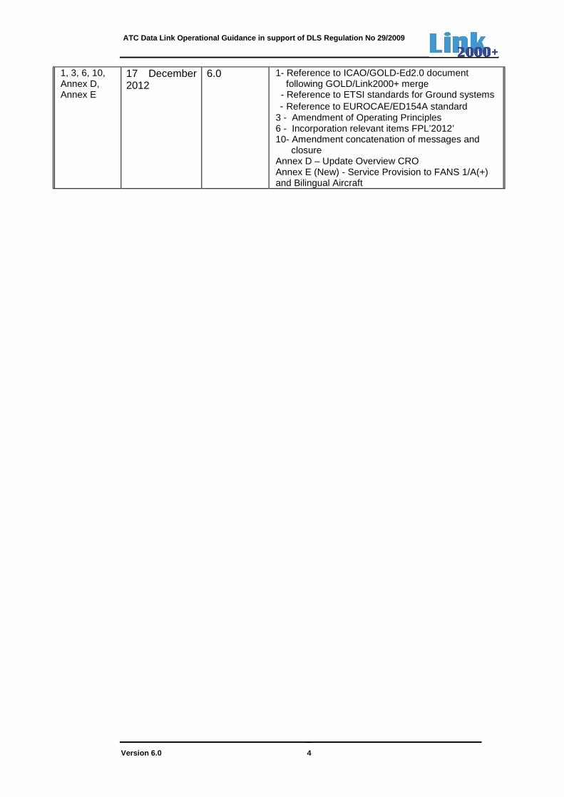
1, 3, 6, 10, Annex D, Annex E
17 December 2012
6.0 1- Reference to ICAO/GOLD-Ed2.0 document following GOLD/Link2000+ merge - Reference to ETSI standards for Ground systems - Reference to EUROCAE/ED154A standard 3 - Amendment of Operating Principles 6 - Incorporation relevant items FPL’2012’ 10- Amendment concatenation of messages and closure
Annex D – Update Overview CRO Annex E (New) - Service Provision to FANS 1/A(+) and Bilingual Aircraft

ATC Data Link Operational Guidance in support of DLS Regulation No 29/2009
Version 6.0 5
TABLE OF CONTENTS
1. INTRODUCTION..........................................................................................................................10
1.1 Overview ..............................................................................................................................10
1.2 Data link applications ...........................................................................................................10
1.3 Background ..........................................................................................................................10
1.4 Scope ...................................................................................................................................12
1.5 Document description ..........................................................................................................12
1.5.1 Meaning of phrases ......................................................................................................12
1.5.2 Document organisation.................................................................................................14
1.5.3 Acronyms ......................................................................................................................15
1.5.4 Glossary of terms..........................................................................................................17
1.6 References...........................................................................................................................20
2. AIRSPACE ...................................................................................................................................22
3. OPERATING PRINCIPLES..........................................................................................................23
4. CPDLC APPLICATION ................................................................................................................24
4.1 CPDLC messages................................................................................................................24
4.2 CPDLC message attributes .................................................................................................24
5. DESCRIPTION OF SERVICES ...................................................................................................25
5.1 General ................................................................................................................................25
5.2 DLIC - Data Link Initiation Capability ...................................................................................25
5.2.1 Logon function ..............................................................................................................25
5.2.1.1 Operating method .................................................................................................25
5.2.1.2 Diagram.................................................................................................................26
5.2.2 Contact function ............................................................................................................27
5.2.2.1 Operating method .................................................................................................27
5.2.2.2 Diagram.................................................................................................................27
5.3 ACM – ATC Communications Management ........................................................................28
5.3.1 ACM service description ...............................................................................................28
5.3.2 Examples of ACM operating methods using ‘CONTACT’ instruction...........................28
5.3.2.1 Transfer from a T-ATSU to a R-ATSU, both using CPDLC and using LOF and NAN .............................................................................................................29
5.3.2.2 Transfer from a T-ATSU to a R-ATSU, both using CPDLC and using DLIC Contact function..................................................................................................31
5.3.2.3 Transfer from a T-ATSU not using CPDLC to a R-ATSU using CPDLC ..............33
5.3.2.4 Transfer from a T-ATSU using CPDLC to a R-ATSU not using CPDLC ..............35
5.3.2.4.3 Examples.....................................................................................................36
5.3.2.5 Transfer and/or change of frequency, using CPDLC, with no change of CPDLC connection – CPDLC in use by all sectors ............................................38
ATC Data Link Operational Guidance in support of DLS Regulation No 29/2009
Version 6.0 6
5.3.2.6 Transfer and/or change of frequency, using CPDLC, with no change of CPDLC connection - CPDLC not in use by a sector ..........................................39
5.3.3 ACM service using 'MONITOR' instruction ...................................................................41
5.3.4 Transfer of data communications with open dialogues ................................................41
5.3.4.1 Open ground-initiated dialogues ...........................................................................41
5.3.4.2 Open air-initiated dialogues ..................................................................................42
5.3.5 ACM messages.............................................................................................................42
5.4 ACL – ATC Clearances........................................................................................................42
5.4.1 ACL service description ................................................................................................42
5.4.2 ACL operating methods ................................................................................................43
5.4.2.1 Flight crew request with controller clearance response........................................43
5.4.2.2 Flight crew request with controller UNABLE response .........................................44
5.4.2.3 Flight crew request with controller STANDBY response ......................................45
5.4.2.4 Controller clearance with flight crew WILCO response ........................................46
5.4.2.5 Controller clearance with flight crew UNABLE response......................................47
5.4.2.6 Controller clearance with flight crew STANDBY response ...................................48
5.4.3 ACL messages..............................................................................................................49
5.5 AMC - ATC Microphone Check............................................................................................49
5.5.1 AMC service description ...............................................................................................49
5.5.1.1 AMC operating method .........................................................................................49
5.5.1.2 Diagram.................................................................................................................50
5.5.1.3 AMC message.......................................................................................................50
5.6 Timers ..................................................................................................................................50
5.6.1 Technical response (LACK) timer.................................................................................51
5.6.2 Latency time monitor ....................................................................................................51
5.6.3 Expiration timers ...........................................................................................................52
5.6.3.1 Controller initiated dialogues.................................................................................52
5.6.3.2 Flight crew-initiated dialogues...............................................................................54
6. CPDLC PROCEDURES...............................................................................................................55
7. GROUND SYSTEMS SUPPORT.................................................................................................66
7.1 Display of the CPDLC operational status ............................................................................66
7.2 Ground systems support for the exchange of CPDLC messages .......................................66
7.3 System support for the transfer of CPDLC with open dialogues .........................................67
7.4 Ground system support for the commanded termination of CPDLC ...................................67
7.4.1 Flight crew commanded CPDLC termination ...............................................................67
7.4.2 Controller commanded CPDLC termination .................................................................67
7.5 Ground system support for CPDLC disabling/enabling .......................................................68
7.6 Ground system support in the event of CPDLC failure........................................................68
7.7 Ground systems support for ground-ground forwarding of DLIC Information .....................68
7.7.1 Overview .......................................................................................................................68

ATC Data Link Operational Guidance in support of DLS Regulation No 29/2009
Version 6.0 7
7.7.2 Abnormal events ...........................................................................................................69
7.8 Recording.............................................................................................................................71
8. HUMAN FACTORS GUIDELINES FOR CPDLC .........................................................................72
8.1 Consideration of Human Factors .........................................................................................72
8.2 Human Factors benefits associated with the use of CPDLC...............................................72
8.2.1 Reduction of voice channel congestion ........................................................................72
8.2.2 Decrease in communication errors ...............................................................................73
8.2.3 Reduction in ATC communication workload.................................................................73
8.2.4 Increased flexibility in handling ATC communication tasks..........................................73
8.2.5 Possibility of a flexible task allocation within the controller team .................................73
8.3 Human Factors issues associated with the use of CPDLC .................................................74
8.3.1 Communication delays in CPDLC ................................................................................74
8.3.2 Detection and processing of visual information ............................................................74
8.3.3 Competition for visual resources ..................................................................................75
8.3.4 Composition of CPDLC messages ...............................................................................75
8.3.5 Controller team situation awareness ............................................................................75
8.3.6 Possibility of flexible task allocation in the controller team...........................................76
8.3.7 Sequential vs. parallel dialogues ..................................................................................77
8.3.8 Rigidity of data link communication ..............................................................................77
8.3.9 Choice between voice and data link for a dialogue ......................................................77
8.3.10 Reversion to voice communication.........................................................................78
8.3.11 Mix of aircraft with and without CPDLC capability..................................................78
8.3.12 Availability of CPDLC..............................................................................................79
9. TRAINING GUIDELINES FOR THE USE OF CPDLC.................................................................80
9.1 Data link services and CPDLC messages ...........................................................................80
9.2 Use of CPDLC......................................................................................................................80
9.3 Timers and system errors ....................................................................................................81
9.4 Abnormal events ..................................................................................................................81
9.5 Human machine interface ....................................................................................................82
10. GUIDELINES FOR CONCATENATED MESSAGES AND CLOSURE .......................................83
10.1 Introduction ..........................................................................................................................83
10.2 CPDLC message attributes .................................................................................................83
10.3 Controller-initiated concatenation of message elements .....................................................83
10.3.1 Operational guidance for the use of concatenated CPDLC messages..................83
10.3.2 Concatenation of message elements with response attribute other than Y ...........84
10.3.3 Concatenation of message elements with W/U, A/N, R or Y response attribute with message elements with Y response attribute. ................................................86
10.4 Flight crew-initiated concatenation of message elements ...................................................86
10.4.1 Operational guidance for the use of concatenated messages ...............................86
ATC Data Link Operational Guidance in support of DLS Regulation No 29/2009
Version 6.0 8
10.5 Flight crew responses to controller-initiated concatenated messages ................................86
10.5.1 Responding to concatenation of message elements with response attribute other than Y ............................................................................................................87
10.6 Guidance for ground- and aircraft systems supporting concatenation of message elements W/U with Y response attributes..........................................................................87
10.6.1 Recommended concatenation of uplink message elements ..................................87
10.6.2 Responding to uplink concatenated messages......................................................88
11. NOTIFICATION OF DATA LINK SERVICES...............................................................................90
ANNEX A: EUROCONTROL SPECIFICATION - CPDLC MESSAGE SET FOR GROUND SYSTEMS ..........................................................................................................................92
ANNEX B: TIME SEQUENCE DIAGRAMS GROUND-GROUND FORWARDING OF LOGON DATA..................................................................................................................................98
ANNEX C: URGENCY, ALERT AND RESPONSE ATTRIBUTES.......................................................101
ANNEX D: OVERVIEW CRO SYSTEM PERFORMANCE AND PROBLEM REPORTING ..............103
ANNEX E: SERVICE PROVISION TO FANS 1/A(+) AND BILINGUAL AIRCRAFT ..........................104
LIST OF TABLES Table 1-1: Acronyms 16
Table 1-2: Glossary of terms 19
Table 5-1: DLIC - Operating Method for Logon function 26
Table 5-2: DLIC - Operating Method for Contact Function 27
Table 5-3: ACM - Operating method “Transfer between a T-ATSU and R-ATSU both using CPDLC and using LOF and NAN” 30
Table 5-4: ACM - Operating method “Transfer between a T-ATSU and R-ATSU both using CPDLC and using Contact function” 32
Table 5-5: ACM - Operating method “Transfer between a T-ATSU not using CPDLC and R-ATSU using CPDLC” 34
Table 5-6: ACM - Operating method “Transfer between a T-ATSU using CPDLC and R-ATSU not using CPDLC” 35
Table 5-7: ACM - Operating method “Transfer within an ATSU, using CPDLC, with no change of CPDLC connection” 39
Table 5-8: ACM - Operating method “Transfer within an ATSU with 41
Table 5-9: ACL - Operating method “Flight crew initiated request and controller clearance response” 43
Table 5-10: ACL - Operating method ”Flight crew initiated request and controller UNABLE response” 44
Table 5-11: ACL - Operating method “Flight crew initiated request and controller STANDBY response” 45
Table 5-12: ACL - Operating method “Controller clearance with flight crew WILCO response” 46
Table 5-13: ACL - Operating method “Controller clearance with flight crew UNABLE response” 47
Table 5-14: ACL - Operating method “Controller clearance with flight crew STANDBY response” 48
Table 5-15: AMC Operating method 50
ATC Data Link Operational Guidance in support of DLS Regulation No 29/2009
Version 6.0 9
LIST OF FIGURES
Figure 2-1: Geographical scope of the area of applicability and key dates 22
Figure 5-1: DLIC - Diagram for Logon Function 26
Figure 5-2: DLIC - Diagram for Contact Function 28
Figure 5-3: ACM - Diagram “Transfer from a T-ATSU to an R-ATSU, both using CPDLC and using LOF and NAN” 31
Figure 5-4: ACM - Diagram “Transfer from a T-ATSU to an R-ATSU, both using CPDLC and using Contact function” 33
Figure 5-5: ACM - Diagram ”Transfer from a T-ATSU not using CPDLC to an R- ATSU using CPDLC” 34
Figure 5-6: ACM - Diagram ”Transfer from a T-ATSU using CPDLC to an R- ATSU not using CPDLC” 36
Figure 5-7: Scenarios Inter-ATSU transfers including an ATSU, not using CPDLC 38
Figure 5-8: ACM - Diagram “Transfer and/or change of frequency, 39
Figure 5-9: Scenario intra-ATSU transfer with a sector, not using CPDLC 40
Figure 5-10: ACL - Diagram “Flight crew request with a controller clearance” 44
Figure 5-11: ACL - Diagram “Flight crew request with a controller UNABLE response” 45
Figure 5-12: ACL - Diagram “Flight crew request with a controller STANDBY response” 46
Figure 5-13: ACL - Diagram “Controller clearance with a WILCO flight crew response” 47
Figure 5-14: ACL - Diagram “Controller clearance with an UNABLE flight crew response” 48
Figure 5-15: ACL – Diagram ”Controller Clearance with STANDBY” 49
Figure 5-16: AMC Diagram 50
Figure 5-17: Timers used in a controller-initiated dialogue 53
Figure 5-18: Timers used in a flight crew-initiated dialogue 54
Figure 7-1: Ground-ground Forwarding 69
Figure 7-2: Abrogated R-ATSU 71
ATC Data Link Operational Guidance in support of DLS Regulation No 29/2009
Version 6.0 10
1. INTRODUCTION
1.1 Overview
The implementation of data link is one of the key operational improvements that will alleviate voice channel congestion. Data link implementation will provide benefits to ATC efficiency, capacity and communications in order to accommodate the expected growth in air traffic demand.
1.2 Data link applications
A data link application facilitates specific Air Traffic Management (ATM) operational functionalities, using a specific data link technology. Examples of these applications are listed below.
• Context Management (CM);
• Controller Pilot Data Link Communications (CPDLC);
• Data Link Flight Information Service (DFIS);
• Automatic Dependent Surveillance – Addressed (ADS-C);
• Automatic Dependent Surveillance - Broadcast (ADS-B).
The LINK2000+ Programme objective is to coordinate the implementation of the CM and CPDLC applications and the derived data link services across States to which EC Regulation No 29/2009 [1] applies.
1.3 Background
In 1999 an industry-level business case and investment analysis was conducted by the CNS/ATM Focus Team (C/AFT). The overall analysis was led by American Airlines and the European analysis was led by KLM and reviewed by EUROCONTROL. Together with a relevant cost benefit analysis, developed by EUROCONTROL, results showed that the phased implementation of ATS Data Link Applications would be beneficial for airspace users in Europe.
At their sixth meeting in 2000, the Transport Ministers of the ECAC Member States endorsed the EUROCONTROL ATM Strategy for the years 2000+. The strategy had been aligned with the approved ECAC ATM Institutional Strategy, the EUROCONTROL Revised Convention and the relevant ICAO CNS/ATM global plans.
In the context of this strategy, the EUROCONTROL LINK 2000+ Programme was launched. The EUROCONTROL ATM/CNS Consultancy Group (ACG), at its 9th Meeting in September 2000, endorsed a Master Plan for the LINK 2000+ Programme and supported its creation. The Programme has received subsequent endorsement from the Chief Executive Officers of the European Air Navigation Service Providers (ANSPs). In the framework of the Single European Sky Initiative, the use of data link services as defined by the LINK2000+ Programme has been regulated by the European Commission (EC). The EC Regulation No 29/2009 [1] has been
ATC Data Link Operational Guidance in support of DLS Regulation No 29/2009
Version 6.0 11
published in the Official Journal of the EC on 16h January 2009 together with the EC Regulation No 30/2009 [2] for Flight Data Processing Systems for the exchange flight plan data, using Logon Forwarding (LOF) and Next Authority Notified (NAN) in support of data link services. These two Regulations apply to the entire European upper airspace above FL285 (Refer to section 2 for more details). This does not mean that CPDLC operations are limited above FL285, rather it aims to govern data link equipage.
Note: Several ANSPs have indicated to use CPDLC in their upper airspace below FL285. At its meeting in November 2010, the European Air Navigation Planning Group (EANPG) of ICAO supported the need for a review of the Global Operational Data Link Document (GOLD)-Ed1.0 and LINK2000+ Operational Guidance documents with the aim to develop an operational data link guidance (GOLD Ed 2.0 [15]) that could be used in the entire ICAO EUR Region for all data link implementations and which would be globally harmonized with guidance used in the oceanic/remote regions. This would ensure global harmonization of the current data link implementations and provide a path to the convergence of the future data link communications systems. A LINK2000+ Task Force participated in the GOLD-ad-hoc Working group to:
a) review the LINK2000+ guidance against GOLD and to amend GOLD , and b) merge LINK2000+ Operational Guidance and GOLD as basis for a Global
Operational Guidance (GOLD Ed 2.0). The LINK2000+ ATC Data Link Operational Guidance material should be used in conjunction with GOLD-Ed 2.0 [15]. Note 1: While the GOLD document functions as a globally operational document for DLIC, CPDLC and ADS-C operations, the LINK2000+ ATC Data Link Operational Guidance is specifically developed for the use of DLIC and CPDLC in support of EC Regulation No 29/2009. Note 2: At the time of writing of the LINK2000+ ATC Data Link Operational Guidance-version 6.0, the GOLD-Ed 2.0 has not been published. Publication is foreseen for 1Q2013.
ATC Data Link Operational Guidance in support of DLS Regulation No 29/2009
Version 6.0 12
1.4 Scope
The scope of this document covers the implementation and the use of a number of data link services, derived from the CM and CPDLC applications and regulated by EC Regulation No 29/2009 [1 ]. In parallel to the Data Link Regulation, the EUROCONTROL Specification [4] has been developed as a Means of Compliance to the Data Link Regulation. The document is targeted at a readership comprising operational staff and controller training staff.
The main objective of the document is to provide operationally oriented guidelines to use CPDLC in a harmonised way. If required, appropriate local authorities may promulgate further specific conditions for its use.
The EUROCONTROL Specification comprises the following data link services, used during en-route operations in upper airspace:
• DLIC - Data Link Initiation Capability (Logon and Contact)
• ACM - ATC Communications Management
• ACL - ATC Clearances
• AMC - ATC Microphone Check
The document contains a collection of the relevant ICAO provisions and sets out general principles and rules to be followed when implementing these services.
It is intended that this document will assist ANSPs implementing DLIC, ACM, ACL and AMC services by addressing necessary steps to be followed in creating the legal and operational environment. The document is intended to be amended as experience is gained during the use of CPDLC.
The main topics addressed are as follows:
• How the services are to be used;
• Generic ATC procedures;
• Generic human factors guidelines;
• Generic training guidelines;
• ATS system support.
1.5 Document description
1.5.1 Meaning of phrases
This document uses the following specific phrases as follows:
1. “Shall”: ICAO: Any specification for physical characteristics, configuration, matériel, performance, personnel or procedure, the uniform application of which is recognized as necessary for the safety or regularity of international air navigation and to which Contracting States will conform in accordance with the Convention; in the event of impossibility of compliance, notification to the Council is compulsory under Article 38.
ATC Data Link Operational Guidance in support of DLS Regulation No 29/2009
Version 6.0 13
EUROCAE ED-120 and ED-110B Indicates a mandated criterion; i.e. compliance with the criterion is mandatory and no alternative may be applied;
2. “Should”: ICAO: Any specification for physical characteristics, configuration, matériel, performance, personnel or procedure, the uniform application of which is recognized as desirable in the interest of safety, regularity or efficiency of international air navigation, and to which Contracting States will endeavour to conform in accordance with the Convention
EUROCAE ED-120 and ED-110B Indicate that, although the criterion is regarded as the preferred option, alternative criteria may be applied. In such cases, alternatives should be identified in appropriate approval plans and agreement sought from the approval authority;
3. “May” means a procedure, or instruction is permissive, optional or alternative;
4. “Will” is only used for informative or descriptive writing, e.g. ”transfer of CPDLC will coincide ….” is not an instruction to the controller;
5. “Instruct” indicates that an ATM operator is required to issue binding positive commands to the addressee;
6. “Advise” means that an ATM operator is required to suggest a non-binding behaviour to the addressee;
7. Throughout this guidance document, whenever a noun is used referring to a person providing ATM services (e.g. controller or flight crew), that word is to be understood as covering both sexes. For user-friendliness purposes, the pronoun “he” is used in all cases and shall in no case imply any form of sexual discrimination.

ATC Data Link Operational Guidance in support of DLS Regulation No 29/2009
Version 6.0 14
1.5.2 Document organisation
Section 1 provides an introduction to this guidance document. It gives some background information, the scope of the EUROCONTROL Specification [4] and organisation of the document.
Section 2 gives a description of the airspace of applicability, the geographical scope of the data link service provision and key dates prescribed by the two EC Regulations on data link services.
Section 3 provides the four operating principles that are applicable to the use of DLIC, ACL, ACM and AMC services.
Section 4 gives an overview of the urgency, alert and response attributes of CPDLC messages and should be read together with Annex C.
Section 5 describes the data link services DLIC, ACL, ACM and AMC, including timers used in aircraft and ground systems.
Section 6 provides requirements and recommendations for the data link related ATC procedures, which have been extracted from the relevant ICAO and EUROCAE documents.
Section 7 gives requirements and recommendations for ATS systems to support the use of CPDLC and ground-ground forwarding of DLIC information.
Section 8 provides an analysis of Human Factors benefits and issues related to the use of CPDLC. On the basis of this analysis, recommendations for training and procedures are formulated.
Section 9 provides training guidelines for controller pilot data link communications to assist in the development of a training program for CPDLC for controllers.
Section 10 provides guidance for uplink and downlink concatenated messages and closure within the envisaged environment.
Section 11 summarises the notifications required of data link services to airspace users.
Annex A provides the CPDLC message set for ground implementations in accordance with the EUROCONTROL Specification [4].
Annex B provides time sequence diagrams for ground-ground forwarding of DLIC information.
Annex C describes the urgency, alert and response CPDLC message attributes in more detail and provides their precedence.
Annex D provides an overview of the Central Reporting Office for System Performance and Problem Reporting.
Annex E considers the Service Provision to FANS 1/A(+) and Bilingual Aircraft in the Continental European Region.
Appendix A presents a list of contributors to this document.
ATC Data Link Operational Guidance in support of DLS Regulation No 29/2009
Version 6.0 15
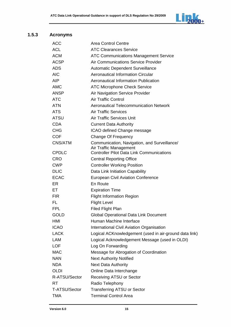
1.5.3 Acronyms
ACC Area Control Centre
ACL ATC Clearances Service
ACM ATC Communications Management Service
ACSP Air Communications Service Provider
ADS Automatic Dependent Surveillance
AIC Aeronautical Information Circular
AIP Aeronautical Information Publication
AMC ATC Microphone Check Service
ANSP Air Navigation Service Provider
ATC Air Traffic Control
ATN Aeronautical Telecommunication Network
ATS Air Traffic Services
ATSU Air Traffic Services Unit
CDA Current Data Authority
CHG ICAO defined Change message
COF Change Of Frequency
CNS/ATM Communication, Navigation, and Surveillance/ Air Traffic Management
CPDLC Controller Pilot Data Link Communications
CRO Central Reporting Office
CWP Controller Working Position
DLIC Data Link Initiation Capability
ECAC European Civil Aviation Conference
ER En Route
ET Expiration Time
FIR Flight Information Region
FL Flight Level
FPL Filed Flight Plan
GOLD Global Operational Data Link Document
HMI Human Machine Interface
ICAO International Civil Aviation Organisation
LACK Logical ACKnowledgement (used in air-ground data link)
LAM Logical Acknowledgement Message (used in OLDI)
LOF Log On Forwarding
MAC Message for Abrogation of Coordination
NAN Next Authority Notified
NDA Next Data Authority
OLDI Online Data Interchange
R-ATSU/Sector Receiving ATSU or Sector
RT Radio Telephony
T-ATSU/Sector Transferring ATSU or Sector
TMA Terminal Control Area

ATC Data Link Operational Guidance in support of DLS Regulation No 29/2009
Version 6.0 16
UAC Upper Airspace Control
UIR Upper Information Region Table 1-1: Acronyms
ATC Data Link Operational Guidance in support of DLS Regulation No 29/2009
Version 6.0 17
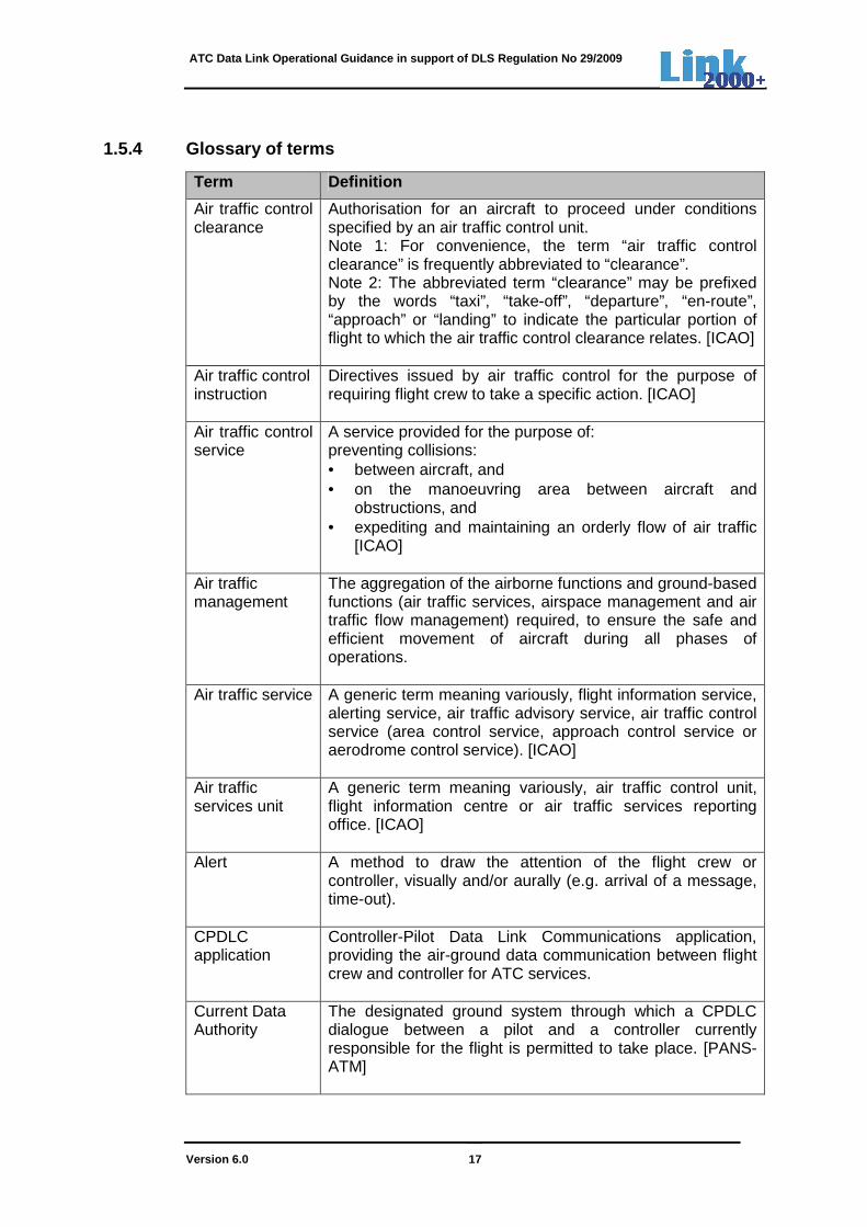
1.5.4 Glossary of terms
Term Definition
Air traffic control clearance
Authorisation for an aircraft to proceed under conditions specified by an air traffic control unit. Note 1: For convenience, the term “air traffic control clearance” is frequently abbreviated to “clearance”. Note 2: The abbreviated term “clearance” may be prefixed by the words “taxi”, “take-off”, “departure”, “en-route”, “approach” or “landing” to indicate the particular portion of flight to which the air traffic control clearance relates. [ICAO]
Air traffic control instruction
Directives issued by air traffic control for the purpose of requiring flight crew to take a specific action. [ICAO]
Air traffic control service
A service provided for the purpose of: preventing collisions: • between aircraft, and • on the manoeuvring area between aircraft and
obstructions, and • expediting and maintaining an orderly flow of air traffic
[ICAO]
Air traffic management
The aggregation of the airborne functions and ground-based functions (air traffic services, airspace management and air traffic flow management) required, to ensure the safe and efficient movement of aircraft during all phases of operations.
Air traffic service A generic term meaning variously, flight information service, alerting service, air traffic advisory service, air traffic control service (area control service, approach control service or aerodrome control service). [ICAO]
Air traffic services unit
A generic term meaning variously, air traffic control unit, flight information centre or air traffic services reporting office. [ICAO]
Alert A method to draw the attention of the flight crew or controller, visually and/or aurally (e.g. arrival of a message, time-out).
CPDLC application
Controller-Pilot Data Link Communications application, providing the air-ground data communication between flight crew and controller for ATC services.
Current Data Authority
The designated ground system through which a CPDLC dialogue between a pilot and a controller currently responsible for the flight is permitted to take place. [PANS-ATM]

ATC Data Link Operational Guidance in support of DLS Regulation No 29/2009
Version 6.0 18
Term Definition
Data link application
A data link application is the implementation of data link technology to achieve specific air traffic management (ATM) operational functionalities (e.g. voice communications management)
Data link service A data link service is a set of ATM related dialogues, both system and manually supported within a data link application, which have a clearly defined operational goal. (In this context DLIC, ACL, ACM, and AMC)
Dialogue A two-way information exchange between the originating user and the receiving user, from opening of the dialogue to closure of the dialogue.
Expiration Timer-initiator (tts)
Timer used by a sending system to detect the absence of an operational response from the remote system in an acceptable period of time. The timer-sender starts when the message is released by the initiator (e.g. by pressing “ENTER”). It ends when an indication of the receipt of the operational reply is provided to the initiator.
Expiration Timer-responder (ttr)
Timer used by a receiving system to detect the absence of a response to a received message in an acceptable period of time. The timer-responder starts when an indication of the receipt of the message is provided to the responder. It ends when the operational reply is released by the responder (e.g. by pressing “ENTER”).
Flight information service
A service provided for the purpose of giving advice and information useful for the safe and efficient conduct of flights. [ICAO]
Flight plan Specified information provided to air traffic services units, relative to an intended flight or portion of a flight of an aircraft. [ICAO] A flight plan can take several forms, such as: Current flight plan (CPL). The flight plan, including changes, if any, brought about by subsequent clearances. Note: When the word “message” is used as a suffix to this term, it denotes the content and format of the current flight plan data sent from one unit to another. Filed flight plan (FPL). The flight plan as filed with an ATS unit by the flight crew or a designated representative, without any subsequent changes. Note: When the word “message” is used as a suffix to this term, it denotes the content and format of the filed flight plan data as transmitted.
ATC Data Link Operational Guidance in support of DLS Regulation No 29/2009
Version 6.0 19
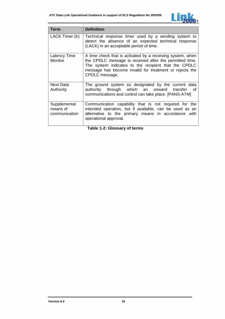
Term Definition
LACK Timer (tr) Technical response timer used by a sending system to detect the absence of an expected technical response (LACK) in an acceptable period of time.
Latency Time Monitor
A time check that is activated by a receiving system, when the CPDLC message is received after the permitted time. The system indicates to the recipient that the CPDLC message has become invalid for treatment or rejects the CPDLC message.
Next Data Authority
The ground system so designated by the current data authority through which an onward transfer of communications and control can take place. [PANS-ATM]
Supplemental means of communication
Communication capability that is not required for the intended operation, but if available, can be used as an alternative to the primary means in accordance with operational approval. Table 1-2: Glossary of terms
ATC Data Link Operational Guidance in support of DLS Regulation No 29/2009
Version 6.0 20
1.6 References
The following references were used as input to this document:
1. Commission Regulation (EC) No29/2009, 16 January 2009 - laying down requirements on data link services for the single European sky.
2. Commission Regulation (EC) No 30/2009, 16 January 2009 - amending Regulation (EC) No 1032/2006 as far as the requirements for automatic systems for the exchange of flight data supporting data link services are concerned.
3. ETSI Standard - EN 303-214 Ver 1.2.1 Data Link Services (DLS) System; Community Specification for application under the Single European Sky Interoperability Regulation EC 552/2004; Requirements for ground constituents and system testing. European Telecommunication Standards Institute (ETSI)
Note: ETSI EN 303-214 is intended to be equivalent to the provisions of the EUROCONTROL SPECIFICATION on Data Link Services relating to the ground system, with the addition of requirements on system testing.
4. EUROCONTROL Specification on Data Link Services, Edition 2.1, January 2009.
5. EUROCONTROL – Standard document for On-line Data Interchange (OLDI) DPS.ET1.ST06-STD-02-01, Edition 4.1, 16 January 2008.
6. EUROCAE Document ED-110B – Interoperability Requirements Standard for ATN Baseline 1, December 2007.
7. EUROCAE Document ED-111 - Functional Specifications for CNS/ATM Ground Recording, July 2002.
8. EUROCAE Document ED-120 - Safety and Performance Requirements Standard for Air Traffic Data-Link Services in Continental Airspace, May 2004 and Change 1, April 2007 and Change 2, Oct 2007.
9. EUROCAE Document ED-154A – Future Air Navigation System 1/A –Aeronautical Telecommunication Network Interoperability Standard (FANS 1/A-ATN B1 Interop Standard), March 2012.
10. ICAO Annex 10 - Aeronautical Telecommunications - Volume II (Communications Procedures including those with PANS status).
11. ICAO Doc 4444 - Procedures for Air Navigation Services - Air Traffic Management (PANS-ATM) – Ed15, 22 November 2007
12. ICAO Doc 9694 - Manual of Air Traffic Services Data Link Applications, First Edition – 1999
13. ICAO Doc 7030/5 – Regional Supplementary Procedures – EUR Region, including Amendments for CPDLC
14. ICAO Human Factors Guidelines for Air Traffic Management (ATM) Systems, First Edition, Doc 9758-AN/966, 2000
15. ICAO Global Operational Data Link Document (GOLD) – Ed 2.0, ….2013

ATC Data Link Operational Guidance in support of DLS Regulation No 29/2009
Version 6.0 21
16. Goteman, Ö. - Flight crew and air traffic controller cooperation during Controller-Pilot Data Link Communication trials. SAS Technical Report. Ref.nr. GOT-050426, 2007.
17. Helleberg, J.R. & Wickens, C.D. - Effects of data-link modality and display redundancy on pilot performance: An attentional perspective. The International Journal of Aviation Psychology, 13(3), 189 – 210, 2003.
18. Navarro, C. & Sikorski, S. – Data link communication in flight deck operations: A synthesis of recent studies. The International Journal of Aviation Psychology, 9(4), 361 – 376, 1999.
ATC Data Link Operational Guidance in support of DLS Regulation No 29/2009
Version 6.0 22
2. AIRSPACE
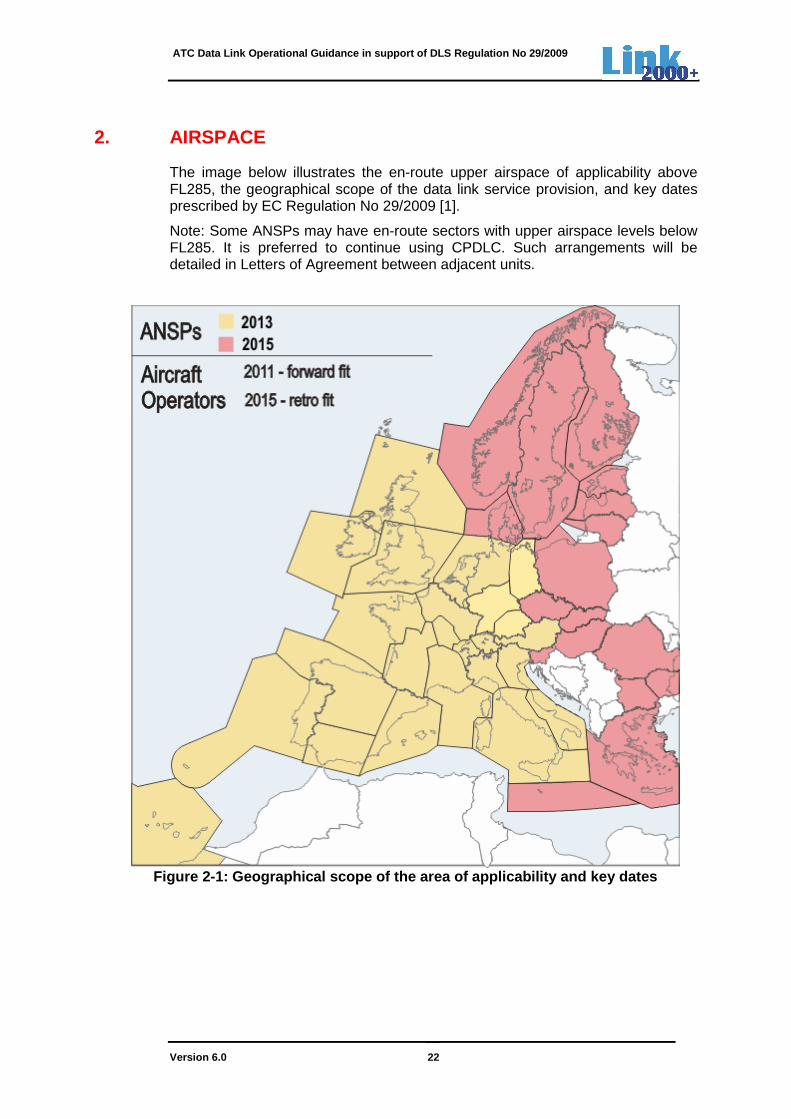
The image below illustrates the en-route upper airspace of applicability above FL285, the geographical scope of the data link service provision, and key dates prescribed by EC Regulation No 29/2009 [1].
Note: Some ANSPs may have en-route sectors with upper airspace levels below FL285. It is preferred to continue using CPDLC. Such arrangements will be detailed in Letters of Agreement between adjacent units.
Figure 2-1: Geographical scope of the area of appli cability and key dates

ATC Data Link Operational Guidance in support of DLS Regulation No 29/2009
Version 6.0 23
3. OPERATING PRINCIPLES
The following underlying principles apply to the use of CPDLC in the en-route upper airspace:
Principle A In support of the EC Regulation No 29/2009, CPDLC provisions shall respect the following limitations in the Continental European airspace:
The CPDLC implementation is limited to the provision of a supplementary means of communication. Voice shall remain the primary means of communication. CPDLC shall be only used for routine CPDLC exchanges during en-route operations in upper airspace and not for time-critical situations.
Note: Time-critical situation is a situation when a prompt controlling action is required in the provision of air traffic services. (Refer to GOLD [15] for more details)
Principle B The decision to use either voice or CPDLC shall be at the discretion of the controller and/or pilot involved.
Principle C
The provisions regarding the use of CPDLC shall respect the following Standard as contained in ICAO Annex 11, Chapter 3, para 3.5.1: “A controlled flight shall be under the control of only one air traffic control unit at any given time”.

ATC Data Link Operational Guidance in support of DLS Regulation No 29/2009
Version 6.0 24
4. CPDLC APPLICATION
4.1 CPDLC messages
The EUROCONTROL Specification contains a subset of the ICAO CPDLC message set to be used in ACL, ACM and AMC (See Annex A: list of CPDLC message elements).
As detailed in Annex A, some message elements are mandatory, while others are optional. An ATS authority may decide which optional message elements suits best to their needs. Subject to concatenation guidelines, described in section 10, some of these message elements may be concatenated and sent as a multi-element message.
4.2 CPDLC message attributes
Each CPDLC message element has Response, Urgency and Alert attributes.
Most CPDLC messages have the Response attribute, meaning that they require a valid response (e.g. CLIMB TO flight level 350 – Allowed response is either WILCO, UNABLE or STANDBY).
Given the type of messages to be implemented as part of the EUROCONTROL Specification, ground systems are required to use and adhere to the ‘Response’ attribute.
The use of Alert and Urgency (prioritisation of CPDLC messages) attributes is a local implementation option.
A full list of ‘Response’, ‘Urgency’ and ‘Alert’ attributes is presented in Annex C.
ATC Data Link Operational Guidance in support of DLS Regulation No 29/2009
Version 6.0 25
5. DESCRIPTION OF SERVICES
5.1 General
Diagrams are presented for each of the data link services. They are used to describe the operating method for the data link service. The conventions used are as follows:
• Human initiated air-ground messages are in blue line;
• System generated air-ground messages are in red line;
• Ground-ground messages are in black line;
• Messages that are optional are in dotted line;
• Messages passed by voice are marked in red text;
• LACK messages are not presented in the diagrams.
5.2 DLIC - Data Link Initiation Capability
DLIC is a data link service that is derived from the Context Management application to provide the necessary information to allow data link communications between an ATSU and aircraft.
The DLIC service makes it possible to:
• Unambiguously associate flight data from the aircraft with flight plan data stored by an ATSU.
• Exchange the supported application type and version information and to deliver application address information.
The DLIC service is executed prior to the first use of the CPDLC application.
The DLIC service consists of the Logon and Contact functions.
5.2.1 Logon function
The logon function is a means of exchanging application information between an aircraft and a specific ATSU. It also provides flight data to that ATSU.
5.2.1.1 Operating method
The DLIC Logon function operating method is as follows:
ATC Data Link Operational Guidance in support of DLS Regulation No 29/2009
Version 6.0 26
Step Operating Method
1 The flight crew initiates a logon request to the ATSU
Note1: Flight crew should initiate a logon request, between 10 and 30 minutes before entering the airspace of an UIR. For aircraft departing from airports beneath, or in close proximity to, the ATSU’s airspace, the logon can be initiated on the ground. Specific local requirements about the timing of logon initiation may be found in the AIC/AIP.
Note 2: When flight crew has made an initial logon to the first en-route ATSU, while not yet under the control of this ATSU, and hereafter this ATSU has abrogated the service provision, the flight crew should initiate a new logon request to the new adjacent en-route ATSU.
(The abrogated ATSU may not be aware about the new adjacent ATSU. For more details on ATSU abrogation, see 7.7.2).
2 The ATSU system attempts to associate the flight data received from the aircraft with the corresponding flight plan
3 ATSU system sends a logon response to the aircraft.
Note: The controller and flight crew may get an indication of the logon status on the HMI
Table 5-1: DLIC - Operating Method for Logon functi on
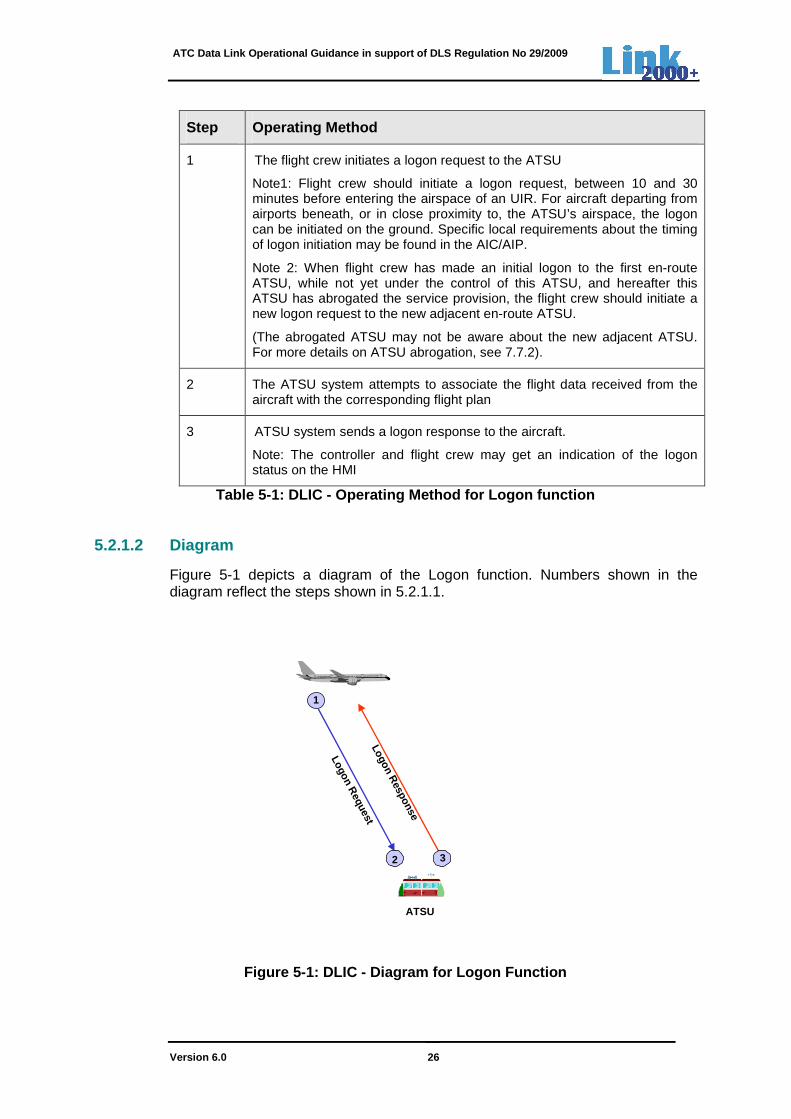
5.2.1.2 Diagram
Figure 5-1 depicts a diagram of the Logon function. Numbers shown in the diagram reflect the steps shown in 5.2.1.1.
Figure 5-1: DLIC - Diagram for Logon Function
1
Logon Request
Logon Response
2 3
ATSU

ATC Data Link Operational Guidance in support of DLS Regulation No 29/2009
Version 6.0 27
5.2.2 Contact function
The contact function provides a method for an ATSU system to request the aircraft system to initiate the logon function with another ATSU, indicated in the contact request.
Note: In accordance with the Regulation for Flight Data Processing Systems concerning the exchange of flight plan data, Logon Forwarding (LOF) and Next Authority Notified (NAN), should be used to forward the flight information to the next ATSU. If the ground-ground forwarding fails, the contact function will be used. Ground-ground forwarding is further explained in 7.7.
5.2.2.1 Operating method
The DLIC contact function operating method is as follows:
Step Operating Method
1 The requesting ATSU system sends a contact request to the aircraft, specifying the ATSU ICAO facility designation and CM-application address with which the aircraft is to initiate data link
2 The aircraft system automatically sends a logon request to the specified ATSU system
3 The ATSU system attempts to associate the flight data received from the aircraft with the appropriate flight plan
4 ATSU system sends a logon response to the aircraft system. Note: The controller may get an indication of the logon status on the CWP
5 The aircraft system sends a contact response to the requesting ATSU system
Note: The flight crew may get an indication of the logon status on the HMI
Table 5-2: DLIC - Operating Method for Contact Fun ction
5.2.2.2 Diagram

ATC Data Link Operational Guidance in support of DLS Regulation No 29/2009
Version 6.0 28
Figure 5-2 depicts a diagram of the ‘contact’ function. Numbers shown in the diagram reflect the steps shown in 5.2.2.1.
Figure 5-2: DLIC - Diagram for Contact Function
5.3 ACM – ATC Communications Management
5.3.1 ACM service description
The ACM service provides automated assistance to flight crews and controllers for conducting the transfer of ATC communications (voice and CPDLC), respecting the operational rule that there is only one ATC controlling authority.
ACM enables the:
• Initial establishment of CPDLC with an ATSU;
• Transfer of CPDLC and voice for a flight from one ATSU to the next ATSU, or the instruction to change voice channels within an ATSU or sector;
• Termination of CPDLC with an ATSU.
The transfer of CPDLC will coincide with the transfer of voice communications.
5.3.2 Examples of ACM operating methods using ‘CONT ACT’ instruction
This document only considers the following main four scenarios:
1. Transfer from a T-ATSU to a R-ATSU both using CPDLC;
2. Transfers from a T-ATSU not using CPDLC to a R-ATSU using CPDLC;
Con
tact
Req
uest
1
2
Logon Response
3 4
Con
tact
Res
pons
e
Logon Request
5
RequestingATSU
SpecifiedATSU

ATC Data Link Operational Guidance in support of DLS Regulation No 29/2009
Version 6.0 29
3. Transfers from a T-ATSU, using CPDLC to a R-ATSU, not using CPDLC;
4. Transfer and/or change of frequency, using CPDLC, with no change of CPDLC connection.
Note 1: For the complete set of scenarios, see ED-120 [8] and ED110B [6].
Note 2: The ‘MONITOR [unit name] [frequency]’ (UM120) message is currently not used operationally and is therefore not part of the operating method. See also 5.3.3.
Non-contiguity of airspace regarding non-use of CPDLC for transfers between ATSUs (scenarios 2 and 3) or between sectors within a present ATSU (scenario 4) may occur temporarily during the transition period towards Europe-wide implementation in 2015 or permanently for ATSUs or sectors within an ATSU who’s airspace are below FL285 and as such do not provide CPDLC services below FL285. This is illustrated through a number of sample scenarios.
Note: FL285 or above is the level for which an ATSU is required to provide CPDLC services.
5.3.2.1 Transfer from a T-ATSU to a R-ATSU, both us ing CPDLC and using LOF and NAN
5.3.2.1.1 Operating method
The ACM service operating method used for transfers between a T-ATSU and R-ATSU both using CPDLC and the use of OLDI messages Logon Forwarding (LOF) and Next Authority Notified (NAN), is as follows:
Step Operating Method
1 The T-ATSU system sends an OLDI-LOF message to the R-ATSU, containing the aircraft logon parameters
Note 1: The LOF is transmitted at a prescribed time or distance (determined bilaterally) before the transfer of CPDLC to the R-ATSU
Note 2: The R-ATSU system attempts to associate the LOF information with the corresponding flight plan
2 The T-ATSU system automatically sends an NDA notification to the aircraft system, authorising the aircraft to accept a CPDLC connection request from the R-ATSU
Note 1: The NDA notification is transmitted by the T-ATSU at a prescribed time or distance (determined bilaterally) before the transfer of CPDLC to the R-ATSU
Note 2: The T-ATSU is prohibited from sending the NDA notification until the T-ATSU is the current data authority (CDA)
3 The T-ATSU system sends an OLDI-NAN message to the R-ATSU triggering the CPDLC-start request.
4 The R-ATSU system sends a ‘CPDLC-start’ request to the aircraft system
Note: If the NAN message has not been received, the R-ATSU triggers

ATC Data Link Operational Guidance in support of DLS Regulation No 29/2009
Version 6.0 30
Step Operating Method
a CPDLC-start request upon crossing the Coordination-point at time parameter/distance before first sector or aircraft calling the first sector
5 The aircraft system confirms the connection establishment via a ‘CPDLC-start’ response
6 The T-ATSU controller sends the data link ‘Contact’ message, instructing the flight crew to transfer voice communications to the specified voice channel of the R-ATSU. This is sent with a ‘CPDLC-end’ request.
Note: Ground systems prohibit the transmission of any other CPDLC messages once the T-ATSU initiates the Contact instruction.
7 The aircraft receives the ‘Contact’ message. The flight crew sends a WILCO response with a ‘CPDLC-end’ response
Note: The WILCO response terminates the CPDLC connection with the T- ATSU
8 Upon sending the WILCO response, the flight crew tunes to the new voice channel and contacts the R-ATSU controller by voice
9 After termination of CPDLC with the T-ATSU, the aircraft system notifies the R-ATSU that it is the current data authority (CDA)
Note: The aircraft system indicates to the flight crew that the R-ATSU is CDA
10 The R-ATSU system notifies the controller when CPDLC has been enabled. From this point onwards, the controller can send CPDLC messages.
Note: The R-ATSU enables CPDLC upon receipt of CDA notification and satisfaction of any required local conditions (e.g., ASSUME input of first CPDLC sector, boundary proximity, etc.)
11 Upon receipt of CDA and satisfaction of required local conditions, the R-ATSU system sends a pre-formatted free text message containing its ICAO facility designation, facility name and facility function to the aircraft system for display to the flight crew.
Note: Flight crew should not initiate requests before this pre-formatted free text message is displayed to the flight crew.
Table 5-3: ACM - Operating method “Transfer betwee n a T-ATSU and R-ATSU both using CPDLC and using LOF and NAN”
ATC Data Link Operational Guidance in support of DLS Regulation No 29/2009
Version 6.0 31
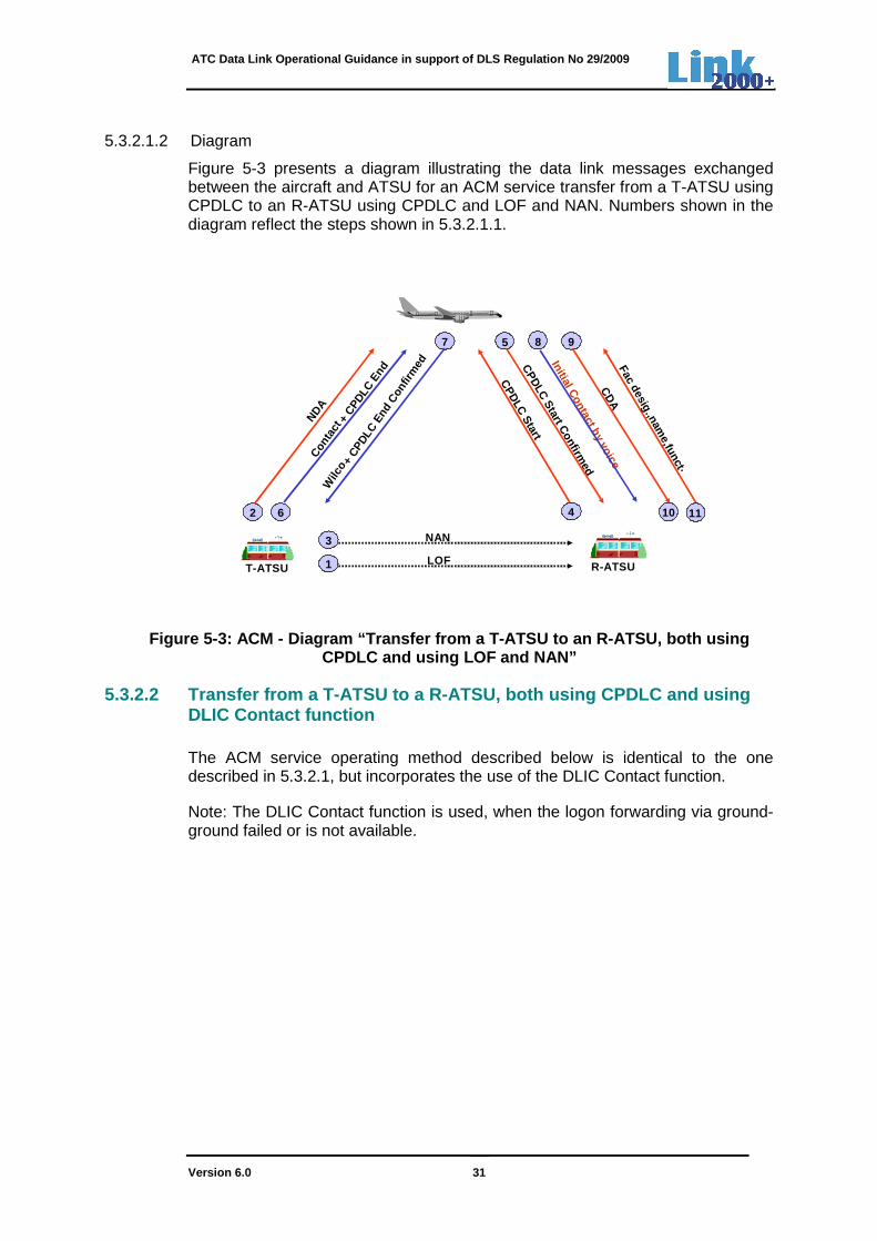
5.3.2.1.2 Diagram
Figure 5-3 presents a diagram illustrating the data link messages exchanged between the aircraft and ATSU for an ACM service transfer from a T-ATSU using CPDLC to an R-ATSU using CPDLC and LOF and NAN. Numbers shown in the diagram reflect the steps shown in 5.3.2.1.1.
Figure 5-3: ACM - Diagram “Transfer from a T-ATSU t o an R-ATSU, both using CPDLC and using LOF and NAN”
5.3.2.2 Transfer from a T-ATSU to a R-ATSU, both us ing CPDLC and using DLIC Contact function The ACM service operating method described below is identical to the one described in 5.3.2.1, but incorporates the use of the DLIC Contact function.
Note: The DLIC Contact function is used, when the logon forwarding via ground-ground failed or is not available.
2
NDA
1 LOF
3 NAN
Conta
ct+
CPDLC
End
6
Wilc
o + CP
DLC
End
Con
firm
ed
7
CPD
LC Start
4
CPD
LC Start C
onfirmed
5
CD
A
9
T-ATSU R-ATSU
10
Initial Contact by voice
8
11
Facdesig.,nam
e,funct .
ATC Data Link Operational Guidance in support of DLS Regulation No 29/2009
Version 6.0 32
5.3.2.2.1 Operating method
The ACM service operating method used for a transfer between a T-ATSU and R-ATSU both using CPDLC and the DLIC Contact function, is as follows:
Step Operating Method
1 The T-ATSU system sends a DLIC Contact Request message to the aircraft
2 T-ATSU system automatically sends a Next Data Authority (NDA) notification to the aircraft system, authorising the aircraft to accept a CPDLC connection request from the R-ATSU
Note 1: The NDA notification is transmitted by the T-ATSU at a prescribed time or distance (determined bilaterally) before the transfer of CPDLC to the R-ATSU
Note 2: The T-ATSU is prohibited from sending the NDA notification until the T-ATSU is the current data authority (CDA)
3 The aircraft system automatically sends a logon request to the R-ATSU system
4 The R-ATSU system attempts to associate the flight data received from the aircraft with the appropriate flight plan
5 The R-ATSU system sends a logon response to the aircraft system
6 The aircraft system sends a contact response to the T-ATSU.
To complete the operating method, follow the operating method in Table 5-3, steps 4 to 11
Table 5-4: ACM - Operating method “Transfer between a T-ATSU and R-ATSU both
using CPDLC and using Contact function”
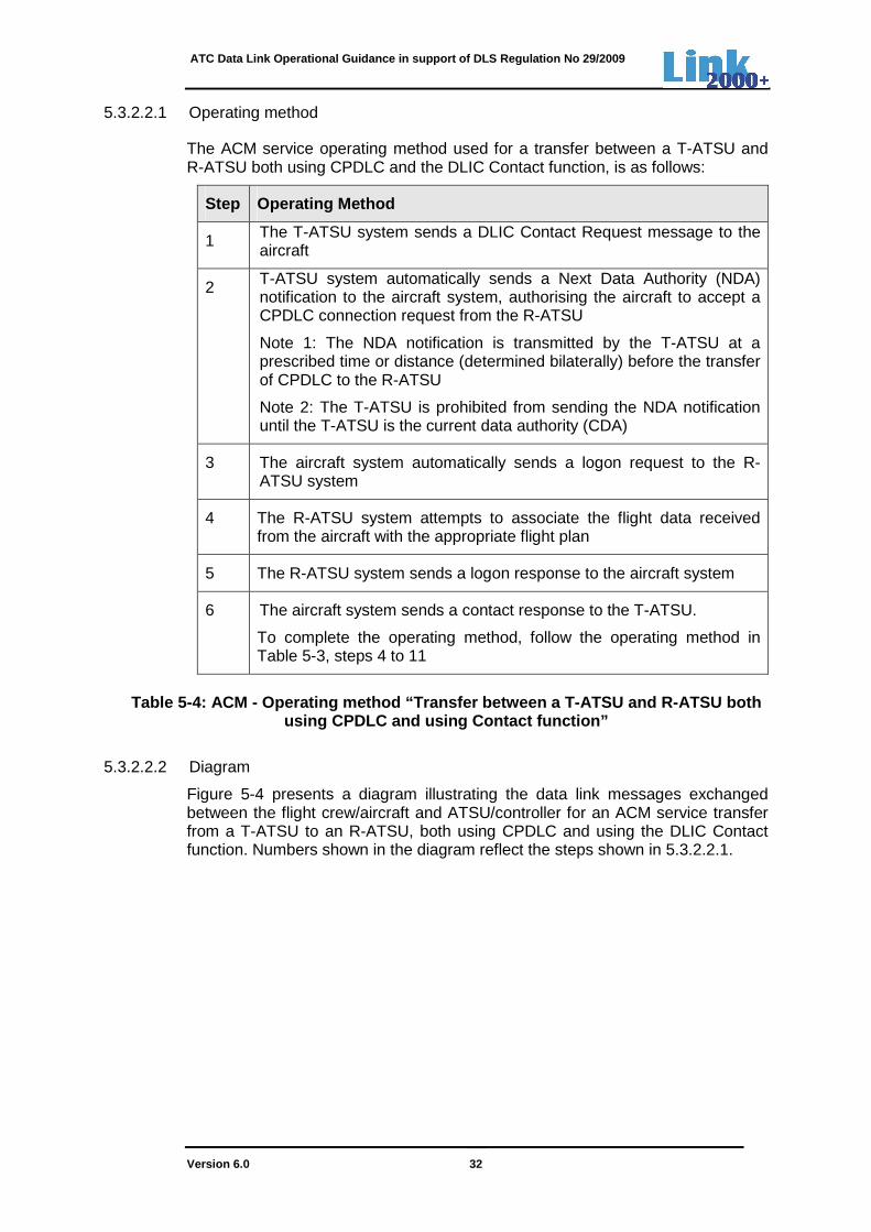
5.3.2.2.2 Diagram
Figure 5-4 presents a diagram illustrating the data link messages exchanged between the flight crew/aircraft and ATSU/controller for an ACM service transfer from a T-ATSU to an R-ATSU, both using CPDLC and using the DLIC Contact function. Numbers shown in the diagram reflect the steps shown in 5.3.2.2.1.
ATC Data Link Operational Guidance in support of DLS Regulation No 29/2009
Version 6.0 33
Con
tact
Req
uest
1
3
Logon Response
4 5
Con
tact
Res
pons
e
Log
on R
equest
6
Requesting ATSU
Specified ATSU
ND
A
2
For remaining steps: see fig 5-3, steps 4-11
Figure 5-4: ACM - Diagram “Transfer from a T-ATSU t o an R-ATSU, both using
CPDLC and using Contact function”
5.3.2.3 Transfer from a T-ATSU not using CPDLC to a R-ATSU using CPDLC In this case, the transfer instruction is provided by voice.
5.3.2.3.1 Operating method
The ACM service operating method for a transfer between a T-ATSU not using CPDLC and R-ATSU using CPDLC is as follows:
Step Operating Method
1 The flight crew sends a logon request to the R-ATSU
Note: The Logon request is transmitted at a prescribed time or distance before the R-ATSU’s area of responsibility is reached (published in the AIC or AIP)
2 The R-ATSU sends the logon response for confirmation
3 The R-ATSU/Initial ATSU system sends a ‘CPDLC-start’ request to the aircraft system
Note: The precise timing of this request is determined locally
4 The aircraft system confirms the connection establishment through a ‘CPDLC-start’ response
5 The aircraft system notifies the R-ATSU that it is the current data authority (CDA)
Note: The aircraft system indicates to the flight crew that the R-ATSU is CDA
ATC Data Link Operational Guidance in support of DLS Regulation No 29/2009
Version 6.0 34
Step Operating Method
6 The T-ATSU controller instructs the flight crew via voice to contact the R-ATSU on its voice channel to the T-ATSU
7 The flight crew reads back the ‘Contact’ instruction by voice
8 Upon read-back, the flight crew tunes the voice channel and contacts the R-ATSU by voice
9 The R-ATSU system notifies the controller when CPDLC has been enabled.
Note: The R-ATSU enables CPDLC upon receipt of a CDA and satisfaction of required local conditions (e.g., ASSUME input of first CPDLC sector, boundary proximity, etc.)
10 Upon receipt of CDA and satisfaction of required local conditions, the R-ATSU system sends a pre-formatted free text message containing the ICAO facility designation, facility name and facility function to the aircraft system for display to the flight crew.
Note: Flight crew should not initiate requests before this pre-formatted free text message is displayed to the flight crew
Table 5-5: ACM - Operating method “Transfer betwee n a T-ATSU not using CPDLC and R-ATSU using CPDLC”
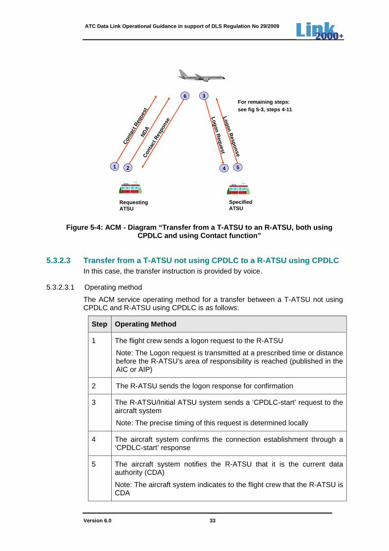
5.3.2.3.2 Diagram
Figure 5-5 presents a diagram illustrating data link messages exchanged between the flight crew/aircraft and ATSU/controller for an ACM service transfer from a non-CPDLC equipped T-ATSU to a CPDLC equipped R-ATSU. Numbers shown in the diagram reflect the steps in 5.3.2.3.1.
4
3
5
9
CPD
LC Start
CPD
LC Start C
onfirmed
CD
A
T-ATSUNot using CPDLC
R-ATSUUsing CPDLC
Conta
ct in
stru
ctio
n by
voi
ce
Readb
ack
of in
stru
ctio
n
6
7 8
Initial Contact by voice
Logon Request
2
1
10
Facdesig.,nam
e,funct .
Logon Response
Figure 5-5: ACM - Diagram ”Transfer from a T -ATSU not using CPDLC to an R-
ATSU using CPDLC”
ATC Data Link Operational Guidance in support of DLS Regulation No 29/2009
Version 6.0 35
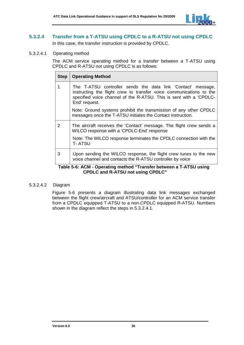
5.3.2.4 Transfer from a T-ATSU using CPDLC to a R-A TSU not using CPDLC In this case, the transfer instruction is provided by CPDLC.
5.3.2.4.1 Operating method
The ACM service operating method for a transfer between a T-ATSU using CPDLC and R-ATSU not using CPDLC is as follows:
Step Operating Method
1 The T-ATSU controller sends the data link ‘Contact’ message, instructing the flight crew to transfer voice communications to the specified voice channel of the R-ATSU. This is sent with a ‘CPDLC-End’ request.
Note: Ground systems prohibit the transmission of any other CPDLC messages once the T-ATSU initiates the Contact instruction.
2 The aircraft receives the ‘Contact’ message. The flight crew sends a WILCO response with a ‘CPDLC-End’ response
Note: The WILCO response terminates the CPDLC connection with the T- ATSU
3 Upon sending the WILCO response, the flight crew tunes to the new voice channel and contacts the R-ATSU controller by voice
Table 5-6: ACM - Operating method “Transfer betwee n a T-ATSU using CPDLC and R-ATSU not using CPDLC”
5.3.2.4.2 Diagram
Figure 5-6 presents a diagram illustrating data link messages exchanged between the flight crew/aircraft and ATSU/controller for an ACM service transfer from a CPDLC equipped T-ATSU to a non-CPDLC equipped R-ATSU. Numbers shown in the diagram reflect the steps in 5.3.2.4.1.

ATC Data Link Operational Guidance in support of DLS Regulation No 29/2009
Version 6.0 36
T-ATSUUsing CPDLC
R-ATSUNot using CPDLC
‘Con
tact
’ ins
truct
ion
by D
L
+
CPDLC
END R
eque
stW
ILCO
+ C
PDLC
END
1
9
Figure 5-6: ACM - Diagram ”Transfer from a T -ATSU using CPDLC to an R- ATSU not using CPDLC”
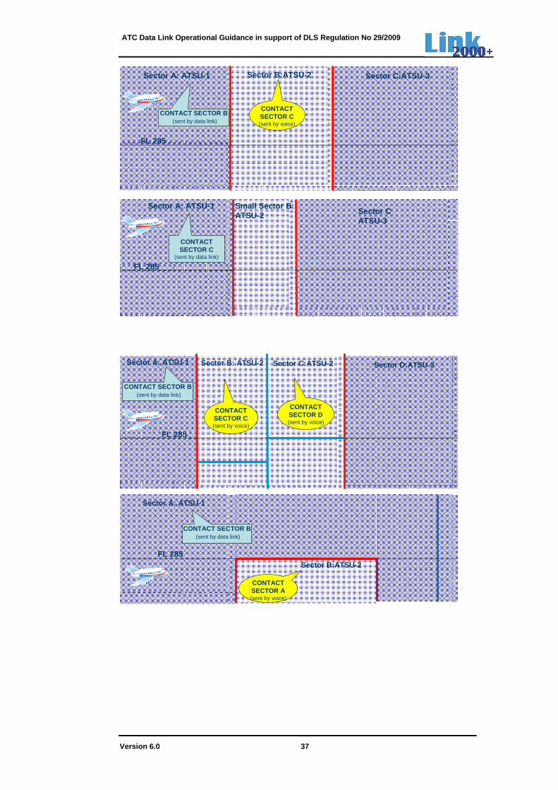
5.3.2.4.3 Examples
Figure 5-7 below depicts 6 scenarios for non-contiguity of airspace of an ATSU regarding the non-use of CPDLC. As explained in section 5.3.2.3 above, a manual logon is again required when the aircraft has been transferred from an ATSU, not using CPDLC, to an ATSU, using CPDLC. This is because upon ATSU transfer, the T-ATSU always terminates the CPDLC connection.
Note1: It may not be expected that an R-ATSU, not using CPDLC, is passing the LOF/NAN message to its adjacent ATSU, using CPDLC.
The first scenario represents the case, where CPDLC is not available for use by ATSU 2. The 2nd scenario depicts the case where the T-ATSU instructs the flight crew to not contact ATSU 2, but instead to directly contact ATSU 3. This may occur for flights (arranged by bilateral agreement) that are crossing an ATSU’s Area of Responsibility during a short period. The last four scenarios represent various cases, where the sector B of ATSU 2 is below FL285.
ATC Data Link Operational Guidance in support of DLS Regulation No 29/2009
Version 6.0 37
FL 285
Sector A: ATSU-1 Sector B:ATSU-2 Sector C:ATSU-3
CONTACT SECTOR B(sent by data link)
CONTACTSECTOR C(sent by voice)
FL 285
Sector A: ATSU-1 Small Sector B:ATSU-2 Sector C
ATSU-3
CONTACT SECTOR C
(sent by data link)
FL 285
Sector A: ATSU-1 Sector B: ATSU-2 Sector C:ATSU-2 Sector D:ATSU-3
CONTACTSECTOR D(sent by voice)
CONTACT SECTOR B(sent by data link)
CONTACTSECTOR C(sent by voice)
FL 285Sector B:ATSU-2
Sector A: ATSU-1
CONTACT SECTOR B(sent by data link)
CONTACTSECTOR A(sent by voice)
ATC Data Link Operational Guidance in support of DLS Regulation No 29/2009
Version 6.0 38
FL 285Sector B:ATSU-2
Sector A:ATSU-1CONTACT SECTOR B
(sent by data link)
CONTACTSECTOR C(sent by voice)
Sector C:ATSU-1
FL 285
Sector B:ATSU-2
Sector C:ATSU-3Sector A:ATSU-1
CONTACT SECTOR C
(sent by data link)
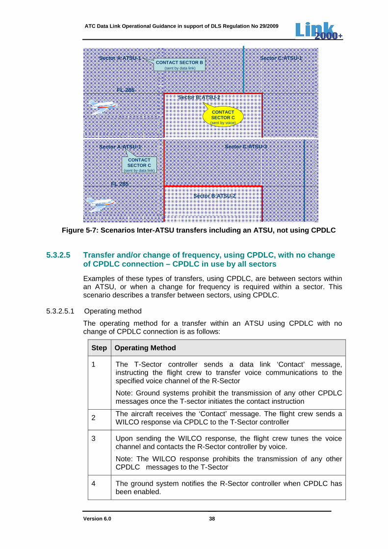
Figure 5-7: Scenarios Inter-ATSU transfers includin g an ATSU, not using CPDLC
5.3.2.5 Transfer and/or change of frequency, using CPDLC, with no change of CPDLC connection – CPDLC in use by all sectors
Examples of these types of transfers, using CPDLC, are between sectors within an ATSU, or when a change for frequency is required within a sector. This scenario describes a transfer between sectors, using CPDLC.
5.3.2.5.1 Operating method
The operating method for a transfer within an ATSU using CPDLC with no change of CPDLC connection is as follows:
Step Operating Method
1 The T-Sector controller sends a data link ‘Contact’ message, instructing the flight crew to transfer voice communications to the specified voice channel of the R-Sector
Note: Ground systems prohibit the transmission of any other CPDLC messages once the T-sector initiates the contact instruction
2 The aircraft receives the ‘Contact’ message. The flight crew sends a WILCO response via CPDLC to the T-Sector controller
3 Upon sending the WILCO response, the flight crew tunes the voice channel and contacts the R-Sector controller by voice.
Note: The WILCO response prohibits the transmission of any other CPDLC messages to the T-Sector
4 The ground system notifies the R-Sector controller when CPDLC has been enabled.
ATC Data Link Operational Guidance in support of DLS Regulation No 29/2009
Version 6.0 39
Note 1: The R-Sector enables CPDLC upon satisfaction of required local conditions (e.g. ASSUME input of first CPDLC sector, boundary proximity, etc.)
Note 2: When there is a voice channel change within the same sector, CPDLC remains enabled
Table 5-7: ACM - Operating method “Transfer within an ATSU, using CPDLC, with no change of CPDLC connection”
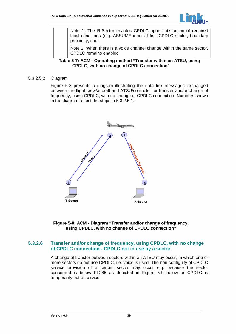
5.3.2.5.2 Diagram
Figure 5-8 presents a diagram illustrating the data link messages exchanged between the flight crew/aircraft and ATSU/controller for transfer and/or change of frequency, using CPDLC, with no change of CPDLC connection. Numbers shown in the diagram reflect the steps in 5.3.2.5.1.
Figure 5-8: ACM - Diagram “Transfer and/or change o f frequency,
using CPDLC, with no change of CPDLC connection”
5.3.2.6 Transfer and/or change of frequency, using CPDLC, with no change of CPDLC connection - CPDLC not in use by a sector
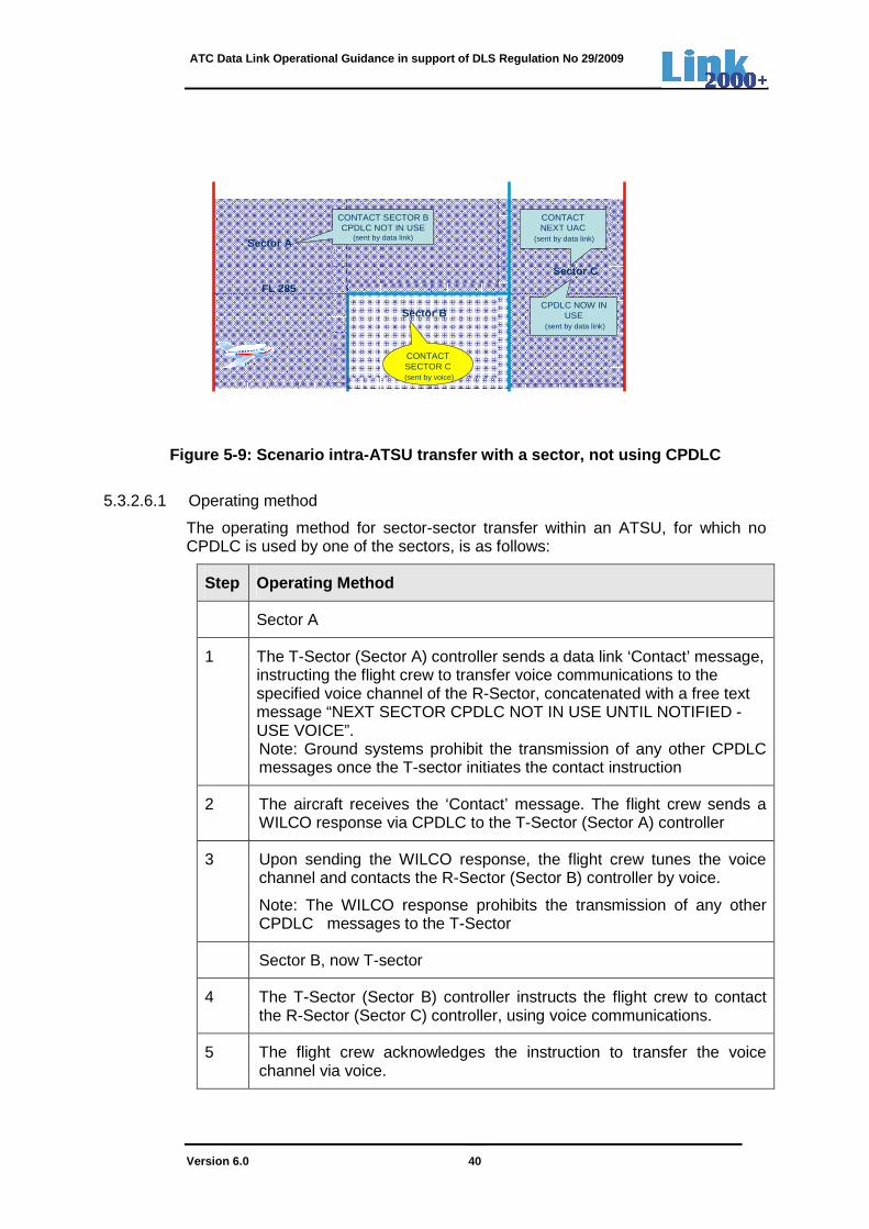
A change of transfer between sectors within an ATSU may occur, in which one or more sectors do not use CPDLC, i.e. voice is used. The non-contiguity of CPDLC service provision of a certain sector may occur e.g. because the sector concerned is below FL285 as depicted in Figure 5-9 below or CPDLC is temporarily out of service.
2
1
Conta
ct
4
Wilc
o
T-Sector R-Sector
Initial Contact by voice
3
ATC Data Link Operational Guidance in support of DLS Regulation No 29/2009
Version 6.0 40
FL 285
Sector A
Sector B
Sector C
CONTACT SECTOR BCPDLC NOT IN USE
(sent by data link)
CONTACTSECTOR C(sent by voice)
CPDLC NOW IN USE
(sent by data link)
CONTACTNEXT UAC
(sent by data link)
Figure 5-9: Scenario intra-ATSU transfer with a sec tor, not using CPDLC
5.3.2.6.1 Operating method
The operating method for sector-sector transfer within an ATSU, for which no CPDLC is used by one of the sectors, is as follows:
Step Operating Method
Sector A
1 The T-Sector (Sector A) controller sends a data link ‘Contact’ message, instructing the flight crew to transfer voice communications to the specified voice channel of the R-Sector, concatenated with a free text message “NEXT SECTOR CPDLC NOT IN USE UNTIL NOTIFIED - USE VOICE”. Note: Ground systems prohibit the transmission of any other CPDLC messages once the T-sector initiates the contact instruction
2 The aircraft receives the ‘Contact’ message. The flight crew sends a WILCO response via CPDLC to the T-Sector (Sector A) controller
3 Upon sending the WILCO response, the flight crew tunes the voice channel and contacts the R-Sector (Sector B) controller by voice.
Note: The WILCO response prohibits the transmission of any other CPDLC messages to the T-Sector
Sector B, now T-sector
4 The T-Sector (Sector B) controller instructs the flight crew to contact the R-Sector (Sector C) controller, using voice communications.
5 The flight crew acknowledges the instruction to transfer the voice channel via voice.

ATC Data Link Operational Guidance in support of DLS Regulation No 29/2009
Version 6.0 41
6 The flight crew tunes the voice channel and contacts the R-Sector (Sector C) controller by voice.
Sector C (R-Sector)
7 The ground system notifies the R-Sector (Sector C) controller when CPDLC has been enabled.
Note: The R-Sector enables CPDLC upon satisfaction of required local conditions (e.g. ASSUME input of first CPDLC sector, boundary proximity, etc.)
8 Once CPDLC is enabled, the R-sector sends a free text message “CPDLC NOW IN USE”.
Table 5-8: ACM - Operating method “Transfer within an ATSU with a sector not using CPDLC
5.3.3 ACM service using 'MONITOR' instruction
The uplink message “MONITOR (UM120)” and downlink message “MONITORING (DM89)” are subject to investigation for operational use.
Given the unresolved issues associated with the ‘MONITOR’ concept, it has been decided to further assess the use of the “MONITOR” and “MONITORING” messages before they can be incorporated for operational use.
Note: Although above messages are not yet able to be used operationally, the potential benefits of the ‘MONITOR’ concept are promising. Therefore, ATSUs are strongly recommended to implement both messages in their ground systems.
5.3.4 Transfer of data communications with open dia logues
5.3.4.1 Open ground-initiated dialogues When a transfer of CPDLC results in a change of data authority and the transfer instruction has been initiated, but not yet sent, the controller transferring the CPDLC is informed of the open ground-initiated dialogues. The controller:
• waits for the responses to the open ground-initiated dialogues and then continues with the transfer instruction, or
• resolves the open ground initiated dialogues (via voice instructions) and then continues with the transfer instructions, or
• ignores the open ground initiated dialogues and continues with the transfer instruction.
Note: When open-ground initiated dialogues are ignored, the ground system closes all outstanding dialogues (See 7.3 for more details).
When there are open ground-initiated dialogues, and the flight crew responds to the transfer instruction with a WILCO, the airborne system cancels all open ground initiated dialogues. When responding with UNABLE or STANDBY, the aircraft system maintains the open dialogues.

ATC Data Link Operational Guidance in support of DLS Regulation No 29/2009
Version 6.0 42
When a transfer of CPDLC does not result in a change of data authority and assuming that the T-sector is not the same as the R-sector, local procedures will define system behaviour, allowing ground systems to cancel or maintain all open ground-initiated dialogues. The airborne system maintains open ground-initiated dialogues.
5.3.4.2 Open air-initiated dialogues When there are open air-initiated dialogues, the ground system closes each of these dialogues with a closure response before sending the transfer instruction.
Note: The closure uplink responses are one of the following:
• UNABLE, or
• REQUEST AGAIN WITH NEXT UNIT (UM237), or
• Concatenated message ‘ERROR’ + REQUEST AGAIN WITH NEXT UNIT (free text), or
• REQUEST AGAIN WITH NEXT UNIT (free text)
When there are open air-initiated dialogues, and the flight crew responds to the transfer instruction with a WILCO, the airborne system cancels all open air initiated dialogues. When responding with UNABLE or STANDBY, the aircraft system maintains the open dialogues.
5.3.5 ACM messages
The ACM service uses CPDLC messages as indicated in Annex A.
5.4 ACL – ATC Clearances
5.4.1 ACL service description
The ACL service allows flight crews and controllers to conduct operational exchanges. The ACL service enables:
• flight crews to send requests and reports to controllers;
• controllers to issue clearances, instructions and notifications to flight crew.
The ACL service will only be available after successful completion of the ACM service.
For the purposes of this document, only the following examples are described:
• flight crew request with controller clearance response;
• flight crew request with controller UNABLE response;
• flight crew request with controller STANDBY response;
• controller clearance with flight crew WILCO response;
• controller clearance with flight crew UNABLE response;
• controller clearance with flight crew STANDBY response.

ATC Data Link Operational Guidance in support of DLS Regulation No 29/2009
Version 6.0 43
5.4.2 ACL operating methods
The ACL operating method conforms to the existing voice communications operating method.
5.4.2.1 Flight crew request with controller clearan ce response
5.4.2.1.1 Operating method:
The ACL operating method for a flight crew initiated request and controller clearance response is as follows:
Step Operating Method
1 The flight crew sends a request initiating a dialogue
2 The controller is notified upon receipt of the request
3 The controller responds with a clearance
Note: The clearance instruction may be different from the request
4 The flight crew is notified upon receipt of the clearance message
5 Upon receipt of the clearance message the flight crew responds with WILCO or UNABLE
Note: Either the WILCO or UNABLE response closes the dialogue
6 The controller is notified upon receipt of the WILCO or UNABLE response
Table 5-9: ACL - Operating method “Flight crew initiated request and controller clearance response”
5.4.2.1.2 Diagram
Figure 5-10 provides a diagram illustrating the data link messages exchanged between the flight crew and controller for flight crew ACL requests with a controller clearance response. Numbers shown in the diagram reflect the steps in 5.4.2.1.1.
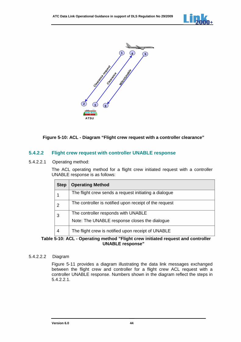
ATC Data Link Operational Guidance in support of DLS Regulation No 29/2009
Version 6.0 44
Figure 5-10: ACL - Diagram “Flight crew request wit h a controller clearance”
5.4.2.2 Flight crew request with controller UNABLE response
5.4.2.2.1 Operating method:
The ACL operating method for a flight crew initiated request with a controller UNABLE response is as follows:
Step Operating Method
1 The flight crew sends a request initiating a dialogue
2 The controller is notified upon receipt of the request
3 The controller responds with UNABLE
Note: The UNABLE response closes the dialogue
4 The flight crew is notified upon receipt of UNABLE
Table 5-10: ACL - Operating method ”Flight crew initiated request and controller UNABLE response”
5.4.2.2.2 Diagram
Figure 5-11 provides a diagram illustrating the data link messages exchanged between the flight crew and controller for a flight crew ACL request with a controller UNABLE response. Numbers shown in the diagram reflect the steps in 5.4.2.2.1.
3
1
Cle
aran
ce re
ques
t
5
Cle
aran
ceATSU
Wilc
o /Una
ble
4
26

ATC Data Link Operational Guidance in support of DLS Regulation No 29/2009
Version 6.0 45
Figure 5-11: ACL - Diagram “Flight crew request wit h a controller UNABLE response”
5.4.2.3 Flight crew request with controller STANDBY response
5.4.2.3.1 Operating method:
The ACL operating method for a flight crew initiated request with a controller STANDBY response is as follows:
Step Operating Method
1 The flight crew sends a request initiating a dialogue
2 The controller is notified upon receipt of the request
3 The controller responds with STANDBY
4 Flight crew is notified upon the receipt of STANDBY
Note: The STANDBY message does not close the dialogue
5 The controller may respond with a clearance or UNABLE
If the controller responds with a clearance, follow Table 5-7, steps 3 to 6.
If the controller responds with UNABLE, follow Table 5-8, steps 3 and 4.
Table 5-11: ACL - Operating method “Flight crew initiated request and controller STANDBY response”
3
1
Clear
ance
requ
est
Unabl
e
ATSU
4
2
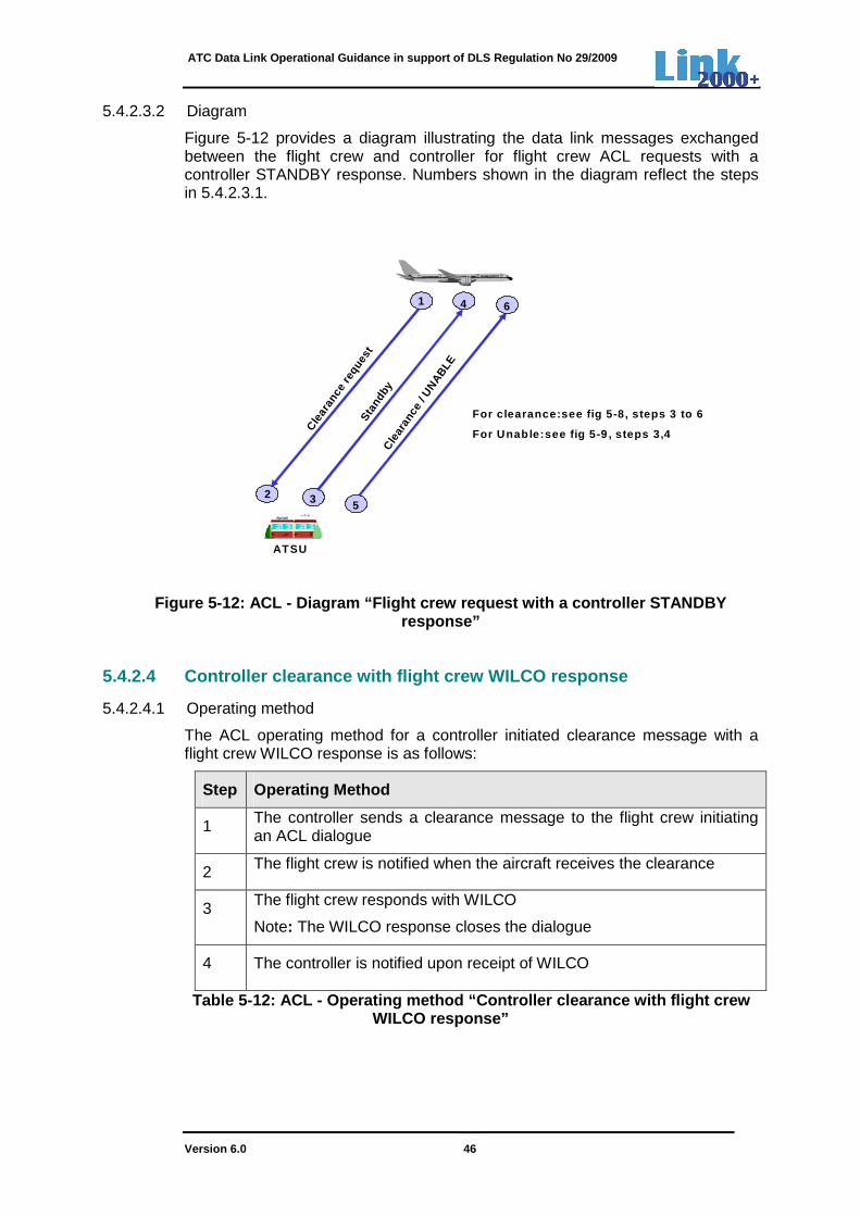
ATC Data Link Operational Guidance in support of DLS Regulation No 29/2009
Version 6.0 46
5.4.2.3.2 Diagram
Figure 5-12 provides a diagram illustrating the data link messages exchanged between the flight crew and controller for flight crew ACL requests with a controller STANDBY response. Numbers shown in the diagram reflect the steps in 5.4.2.3.1.
Figure 5-12: ACL - Diagram “Flight crew request wit h a controller STANDBY response”
5.4.2.4 Controller clearance with flight crew WILCO response
5.4.2.4.1 Operating method
The ACL operating method for a controller initiated clearance message with a flight crew WILCO response is as follows:
Step Operating Method
1 The controller sends a clearance message to the flight crew initiating an ACL dialogue
2 The flight crew is notified when the aircraft receives the clearance
3 The flight crew responds with WILCO
Note: The WILCO response closes the dialogue
4 The controller is notified upon receipt of WILCO
Table 5-12: ACL - Operating method “Controller cle arance with flight crew WILCO response”
3
1C
lear
ance
requ
est
Stan
dby
ATSU
4
2
For c learance:see fig 5-8, steps 3 to 6
For Unab le:see fig 5-9 , steps 3,4
Cle
aran
ce /
UN
ABLE
5
6
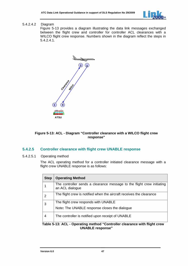
ATC Data Link Operational Guidance in support of DLS Regulation No 29/2009
Version 6.0 47
5.4.2.4.2 Diagram Figure 5-13 provides a diagram illustrating the data link messages exchanged between the flight crew and controller for controller ACL clearances with a WILCO flight crew response. Numbers shown in the diagram reflect the steps in 5.4.2.4.1.
Figure 5-13: ACL - Diagram “Controller clearance wi th a WILCO flight crew response”
5.4.2.5 Controller clearance with flight crew UNABL E response
5.4.2.5.1 Operating method
The ACL operating method for a controller initiated clearance message with a flight crew UNABLE response is as follows:
Step Operating Method
1 The controller sends a clearance message to the flight crew initiating an ACL dialogue
2 The flight crew is notified when the aircraft receives the clearance
3 The flight crew responds with UNABLE
Note: The UNABLE response closes the dialogue
4 The controller is notified upon receipt of UNABLE
Table 5-13: ACL - Operating method “Controller cle arance with flight crew UNABLE response”
3
1
Clear
ance
ATSU
Wilc
o
2
4
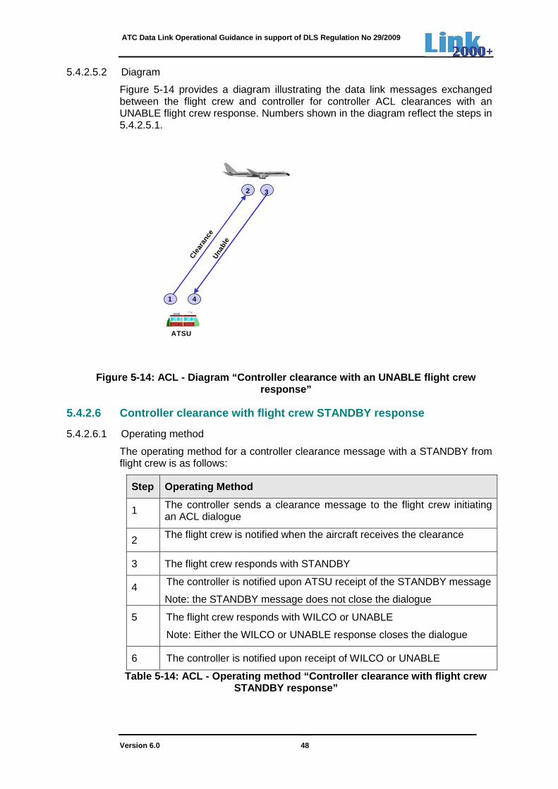
ATC Data Link Operational Guidance in support of DLS Regulation No 29/2009
Version 6.0 48
5.4.2.5.2 Diagram
Figure 5-14 provides a diagram illustrating the data link messages exchanged between the flight crew and controller for controller ACL clearances with an UNABLE flight crew response. Numbers shown in the diagram reflect the steps in 5.4.2.5.1.
Figure 5-14: ACL - Diagram “Controller clearance wi th an UNABLE flight crew response”
5.4.2.6 Controller clearance with flight crew STAND BY response
5.4.2.6.1 Operating method
The operating method for a controller clearance message with a STANDBY from flight crew is as follows:
Step Operating Method
1 The controller sends a clearance message to the flight crew initiating an ACL dialogue
2 The flight crew is notified when the aircraft receives the clearance
3 The flight crew responds with STANDBY
4 The controller is notified upon ATSU receipt of the STANDBY message
Note: the STANDBY message does not close the dialogue
5 The flight crew responds with WILCO or UNABLE
Note: Either the WILCO or UNABLE response closes the dialogue
6 The controller is notified upon receipt of WILCO or UNABLE
Table 5-14: ACL - Operating method “Controller cle arance with flight crew STANDBY response”
3
1
Clear
ance
ATSU
Una
ble
2
4

ATC Data Link Operational Guidance in support of DLS Regulation No 29/2009
Version 6.0 49
5.4.2.6.2 Diagram
Figure 5-15 provides a diagram illustrating the data link messages exchanged between the flight crew and controller for ACL clearances with STANDBY. Numbers shown in the diagram reflect the steps in 5.4.2.6.1.
Figure 5-15: ACL – Diagram ”Controller Clearance wi th STANDBY”
5.4.3 ACL messages
The ACL service uses CPDLC messages as indicated in Annex A.
5.5 AMC - ATC Microphone Check
5.5.1 AMC service description
The AMC service allows controllers to send an instruction to CPDLC capable aircraft on a given frequency, at the same time, in order to instruct flight crews to verify that their voice communication equipment is not blocking a given voice channel. This instruction will be issued only to those aircraft under his control. The AMC service will be available to controllers only after use of the ACM service.
5.5.1.1 AMC operating method
The AMC operating method is as follows:
Step Operating Method
1 An instruction to check a blocked microphone is sent to all CPDLC capable aircraft under the responsibility of the controller
3
1
Clear
ance
ATSU
Wilc
o or
Una
ble
2
Stan
dby
4
5
6

ATC Data Link Operational Guidance in support of DLS Regulation No 29/2009
Version 6.0 50
Step Operating Method
2 The flight crews are notified upon aircraft receipt of the AMC instruction The flight crews check their communication equipment to:
- determine if they are responsible for the blockage, and
- correct the problem, if applicable
Table 5-15: AMC Operating method
5.5.1.2 Diagram Figure 5-16 provides a diagram illustrating the data link exchanges between the flight crew/aircraft and ATSU/controller for the AMC service. Numbers shown in the diagram reflect the steps in 5.5.1.1
Figure 5-16: AMC Diagram
5.5.1.3 AMC message The message that is to be used for the AMC service is described in Annex A.
5.6 Timers
For ACL, ACM and AMC messages, the ATN Baseline1 INTEROP Standard (ED110-B) [6] defines the implementation of the following three timers in ground- and aircraft systems:
• Technical response (LACK) timer (tr)
• Expiration timer-initiator (tts)
• Expiration timer-responder (ttr)
1
Che
ck S
tuck
Mic
Sector
22
Che
ck S
tuck
Mic
Aircraft XAircraft A
ATC Data Link Operational Guidance in support of DLS Regulation No 29/2009
Version 6.0 51
In addition, ED-110B specifies the use of a latency time monitor mechanism to monitor the time of reception of a message.
In accordance with ED110B and the EUROCONTROL Specification:
• For aircraft systems, implementation of the expiration timer-responder (ttr), the LACK timer (tr) and the latency time monitor is mandatory. Aircraft systems are not required to implement the expiration timer–initiator (tts).
• Ground systems are required to implement the expiration timer–initiator (tts), LACK timer (tr) and expiration timer-responder (ttr). Ground systems are not required to implement the latency time monitor.
5.6.1 Technical response (LACK) timer
The purpose of the LACK message is to inform the controller that the uplinked message was received and processed by the aircraft system, and that it was found acceptable for display to the flight crew.
In addition, the LACK may be used to monitor the performance of the air-ground communications network.
Each time the controller sends an operational message, the aircraft system returns a logical acknowledgement (LACK).
Note 1: Ground systems do not request a LACK for the messages ERROR (UM159), Service Unavailable (UM162) and LACK (UM227).
Note 2: Ground systems are not required to request a LACK for the AMC instruction.
5.6.1.1 If used, the LACK timer value should be set by the ground system at 40 seconds. If the ground system does not receive a LACK within 40 seconds, the controller will be notified. Note: Local implementers may decide whether the controller is notified on the receipt of each LACK (positive feedback) or is only notified upon a LACK time out (negative feedback).
5.6.1.2 When a LACK is received after expiry of the LACK timer, the LACK may be discarded.
5.6.2 Latency time monitor
Aircraft systems The latency time monitor compares the time of transmission of an uplinked CPDLC message (from the CPDLC time-stamp) with the time of reception. If the permitted latency time is exceeded, then the CPDLC message becomes invalid for the flight crew. After this time, the CPDLC message may have lost its operational meaning and the time to act upon the received CPDLC message may have become too short for the flight crew. The aircraft system behaviour is intended to ensure that a delayed CPDLC message is not left active with the flight crew for a significant period of time after the dialogue has been closed at the ground side.
5.6.2.1 The latency value is set in aircraft systems at 40 seconds.
ATC Data Link Operational Guidance in support of DLS Regulation No 29/2009
Version 6.0 52
5.6.2.2 Upon activation of the latency monitor, the aircraft system:
either • does not present the CPDLC message to the flight crew and automatically
downlinks an error message ‘UPLINK DELAYED IN NETWORK AND REJECTED; RESEND OR CONTACT BY VOICE’ for display to the controller. The controller reverts to voice as described in procedure 6.8.2.
or
• presents the CPDLC message to the flight crew with an appropriate warning. The flight crew reverts to voice as described in procedure 6.8.2.
Ground systems If an ANSP has implemented the latency check (not required), a similar behaviour
exists as described above. When the flight crew sends a CPDLC request to the ground, the CPDLC message becomes invalid for the controller when it is received after the allowed limit. If the permitted latency time is exceeded, then the downlinked request is either discarded, and an ERROR response sent, or else the message is displayed to the controller with an appropriate warning.
5.6.2.3 If used, the message latency is set by ground systems at 40 seconds.
5.6.2.4 Upon activation of the latency monitor, the ground system:
either
• does not present the CPDLC message to the controller and automatically uplinks an error message ‘DOWNLINK DELAYED - USE VOICE’ for display to the flight crew. The flight crew reverts to voice as described in procedure 6.8.2.
or
• presents the CPDLC message with the timestamp to the controller. The controller reverts to voice as described in procedure 6.8.2.
5.6.3 Expiration timers
Expiration timers are used for messages requiring an operational response to prevent that a data link dialogue becomes open-ended. Two expiration timers exist:
• Expiration timer-initiator (tts);
• Expiration timer-responder (ttr).
Different values are specified, depending on whether the dialogue is controller or flight crew initiated.
5.6.3.1 Controller initiated dialogues 5.6.3.1.1 When the controller uplinks a CPDLC message, requiring an operational
response, the ground system starts the expiration timer-initiator (tts).

ATC Data Link Operational Guidance in support of DLS Regulation No 29/2009
Version 6.0 53
5.6.3.1.2 The timer value for the operational response to be received is set at 120 seconds.
5.6.3.1.3 The timer-initiator (tts) expires, if no operational response has been received by the ground system within 120 seconds. The controller is notified and reverts to voice to resolve the situation (see procedure in 6.8.2).
The dialogue is closed locally by the ground system, ensuring that the dialogue doesn’t remain open at the ground side.
5.6.3.1.4 When the aircraft system receives the message, it starts the expiration timer-responder (ttr).
5.6.3.1.5 The timer value for the response to be sent is set at 100 seconds.
5.6.3.1.6 The timer-responder (ttr) expires, if the flight crew fails to respond within 100
seconds. The flight crew is notified and reverts to voice to complete the dialogue (see procedure in 6.8.2). The aircraft system closes the dialogue and downlinks an error response ‘AIRSYSTEM TIME-OUT’. The error response ensures that the dialogue will also be closed at the ground side, if the timer-initiator (tts) has not expired. Note: In normal circumstances, the timer-responder (ttr) should expire before the timer-initiator times out.
5.6.3.1.7 If the flight crew responds to a clearance with a STANDBY, the aircraft and ground timers are re-started.
Figure 5-17 depicts the LACK, and expiration timers used in a controller-initiated dialogue.
LACK
LACK
LACK
ttr=100s
UmUm
Response
Response
tr=40s
Aircraft/flight crew Comms. Service ATSU/controller
tr=40s
LACK
tts=120s
Figure 5-17: Timers used in a controller-initiated dialogue

ATC Data Link Operational Guidance in support of DLS Regulation No 29/2009
Version 6.0 54
5.6.3.2 Flight crew-initiated dialogues.
5.6.3.2.1 When the flight crew downlinks a request, requiring an operational response, and when implemented, the aircraft system starts the expiration timer-initiator (tts).
5.6.3.2.2 If used, the timer value for the operational response to be received is set at 270 seconds.
5.6.3.2.3 The timer-initiator (tts) expires, if no operational response has been received by the aircraft system within 270 seconds. The flight crew is notified and reverts to voice to resolve the situation (see procedure in 6.8.2). The dialogue is closed locally by the aircraft system, ensuring that the dialogue doesn’t remain open at the aircraft side.
5.6.3.2.4 When the ground system receives the request, then it starts the expiration timer-responder (ttr).
5.6.3.2.5 The timer value for this response to be sent is set at 250 seconds.
5.6.3.2.6 The timer-responder (ttr) expires, if the controller fails to respond within 250 seconds. The controller is notified and reverts to voice complete the dialogue (see procedure in 6.8.2). The ground system closes the dialogue and uplinks an error response ‘ATC TIME OUT – REPEAT REQUEST’. The error response ensures that the dialogue will also be closed at the aircraft side, if the timer-initiator (tts) has not expired.
Note: In normal circumstances, the timer-responder (ttr) should expire before the timer-initiator times out.
5.6.3.1.7 If the controller responds to a request with a STANDBY, the aircraft and ground timers are re-started.
Figure 5-18 depicts the LACK, and expiration timers used in a flight crew-initiated dialogue.
LACK
LACKLACKtts =270s ttr=250s
DmDm
ResponseResponse
tr =40s
Aircraft/flight crew Comms. Service ATSU/controller
tr=40s
LACK
Figure 5-18: Timers used in a flight crew-initiated dialogue
ATC Data Link Operational Guidance in support of DLS Regulation No 29/2009
Version 6.0 55
6. CPDLC PROCEDURES
The procedures listed below are a collection of CPDLC procedures, relevant to implementers and controllers, cited from ICAO documents 4444 (PANS-ATM), Annex 10 (Communication Procedures), 7030/5 (Regional Supplementary Procedures-EUR Region), and EUROCAE documents ED-120 (Continental SPR Standard) and ED-110B (ATN B1 INTEROP Standard). The procedures below should be used in conjunction with GOLD ED 2.0 [15].
In addition, the OFG has recommended some procedures to support the use of CPDLC operations. These recommended procedures are enumerated with the “OFG-Recom-# “ tag.
It should be noted that some procedures are exemplified with examples (highlighted in blue) or accompanied by a note. These examples or notes are not part of the cited documents, but are provided for clarification purposes.
6.1 General
6.1.1 Where applicable, the communication procedures for the provision of CPDLC shall be in line with ICAO Annex 10, Volume III, Part I, Chapter 3.
CPDLC message element intent and text and associated procedures are, in general, consistent with ICAO Doc 4444 PANS-ATM Chapter 12 - Phraseologies. It is, however, recognised that the CPDLC message set and the associated procedures differ somewhat from the voice equivalent used because of the differences between the two media; one being direct-speech and the other an exchange of data, the latter of which can be displayed and/or printed.
PANS-ATM 14.1.5
6.1.2 Information concerning CPDLC message element subsets utilized and, if applicable, any additional preformatted free text messages shall be published in aeronautical information circulars or publications.
Annex 10 V2- 8.2.9.5.3
6.1.3 CPDLC shall be established in sufficient time to ensure that the aircraft is communicating with the appropriate ATC unit. Information concerning when and, where applicable, where, the air or ground systems should establish CPDLC, shall be published in Aeronautical information Circulars or Publications.
Annex 10 V2- 8.2.8.2
PANS-ATM 14.2.1
6.1.4 The pilot shall be able to identify the air traffic control unit providing the air traffic control service at any time while the service is being provided.
Annex 10 V2- 8.2.8.4
6.2 Flight planning provisions
6.2.1 Capabilities comprise the following elements: a) presence of relevant serviceable equipment on board the aircraft;
PANS-ATM Appendix 2
ATC Data Link Operational Guidance in support of DLS Regulation No 29/2009
Version 6.0 56
b) equipment and capabilities commensurate with flight crew qualifications; and
c) where applicable, authorization from the appropriate authority.
Item 10 – Equipment
6.2.2 Operators of CPDLC capable aircraft, equipped with either FANS 1/A or ATN-B1, shall insert in Item 10 of the ICAO flight plan form, one or more of the following items:
J1 for CPDLC-ATN-B1 VDLM2
J2 for CPDLC-FANS 1/A HFDL
J3 for CPDLC-FANS 1/A VDL MODE A
J4 for CPDLC-FANS 1/A VDL MODE 2
J5 for CPDLC-FANS 1/A SATCOM (INMARSAT)
J6 for CPDLC-FANS 1/A SATCOM (MTSAT)
J7 for CPDLC-FANS 1/A SATCOM (Iridium)
PANS-ATM Appendix 2
Item 10 – Equipment
6.2.3 Operators of CPDLC capable aircraft, equipped with independent FANS 1/A and ATN-B1, shall insert in Item 10 of the ICAO flight plan form item J1 and one or more of the items J2 to J7, as applicable.
Not specified in PANS-ATM
TBD at OPLINKP
6.2.4 Operators of CPDLC capable aircraft, equipped with integrated FANS 1/A and ATN-B1 shall insert in:
- Item 10 of the ICAO flight plan form item J1 and one or more of the items J2 to J7, and
- Item 18 shall specify the equipment carried, preceded by COM/ followed by INTEGRATED.
Not specified in PANS-ATM
TBD at OPLINKP
6.2.5 Flights, planning to use CPDLC ATN-B1, shall include in Item 18 of the flight plan the indicator CODE/ followed by the 24-bit aircraft address (expressed in the form of alphanumerical code of six hexadecimal characters).
Example: CODE/ F00001
PANS-ATM Appendix 2 Item 18 – Equipment
6.2.6 Flights, planning to use CPDLC FANS 1/A, shall include in Item 18 of the flight plan the indicator REG/ followed by the nationality or common mark and registration mark of the aircraft, if different from the aircraft identification in Item 7.
PANS-ATM Appendix 2
Item 18 – Equipment
6.2.7 For flights, conducted wholly or partly in the EUR CPDLC airspace specified in 3.3.1.1 (of Doc 7030/5), and not equipped with CPDLC-ATN-B1, but which have been granted an exemption, either automatic or by EC Decision, shall include in Item 10A the letter Z and in Item18 of the flight plan the indicator DAT/CPDLCX.
7030/5, Amendment EUR/NAT-S 09/03 – EUR 2-4 and 3-2
6.2.8 For a flight operating based on a repetitive flight plan (RPL), during which the pilot intends to use CPDLC, a modification message (CHG) should be submitted to indicate that the flight is capable of CPDLC, in accordance with 6.2.2, 6.2.3 and 6.2.4.
OFG-Recom-1

ATC Data Link Operational Guidance in support of DLS Regulation No 29/2009
Version 6.0 57
6.2.9 When there is a change to the CPDLC capability status for a flight planned to operate in the area specified in section 0, the operator should send a modification message (CHG) with the appropriate indications in the relevant items of the ICAO flight plan form, including any change to the aircraft address. A modification message for the day of operation should be sent not earlier than 20 hours before the estimated off-block time.
OFG-Recom-2
6.2.10 To avoid an automatic rejection of the logon/notification, the pilot should ensure that the flight number and Destination/Arrival parameters contained in the logon message are exactly the same as the flight number and Destination/Arrival parameters filed in the flight plan.
OFG-Recom-3
6.3 Testing of CPDLC
6.3.1 Where the testing of CPDLC with an aircraft could affect the air traffic services being provided to the aircraft, coordination shall be effected prior to such testing.
Annex 10 V2-8.2.13
PANS-ATM 14.3.10
6.4 Transfer of CPDLC
6.4.1 Time and place of CPDLC Transfer
Note: The transfer of CPDLC between two adjacent ATC units (Current Data Authority-CDA, Next Data Authority-NDA ) consists of: a) The initiation of CPDLC by the accepting ATC unit [NDA] and, b) The termination of CPDLC by the transferring ATC Unit [CDA]
6.4.1.1 When CPDLC is transferred, the transfer of voice communications and CPDLC shall commence concurrently.
Note: The transfer of CPDLC will normally be performed in a manner transparent to the controller. The use of the ground-ground forwarding messages (LOF and NAN) or DLIC-Contact will be automatically triggered by the system, as described in section 7.7
Annex 10 V2-8.2.9.6.1
PANS-ATM 14.3.3.1
6.4.1.2 When an aircraft is transferred from an ATC unit where CPDLC is available to an ATC unit where CPDLC is not available, CPDLC termination shall commence concurrent with the transfer of voice communications.
Annex 10 V2-8.2.9.6.2
PANS-ATM 14.3.3.2
6.4.1.3 All operational details with respect to the transfer of communications for flights using CPDLC (e.g. the time and/or position where the transfer of data link is initiated) should be reflected accordingly in Letters of Agreement established between the ATC units concerned.
OFG-Recom-4
6.4.2 Transfer of CPDLC when open dialogues exist
6.4.2.1 When a transfer of CPDLC results in a change of data authority, and there are still messages for which the closure response has not been received (i.e. messages outstanding), the controller transferring the CPDLC shall be informed.
Annex 10 V2-8.2.9.6.3
PANS-ATM 14.3..3.3
ATC Data Link Operational Guidance in support of DLS Regulation No 29/2009
Version 6.0 58
6.4.2.2 When the controller decides to transfer the aircraft without receiving pilot responses to any uplink message(s) outstanding, the controller should revert to voice communications to clarify any ambiguity associated with the message(s) outstanding.
PANS-ATM 14.3.3.3.2
6.4.3 Inability to contact the assigned voice communication channel
6.4.3.1 When the pilot is unable to contact on the assigned voice communication channel when instructed to do so by the controller via CPDLC, the pilot should revert to the voice communication channel of the transferring ATC unit for instructions.
OFG-Recom-5
6.5 Construction of CPDLC messages
6.5.1 The text of messages shall be composed in standard message format (e.g. CPDLC message set), in plain language or in abbreviations and codes, as prescribed in Annex 10, paragraph 3.7. Plain language shall be avoided when the length of the text can be reduced by using appropriate abbreviations and codes. Non-essential words and phrases, such as expressions of politeness, shall not be used.
Annex 10 V2-8.1.1.1
6.5.2 Any exchange of CPDLC messages shall allow only one open dialogue of the same type with the same aircraft at any given time.
Note: Appropriate consideration should be given to system support procedures, so as to not allow the initiation of clearance dialogues with the same recipient, already involved in the same type of clearance dialogue Example 1: If a level instruction has been sent to an aircraft via CPDLC, a subsequent level instruction to the same aircraft can be initiated only if the CPDLC dialogue pertaining to the initial level instruction has been closed. If action is required before the dialogue is closed, the communications should be reverted to voice. Example 2: When the ground system receives a downlink request and there is an existing open uplink, containing the same type, the downlink request is discarded.
ED-120, 5.2.2.3
ED-110B, Vol I, 3.3.8.1
6.5.3 The controller or pilot shall construct CPDLC messages using the defined message set, a free text message or a combination of both.
Note: Per ED-110B [6], it is not recommended, except when appended to an ERROR message element, to use free text messages for CPDLC exchanges. This, to reduce the possibility of misinterpretation and ambiguity.
PANS-ATM 14.3.1
6.5.3.1 When considered necessary by the appropriate ATS authority, additional pre-formatted free text messages shall be made available to the controller for those occasions where the CPDLC message set contained in the PANS-ATM does not provide for specific requirements. In such cases, a list of pre-formatted free text messages shall be established by the appropriate ATS authority, in consultation with operators and other ATS authorities that may be concerned
Annex 10 V2-8.2.9.5.2
ATC Data Link Operational Guidance in support of DLS Regulation No 29/2009
Version 6.0 59
6.5.3.2 The use of free text messages by controllers or pilots, other than pre-formatted free text messages referred to in PANS ATM, paragraph 11.4.1.4, or ANNEX 10, paragraph 8.2.9.5.2, should be avoided.
Note 1.- Whilst it is recognized that non-routine and emergency situations may necessitate the use of free text, particularly when voice communication has failed, the avoidance of utilizing free text messages is intended to reduce the possibility of misinterpretation and ambiguity
Note 2.- In support of the recommendation in ED-110B on ‘free text’, some aircraft manufactures and ACCs don’t’ allow the pilot or controller to enter free text on the HMI.
Annex 10 V2-8.2.11
6.5.4 When CPDLC is being used, and the intent of the message is included in the CPDLC message set contained in PANS-ATM, Appendix 5, the associated message shall be used.
Annex 10 V2-8.2.9.1.1
PANS-ATM 14.3.1.2
6.5.5 The composition of a CPDLC message shall not exceed five message elements, only two of which may contain the route clearance variable.
Annex 10 V2 8.2.9.2
6.5.5.1 The use of long messages or messages with multiple clearance elements, multiple clearance request elements, or messages with a combination of clearances and information should be avoided where possible.
Annex 10 V2-8.2.9.2.1
PANS-ATM 14.3.1.1
6.5.5.2 Whenever sending a clearance or an instruction via CPDLC, the conditions pertaining to that clearance or instruction (e.g. vertical speed control) should be included in the same CPDLC message.
OFG-Recom-6
6.5.6 Multi-element messages
Note: For detailed guidance on the use of multi-element messages, see section 11.
6.5.6.1 When a multi-element message requires a response, and the response is in the form of a single message element, the response shall apply to all message elements.
Example: in a multi-element message containing CLIMB TO FL310 MAINTAIN MACH .80, a WILCO response applies to and indicates compliance with both elements of the message.
Annex10 V2-8.2.9.3.3.1
PANS-ATM 14.3.2.3.2
6.5.6.2 When a single message element clearance or any part of a multi-element clearance message cannot be complied with, the pilot shall send an “UNABLE” response for the whole message.
Response indicates that the pilot will not comply with any of the message elements
DM 01 UNABLE – The instruction cannot be complied with.
Example: ATC has sent a multi-element message containing: CLIMB TO FL310 MAINTAIN MACH .80 If the pilot cannot climb as requested or cannot maintain Mach .80, the reply will be: UNABLE
Annex10 V2-8.2.9.3.3.2
PANS-ATM 14.3.2.3.3
ATC Data Link Operational Guidance in support of DLS Regulation No 29/2009
Version 6.0 60
6.5.6.3 The controller shall respond with an “UNABLE” message that applies to all elements of the request when no element(s) of a single or multi-element clearance request can be approved. The current clearance(s) shall not be restated.
Annex10 V2-8.2.9.3.3.3
PANS-ATM 14.3.2.3.4
6.5.6.4 When all elements of a single or multi-element clearance request can be accommodated, the controller shall respond with clearances corresponding to each element of the request. This response should be a single uplink message. Note — For example, whilst messages containing multi-element clearance requests are to be avoided, a multi-element downlink message containing the indicated message elements: REQUEST DIRECT BCN REQUEST CLIMB TO FL350 REQUEST MACH 0.80 could be responded to with CLEARED DIRECT TO BCN CLIMB TO FL350 MAINTAIN MACH 0.80
Annex10 V2-8.2.9.3.3.5
PANS-ATM 14.3.2.3.6
6.5.6.5 When a multi-element clearance request can only be partially accommodated, the controller shall respond with an UNABLE message applying to all the message elements of the request and, if appropriate, include a reason and/or a clearance expectation. Note — A separate CPDLC message (or messages) may subsequently be transmitted to respond to those elements that can be accommodated.
Annex10 V2-8.2.9.3.3.4
PANS-ATM 14.3.2.3.5
6.5.6.6 When a CPDLC message contains more than one message element and the response attribute for the message is Y, when utilized, the single response message shall contain the corresponding number of replies and in the same order.
Example: a multi-element uplink message containing REPORT PRESENT LEVEL STATE-TOP-OF-DESCENT
could be responded to with
PRESENT LEVEL 310 TOP OF DESCENT 1200
Note: For more details on response attributes, see Annex C
Annex10 V2-8.2.9.3.3.6
PANS-ATM 14.3.2.3.7
6.6 Responding to CPDLC messages
6.6.1 Except as provided by 14.3.5.1, when a controller or pilot communicates via CPDLC, the response should be via CPDLC. When a controller or pilot communicates via voice, the response should be via voice.
Annex 10 V2-8.2.9.1.2
PANS-ATM 14.3.1.3
ATC Data Link Operational Guidance in support of DLS Regulation No 29/2009
Version 6.0 61
6.6.2 Unless specified by the appropriate ATS authority, voice read-back of controller-pilot data link communications (CPDLC) messages shall not be required.
Note — The procedures and provisions relating to the exchange and acknowledgement of CPDLC messages are contained in Annex 10, Volume II and the PANS-ATM, Chapter 14.
Annex 10 V2-8.2.7
PANS-ATM 4.5.7.5.2.1
6.6.3 When replying to a CPDLC message the corresponding message reply shall be used.
Note: Controller/pilot replies to a received CPDLC message with a corresponding message, related to the received message. The design of the HMI should limit the options for responding to a message to the operationally relevant possibilities.
ED-110B-Vol II, B1 and B4
6.7 ATC phraseologies related to the use of CPDLC
The list of phrases is not intended to be exhaustive, and when circumstances differ, pilots and ATS personnel will be expected to use plain language, which should be as clear and concise as possible, to the level specified in the ICAO language proficiency requirements contained in Annex 1 — Personnel Licensing, in order to avoid possible confusion by those persons using a language other than one of their national languages
6.7.1 When voice communications are used to correct CPDLC clearances instructions, information or requests for which no operational response has been received, the controller’s or pilot’s transmission shall be prefaced by the phrase: “DISREGARD CPDLC (message content or type) MESSAGE, BREAK” — followed by the correct clearance, instruction, information or request.
Note 1 — For example, if SAS445, maintaining FL290, had been instructed to climb to FL350, and the controller needs to correct the clearance, the following voice message might be used: SAS445 DISREGARD CPDLC CLIMB MESSAGE, BREAK, CLIMB TO FLIGHT LEVEL 310.
[Although the example above conforms to communication procedures as set out in PANS-ATM (Doc4444), implementers should be aware that some States have decided not to use the word "TO" in connection with assignment/reporting of levels] Note 2 — When the CPDLC message to be corrected contains multiple clearances, instructions, information or request, the parts that are not affected by the correction should however be repeated. For example, if SAS445, maintaining FL290, had been instructed to climb to FL350 and to proceed direct to ABC, and if the controller needs to correct the level clearance, the following voice message may be used: SAS445 DISREGARD CPDLC CLIMB AND PROCEED MESSAGE, BREAK, PROCEED DIRECT TO ABC, CLIMB TO FLIGHT LEVEL 310.
[Although the example above conforms to communication procedures as set out in PANS-ATM (Doc4444), implementers should be aware that some States have decided not to use the word "TO" in connection with assignment/reporting of levels] Note 3 — The concept of operations for the use of CPDLC within the area defined in this guidance allows only one open dialogue per type of message.
PANS ATM 14.3.1.4.1
6.7.2 When a controller or pilot is alerted that a single CPDLC message has failed, the controller or pilot shall take one of the following actions as appropriate:
PANS ATM 14.3.8

ATC Data Link Operational Guidance in support of DLS Regulation No 29/2009
Version 6.0 62
a) via voice, confirm the actions that will be undertaken with respect to the related dialogue, prefacing the information with the phrase: CPDLC MESSAGE FAILURE;
b) via CPDLC, reissue the CPDLC message that failed.
6.7.3 When a controller or a pilot is alerted that CPDLC has failed, and the controller or pilot needs to communicate prior to CPDLC being restored, the controller or pilot should revert to voice, if possible, and preface the information with the phrase “CPDLC FAILURE”.
Annex 10 V2-8.2.12.5.3
PANS-ATM 14.3.6.2
6.7.4 Controllers having a requirement to transmit information concerning a complete CPDLC ground system failure to all stations concerned should preface such transmission by the general call “ALL STATIONS CPDLC FAILURE”, followed by the identification of the calling station.
Annex 10 V2-8.2.12.5.4
PANS-ATM 14.3.6.3
6.7.5 Discontinuation of the use of CPDLC pilot requests
6.7.5.1 When a controller requires all stations or a specific flight to avoid sending CPDLC requests for a limited period of time, the following phrase shall be used:
((call sign) or ALL STATIONS) STOP SENDING CPDLC REQUESTS [UNTIL ADVISED] [(reason)]
Note — Under these circumstances, CPDLC remains available for the pilot to, if necessary, respond to messages, to report information and, to declare and cancel an emergency.
PANS ATM 14.3.9.1
6.7.5.2 The resumption of the normal use of CPDLC shall be advised by using the following phrase:
((call sign) or ALL STATIONS) RESUME NORMAL CPDLC OPERATIONS
PANS ATM 14.3.9.2
6.8 Reverting from CPDLC to voice
The following procedures may be applied by the controller, in terms of correcting clearances, instructions or information, or by a pilot, in terms of correcting a reply to an uplink message or correcting previously advised requests or information:
6.8.1 Whenever a correction to a sent via CPDLC is deemed necessary, or the contents of a message need to be clarified, the controller or pilot shall use the most appropriate means available issuing the correct details or for providing clarification.
The following circumstances describe potential situations where the air ground communications should revert to voice:
a) When it is required to clarify the meaning or the intent of any unexpected, inappropriate or ambiguous CPDLC message;
b) Whenever it is deemed necessary to ensure the timely execution of a clearance or instruction previously issued by CPDLC. CPDLC may be used for clearances or instructions that should be complied with within a period of time. If the required action needs to be occurring in lesser time, voice communications shall be used to
PANS ATM 14.3.1.4
ATC Data Link Operational Guidance in support of DLS Regulation No 29/2009
Version 6.0 63
trigger such action.
c) Whenever corrective actions are required with respect to unintended clearances, instructions, information or request that have been sent using CPDLC. Controllers/pilots shall be aware that once a message is sent via CPDLC, no means exist to cancel or to recall that message. If a message containing incorrect values, unintended clearances, instructions, information or requests has been sent, the controller/pilot shall take prompt actions to correct the message sent by CPDLC. During early development and validation of CPDLC, operational and safety considerations showed that it would be unfeasible to issue another CPDLC message to correct a previous CPDLC message. Consequently the only solution is to use voice to instruct the controller/pilot to ignore the CPDLC message. When reverting to voice, controller/pilots should be aware of the possibility that the CPDLC message they want the addressee to ignore may not be yet displayed to the addressee.
In that respect, the following actions should be taken by the addressee:
- if response to the referred CPDLC message was sent, cancel any action initiated on the basis of the initial CPDLC message and comply with the voice message;
- if the referred message is not responded to or not displayed, let the dialogue close on time-out. Since it may be possible to be asked to ignore a message that was not yet displayed, the controller/pilot should take all measures to ensure that the message is no longer valid.
In case the controller/pilot has already received an operational response to the initial CPDLC message, he/she shall use appropriate voice phrases to stop/cancel the actions of the addressee.
d) Whenever a system generates a time-out or an error for a CPDLC message.
6.8.1.1 When voice communications are used to correct a CPDLC message for which no operational response has yet been received, the controller’s or pilot’s transmission shall be prefaced by the phrase: “DISREGARD CPDLC (message type) MESSAGE, BREAK” — followed by the correct clearance, instruction, information or request.
Note — It is possible that, at the time the voice communicated clarification is transmitted, the CPDLC message being referred to has not reached the recipient, or has reached the recipient but not acted upon, or has reached the recipient and acted upon.
PANS ATM 14.3.1.4.1
6.8.1.2 When referring to, and identifying, the CPDLC message to be disregarded, caution should be exercised in its phrasing so as to avoid any ambiguity with the issuance of the accompanying corrected clearance, instruction, information or request.
Note — For example, if SAS445, maintaining FL290, had been instructed via CPDLC to climb to FL350, and the controller needs to correct the clearance utilizing voice, the following phrase might be used:
“SAS445 DISREGARD CPDLC CLIMB MESSAGE, BREAK, CLIMB TO FLIGHT LEVEL 310”
[Although the example above conforms to communication procedures as set out in PANS-ATM (Doc4444), implementers should be aware that some States have decided not to use the word "TO" in connection with assignment/reporting of levels]
PANS ATM 14.3.1.4.2
6.8.2 When a controller or pilot is alerted that a single CPDLC message has failed, the controller or pilot shall take one of the following actions as appropriate: a) via voice, confirm the actions that will be undertaken with respect to the related dialogue, prefacing the information with the phrase:
PANS ATM 14.3.8
ATC Data Link Operational Guidance in support of DLS Regulation No 29/2009
Version 6.0 64
CPDLC MESSAGE FAILURE;
b) via CPDLC, reissue the CPDLC message that failed.
6.9 Synchronisation of the CPDLC dialogue when revertin g to voice communications
6.9.1 If a CPDLC message that requires an operational response is subsequently negotiated via voice, an appropriate CPDLC message closure response shall be sent, to ensure proper synchronisation of the CPDLC dialogue. This could be achieved either by explicitly instructing the recipient of the message via voice to close the dialogue or by allowing the system to automatically close the dialogue.
In the absence of the possibility to close an open dialogue by disregarding/ignoring it, the controller/pilot is recommended to allow the system to close the respective dialogue when timers expire. Taking into account the fact that the use of UNABLE/WILCO/AFFIRM/NEGATIVE/ROGER has a described operational meaning, if the controller/pilot intends to close a dialogue by using one of these messages, they shall explicitly instruct the other to do so in their voice message.
Example: SAS445 DISREGARD CPDLC LEVEL MESSAGE, RESPOND WITH UNABLE BREAK, CLIMB TO FLIGHT LEVEL 310.
[Although the example above conforms to communication procedures as set out in PANS-ATM (Doc4444), implementers should be aware that some States have decided not to use the word "TO" in connection with assignment/reporting of levels]
Annex 10 V2-8.2.9.1.3
6.10 Intentional shutdown of CPDLC
6.10.1 When a system shutdown of the communications network or the CPDLC ground system is planned, a NOTAM shall be published to inform all affected parties of the shutdown period and, if necessary, the details of the voice communication frequencies to be used.
Annex 10 V2-8.2.12.6.1
PANS-ATM 14.3.7.1
6.10.2 Aircraft currently in communication with the ATC unit shall be informed by voice or CPDLC of any imminent loss of CPDLC service.
Such aircraft shall be instructed to discontinue the use of CPDLC. The controller should clarify by voice communications the status of any outstanding uplink messages.
Annex 10 V2-8.2.12.6.2
PANS-ATM 14.3.7.2
6.11 Use of CPDLC in the event of voice radio communicat ion failure
6.11.1 The existence of a CPDLC connection between the ATS unit and the aircraft should not pre-empt the pilot and ATC from applying all the ICAO provisions in the event of radio communication failure.
Note: ICAO Annex 2 – Rules of the Air, requires that a pilot establishes two way voice communication and maintains a continuous watch of the voice communication channel, including the situation where CPDLC is established. When the pilot cannot comply with the requirement above, he/she will have to apply the provisions stipulated for the event of radio communication failure.
OFG-Recom-7
6.12 Failure of CPDLC

ATC Data Link Operational Guidance in support of DLS Regulation No 29/2009
Version 6.0 65
6.12.1 When a controller or pilot is alerted that CPDLC has failed, and the controller or pilot needs to communicate prior to CPDLC being restored, the controller or pilot should revert to voice, if possible, and preface the information with the phrase: “CPDLC FAILURE”.
Annex 10 V2-8.2.12.5.3
PANS-ATM 14.3.6.2
6.12.2 Controllers having a requirement to transmit information concerning a complete CPDLC ground system failure to all stations likely to intercept should preface such transmission by the general call: “ALL STATIONS CPDLC FAILURE”, followed by the identification of the calling station.
Note - No reply is expected to such general calls unless individual stations are subsequently called to acknowledge receipt.
Annex 10 V2-8.2.12.5.4
PANS-ATM 14.3.6.3
6.12.3 When CPDLC fails and communications revert to voice, all CPDLC messages outstanding should be considered as not delivered and the entire dialogue involving the outstanding CPDLC messages should be recommenced by voice.
Annex 10 V2-8.2.12.5.5
PANS-ATM 14.3.6.4
6.12.4 When CPDLC fails but is restored prior to a need to revert to voice communications, all messages outstanding should be considered as not delivered, and the entire dialogue involving the outstanding CPDLC messages should be recommenced via CPDLC.
Annex 10 V2-8.2.12.5.6
PANS-ATM 14.3.6.5
ATC Data Link Operational Guidance in support of DLS Regulation No 29/2009
Version 6.0 66
7. GROUND SYSTEMS SUPPORT
7.1 Display of the CPDLC operational status
7.1.1 CPDLC connection establishment is totally transparent to the controller in terms of messages exchanged between the airborne and ground systems.
7.1.2 The controller and flight crew is informed once CPDLC is available for operational use.
7.1.3 The controller and flight crew are presented with a systematic clear indication of the CPDLC connection’s operational status.
7.2 Ground systems support for the exchange of CPDL C messages
7.2.1 Ground systems enable flight crew to identify the air traffic control unit by name providing the air traffic control service at any time while the service is being provided.
7.2.2 Ground systems allow messages to be appropriately displayed, printed when required, and stored in a manner that permits timely and convenient retrieval should such action be necessary.
7.2.3 ATC units using a CPDLC message should not display the message number, but should present the relevant operational information of the message,
7.2.4 Ground systems provide controllers with the capability to see and respond, where applicable, to any operational messages received.
7.2.5 If a State decides to implement the CPDLC message attributes Urgency and Alert (as specified in 4.2) the ground system should be able to alter presentations in order to draw attention to higher priority messages.
7.2.6 When a ground system receives any single message element that it does not support, it discards the received message and sends the message SERVICE UNAVAILABLE (UM162).
Note: Only the services of the EUROCONTROL Specification and uplink- and downlink messages, as presented in Annex A (or a subset implemented), are displayed as usable by the controller.
7.2.7 The ability to compose the operational messages must, as far as possible, be integrated in the system, thereby minimising the number of HMI inputs needed from the controller to compose the message.
7.2.8 CPDLC operational messages appropriate to a particular control sector’s operations should be provided to that controller.
7.2.9 When a CPDLC message requires a logical acknowledgement and/or an operational response, and such a response has not been received, the flight crew or controller, as appropriate, is alerted.
ATC Data Link Operational Guidance in support of DLS Regulation No 29/2009
Version 6.0 67
7.2.10 When the ground system detects an error condition while using a CPDLC service, it will automatically uplink ERROR information according to the specifications given in the EUROCONTROL Specification document. When the error information is received, the ground system presents the error condition and/or the pre-formatted text to the controller.
7.3 System support for the transfer of CPDLC with o pen dialogues
7.3.1 Open ground-initiated dialogues:
When a transfer of CPDLC results in a change of data authority, and when a transfer instruction has been initiated, but not yet sent, the ground system informs the transferring controller, about the open ground-initiated dialogues.
7.3.2 When the controller decides to transfer the aircraft with change of data authority, without receiving flight crew responses to any uplink message(s) outstanding, the ground system closes all outstanding dialogues upon receipt of CPDLC-end confirmation from the aircraft.
7.3.3 Open air-initiated dialogues:
If the controller initiates the transfer of the aircraft with change of data authority without replying to any downlink message(s) outstanding, the ground system closes each of these dialogues with a closure response before sending the transfer instruction. For type of closure responses, see 5.3.4.2.
7.3.4 Where a transfer of CPDLC does not result in a change of data authority, and there are still messages outstanding, the ground system either forwards the messages to the appropriate controller or closes them in accordance with local instructions and, if necessary, letters of agreement.
7.4 Ground system support for the commanded termina tion of CPDLC
7.4.1 The controller and flight crew are provided with the capability to abort the CPDLC connection manually.
7.4.2 If the CPDLC connection with an aircraft is terminated, the message-editing interface for the controller is disabled vis-à-vis that particular aircraft.
7.4.1 Flight crew commanded CPDLC termination
7.4.1.1 When flight crew initiates CPDLC termination, the airborne system sends a CPDLC-User-abort to the ground system. The controller is notified of the abort.
Note: Subject to local designs, ground systems may not provide facilities for CPDLC connect request to be re-issued upon notification by the flight crew that they want to resume CPDLC with the ground.
To reinstate CPDLC after a flight crew initiated commanded termination, the flight crew initiates a CM-logon request.
7.4.2 Controller commanded CPDLC termination
7.4.2.1 When the controller initiates termination, the ground system uplinks a free text message element (UM183), containing the text “CONTROLLER TERMINATED CPDLC”, followed by a CPDLC-User–abort request.

ATC Data Link Operational Guidance in support of DLS Regulation No 29/2009
Version 6.0 68
To reinstate CPDLC after a controller initiated commanded termination, the controller initiates CPDLC on the HMI, triggering the ground system for a CPDLC-start request to the aircraft.
7.5 Ground system support for CPDLC disabling/enabl ing
7.5.1 Ground systems capable to provide CPDLC may allow the controller CPDLC to be turned “ON” and “OFF” on a sector basis as an additional protection to suspend CPDLC. When this is done on a sector basis, the CPDLC connection is maintained.
Note: Setting CPDLC “OFF/ON” is a local implementation issue.
7.5.2 When the controller sets for his sector CPDLC to “OFF”, the ground system shall send a free text message (UM183) “NEXT SECTOR CPDLC NOT IN USE UNTIL NOTIFIED – USE VOICE”.
Note: Setting CPDLC to “OFF” may be executed as an additional protection when the controller intends to suspend the use of CPDLC.
7.5.3 When the controller sets for his a sector CPDLC to “ON”, the ground system shall send a free text message (UM183) “CPDLC NOW IN USE”. After the generation of this message, the ground system shall generate a free text message (UM183), containing the text “CURRENT ATC UNIT [unitname]”
Note: Setting CPDLC to “ON” may be executed in addition when the controller intends to resume the use of CPDLC.
7.6 Ground system support in the event of CPDLC fai lure
7.6.1 The controller and flight crew are alerted of a failure of CPDLC as soon as this has been detected.
7.6.2 In the event of CPDLC failure, the message-editing interface for the controller is disabled and the information displayed accordingly to the controller.
7.7 Ground systems support for ground-ground forwar ding of DLIC Information
7.7.1 Overview
7.7.1.1 In order to avoid flight crews or aircraft systems having to log on with each subsequent data link-equipped ATSU, the transfer of DLIC logon information between adjacent ATSUs should be performed using the ground-ground forwarding mechanism via OLDI in accordance with the EC Regulation [2].
7.7.1.2 The DLIC logon information is passed to the adjacent ATSU prior to the transfer of voice and data communications.
Figure 7-1 illustrates this mechanism for the scenario where both T-ATSU and R-ATSU are CPDLC equipped and adjacent. Furthermore, it is assumed that the aircraft has logged on to the T-ATSU and is exchanging CPDLC messages (step 1). Before the R-ATSU can establish a CPDLC connection with the aircraft it first needs to receive the CPDLC application information from the T-ATSU. This is
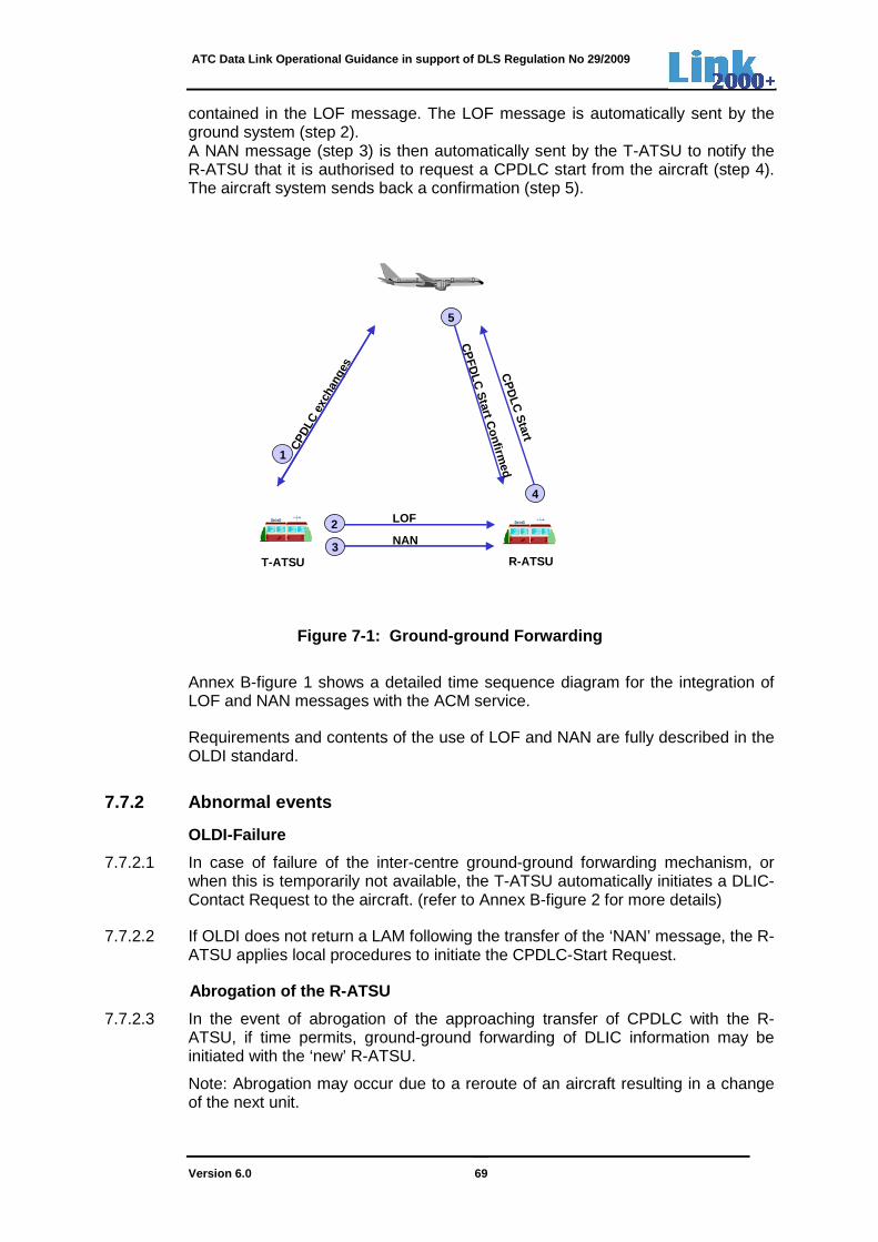
ATC Data Link Operational Guidance in support of DLS Regulation No 29/2009
Version 6.0 69
contained in the LOF message. The LOF message is automatically sent by the ground system (step 2). A NAN message (step 3) is then automatically sent by the T-ATSU to notify the R-ATSU that it is authorised to request a CPDLC start from the aircraft (step 4). The aircraft system sends back a confirmation (step 5).
Figure 7-1: Ground-ground Forwarding
Annex B-figure 1 shows a detailed time sequence diagram for the integration of LOF and NAN messages with the ACM service.
Requirements and contents of the use of LOF and NAN are fully described in the OLDI standard.
7.7.2 Abnormal events
OLDI-Failure
7.7.2.1 In case of failure of the inter-centre ground-ground forwarding mechanism, or when this is temporarily not available, the T-ATSU automatically initiates a DLIC-Contact Request to the aircraft. (refer to Annex B-figure 2 for more details)
7.7.2.2 If OLDI does not return a LAM following the transfer of the ‘NAN’ message, the R-ATSU applies local procedures to initiate the CPDLC-Start Request.
Abrogation of the R-ATSU
7.7.2.3 In the event of abrogation of the approaching transfer of CPDLC with the R-ATSU, if time permits, ground-ground forwarding of DLIC information may be initiated with the ‘new’ R-ATSU.
Note: Abrogation may occur due to a reroute of an aircraft resulting in a change of the next unit.
CPD
LC e
xcha
nges
1
5
CP
DLC
Start
4
CP
FDLC
Start C
onfirmed
T-ATSU R-ATSU
2
3
LOF
NAN
ATC Data Link Operational Guidance in support of DLS Regulation No 29/2009
Version 6.0 70
Notification and ground-ground forwarding of DLIC information to the ‘new’ R-ATSU is achieved as follows:
1. The T-ATSU sends the ‘MAC’ message to the abrogated R-ATSU.
Note: An OLDI message for the abrogation of co-ordination (MAC) is sent by the T-ATSU to indicate to the R-ATSU that the co-ordination or notification previously effected for a flight is being abrogated. The ‘MAC’ message already exists as it is also used in voice environment.
2. The T-ATSU sends a LOF message to the ‘new’ CPDLC-equipped R-ATSU.
3. T-ATSU sends a new NDA message to the aircraft.
Note: The new NDA message, containing the ICAO facility designation of the ‘new’ R-ATSU overwrites the NDA message, sent before, containing the ICAO facility designation of the abrogated T-ATSU.
4. The T-ATSU sends a NAN message to the ‘new’ R-ATSU.
5. The ‘new’ R-ATSU automatically sends a CPDLC start request to the aircraft, based on local constraints.
6. The aircraft confirms the CPDLC start request to the ‘new’ R-ATSU.
Note: The abrogated R-ATSU has not enabled CPDLC for the aircraft concerned, because this ATSU has not received a CDA message from the aircraft and thus has not fulfilled local CPDLC eligibility criteria.
Figure 7-2 presents a diagram illustrating the OLDI and air-ground data link messages exchanged in the event of an abrogated R-ATSU. Numbers shown in the diagram reflect the steps shown above.
If time is not sufficient to execute the above steps, the T-ATSU should terminate the CPDLC connection to allow the aircraft to initiate a logon-request to the ‘new’ R-ATSU.

ATC Data Link Operational Guidance in support of DLS Regulation No 29/2009
Version 6.0 71
Figure 7-2: Abrogated R-ATSU
7.8 Recording
7.8.1 When CPDLC is used for the provision of air traffic control service, the following messages are recorded at the points where data is entering or leaving the ATSU on that air-ground communication channel:
• Logon messages
• CPDLC messages
• Ground-ground data link messages
The recording and replay of the status of the CWP (data representation, display settings and voice synchronisation) is strongly recommended. This is for the purpose of accident/incident investigation and search and rescue.
Archived recordings should be retained for a minimum period of 30 days. More details can be found in EUROCAE document ED-111 [7].
ND
A
6
CP
DLC
Start
5
CP
FD
LC
Start C
onfirm
ed
T-ATSU
Abrogated R-ATSU
3NAN
‘New’R-ATSU
1
2LOF
MAC
4
ATC Data Link Operational Guidance in support of DLS Regulation No 29/2009
Version 6.0 72
8. HUMAN FACTORS GUIDELINES FOR CPDLC
8.1 Consideration of Human Factors
CPDLC differs in some important characteristics from air/ground voice communication and, therefore, will change parts of the controller task. The aim of this chapter is to provide an overview of those characteristics of CPDLC that have an impact on the controller task and that change the mental demands required to carry out the task.
Two classes of changes are identified: CPDLC can either make the controller task easier – these changes are referred to as Human Factors benefits – or it can make the controller task more demanding – these changes are referred to as Human Factors issues. For all identified Human Factors issues, recommendations will be made on how to prevent or at least substantially reduce unwanted effects of CPDLC. Recommendations refer to system and HMI design, operational procedures and training.
Note that this approach is fully in line with ICAO: according to ICAO, it is necessary to resolve Human Factors Issues related to pilot and air traffic controllers before the implementation of a data link based system can take place (ICAO Doc. 9694, I-3-7). As this guidance document is aimed at the ATC community, issues and potential resolutions are limited to those relevant for the air traffic controller.
In the following, HF benefits and HF issues related to the usage of CPDLC are summarized. The identification of HF benefits and issues is based on ICAO documentation (in particular, Doc 9694, 9758, and 4444), HF literature reviews (e.g. Goteman, 2007, Helleberg & Wickens, 2003; Navarro & Sikorski, 1999), EUROCONTROL simulation reports as well as feedback from the operational use of CPDLC.
The Human Factors considerations summarized in this chapter refer to the usage of CPDLC in general; considerations related to a specific data link service (DLIC, ACM, ACL, AMC) is included in the chapters on the respective service.
8.2 Human Factors benefits associated with the use of CPDLC
HF benefits refer to aspects of the controller task that become easier with the introduction of CPDLC. ‘Easier’ means that the task poses fewer demands on cognitive processes such as attention, perception, interpretation, memory, decision making, as well as response selection and execution. In the following, the main HF benefits related to the implementation of CPDLC are described.
8.2.1 Reduction of voice channel congestion
By reducing voice channel congestion, the number of communications that are missed due to blockage of the frequency is decreased. Furthermore, communication delays caused by the unavailability of the voice channel are reduced. For the controller, this means that the need for re-transmissions decreases, which includes both re-transmissions of the ATC call as well as requesting a station to re-transmit its calls. Also, the timing of a communication is

ATC Data Link Operational Guidance in support of DLS Regulation No 29/2009
Version 6.0 73
to a larger extent under the control of ATC, rather being dictated by external constraints.
8.2.2 Decrease in communication errors
Errors in voice communication can be caused by miscomprehension of messages (i.e. failure to understand the message), working memory restrictions (i.e. failure to retain the message in memory), vulnerabilities of the read-back process (i.e. read-back and hear-back errors), and message confusion (i.e. erroneous receipt of messages). These errors are less likely in data link communication as the content of the dialogue is available in a more permanent written format. The more permanent nature of the dialogue makes it less prone to misperception or miscomprehension on the one hand and forgetting or mis-remembering on the other. Another error relates to the situation in which the controller intends to give a certain instruction, but erroneously issues a different instruction (i.e. ‘slip of the tongue’). Although a similar error is possible with data link (i.e. a wrong selection of a clearance for uplink), there is a higher change that the controller will detect it. The reason is that, with CPDLC, the new clearance will be displayed at the controller working position.
8.2.3 Reduction in ATC communication workload
For the controller, the main ‘task savings’ associated to the reduction in R/T communication are related to the fact that monitoring of the pilot read-back is no longer required with CPDLC. This amounts to a reduced demand on controller working memory. Furthermore, depending on the actual implementation of data link services, some communication tasks (such as transferring an aircraft to the next sector) require less mental and physical actions than carrying out the task by R/T (and having to update the ATC system when the voice transfer is made).
8.2.4 Increased flexibility in handling ATC communi cation tasks
Compared with data link messages, R/T communication messages are generally perceived as more urgent as they require an immediate response from the recipient (at least a “stand-by” response). For this reason, R/T messages are more likely to disrupt the controller in other ongoing activities, which can result in a failure to complete these activities. Data link messages, in contrast, allow for a higher level of flexibility. This flexibility relates to (a) the timing of the response (i.e. the delay between incoming message and the response) and (b) the prioritization of incoming messages (i.e. the order in which incoming messages are handled).
8.2.5 Possibility of a flexible task allocation wit hin the controller team
CPDLC offers opportunities for a task allocation between Planning Controller and Tactical Controller, in which the Planning Controller – in addition to the Tactical Controller – carries out data link communication with the flight crew of an aircraft with CPDLC capability. In this way, the Planner may be able to support the Tactical Controller to a larger extent than in the current (i.e. R/T based) task allocation, in which only the Tactical Controller communicates with the flight crew. There are, however, a number of caveats that need to be considered if a flexible allocation of communication tasks within the controller team is chosen (see Section 8.3.6).

ATC Data Link Operational Guidance in support of DLS Regulation No 29/2009
Version 6.0 74
8.3 Human Factors issues associated with the use of CPDLC
HF issues refer to aspects of the controller task that become more difficult or more prone to error with the introduction of CPDLC. ‘More difficult’ means that the task poses increased demands on cognitive processes such as attention, perception, interpretation, memory, decision making, as well as response selection and execution. Furthermore, the implementation of CPDLC may result in new controller tasks or task components. In the following, the main HF Issues related to the implementation of CPDLC are described and recommendations on how to resolve the issues are made.
8.3.1 Communication delays in CPDLC
Completing an air-ground message exchange by data link takes considerably longer than exchanging information between air and ground by R/T. ICAO refers to studies showing that “total transaction time (i.e. the entire time span when a controller would be concerned with a given communication) was twice as long for data link as for voice”. Exact numbers, however, are difficult to derive. The reason is that transaction times are composed of a number of different delays, including technical delays for transmitting the message, and operator-based delays, such as latencies in detecting, processing and composing a data link message (pertaining to both the air traffic controller and the pilot). In any case, communication speed has been identified as one of the main issues in the implementation of CPDLC.
Recommendations:
8.3.1.1 Operational procedure design and training should include the fact that CPDLC shall only be used in the context of routine CPDLC exchanges. Voice communications are the prevailing option for transmitting ‘immediate action’ messages.
8.3.1.2 Controllers should be trained on how to assess a routine dialogue.
8.3.2 Detection and processing of visual informatio n
Visual information (used in CPDLC exchanges) shows qualitatively different properties than auditory information (used in voice communication). These differences can have an impact on human information detection and processing. For instance, an advantage of visual information is that it is less transient than auditory information; thereby reducing working memory demands and the potential for error (see Section 8.2.2). On the other hand, visual information is more difficult to detect than auditory information. This means that (a) the detection latency for visual information tends to be longer, and (b) there is a higher risk of not detecting visual information (particularly, if the information is not presented within the operator’s focus of attention). Moreover, if visual symbols are used to convey CPDLC related information (e.g. ‘CPDLC enabled’ status or ‘log-on‘ status), there is a risk of misinterpretation.
Recommendation:
8.3.2.1 The HMI should support a timely detection of an incoming message. In order to do so, indications of incoming messages should be presented in the controller’s

ATC Data Link Operational Guidance in support of DLS Regulation No 29/2009
Version 6.0 75
focus of attention (i.e. on the traffic situation display). Auditory alerts, in contrast, may not be recommendable.
8.3.2.2 Controllers should be trained on all visual symbols used for conveying CPDLC related information.
8.3.3 Competition for visual resources
The task of an air traffic controller is already based on the detection, interpretation and integration of large amounts of visually presented information. By shifting formerly auditory information (that is, voice) to the visual modality, there may be a risk to overload the visual channel. Two different aspects have to be considered: First, it has to be ensured that the perception and composition of data link messages do not distract controller’s visual attention unduly from any safety-critical displays (above all, the traffic situation display). Second, if DL information is presented on the traffic situation display, it needs to be ensured that it does not obscure any safety-critical information.
Recommendations:
8.3.3.1 To avoid diverting controllers’ visual attention from the traffic display, key information related to a CPDLC dialogue (e.g. the message notification and the status of a data link dialogue) should be presented on the traffic display, preferably in (or in close proximity to) the aircraft label (data block).
8.3.3.2 To avoid clutter of the traffic display, additional message information (e.g. the full text of the message, the history of sent and received messages) should be presented on a separate screen or window.
8.3.4 Composition of CPDLC messages
Composing a data link message takes more time and effort than using voice for air-ground communication. The extent of the additional effort will depend on the specific interface chosen. For this reason, the interfaces need to be designed in such a way that they are efficient, easy to operate and provide a rapid message input mechanism. For the controller working position, interface solutions have been proposed that do not require any additional input for composing a data link clearance over those needed to enter a clearance into the ATC system in an electronic environment (cf. EUROCONTROL-HMI Catalogue [ref 4]).
Recommendations:
8.3.4.1 The number of inputs needed to compose or respond to a message should be minimized. This includes an easy access to messages (in case pre-formatted messages are used) or message parameters (e.g., use of defaults for data link clearances).
8.3.4.2 In an electronic environment, possibilities should be investigated to update the system automatically (i.e., modify the aircraft trajectory) once a CPDLC clearance has been accepted by the pilot.
8.3.5 Controller team situation awareness
The majority of airspace in the European area is controlled by sector teams (consisting of a Planning Controller and a Tactical Controller). With voice

ATC Data Link Operational Guidance in support of DLS Regulation No 29/2009
Version 6.0 76
communication, both controllers are able to hear all exchanges between air and ground. With CPDLC, in contrast, the Planning Controller may not be aware of messages sent between the Tactical Controller and the flight crew. This may lead to a decrease in team situation awareness (i.e., the shared mental picture of Planning and Tactical Controller). The decrease in team situation awareness may also be relevant for on-the-job training (OJT), where it is of paramount importance that the instructor can follow the instructions issued by the trainee.
Recommendations:
8.3.5.1 In case of sector team operations, the Planning Controller should be provided with the same CPDLC interface as the Tactical Controller. In this way, the Planning Controller is informed on the status of data link dialogues as well as the outcome of the dialogues (in terms of changes to the flight profile).
8.3.5.2 Special care should be taken that in OJT situations the instructor is at all times aware of the status and content of all data-link dialogues carried out by the trainee. In addition to providing the same HMI (see Recommendation 8.3.5.1), shared situation awareness between trainee and instructor can also be supported by the requirement to verbalize all CPDLC instructions before sending them.
8.3.6 Possibility of flexible task allocation in th e controller team
With CPDLC, there is a possibility to modify the task allocation within the controller team in such a way that the Planning Controller may support the Tactical Controller in carrying out data link communication with the flight crew. If such a task allocation is proposed, though, the following issues need to be considered:
a) There is an increased need for intra-team communication to maintain clarity about which controller (Planning vs. Tactical Controller) is responsible for sending what type of messages to a particular aircraft.
b) In case of reversion to voice (e.g. because of data link failure or a dialogue being timed out), the Tactical Controller will have to carry out the communication, regardless of whether he was the one to originally send the data link message or not.
c) A task division according to which both controllers may send messages to the aircraft may result in an evolution of the Planning Controller’s role towards a second Tactical Controller. This means that the Planning Controller will work on the same time scale as the Tactical Controller and has fewer resources to pre-plan traffic before it enters the sector.
Recommendations:
8.3.6.1 Procedure design and training should include a clear division of tasks between the Planning Controller and the Tactical Controller related to CPDLC communication. In particular, it needs to be described which controller role is responsible for sending which type of data link messages. In the transition phase, it may be advisable to maintain the existing allocation of tasks between the Planning Controller and the Tactical Controller.
8.3.6.3 In case the Planning Controller can send data link messages, specific procedures for reversion to voice need to be designed and included in the training.

ATC Data Link Operational Guidance in support of DLS Regulation No 29/2009
Version 6.0 77
8.3.6.4 The impact of the chosen task allocation (with respect to sending data link messages) on other aspects of the Planning Controller’s role needs to be carefully considered.
8.3.6.5 Potential benefits and issues related to the allocation of CPDLC to the Planning Controller will depend on the type of dialogue. For instance, dialogues related to the transfer of an aircraft (ACM) or requesting information from the pilot may be more easily allocated to the Planning Controller than dialogues related to issuing an instruction (ACL).
8.3.7 Sequential vs. parallel dialogues
With the introduction of CPDLC, the nature of air-ground dialogues changes. Because of longer delays in the reception of a pilot response, the controller may have several open data link dialogues at the same time (i.e. parallel dialogues). This is different from a standard voice dialogue in which a controller would usually close a communication with one aircraft, before initiating a communication with another one (i.e. sequential dialogues). The fact that several data link dialogues can be open in parallel amounts to increased memory demands for the controller: The controller needs to remember which dialogues are open and, thus, which instructions are not yet implemented.
Recommendations:
8.3.7.1 The HMI should provide a clear indication of open and recently closed dialogues (e.g. in a message history window).
8.3.7.2 Expiration timers for dialogues should be defined in such a way that a balance is found between giving the flight crew a chance to respond to the message and to avoid keeping the dialogue open for too long.
Note: See section 5.6 for timer settings, specified for the data link services.
8.3.8 Rigidity of data link communication
There is a higher degree of rigidity in the exchange of data link messages than in the exchange of voice messages. This is due to the fact that data link dialogues are often restricted to a specific message set, because the use of free text is not recommended. As a consequence, data link dialogues are less suitable for complex dialogues and negotiations that may require explanations.
Recommendation:
8.3.8.1 Procedure design and training should reinforce that voice is the preferred option for complex dialogues (e.g. concatenated messages) or negotiations.
Note: With the current limitations of the message set, defined in the EUROCONTROL Specification, this recommendation may not be relevant.
Guidelines for concatenated messages are provided in Chapter 10 of this document.
8.3.9 Choice between voice and data link for a dial ogue
Because of the higher degree of rigidity and the delays involved in CPDLC, CPDLC does not substitute but supplements voice communication (in the context

ATC Data Link Operational Guidance in support of DLS Regulation No 29/2009
Version 6.0 78
of the envisaged environment, voice is the primary means of communication). It is recommended to use voice (a) for messages that are non-routine and require immediate action, and (b) for complex dialogues or negotiations (Doc. 9758, 5-1). This means that before initiating an interaction, the controller needs to make a decision on whether or not CPDLC is the appropriate means for communication with the flight crew.
Recommendations:
8.3.9.1 Procedure design and training should include the fact that CPDLC shall only be used in the context of routine communications.
8.3.9.2 Controllers should be trained on how to assess routine exchanges in the context of CPDLC.
8.3.9.3 Procedure design and training should reinforce that voice is to be used for complex dialogues and negotiations.
8.3.10 Reversion to voice communication
After a CPDLC dialogue has been initiated with an aircraft, it may become necessary to revert to voice. There are various reasons for a reversion to voice: CPDLC failure, a timed-out dialogue, the need for corrective actions or clarifications to a CPDLC message, and changes in the time-criticality of an instruction (for a more detailed description see Chapter 6.8). Thus, there is a new decision to be made by the controller as to when a specific situation warrants the reversion form CPDLC to R/T communication. Once the decision is made, the controller needs to apply the procedures and phraseology related to a reversion to voice. The use of adequate procedures and a clear phraseology play an important role in minimizing any ambiguity as to which message (data link or voice) takes precedence.
Recommendations:
8.3.10.1 Procedure design and training should specify the situations that require a reversion form CPDLC to voice.
8.3.10.2 Procedures should clearly describe the actions required to revert from CPDLC to voice.
8.3.10.3 Controllers should be trained on the phraseology related to the reversion from a CPDLC dialogue to voice communication.
8.3.10.4 The HMI should allow the controller to close a data link dialogue if reversion to voice is needed.
8.3.11 Mix of aircraft with and without CPDLC capab ility
It can be assumed that, for a considerable time period, the air traffic controller has to work with a mixture of aircraft with and without CPDLC capability. This means that controllers will have to switch between voice and data link communication, even if all communication with CPDLC capable aircraft was done by data link. The shift between different modalities is potentially associated with ‘cognitive costs’ in terms of longer latencies and increased error potential in comparison to a situation in which controllers only work within one modality.
ATC Data Link Operational Guidance in support of DLS Regulation No 29/2009
Version 6.0 79
Adverse effects of operating in a mixed environment can be reduced by rendering it perceptually salient which communication means is available for a particular aircraft.
Recommendation:
8.3.11.1 The HMI should provide a clear differentiation of data-link equipped and unequipped aircraft. This differentiation should be displayed at all times and should be associated to the radar label or position symbol.
8.3.12 Availability of CPDLC
Although an aircraft can have CPDLC capability, it may not be possible for the controller to communicate with it via data link. A potential reason is that, although the current ATSU has received the log-on information from the aircraft, it may have not yet established a CPDLC connection. Once the CPDLC connection has been established, the current ATSU only enables the use of CPDLC, after the controller has assumed the flight.
From the perspective of the controller, this means that the CPDLC connection status (established or enabled) has to be taken into account when deciding whether or not to use CPDLC for communication with an aircraft. To support this decision, the CPLC connection status for an aircraft should be indicated.
Recommendations:
8.3.12.1 The HMI should provide a clear distinctive indication of the ‘log-on’ status and ‘CPDLC connection’ status of an aircraft to the controller.
8.3.12.2 The HMI should provide a clear indication to the controller when the ‘CPDLC connection’ status is switched from the ‘established’ status to the ‘enabled’ status.

ATC Data Link Operational Guidance in support of DLS Regulation No 29/2009
Version 6.0 80
9. TRAINING GUIDELINES FOR THE USE OF CPDLC
These guidelines may be used to assist in the development of a training programme for CPDLC for qualified controllers at ACCs. They are based on the training need identified so far in CPDLC implementation and are targeted at transition training. They do not consider the training guidelines for ab-initio controllers.
9.1 Data link services and CPDLC messages
9.1.1 Controllers should be able to name the data link services implemented in their operational environment.
9.1.2 Controllers should be able to list the CPDLC messages being used in their operational environment.
Knowledge of the message set should include
• All available uplinks; • All available downlinks, and; • All available responses - both pilot and controller initiated.
9.2 Use of CPDLC
9.2.1 Controllers should be able to clearly explain the difference between data link log on, CPDLC connection and CPDLC enabled.
Confusion sometimes exists as to the different status of an aircraft during the initiation of CPDLC. For example, there is an operational difference to a controller between an aircraft, which is simply logged-on, and one with whom CPDLC is enabled.
9.2.2 Controllers should be able to clearly define the context in which CPDLC will be used.
It is not the intention to replace voice communications with data link communications. Voice is the primary communication method used in continental Europe today, and it is foreseen to remain that way. CPDLC will be used as a supplementary means of communication only.
9.2.3 Controllers should be able to clearly decide when the use of CPDLC is possible.
CPDLC should only be used in a routine ATC situation, current CPDLC performance does not allow for non-routine use. When a controller issues a clearance using CPDLC he must understand that he is giving away a specific amount of time [operational response time plus technical delay] for the instruction to be complied with. In this context it can be seen that it is the ATC situation that determines whether a CPDLC message should be used or not.
9.2.4 When using CPDLC, controllers should be able to define when they would revert to voice communication.
CPDLC is a silent medium. Given its fixed messages structure it does not have the ability to convey doubt and misunderstanding in the same way that voice intonation can. Therefore, it must be emphasised to controllers that if any doubt exists as to the validity

ATC Data Link Operational Guidance in support of DLS Regulation No 29/2009
Version 6.0 81
of an exchange, or if they are in any way unsure as to the safe completion of a data link exchange in time, they must always revert to voice to resolve the situation.
9.2.5 Controllers should be able to specify the maximum possible CPDLC dialogue time permitted in order to be aware of when they might have to revert to voice communications when issuing clearances and instructions.
When a controller issues an instruction or clearance by voice he expects an immediate readback or acknowledgement. Using CPDLC the controller should appreciate that the response will take much longer.
9.2.6 Controllers should be able to explain how CPDLC is terminated.
Currently, the use of CPDLC is not mandatory. As operational circumstances dictate, a controller and flight crew are free to use CPDLC or not. Controllers should be aware of this possibility, and the associated procedures.
9.2.7 Controllers should be able to state the R/T phraseology associated with CPDLC operations
9.2.8 Where controllers within a sector team are both given responsibilities for the communication task each controller should be able to clearly differentiate which task has been allocated to each member of the team.
Particular attention should be given to clearly defining the task allocation and the need to identify potential error modes and their consequences.
9.3 Timers and system errors
9.3.1 Controllers should be able to list and explain the difference between the various timers used in CPDLC and described in 5.6.
The parameters for these timers will effect the use of CPDLC and the timing and type of ‘error’ messages being produced. Controllers should be informed of these timers and their significance.
9.3.2 Controllers should be able to differentiate between error messages generated by the system and how to respond to them.
When any of the timers mentioned above expire, error messages are generated. Controllers must understand what these errors signify in terms of message assurance and the impact on general CPDLC operation.
Controllers should also be briefed on the appropriate response in the event of an error being generated by the system.
9.4 Abnormal events
9.4.1 Controllers should be able to state the procedures in the event of aircraft radio communication failure.
Controllers shall respect existing ICAO radio communication failure procedures under these circumstances.
9.4.2 Controllers should be able to state and practice the procedures in the event of a CPDLC communications failure.
ATC Data Link Operational Guidance in support of DLS Regulation No 29/2009
Version 6.0 82
Controllers should be trained in how to deal with a failure of CPDLC scheduled withdrawal or unscheduled failure.
Training for this should include the standard phraseology to use in the event of CPDLC being unusable. It should also include training in the return of the system to use, including understanding the fact that messages might still be present in the system.
9.5 Human machine interface
9.5.1 Controllers should be able to practice and demonstrate how to initiate and send the CPDLC messages implemented in their operational environment.
9.5.2 Controllers should be able to practice and demonstrate how to handle down link requests from flight crew and how to respond using CPDLC messages implemented in their operational environment.
ATC Data Link Operational Guidance in support of DLS Regulation No 29/2009
Version 6.0 83
10. GUIDELINES FOR CONCATENATED MESSAGES AND CLOSURE
10.1 Introduction
A concatenated CPDLC message is a message containing more than one CPDLC message element. ICAO PANS-ATM [11] and the EUROCAE-Document ED-110B [6] do not impose strict rules with respect to concatenated CPDLC messages. Both documents allow a maximum of 5 message elements in a concatenated message. This could give the possibility of creating concatenated messages not always having an operational meaning.
This section provides more guidance to ground implementers and HMI designers on the composition of concatenated messages and their respective closure responses. It also provides recommendations to controllers on their operational use and informs controllers on the possible aircraft implementations, when responding to specific flight crew initiated concatenated messages.
10.2 CPDLC message attributes
As stated in 4.2, each CPDLC message element has Response, Urgency and Alert attributes. Ground- and aircraft systems, compliant to the EUROCONTROL specification, are required only to use and adhere to the ‘Response’ attribute. The use of the other two attributes (Urgency and Alert) is a local implementation option.
A full list of ‘Response’, ‘Urgency’ and ‘Alert’ attributes is presented in Annex C.
In accordance with ICAO Annex 10 [10] – “When a message contains multiple message elements, the highest precedence message element attribute for each attribute type associated with any element in the message shall be the message attribute for each attribute type for the entire message.”
(e.g. the concatenation of UM20 (W/U) with UM222 (R) - CLIMB TO [level] NO SPEED RESTRICTION - will have the response attribute of the UM20 - W/U.)
10.3 Controller-initiated concatenation of message elements
10.3.1 Operational guidance for the use of concaten ated CPDLC messages
10.3.1.1 Clearances
In accordance with GOLD Ed 2.0 [15], the controller should only combine clearance or instruction message elements that are dependent on each other into a single uplink message as the flight crew can only provide a single unambiguous response.
Note 1.— A dependent clearance is a message consisting of more than one clearance element, where the flight crew is required to comply with each of the elements. A rejection of any of the elements, either singly or in combination, renders the entire clearance invalid.

ATC Data Link Operational Guidance in support of DLS Regulation No 29/2009
Version 6.0 84
Note 2.— Sending the elements as individual messages may compromise safety or separation if the flight crew accepts the first uplink of a dependent clearance, complies with the instruction, and then responds UNABLE to the next message when received.
Note 3.— The flight crew will respond to the multi-element uplink message with either WILCO or UNABLE, which applies to the entire message per paragraph 6.5.6.2.
Note 4.— The controller should not send two independent clearances in a single message because the flight crew cannot individually respond to each clearance, if necessary (e.g. WILCO one clearance and UNABLE the other).
10.3.1.2 Number of concatenated message elements For ground systems compliant to the EUROCONTROL Specification [4], an uplink concatenated message should contain maximum 2 clearances, instructions or report/information requests.
It is strongly recommended not to use message element UM165 – [THEN] for concatenation of messages as it does not reflect sufficiently clear the intended operational use, and it may lead to ambiguities.
Recognising that the implementation of concatenated messages is dependent on the airspace operational particularities, it is expected that each ground system, compliant to the EUROCONTROL specification, will use its own subset of concatenated messages, selected from those given in the tables below.
Note: Interoperability requirements for concatenated messages are specified in ED-110B [6].
10.3.2 Concatenation of message elements with respo nse attribute other than Y
The six tables below present the list of uplink concatenated messages for systems compliant to the EUROCONTROL Specification. Within each table, one instruction from the left table column can be concatenated with one of the instructions from the right column, except for the table in 10.3.2.2, where instructions to Climb or Descend can be concatenated with both a maximum and minimum ‘Climb or Descend Rate’ instruction.
Note 1: It is expected that the message elements order in a concatenated message is preserved when the concatenated message is displayed to the pilots.
Note 2: Message elements in bold are mandatory for systems, compliant to the EUROCONTROL Specification.
Note 3: In accordance with 10.2 above, the response attribute of the concatenated message resulted from the combination of such message elements is W/U.
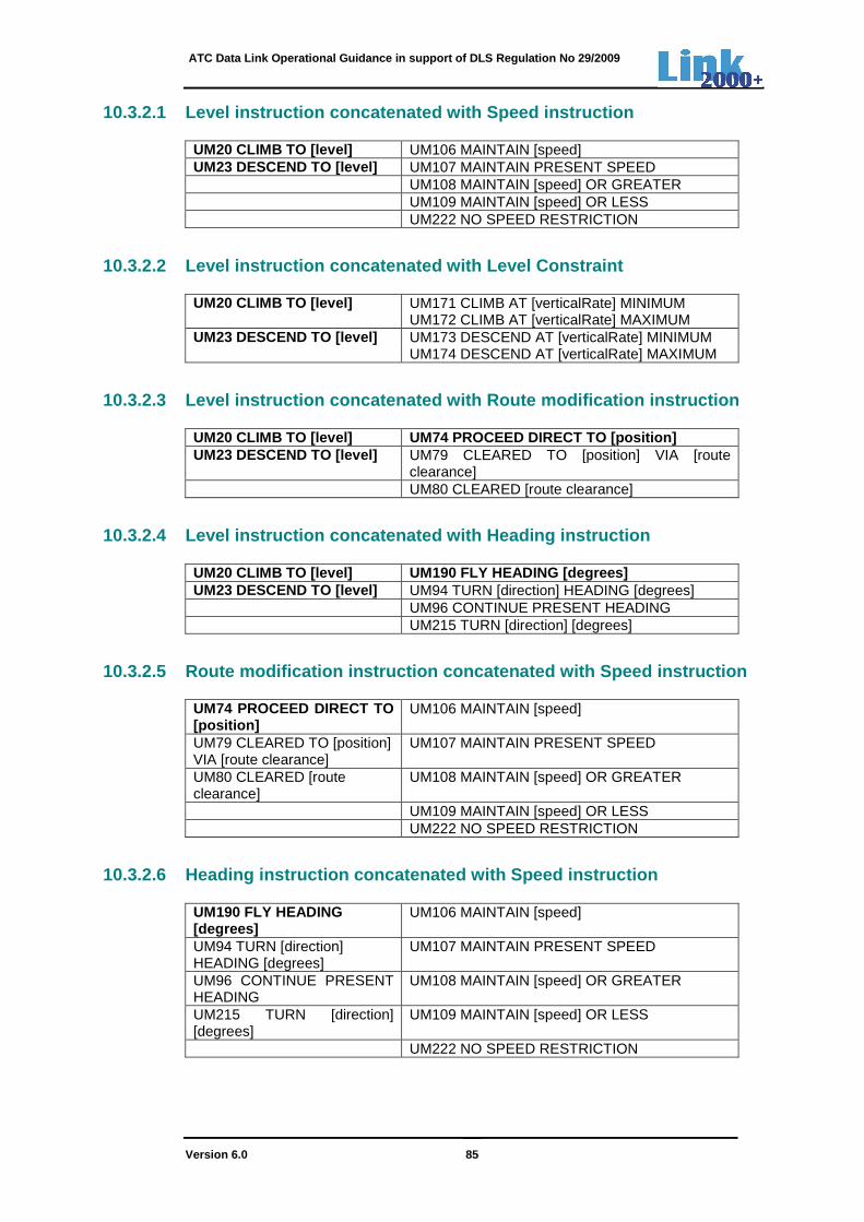
ATC Data Link Operational Guidance in support of DLS Regulation No 29/2009
Version 6.0 85
10.3.2.1 Level instruction concatenated with Speed instruction
UM20 CLIMB TO [level] UM106 MAINTAIN [speed] UM23 DESCEND TO [level] UM107 MAINTAIN PRESENT SPEED UM108 MAINTAIN [speed] OR GREATER UM109 MAINTAIN [speed] OR LESS UM222 NO SPEED RESTRICTION
10.3.2.2 Level instruction concatenated with Level Constraint
UM20 CLIMB TO [level] UM171 CLIMB AT [verticalRate] MINIMUM UM172 CLIMB AT [verticalRate] MAXIMUM UM23 DESCEND TO [level] UM173 DESCEND AT [verticalRate] MINIMUM UM174 DESCEND AT [verticalRate] MAXIMUM
10.3.2.3 Level instruction concatenated with Route modification instruction
UM20 CLIMB TO [level] UM74 PROCEED DIRECT TO [posit ion] UM23 DESCEND TO [level] UM79 CLEARED TO [position] VIA [route
clearance] UM80 CLEARED [route clearance]
10.3.2.4 Level instruction concatenated with Headin g instruction
UM20 CLIMB TO [level] UM190 FLY HEADING [degrees] UM23 DESCEND TO [level] UM94 TURN [direction] HEADING [degrees] UM96 CONTINUE PRESENT HEADING UM215 TURN [direction] [degrees]
10.3.2.5 Route modification instruction concatenate d with Speed instruction
UM74 PROCEED DIRECT TO [position]
UM106 MAINTAIN [speed]
UM79 CLEARED TO [position] VIA [route clearance]
UM107 MAINTAIN PRESENT SPEED
UM80 CLEARED [route clearance]
UM108 MAINTAIN [speed] OR GREATER
UM109 MAINTAIN [speed] OR LESS UM222 NO SPEED RESTRICTION
10.3.2.6 Heading instruction concatenated with Spee d instruction
UM190 FLY HEADING [degrees]
UM106 MAINTAIN [speed]
UM94 TURN [direction] HEADING [degrees]
UM107 MAINTAIN PRESENT SPEED
UM96 CONTINUE PRESENT HEADING
UM108 MAINTAIN [speed] OR GREATER
UM215 TURN [direction] [degrees]
UM109 MAINTAIN [speed] OR LESS
UM222 NO SPEED RESTRICTION
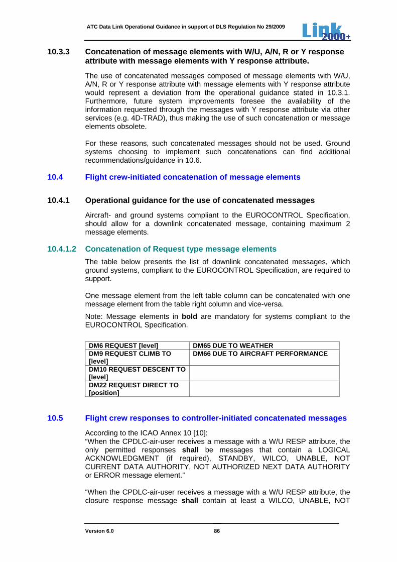
ATC Data Link Operational Guidance in support of DLS Regulation No 29/2009
Version 6.0 86
10.3.3 Concatenation of message elements with W/U, A/N, R or Y response attribute with message elements with Y response att ribute.
The use of concatenated messages composed of message elements with W/U, A/N, R or Y response attribute with message elements with Y response attribute would represent a deviation from the operational guidance stated in 10.3.1. Furthermore, future system improvements foresee the availability of the information requested through the messages with Y response attribute via other services (e.g. 4D-TRAD), thus making the use of such concatenation or message elements obsolete. For these reasons, such concatenated messages should not be used. Ground systems choosing to implement such concatenations can find additional recommendations/guidance in 10.6.
10.4 Flight crew-initiated concatenation of message elements
10.4.1 Operational guidance for the use of concaten ated messages
Aircraft- and ground systems compliant to the EUROCONTROL Specification, should allow for a downlink concatenated message, containing maximum 2 message elements.
10.4.1.2 Concatenation of Request type message elem ents
The table below presents the list of downlink concatenated messages, which ground systems, compliant to the EUROCONTROL Specification, are required to support. One message element from the left table column can be concatenated with one message element from the table right column and vice-versa.
Note: Message elements in bold are mandatory for systems compliant to the EUROCONTROL Specification.
DM6 REQUEST [level] DM65 DUE TO WEATHER DM9 REQUEST CLIMB TO [level]
DM66 DUE TO AIRCRAFT PERFORMANCE
DM10 REQUEST DESCENT TO [level]
DM22 REQUEST DIRECT TO [position]
10.5 Flight crew responses to controller-initiated concatenated messages
According to the ICAO Annex 10 [10]: “When the CPDLC-air-user receives a message with a W/U RESP attribute, the only permitted responses shall be messages that contain a LOGICAL ACKNOWLEDGMENT (if required), STANDBY, WILCO, UNABLE, NOT CURRENT DATA AUTHORITY, NOT AUTHORIZED NEXT DATA AUTHORITY or ERROR message element.” “When the CPDLC-air-user receives a message with a W/U RESP attribute, the closure response message shall contain at least a WILCO, UNABLE, NOT

ATC Data Link Operational Guidance in support of DLS Regulation No 29/2009
Version 6.0 87
CURRENT DATA AUTHORITY, NOT AUTHORIZED NEXT DATA AUTHORITY or ERROR message element.” “A CPDLC-user shall only be permitted to respond to a received message in its entirety.”
10.5.1 Responding to concatenation of message eleme nts with response attribute other than Y
This paragraph indicates how the aircraft should respond to messages given in 10.3.2 above.
The permitted response will be messages containing one of the following message elements: LOGICAL ACKNOWLEDGMENT (if required), STANDBY, WILCO, UNABLE, NOT CURRENT DATA AUTHORITY, NOT AUTHORIZED NEXT DATA AUTHORITY or ERROR message element.
The closure response message will be a message containing one of the following message elements: WILCO, UNABLE, NOT CURRENT DATA AUTHORITY, NOT AUTHORIZED NEXT DATA AUTHORITY or ERROR message element.
The WILCO or UNABLE response messages will operationally apply to the entire uplink concatenated message – see 6.5.6.1 and 6.5.6.2.
As responses to a ground initiated dialogue, ground systems compliant to the EUROCONTROL Specification are required to also support the following downlink concatenated messages:
DM1 UNABLE DM65 DUE TO WEATHER DM82 WE CANNOT ACCEPT [level] 1)
DM66 DUE TO AIRCRAFT PERFORMANCE
1) Support required only if UM148 is supported
Note 1: Each message element from the left table column can be concatenated with each message element from the table right column.
Note 2: Message elements in bold are mandatory for systems compliant to the EUROCONTROL Specification.
10.6 Guidance for ground- and aircraft systems supp orting concatenation of message elements W/U with Y response attributes
10.6.1 Recommended concatenation of uplink message elements
As stated in 10.3.3, the use of concatenations of a message element with the ‘W/U’ response attribute and a message element with the ‘Y’ response attribute should be avoided. In case ANSPs wish to use such concatenations, the following uplink concatenated message elements are recommended:
UM20 CLIMB TO [level] UM148 WHEN CAN YOU ACCEPT [level] UM231 STATE PREFERRED LEVEL
UM74 PROCEED DIRECT TO [position]
UM231 STATE PREFERRED LEVEL
UM148 WHEN CAN YOU ACCEPT [level] UM133 REPORT PRESENT LEVEL UM232 STATE-TOP-OF-DESCENT
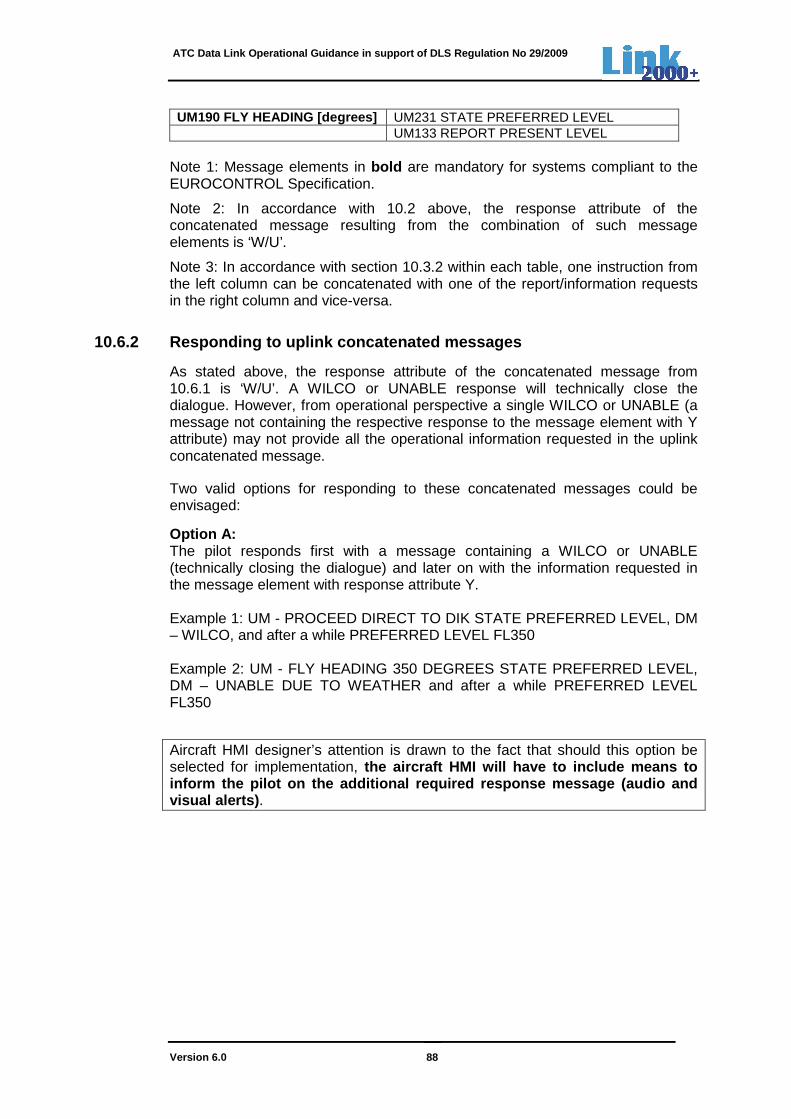
ATC Data Link Operational Guidance in support of DLS Regulation No 29/2009
Version 6.0 88
UM190 FLY HEADING [degrees] UM231 STATE PREFERRED LEVEL UM133 REPORT PRESENT LEVEL
Note 1: Message elements in bold are mandatory for systems compliant to the EUROCONTROL Specification.
Note 2: In accordance with 10.2 above, the response attribute of the concatenated message resulting from the combination of such message elements is ‘W/U’.
Note 3: In accordance with section 10.3.2 within each table, one instruction from the left column can be concatenated with one of the report/information requests in the right column and vice-versa.
10.6.2 Responding to uplink concatenated messages
As stated above, the response attribute of the concatenated message from 10.6.1 is ‘W/U’. A WILCO or UNABLE response will technically close the dialogue. However, from operational perspective a single WILCO or UNABLE (a message not containing the respective response to the message element with Y attribute) may not provide all the operational information requested in the uplink concatenated message.
Two valid options for responding to these concatenated messages could be envisaged:
Option A: The pilot responds first with a message containing a WILCO or UNABLE (technically closing the dialogue) and later on with the information requested in the message element with response attribute Y. Example 1: UM - PROCEED DIRECT TO DIK STATE PREFERRED LEVEL, DM – WILCO, and after a while PREFERRED LEVEL FL350 Example 2: UM - FLY HEADING 350 DEGREES STATE PREFERRED LEVEL, DM – UNABLE DUE TO WEATHER and after a while PREFERRED LEVEL FL350
Aircraft HMI designer’s attention is drawn to the fact that should this option be selected for implementation, the aircraft HMI will have to include means to inform the pilot on the additional required respons e message (audio and visual alerts) .
ATC Data Link Operational Guidance in support of DLS Regulation No 29/2009
Version 6.0 89
Option B: The pilot responds with a concatenated message containing all operational responses required. Example: UM - PROCEED DIRECT TO DIK STATE PREFERRED LEVEL; DM – WILCO PREFERRED LEVEL FL350 or UNABLE PREFERRED LEVEL FL350 Should this option be selected for implementation, the aircraft HMI will not allow the pilot to send the WILCO/UNABLE as single messag e element. The preferred option by the operational experts is B. Option A is not recommended as it would represent a deviation from the cockpit workflow and is error-prone to omissions. It should be emphasized that a concatenated response (WILCO/UNABLE response to the instruction + STANDBY response to the message element with ‘Y’ attribute) is strongly dissuaded from use. A partial STANDBY would be confusing to the controller.
If a STBY has to be answered, it should be sent as a single message element, applying thus to the entire concatenated message. This is then followed by responses to operationally close the concatenated message.
Ground systems implementing concatenation of message elements with W/U response attribute with message elements with Y response attribute, will be able to accept responses from aircraft systems compliant to either option A or B.
ATC Data Link Operational Guidance in support of DLS Regulation No 29/2009
Version 6.0 90
11. NOTIFICATION OF DATA LINK SERVICES
Where data link services are provided, each State will notify airspace users of data link service provisions, service schedule, relevant procedures, and confirmation of compliance with relevant standards by the following means:
– Aeronautical Information Circular (AIC)
– Aeronautical Information Publication (AIP)
– Notification to Airmen (NOTAM)
An AIC is issued as an advanced notice to the AIP.

ATC Data Link Operational Guidance in support of DLS Regulation No 29/2009
Version 6.0 91
ANNEXES AND APPENDIX
ATC Data Link Operational Guidance in support of DLS Regulation No 29/2009
Version 6.0 92
ANNEX A: EUROCONTROL SPECIFICATION - CPDLC MESSAGE SET FOR GROUND SYSTEMS
A.1. SPECIFIC SERVICE REQUIREMENTS
Each of the different CPDLC services have their specific functionality and their set of messages and, where applicable, message elements.
For the services, using the CPDLC application, the tables below list the mandatory and optional set of message elements derived from EUROCAE Document ED-110B [6] and further restricted through the EUROCONTROL Specification [4].
This document fully describes how the services are to be implemented, including error handling.
For services using the CPDLC application:
• "Mandatory" means that all ground systems of participating States must implement the messages and make them available to the controller. In cases where unsupported uplink messages are required from the certification or approval process, the ground system must be capable of emulating such messages without using the controller HMI. Not supported downlink messages have to be properly decoded and responded with error message element UM162 or a UM159 ‘ERROR’ (error information) + free text message element UM183, containing the text ‘ELEMENT COMBINATION REJECTED – USE VOICE’. This rule ensures a minimum level of harmonisation of the provision and use of CPDLC based data link services within the regulated airspace.
• "Optional" means that ground systems are free to decide whether or not to implement and use the messages.
A.1.1 CPDLC based services A.1.1.1 ACM A.1.1.1.1 Functionality
ACM provides automated assistance to the flight crew and current and subsequent controllers in conducting the transfer of ATC communications. ACM encompasses the change of voice channels and, where necessary, the termination and re-establishment of the CPDLC connection.
In ED-110B, ACM is described with two fundamental variants, identified as "Case A" and "Case B". The EUROCONTROL Specification mandates case A.
A.1.1.1.2 Mandatory uplink messages
The Ground system must support the following Uplink ACM message elements:
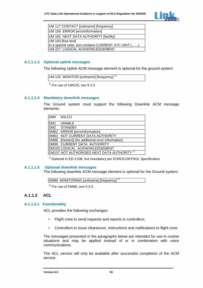
ATC Data Link Operational Guidance in support of DLS Regulation No 29/2009
Version 6.0 93
UM 117 CONTACT [unitname] [frequency]
UM 159 ERROR [errorInformation]
UM 160 NEXT DATA AUTHORITY [facility] UM 183 [free text] In a special case, text contains CURRENT ATC UNIT [……] UM 227 LOGICAL ACKNOWLEDGEMENT
A.1.1.1.3 Optional uplink messages
The following Uplink ACM message element is optional for the ground system:
UM 120 MONITOR [unitname] [frequency] 1)
1) For use of UM120, see 5.3.3
A.1.1.1.4 Mandatory downlink messages
The Ground system must support the following Downlink ACM message elements:
DM0 WILCO
DM1 UNABLE DM2 STANDBY DM62 ERROR [errorInformation] DM63 NOT CURRENT DATA AUTHORITY DM98 [freetext] (for additional error information) DM99 CURRENT DATA AUTHORITY DM100 LOGICAL ACKNOWLEDGEMENT DM107 NOT AUTHORISED NEXT DATA AUTHORITY 1)
1) Optional in ED-110B, but mandatory per EUROCONTROL Specification A.1.1.1.5 Optional downlink messages
The following downlink ACM message element is optional for the Ground system:
DM89 MONITORING [unitname] [frequency] 1)
1) For use of DM89, see 5.3.3 A.1.1.2 ACL A.1.1.2.1 Functionality
ACL provides the following exchanges:
• Flight crew to send requests and reports to controllers;
• Controllers to issue clearances, instructions and notifications to flight crew.
The messages presented in the paragraphs below are intended for use in routine situations and may be applied instead of or in combination with voice communications.
The ACL service will only be available after successful completion of the ACM service.
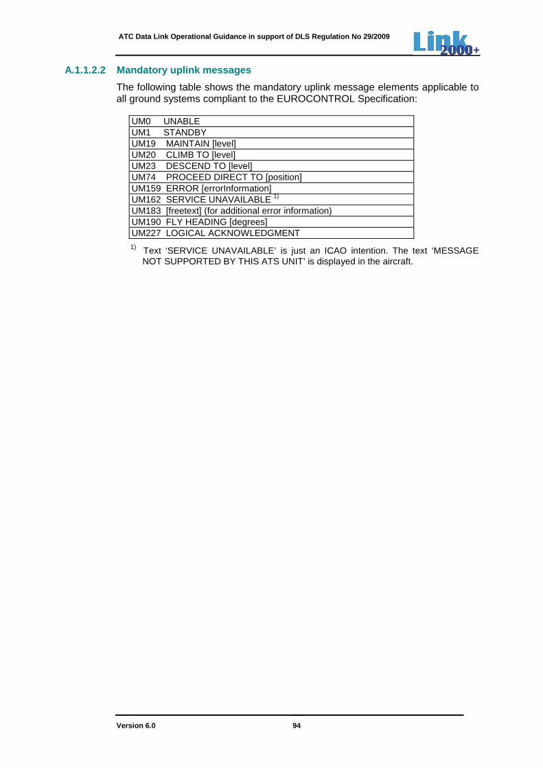
ATC Data Link Operational Guidance in support of DLS Regulation No 29/2009
Version 6.0 94
A.1.1.2.2 Mandatory uplink messages
The following table shows the mandatory uplink message elements applicable to all ground systems compliant to the EUROCONTROL Specification:
UM0 UNABLE UM1 STANDBY UM19 MAINTAIN [level] UM20 CLIMB TO [level] UM23 DESCEND TO [level] UM74 PROCEED DIRECT TO [position] UM159 ERROR [errorInformation] UM162 SERVICE UNAVAILABLE 1)
UM183 [freetext] (for additional error information) UM190 FLY HEADING [degrees] UM227 LOGICAL ACKNOWLEDGMENT 1) Text ‘SERVICE UNAVAILABLE’ is just an ICAO intention. The text ‘MESSAGE
NOT SUPPORTED BY THIS ATS UNIT’ is displayed in the aircraft.
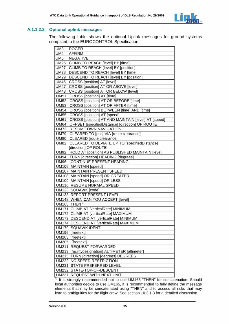
ATC Data Link Operational Guidance in support of DLS Regulation No 29/2009
Version 6.0 95
A.1.1.2.3 Optional uplink messages
The following table shows the optional Uplink messages for ground systems compliant to the EUROCONTROL Specification:
UM3 ROGER UM4 AFFIRM UM5 NEGATIVE UM26 CLIMB TO REACH [level] BY [time] UM27 CLIMB TO REACH [level] BY [position] UM28 DESCEND TO REACH [level] BY [time] UM29 DESCEND TO REACH [level] BY [position] UM46 CROSS [position] AT [level] UM47 CROSS [position] AT OR ABOVE [level] UM48 CROSS [position] AT OR BELOW [level] UM51 CROSS [position] AT [time] UM52 CROSS [position] AT OR BEFORE [time] UM53 CROSS [position] AT OR AFTER [time] UM54 CROSS [position] BETWEEN [time] AND [time] UM55 CROSS [position] AT [speed] UM61 CROSS [position] AT AND MAINTAIN [level] AT [speed] UM64 OFFSET [specifiedDistance] [direction] OF ROUTE UM72 RESUME OWN NAVIGATION
UM79 CLEARED TO [pos] VIA [route clearance] UM80 CLEARED [route clearance] UM82 CLEARED TO DEVIATE UP TO [specifiedDistance] [direction] OF ROUTE UM92 HOLD AT [position] AS PUBLISHED MAINTAIN [level] UM94 TURN [direction] HEADING [degrees] UM96 CONTINUE PRESENT HEADING UM106 MAINTAIN [speed] UM107 MAINTAIN PRESENT SPEED UM108 MAINTAIN [speed] OR GREATER UM109 MAINTAIN [speed] OR LESS UM116 RESUME NORMAL SPEED UM123 SQUAWK [code] UM133 REPORT PRESENT LEVEL UM148 WHEN CAN YOU ACCEPT [level] UM165 THEN 1)
UM171 CLIMB AT [verticalRate] MINIMUM UM172 CLIMB AT [verticalRate] MAXIMUM UM173 DESCEND AT [verticalRate] MINIMUM UM174 DESCEND AT [verticalRate] MAXIMUM UM179 SQUAWK IDENT UM196 [freetext] UM203 [freetext] UM205 [freetext] UM211 REQUEST FORWARDED UM213 [facilitydesignation] ALTIMETER [altimeter] UM215 TURN [direction] [degrees] DEGREES UM222 NO SPEED RESTRICTION UM231 STATE PREFERRED LEVEL UM232 STATE-TOP-OF-DESCENT UM237 REQUEST WITH NEXT UNIT 1) It is strongly recommended not to use UM165 "THEN" for concatenation. Should local authorities decide to use UM165, it is recommended to fully define the message elements that may be concatenated using "THEN" and to assess all risks that may lead to ambiguities for the flight crew. See section 10.3.1.3 for a detailed discussion.
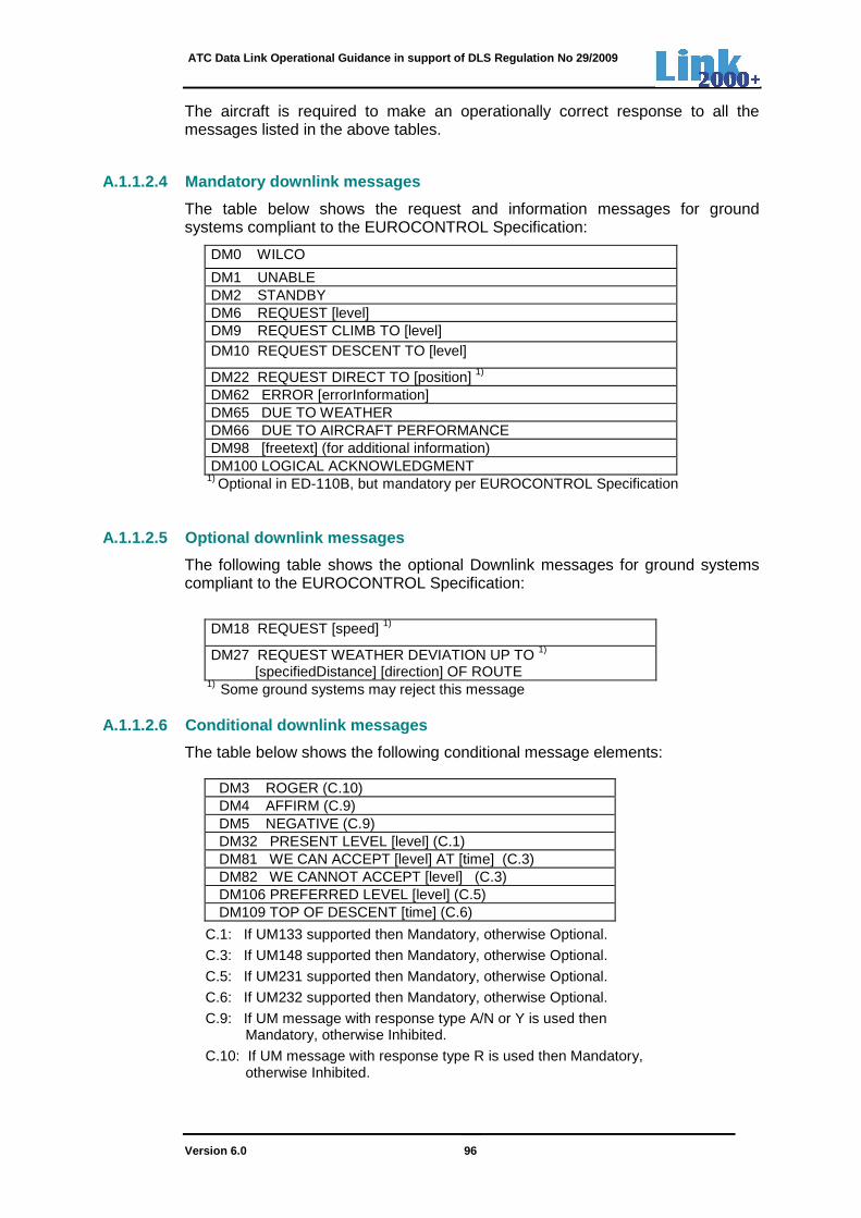
ATC Data Link Operational Guidance in support of DLS Regulation No 29/2009
Version 6.0 96
The aircraft is required to make an operationally correct response to all the messages listed in the above tables.
A.1.1.2.4 Mandatory downlink messages
The table below shows the request and information messages for ground systems compliant to the EUROCONTROL Specification:
DM0 WILCO
DM1 UNABLE DM2 STANDBY DM6 REQUEST [level] DM9 REQUEST CLIMB TO [level] DM10 REQUEST DESCENT TO [level]
DM22 REQUEST DIRECT TO [position] 1) DM62 ERROR [errorInformation] DM65 DUE TO WEATHER DM66 DUE TO AIRCRAFT PERFORMANCE DM98 [freetext] (for additional information) DM100 LOGICAL ACKNOWLEDGMENT
1) Optional in ED-110B, but mandatory per EUROCONTROL Specification A.1.1.2.5 Optional downlink messages
The following table shows the optional Downlink messages for ground systems compliant to the EUROCONTROL Specification:
DM18 REQUEST [speed] 1)
DM27 REQUEST WEATHER DEVIATION UP TO 1) [specifiedDistance] [direction] OF ROUTE
1) Some ground systems may reject this message A.1.1.2.6 Conditional downlink messages
The table below shows the following conditional message elements:
DM3 ROGER (C.10) DM4 AFFIRM (C.9) DM5 NEGATIVE (C.9) DM32 PRESENT LEVEL [level] (C.1) DM81 WE CAN ACCEPT [level] AT [time] (C.3) DM82 WE CANNOT ACCEPT [level] (C.3) DM106 PREFERRED LEVEL [level] (C.5) DM109 TOP OF DESCENT [time] (C.6)
C.1: If UM133 supported then Mandatory, otherwise Optional.
C.3: If UM148 supported then Mandatory, otherwise Optional.
C.5: If UM231 supported then Mandatory, otherwise Optional.
C.6: If UM232 supported then Mandatory, otherwise Optional.
C.9: If UM message with response type A/N or Y is used then Mandatory, otherwise Inhibited.
C.10: If UM message with response type R is used then Mandatory, otherwise Inhibited.
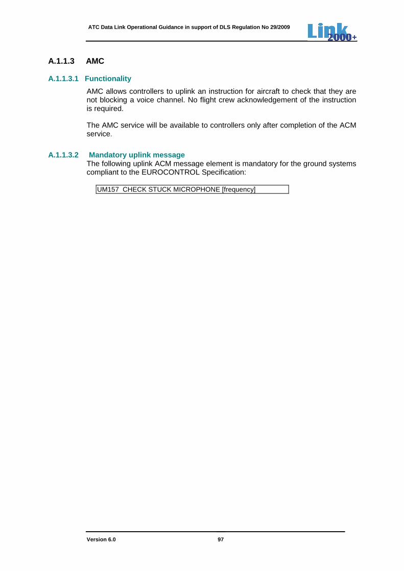
ATC Data Link Operational Guidance in support of DLS Regulation No 29/2009
Version 6.0 97
A.1.1.3 AMC A.1.1.3.1 Functionality
AMC allows controllers to uplink an instruction for aircraft to check that they are not blocking a voice channel. No flight crew acknowledgement of the instruction is required.
The AMC service will be available to controllers only after completion of the ACM service.
A.1.1.3.2 Mandatory uplink message
The following uplink ACM message element is mandatory for the ground systems compliant to the EUROCONTROL Specification:
UM157 CHECK STUCK MICROPHONE [frequency]

ATC Data Link Operational Guidance in support of DLS Regulation No 29/2009
Version 6.0 98
ANNEX B: TIME SEQUENCE DIAGRAMS GROUND-GROUND FORWARDING OF LOGON DATA
The following time-sequence diagrams are presented:
• Figure 1: Ground-ground forwarding of logon data, using LOF, during transfer of ATC communications.
• Figure 2: Air-ground forwarding of logon data, using CM-contact, during transfer of ATC communications.
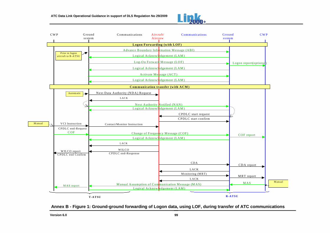
ATC Data Link Operational Guidance in support of DLS Regulation No 29/2009
Version 6.0 99
Aircraft/A ircrew
C om m unications G roundsystem
C W PCom m unications
R -ATSUT -AT SU
G roundsystem
CW P
L ogon Forw arding (w ith L O F)
C om m unication transfer (w ith A CM )
CPD LC start confirm
Contact/M onitor Instruction
CD ACD A report
M onitoring (M R T)M R T report
Advance B oundary Information M essage (AB I)
Activate M essage (ACT )
M anual A ssum ption o f C om m unication M essage (M AS)Logical Acknow ledgem ent (LA M )
M A S
Prior to logonaircraft to R -ATSU
M anual
M anual
N ext A uthority N otified (N AN )Logical Acknowledgem ent (LA M )
Log-O n Forward M essage (LO F)
Logical Acknowledgem ent (LA M )
Logical Acknowledgem ent (LA M )
Logical Acknowledgem ent (LA M )
N ext D ata A uthority (N D A ) Request
LAC K
Autom atic
CPD LC start request
C O F
Logical Acknowledgem ent (LA M )
LAC K
LACK
Logon report(optional)
CPDLC end ConfirmW ILC O report
Change o f Frequency M essage (CO F)
V CI Instruction
CPDLC end-R equest
W ILC OC PDLC end-Response
LAC K
M AS report
CO F report
Annex B - Figure 1: Ground-ground forwarding of Log on data, using LOF, during transfer of ATC communic ations
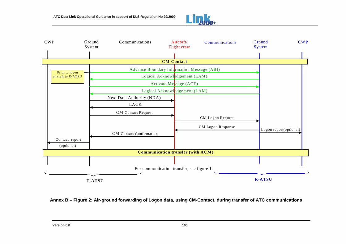
ATC Data Link Operational Guidance in support of DLS Regulation No 29/2009
Version 6.0 100
Aircraft/ Flight crew
CM Logon Request
Communications Ground System
CWP
CM Logon Response Logon report(optional)
Communications
R-ATSU T-ATSU
Ground System
CWP
CM Contact
Contact report
CM Contact Confirmation
Communication transfer (with ACM )
Advance Boundary Information Message (ABI)
CM Contact Request
Prior to logon aircraft to R-ATSU
(optional)
For communication transfer, see figure 1
Next Data Authority (NDA)
LACK
Logical Acknowledgement (LAM)
Logical Acknowledgement (LAM)
Activate Message (ACT)
Annex B – Figure 2: Air-ground forwarding of Logon data, using CM-Contact, during transfer of ATC comm unications

ATC Data Link Operational Guidance in support of DLS Regulation No 29/2009
Version 6.0 101
ANNEX C: URGENCY, ALERT AND RESPONSE ATTRIBUTES
Each message element attribute table entries are listed in order of precedence (i.e. a precedence value of 1 is highest followed by 2, etc). When a message contains multiple message elements, the highest precedence message element attribute type associated with any element in the message is the message attribute for each attribute type for the entire message. (e.g.: the concatenation of UM20 (W/U) with UM222 (R) - CLIMB TO [level] NO SPEED RESTRICTION - will have the response attribute of the UM20 - W/U.)
As indicated in 4.2, the use of Alert and Urgency (prioritisation of CPDLC messages) attributes is a local implementation option.
C.1 URGENCY
The urgency attributes delineate the queuing requirements for messages received. They are as follows:
Type Description Precedence
D Distress 1 U Urgent 2 N Normal 3 L Low 4
C.2 ALERT
The alert attributes delineate the type of alerting required upon message receipt. They are as follows:
Type Description Precedence
H High 1 M Medium 2 L Low 3 N No alerting required 4
C.3 RESPONSE
Each uplink message element shall have associated Response attributes with precedence as shown in the table below:
Type Response
Required Valid responses Precedence
W/U Yes WILCO, UNABLE, STANDBY, NOT CURRENT DATA AUTHORITY, NOT AUTHORISED NEXT DATA AUTHORITY, LOGICAL ACKNOWLEDGMENT (only if required), ERROR
1

ATC Data Link Operational Guidance in support of DLS Regulation No 29/2009
Version 6.0 102
A/N Yes AFFIRM, NEGATIVE, STANDBY, NOT CURRENT DATA AUTHORITY, NOT AUTHORISED NEXT DATA AUTHORITY, LOGICAL ACKNOWLEDGMENT (only if Required), ERROR
2
R
Yes ROGER, UNABLE, STANDBY, NOT CURRENT DATA AUTHORITY, NOT AUTHORISED NEXT DATA AUTHORITY, LOGICAL ACKNOWLEDGMENT (only if required), ERROR
3
Y Yes LOGICAL ACKNOWLEDGMENT (only if Required)
4
N No, unless LACK element required
LOGICAL ACKNOWLEDGMENT (only if Required), NOT CURRENT DATA AUTHORITY, NOT AUTHORISED NEXT DATA AUTHORITY, ERROR
5
Each downlink message element shall have associated Response attributes with precedence as shown in the table below:
Type Response required
Valid responses Precedence
Y Yes Any CPDLC uplink message, LOGICAL ACKNOWLEDGEMENT (only if Required)
1
N No, unless LACK element Required
LOGICAL ACKNOWLEDGEMENT (only if Required), SERVICE UNAVAILABLE, FLIGHT PLAN NOT HELD, ERROR
2
ATC Data Link Operational Guidance in support of DLS Regulation No 29/2009
Version 6.0 103
ANNEX D: OVERVIEW CRO SYSTEM PERFORMANCE AND PROBLEM REPORTING
D.1 Scope
EC Regulation 29/2009 [1] requires that data link system performance is regularly monitored to verify that an acceptable level of safety and conformance with the level of performance required continues to be met. The Central Reporting Office (CRO), established within EUROCONTROL’s Network Management Directorate, functions as focal point for:
• Monitoring system performance; • Investigating system-level problems; • Facilitating the sharing of knowledge among the data link community.
To perform its functions, the CRO will routinely need data from both the ACSPs and the ATSPs as well as problem reports from all stakeholders. It will create a set of regular performance monitoring reports and a shared knowledge of problem resolutions via the problem reporting database as well as more generic descriptions of common problems/resolutions on the Link wiki.
D.2 Performance monitoring
A set of reports, agreed between each ANSP and each National Safety Authority, allow the ANSPs to monitor the quality of service as required under the EC Regulation No 29/2009. The set of reports from ANSPs contains performance data at:
a) CPDLC-and CM application to be created monthly. b) at application- or ATN transport layer to verify general system health on regular
or ad-hoc basis. In addition, the CRO receives data in relation to VDLM2 communication primarily from ACSPs for capacity planning and problem investigation and also receives some complementary data from ANSPs.
The CRO regularly publishes ATM network level performance monitoring reports on the CRO wiki (http://www.eurocontrol.int/link2000/wiki/index.php/Main_Page). The reports, created at ANSP or Aircraft Operator level are restricted to the relevant user and EUROCONTROL.
D.3 Problem Reporting, investigation and resol ution
Link stakeholders are expected to perform their own investigations of any problems found. The CRO provides a database system for reporting problems and investigates those that cannot be resolved locally (e.g. by the ANSP for a problem reported by an Air Traffic Controller). In order to promote knowledge sharing across the Link2000+ community, all system problems should be recorded in the CRO problem reporting database (https://www.eurocontrol.int/ticketingservices/secure/Dashboard.jspa) and be made accessible to all registered users. The CRO core team will identify any commonly occurring problem in a generic way and publish them on the LINK2000+ wiki as means of information sharing. For more details on the CRO functions, refer to the LINK2000+ website: http://www.eurocontrol.int/services/link-2000-programme.
ATC Data Link Operational Guidance in support of DLS Regulation No 29/2009
Version 6.0 104
ANNEX E: SERVICE PROVISION TO FANS 1/A(+) AND BILINGUAL AIRCRAFT
Some ANSPs (NATS, MUAC, NAV-P, IAA) have accommodated their ground systems to allow the provision of CPDLC services to FANS 1/A aircraft and FANS 1/A+ aircraft. ANSPs (NATS, NAV-P, IAA) at the NAT/EUR Continental boundary allow seamless transfer to bilingual aircraft, equipped as integrated FANS 1/A+ and ATN-B1 stacks.
Note 1: FANS 1/A+ aircraft have implemented the Latency Time Monitor (LTM) mechanism to satisfy ED120 safety requirement SR-ACL-13 for profile changing messages, while FANS 1/A aircraft exclude this.
Note 2: For details on FANS 1/A(+) aircraft, refer to GOLD-Ed 2.0 [15] The EUROCAE ED154A document [9] provides Interoperability requirements for:
a) ATN-B1 ground systems, allowing the accommodation of FANS 1/A+ aircraft;
b) Ground- and aircraft systems (FANS 1/A+ or ATN-B1), allowing the seamless transfer of bilingual aircraft, equipped as integrated FANS 1/A+ and ATN-B1 stacks.
FANS 1/A (+) Aircraft
Safety analysis has demonstrated that the absence of some safety-critical properties of FANS 1/A(+) aircraft implementations require some additional mitigations. The Table below lists the differences with reference to ATN-B1 implementations and provides system- and procedural mitigations, when providing CPDLC services to FANS 1/A(+) aircraft.

ATC Data Link Operational Guidance in support of DLS Regulation No 29/2009
Version 6.0 105
Difference Mitigation
No downlink of DM99 CURRENT DATA AUTHORITY
After the controller has assumed the flight, the ATSU should:
Either,
generate an internal CDA message and then uplinks free text message UM169 containing ICAO facility designation, facility name and facility function (as for ATN-B1 aircraft).
Or,
Uplink a free text ‘Welcome’ message UM169, requiring the flight crew to respond with ROGER
Example: BAW126 WELCOME TO LONDON RESPOND CPDLC ROGER
No Flight Identification in message application checksum
Some ATSUs may prepend the Flight Identification, using free text message UM169, to each uplink message.
No distinction between FANS 1/A and FANS 1/A+ aircraft in logon request or FPL
The ATSU does not uplink free text message UM169 to a FANS 1/A+ aircraft, instructing the pilot to set Latency Time Monitor (40s), but relies on ground timer tts (120s).
Upon time-out of ground-timer tts:
Either,
The ATSU should automatically generate a commanded termination (reason code 5) which will terminate CPDLC with that aircraft for the duration of the flight for which the ATSU is CDA, and,
The controller should return to voice, instructing the flight crew to disconnect CPDLC for the duration of the flight for which the ATSU is CDA.
Or,
The controller should return to voice to clarify the situation. If no message is received, the controller should instruct the flight crew to disconnect CPDLC for the duration of the flight for which the ATSU is CDA.
Bilingual Aircraft Two types of dual FANS 1/A+ and ATN aircraft implementations exist, requiring different procedures:
a) Integrated FANS and ATN At initial logon, in NAT airspace, a bilingual aircraft sets itself automatically in ‘FANS’ mode, while in Continental European airspace, the aircraft sets itself automatically in ‘ATN’ mode. Note: Upon initial logon, the aircraft system checks whether a CM-address can be found. If so, the aircraft sets the DL functions in ATN mode. If not, the aircraft sets the DL functions in FANS mode. For flights, crossing the boundary of the NAT/EUR Continental region, seamless DL transfer between the ACCs at the NAT/EUR Continental airspace (NATS, NAV-P, IAA) is possible, provided the interoperability requirements as specified in ED-154A/Chapter 4 [9] are implemented. AOs and ANSPs do not require other procedures than those specified in GOLD ED 2.0 [15] and the LINK2000+ Operational guidances.

ATC Data Link Operational Guidance in support of DLS Regulation No 29/2009
Version 6.0 106
b) Bilingual aircraft (independent FANS and ATN) When departing, before initial logon, the flight crew needs to manually set the DL functions either in FANS or ATN mode, followed by a manual logon by the flight crew to the first ACC. It is not possible to use the applications at the same time. For flights crossing the boundary of the NAT/EUR Continental region, no seamless DL transfer between the NAT ACC and EUR Continental ACC is possible. When the aircraft is flying into the EUR Continental region or departs from an airport within the EUR Continental region, the flight crew must manually set the DL functions into ATN mode, followed by a manual logon to the ATN-based ACC. Likewise, when the aircraft is flying into a Non-EUR Continental region or departs from an airport outside the EUR Continental region, the flight crew must manually set the DL functions into FANS mode, followed by a manual logon to the FANS-based ACC.
Both CPDLC applications make use of the same attention getters.
The display of messages on the HMI is slightly different between independent ATN-B1 and FANS 1/A systems as is presented in the table below. As may be concluded, the differences are not significant and should be easily understood by the flight crew. The differences should not cause confusion or interpretation issues, provided flight crews are trained in both FANS 1/A and ATN B1 system operation.
Uplink Message Number (UM#)
FANS 1/A Message Element and Display Format
ATN Message Element and Display Format
20 CLIMB TO AND MAINTAIN [altitude]
CLIMB TO [level]
23 DESCEND TO AND MAINTAIN [altitude]
DESCEND TO [level]
96 FLY PRESENT HEADING CONTINUE PRESENT HEADING
133 CONFIRM ALTITUDE REPORT PRESENT LEVEL
162 SERVICE UNAVAILABLE MESSAGE NOT SUPPORTED BY THIS ATS UNIT
ATC Data Link Operational Guidance in support of DLS Regulation No 29/2009
Version 6.0 107
APPENDIX A: LIST OF CONTRIBUTORS Chairman:
Dissing, Søren EUROCONTROL (HQ)
Secretary:
Brondsema, Willem EUROCONTROL (HQ)
Members: Bolander, Sylvie DSNA/DTI
Breting, Lisa NAVIAIR
Carlsson, Goran SAS
Carretero, Fortunato NAV-Portugal
Daems, Daniel EUROCONTROL (MUAC)
Dehn, Doris EUROCONTROL (HQ)
Diez, David AENA - Madrid
Gelabert, Jordi AENA - Barcelona ACC
Gheorghe, Augustin EUROCONTROL (HQ)
Lesch, Jörg DFS – ACC Karlsruhe
Lezerat, Olivier Airbus
Manzano, Jordi Air-Europa
Milan, Korab ANSP-CZ
Monteil, Olivier DSNA/DO Marseille
Most, Christine EUROCONTROL (IANS)
McGuffin, Tom Honeywell
Ozé, Stefan EUROCONTROL (CRDS-Budapest)
Schuen-Medwed, Renée EUROCONTROL (CRDS-Budapest)
Skov, Finn NAVIAIR (Denmark)
Stuhlsatz, Volker EUROCONTROL (MUAC)
Teyssandier, Olivier DSNA/DO
Villwock, Hartmut DFS-Langen
Vogel, David Skyguide


