33
Ferry Terminal Design
Ferry Terminal Design

TDM | ENGINEERING DESIGN CODE2
In this chapter
Introduction 3
Purpose 3
2.1 Terminals 3
2.2 Good design principles 4
2.3 Standards 5
Terminal ownership and operation 6
Terminals catagorisation 6
4.1 Type 1: Unstaffed rural, suburban or urban wharf 6
4.2 Type 2: Staffed suburban or urban terminal 8
4.3 Type 3: Staffed city centre or destination terminal 8
Terminal design 9
5.1 Terminal entrances and concourses 10
5.2 Ramps and pontoons 10
5.3 Ferry vessels 17
5.4 Terminal signage, wayfinding and identity 17
5.5 Passenger Information Displays (PIDs) and customer information 18
5.6 Cycling 19
5.7 Terminal space planning 19
5.8 Ramps 23
5.9 Design life for terminal components 24
5.10 Maintainability of terminal elements 25
5.11 Cost-effectiveness of design 26
5.12 Acoustics 26
5.13 Security 28
5.14 Sustainability 31
5.15 Constructability 31
5.16 Reliability/availability of critical plant and equipment 32
5.17 Designing for safety 32
5.18 Storage facilities at terminals 32
5.19 Detailing 33
5.20 Hazards and risks 33
01
02
03
04
05

3
Ferry terminal
design
Introduction
Terminology used and/or applied in this manual is defined as follows:
A generic term that encomposes the full range of landside ferry facilities from a large ferry terminal with many amenities like Downtown Ferry Terminal to a simple floating pontoon and access way like Beach Haven Wharf.
Mana Whenua describes the rights and responsibilities an iwi or hapu holds over their ancestral lands.
A current unforeseen or unplanned event that has life threatening or extreme loss implications and requires immediate attention.
A reduced level of service invoked by equipment outage or malfunction, staff shortage or procedures becoming inadequate as a knock-on effect of one or several deficient system elements.
The condition under whicferry services are designed to operate. This includes peaks, e.g. rush hours and troughs in demand experienced during the day.
The Fruin Levels of Service is a concept used in the design of places of public assembly. It utilises a typical body ellipse to represent the space occupied by a person without touching an adjacent person
PurposeThe purpose of this chapter of the Auckland Design Manual is to define the way in which passenger capacity, functionality and operability is to be achieved in ferry Terminal design to meet customer expectations.
2.1 Terminals
Terminals are the public gateways to the Auckland ferry network. The way in which they are designed and presented influences the behaviour on, and the perception of the ferry system for both passengers and staff. The quality of Terminal design has the ability to raise the level of confidence in the ferry system as a whole and with it an increase in patronage and revenue.
Terminals shall be designed to specifically respond to the needs of form, function and personality where the functionality is prescribed by the requirements set out in this document, where the form is set out by the appropriate response to the relationship of the operational and architectural elements of the buildings in their setting and where the personality is directly derived from visual expression and customer experiences of the materials, spacial composition and the context within which they have been used.
01
TERMINAL
MANA WHENUA
EMERGENCY SITUATION
DEGRADED OPERATION
NORMAL OPERATION
FRUIN LEVEL OF SERVICE
02PURPOSE

TDM | ENGINEERING DESIGN CODE4
Ferry terminals and wharfs occupy a valued waterfront location and the local community often sees them as a neighbourhood recreation facility. Where feasible, design can allow for community use for passive recreation but should not facilitate swimming and diving (safety concerns) or fishing (safety, cleanliness, access concerns). Design must take into account local sea and weather conditions and the vessels to be used and provide what is needed to minimise chances for damage to the wharf structure or to the ferry vessel and to avoid the possibility of injury to crew or passengers.
2.2 Good design principles
The following are the stated good design principles to be employed in determining the appropriate design response for all Terminals on the Auckland Transport ferry network
Well planned Terminal footprints that optimize passenger comfort, satisfaction and safety
The use of attractive and maintainable materials that offer the optimum balance between capital and whole of life cost analysis
Safe and secure spaces that avoid hidden and difficult to monitor areas and that include good visual links and strong passive surveillance with clear legible signage
A cohesive and linked network which is easy to understand and navigate and one that does not rely upon signage to determine what must be intuitive use of public space; integrates different transport modes, providing direct connections and easy transitions
Main access routes are obvious and accessible to all members of the community, whether able bodied or mobility impaired, without barriers of differentiation
Support pedestrian links across transport corridors, pathways and usable public Urban Realm space around major roads and ferryway reservations
Promote positive environmental, social, cultural and economic values; recurrent cost savings
Reflect and respond to diverse community values and encourage positive interaction
Support and encourage communities, connecting nearby facilities, incorporating shops, art, recreation spaces
Respond to specific local landscape, topography and orientation
Respond to history, memory, understanding of and continuity with the past
Relevant across life-spans of many generations; representative of its time and of a high quality
Finishes that are easy to maintain and will age gracefully without the need for premature replacement
FUNCTIONAL
SAFE, LEGIBLE
SEAMLESS
UNIVERSALLY INCLUSIVE
WALKABLE
SUSTAINABLE
ENGAGING
SOCIALLY RESPONSIVE
SITE RESPONSIVE
VALUING HERITAGE
ENDURING
DURABLE

5
Ferry terminal
design
Create a desire to experience and delight in the journey rather than just pass though
Authentic, genuinely sensitive and intelligent in design of form, space, proportion, craft and detail
Capable of being operated efficiently with the minimum practical human intervention under normal and disrupted operating conditions
Capable of being inspected, monitored, cleaned, serviced, and replaced as necessary without untoward disruption to Terminal operations and where practicable, being capable of being undertaken during normal operating hours. Parts and materials to be locally sourced where practicable to avoid extended delivery times for maintenance items from overseas.
ENJOYABLE
DELIGHTFUL
OPERABLE
MAINTAINABLE
2.3 Standards
This Design Manual consolidates New Zealand ferry and building standards, adopts international best practice in the absence of applicable local standards, and provides space planning guidelines for Terminals and Terminal precincts, including but not limited to:
The following standards have been consulted in the preparation of this design guide and should be applied:
• AS 4997 -2005 Guidelines for the design of maritime structures
• AS 3962-2001 Guidelines for the design of marinas
• PIANC guidelines for the design of fender systems 2002
• NSW Government Guidelines for the design of maritime structures
• Auckland Transport Ferry Common Elements Specification.
STANDARDS

TDM | ENGINEERING DESIGN CODE6
Terminal ownership and operation
Terminals shall be assumed to be owned, operated and maintained by Auckland Transport or agents acting on behalf of Auckland Transport unless in a private marina where the access agreement will define ownership and responsibilities.
Terminals on the Auckland ferry network shall be designed to operate 365 days per year with all planned maintenance activities for Terminals to be carried out during either off peak operational hours, where this does not interfere with Terminal operations or within limited non-traffic hours each night or at a weekend.
Terminals catagorisation
In order to define the Terminal requirements for design purposes in relation to size and complexity of the facility it is necessary to establish 3 generic categories
An unstaffed rural, suburban or urban wharf for recreational or limited PT service
A staffed suburban or urban ferry terminal regularly serviced by a contracted PT service
A city centre or major destination ferry terminal
All Terminals are to be designed as interchanges with provision for connecting bus services
The following sections describe the default minimum level of Terminal facilities expected at each of the Terminal types, in the absence of any specific overriding design requirements emerging from the Auckland Transport project specific design brief.
4.1 Terminal Type 1 Unstaffed rural, suburban or urban wharf
Type 1 Terminals are relatively low patronage Terminal locations but with the potential to grow over time. This potential growth shall be factored into the space planning of the Terminal design.
Type 1 Terminals shall:
• Provide full mobility access
• Provide canopy, enclosed gangway or other suitable shelter structure for waiting passengers
• Provide accommodation for at least 50 people with at least 10 seated
03
04
TYPE 1
TYPE 2
TYPE 3
DESCRIPTION
REQUIREMENTS

7
Ferry terminal
design
• Provide boarding platforms a minimum of 2 metres wide and 3 meters deep at standard freeboard heights of (900mm 1400mm, 1800mm) to provide near level boarding to the current ferry fleet and standard vessels specified under PTOM
• Provide adequate fendering and mooring systems to allow design size vessels to safely berth in all weather conditions
• Provide marine-grade non-slip surfacing resistant to scuffing by vessel gangways
• Provide a safe passanger environment, fenced and gated to the fullest extent posisble to prevent accidential or unauthorised entry to water
• Provide liferings and emergency ladders
• Provide LED lighting to provide a safe level of brightness at all times
• Provide full CCTV coverage for operational and passanger safety puposes
• Provide a Public Adress system for customer service and safety announcements
• Provide Emergency Help Points connected to the Auckland Transport Operations Centre (ATOC)
• Provide Passanger Information Display screens (PIDS) showing real time service information
• Provide AT WiFi connectivity
• Provide for advertising screens to beinstalled by AT’s advertising partners
• Provide AT HOP card validators (where AT HOP is utilised on services using the facility)
• Provide Terminal name sign easily visible from land and water, Terminal location map and wayfinding signage to/from Terminal
• Provide suitable shore supply for vessel layover incl. ducts and pipework for wash-down and multi-type/volt power connection(s)
• Provide suitable storage facilities to meet ferry operator requirements
• Provide litter and recycling bins
• Provide timetable and customer information boards
• Provide safety compliance signage
• Provide cycle storage for a minimum of 10 cycles
• Provide landside connections including shelter for bus services (where they are provided)
• Provide car drop off point
• Provide a means of closing the Terminal to public access after the last ferry service of the day.

TDM | ENGINEERING DESIGN CODE8
4.2 Terminal Type 2 Staffed suburban or urban terminal
Type 2 Terminals have a higher patronage than the type 1 Terminal and are required to have a increased level of passenger facilities. They should provide a high quality Terminal environment with a full or part time staffed presence to enhance the customer experience and increase the degree of personal security throughout normal Terminal operating hours
Type 2 Terminals should provide for all elements of a Type 1 Terminal plus:
• Provide a fully enclosed waiting room with suitable HVAC and seating to accommodate a of minimum of 100 people with a minimum of 20 seated.
• Provide a retail area accessible from the paid and unpaid areas offering food and beverage services
• Provide toilets
• Provide AT HOP top up machine
• Provide multiple AT HOP validators or AT HOP gateline with a wide gate for mobility impaired and a manual gate
• Provide cycle storage for a minimum of 25 cycles
• Provide drinking water fountain / bottle filler
• Provide staff welfare facilities
• Provide drop off and pick up 5 minute waiting restricted vehicle parking bays
• Provide one maintenance vehicle bay shared with refuse truck bay.
4.3 Terminal Type 3 Staffed city centre or destination terminal
A high quality destination Terminal facility where the primary function is to cater for large passenger volumes both commuter and tourist. Whilst commuter dwell time is relatively short the passenger volumes are such that space planning of the Terminal interiors, circulation and pontoon widths must take into account to ensure customer safety and comfort levels.
The Terminal may include extensive retail facilities that include food and beverage provision through to a small metro style supermarket and speciality shops. The retail facilities can be considered as attractions in their right own for tourists and locals alike and act as attractors to the ferry network.
Type 3 Terminals should provide for all elements of a Type 2 Terminal plus:
• Provide a fully enclosed waiting room with suitable HVAC and seating to accommodate a minimum of 200 people with a minimum of 50 seated per pier
• Provide Customer Service Centre / ticket office selling a full range and tickets and providing customer assistance and AT HOP top up
DESCRIPTION
REQUIREMENTS
DESCRIPTION
REQUIREMENTS
9
Ferry terminal
design
• Provide tourist information services (counter or information board)
• Provide separate male, female, and unisex toilets and baby changing facilities (number based on forecast future demand at location)
• Provide left luggae facility
• Provide AT HOP gateline with a wide gate for mobility impaired and a manual gate
• Provide cycle storage facility for a minimum of 100 cycles
• Provide a cash machine (ATM)
• Provide bus interchange and two ferry replacement bus bays
• P5 stops within close proximity.
Terminal design
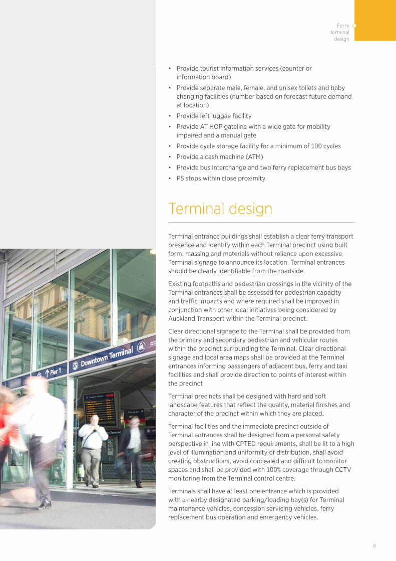
Terminal entrance buildings shall establish a clear ferry transport presence and identity within each Terminal precinct using built form, massing and materials without reliance upon excessive Terminal signage to announce its location. Terminal entrances should be clearly identifiable from the roadside.
Existing footpaths and pedestrian crossings in the vicinity of the Terminal entrances shall be assessed for pedestrian capacity and traffic impacts and where required shall be improved in conjunction with other local initiatives being considered by Auckland Transport within the Terminal precinct.
Clear directional signage to the Terminal shall be provided from the primary and secondary pedestrian and vehicular routes within the precinct surrounding the Terminal. Clear directional signage and local area maps shall be provided at the Terminal entrances informing passengers of adjacent bus, ferry and taxi facilities and shall provide direction to points of interest within the precinct
Terminal precincts shall be designed with hard and soft landscape features that reflect the quality, material finishes and character of the precinct within which they are placed.
Terminal facilities and the immediate precinct outside of Terminal entrances shall be designed from a personal safety perspective in line with CPTED requirements, shall be lit to a high level of illumination and uniformity of distribution, shall avoid creating obstructions, avoid concealed and difficult to monitor spaces and shall be provided with 100% coverage through CCTV monitoring from the Terminal control centre.
Terminals shall have at least one entrance which is provided with a nearby designated parking/loading bay(s) for Terminal maintenance vehicles, concession servicing vehicles, ferry replacement bus operation and emergency vehicles.
TDM | ENGINEERING DESIGN CODE10
Terminals shall be designed to permit commercial development opportunities for spaces above and beside the Terminal footprint and take account of planned developments in the vicinity of Terminal footprints. Space proofing for additional structure shall be provided within the Terminals to support commercial development. Sequencing and crash deck protection of the Terminal facility to enable commercial development provision shall be taken into account in the design and construction of the Terminal to have the least impact upon the operational Terminal environment and operational timetable.
5.1 Terminal entrances and concourses
Terminal entrances and concourses are typically the busiest spaces in a Terminal footprint and their design needs to recognise the important part that they play in establishing the customer environment for the ferry experience. These spaces shall be designed with generous headroom and this, as expressed through the external form of the building, will serve to heighten the presence of the Terminal within the precinct. Note the Terminal entrance is also the location where passengers are held away from the ferry operational environment during periods of ferry service disruption as part of the Terminal crowd management plan
Terminal entrances must be designed for generous floor areas and where passenger congestion is to be avoided by adopting international benchmarks for space planning around key functional elements. Space shall be provided for retail units to activate the surrounding street and the internal Terminal environment as an integral part of the customer service provision of facilities.
The use of maximum transparency is desireable within the entrance building as this enhances the personal security of those using both the internal and external space to see and be readiliy seen around and within the Terminal.The external envelope transparency and the consistently high levels of artificial lighting at 160 lux required within the Terminal should be fully exploited in the design, increasing the prominence of the entrance building in the local environment during the hours of darkness.
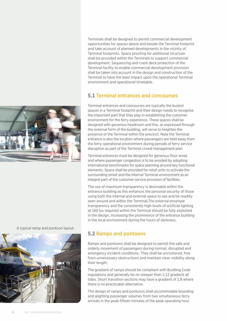
5.2 Ramps and pontoons
Ramps and pontoons shall be designed to permit the safe and orderly movement of passengers during normal, disrupted and emergency incident conditions. They shall be uncluttered, free from unnecessary obstructions and maintain clear visibility along their length.
The gradient of ramps should be compliant with Buidling Code regulations and generally be no steeper than 1:12 gradient all tides. Short transition sections may have a gradient of 1:8 where there is no practicable alternative.
The design of ramps and pontoons shall accommodate boarding and alighting passenger volumes from two simultaneous ferry arrivals in the peak fifteen minutes of the peak operating hour
A typical ramp and pontoon layout
11
Ferry terminal
design
in the design year, achieve a FRUIN Level of Service C and clear all alighting passengers from the ferry operational area in under 2.5 minutes.
All Terminal layouts are to be designed for the simultaneous arrival of ferrys at each berth and the passenger surges this creates in circulation.
Ramps and Pontoons are to meet all other Ferry Terminal TDM requirements.
5.2.1 Engineering considerations
Dead load for the floating pontoon system shall include all framing, decking, connection, flotation units, and all permanently attached equipment such as pipes, services modules, gangway and landing platform.
The floating pontoon system shall be designed for either of the following live loads, whichever produces the most adverse effect:
• A uniformly distributed load over the deck plan of 3.0kPa, or
• A concentrated load of 4.5kN.
The structural system for gangway shall be designed for either of the following live loads, whichever produces the most adverse effect:
• A vertical uniformly distributed load over the width and length, of 5.0kPa, or
• A concentrated load of 4.5kN
• A load on the handrail on one side of 0.75kN/m acting inward, outward or downward which produces the most adverse effects
• Wind drag and uplift forces.
The floating pontoon system shall be designed for stability live loads of:
• 2.0kPa applied across half the width of the pontoon; and
• 2.0kPa applied over the width and length of the gangway.
Wind loads are applied directly to the floating pontoon system and indirectly through the action of wind on moored vessels. An ultimate 3 second gust design wind speed of 45m/s shall be used for the pontoon design (i.e. V500 for Auckland from Table 3.1 of AS/NZS 1170.2:2011). Applied wind loads on the berthed vessels and pontoon, shall be based on the equivalent 30 second steady state wind, and assuming a vessel occupies each berth, and shall generally be determined in accordance with the Australian Standard “Guidelines for the design of Marinas” AS 3962. The wind profile areas and drag coefficient for calculations of wind loads on the design vessels shall be as nominated in the Australian Standard AS 3962 for the Design Vessel.
The floating pontoon shall be designed for a significant wave height of 1.0m with wave period of 3-4s. The maximum wave height shall be taken as 1.86m.
DESIGN DEAD LOADS
DESIGN VERTICAL LIVE LOADS
STABILITY LIVE LOADS
WIND LOADS
WAVE LOADS

TDM | ENGINEERING DESIGN CODE12
In addition, the floating pontoon shall be designed for a boat wake of maximum wave height of 0.8m and period of approximately 5 seconds.
The floating pontoon system shall be designed to withstand without damage the loads applied to the pontoon due to berthing impacts of the design vessel.
A design approach speed for the design vessel of not less than 0.2 m/s perpendicular to the pontoon shall be adopted (ref to DTFT Operation Manual(s) for vessel berthing procedures).
Mooring loads shall be determined in accordance with AS 2962
Possible combinations of dead load, vertical and horizontal loads shall be considered in the design.
The following levels reduced to Chart Datum (CD) shall apply:
Highest recorded tide +4.128m CD
H.A.T. +3.65m CD
M.H.W.S. +3.32m CD
M.S.L. +1.86m CD
M.L.W.S. +0.42m CD
L.A.T. +0.00m CD
Structures shall be designed to allow for future sea level rise caused by global warming. Long term sea-level rise must be assumed as 1m as per the Auckland Unitary Plan. Refer to NZ Ministry for the Environment publication Preparing for Coastal Change – A summary of coastal hazards and climate change guidance for local government December 2107
Auckland Transport standard freeboard levels are:
• 900mm
• 1400mm
• 1800mm.
The freeboard to the top surface of the floating pontoon under the design dead load plus the uniformly distributed load vertical live load, including the dead and live load reactions of the gangway, shall be generally as stated above. The floating pontoon shall be designed to float level under dead load within the following tolerances:
Maximum longitudinal slope 1%
Maximum transverse slope 2%
When the design stability live load is applied to half width of the pontoon and the full length and width of the gangway, the minimum freeboard shall not be less than 600mm. The complete bottom of the pontoon shall remain submerged under these conditions.
The criteria for vertical and stability freeboards shall be satisfied under the worst combination of live loadings on any or all points of the pontoon and/or on the ramp.
BERTHING IMPACT
MOORING LOADS
LOAD COMBINATIONS
TIDE LEVELS
SEA LEVEL RISE
STANDARD ATFREEBOARD LEVELS
STABILITY

13
Ferry terminal
design
The flotation units shall be of such a design as to remain positively buoyant following any damage, such as puncturing, to their protective surfaces.
The deck surface finish on the pontoon system, the gangway, landing platform and ramps shall be a non-skid finish.
Pontoon concrete surfaces to be brush finished with trowelled edges.
Infill panels shall also have a non-skid finish.
The protective surfaces shall be resistant to exhaust heat, fire, marine organism and petrochemical attack.
Mooring cleats/bollards shall be provided which resist the mooring line forces resulting from the action of wind and waves on the design vessels.
Cleats shall be provided at a maximum spacing of 6m interval unless shown otherwise on the Drawings.
The mooring cleats shall be large enough to accommodate the normal diameter of mooring lines for the design vessels. The mooring cleats shall have a design capacity of at least 100kN.
Mooring cleats/bollards are to be positioned on multiple levels where landing structures cater for multiple freeboards.
Cleats to be fitted with back plates to prevent ropes from entering pile guides or guide cover plates.
Pile guides shall be provided which adequately transfer the forces arising from the action of wind, wave and of vessels berthing from the floating pontoon to the piles.
Where located at the end of the pontoon, pile guides shall be surrounded by a protective frame.
The design of the pile guides shall enable a tolerance in the centre-line position of the piles of 50mm at mean tide level and an out-of-verticality of 1 in 150 maximum.
All pontoon anchor pile guides/collars are to be internal. External type piles guides/collars shall not be used on any of the berthing faces or pontoon corners.
Guides are to permit minimal later movement but still allow for sufficient vertical movement without binding.
Pile guide apertures are to be cover plated (checker plate as per Pier 4) with minimal gap between plate and PE pile sleeve.
Vertical fenders shall be provided for impact, chafing and abrasion protection of berthed vessels and pontoon edges at 2.5m centres along the berthing face of the pontoon, unless specified otherwise
Vertical fenders are to extend 1.65m above the pontoon deck level.
The vertical fenders shall be designed to resist the impact forces from the berthing vessel. The selected fenders shall be robust, durable and shall not mark the hulls of vessels.
POSITIVE BUOYANCY
DECK FINISH
MOORING CLEATS/BOLLARDS
PILE GUIDES
VERTICAL FENDERS

TDM | ENGINEERING DESIGN CODE14
Steel fender frames to be hot-dipped galvanised to 600g/m² and epoxy painted.
UHMWPE sliding fenders to be min 150mm, 50mm thickness over full length of fender posts.
UHMWPE to have a molecular weight of more than 4.5million, Rockwell hardness – 63.
All fixing bolt bolts heads to be recessed.
Fender rubber rings to be 400mm outside dia, 200mm inside dia. And shall be extruded natural rubber, treated to have high resistance attack by sea waters, oxygen, ozone and UV ultra-violet light in the marine environment.
Install H beams with half round PE, no cleats and bolt-through flanges
Provide additional bollards/cleats on multiple levels of all landing structures to permit tie-off of varying vessels.
5.2.2 Materials
Materials of construction of the floating pontoon system shall resist the corrosive effects of the salt-water environment and attack by marine organisms to ensure low maintenance and long life of the structure.
The design life of the overall pontoon system shall not be less than twenty five (25) years.
(Inlc. all piles, collars/guides, tie bars etc.)
Individual components may have a lesser service life but must be easily replaceable and not subject to undue natural wear and tear.
In event of a fuel fire, the pontoon system design shall demonstrate sufficient fire resistance so that the site can be evacuated and firefighting can take place from the floating pontoon.
The pontoon system flotation units shall be of a type that has acceptable and well documented performance under all conditions of service.
The pontoon system flotation units shall have positive flotation.
Through/tie bars are to be steel – no composite tie bars will be permitted.
Min thread show after bolt – 15mm
All bolts and threads to be lanolised
All bolt holes in timber walers to be plastic capped to aid protection and durability.
All metalwork shall receive adequate corrosion protection.
Steelwork shall be either stainless steel, hot-dip galvanized or steel painted with an appropriate coating for the marine environment.
GENERAL
MATERIALS FORFLOTATION UNITS
TIE BARS, TREATMENT AND CAPPING
METALWORK

15
Ferry terminal
design
All steel, other than bolts, which cannot be prepared/painted in the future without substantial disassembly shall be hot-dip galvanized.
All stainless steel shall be Grade 316.
Aluminium shall be of a grade suitable for a marine environment, such as 6061-T6, 6060-T5, 6082-T5, 6261-T6 or 5083-H321 grades.
Dissimilar metals shall be isolated or fully treated prevent electrolytic corrosion.
Aluminium shall also be isolated from direct contact with concrete to prevent pitting corrosion.
All fasteners shall be corrosion resistant – stainless/galvanised and appropriate for use, environment and quality.
All tie bars and rods to be double-nutted greased and walers plastic-capped to aid protection, longevity and provide ease of maintenance.
Dissimilar metals/fastener shall be isolated (or fully treated) to prevent electrolytic corrosion.
All timber shall be a hardwood or approved treated softwood species suitable for use in a marine environment. All material, treatment, and workmanship shall conform to relevant standards.
All hardwood elements to be sourced from ethically sourced, sustainable plantations.
Piles shall be corrosion protected steel piles and be installed in the locations as shown on the drawings.
The pile positions shown on the drawings are approximate only. Piles shall be installed in the locations as set out on the approved Contractor’s Drawings. The responsibility for the correct levelling and setting out of the piles shall rest with the Contractor.
All steel pile casings shall be removed post pile pouring or,
Where required, all visible steel pile casing shall be treated with appropriate marine paint system to prevent corrosion or,
All steel pile casings are to be fitted with appropriate external PE sleeves (Colour Black) – rim to extend min 15mm above pile top and be imbedded and sealed into headstock casting to prevent water ingress.
The toe of the PE sleeve is to extend a minimum of 1500mm into the seabed.
Pile design is to allow for all lateral load s from the pontoon and vessels using the pontoon.
All materials, workmanship and testing shall comply with the latest issue of the following Australian Standards, New Zealand Standards or other approved internationally recognised design codes for piling work, including local design codes where
FASTENERS
TIMBER
GENERAL
PILE DESIGN
STANDARDS

TDM | ENGINEERING DESIGN CODE16
applicable, to the extent that they are not overridden by this Specification:
• Australian & New Zealand Standards
• AS 2159 SAA Piling Code
• AZ/NZS 1554 Welding of Steel Structures
• AZ/NZS 3750 Paints for Steel Structures
• AZ/NZS 4600 Cold-formed Steel Structures
• NZS 3404 Steel Structures Standard.
Fabrication of steel piles shall include those fabrications and field splices necessary for fabricating the piles to the required lengths.
All welding shall be carried out in accordance with AS1554. The circumferential welds shall be full penetration butt welds. Circumferential field splice welds shall incorporate an internal backing plate/jointing band.
Full details for the fabrication and welding for such piles shall be furnished and shall be to the approval of the Engineer.
All pile sections shall be jointed to match as near as practicable. The maximum allowable mismatch of the end sections to be butt-welded shall not exceed 3mm radially at any location on the circumference. The tolerance on straightness of completed piles shall not exceed length divided by 400.
All piles shall be correctly finished, free of cracks; surface flaws laminations and other defects. The repair of minor defects by welding or otherwise shall be permitted only with the approval of the Engineer.
No steel piles are to be left visible.
All steel piles shall be protected with HDPE sleeves (black). The HDPE sleeving shall be installed from the top of the pile to 1500mm metre below seabed level.
Corrosion protection to pile exterior from pile caps to 2.0m minimum below embedment line. Zinc or aluminium spray to be applied to 250 microns thickness.
Piles shall be installed in accordance with the provisions of Section 4 of AS 2159.
Drilling of pile holes is to be to specified socket embedment depth in the underlying sandstone/mudstone.
All piles are to back-filled with sand/concrete to meet requirements of design, to and provide stability and to prevent internal corrosion.
All piles shall be fitted with an approved conical bird capping.
The bird capping shall be fabricated from GRP or approved equivalent. The capping shall have a lip which extends a minimum of 150 millimetres along the pile.
FABRICATION ANDSPLICING OF STEEL PILES
CORROSION PROTECTIONTO STEEL PILES
INSTALLATION OF PILES
EMBEDMENT
PILE CAPS
17
Ferry terminal
design
The capping shall slope upwards to a point. The angle of slope shall be not less than 30 degrees to the horizontal. The point shall be rounded to radius 25mm.
Pile caps shall be securely fixed in position with Sikaflex or equivalent approved by the Engineer.
The Contractor shall submit bonding material and installation procedure for the Engineer’s approval.
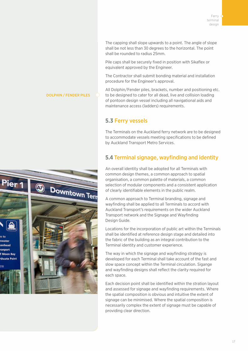
All Dolphin/Fender piles, brackets, number and positioning etc. to be designed to cater for all dead, live and collision loading of pontoon design vessel including all navigational aids and maintenance access (ladders) requirements.
5.3 Ferry vessels
The Terminals on the Auckland ferry network are to be designed to accommodate vessels meeting specifications to be defined by Auckland Transport Metro Services.
5.4 Terminal signage, wayfinding and identity
An overall identity shall be adopted for all Terminals with common design themes, a common approach to spatial organisation, a common palette of materials, a common selection of modular components and a consistent application of clearly identifiable elements in the public realm.
A common approach to Terminal branding, signage and wayfinding shall be applied to all Terminals to accord with Auckland Transport’s requirements on the wider Auckland Transport network and the Signage and Wayfinding Design Guide.
Locations for the incorporation of public art within the Terminals shall be identified at reference design stage and detailed into the fabric of the building as an integral contribution to the Terminal identity and customer experience.
The way in which the signage and wayfinding strategy is developed for each Terminal shall take account of the fast and slow space concept within the Terminal circulation. Sigange and wayfinding designs shall reflect the clarity required for each space.
Each decision point shall be identified within the stration layout and assessed for signage and wayfinding requirements. Where the spatial composition is obvious and intuitive the extent of signage can be minimised. Where the spatial composition is necessarily complex the extent of signage must be capable of providing clear direction.
DOLPHIN / FENDER PILES

TDM | ENGINEERING DESIGN CODE18
5.5 Passenger Information Displays (PIDs) and customer information
Location of PIDs must allow sufficient space to accommodate dwell cones for passengers viewing the information without impacting on passenger routes through the Terminal.
PIDs must not be located above gate-lines, at major thoroughfares where passengers stopping to read the information will block the passenger flow through the space.
Variable real-time information displays and directional signage shall be provided in areas of the Terminal to assist in efficient passenger navigation of the internal spaces under normal, disrupted and emergency incident conditions.
LOCATION
PID location diagram
2.5m
min
imum
platform level
15 15
screen adjustment
15m minimum clear sightlines req.
double sided pid
example support structure
PASSENGER NAVIGATION
Real-time information shall be provided to advise passengers at all key decision locations within the Terminals. This information shall consist of audible PA announcements, variable information displays, paper displays and static non-illuminated and illuminated informative signage. Switchable signage shall be incorporated where passenger management techniques are required to be implemented.
Customer information shall not be located where it will cause obstructions to passenger flows. Specific attention shall be paid to the pause time that passengers need to read the contents of the displays and ensure that these locations do not obstruct the primary flows of passengers though the Terminal spaces. Character heights of all directional signage and customer information displays shall be designed to give legibility of the written text within the viewing cone established for each location. Internationally recognised pictograms shall be used to assist in passenger navigation through the Terminal. All signage shall comply with the AT Signage and Branding Manual guidelines.

19
Ferry terminal
design
5.6 Cycling
Terminal designs shall provide for cycle parking facilities in line with Auckland Transport policy and cycle demand evaluatuion for the Terminal location. All Terminals shall be evaluated for the provision of ‘ebike’ charging facilities as part of the cycle parking provision.
Cycle parking facilities shall be provided in close proximity to Terminal entrances to facilitate cyclists transferring to ferry. Cycle parking areas at Terminals shall, where possible, be located in clearly defined open areas within sight of the Terminal entrance and in clear view of passengers and staff to provide for good passive surveillance. The areas shall be well lit and be included within the Terminal CCTV surveillance system.
The cycle parking shall be supported by associated design features such as signage and lighting to promote their use and should adhere to CPTED principles.
Routes to lifts shall be provided, to take passengers with cycles to platforms. Routes to stairs shall be fitted with cycle wheel channels to permit cyclists to access changes in level.
In assessing the cycle parking needs Terminal entrances ‘e bike’ charging points shall be investigated for inclusion within the design
5.7 Terminal space planning
All passenger routes within Terminals shall be designed to minimise the number of changes of direction, provide clarity of spatial organisation to enable ease of navigation, avoid conflicting flows and provide intuitive wayfinding without reliance upon excessive signage and customer information displays.
All public spaces shall be designed to accommodate the expected passenger volumes in the average minute in the peak fifteen minutes of the peak operating hour not below FRUIN Level of Service C in the design year, 30 years from project completion.
PARKING FACILITIES
DESIGN FEATURES
ROUTES
CHARGING POINTS
Level of service Description Area requirement
for queues m2 person
A Free circulation >1.2
BUni-directional flows and free circulation. Reverse and cross-flows with only minor conflicts
>0.9
CSlightly restricted circulation due to difficulty in passing others. Reverse and cross-flows with difficulty
>0.65
DRestricted circulation for most pedestrians. Significant difficulty for reverse and cross-flows
>0.28
ERestricted circulation for all pedestrians. Intermittent stoppages and serious difficulties for reverse and cross-flows
>0.19
F Complete breakdown in traffic flow with many stoppages <0.19
TDM | ENGINEERING DESIGN CODE20
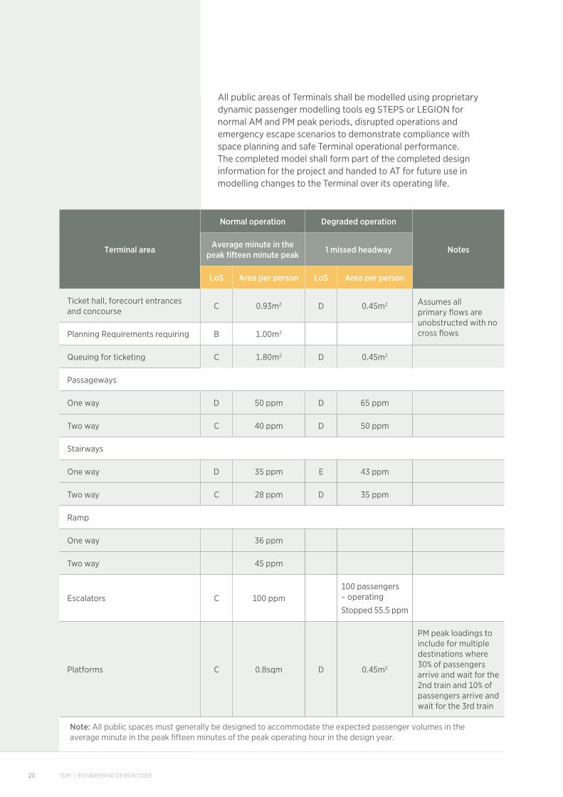
All public areas of Terminals shall be modelled using proprietary dynamic passenger modelling tools eg STEPS or LEGION for normal AM and PM peak periods, disrupted operations and emergency escape scenarios to demonstrate compliance with space planning and safe Terminal operational performance. The completed model shall form part of the completed design information for the project and handed to AT for future use in modelling changes to the Terminal over its operating life.
Terminal area
Normal operation Degraded operation
NotesAverage minute in the peak fifteen minute peak 1 missed headway
LoS Area per person LoS Area per person
Ticket hall, forecourt entrances and concourse
C 0.93m2 D 0.45m2 Assumes all primary flows are unobstructed with no cross flowsPlanning Requirements requiring B 1.00m2
Queuing for ticketing C 1.80m2 D 0.45m2
Passageways
One way D 50 ppm D 65 ppm
Two way C 40 ppm D 50 ppm
Stairways
One way D 35 ppm E 43 ppm
Two way C 28 ppm D 35 ppm
Ramp
One way 36 ppm
Two way 45 ppm
Escalators C 100 ppm100 passengers – operating
Stopped 55.5 ppm
Platforms C 0.8sqm D 0.45m2
PM peak loadings to include for multiple destinations where 30% of passengers arrive and wait for the 2nd train and 10% of passengers arrive and wait for the 3rd train
Note: All public spaces must generally be designed to accommodate the expected passenger volumes in the average minute in the peak fifteen minutes of the peak operating hour in the design year.

21
Ferry terminal
design
Sufficient run-off distances shall be provided to and from lifts, escalators and stairs to enable safe use of vertical circulation and with the appropriate capacity to avoid passenger congestion and conflicting passenger movements.
Element Run off/queuing (Minim requirement)
People per minute PPM Notes
Stair to Ticket gateline 6-10m N/A
Stair to Passageway 4m N/A
Stair at Street - to the back of footpath or other circulation zone (i.e. not obstructing or overlapping into circulation area)
4m N/A
Stair to Escalator 6-10m Not required
Ticket gatelineLoS D 0.45m2 queuing passengers
Ticket gateline at Street 6m Not required
Ticket gateline to platform
The active clear platform area
4m Not requiredA fence between the gate lines and platform where gate lines perpendicular to platform edge
Lift Doors to PassagewayL 4m, W 500mm on either side of doors
Not required
Passenger Information Displays
2m LoS B
10% of 15 minute peakMain information displays in the ticket halls require a queue space equal to the legibility of the board display
Time table board 2m Not required
Public passageways
The clear circulation zone of the passage (i.e. not obstructing or over-lapping into the circulation area
50 ppm LoS C for 1-way flow 40 ppm for 2-way flow Los C
Retail outlets (active edges) 4m
Ticket Vending Machines (dedicated queue zone)
L 4m, W 2m, 1m centers 6 people in queue
1 per minute transaction
Maximum wait time: 3 minutes
Ticket windowsL 4m, windows 2m module, 6 people in queue
2 minutes per transaction
Maximum wait time: 3 minutes
Ticket gateline/ smart readers
L 4m, W 2m, 1m centres
25 people per gate per minute
Assuming redundancy of one gate in each ticket gateline with up to 10 gates, two gates for gate-lines over 10. One wide aisle gate to be provided in every ticket gate line.
Commercial vending machine and public phone
0.9 x 1.2m, L 4m, W 1m, centres 1m between machines
Not required Not required
Automatic Teller Machine (ATM)
L 4m; W 2m (1m CL)6 people in queue
Seating 500mm Offset from passageways
Note: Terminal elements that are not nominated in this table required 0.9 x 1.2m minimum zone measure from active face.
TDM | ENGINEERING DESIGN CODE22
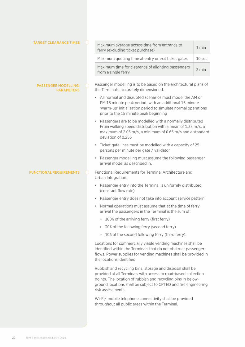
Maximum average access time from entrance to ferry (excluding ticket purchase)
1 min
Maximum queuing time at entry or exit ticket gates 10 sec
Maximum time for clearance of alighting passengers from a single ferry
3 min
Passenger modelling is to be based on the architectural plans of the Terminals, accurately dimensioned.
• All normal and disrupted scenarios must model the AM or PM 15 minute peak period, with an additional 15 minute ‘warm-up’ initialisation period to simulate normal operations prior to the 15 minute peak beginning
• Passengers are to be modelled with a normally distributed Fruin walking speed distribution with a mean of 1.35 m/s, a maximum of 2.05 m/s, a minimum of 0.65 m/s and a standard deviation of 0.255
• Ticket gate lines must be modelled with a capacity of 25 persons per minute per gate / validator
• Passenger modelling must assume the following passenger arrival model as described in.
Functional Requirements for Terminal Architecture and Urban Integration:
• Passenger entry into the Terminal is uniformly distributed (constant flow rate)
• Passenger entry does not take into account service pattern
• Normal operations must assume that at the time of ferry arrival the passengers in the Terminal is the sum of:
o 100% of the arriving ferry (first ferry)
o 30% of the following ferry (second ferry)
o 10% of the second following ferry (third ferry).
Locations for commercially viable vending machines shall be identified within the Terminals that do not obstruct passenger flows. Power supplies for vending machines shall be provided in the locations identified.
Rubbish and recycling bins, storage and disposal shall be provided at all Terminals with access to road-based collection points. The location of rubbish and recycling bins in below-ground locations shall be subject to CPTED and fire engineering risk assessments.
Wi-Fi/ mobile telephone connectivity shall be provided throughout all public areas within the Terminal.
TARGET CLEARANCE TIMES
PASSENGER MODELLING:PARAMETERS
FUNCTIONAL REQUIREMENTS
23
Ferry terminal
design
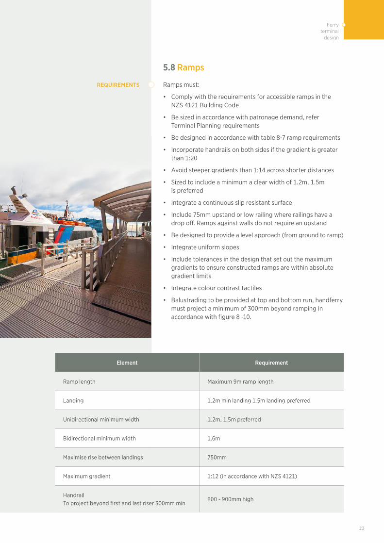
5.8 Ramps
Ramps must:
• Comply with the requirements for accessible ramps in the NZS 4121 Building Code
• Be sized in accordance with patronage demand, refer Terminal Planning requirements
• Be designed in accordance with table 8-7 ramp requirements
• Incorporate handrails on both sides if the gradient is greater than 1:20
• Avoid steeper gradients than 1:14 across shorter distances
• Sized to include a minimum a clear width of 1.2m, 1.5m is preferred
• Integrate a continuous slip resistant surface
• Include 75mm upstand or low railing where railings have a drop off. Ramps against walls do not require an upstand
• Be designed to provide a level approach (from ground to ramp)
• Integrate uniform slopes
• Include tolerances in the design that set out the maximum gradients to ensure constructed ramps are within absolute gradient limits
• Integrate colour contrast tactiles
• Balustrading to be provided at top and bottom run, handferry must project a minimum of 300mm beyond ramping in accordance with figure 8 -10.
REQUIREMENTS
Element Requirement
Ramp length Maximum 9m ramp length
Landing 1.2m min landing 1.5m landing preferred
Unidirectional minimum width 1.2m, 1.5m preferred
Bidirectional minimum width 1.6m
Maximise rise between landings 750mm
Maximum gradient 1:12 (in accordance with NZS 4121)
Handrail To project beyond first and last riser 300mm min
800 - 900mm high

TDM | ENGINEERING DESIGN CODE24
5.9 Design life for terminal components
The design life for Terminal elements shall be in accordance with the typical life expectancies stated here :
Category Envisaged heavy maintenance/part replacement frequency (years)
Design life for design purposes (years)
Public area flooring 15 25
Staff area flooring 10 10
Terminal structural linings system 25 50
Terminal internal secondary wall lining panels 20 30
Terminal internal wall lining system 25 50
Internal partitions 20 50
Staff counters and fittings 10 20
Public toilet fittings 10 20
Public area ceilings 20 30
Staff area ceilings 10 20
Seating 10 20
Balustrading 25 50
External building cladding panels 20 35
Roofing and gutters 25 50
Canopies 25 50
Paving 25 50
Sculpture N/A 50
Signage 10 20
Primary structures 20 100
Secondary structures 20 100
Local ventilation systems 10 20
Electrical wiring 10 20
Air conditioning plant 10 20
Applied coatings 10 20
Floating Pontoons 10 30
Steel Piles N/A 50
Wood Piles N/A 20
Ramps 10 30
Fenders 5 20
Hydraulic systems 10 30
Sullage pumpout system 10 30
Shore Power unit 10 30

25
Ferry terminal
design
Recognized standards shall be used when considering the durability of each component. New, unproven products and finishes are to be avoided unless the design life and performance in use in the location intended is validated by submitted analysis against appearance, performance and cost in use.
Consideration shall be given to the specific environment in which the component and finishes will exist, as well as the monitoring and maintenance works required to maximize the life of the systems and components.
In assessing Terminal components, finishes and fittings for Terminals a whole-of-life costing approach shall be adopted where the optimum balance between initial cost, cost in use and life expectancy is compared against other options before the option choice is made.
Cleaning regimes for finishes shall be determined and recorded during design development to maintain performance and remain within supplier and material specific warrantee conditions.
5.10 Maintainability of terminal elements
All Terminal structures, fittings, components and finishes shall be designed to enable maintenance operations to be carried out safely and efficiently. This shall include anti-graffiti coatings to speed /ease graffiti removal. Maintenance in this context shall be considered to include regular inspections, cleaning, maintenance and replacement. Maintenance shall be capable of being undertaken without interference with normal Terminal operations or else capable of being undertaken wholly within limited non-traffic hours.
Where specialist tools and equipment are required to facilitate maintenance, this equipment is to be identified within the design and local sources for the supply of said equipment identified for use by the Terminal maintainer. Where required, Terminal storage of specialist equipment is to be provided within the Terminal footprint e.g. extending access platforms, gantries and ride on cleaning machines.
The Terminal design shall include a detailed access and maintenance strategy that includes a list of Terminal components, the method of access for cleaning, inspection, repair and replacement, the frequency of carrying out the tasks, the equipment required to carry out the task and the location within the Terminal where the equipment is to be stored.
Installations such as safety anchorages, man-safe systems, walkways, gantries, inclined access ladders, safety chains, lifting beams, access hatches and lifting points shall be designed into the Terminal structure and fabric to give cost-effective access to the highest levels and the deepest pits within the Terminal design.
Where components and finishes are not permanent and will require replacement during the life of the project, they shall be designed to be replaceable in accordance with a corresponding planned safe intervention method developed as part of the design.

TDM | ENGINEERING DESIGN CODE26
An evaluation of the time required for replacement of components and finishes is expected as part of the design process to ensure that the task can be completed within the limited non-traffic hours.
Terminal maintenance activities shall be developed in line with the Terminal Asset Management plan to be developed within the detailed design stage of the project.
The Terminal designs shall be developed in line with the Safety and RAMS Requirement Specification and the Terminal management and Emergency Plan.
5.11Cost-effectiveness of design
All Terminals shall be cost-effective in terms of their Terminal footprint, space planning, three-dimensional form and the choice of elements incorporated into the Terminal fit-out.
Cost-effective design shall be considered in the context of whole-of-life cost, comprising initial constructability and inspection, maintenance, operation and replacement costs (where relevant). Life-cycle cost estimates shall be provided for all key Terminal components and fittings at Product Definition and Reference Design stages of design development.
Common components and modular design of architectural elements shall be embraced within the design to enable high-quality affordable Terminal environments to be created in a consistent way whilst permitting maximum benefits in procurement of identical products for initial construction and ease of replacement during regular maintenance cycles•
5.12 Acoustics
5.12.1 Design principles for accoustic design at terminals
All public areas of the Terminals shall be provided with a public address system to support audible communication from pre-recorded systems and real time announcements from the Terminal control room or the group Terminal control room. The system shall also accommodate audible warnings for fire and life safety purposes in all areas. The acoustic performance of the system shall be designed to give clear audibility to the appropriate RASTI levels at all times in all public areas.
Passengers must be provided with a comfortable environment with respect to acoustics throughout the Terminals at all times during the year. A ‘medium-live’ acoustic impression is preferred in public spaces to avoid excessive noise build-up during busy periods, support PA intelligibility and retain a sense of spaciousness.
All public areas of the Terminals must be provided with a public address system to support audible communication from pre-recorded systems and real time announcements from the Terminal control room or the Terminal group control room.

27
Ferry terminal
design
The system must also accommodate audible warnings for fire and life safety purposes in all areas. The acoustic performance of the system must coordinate space, speaker type/positions and finishes to give clear audibility to the appropriate RASTI levels at all times in all public areas.
Noise levels in Terminals shall be such that customers are able to conduct a conversation without having to shout. All equipment shall be developed and maintained to ensure that noise levels are kept to a minimum.
Passengers shall be provided with a comfortable environment with respect to acoustics throughout the Terminals at all times during the year
The acoustic performance of the system shall coordinate space, speaker type/positions and finishes to give clear audibility to the appropriate RASTI levels at all times in all public areas.
5.12.2 Internal noise level
The unoccupied internal ambient design noise level must not exceed (inclusive of mechanical plant, but excluding contributions from train movements, PA announcements and alarms):
• Ticket sales and customer service centre areas 45 – 50 dB LAeq NA
• Concourse, circulation routes and platform waiting areas 45 – 55 dB LAeq
• Criteria for other relevant industrial, commercial and retail spaces must be determined with reference to Australian/New Zealand Standard AS/NZS 2107:2016.
5.12.3 PA intelligibility
The Public Address (PA) system in ticket sales, concourse and platform areas must be designed as follows:
• Speech Transmission Index (STI): Greater than 0.5. Note STI ranges between 0.0 and 1.0, where 0.0 is completely unintelligible and 1.0 is perfectly intelligible
• Sound Pressure Level (SPL): Capable of 85 dB LAeq and automatic gain control to maintain output 10 decibels above the background noise level (LA95)
• Evenness of coverage: +/-2 decibels using a signal of octave band pink noise centred at 4kHz.
5.12.4 Reverberation time
To support the requirements above, the RT in ticket sales, concourse and platform waiting areas must achieve the ‘medium-live’ design range in the figure below (relative to room volume).
Criteria for other relevant industrial, commercial and retail spaces must be determined with reference to Australian/New Zealand Standard AS/NZS 2107:2016 “Acoustics–Recommended design sound levels and reverberation times for building interiors.

TDM | ENGINEERING DESIGN CODE28
5.12.5 External noise emissions:
Mechanical ventilation plant must not exceed the applicable designation noise limits (refer CRL condition 64 and BTC condition 35).
The acoustic performance of the spaces throughout the Terminal will need detailed consideration in terms of the selection of surface materials / finishes. Areas that must be considered in the acoustic design include but are not limited to:
• Platforms – underground, open-cut and at grade Terminal
• Future-proofing – platform areas for platform screen door inclusion, capacity to change material and cladding.
• Concourse paid and unpaid area
• Terminal forecourts
• Vertical circulation – Escalators, material insulation
• Mechanical plant rooms.
5.13 Security
Terminals shall be designed so as to engender a feeling of safety and security for staff and public moving through all areas. This will create an environment in which passengers and staff feel comfortable and with no perceivable threat to their personal safety, security and wellbeing in line with the requirements set out in the CPTED principles and guidelines. This shall be achieved by establishing the infrastructure such that a practical minimum level of active control and supervision is required to achieve the above security objective.
CCTV security monitoring and recording shall be incorporated within the Terminal design with monitoring from a dedicated security management centre, the group Terminal control room and from the local Terminal control room.
The CCTV surveillance regime shall include turn, tilt and zoom facilities and provide image quality for secure recording and potential use in a court of law.
All rooms used for the handling of cash shall be provided with additional security measures such as panic buttons, intruder detection, anti-bandit laminated glazing and three way locking devices on secure doorways. Where possible the location of ticket issuing machines and cash machines shall be chosen to permit access from a secure room outside of the public domain for cash removal/refilling.
Remote maintenance access points shall be provided with audio/visual links to the Terminal control room and remote release door locks e.g. where access for maintenance is located within shafts remote from the Terminal control room
Electronic key locks shall be provided to doors to frequently accessed principle rooms within Terminal facilities.
Terminal entrances shall be designed to prevent unauthorized access to the ferryway operational area when the Terminal is closed.

29
Ferry terminal
design
Terminal facilities and the immediate precinct outside of Terminal entrances shall be designed from a personal safety and security perspective, lit to a high level and even distribution of illumination using high quality white light sources with good colour rendition, shall avoid obstructions, avoid concealed and difficult to monitor spaces and shall be provided with comprehensive, 100 % coverage of CCTV monitoring from the Terminal control centre.
Staff facilities and active frontages from retail activities within the Terminal shall be used to assist in passive security monitoring in addition to CCTV coverage.
Footpaths adjacent to Terminal entrances/secure accommodation shall be provided with steel bollards at 1500mm centres to prevent vehicles from mounting the kerbs and used to penetrate the building envelope
Further security measures are to be developed within Terminal designs in response to on-going dialogues with NZ Police and security services.
CPTED design principles to be adopted in Terminal designs
• Provide safe movement, good connections and access along paths, changes of direction or changes in height
• Entrances to buildings must be safe and accessible without compromising security
• Sudden or blind corners must be avoided
• Views must not be obscured by obstructions that provide hiding places for offenders
• Pedestrian tunnels/underpasses must have end-to-end visibility
• Surveillance equipment and help points must be clearly visible and identifiable
• High-risk activities must be shifted to high trafficked locations and take advantage of natural surveillance within the safe area
• Reinforce passive surveillance to ensure passengers can see and be seen (for example, glazed lifts)
• Keep columns and other visual obstructions to minimum dimensions.
• Provide consistently placed, high quality lighting which will not conflict with obstructions or create areas of shadow or excessive contrast to lighting levels
• Use white light where possible to enhance face recognition and improved visibility
• Lighting must comply with New Zealand building standards and relevant codes
• Exterior and interior spaces must be evenly lit to allow for surveillance
• Maximise natural light through the use of glazing or transparent materials on elevations and skylights
• Finishes must be utilised to maximise the sense of spaciousness, light and airiness.
Lighting must not distract or interfere with the helm of ferries or other vessels.
ACCESS, MOVEMENT, SIGHTLINESAND NATURAL SURVEILLANCE
LIGHTING
TDM | ENGINEERING DESIGN CODE30
• Public places must encourage social interaction, a mix of uses and allow surveillance so that spaces can be used throughout the day and the evening
• Pedestrian/ cycling routes must be designed to promote use
• Pedestrian routes must run alongside vehicular routes and be visible.
Where buildings are set back from the street the area must be developed to minimise hiding and entrapment spots.
• Routes must be designed along active edges and visible from staff zones where possible.
• Areas accommodating cash transactions must be located in high traffic areas and visible from staff areas
• Natural access is considered, providing clear entry and exit points and a legible, accessible route through the space
• The public must be clearly guided from specific entrances and exits.
• Materials and finishes must be selected based on durability, robustness, high quality and appropriately positioned for routine maintenance and limit incidents of vandalism
• Provide a high quality attractive environment/asset appreciated by users and broader community
• Spaces must be detailed in a manner that deters scaling (climbing).
Consideration must be given to placing higher-quality materials in locations that provide high-quality environments while minimising potential for vandalism.
• Terminal and precinct spaces must provide alternative routes or exits and avoid entrapment
• Signage must warn people of potential entrapment spots and alternative routes.
• Define space ownership to limit vandalism, graffiti and anti-social behaviour
• Avoid creating “left over spaces” for which no-one (public asset or ferry operator) assumes ownership
• Design spaces to accommodate long-term and continued use fit for its purpose. These include forecourt, unpaid concourse, ticket hall and paid concourse areas.
Maintain lighting, landscape, Terminal environment and components to prescribed CRL standards.
• Designs must embody intuitive wayfinding and reduce reliance on signage and visual clutter
• Signs must be developed as a system with a consistent pattern, based on a hierarchy of important messages.
ACTIVE ROUTES PRECINCT
ACTIVE ROUTES –TERMINAL ENVIRONMENT
APPEARANCE
AVOIDING POTENTIALENTRAPMENT SITUATIONS
CLEAR OWNERSHIP
MANAGEMENT & MAINTENANCE
SIGNAGE AND WAYFINDING

31
Ferry terminal
design
5.14 Sustainability
A quadruple bottom line sustainability approach that encompasses Economic, Environmental, Social and Cultural objectives and outcomes shall be adopted for Terminal designs. Consideration of sustainable outcomes for the project shall be an integral part of the Terminal designs which shall be in line with the AT Sustainability Framework.
In support of the over-arching goal ‘Conserve & Enhance the Natural Environment’ within Auckland Transport’s Sustainability Framework, Terminal designs shall minimise their carbon footprint, considering impacts of construction approach, embodied energy of materials and on-going operational energy and water use.
The Terminals shall be designed for resource efficiency, adopting the five principles of designing out waste as detailed by the UK’s Waste Resource Action Programme (WRAP):
• Design for Reuse and Recovery
• Design for Off Site Construction
• Design for Materials Optimisation
• Design for Waste Efficient Procurement and
• Design for Deconstruction and Flexibility.
The Terminal design shall contribute to the overall project target, where applicable, of attaining an “Excellent” rating from Infrastructure Sustainability Council of Australia’s (ISCA) Infrastructure Sustainability (IS) rating tool or a Green Star rating from the New Zealand Green Building Council.
5.15 Constructability
Terminals shall be designed to enable safe construction and maintenance. Maximum use shall be made of offsite pre-fabrication of components, fittings and finishes and the most efficient assembly methods for their installation. Note sufficient space shall be allowed for construction methods within the designated site boundaries to install prefabricated materials and components in close proximity to the operational ferryway. Safe access and maintenance provision shall be made for the whole of life operation of the Terminal that minimises the impact on ferry operations.
Terminal designs shall be developed in the context of delivery in a live operational ferryway environment. Construction methods shall be chosen that minimise the disruption periods to the operating ferryway and that maintain safe operating conditions at all times.
Terminal designs shall adopt a modular approach to common components and where possible utilise components, fittings and finishes that are common across other Terminals on the Auckland ferry network to reduce construction time, ongong maintenance costs and simplify the replacement during the life of the facility.
Structural steel components shall be designed to be prefabricated off site as much as possible so that factory applied coatings can be use.

TDM | ENGINEERING DESIGN CODE32
5.16 Reliability/availability of critical plant and equipment
The design of Terminals shall incorporate the concept of Reliability, Availability, Maintainability and Safety (RAMS). Selection of all systems and system components must consider the service life of all systems, system reliability and resilience, and the installation methods to ensure that the system is suitable for the application, safe and maintainable.
Specification of materials, plant and equipment will be undertaken with a RAMS framework consistent with the application of EN50126
5.17 Designing for safety
Terminals shall be designed taking into account the need to reduce the safety risks of constructing, operating and maintaining Terminals so far as reasonably practical. The design for safety approach shall by adoption of a risk management process:
• Minimise the need for high risk construction or maintenance activities by suitably amending the design where practical
• Incorporate into the design, provisions for safe access for construction, maintenance and replacement (where applicable)
• Reduce the need for maintenance interventions by suitable design and specifications
• Passenger safety in the event of individuals falling off platforms.
The design for safety approach shall include preparation of a risk register at the design stage capable of being used for management of safety by the future constructors and maintainers.
All works shall be designed to comply with the current requirements of relevant New Zealand Legislation for construction, operation and maintenance.
Inclusive but not limited to the NZ Building Code, NZ Standards, Ferryway Act 2005, Health and Safety at Work Act 2015, H&S in Employment Act 1992, H&S in Employment Regulations 1995, and Electricity (Safety) Regulations 2010.
Note: The process of assuring adequate ferryway operational safety for passengers and staff is described elsewhere as it requires a multi-discipline approach covering all disciplines and Terminal elements.
5.18 Storage facilities at terminals
Sufficient storage facilities shall be included at each level within each Terminal to respond to the functional needs of the operating Terminal and the needs of the maintainers.

33
Ferry terminal
design
Typically storage space shall be created in the following locations:
• Customer service centre at entrance/concourse level: for paper and customer care items
• Retail service store, at entrance/concourse level: for stores related to retail activities
• Cleaning store, at a location with ready access to all levels in the Terminal: including provision for charging (ventilation and power), filling and emptying (water and drainage) the electrically powered ride on cleaning machine
• Maintenance access store, at a location with ready access to all levels in the Terminal.
5.19 Detailing
Detailing of Terminal elements shall take into account the robust nature required in marine environments and in elements that are exposed to vandalism in the public domain.
Wall lining panel designs shall take into account resistance to deformation and surface damage due to impact, particularly in the zones below 1.8m from floor level.
Glazed cladding and glazing to stand- alone structures shall be designed to be regularly cleaned without reliance upon unavailable local specialist equipment.
Glazing shall also include vision strips to public doorways and facades of unrelieved glass construction to ensure that the surface remains visible to passengers.
Horizontal ledges and inclined surfaces that are visible to the public shall be avoided unless absolutely necessary within the design as these attract airborne dirt and require frequent cleaning to maintain appearance
5.20 Hazards and risks
Terminals must include a comprehensive cross discipline risk assessment at each stage of design development that meets the Auckland Transport risk management process and must include but is not limited to:
• The safe means of access and space planning for all public and staff areas of the Terminal
• A safe means of access for maintenance equipment, plant and machinery during planned and unplanned maintenance operations with particular attention to Terminal elements that are in close proximity to the operational ferry envelope
• Provide recess-free public spaces and cladding systems and avoid designs that could harbour litter and provide possible hiding places
• The choice of material finishes in all staff and public areas to ensure that risks associated with the operation and maintenance of the Terminal.


