Page 1
ATINER CONFERENCE PAPER SERIES No: LNG2014-1176
1
Athens Institute for Education and Research
ATINER
ATINER's Conference Paper Series
TRA2015-1552
Mihaela Popescu
Professor
University of Craiova
Romania
Alexandra Preda
Assistant
University of Craiova
Romania
Vlad Suru
Lecturer
University of Craiova
Romania
Synchronous Reference Frame
Method Applied in the Indirect Current
Control for Active DC Traction
Substation
Page 2
ATINER CONFERENCE PAPER SERIES No: TRA2015-1552
An Introduction to
ATINER's Conference Paper Series
ATINER started to publish this conference papers series in 2012. It includes only the
papers submitted for publication after they were presented at one of the conferences
organized by our Institute every year. This paper has been peer reviewed by at least two
academic members of ATINER.
Dr. Gregory T. Papanikos
President
Athens Institute for Education and Research
This paper should be cited as follows:
Popescu, M., Preda, A. and Suru, V. (2015). "Synchronous Reference Frame
Method Applied in the Indirect Current Control for Active DC Traction
Substation", Athens: ATINER'S Conference Paper Series,
No: TRA2015-1552.
Athens Institute for Education and Research
8 Valaoritou Street, Kolonaki, 10671 Athens, Greece
Tel: + 30 210 3634210 Fax: + 30 210 3634209 Email: [email protected] URL:
www.atiner.gr
URL Conference Papers Series: www.atiner.gr/papers.htm
Printed in Athens, Greece by the Athens Institute for Education and Research. All rights
reserved. Reproduction is allowed for non-commercial purposes if the source is fully
acknowledged.
ISSN: 2241-2891
09/08/2015
Page 3
ATINER CONFERENCE PAPER SERIES No: TRA2015-1552
3
Synchronous Reference Frame Method Applied in the
Indirect Current Control for Active DC Traction Substation
Mihaela Popescu
Professor
University of Craiova
Romania
Alexandra Preda
Assistant
University of Craiova
Romania
Vlad Suru
Lecturer
University of Craiova
Romania
Abstract
This paper is focused on the increasing the energy efficiency of a DC-
traction substation with 12-pulse parallel diode rectifier, by transforming it into
an active substation, being able to ensure both power quality improvement and
braking energy recovery. A system for active filtering and regeneration, named
SISFREG, is proposed to be connected between the catenary-line and the
primary of the traction transformer, via a dedicated transformer. The main
component of SISFREG is a shunt active power filter based on voltage source
inverter structure, whose control guarantees the keeping of the prescribed
voltage on the DC-side and the proper current at the inverter output by the
indirect control of the supply current. The Synchronous Reference Frame
method is used to generate the sinusoidal reference supply current in phase
with the fundamental of the supply voltage, so that the total compensation
strategy is implemented. Based on the Matlab/Simulink model of the whole
system, the proper operation is confirmed and the good performance of the
system during both filtering and regeneration modes is proven.
Keywords: DC traction, energy recovery, active filtering, indirect current
control, synchronous reference frame.
Acknowledgments: This work was performed through the program
Partnerships in priority areas — PN II, conducted with the financial support of
MEN – UEFISCDI, project no. PN-II-PT-PCCA-2013-4-0564
(42/01.07.2014).
Page 4
ATINER CONFERENCE PAPER SERIES No: TRA2015-1552
4
Introduction
A current concern of the specialists in the field of DC-traction systems is
finding performant solutions for increasing the energy efficiency.
One of the research directions is directed towards improving the power
quality at the input of the traction transformer during the operating in traction
regime through passive and active compensators [1]-[3].
On the other hand, based on the capability of DC-traction motors to
operate in regeneration regime, the reuse of the normally wasted braking
energy is another preoccupation. In addition to the braking energy storage in
on-board or mobile batteries or supercapacitors, the solution of equipping the
existent substations with bidirectional static converters became attractive with
new technological achievements in the field of power semiconductor devices
and their control. For instance, an outcome of RailEnergy cooperative research
program was the HESOP energy recovery system, which is a fully integrated
reversible DC substation for a 750 Vdc application containing a thyristor
rectifier bridge associated with an IGBT converter [4]. By Sitras Thyristor
Controlled Inverter (TCI) to be connected in parallel with the traction
uncontrolled rectifier, the global powerhouse Siemens provides another
solution to acquire the capability to return the braking energy to the system [5].
In the Ingeber solution adopted by the company Ingeteam Traction, a series
connection between a boost DC-DC converter and an inverter is coupled in the
existing traction transformer secondary [6].
In a so-called “active substation”, new functions such as harmonic
filtering, reactive power compensation and voltage regulation may be carried
out in addition to the recovery of braking energy [7].
In order to perform the active filtering function, the control of the
instantaneous active and reactive powers is usually adopted [8]-[10]. In [11],
the generation of the reference current is based on the selective harmonic
extraction method applied to the load current, by using three synchronously
rotating reference frames.
The active DC traction substation, which is the subject of this paper, is
obtained starting from a common traction substation with 12-pulse parallel
uncontrolled rectifier by adding a shunt active power filter (SAPF) based on
structure of voltage source inverter (VSI) between the DC-line and power
supply via a dedicated transformer. At the DC and AC sides of SAPF, passive
circuits for separation and coupling are provided.
The paper is organized as follows. Structure of the System for
Regeneration and Active Filtering Section presents the structure of whole DC
traction system allowing the operation in filtering and regeneration modes.
Reference Current Calculation through the Synchronous Reference Frame
Method Section describes the indirect current control implementation through
the method of synchronous reference frame. Then, after introducing the
Simulink model of the system, the next section presents the model-based
performance in both filtering and regeneration regimes. The paper ends with
the main conclusions.
Page 5
ATINER CONFERENCE PAPER SERIES No: TRA2015-1552
5
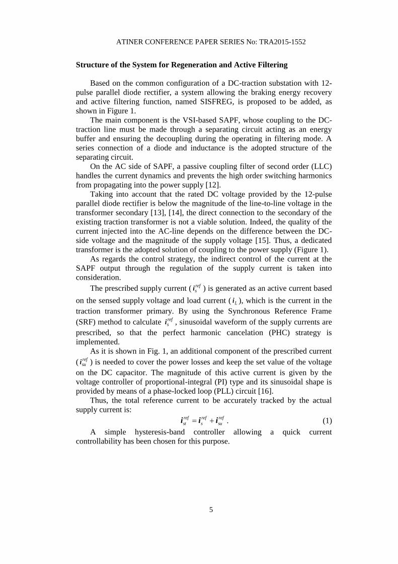
Structure of the System for Regeneration and Active Filtering
Based on the common configuration of a DC-traction substation with 12-
pulse parallel diode rectifier, a system allowing the braking energy recovery
and active filtering function, named SISFREG, is proposed to be added, as
shown in Figure 1.
The main component is the VSI-based SAPF, whose coupling to the DC-
traction line must be made through a separating circuit acting as an energy
buffer and ensuring the decoupling during the operating in filtering mode. A
series connection of a diode and inductance is the adopted structure of the
separating circuit.
On the AC side of SAPF, a passive coupling filter of second order (LLC)
handles the current dynamics and prevents the high order switching harmonics
from propagating into the power supply [12].
Taking into account that the rated DC voltage provided by the 12-pulse
parallel diode rectifier is below the magnitude of the line-to-line voltage in the
transformer secondary [13], [14], the direct connection to the secondary of the
existing traction transformer is not a viable solution. Indeed, the quality of the
current injected into the AC-line depends on the difference between the DC-
side voltage and the magnitude of the supply voltage [15]. Thus, a dedicated
transformer is the adopted solution of coupling to the power supply (Figure 1).
As regards the control strategy, the indirect control of the current at the
SAPF output through the regulation of the supply current is taken into
consideration.
The prescribed supply current ( refsi ) is generated as an active current based
on the sensed supply voltage and load current ( Li ), which is the current in the
traction transformer primary. By using the Synchronous Reference Frame
(SRF) method to calculate refsi , sinusoidal waveform of the supply currents are
prescribed, so that the perfect harmonic cancelation (PHC) strategy is
implemented.
As it is shown in Fig. 1, an additional component of the prescribed current
( refsui ) is needed to cover the power losses and keep the set value of the voltage
on the DC capacitor. The magnitude of this active current is given by the
voltage controller of proportional-integral (PI) type and its sinusoidal shape is
provided by means of a phase-locked loop (PLL) circuit [16].
Thus, the total reference current to be accurately tracked by the actual
supply current is:
ref
su
ref
s
ref
st iii . (1)
A simple hysteresis-band controller allowing a quick current
controllability has been chosen for this purpose.
Page 6
ATINER CONFERENCE PAPER SERIES No: TRA2015-1552
6
Figure 1. Block Diagram of the Proposed Active DC Traction Substation
been chosen for this purpose.
Reference Current Calculation through the Synchronous Reference
Frame Method
The flexibility of the synchronous reference frame (SRF) theory in
separating the harmonic components of a distorted signal made this method to
be widely used in the control of SAPF [17]-[20]. The principle is based on the
fact that the harmonics frequency changes in a rotating reference frame, so that
the fundamental and harmonic components can be isolated with low and high
pass filters.
The transformation of the load current from the phase coordinate system
(a, b, c) to the rotating orthogonal reference frame (d, q) having the d-axis
aligned with the voltage space phasor is performed in two stages.
First, the Clarke transform modifies the three-phase system to the
stationary two-phase orthogonal frame (α, β),
Lc
Lb
La
L
L
i
i
i
i
i
31310
313132
. (2)
Then, the forward Park transformation allows passing the current
components from the stationary (α, β) frame to the synchronous (d, q) frame,
L
L
Lq
Ld
i
i
i
i
cossin
sincos, (3)
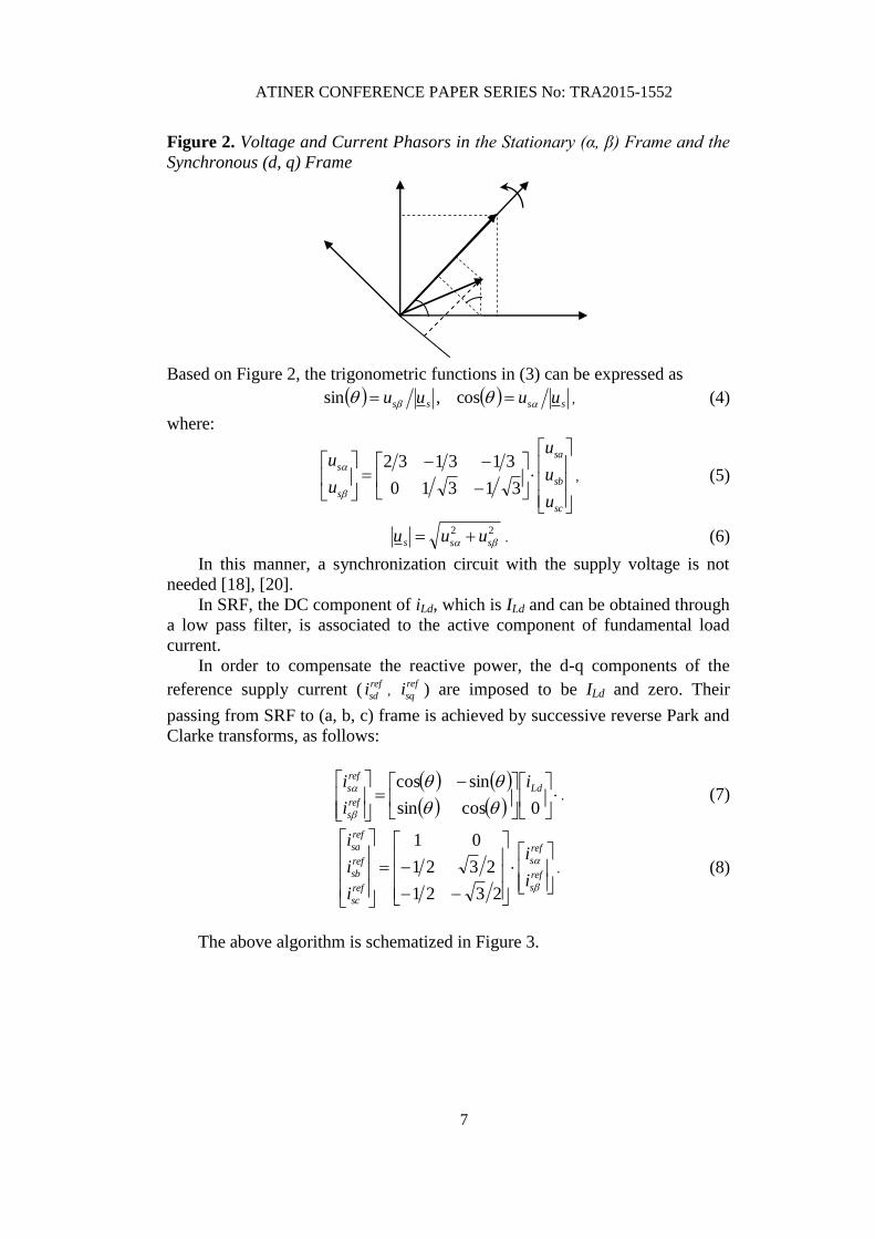
where θ is the position angle of the rotating axis d (the voltage phasor angle)
(Figure 2).
SIS
FREG
Gating
signals Voltage
control
Reference
current
calculation
S
APF
Traction
transformer 12-pulse parallel
diode rectifier
Dedicated
transformer Separating
circuit
+
-
C
u
s, is
u
C
DC-
traction
line
DC-traction
substation
i
F
P
CC i
L
u
s
Interface
filter
u
DC
x
PLL
u
s
i
L
i
s
+
+ Current
control
refsi
refsui
refsti
refCu
Page 7
ATINER CONFERENCE PAPER SERIES No: TRA2015-1552
7
Figure 2. Voltage and Current Phasors in the Stationary (α, β) Frame and the
Synchronous (d, q) Frame
Based on Figure 2, the trigonometric functions in (3) can be expressed as
ssss uuuu cos,sin , (4)
where:
sc
sb
sa
s
s
u
u
u
u
u
31310
313132
, (5)
22
sss uuu . (6)
In this manner, a synchronization circuit with the supply voltage is not
needed [18], [20].
In SRF, the DC component of iLd, which is ILd and can be obtained through
a low pass filter, is associated to the active component of fundamental load
current.
In order to compensate the reactive power, the d-q components of the
reference supply current ( ref
sdi , ref
sqi ) are imposed to be ILd and zero. Their
passing from SRF to (a, b, c) frame is achieved by successive reverse Park and
Clarke transforms, as follows:
0cossin
sincos Ld
ref
s
ref
s i
i
i
. (7)
ref
s
ref
s
ref
sc
ref
sb
ref
sa
i
i
i
i
i
2321
2321
01
. (8)
The above algorithm is schematized in Figure 3.
i
L
u
s
α
β
q
d
i
Ld
u
s
u
s
i
Lq
O
Page 8
ATINER CONFERENCE PAPER SERIES No: TRA2015-1552
8
Figure 3. Block Diagram of the Reference Current Calculation
Simulink Model
A specific Matlab/Simulink model of the whole active DC-traction
substation has been created in order to verify the correctness of the proposed
solution and to assess its performance during the filtering and regeneration
regimes (Figure 4).
As shown, in the model of 12-pulse parallel rectifier DC-traction (Figure
5), the Y/y/d traction transformer of rated power of 3.2 MVA provides 1.2 kV
in each secondary to supply the two uncontrolled bridge rectifiers. Two reverse
magnetically coupled inductances are used for the parallel connection of the
rectifiers.
The DC traction line was modeled taking into account that, in traction
regime, it is an active load with a back electromotive force corresponding to
the operation speed, an equivalent resistance and an equivalent inductance.
During the regeneration, the maximal DC-line voltage is maintained and a
constant acceleration is imposed, so that the DC-line current is constant.
A recovery transformer of connection Y/y, 2.2 MVA and 820 V/ 33 kV is
used.
On the DC-side, the compensating capacitor of 100 mF is coupled with the
DC-line by means of the separating circuit consisting of a diode and an
inductance of 40 H.
(a, b, c)
(α-β)
Expr. (2)
i
La i
Lb i
Lc
u
sa
u
sb u
sc
i
L i
L
u
s
u
s
(α-β)
(d-q)
Expr. (3)
(α-β)
(a, b, c)
Expr. (8) (a, b, c)
(α-β)
Expr. (5)
Low
pass
filter
ref
sai
ref
sbi
ref
sci
ref
si
ref
si Trigono-
metric
functions
Expr. (4)
cos
sin
i
Ld
i
Lq
0
I
Ld
(d-q)
(α-β)
Expr. (7)
Page 9
ATINER CONFERENCE PAPER SERIES No: TRA2015-1552
9
Figure 4. Simulink Model of the Active DC Traction Substation
Figure 5. Simulink Model of the DC Traction Substation with 12-Pulse
Parallel Rectifier
The control block of the three-phase three-wire system receives two of the
generated reference currents, actual supply currents, line-to-line voltages in the
transformer primary, together with the DC-capacitor voltage.
The parameters of the PI voltage controller are Kp=30.60 and Ti=3.947·10-
4 s. The hysteresis band imposed for the current controller is 0.5 A.
Page 10
ATINER CONFERENCE PAPER SERIES No: TRA2015-1552
10
The initial charging of the compensating capacitor through a limiting
resistor and contactor K1 is taken into consideration. After the generation of the
total reference currents, including the components needed to keep the DC-
voltage at the prescribed value, the three-phase hysteresis band controller gives
the gating signals for IGBTs.
Different blocks are added in the Simulink model to assess the
performance of the system for filtering and regeneration.
Simulation Results
The operation of the proposed active traction substation has been
simulated for both filtering and regeneration regimes.
First, till t=0.5 s, the system is in traction mode and a distorted current of
THD=12% is drawn in the traction transformer primary (Figure 6). The global
power factor (PF) is of about 0.988.
Figure 6. Phase Voltages and Currents in the Traction Transformer Primary
without Compensation
During this regime, SISFREG operates as an active power filter (Figure 7),
by compensating the current harmonics and the reactive power, so that the
supply current becomes almost sinusoidal (THD2.8%) and in phase with the
voltage (PF0.999). The rms supply current has a small increase, from 57.65 A
to 57.75 A in order to cover the power losses and keep the DC capacitor
voltage at the prescribed value of 1782 V.
From t=0.5 s to t=0.8 s, the operation in regeneration mode is required, the
traction rectifier being blocked. During this regime, a constant acceleration of 2
m/s2 is imposed, leading to a constant DC current (about 2000 A). The AC
current injected to the power supply has a low THD (about 2.7%). As shown in
Figure 8, the supply current is 180 degree out of phase with the AC voltage.
The recovery efficiency, from the catenary line to the AC-line is of about 0.95.
usabc
(V)
Time (s)
u
sa
u
sb
u
sc i
La
i
Lb
i
Lc
i Labc
(A)
Page 11
ATINER CONFERENCE PAPER SERIES No: TRA2015-1552
11
Figure 7. Phase Voltage and Current in the Traction Transformer Primary
Before and After Compensation
Figure 8. Phase Voltage and Current during Regeneration
At t=0.8 s, no regeneration current is needed and the SISFREG passes
again in filtering mode.
The waveform in Figure 9 shows the evolution of the voltages on the DC-
side during the whole simulation period. First, the DC-capacitor is charging
naturally through the APF’s diodes. Then, through a ramp prescription, the set
value of 1782 V is reached with a very low overshoot of about 0.5%. Withal,
the average catenary-line voltage has the rated value of 1500 V.
In regeneration mode, the catenary-line voltage increases and exceeds for a
short time the prescribed value of 1800 V by about 2.5%. The DC-capacitor
remains at its prescribed value which is below catenary-line voltage. During
the system transition to the filtering regime, the catenary-line voltage reaches
the average value of 1500 V with an overshot of about 18%.
Is it can be seen in Figure 10, when the system passes from an operating
mode to the other, a half-period of 10 ms is sufficient to change the sense of
power flow.
The correctness of the system operation is highlighted also by the
waveforms of traction transformer and recovery transformer currents in the
point of common coupling (Figure 11).
It can be seen that the recovery transformer injects either the compensating
current or the regenerated current, whereas the traction transformer current
exists only during the traction regime.
usa
(V
)
Time (s)
u
sa
i
La
i
sa
i La, i sa
(A)
usa
(V
)
Time (s)
i sa
(A)
u
sa i
sa
Page 12
ATINER CONFERENCE PAPER SERIES No: TRA2015-1552
12
Figure 9. Waveforms of the Prescribed (in Magenta) and Actual (in Black)
Voltage across the DC-Capacitor Voltage and the DC-Line Voltage (in Blue)
Figure 10. Phase Voltage and Supply Current when the System Passes from
the Filtering to Regeneration Regime (a) and Vice Versa (b)
Figure 11. Current in the Primary of Traction Transformer (in Black) and
Current in the Secondary of Recovery Transformer (in Blue)
Conclusions
In the proposed structure of the system for converting a DC-traction
substation with 12-pulse parallel diode rectifier into an active substation,
Time (s)
DC
vo
ltag
es
(V)
usa
(V
)
Time (s)
u
sa i
sa
Time (s)
(a)
(b)
usa
(V
)
u
sa
i sa
(A) i
sa
i sa
(A)
i La,
i Fa
(A)
Time (s)
i
Fa
i
La
Page 13
ATINER CONFERENCE PAPER SERIES No: TRA2015-1552
13
besides the SAPF, a dedicated transformer on the AC-side and a separating
circuit on the DC-side are needed.
In the adopted implementation, the indirect current control involves the
generation of the prescribed supply current based on the sensed voltages and
currents in the traction transformer primary by using the SRF method. The
control scheme, with a PI controller to keep the set DC-side voltage and a
hysteresis controller to track the set supply currents, allows obtaining nearly
sinusoidal supply currents and unity power factor in both filtering and
regeneration regimes.
Further research is intended to develop and implement the control
algorithm on an experimental platform based on dSPACE control board.
References
[1] Lao, K. W., Dai, N., Liu, W. G., and Wong, M. C. 2013. Hybrid power quality
compensator with minimum dc operation voltage design for high-speed traction
power systems. IEEE Trans. Power Electron. 28, 4 (April 2013), 2024-2036.
[2] Bahrani, B. and Rufer, A. 2013. Optimization-based voltage support in traction
networks using active line-side converters. IEEE Trans. Power Electron. 28, 2
(Feb. 2013), 673–685.
[3] Shishime, K. 2012. Practical applications of the railway static power conditioner
(RPC) for conventional railways. MEIDEN Review. 3, 156, 38-41.
[4] Cornic D. 2010. Efficient recovery of braking energy through a reversible dc
substation. In Proceedings of the Electrical Systems for Aircraft, Railway and
Ship Propulsion (Bologna, Italy, Oct. 19-21, 2010). ESARS '2010.
[5] Siemens. 2010. Sitras TCI–Thyristor controlled inverter for DC traction power
supply. Siemens AG 2010, https://w3.usa.siemens.com/mobility/us/Documents/
en/rail-solutions/railway-electrification/dc-traction-power-supply/sitras-tci-en.pdf
[6] Ortega, J. M., Ibaiondo, H. and Romo, A. 2011. Kinetic energy recovery on
railway systems with feedback to the grid. In Proceedings of the 9th World
Congress on Railway Research (Lille, France, May 22-26, 2011).WCRR '2011.
[7] Warin, Y., Lanselle, R., and Thiounn M. 2011. Active substation. In Proceedings
of the 9th World Congress on Railway Research (Lille, France, May 22-26,
2011). WCRR '2011.
[8] Bueno, A., Aller, J. M., Restrepo, J., and Habetler, T. 2010. Harmonic and balance
compensation using instantaneous active and reactive power control on electric
railway systems. In Proc. Appl. Power Electron. Conf. Expo. (Palm Springs, CA,
Feb. 21-25, 2010), 1139 -1144. APEC '2010
[9] Ramos, G., Cantor, E., Rios, M. A., and Roa, L. F. 2011. Instantaneous p-q theory
for harmonic compensation with active power filter in dc traction systems. In
Proceedings of International Conference on Power Engineering, Energy and
Electrical Drives (Malaga, Spain, May 11-13, 2011). POWERENG '2011.
[10] Bitoleanu, A. and Popescu, M. 2011. How can the IRP p-q theory be applied for
active filtering under nonsinusoidal voltage operation? Przegląd
Elektrotechniczny, 87, 1, 67-71.
[11] Terciyanli, A., Acik, A., Cetin, A., Ermis, M., Cadirci, I., Ermis, C., Demirci, T.,
and Bilgin, H.F. 2012. Power quality solutions for light rail public transportation
Page 14
ATINER CONFERENCE PAPER SERIES No: TRA2015-1552
14
systems fed by medium-voltage underground cables. IEEE Trans. Ind. Appl., 48,
3 (May/June 2012), 1017-1029.
[12] Bitoleanu, A., Popescu, M., Marin, D., and Dobriceanu, M. 2010. LCL interface
filter design for shunt active power filters. Advances in Electrical and Computer
Engineering, 10, 3 (Aug. 2010), 55-60.
[13] Bitoleanu, A., Mihai, D., Popescu, M., and Constantinescu, C. 2000. Convertoare
statice si structuri de comanda performante. Sitech, Craiova, 2000.
[14] Popescu, M., Bitoleanu, A., Suru, V., and Preda, A. 2015. System for converting
the dc traction substations into active substations. In Proc. International
Symposium on Advanced Topics in Electrical Engineering (Bucharest, Romania,
May 7-9, 2015). ATEE '2015.
[15]Bitoleanu, A. and Popescu, M. 2010. Filtre active de putere. Universitaria
Craiova, 2010.
[16] Popescu, M., Bitoleanu, A., and Suru, V. 2013. A DSP-based implementation of
the p-q theory in active power filtering under nonideal voltage conditions. IEEE
Transactions on Industrial Informatics, 9, 2 (May 2013), 880-889.
[17] Bhattacharya, S. and Divan D. 1995. Synchronous frame based controller
implementation for a hybrid series active filter system. In Proc. 30th Industry
Applications Society Annual Meeting (Orlando, FL, Oct. 8-12, 1995), 2531-2540.
IAS '95.
[18] Soares, V., Verdelho, P., and Marques, G. D. 2000. An instantaneous active and
reactive current component method for active filters. IEEE Trans. Power
Electron., 15, 4 (Jul. 2000), 660-669.
[19] Bhattacharjee, K. 2013. Design and simulation of synchronous reference frame
based shunt active power filter using SIMULINK. In Proc. Conference on
Challenges in Research & Technology in the Coming Decades (Ujire, India, Sept.
27-28, 2013). CRT '2013.
[20]Popescu, M., Dobriceanu, M., Linca, M., and Oprea, G. 2014. Orthogonal
reference frame based methods in three-wire active power line conditioners:
Practical evaluation under unbalanced load and nonideal voltage conditions. In
Proc. International Conference on Optimization of Electrical and Electronic
Equipment (Brasov, Romania, May 22-24, 2014), OPTIM '2014.