ATING RE E VISION AND ANIPULATION Billibon H. Yoshimi and Peter K. Allen Department of Computer Science, Columbia University, New York, NY 10027 * Abstract We describe a system that integrates real-time com- puter vision with a sensorless gripper to provide closed loop feedback control for grasping and manipulation tasks. Many hand-eye coordination skills can be thought of as sensory-control loops, where specialized reasoning has been embodied as a feedback or control path in the loop’s construction. Our framework cap- tures the essence of these hand-eye coordination skills in simple visual control primitives, which are a key component of the software integration. The primitives use a simple visual tracking and correspondence scheme to provide real-time feedback control in the presence of imprecise camera calibrations. Experimental results are shown for the positioning task of locating, picking up, and inserting a bolt into a nut under visual con- trol. Results are also presented for the visual control of a bolt tightening task. 1 Introduction In most manufacturing tasks, it is necessary to have the ability to move parts together in useful configura- tions to make an assembly process more efficient. For example, we might require a robot to grasp a part off the assembly line and insert it into some fixture. In order to perform the grasping portion of this task, the robot must be able to locate the part, move its grip- per to the vicinity of the part, locate the best grasping points to grasp the part, move the fingers of the grip- per to those grasping points, and finally, verify that the grasp is sufficient for holding the part. Usually these kinds of tasks are performed by blind robots which use fixed world coordinates, jigs and other devices to remove the need for the robot to recover where the objects are located. Systems built using this kind of robot control usually require large start-up costs in pre- production measurement, setup and testing. These systems also exhibit inflexible, brittle qualities. If a small design change is made in how the product is man- ufactured, the cost of replanning the robot assembly line which may include extensive retooling and rejig- ging and a total revision of the robot control strat- egy can be prohibitively expensive. The focus of the research described in this paper is to create a hard- ware/software framework for integrating sensing and actuation in real-time for the task of vision-based robot control. We will describe new ways in which vision can be integrated with a robotic task to give the robot the necessary compliance to perform in cases where the robot has little preconceived knowledge about the envi- ronment or the objects to be acted upon. It also serves to highlight how intelligent control can be made more robust by building well understood low-level modules that can then be combined at higher levels to achieve more complex tasks. In particular, we will concentrate on three parts of a bolt grasping and tightening task: how to move the gripper to the vicinity of the bolt, how we can use vision to move the fingers to grasp the bolt, and how we can use vision to monitor the bolt tighten- ing task. We will show that visual feedback gives many systems the compliance necessary to perform the task and the ability to gauge its performance. Other researchers have built systems that use vision to control robot motion. Hollingshurst and Cipolla [5] have developed a system for positioning a gripper above an object in the environment using an affine stereo transform to estimate the object’s position. They correct for the transform’s errors by using a sec- ond control scheme which converts the relative error in image space into a real world positioning change. Cas- tan0 and Hutchinson [Z] use visual constraint planes to create compliant surfaces for constraint robot move- ment in the real world. Both Hager et al. [4] and Fed- dema et al. [3] have used Image Jacobian-based control to perform various positioning tasks. Sharma et al. [SI use perceptual 3D surfaces to represent the workspace of the gripper and object and they plan their position- ing tasks along these surfaces. Other systems which have used visual control include [lo, 7, 6, 9, 13, 11. *This work was supported in part by DARPA contract DACA-76-92-C-0007, an ONR MURI Grant, NSF grants CDA- 90-24735 and IRI-93-11877, and Toshiba Corporation 1060-3425/97 $10.00 0 1997 IEEE 178
Transcript
ATING RE E VISION AND ANIPULATION
Billibon H. Yoshimi and Peter K. Allen Department of Computer Science, Columbia University, New York, NY 10027 *
Abstract We describe a system that integrates real-time com-
puter vision with a sensorless gripper t o provide closed loop feedback control f o r grasping and manipulation tasks. Many hand-eye coordination skills can be thought of as sensory-control loops, where specialized reasoning has been embodied as a feedback or control path in the loop’s construction. Our framework cap- tures the essence of these hand-eye coordination skills in simple visual control primitives, which are a key component of the software integration. The primitives use a simple visual tracking and correspondence scheme to provide real-time feedback control in the presence of imprecise camera calibrations. Experimental results are shown for the positioning task of locating, picking up, and inserting a bolt into a nut under visual con- trol. Results are also presented for the visual control of a bolt tightening task.
1 Introduction
In most manufacturing tasks, it is necessary to have the ability to move parts together in useful configura- tions to make an assembly process more efficient. For example, we might require a robot to grasp a part off the assembly line and insert it into some fixture. In order to perform the grasping portion of this task, the robot must be able to locate the part, move its grip- per to the vicinity of the part, locate the best grasping points to grasp the part, move the fingers of the grip- per to those grasping points, and finally, verify that the grasp is sufficient for holding the part. Usually these kinds of tasks are performed by blind robots which use fixed world coordinates, jigs and other devices to remove the need for the robot to recover where the objects are located. Systems built using this kind of robot control usually require large start-up costs in pre- production measurement, setup and testing. These
systems also exhibit inflexible, brittle qualities. If a small design change is made in how the product is man- ufactured, the cost of replanning the robot assembly line which may include extensive retooling and rejig- ging and a total revision of the robot control strat- egy can be prohibitively expensive. The focus of the research described in this paper is to create a hard- ware/software framework for integrating sensing and actuation in real-time for the task of vision-based robot control. We will describe new ways in which vision can be integrated with a robotic task to give the robot the necessary compliance to perform in cases where the robot has little preconceived knowledge about the envi- ronment or the objects to be acted upon. It also serves to highlight how intelligent control can be made more robust by building well understood low-level modules that can then be combined at higher levels to achieve more complex tasks. In particular, we will concentrate on three parts of a bolt grasping and tightening task: how to move the gripper to the vicinity of the bolt, how we can use vision to move the fingers to grasp the bolt, and how we can use vision to monitor the bolt tighten- ing task. We will show that visual feedback gives many systems the compliance necessary to perform the task and the ability to gauge its performance.
Other researchers have built systems that use vision to control robot motion. Hollingshurst and Cipolla [5] have developed a system for positioning a gripper above an object in the environment using an affine stereo transform to estimate the object’s position. They correct for the transform’s errors by using a sec- ond control scheme which converts the relative error in image space into a real world positioning change. Cas- tan0 and Hutchinson [Z] use visual constraint planes to create compliant surfaces for constraint robot move- ment in the real world. Both Hager et al. [4] and Fed- dema et al. [3] have used Image Jacobian-based control to perform various positioning tasks. Sharma et al. [SI use perceptual 3D surfaces to represent the workspace of the gripper and object and they plan their position- ing tasks along these surfaces. Other systems which have used visual control include [lo, 7, 6, 9, 13, 11.
*This work was supported in part by DARPA contract DACA-76-92-C-0007, an ONR MURI Grant, NSF grants CDA- 90-24735 and IRI-93-11877, and Toshiba Corporation
1060-3425/97 $10.00 0 1997 IEEE 178
Puma and Gripper
Bolt /--7--.
Stereo Cameras
There are three problems with the gri ppcr which make it difficult to use. First,, the gripper systcrri is totally devoid of sensors. This is a common problcrri shared by many other grippers. The variation in a fin- ger’s dimensions a s it changes positions makes it very difficult to attach sensors to the fingers. One mcthod which can be used to overcome this problem is the USC
of external sensors to provide feedback for closed loop control. We use vision to control the positioning of the gripper’s fingers and to estimate when they have made contact with other objects in the environment. Second, the control space of the fingers is non-linear. Changes in pressure to a chamber do not necessary correspond to a equivalent linear change in finger position. In a later section, we will describe how we used visual con- trol to compensate for this problem. And finally, we need to compensate for minor occlusions, a problem common in most grasping and finger-scale manipula- tions. To solve this problem, we have added additional structures to each fingers to move the fiducial marks as- sociated with that finger to positions where they were not occluded by the object.
Figure 1: Experimental system used to test visual con- trol of grasping and manipulation.
3 Object tracking algorithm
Our system is specifically aimed a t merging vision with grasping by providing visual control of position and contact using sensorless robotic fingers and hands. De- tails on this research can be found in [12].
2 Experimental system
The system pictured in figure 1 shows the major components of the system: a robot, a gripper, and two fixed stereo cameras. The gripper we used is a Toshiba FMA gripper (see figure 3). The gripper is comprised of 4 fingers where each finger is made up of 3 stretchable, flexible chambers [ll]. The gripper could be positioned in a variety of different poses by changing the pressure in each of the finger chambers. The original design used binary pressure valves which limited the movement of each finger to only eight possi- ble configurations in a 3 degrees of freedom workspace. In order to perform precise manipulation, we needed greater finger positioning flexibility. We removed the eight position constraint from two fingers by adding 6 continuous pneumatic servo valves. Each valve took an input voltage and converted it into a pressure output. By changing the voltage, we could change the pressure inside each finger chamber. These voltages were gener- ated by a D/A board attached to the central computer.
In order to quickly develop a working experimental system, and thus gain a better understanding of the limits of integrating vision and control, we demanded that the vision system fulfill two requirements. First, it must have the capability of tracking multiple oh- jects. For our experiments, it was necessary to track the position of the gripper, its pose, and the positions of other objects in the environment. And second, the position information should arrive at a high rate with as little delay as possible. Real time control requires low latency.
The vision system we have developed satisfies these constraints. We are able to track multiple moving tar- gets at real time rates. In our system, each moving target is a fiducial mark (a black dot on a white hack- ground) which can be attached to a robot or other objects in the environment. The upper bound of the number of targets trackable a t any one time is 255. Each finger of the robotic hand has 4 fiducial marks, and each object to be manipulated also has 1 or 2 fidu- cial marks. The tracker uses intensity thresholds to segment the fiducial marks from the background. We have implemented the algorithm below on a PIPE par- allel image processing system.
1. A camera images the scene and the image is sent. to the processing stages in the PIPE image processor.
179
2.
3.
4.
5.
The image used for tracking contains uniquely numbered regions which correspond to the posi- tions where the fiducial marks can be found. At the start of an experiment, the operator selects the positions of the fiducial marks to be tracked in an intensity image. These positions are used to seed an morphological region growing process which identifies all of the pixels surrounding the seed which satisfy the fiducial mark’s intensity con- straint. Those pixels which correspond to parts of the same fiducial mark are grouped together, given a unique number, and the region containing their positions noted in the tracking image. The tracking image contains zeros at all other loca- tions. During subsequent iterations, the tracking image is updated by step 5 of the algorithm.
Each fiducial mark region in tracking image is morphologically expanded by 2 pixels. This pro- cess is built into the PIPE processor. The entire process takes 2 frame cycles or (1/30th of a sec- ond) to perform.
The algorithm uses the expanded regions in the tracking image as a template for finding fiducial marks in the intensity image. The fiducial mark intensity constraints associated with each region in the tracking image are applied to the new in- tensity image. If a position satisfies the intensity constraint for a region, it is added to that region, otherwise, it is deleted. The resulting tracking image contains regions which reflect the new ob- served positions of the fiducial marks. The track- ing image is then rewritten to the buffer described in step 2. This step takes 1/60th of a second.
The tracking image is also passed through a his- togram/accumulator processor. The PIPE pro- cessor accumulates the statistics necessary for de- termining the centroid of each uniquely numbered region in the tracking image. This processes also takes 1/60th of a second. This process is per- formed in parallel for both horizontal and vertical camera coordinates and for both cameras. The to- tal delay in finding the centroid positions for a set fiducial marks in both cameras is 116.7 ms.
A set of assumptions make the fiducial mark track- ing tractable. We assume the fiducial marks are al- ways visible, that they are velocity-limited in image space, and that they do not overlap. While systems exist which are not hampered by these restrictions, these constraints may be reasonable for some con- trolled industrial settings where grasping and manip- ulation tasks take place. The current version of the
Figure 2: TOP IMAGE: Initial position of gripper and robot. BOTTOM IMAGE: Gripper and robot position after finishing the approach task. In both images, the x axis points into the image.
algorithm allowed us to perform stereo tracking of 12 features at approximately 15 Hz with an inherent pro- cessing delay of 116.7 ms. (NOTE: Not all features were used in all primitive operations.)
Once a feature has been identified in each camera,
we used stereo back-projection to determine its 3D position in space. The accuracy of this procedure is highly dependent on the accuracy of the camera cal- ibrations. In our system, we perform a simple least squares calibration on each camera. Correspondence between features in each camera is determined initially by the user and the tracking maintains these correspon- dences at each sample interval.
180
4 Move-to-3D-position Primitive
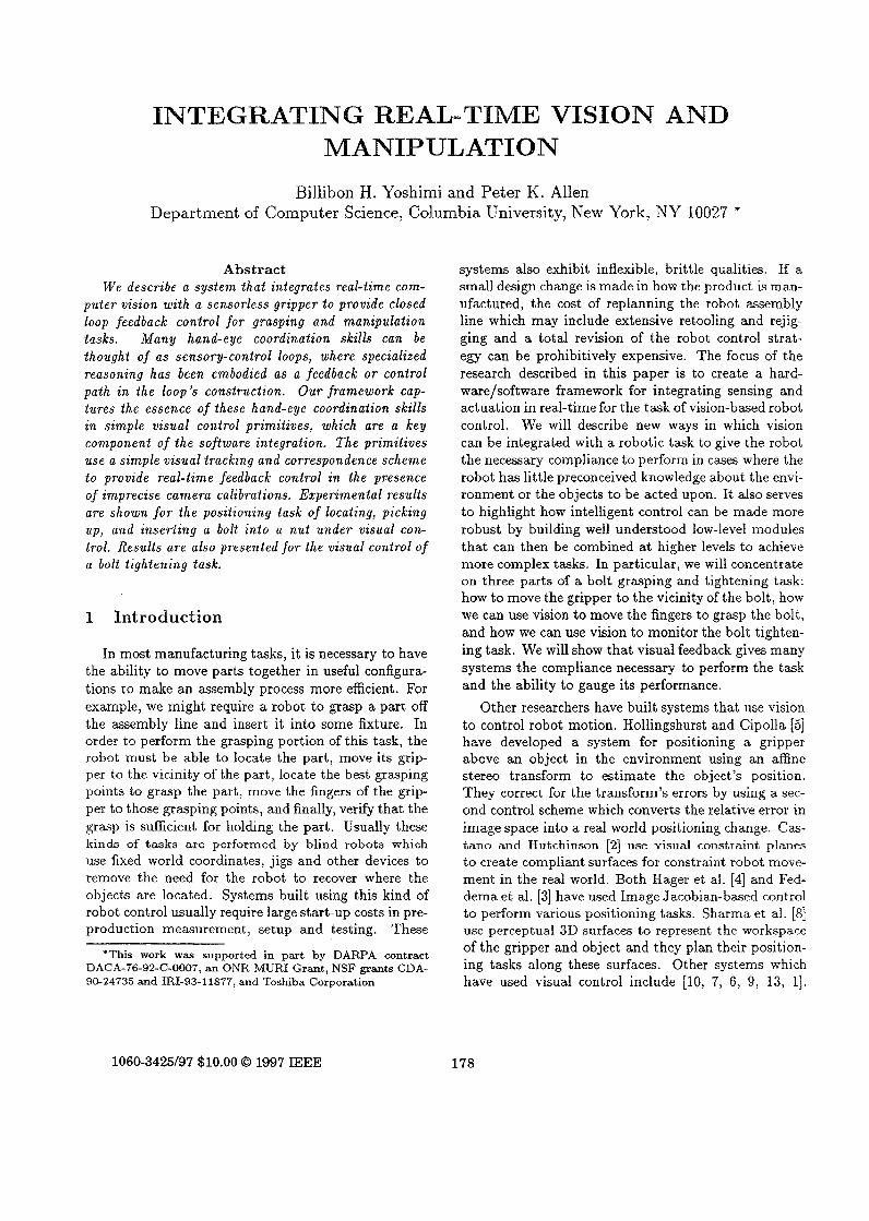
Figure 3: TOP IMAGE: Initial position of gripper and robot. BOTTOM IMAGE: Gripper and robot position after finishing the insert task. In both images, the x axis points into the image.
~
181
- I - I e‘= P2 - P 1
The basic problem in visual control is to relate an image space signal to a corresponding control move- ment. In our case, the robot’s position in the real world, W , is known and controlled by us. What is unknown is the relationship between the position error observed by the vision system and the corresponding control movement in W . In our system, we compute the error in position between a known point on the robot, P 1 , and a goal point in the workspace, P 2 , as
P1’ and P2I are the back-projected locations of the two points which have been imaged by the stereo cam- eras. Hence, we are defining a relative error computed from the vision system that can be used to position the robot. Since we are dealing with point features only, we restrict our analysis to translational degrees of freedom; we assume the gripper is in a fixed pose.
Given this error vector, which is expressed in 3D space, we can position the robot to the new position that will zero the error. However, the new position er- ror will only be zero if the calibration is exact, which in our case it may not be. To alleviate this, we continually update this position error from the vision system. As we move the robot in the direction of the error vector, we can update the relative positions of the points PI and P 2 using the vision system. Small errors in posi- tioning can therefore be compensated for in an on-line fashion. At each step of the process we are recom- puting the relative position error and reducing it. As this is a simple position controller, it can suffer from the usual problems of oscillation and/or infinite conver- gence. In our case, we were able to control the position accurately enough using a variable position gain and a cut off threshold to prevent oscillation. The controller finishes when e‘ falls below some critical threshold.
5 Guarded-Move Primitive
The guarded-move primitive assumes t,hat F , a point on the manipulator (e.g. a fiducial mark on a finger) and 0, some point in the environment, are known. We know how to make F move to 0 (using the move-to- 3D-position primitive described in section 4). If, along its trajectory from F to 0, the observed position of F does not change, we can apply Newton’s first law of motion: Every body persists in its state of rest or of uniform motion in a straight line unless it is compelled i o change that state b y forces impressed on it. In the case of the guarded-move operation, if F is moved along
a trajectory toward 0 and at some point F’ along this trajectory its observed position stops changing, there exists two possible reasons for this stoppage. First, the manipulator has reached the limits of its workspace. But, as we have stated earlier, we assume the position 0 lies in the workspace of the manipulator and that the path from F to 0 also lies in the workspace of the manipulator. Hence only the second reason is pos- sible, the manipulator must have made contact with some object in the environment which has impeded its movement along the given trajectory. This relation- ship can be generalized for a set of fingers, Fi, and a set of points associated with an object, 0;. Using this formulation, we can determine when a group of fingers has established contact with a given object.
Our implementation detects when contact has been established in the following manner. Each finger is commanded to close in upon one point in the center of the object. The controller monitors the movement of each finger feature, F:. As each finger makes contact with the object, it’s corresponding feature point stops moving. Since the force caused by the closing action is being counteracted by some other force (otherwise the finger would move), we attribute the lack of movement to the object exerting a force against the finger. Us- ing the continuous pneumatic control system we have developed, we were able to precisely control the move- ment of the gripper’s fingers under visual control.
6 Positioning results
In figure 2, the robot was instructed to move to a position where the two fingers of the gripper sur- rounded the head of the bolt. In figure 3, the robot was instructed to insert the tip of the bolt into the nut. Using the positioning primitive described above, the robot was able to insert the tip of the bolt into the nut. The system was capable of inserting a peg with a 5mm diameter tip into a 9mm diameter hole.
We are also interested in robustness issues for this system. A major cause of error and failure in many robotic systems is a poor calibration that results in positioning errors. By using visual feedback, we can try to alleviate some of this error. To test this, we moved the right camera approximately 400” from its calibrated position. The robot was then instructed to perform the same positioning task described above. Figure 5 shows trajectory taken by the robot while per- forming the align-approach-grasp-extract-align-insert task. While the absolute positioning errors are large, the relative object positioning was sufficient for both grasping and for insertion. Measuring the error in the
Figure 4: (z, y) trajectory taken by the robot in W for the entire motion.
2-D image space, we can continue to null the error in the presence of a poor calibration.
The effects of calibration are noticeable. The trajec- tory taken by the robot in performing the alignment task is not straight. The curved path demonstrates how relative positioning can be used to correct for cal- ibration error. These are the same errors which appear to have affected the robot as it neared goal positions. In both approach tasks, the robot position oscillates noticeably near the end of the movement. One way of solving these problems is by adding integral and/or differential terms to the control. In spite of these cal- ibration errors, the system was still able to function correctly albeit sub-optimally.
The accuracy of our experimental system depends on many factors. We rely on the camera’s ability to pin-point the location of objects in the environment and the ability of the camera calibration to determine the 3D position of the objects in the environment. Noise in the image formation process can cause an ob- ject which appears in one location to change position in adjacent sampling periods. When passed through the 2D-3D image reconstruction process, this error is magnified. We have tried to limit the effect of these problems by reducing the size of the fiducial marks (decreasing the possible chances for error in spatial lo- calization) and decreasing the speed of the robot (de- creasing the error caused by temporal aliasing).
7 Two-fingered grasping
In this experiment, we examine how vision-based robot control primitives can be coordinated to perform a more complicated task, a task involving a two fin-
182
.-- I 420 ALIGN-1 c
APPROACH -+- ALIGN2 0
w - INSERT R - 4m-
-480-
I
620 x x i
I
x x i
Figure 5: (2, y) trajectory followed by robot in the real world as it performs the align-approach-grasp-extract- align-insert task. In this experiment, the right camera has been moved approximately 400” from its cali- brated position.
gered gripper. The experiments were conducted using the experimental setup pictured in figure 6. The goal of the visual control system is to close the fingers of the gripper around the bolt: grasping it. We assume that the nut is securely attached to the environment. We assume that the bolt has, to some degree, been started in the nut (we are not solving the initial bolt-insertion and threading task). At the start of the experiment, the fingers do not support the bolt. We assume that at the onset of the experiment, the gripper system has been placed in a position over the head of the bolt and that the head of the bolt lies within the workspace of the gripper. This assumption is reasonable since, in an earlier experiment, we have shown that coarse po- sitioning is possible using visual control. The grasping algorithm is:
1. The left finger is ordered to make a guarded-move to the center of the bolt.
2. The right finger is ordered to make a guarded-move to the center of the bolt.
7.1 Experimental results
Figure 6 shows the initial position of the fingers be- fore the experiment was executed. The initial position of the fingers is open with the left finger positioned slightly more toward the cameras and the right fin- ger positioned slightly more away from the cameras. This configuration was chosen to satisfy one of the constraints for the tighten-bolt task described in the following section. The fiducial marks used for feed- back in this experiment are the marks closest to the tips of each finger (mounted on an extended structure attached to each finger tip).
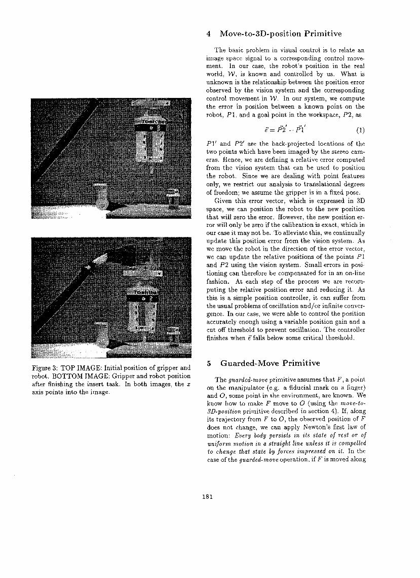
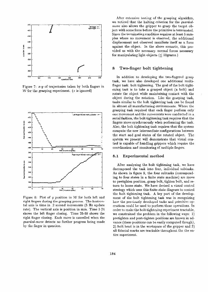
Figure 7 is a trace of the x-y positions in W moved to by the fingers during the experiment ( z is ignored). In both cases, the fingers move along a fairly smooth trajectory toward the bolt center before terminating with the guard condition. The smooth trajectory of both fingers is more obvious in figure 8. In this figure, we display the y positions of each finger as a function of time. From time 1-24, the left finger closes in upon the head of the bolt. From time 25-69, the right finger closes in upon the head of the bolt. Only the left finger moves during the left finger closing stage. And once, the left finger has stopped moving (the guard condi- tion being satisfied), the left finger ends it guarded move and the right finger starts moving. These results reinforce the idea that vision can be used to monitor the progress of a task and that vision can be used to determine when to switch between tasks.
Figure 6: Experimental setup showing the position of the fingers at the start of the two-fingered grasp exper- iment. Both fingers are not in contact with the bolt.
183
470 mfiRger -
ngM%nper -+-
a-
Figure 7: x-y of trajectories taken by both fingers in W for the grasping experiment. ( z is ignored)
I 0 10 20 30 40 M 60 70
t b (in cwlrd cydes)
Figure 8: Plot of y position in W for both left and right fingers during the grasping process. The horizon- tal axis is time in .2 second increments (5 Hz update rate). The vertical axis is position in mm. Time 1-24 shows the left finger closing. Time 25-69 shows the right finger closing. Each move is cancelled when the guarded-move detects no further progress being made by the finger in question.
After extensive testing of the grasping algorithm] we noticed that the halting criterion for the guarded- m o v e also allows the gripper to grasp the target ob- ject with some force before the primitive is terminated. Since the terminating condition requires at least 5 sam- ples where no movement is observed, the additional displacement not observed manifests itself as a force against the object. In the above scenario, this pro- vided us with the necessary normal forces necessary for manipulating light objects (5 50grams.)
8 Two-finger bolt tightening
In addition to developing the two-fingered grasp task, we have also developed one additional multi- finger task: bolt tightening. The goal of the bolt tight- ening task is to take a grasped object (a bolt) and rotate the object while maintaining contact with the object during the rotation. Like the grasping task, tasks similar to the bolt tightening task can be found in almost all manufacturing environments. Where the grasping task required that each finger perform only one movement and the movements were conducted in a serial fashion, the bolt tightening task requires that the fingers move synchronously when performing the task. Also, the bolt tightening task requires that the system compute the new intermediate configurations between the start and goal states of the rotated object. The system we present will demonstrate that visual con- trol is capable of handling grippers which require the coordination and monitoring of multiple fingers.
8.1 Experimental method
After analyzing the bolt tightening task, we have decomposed the task into four, individual subtasks. As shown in figure 9, the four subtasks (correspond- ing to four states in a finite state machine) are move to pretighten position, grasp bolt, tighten bolt, and re- turn to home state. We have devised a visual control strategy which uses this finite state diagram to control the bolt tightening task. A key part of the develop- ment of the bolt tightening task was in recognizing how the previously developed tasks and primitive op- erations could be used to perform these operations. In order to make the bolt tightening experiment tractable, we constrained the problem in the following ways: 1) pretighten and post-tighten positions are known in ad- vance (these positions can be easily computed though) ] 2) bolt head is in the workspace of the gripper and 3) all fiducial marks are trackable throughout the the en- tire experiment.
184
Pretighten
€r
Return home
Grasp
21-
Tighten
Figure 9: Finite state representation of the bolt tight- ening tasks. Two smaller circles represent fingers. The large circle with the rectangle through the center rep- resents the bolt head. Each node is an overhead view of the movement and position of the bolt and fingers during one part of the bolt tightening process.
8.2 Experimental results
Figure 6 shows the position of the gripper system at the start of the experiment. The fingers have been moved to the pretighten position. The fiducial marks used for feedback in this experiment are the marks clos- est to the tips of each finger (mounted on an extended structure attached to each finger tip).
After calling the grasp procedure, figure 10 shows the end position of the fingers after both guarded moves finished. The results of this grasping operation are very similar to the results presented in the previous section on grasping.
Figure 11 shows the position of the fingers after the tightening operation. While not obvious from the static picture, the fingers actually traveled in an arc around the rotational axis of the bolt. This footage is available in video form. This is also clearly shown in figure 13. Figure 13 shows the position where the fingers moved when the tighten task terminated. I t is an overhead shot showing the x and y positions of the points in W ignoring the z-coordinate values. This graph clearly shows the arc-like 3D trajectory taken by each fiducial mark as the gripper is ordered to tighten. This trajectory is resulted from the finger complying
Figure 10: Position of fingers after grasping portion of bolt tightening exDeriment.
Figure 11: Position of fingers after finishing the tight- ening operation.
Figure 12: The end position of the fingers after return- ing to home state.
185
470 Len finger c
Rgta linger +-
489-
Figure 13: x-y plot of 3D finger positions during the tightening phase of the experiment. ( z is ignored)
around the head of the bolt as it tried to satisfy the guarded move condition. Since the torques exerted by both fingers was sufficient to overcome the bolt's stic- tion and jammingforces, it was possible for the gripper to turn the bolt. If, on the other hand, the movement vector generated by the guarded move did not provide sufficient torque, the bolt would not have moved. It should also be noted that if the fingers did not comply around the head of the bolt, the tightening operation would not have been possible.
Figure 12 shows the final position of the fingers af- ter executing the return to home part of the task. The fingers were ordered to move to the post-tighten posi- tion and followed by a movement back to their initial starting position, the pretighten position. We present this figure for completeness to demonstrate the com- plete cycle of positions required for the bolt tightening operation.
Figure 14 shows how monitoring the feature associ- ated with the bolt can be used to determine the status of the tightening operation. In addition to the move- ment of the finger, this figure also displays the z-y movement of a fiducial mark on the head of the bolt. This result indicates that vision is also capable of mon- itoring the status of the tightening task. By observing the movement of bolt features, we can verify that the bolt head actually moved during a bolt tighten opera- tion. Without this information it would be difficult to determine if progress had been made in an assembly task. In many bolt tightening scenarios, it is possi- ble for the bolt to jam during the tightening phase. In these cases, it is very important to detect if and when jamming occurs. By detecting jamming early in the tightening cycle, it is possible prevent potentially costly repairs by taking remedial measures to cure the
~
186
470 I . X I
-4
-560 I I 1w 170 180 2M) 210 220 x p o s a i E m
Figure 14: Combined I-y plot for grasping and tight- ening experiment including the position of a fiducial mark on the bolt head (overhead view).
jamming condition. The potential jam condition could then be relayed back to a higher level process to prompt that task to take an alternative strategy to the current operation. We have not implemented such feedback but note that such a strategy is possible.
9 Conclusions
The key to our solution lies in the development of primitive visual control operations. The primitive vi- sual control operations allowed us to examine many of the real time problems associated with visual control in concise, manageable units. By decomposing a com- plex manipulation into a series of these operations, we removed much of the complexity associated with cre- ating a visual control system. Also, by developing the system in a modular fashion, we were able to reuse the primitive operations to solve a more complex task. We have also shown that such methods are readily adapted to different robot systems. For our experiments, we applied visual control techniques to both a standard Puma robot and to a non-standard pneumatic actua- tor, the Toshiba gripper. The Toshiba gripper provided a unique challenge for our controller. The gripper was capable of performing many compliant manipulations in spite of the fact that it was devoid of any feedback sensors. While the rigid metal surfaces of the Puma robot could have easily been outfitted with a "skin" of pressure sensors, the fingers of the Toshiba grip- per changed drastically during any operation thus in- creasing the difficulty of mounting and using many con- ventional pressure sensors. By implementing a vision- based robot control solution to this problem, we have
-
avoided this problem. Not only was it not necessary to add sensor to the fingers, but the results have shown that visual control is capable of performing many of the operations necessary for elementary manipulation. Future extensions to this work include the examination of the occlusion problem, how to detect slippage and how to estimate contact forces visually.
References
[I] P. Allen, A. Timcenko, B. Yoshimi, and P. Michel- man. Automated tracking and grasping of a moving object with a robotic hand-eye system. IEEE Trans. on Robotics and Automation, 9(2):152-165, 1993.
[2] A. Castano and S. Hutchinson. Visual compliance: Task-directed visual servo control. IEEE Trans. on Robotics and Automation, 10(3):334-342, June 1994.
[3] J. Feddema and C. S. G. Lee. Adaptive image feature prediction and control for visual tracking with a hand- eye coordinated camera. IEEE Transactions on Sys- tems, Man and Cybernetics, 20:1172-1183, Sept./Oct. 1990.
[4] G. Hager, W. Chang, and A. Morse. Robot feedback control based on stereo vision: Towards calibration- free hand-eye coordination. In Proc. IEEE Conf. on Robotics and Automation, volume 4, pages 2850-2856, 1994.
[5] N. Hollinghurst and R. Cipolla. Uncalibrated stereo hand-eye coordination. Technical Report CUED/F- INFENG/TR126, Department of Engineering, Univer- sity of Cambridge, 1993.
[6] A. Koivo and N. Houshangi. Real-time vision feed- back for servoing robotic manipulator with self-tuning controller. IEEE Transactions on System, Man, and Cybernetics, 21, No. 1334-142, Feb. 1991.
[7] N. Papanikolopoulos, B. Nelson, and P. Khosla. Six degree-of-freedom hand/eye visual tracking with un- certain parameters. In Proc. of IEEE International Conference on Robotics and Automation, pages 174- 179, May 1994.
[8] R. Sharma, J. Herve, and P. Cucka. Analysis of dy- namic hand positioning tasks using visual feedback. Technical Report CAR-TR-574, Center for Auto. Res., University of Maryland, 1991.
Camera- space manipulation. International Journal of Robotics Research, 6(4):20-32, Winter 1987.
[IO] T. M. Sobh and R. Bajcsy. Autonomous observation under uncertainty. In Proc. of IEEE International Conference on Robotics and Automation, pages 1792- 1798, May 1992.
Develop ment of a flexible microactuator and its application
191 S. Skaar, W. Brockman, and R. Hanson.
[11] K. Suzumori, S. Iikura, and H. Tanaka.
to robotic mechanisms. In IEEE International Con- ference of Robotics and Automation, pages 1622-1627, April 1991.
[12] B. H. Yoshimi. Visual Control of Robotics Tasks. PhD thesis, Department of Computer Science, Columbia University, May 1995.
1131 B. H. Yoshimi and P. Allen. Alignment using an un- calibrated camera system. In Proceedings: Image Un- derstanding Workshop, pages 411-420, 1993.