41
Kenneth Weddfelt Applied Mechanics Group, Special Engineering Services Rocktec Atlas Copco Rock Drills AB
Kenneth Weddfelt
Applied Mechanics Group, Special Engineering Services
Rocktec
Atlas Copco Rock Drills AB
2
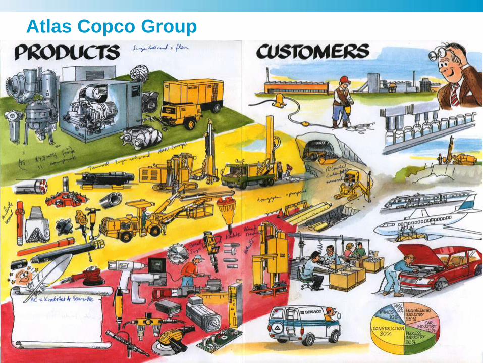
Atlas Copco Group
3
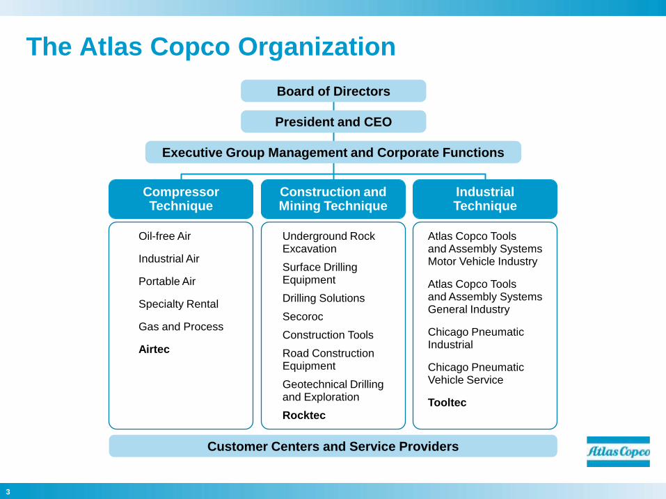
The Atlas Copco Organization
Executive Group Management and Corporate Functions
Oil-free Air
Industrial Air
Portable Air
Specialty Rental
Gas and Process
Airtec
CompressorTechnique
Construction and Mining Technique
IndustrialTechnique
Underground RockExcavation
Surface DrillingEquipment
Drilling Solutions
Secoroc
Construction Tools
Road Construction Equipment
Geotechnical Drillingand Exploration
Rocktec
Atlas Copco Tools and Assembly SystemsMotor Vehicle Industry
Atlas Copco Toolsand Assembly Systems General Industry
Chicago PneumaticIndustrial
Chicago PneumaticVehicle Service
Tooltec
Customer Centers and Service Providers
President and CEO
Board of Directors
4
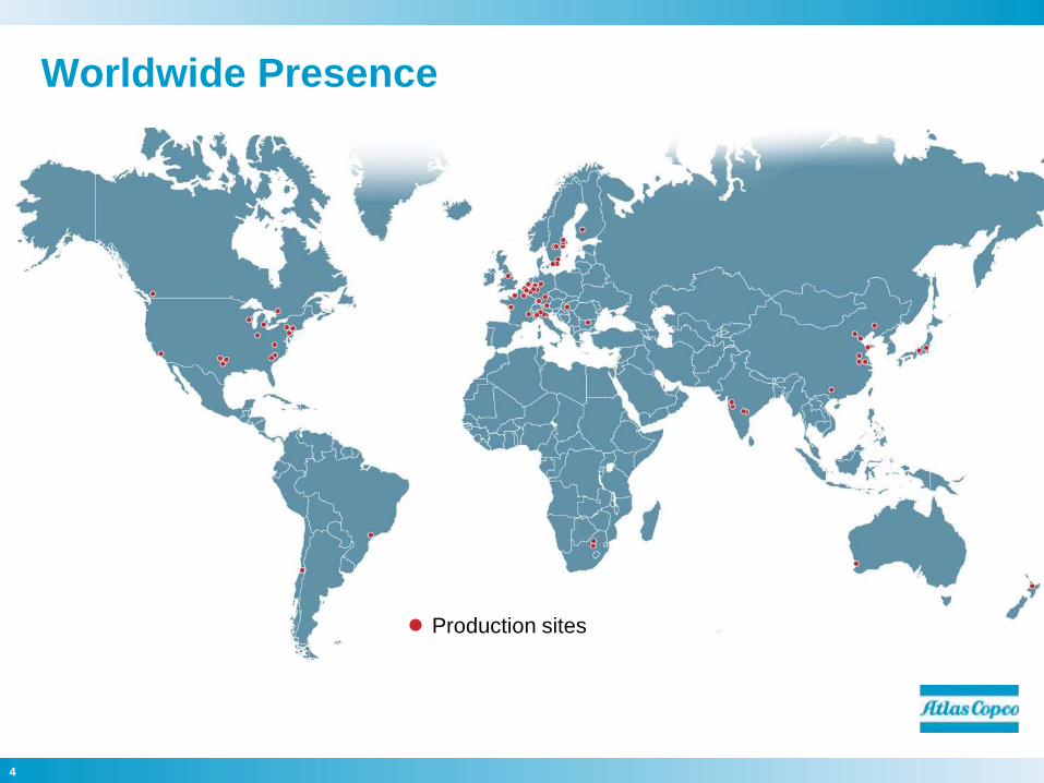
Worldwide Presence
Production sites
5
Strong Brands
6
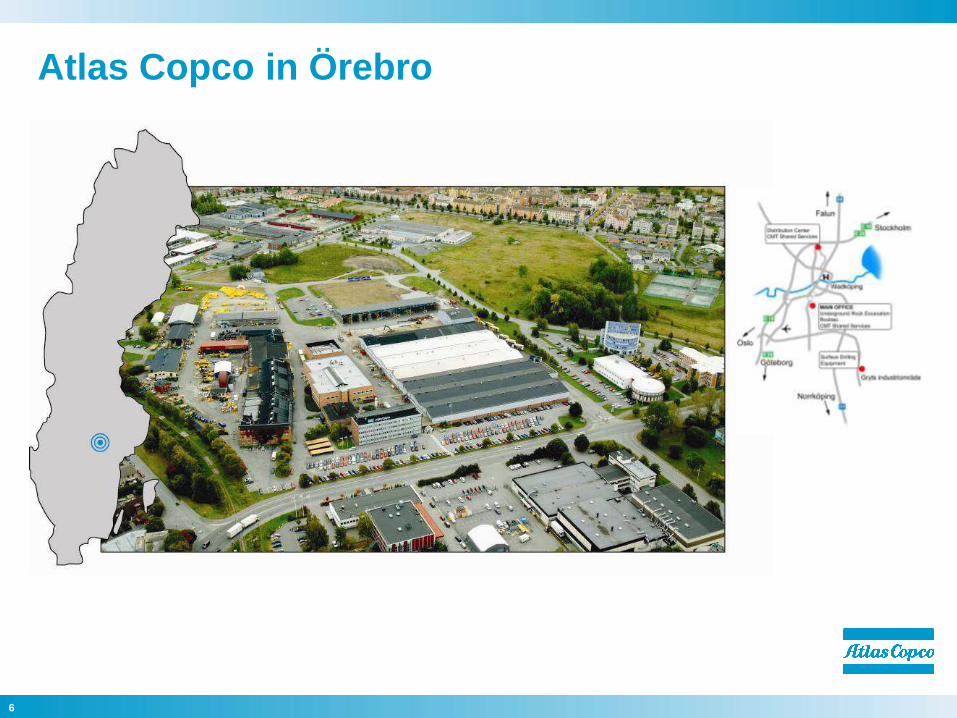
Atlas Copco in Örebro
7
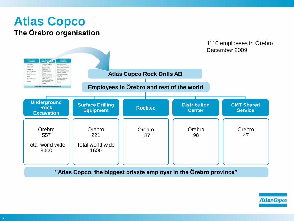
Örebro557
Total world wide 3300
Atlas Copco Rock Drills AB
Employees in Örebro and rest of the world
UndergroundRock
Excavation
Surface DrillingEquipment
RocktecDistribution
CenterCMT Shared
Service
Örebro221
Total world wide 1600
Örebro187
Örebro98
Örebro47
”Atlas Copco, the biggest private employer in the Örebro province”
1110 employees in Örebro
December 2009
Atlas Copco The Örebro organisation
8
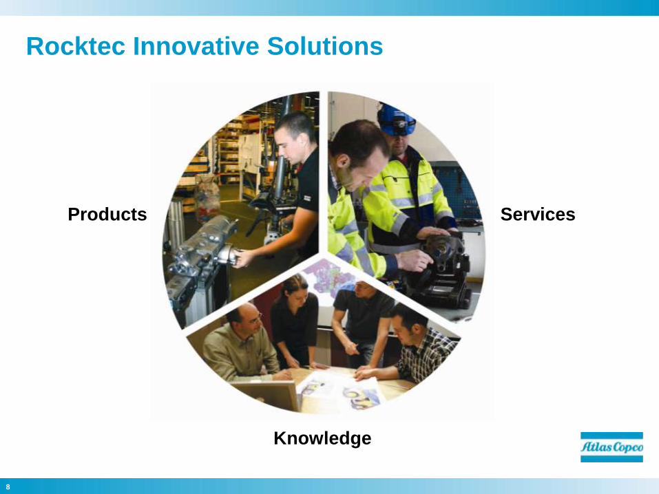
Rocktec Innovative Solutions
Products Services
Knowledge

9
Vision
To be First in Mind—First in Choice ® for Rock Drills, Automation Solutions
and Specialist Engineering Services.

Specialist Engineering Services
11
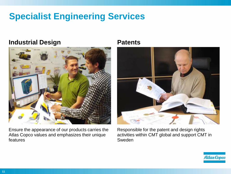
Industrial Design Patents
Ensure the appearance of our products carries the Atlas Copco values and emphasizes their unique features
Responsible for the patent and design rights activities within CMT global and support CMT in Sweden
Specialist Engineering Services
12
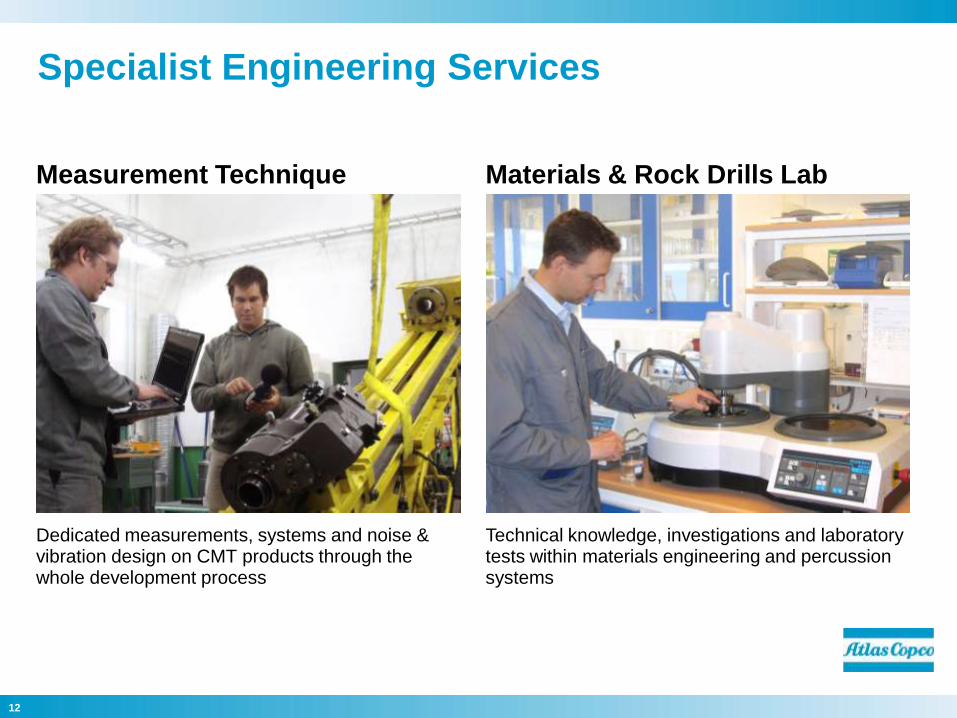
Measurement Technique Materials & Rock Drills Lab
Dedicated measurements, systems and noise & vibration design on CMT products through the whole development process
Technical knowledge, investigations and laboratory tests within materials engineering and percussion systems
Specialist Engineering Services
13
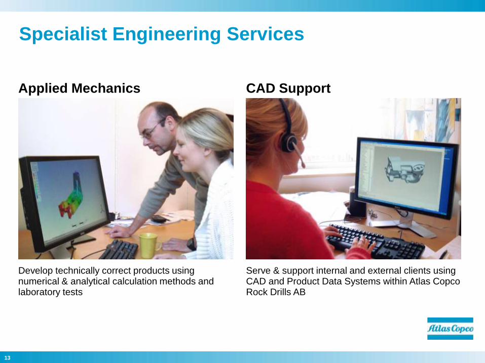
Applied Mechanics CAD Support
Develop technically correct products using numerical & analytical calculation methods and laboratory tests
Serve & support internal and external clients using CAD and Product Data Systems within Atlas Copco Rock Drills AB
Specialist Engineering Services
14
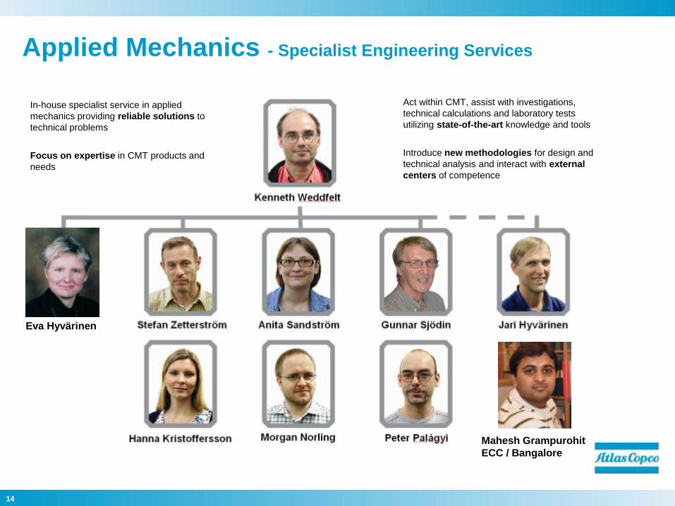
Applied Mechanics - Specialist Engineering Services
Eva Hyvärinen
In-house specialist service in applied
mechanics providing reliable solutions to
technical problems
Focus on expertise in CMT products and
needs
Act within CMT, assist with investigations,
technical calculations and laboratory tests
utilizing state-of-the-art knowledge and tools
Introduce new methodologies for design and
technical analysis and interact with external
centers of competence
Mahesh Grampurohit
ECC / Bangalore
15
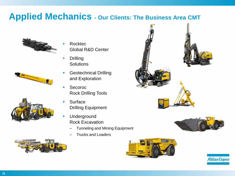
Rocktec
Global R&D Center
Drilling
Solutions
Geotechnical Drilling
and Exploration
Secoroc
Rock Drilling Tools
Surface
Drilling Equipment
Underground
Rock Excavation
– Tunneling and Mining Equipment
– Trucks and Loaders
Applied Mechanics - Our Clients: The Business Area CMT
16
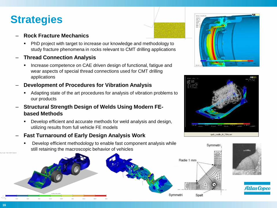
Strategies
– Rock Fracture Mechanics
PhD project with target to increase our knowledge and methodology to
study fracture phenomena in rocks relevant to CMT drilling applications
– Thread Connection Analysis
Increase competence on CAE driven design of functional, fatigue and
wear aspects of special thread connections used for CMT drilling
applications
– Development of Procedures for Vibration Analysis
Adapting state of the art procedures for analysis of vibration problems to
our products
– Structural Strength Design of Welds Using Modern FE-
based Methods
Develop efficient and accurate methods for weld analysis and design,
utilizing results from full vehicle FE models
– Fast Turnaround of Early Design Analysis Work
Develop efficient methodology to enable fast component analysis while
still retaining the macroscopic behavior of vehicles

17
Committed to
sustainable productivity.

18
19
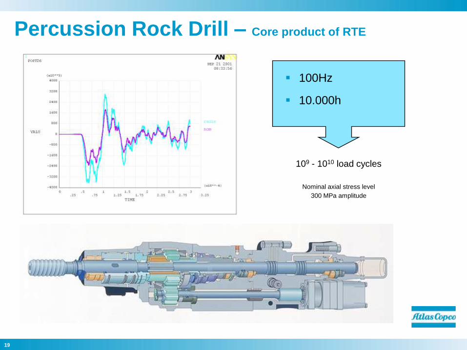
Percussion Rock Drill – Core product of RTE
100Hz
10.000h
109 - 1010 load cycles
Nominal axial stress level
300 MPa amplitude
20
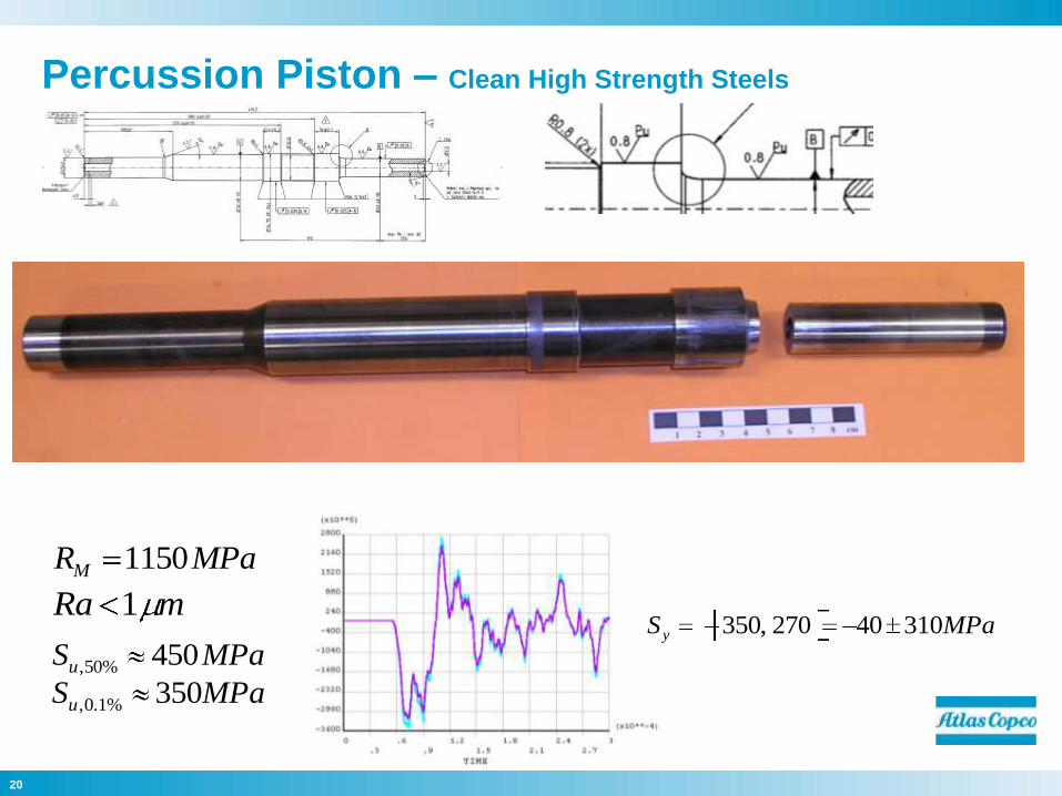
Percussion Piston – Clean High Strength Steels
MPaSu 450%50,
mRa 1
MPaRM 1150
MPaSu 350%1.0,
MPaSy 31040270,350
21
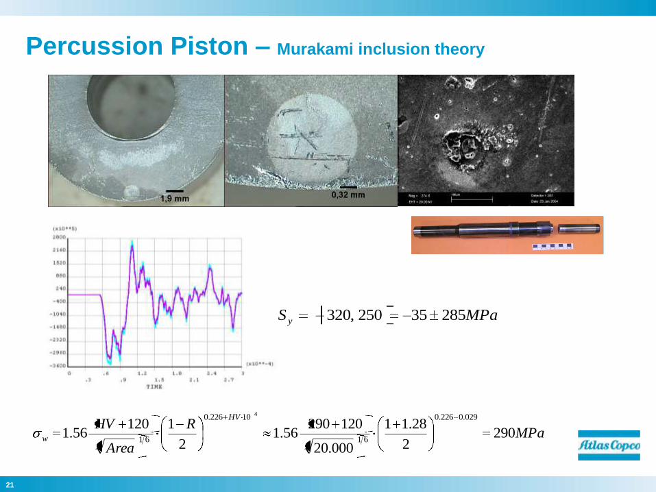
Percussion Piston – Murakami inclusion theory
MPaR
Area
HVHV
w 2902
28.11
000.20
12029056.1
2
112056.1
029.0226.0
61
10226.0
61
4
MPaS y 28535250,320
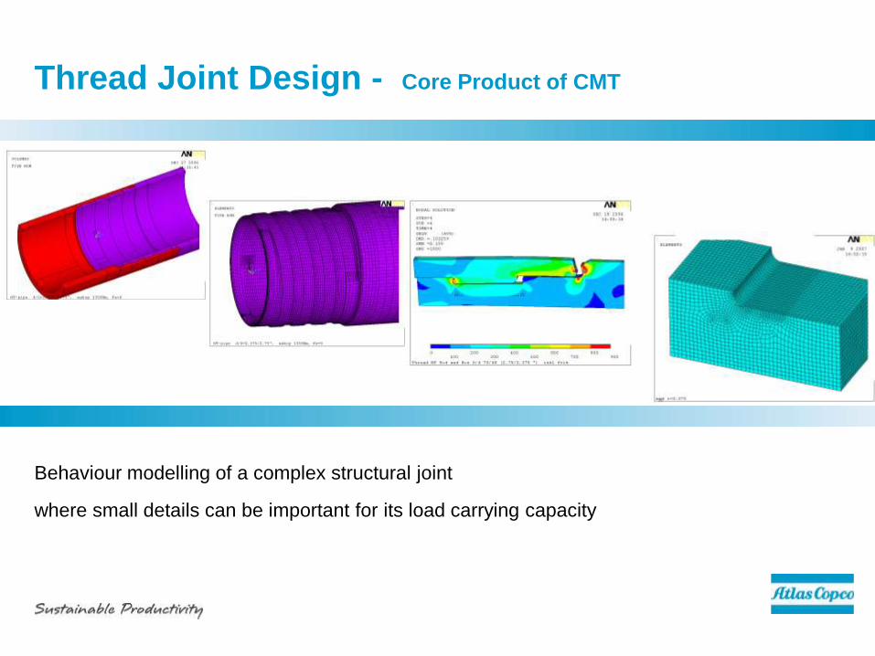
Thread Joint Design - Core Product of CMT
Behaviour modelling of a complex structural joint
where small details can be important for its load carrying capacity
23
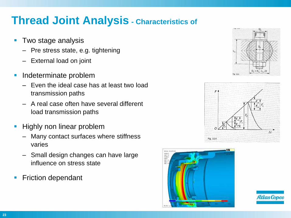
Thread Joint Analysis - Characteristics of
Two stage analysis
– Pre stress state, e.g. tightening
– External load on joint
Indeterminate problem
– Even the ideal case has at least two load
transmission paths
– A real case often have several different
load transmission paths
Highly non linear problem
– Many contact surfaces where stiffness
varies
– Small design changes can have large
influence on stress state
Friction dependant
24
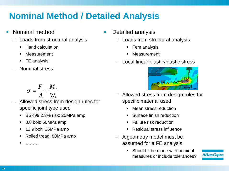
Nominal Method / Detailed Analysis
Nominal method
– Loads from structural analysis
Hand calculation
Measurement
FE analysis
– Nominal stress
– Allowed stress from design rules for
specific joint type used
BSK99 2.3% risk: 25MPa amp
8.8 bolt: 50MPa amp
12.9 bolt: 35MPa amp
Rolled tread: 80MPa amp
………
Detailed analysis
– Loads from structural analysis
Fem analysis
Measurement
– Local linear elastic/plastic stress
– Allowed stress from design rules for
specific material used
Mean stress reduction
Surface finish reduction
Failure risk reduction
Residual stress influence
– A geometry model must be
assumed for a FE analysis
Should it be made with nominal
measures or include tolerances?
b
b
W
M
A
F
25
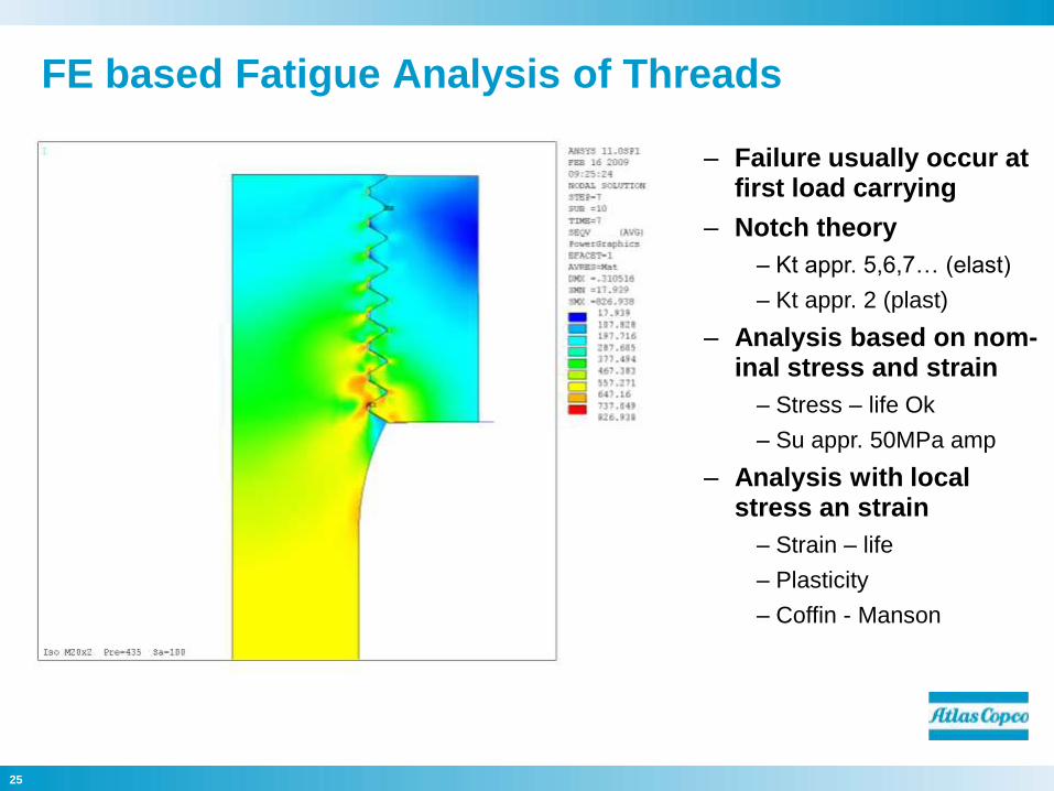
FE based Fatigue Analysis of Threads
– Failure usually occur at first load carrying
– Notch theory
– Kt appr. 5,6,7… (elast)
– Kt appr. 2 (plast)
– Analysis based on nom-inal stress and strain
– Stress – life Ok
– Su appr. 50MPa amp
– Analysis with local stress an strain
– Strain – life
– Plasticity
– Coffin - Manson
26
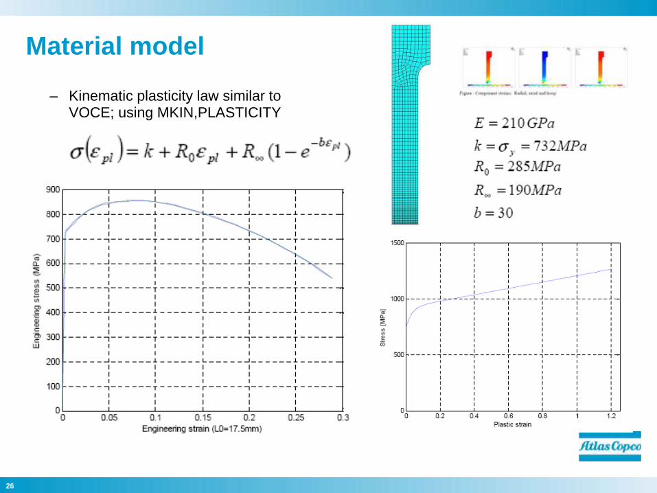
Material model
– Kinematic plasticity law similar to VOCE; using MKIN,PLASTICITY
27
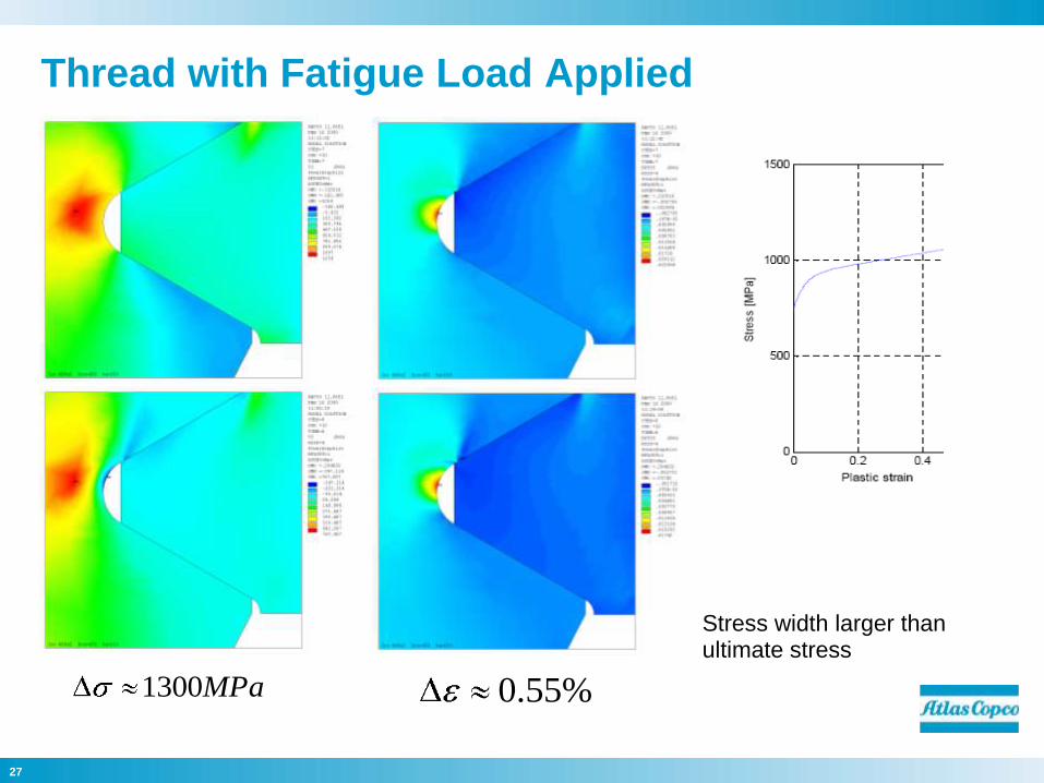
Thread with Fatigue Load Applied
MPa1300 %55.0
Stress width larger than ultimate stress
28
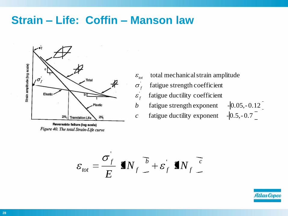
Strain – Life: Coffin – Manson law
c
ff
b
f
f
tot NNE
22 '
'
c
ff
b
f
f
tot NNE
22 '
'
0.7-0.5,-exponentductilityfatigue
0.12-0.05,-exponentstrengthfatigue
tcoefficienductilityfatigue
tcoefficienstrengthfatigue
amplitudestrainmechanicaltotal
'
'
c
b
f
f
tot
29
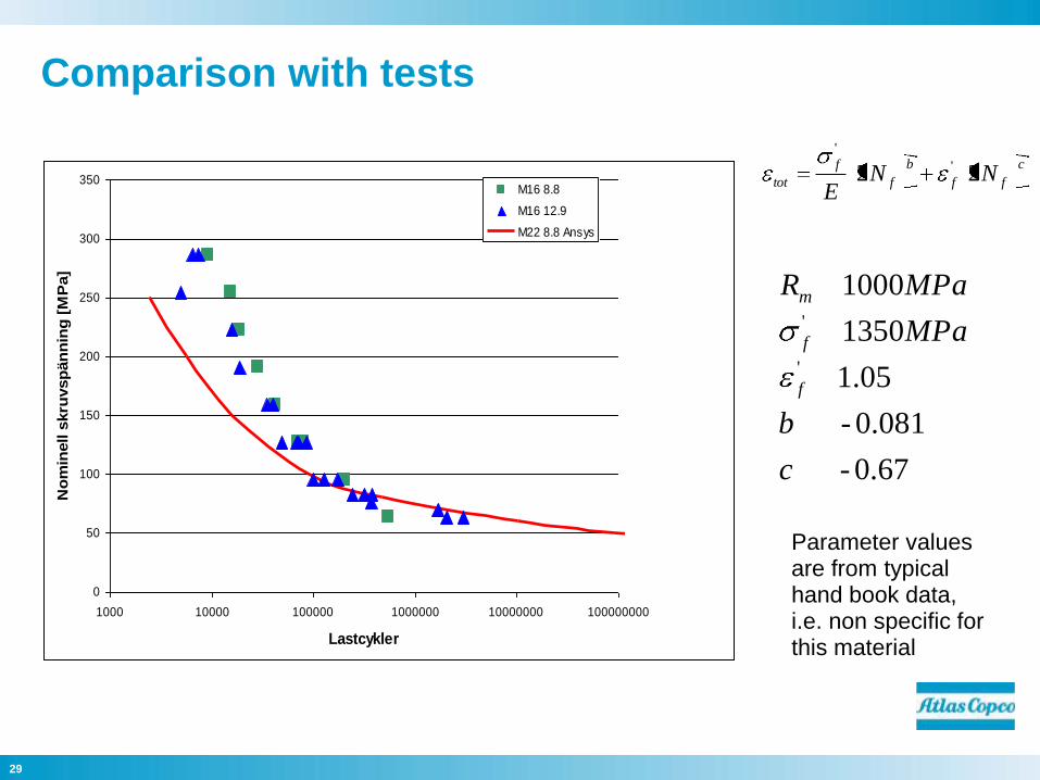
Comparison with tests
67.0-
081.0-
05.1
3501
0001
'
'
c
b
MPa
MPaR
f
f
m
c
ff
b
f
f
tot NNE
22 '
'
Parameter values are from typical hand book data, i.e. non specific for this material
0
50
100
150
200
250
300
350
1000 10000 100000 1000000 10000000 100000000
Lastcykler
No
min
ell s
kru
vsp
än
nin
g [
MP
a]
M16 8.8
M16 12.9
M22 8.8 Ansys
30
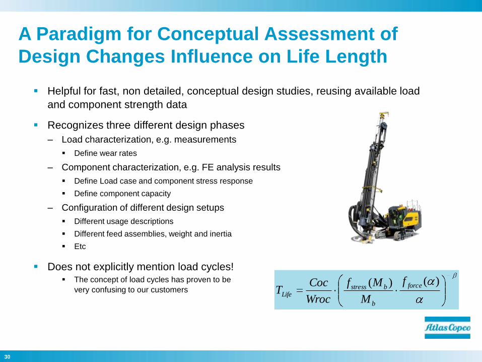
A Paradigm for Conceptual Assessment of
Design Changes Influence on Life Length
Helpful for fast, non detailed, conceptual design studies, reusing available load
and component strength data
Recognizes three different design phases
– Load characterization, e.g. measurements
Define wear rates
– Component characterization, e.g. FE analysis results
Define Load case and component stress response
Define component capacity
– Configuration of different design setups
Different usage descriptions
Different feed assemblies, weight and inertia
Etc
Does not explicitly mention load cycles! The concept of load cycles has proven to be
very confusing to our customers)()( force
b
bstressLife
f
M
Mf
Wroc
CocT
31
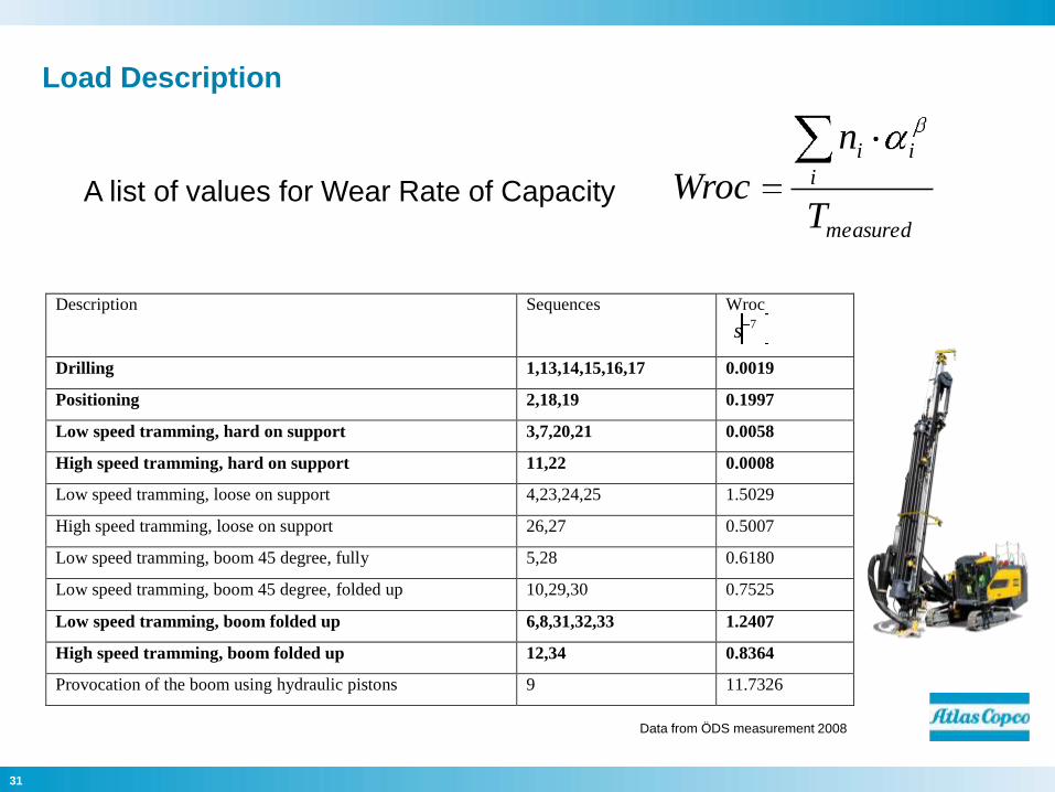
Load Description
Description Sequences Wroc 7s
Drilling 1,13,14,15,16,17 0.0019
Positioning 2,18,19 0.1997
Low speed tramming, hard on support 3,7,20,21 0.0058
High speed tramming, hard on support 11,22 0.0008
Low speed tramming, loose on support 4,23,24,25 1.5029
High speed tramming, loose on support 26,27 0.5007
Low speed tramming, boom 45 degree, fully 5,28 0.6180
Low speed tramming, boom 45 degree, folded up 10,29,30 0.7525
Low speed tramming, boom folded up 6,8,31,32,33 1.2407
High speed tramming, boom folded up 12,34 0.8364
Provocation of the boom using hydraulic pistons 9 11.7326
measured
i
ii
T
n
WrocA list of values for Wear Rate of Capacity
Data from ÖDS measurement 2008
32
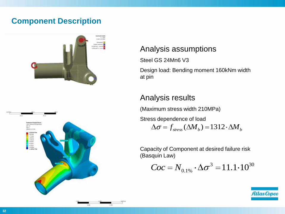
Component Description
Analysis assumptions
Steel GS 24Mn6 V3
Design load: Bending moment 160kNm width
at pin
Analysis results
(Maximum stress width 210MPa)
Stress dependence of load
Capacity of Component at desired failure risk
(Basquin Law)
bbstress MMf 1312)(
303
%1.0 101.11NCoc
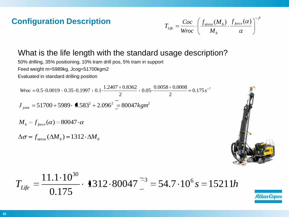
33
Configuration Description
222 80047096.2583.0598951700 kgmJ joint
What is the life length with the standard usage description?50% drilling, 35% positioning, 10% tram drill pos, 5% tram in support
Feed weight m=5989kg, Jcog=51700kgm2
Evaluated in standard drilling position
7175.02
0008.00058.005.0
2
8362.02407.11.01997.035.00019.05.0 sWroc
80047)(forceb fM
)()( force
b
bstressLife
f
M
Mf
Wroc
CocT
hsTLife 15211107.54800471312175.0
101.11 6330
bbstress MMf 1312)(
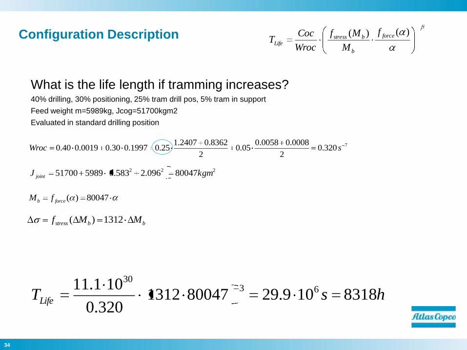
34
Configuration Description
222 80047096.2583.0598951700 kgmJ joint
What is the life length if tramming increases?40% drilling, 30% positioning, 25% tram drill pos, 5% tram in support
Feed weight m=5989kg, Jcog=51700kgm2
Evaluated in standard drilling position
7320.02
0008.00058.005.0
2
8362.02407.125.01997.030.00019.040.0 sWroc
80047)(forceb fM
)()( force
b
bstressLife
f
M
Mf
Wroc
CocT
hsTLife 8318109.29800471312320.0
101.11 6330
bbstress MMf 1312)(
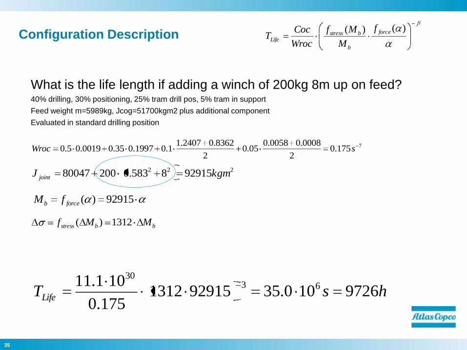
35
Configuration Description
222 929158583.020080047 kgmJ joint
What is the life length if adding a winch of 200kg 8m up on feed?40% drilling, 30% positioning, 25% tram drill pos, 5% tram in support
Feed weight m=5989kg, Jcog=51700kgm2 plus additional component
Evaluated in standard drilling position
92915)(forceb fM
)()( force
b
bstressLife
f
M
Mf
Wroc
CocT
hsTLife 9726100.35929151312175.0
101.11 6330
7175.02
0008.00058.005.0
2
8362.02407.11.01997.035.00019.05.0 sWroc
bbstress MMf 1312)(
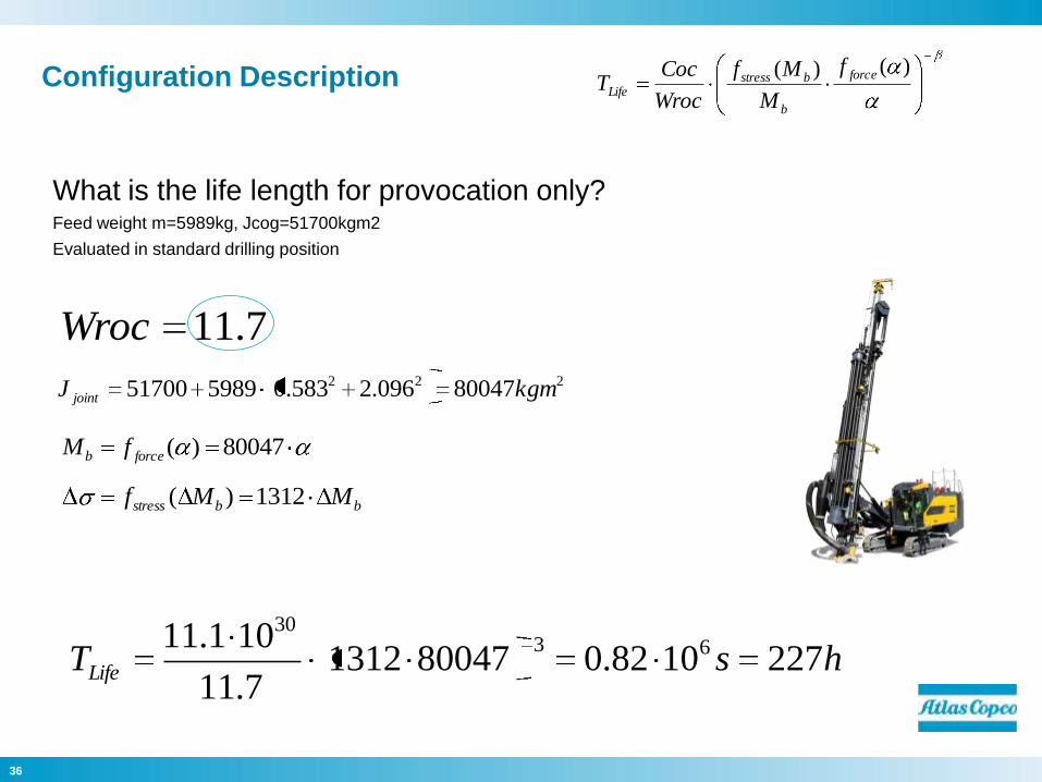
36
Configuration Description
222 80047096.2583.0598951700 kgmJ joint
What is the life length for provocation only?Feed weight m=5989kg, Jcog=51700kgm2
Evaluated in standard drilling position
7.11Wroc
80047)(forceb fM
)()( force
b
bstressLife
f
M
Mf
Wroc
CocT
hsTLife 2271082.08004713127.11
101.11 6330
bbstress MMf 1312)(
37
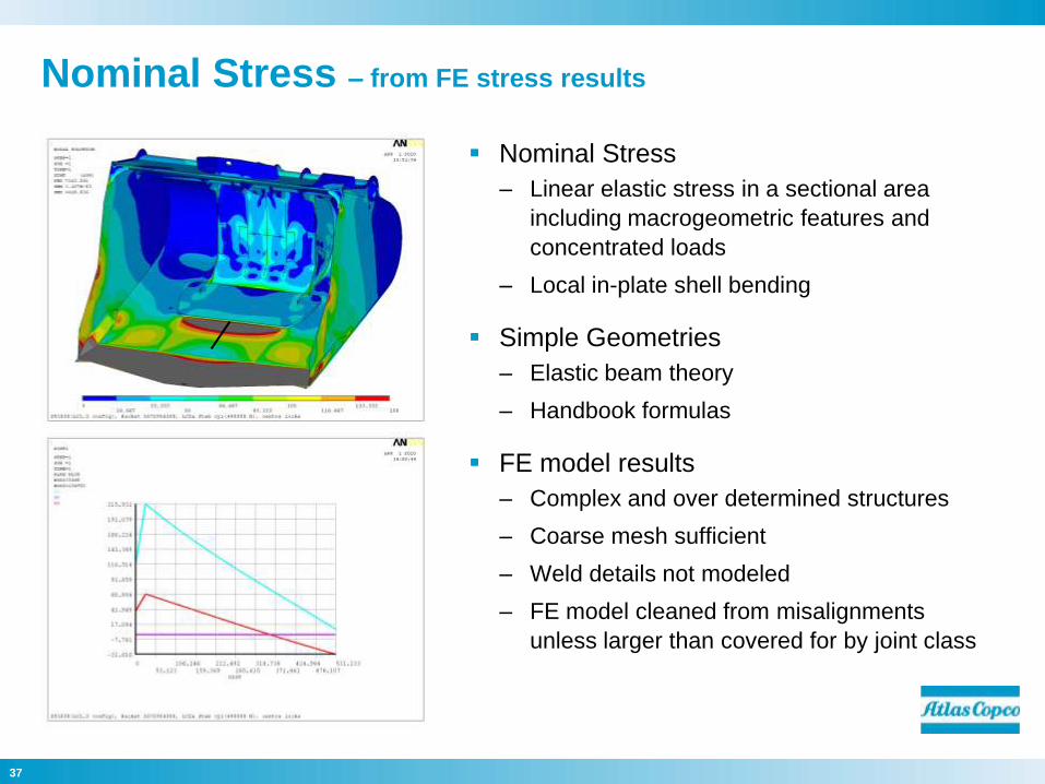
Nominal Stress – from FE stress results
Nominal Stress
– Linear elastic stress in a sectional area
including macrogeometric features and
concentrated loads
– Local in-plate shell bending
Simple Geometries
– Elastic beam theory
– Handbook formulas
FE model results
– Complex and over determined structures
– Coarse mesh sufficient
– Weld details not modeled
– FE model cleaned from misalignments
unless larger than covered for by joint class
38
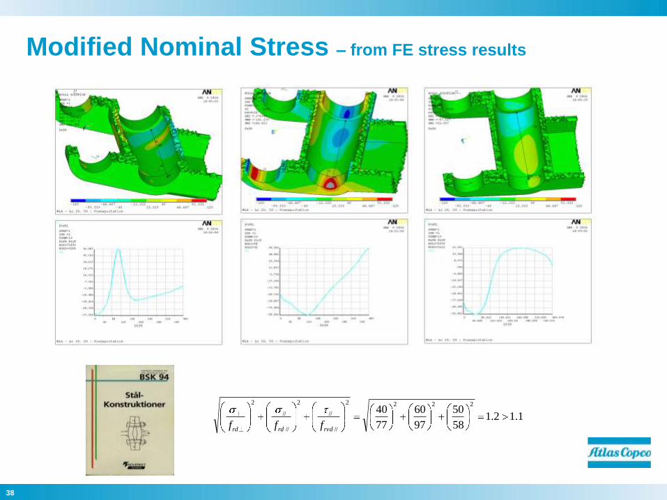
Modified Nominal Stress – from FE stress results
1.12.158
50
97
60
77
402222
//
//
2
//
//
2
rvdrdrd fff
39
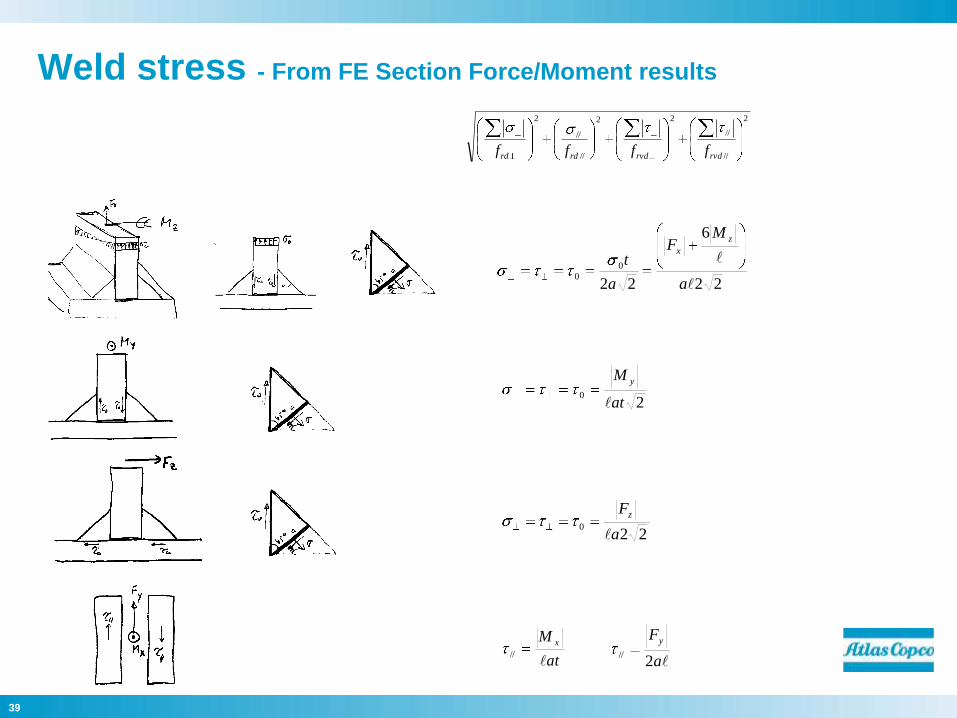
Weld stress - From FE Section Force/Moment results
22
6
22
0
0
a
MF
a
t
z
x
20
at
M y
220
a
Fz
at
M x
//
a
Fy
2//
2
//
//
22
//
//
2
rvdrvdrdrd ffff
40
Committed to
sustainable productivity.