40
ATM switching Ram Dantu
| Date post: | 30-Dec-2015 |
| Category: |
Documents |
| Upload: | jewel-aileen-riley |
| View: | 220 times |
| Download: | 0 times |

ATM switching
Ram Dantu
Introduction
• Important characteristics– switching speed– potential to lose cells
• Must minimize– queuing and switching delay
• Line rates may be > 150Mbps
• Available switching rates are ~80Gbps
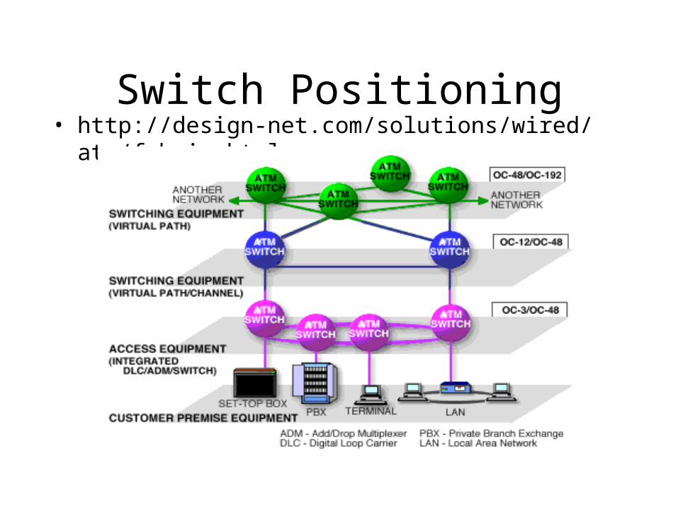
Switch Positioning• http://design-net.com/solutions/wired/atm/fabric.html
Switch Fabric
• Components of a switch which include its hardware and software
• General switch operation– routing table– self routing– new header inserted in outbound cell
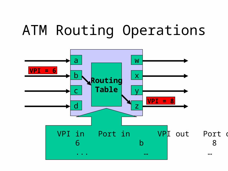
ATM Routing Operations
a
b
c
d
w
x
y
z
RoutingTable
VPI in Port in VPI out Port out 6 b 8 x ... … … ...
VPI = 6
VPI = 8
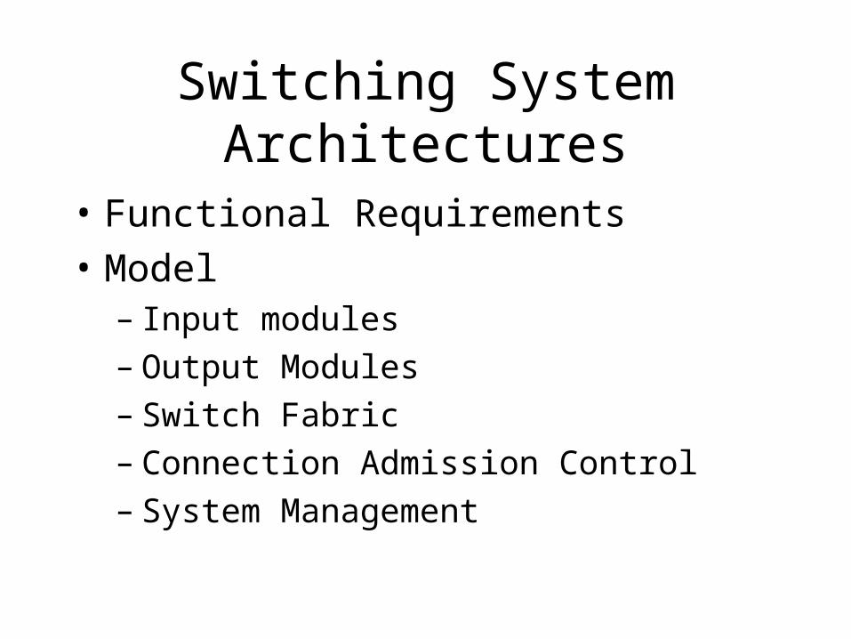
Switching System Architectures
• Functional Requirements
• Model– Input modules– Output Modules– Switch Fabric– Connection Admission Control– System Management
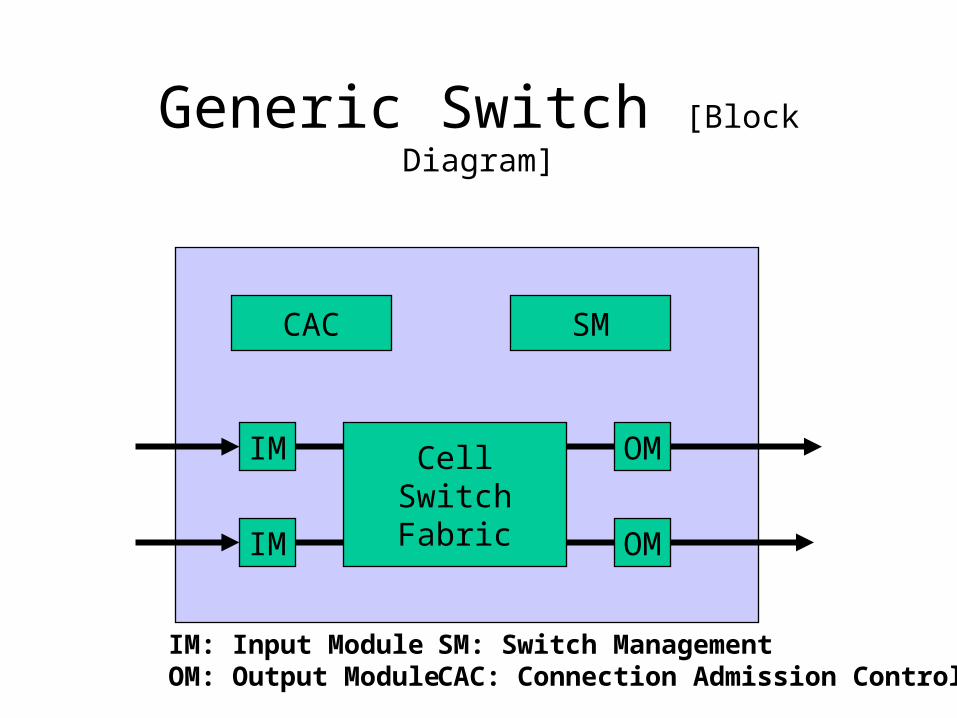
Generic Switch [Block Diagram]
CAC SM
CellSwitchFabric
IM
IM
OM
OM
IM: Input ModuleOM: Output Module
SM: Switch ManagementCAC: Connection Admission Control
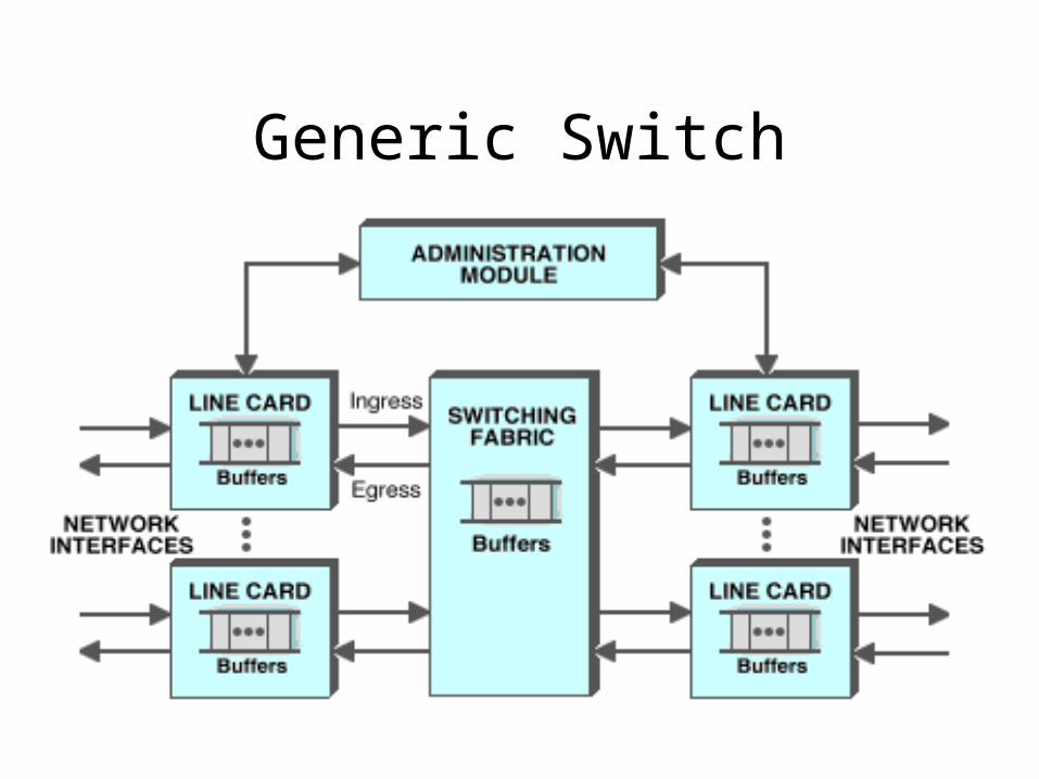
Generic Switch
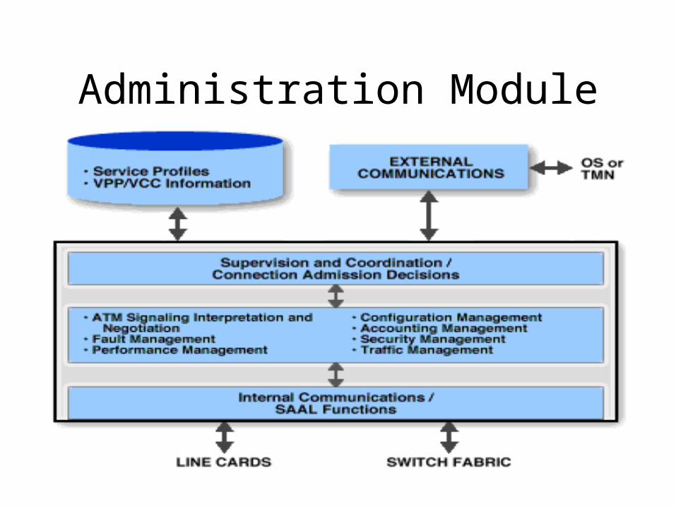
Administration Module
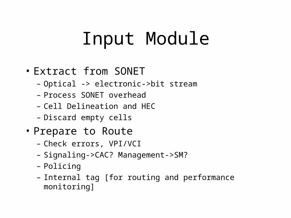
Input Module
• Extract from SONET– Optical -> electronic->bit stream– Process SONET overhead– Cell Delineation and HEC– Discard empty cells
• Prepare to Route– Check errors, VPI/VCI– Signaling->CAC? Management->SM?– Policing– Internal tag [for routing and performance monitoring]
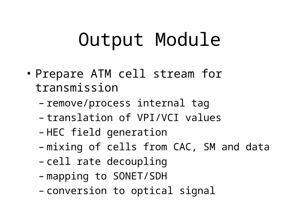
Output Module
• Prepare ATM cell stream for transmission– remove/process internal tag– translation of VPI/VCI values– HEC field generation– mixing of cells from CAC, SM and data– cell rate decoupling– mapping to SONET/SDH– conversion to optical signal
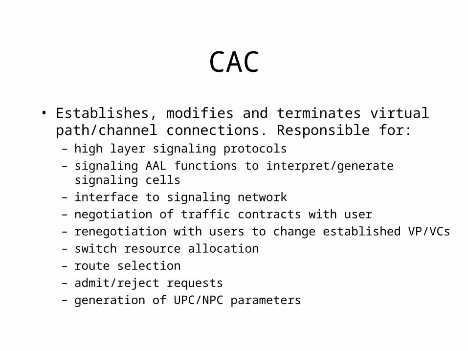
CAC
• Establishes, modifies and terminates virtual path/channel connections. Responsible for:– high layer signaling protocols
– signaling AAL functions to interpret/generate signaling cells
– interface to signaling network
– negotiation of traffic contracts with user
– renegotiation with users to change established VP/VCs
– switch resource allocation
– route selection
– admit/reject requests
– generation of UPC/NPC parameters
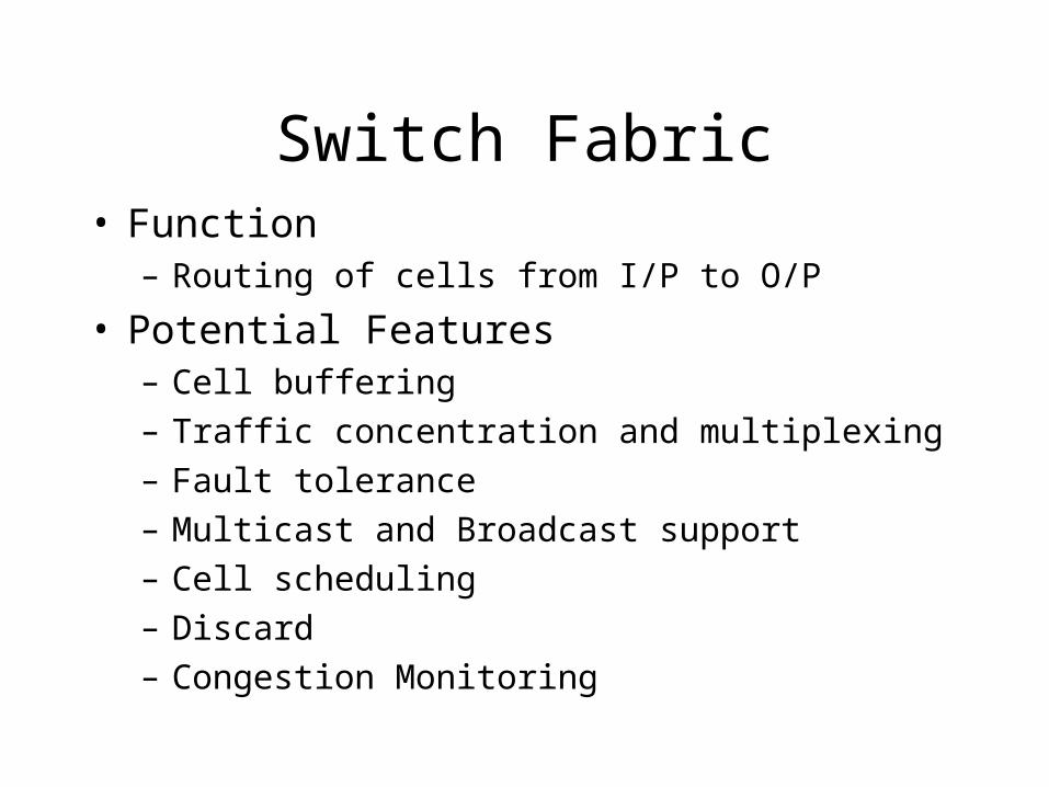
Switch Fabric• Function
– Routing of cells from I/P to O/P
• Potential Features– Cell buffering
– Traffic concentration and multiplexing
– Fault tolerance
– Multicast and Broadcast support
– Cell scheduling
– Discard
– Congestion Monitoring
Switch Fabric
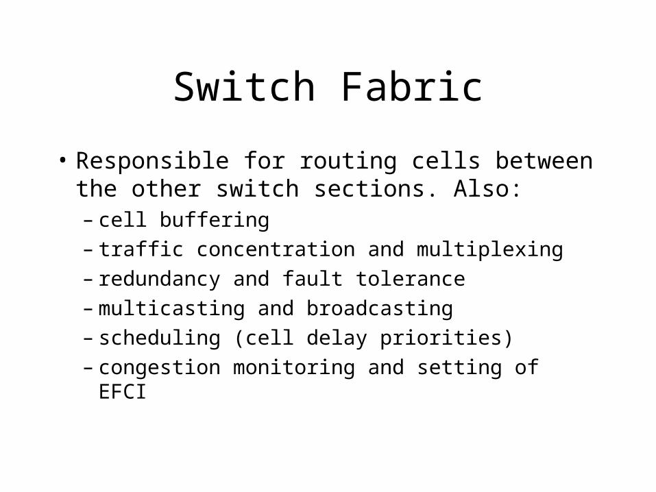
• Responsible for routing cells between the other switch sections. Also:– cell buffering– traffic concentration and multiplexing– redundancy and fault tolerance– multicasting and broadcasting– scheduling (cell delay priorities)– congestion monitoring and setting of EFCI
Routing and Buffering
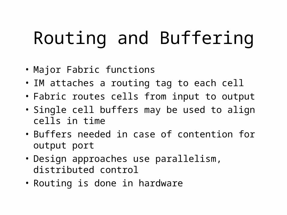
• Major Fabric functions• IM attaches a routing tag to each cell• Fabric routes cells from input to output• Single cell buffers may be used to align cells in time• Buffers needed in case of contention for output port• Design approaches use parallelism, distributed control • Routing is done in hardware
Fabric Design Approaches
• Shared Memory
• Shared Medium
• Fully Interconnected
• Space Division
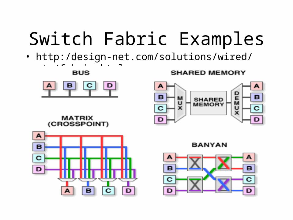
Switch Fabric Examples• http:/design-net.com/solutions/wired/atm/fabric.html
Shared Memory
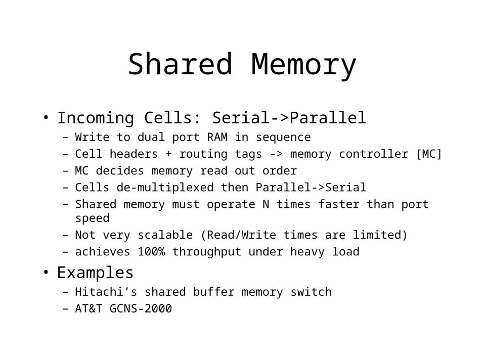
• Incoming Cells: Serial->Parallel– Write to dual port RAM in sequence– Cell headers + routing tags -> memory controller [MC]– MC decides memory read out order– Cells de-multiplexed then Parallel->Serial– Shared memory must operate N times faster than port speed– Not very scalable (Read/Write times are limited)– achieves 100% throughput under heavy load
• Examples– Hitachi’s shared buffer memory switch– AT&T GCNS-2000
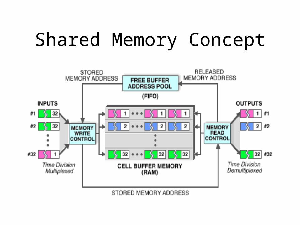
Shared Memory Concept
– http:/design-net.com/solutions/wired/atm/fabric.html
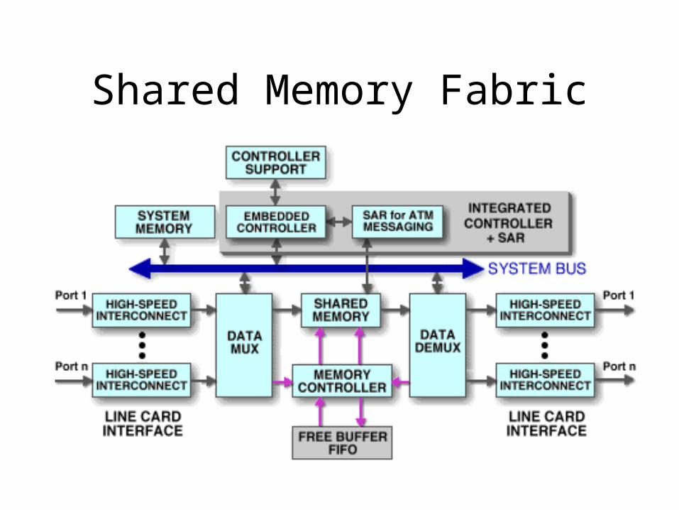
Shared Memory Fabric
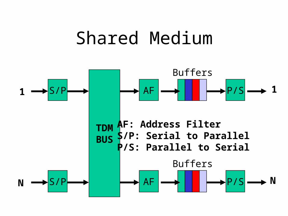
Shared Medium
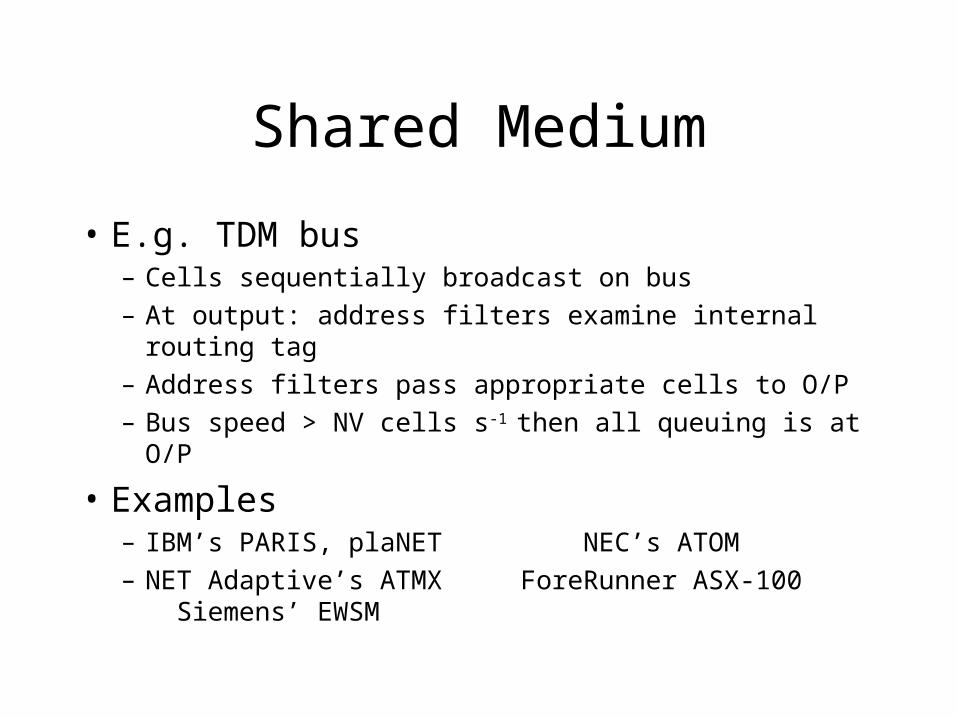
• E.g. TDM bus– Cells sequentially broadcast on bus
– At output: address filters examine internal routing tag
– Address filters pass appropriate cells to O/P
– Bus speed > NV cells s-1 then all queuing is at O/P
• Examples– IBM’s PARIS, plaNET NEC’s ATOM
– NET Adaptive’s ATMX ForeRunner ASX-100 Siemens’ EWSM
Shared Medium
TDMBUS
S/P AF P/S
Buffers
S/P AF P/S
Buffers
1
N
1
N
AF: Address FilterS/P: Serial to ParallelP/S: Parallel to Serial
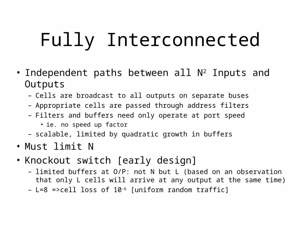
Fully Interconnected
• Independent paths between all N2 Inputs and Outputs– Cells are broadcast to all outputs on separate buses– Appropriate cells are passed through address filters– Filters and buffers need only operate at port speed
• ie. no speed up factor
– scalable, limited by quadratic growth in buffers
• Must limit N• Knockout switch [early design]
– limited buffers at O/P: not N but L (based on an observation that only L cells will arrive at any output at the same time)
– L=8 =>cell loss of 10-6 [uniform random traffic]

Fully Interconnected
AF AF AF
12N
AF AF AFAddress Filters
Buffers
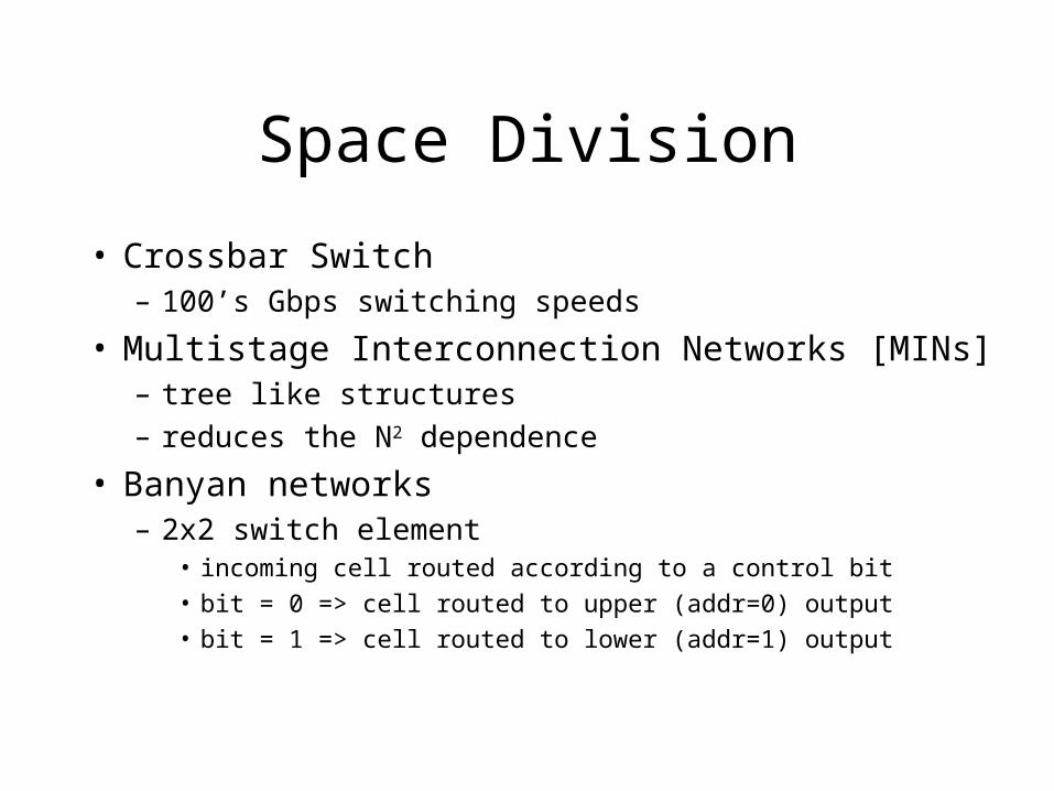
Space Division
• Crossbar Switch– 100’s Gbps switching speeds
• Multistage Interconnection Networks [MINs]– tree like structures– reduces the N2 dependence
• Banyan networks– 2x2 switch element
• incoming cell routed according to a control bit
• bit = 0 => cell routed to upper (addr=0) output
• bit = 1 => cell routed to lower (addr=1) output
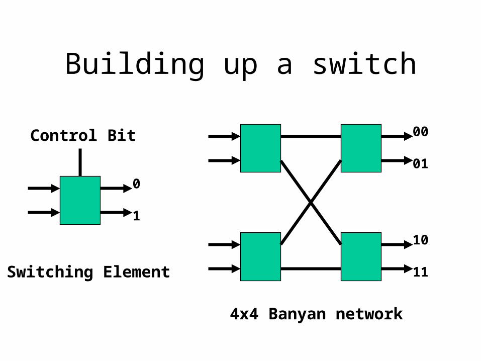
Building up a switch
Control Bit
0
1
00
01
10
11Switching Element
4x4 Banyan network
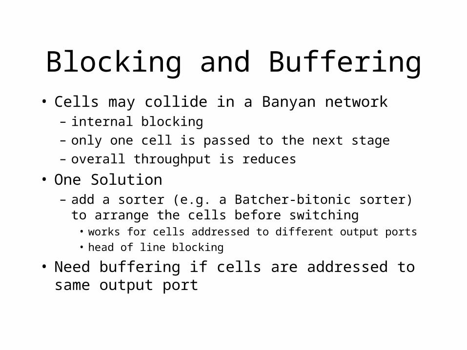
Blocking and Buffering• Cells may collide in a Banyan network
– internal blocking– only one cell is passed to the next stage– overall throughput is reduces
• One Solution– add a sorter (e.g. a Batcher-bitonic sorter) to arrange the cells
before switching• works for cells addressed to different output ports• head of line blocking
• Need buffering if cells are addressed to same output port
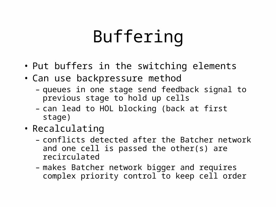
Buffering
• Put buffers in the switching elements• Can use backpressure method
– queues in one stage send feedback signal to previous stage to hold up cells
– can lead to HOL blocking (back at first stage)
• Recalculating– conflicts detected after the Batcher network and one
cell is passed the other(s) are recirculated– makes Batcher network bigger and requires complex
priority control to keep cell order
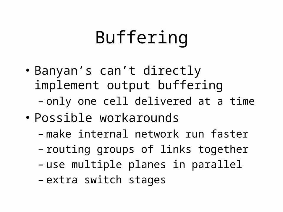
Buffering
• Banyan’s can’t directly implement output buffering– only one cell delivered at a time
• Possible workarounds– make internal network run faster– routing groups of links together– use multiple planes in parallel– extra switch stages
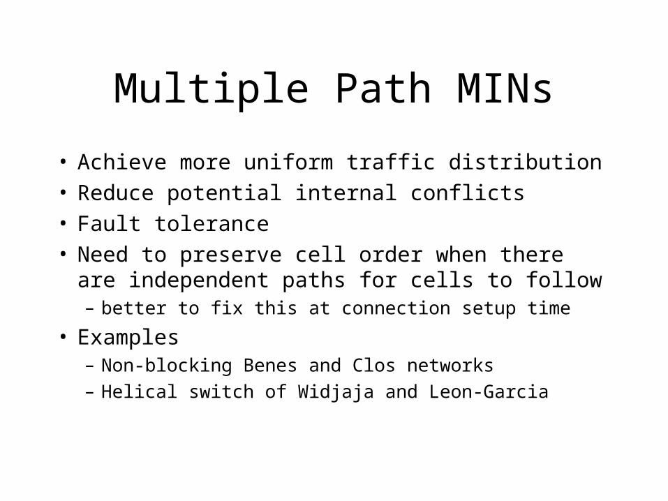
Multiple Path MINs
• Achieve more uniform traffic distribution • Reduce potential internal conflicts • Fault tolerance• Need to preserve cell order when there are
independent paths for cells to follow– better to fix this at connection setup time
• Examples– Non-blocking Benes and Clos networks
– Helical switch of Widjaja and Leon-Garcia
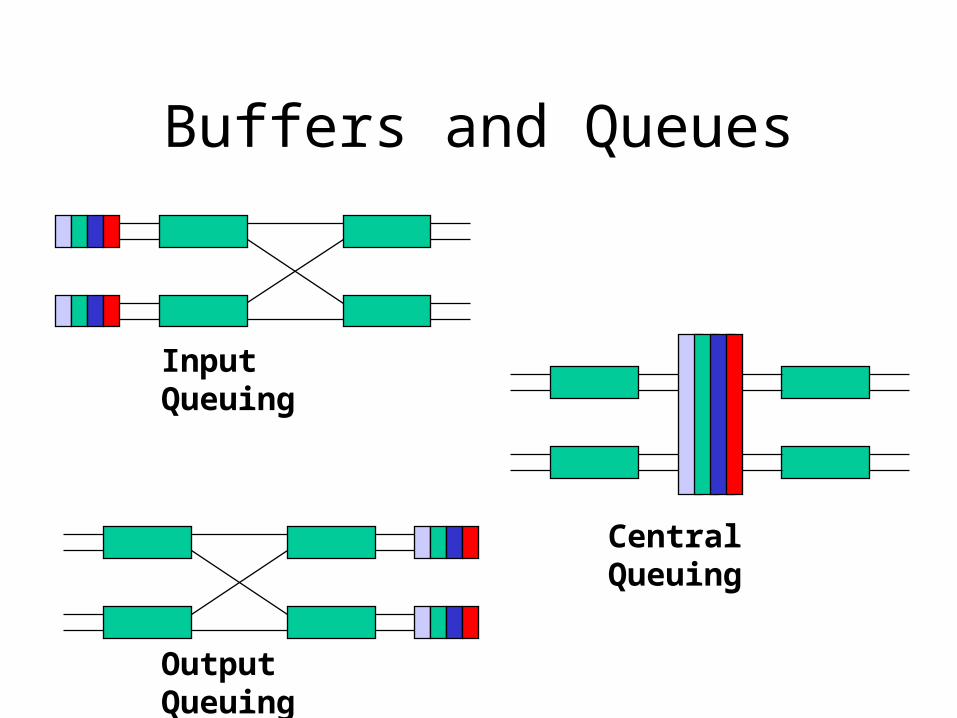
Buffers and Queues
Input Queuing
Output Queuing
Central Queuing
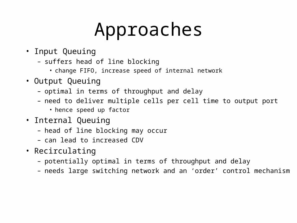
Approaches• Input Queuing
– suffers head of line blocking• change FIFO, increase speed of internal network
• Output Queuing– optimal in terms of throughput and delay– need to deliver multiple cells per cell time to output port
• hence speed up factor
• Internal Queuing– head of line blocking may occur– can lead to increased CDV
• Recirculating– potentially optimal in terms of throughput and delay– needs large switching network and an ‘order’ control mechanism
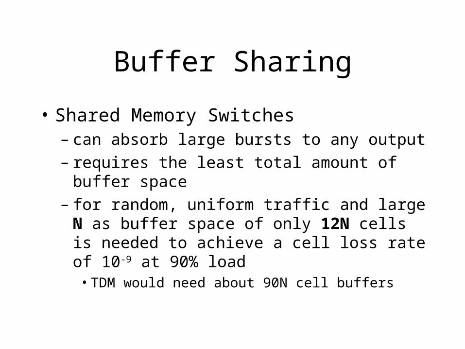
Buffer Sharing
• Shared Memory Switches– can absorb large bursts to any output– requires the least total amount of buffer space– for random, uniform traffic and large N as
buffer space of only 12N cells is needed to achieve a cell loss rate of 10-9 at 90% load
• TDM would need about 90N cell buffers
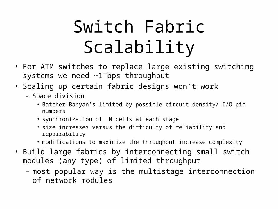
Switch Fabric Scalability
• For ATM switches to replace large existing switching systems we need ~1Tbps throughput
• Scaling up certain fabric designs won’t work– Space division
• Batcher-Banyan’s limited by possible circuit density/ I/O pin numbers
• synchronization of N cells at each stage
• size increases versus the difficulty of reliability and repairability
• modifications to maximize the throughput increase complexity
• Build large fabrics by interconnecting small switch modules (any type) of limited throughput
– most popular way is the multistage interconnection of network modules
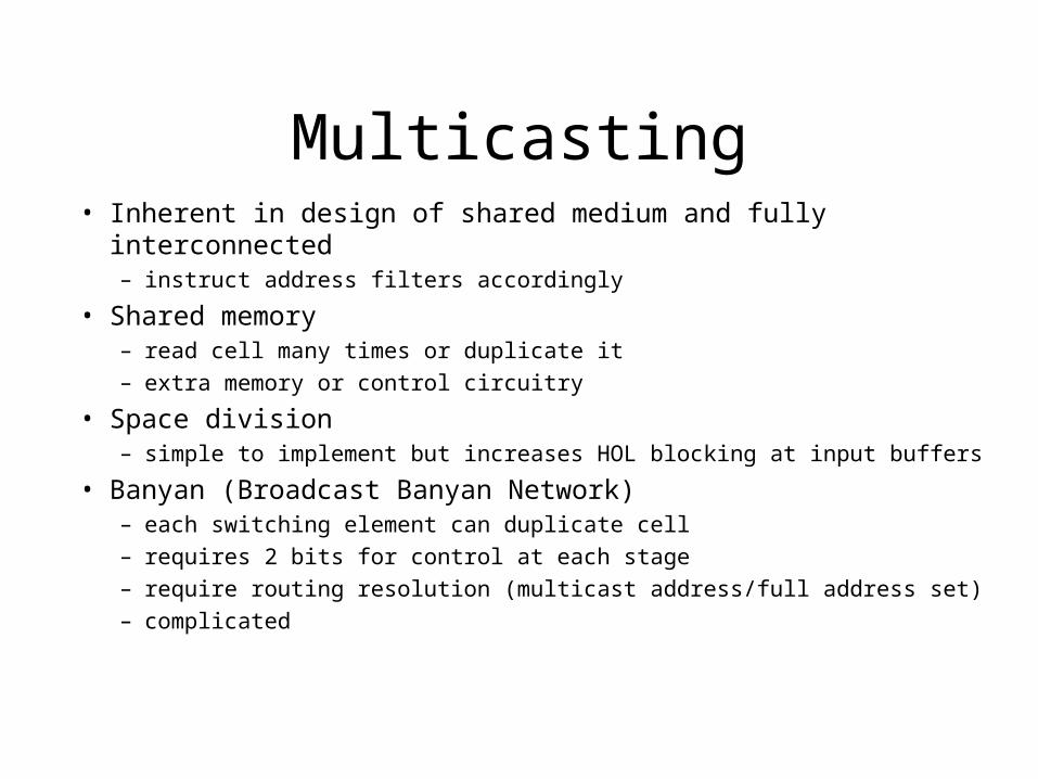
Multicasting• Inherent in design of shared medium and fully interconnected
– instruct address filters accordingly
• Shared memory– read cell many times or duplicate it– extra memory or control circuitry
• Space division– simple to implement but increases HOL blocking at input buffers
• Banyan (Broadcast Banyan Network)– each switching element can duplicate cell– requires 2 bits for control at each stage– require routing resolution (multicast address/full address set)– complicated
System Management
• System Management– Physical + ATM layer OAM
– Switch resource usage measurement
– MIB + NM
• Supervise and coordinate all NM activities
• Collect and administer management info– MIB
• Communicate with users and Net managers– SNMP, CMIP
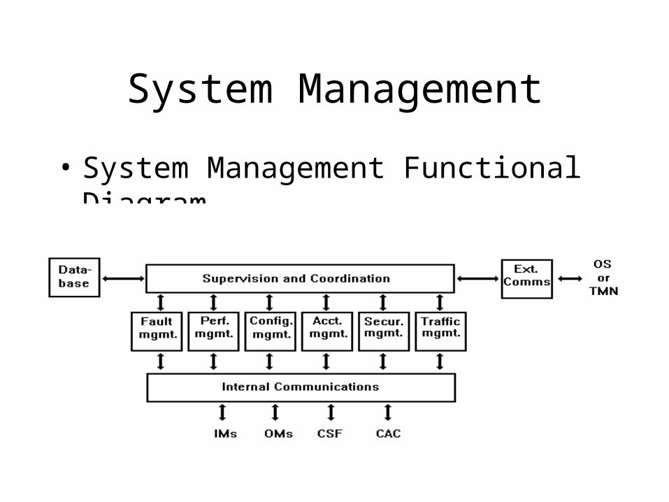
System Management
• System Management Functional Diagram
Fault
• Physical Layer [e.g. SONET]
– Loss of: SIGNAL, FRAME, POINTER, SYNC
– SONET management info (APS…)
– SM determines actions
• ATM layer– IM may extract/copy fault management cells
– SM may generate outgoing OAM cells [->OM]
Traffic
• Congestion monitoring and control– Notify NM to control manually– Discard - CLP– Reroute– CSF Internal flow control– Reconfigure CSF– Adjust UPC/NPC (Usage/Network Parameter
Control)
Where to get more information
• ATM Switching Systems, Chen and Liu 1995, Artech House [621.382]
• Web Search on ATM+Switches
• eg. http:/design-net.com/solutions/wired/atm/fabric.html
• Emerging Communications Technologies, Black, 1994, Prentice Hall
• Halsall 4th edition
• Stallings 5th edition


