Page | 1 REPORT ON THEORITICAL ANALYSIS ON A FBC(A TMOSPH ERIC FLUIDIZED BED COMBUSTION) BOILER Submitted by CHHATRAVALA AMIT A. (080160119013) BARAIYA RAMESH P. (090163119002) SANGANI JAYVANT B. (090163119101) In fulfil lment for th e award of th e degree ofBACHELOR OF ENGINEERING In MECHANICAL GOVERNMENT ENGINEERING COLLEGE MODASA Gujarat Technological University, Ahmedabad December, 2011 Government Engineering College Modasa Mechanical Engineering Department 2012
Transcript
7/27/2019 ATMOSPHERIC FLUIDIZED BED COMBUSTION BOILER
In developing economy that is ours, development inputs remain constant demand
necessitating use of resources. Electric by virtue of its being the most convenient form of inputs,has proved to be one of the most powerful vehicles for promoting economic well being of the
society through industrial growth.
Electric power has thus come to be considered as the most important input in the nation’s
endeavors towards industrialization as well as in attaining the growth rate that our development
plans aim to achieve. It is thus only natural that the per capita of electricity has come to be
considered as a measure of the country’s industrial accomplishment as also the standard of living
of the society.
The country has made tremendous progress in the field of electric power in the past three
decades. The installed capacity has steadily increased to 45000 MW. From this generation was
from coal fired power plant.
Indian has reserves of the order of 13000 million tones/ much of reserves is not of high
quality and contains appreciable amount of incombustible matter. It is only rational to utilize
these large reserves of coal by converting this primary source of energy to process and more
concentrated forms, which makes it easy for transportation and use. Conversion of electric power
is one such processing on which the country has rightly placed the emphasis upon.
Chapter 1
7/27/2019 ATMOSPHERIC FLUIDIZED BED COMBUSTION BOILER
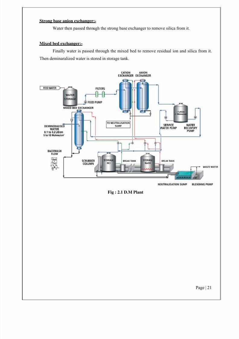
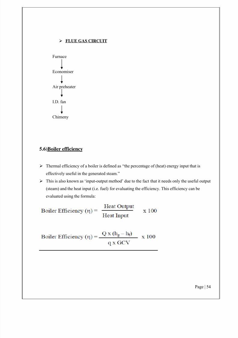
This section briefly describes the Boiler and various auxiliaries in the Boiler Room.
A boiler is an enclosed vessel that provides a means for combustion heat to be transferred to water until it becomes heated water or steam. The hot water or steam under pressure is then
usable for transferring the heat to a process. Water is a useful and inexpensive medium for
transferring heat to a process. When water at atmospheric pressure is boiled into steam its volume
increases about 1,600 times, producing a force that is almost as explosive as gunpowder. This
causes the boiler to be an equipment that must be treated with utmost care.
The boiler system comprises of: a feed water system, steam system and fuel system. The
feed water system provides water to the boiler and regulates it automatically to meet the steam
demand. Various valves provide access for maintenance and repair. The steam system collects
and controls the steam produced in the boiler. Steam is directed through a piping system to the
point of use. Throughout the system, steam pressure is regulated using valves and checked with
steam pressure gauges. The fuel system includes all equipment used to provide fuel to generate
the necessary heat. The equipment required in the fuel system depends on the type of fuel used in
the system.
The water supplied to the boiler that is converted into steam is called feed water. The two
sources of feed water are: (1) Condensate or condensed steam returned from the processes and (2)
Makeup water (treated raw water) which must come from outside the boiler room and plant
processes. For higher boiler efficiencies, an economizer preheats the feed water using the waste
heat in the flue gas.
1.1) OVERVIEW OF THE PLANT
7/27/2019 ATMOSPHERIC FLUIDIZED BED COMBUSTION BOILER
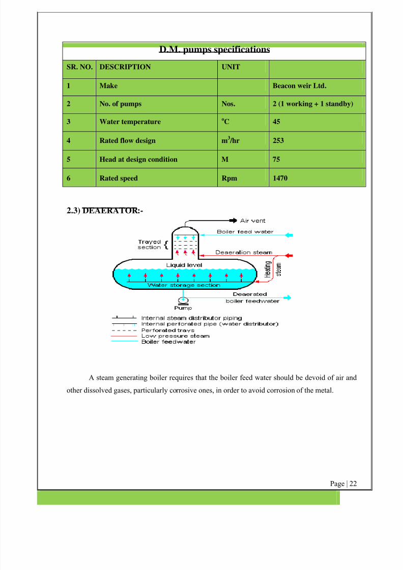
Generally, power stations use a deaerator to provide for the removal of air and other
dissolved gases from the boiler feedwater. A deaerator typically includes a vertical, domed
deaeration section mounted on top of a horizontal cylindrical vessel which serves as the deaerated
boiler feedwater storage tank.
There are many different designs for a deaerator and the designs will vary from onemanufacturer to another. The adjacent diagram depicts a typical conventional trayed deaerator. If
operated properly, most deaerator manufacturers will guarantee that oxygen in the deaerated
water will not exceed 7 ppb by weight (0.005 cm³/L).
7/27/2019 ATMOSPHERIC FLUIDIZED BED COMBUSTION BOILER
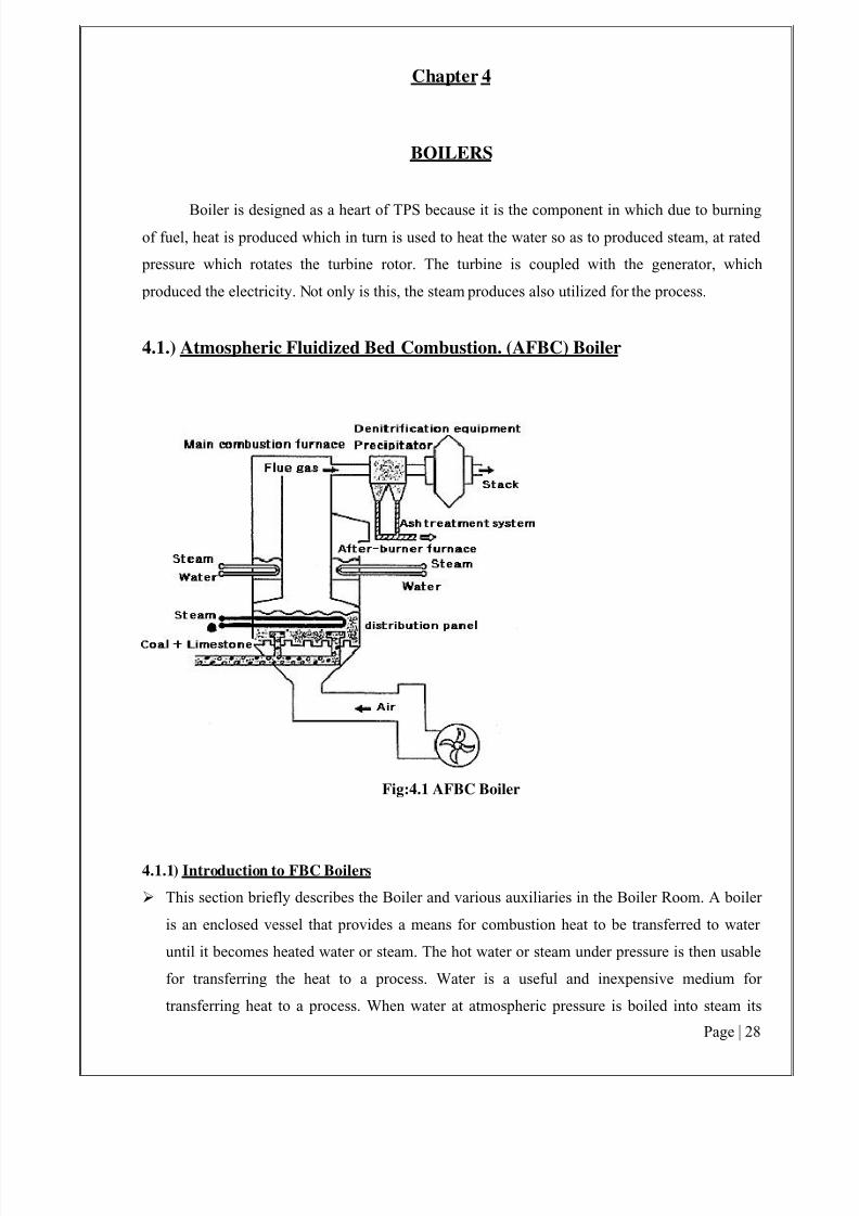
Boiler is designed as a heart of TPS because it is the component in which due to burningof fuel, heat is produced which in turn is used to heat the water so as to produced steam, at rated
pressure which rotates the turbine rotor. The turbine is coupled with the generator, which
produced the electricity. Not only is this, the steam produces also utilized for the process.
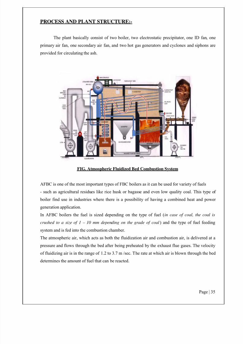
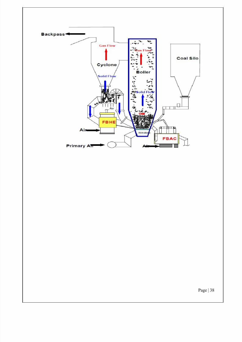
4.1.) Atmospheric Fluidized Bed Combustion. (AFBC) Boiler
Fig:4.1 AFBC Boiler
4.1.1) Introduction to FBC Boilers
This section briefly describes the Boiler and various auxiliaries in the Boiler Room. A boiler
is an enclosed vessel that provides a means for combustion heat to be transferred to water
until it becomes heated water or steam. The hot water or steam under pressure is then usable
for transferring the heat to a process. Water is a useful and inexpensive medium for
transferring heat to a process. When water at atmospheric pressure is boiled into steam its
7/27/2019 ATMOSPHERIC FLUIDIZED BED COMBUSTION BOILER
volume increases about 1,600 times, producing a force that is almost as explosive as
gunpowder. This causes the boiler to be an equipment that must be treated with utmost care.
The boiler system comprises of: a feed water system, steam system and fuel system. The
feed water system provides water to the boiler and regulates it automatically to meet the steam
demand. Various valves provide access for maintenance and repair. The steam system collectsand controls the steam produced in the boiler. Steam is directed through a piping system to the
point of use. Throughout the system, steam pressure is regulated using valves and checked
with steam pressure gauges. The fuel system includes all equipment used to provide fuel to
generate the necessary heat. The equipment required in the fuel system depends on the type of
fuel used in the system.
The water supplied to the boiler that is converted into steam is called feed water. The two
sources of feed water are: (1) Condensate or condensed steam returned from the processes and
(2) Makeup water (treated raw water) which must come from outside the boiler room and
plant processes. For higher boiler efficiencies, an economizer preheats the feed water using
the waste heat in the flue gas.
7/27/2019 ATMOSPHERIC FLUIDIZED BED COMBUSTION BOILER
The traditional grate fuel firing systems have several limitations and hence are techno
economically unviable to meet the challenges of the future. FBC has emerged as a viable
alternative as it has significant advantages over conventional firing system. FBC offers multiple
benefits, such as: compact boiler design, flexibility with fuel used, higher combustion efficiency
and reduced emissions of noxious pollutants such as SOx and NOx. The fuels burnt in these
boilers include coal, washery rejects, rice husk, bagasse and other agricultural wastes. Thefluidized bed boilers have a wide capacity range- 0.5 T/hr to over 100 T/hr.
7/27/2019 ATMOSPHERIC FLUIDIZED BED COMBUSTION BOILER
When an evenly distributed air or gas is passed upward through a finely divided bed of
solid particles such as sand supported on a fine mesh, the particles remain undisturbed at low
velocities. As the air velocity is gradually increased, a stage is reached when the individual
particles are suspended in the air stream and the bed is called “ fluidized ”. With further increase inair velocity, there is bubble formation, vigorous turbulence, rapid mixing and formation of dense
defined bed surface. The bed of solid
particles exhibits the properties of a boiling liquid and assumes the appearance of a fluid –
“bubbling fluidized bed”. At higher velocities, bubbles disappear, and particles are blown out of
the bed. Therefore, some amounts of particles have to be re-circulated to maintain a stable system
and is called as “Atmospheric fluidized bed ". This principle of fluidization is illustrated in Figure.
Fig:4.2 Mechanism of FBC Boiler
7/27/2019 ATMOSPHERIC FLUIDIZED BED COMBUSTION BOILER
Fluidization depends largely on the particle size and the air velocity. The mean solids
velocity increases at a slower rate than does the gas velocity. The difference between the mean
solid velocity and mean gas velocity is called as slip velocity.
Maximum slip velocity between the solids and the gas is desirable for good heat transfer
and intimate contact. If sand particles in fluidized state are heated to the ignition temperatures of fuel (rice husk, coal or bagasse), and fuel is injected continuously into the bed, the fuel will burn
rapidly and the bed attains a uniform temperature.
The fluidized bed combustion (FBC) takes place at about 840°C to 950°C. Since this
temperature is much below the ash fusion temperature, melting of ash and associated problems
are avoided. The lower combustion temperature is achieved because of high coefficient of heat
transfer due to rapid mixing in the fluidized bed and effective extraction of heat from the bed
through in-bed heat transfer tubes and walls of the bed. The gas velocity is maintained between
minimum fluidization velocity and particle entrainment velocity. This ensures a stable operation
of the bed and avoids particle entrainment in the gas stream.
Any combustion process requires three “T”s - that is Time, Temperature and Turbulence.
In FBC, turbulence is promoted by fluidization. Improved mixing generates evenly distributed
heat at lower temperature. Residence time is many times higher than conventional grate firing.
Thus an FBC system releases heat more efficiently at lower temperatures. Since limestone can
also be used as particle bed (in case the fuel with sulphur content is used), control of SOx and
NOx emissions in the combustion chamber is achieved without any additional control equipment.
This is one of the major advantages over conventional boilers.
7/27/2019 ATMOSPHERIC FLUIDIZED BED COMBUSTION BOILER
Historically, boilers were a source of many serious injuries and property destruction due to
poorly understood engineering principles. Thin and brittle metal shells can rupture, while poorly
welded or riveted seams could open up, leading to a violent eruption of the pressurized steam.
Collapsed or dislodged boiler tubes could also spray scalding-hot steam and smoke out of the air
intake and firing chute, injuring the firemen who loaded coal into the fire chamber. Extremely
large boilers providing hundreds of horsepower to operate factories could demolish entire
buildings.
A boiler that has a loss of feed water and is permitted to boil dry can be extremely
dangerous. If feed water is then sent into the empty boiler, the small cascade of incoming water
instantly boils on contact with the superheated metal shell and leads to a violent explosion thatcannot be controlled even by safety steam valves. Draining of the boiler could also occur if a leak
occurred in the steam supply lines that was larger than the make-up water supply could replace.
The Hartford Loop was invented in 1919 by the Hartford Steam Boiler and Insurance Company
as a method to help prevent this condition from occurring, and thereby reduce their insurance
claims.
7/27/2019 ATMOSPHERIC FLUIDIZED BED COMBUSTION BOILER
It is used to relieve pressure and prevent possible explosion of a boiler.
2.) Pressure gauge:
Function: To record the steam pressure at which the steam is generated in the boiler. A
bourden pressure gauge in its simplest form consists of elliptical elastic tube bent into an arc. This bent up tube is called as BOURDEN’S tube. One end of tube gauge is fixed and connected to the
steam space in the boiler. The other end is connected to a sector through a link.
3.) Fusible plug:
Function: To extinguish fire in the event of water level in the boiler shell falling below a
certain specified limit. It protects fire tubes from burning when the level of the water in the water
shell falls abnormally low and the fire tube or crown plate which is normally submerged in the
water, gets exposed to steam space which may not be able to keep it cool. It is installed below
boiler's water level. When the water level in the shell falls below the top of the plug, the steam
cannot keep it cool and the fusible metal melts due to over heating. Thus the copper plug drops
down and is held within the gunmetal body by the ribs. Thus the steam space gets communicated
to the firebox and extinguishes the fire. Thus damage to fire box which could burn up is avoided.
By removing the gun metal plug and copper plug the fusible plug can be put in position again by
interposing the fusible metal usually lead or a metal alloy.
4.) Steam stop valve
A valve is a device that regulates the flow of a fluid (gases, fluidized solids, slurries, or
liquids) by opening, closing, or partially obstructing various passageways
Function: to shut off or regulate the flow of steam from the boiler to the steam pipe or
steam from the steam pipe to the engine. When the hand wheel is turned, the spindle which is
screwed through the nut is raised or lowered depending upon the sense of rotation of wheel. The
passage for flow of steam is set on opening of the valve.
5.) Feed check valve:
i) To allow the feed water to pass into the boiler.
ii) To prevent the back flow of water from the boiler in the event of the failure of the feed
pump.
7/27/2019 ATMOSPHERIC FLUIDIZED BED COMBUSTION BOILER
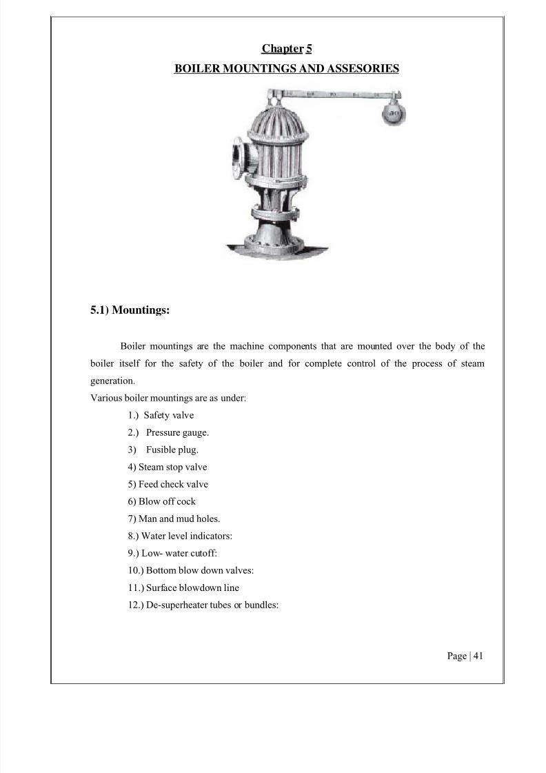
Boiler accessories are those components which are installed either inside or outside the
boiler to increase the efficiency of the plant and to help in the proper working of the plant.
Various boiler accessories are:
1) Air Preheater
2) Economizer
3) Superheater
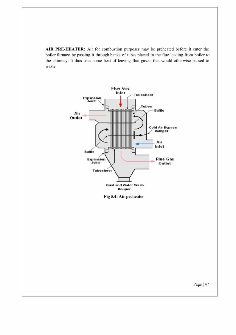
1. Air preheater:
Waste heat recovery device in which the air to on its way to the furnace is heated utilizing
the heat of exhaust gases
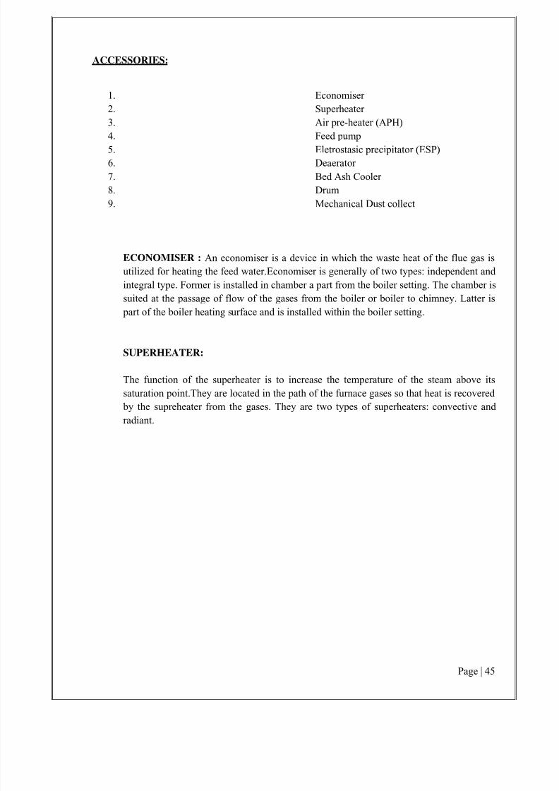
2. Economiser:
Function: To recover some of the heat being carried over by exhaust gases (This heat is
used to raise the temperature of feed water supplied to the boiler.
3. Superheater :
To superheat the steam generated by boiler Super heaters are heat exchangers in which
heat is transferred to the saturated steam to increase its temperature.
Fossil fuel power plants can have a superheater and/or reheater section in the steamgenerating furnace. Nuclear-powered steam plants do not have such sections but produce steam at
essentially saturated conditions. In a fossil fuel plant, after the steam is conditioned by the drying
equipment inside the steam drum, it is piped from the upper drum area into tubes inside an area of
the furnace known as the superheater, which has
an elaborate set up of tubing where the steam vapor picks up more energy from hot flue gases
outside the tubing and its temperature is now superheated above the saturation temperature. The
superheated steam is then piped through the main steam lines to the valves before the high pressure turbine.
7/27/2019 ATMOSPHERIC FLUIDIZED BED COMBUSTION BOILER
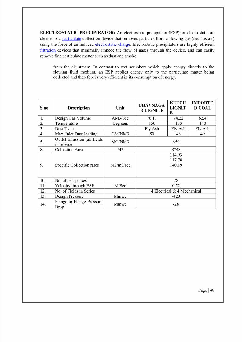
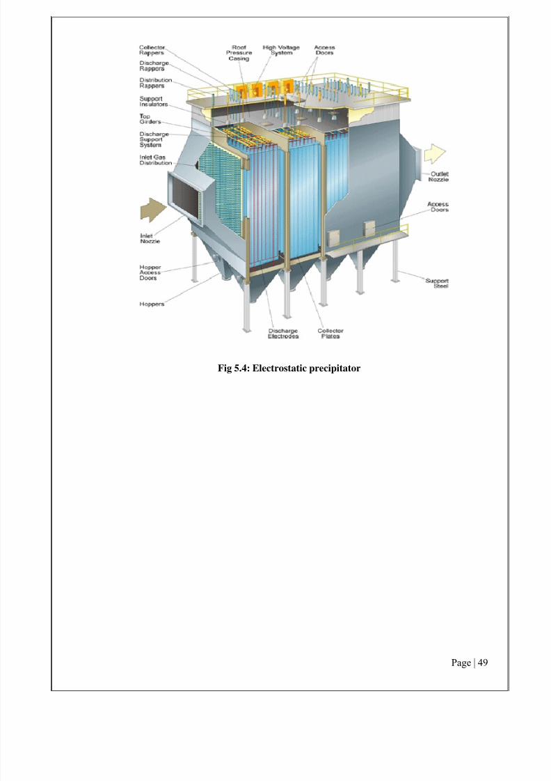
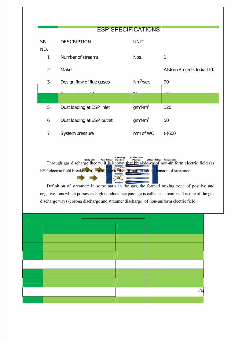
ELECTROSTATIC PRECIPIRATOR: An electrostatic precipitator (ESP), or electrostatic air
cleaner is a particulate collection device that removes particles from a flowing gas (such as air)
using the force of an induced electrostatic charge. Electrostatic precipitators are highly efficient
filtration devices that minimally impede the flow of gases through the device, and can easily
remove fine particulate matter such as dust and smoke
from the air stream. In contrast to wet scrubbers which apply energy directly to theflowing fluid medium, an ESP applies energy only to the particulate matter beingcollected and therefore is very efficient in its consumption of energy.
S.no Description UnitBHAVNAGA
R LIGNITE
KUTCH
LIGNIT
E
IMPORTE
D COAL
1. Design Gas Volume AM3/Sec 76.11 74.22 62.42. Temperature Deg cen. 150 150 1403. Dust Type Fly Ash Fly Ash Fly Ash4. Max. Inlet Dust loading GM/NM3 50 48 49
5.Outlet Emission (all fieldsin service)
MG/NM3 <50
8. Collection Area M3 8748
9. Specific Collection rates M2/m3/sec
114.93117.78140.19
10. No. of Gas passes 2811. Velocity through ESP M/Sec 0.5212. No. of Fields in Series 4 Electrical & 4 Mechanical13. Design Pressure Mmwc -420
14.Flange to Flange PressureDrop
Mmwc -28
7/27/2019 ATMOSPHERIC FLUIDIZED BED COMBUSTION BOILER
is at the corona outer region and forms even more extricated electron avalanche(no Cause of
streamer formation: Normal negative corona is electron-avalanche-like extrication in corona zone.
However when the bared voltage of the ESP electric fields rises continually, the photon will be
discharged at the electron avalanche head as a result of the compounding of the positive and
negative ions or that the excitonic atom regains normal state. The generated electron extricated by
photon is entitled as photoelectron, which longer extricate through the high field intensity of thesharp electrode, while extricate through photoelectron), this even more extricated electron
avalanche converges with the avalanche head of the main electron avalanche and in some parts of
the gas of corona outer region forms mixing zone with high conductance of positive and negative
ions. The mixing zone is called as streamer. After streamer forms, by the effect of basic electric
field, the charges in streamer section are to part and go ahead the both ends of the section, hence
to weaken electric field in the streamer. Thus, although streamer occurs at the edge of the corona
zone, the potential from it to opposite electrode is almost the same with that to the sharp
electrode, because the interior electric field intensity of streamer is very weak (i.e. streamer
obtains the ability to transmit potential), which is equivalent to that the sharp electrode extends
forward and makes extrication develop at the depth of the electric field gap (corona outer region)
and results in breakdown (spark.) Thus, the breakdown course of ESP electric fields is finished in
three segments, i.e., corona zone electron avalanche (corona)-corona outer
region streamer-electric field breakdown. Therefore the formation of streamer is premonition of
electric field breakdown; it is also acceptable to say that the streamer formation is the sufficient
condition of electric field breakdown. As for conven- tional ESP with single zone and negative
corona, this kind of pre-breakdown streamer is unfavorable, in respect that streamer will speed up
discharge development and make breakdown voltage decrease. What is more important, streamer
formation makes cation
and positive dust charged by cation appear in corona outer region (in the streamer, the
appearance of cation at corona outer region will enhance DE ionization making the corona current
increase, streamer tend to develop and breakdown voltage fall. At the same time, as for the dust,
cation reduces the charge capacity of negatively charged
dust and even charges the dust positively to make positive corpuscles form at corona outer region
of the electric fields.) Whereas ESP with single zone and negative corona can not collect positive
7/27/2019 ATMOSPHERIC FLUIDIZED BED COMBUSTION BOILER
corpuscle dust charged by the cation in the streamer, therefore dust leakage rate increases, the
deposited dust layer on the corona wire will become thick, which brings the ESP operation
exacerbation.
At corona outer region of conventional ESP, cation and positive corpuscle dust charged by
cation also exist. One of the sources is before electric field breakdown gas discharges and forms
streamer, which is the mixing zone of the positive and negative ions. Its second source is cationand positive corpuscle dust charged by cation formed because of back corona. Its third source is
the carbon in the dust with much fly ash combustible substance, which tends to be charged
positively and form cation and positive corpuscle dust charged by cation. Since the cation and
positive corpuscle dust charged by cation exist at corona outer region, then these ions and dust
must have an escape hatch, therefore a sort of structure needs to be designed to collect them.
It is common knowledge that dust charge requires high corona current in the electric field,
while collection of charged dust requires high field intensity but not high current. Thereby, charge
and dust collection is contradictory at the corona current aspect. Especially for collection of high
specific resistance dust, too high current will give birth to highelectric field on the collected dust
layer and cones- quently result in dust layer gap breakdown, back corona and dust removal
efficiency drop. As against double-zone ESP, the charge zone and dust collection zone of the
double-zone electric field are structurally completely separated and is able to be intensified
respectively.
Through variant wire-plate tests, Longking has developed a new model of double-zone ESP -
mechanical and electronic multiplex double-zone ESP (hereinafter referred to as double- zone
ESP.). It is composed of charge zone structure of the conventional needle bared wire & flat plate
type BE plate and the dust collection zone structure of tube type auxiliary electrode & flat plate
type BE plate. These two structures is configured alternatively, each of which is energized by
independent power supply. Thus, charge and dust collection functions are intensified respectively
and forms a sort of mechanical and electronic multiplex structure. In no-load electric pressure
build-up test, no spark over appears in the fields composed of tube type auxiliary electrode and
flat
plate type BE plate with the gas passage spacing of 400 mm, when the electric field intensity
reach 4.2 kV/cm. During actual operation, its secondary voltage is able to reach 80 kV in general,
which intensifies enormously dust collection function.
7/27/2019 ATMOSPHERIC FLUIDIZED BED COMBUSTION BOILER
The charge zone and collection zone of the double-zone ESP are energized separately by
independent HV power supply. The charge zone employs power supply according to conventional
plate current density. However, since in the collection zone the on-site operation voltage is very
high and the current is very low, when the gas passage spacing is 400mm, the voltage is chosen as80 kV. For the dust with not too high specific resistance, 90 kV level can be chosen; the plate
current density is general between 0.05 mA-0.08 mA/m2. Compared to conventional ESP fro
300MW unit, to reach the same dust removal efficiency, the double ESP can save 15%-18%
electricity consumption.
In double-zone electric fields, the wire-plate form of the charge zone is almost the same with
the conventional electric fields, which not only charges the dust, but also collect the negatively
charged dust. The collection zone is composed of the tube type auxiliary electrodes and ordinary
plate type CE plates, which possesses characteristics of high electric voltage, low current and
more uniform plate current density distribution.
The industrial application results show when collecting coal burnt boiler dust, the double-zone
ESP can be adaptable to comparatively wide scale of coal without back corona in the dust
collection zone and with more stable operation. Besides the dust removal efficiency, dust
migration speed and value-cost ratio are all higher than the conventional horizontal ESP. The last
but not the least, it can reduce the flue dust emission concentration below 50 mg/DNm3 thereby
to reduce the fine dust emission, which is favorable to protect atmosphere environment and
human health.
7/27/2019 ATMOSPHERIC FLUIDIZED BED COMBUSTION BOILER
A) Two-stage particle separation system1. Greater than 99.8% particle collection efficiency2. Provides a means to control particle size distribution in furnace, which results in
improved carbon burnout, limestoneutilization, emissions and heat transfer 3. Reduces operating costs
B) All-internal primary solids recirculation(U- beam)1. Compact design requires 20-30% less building volume thancyclone-based CFBC
boilers — critical for repowering projects2. Lowers auxiliary power consumption compared with cyclone-based CFBC boilers
C) Low, uniform velocities at the furnace exitU-beam separators, and the super heater 1. Significantly reduces erosion in upper furnace andsuper heater compared with
cyclone designs2. To date, no U-beam erosion maintenance required in anyIR-CFBC unit3. No high-maintenance vortex fi nders or hot expansion joints;therefore, no
maintenance expenses for these items
D) No thick refractory due to elimination of hotcyclones and hot return legs1. Thin, cooled refractory places no restriction on boiler start-upor shut–down rate2. Significantly reduces need for refractory maintenance3. Virtually eliminates forced outages due to refractory failures4. Requires only 10 to 25% of the total refractory comparedwith hot cyclone CFBC
designsE) In-furnace heat transfer surface
1. Vertical, flat membraned tube panels within furnace performevaporative or superheat duty
2. Proven reliability and low maintenanceF) Unique primary air nozzles (bubble caps)
1. Reduces back sifting of solids during low-load operation
2. Reduces need for periodic cleaning of nozzles and primary airwindbox3. Minimises erosion inside nozzle caused by the re-entrainmentof back-sifted solids
G) Soot blowers not required upstream of MDC1. Eliminates steam consumption, maintenance costs and forcedoutages typically
associated with sootblowersH) Gravity fuel feed and fl y ash recycle system
1. Reduces maintenance, forced outages and auxiliary powerrequirements byeliminating the mechanical fuel injection andpneumatic fl y ash recycle systems
I) High turndown (up to 5:1) without auxiliary fuelsupport1. Allows wider load swings2. Reduces operating costs (no auxiliary fuel) during low–loadoperation
7/27/2019 ATMOSPHERIC FLUIDIZED BED COMBUSTION BOILER