All rights reserved including the right of reproduction in whole or in part in any form. This document may be electronically reproduced, distributed, or printed in its entirety provided this copyright and statement are attached. Any modification or any other reproduction, distribution, or use of this document or portions hereof is strictly prohibited without the express written permission of Varian, Inc.
COPYRIGHT 2006 All rights reserved.
Quality Systems At Varian, Inc. The ISO 9000 series standards were created in Geneva in 1987 to cut through a morass of conflicting
quality definitions. These standards define a model for quality assurance systems in product design, development, manufacturing, installation, service, and customer support. They are now the worldwide quality assurance benchmark used to gauge the strength of a company's commitment to quality, and the value of its quality systems.
Various organizations around the world, such as the British Standards Institution (BSI), provide certified, objective auditors to scrutinize quality procedures, product development, manufacturing processes, and customer satisfaction programs. No company can claim ISO 9000 series registration unless it receives a stamp of approval from the demanding quality assessors of BSI or similar accredited examining body. ISO 9000 series registration constitutes an objective third-party report to determine the level of a supplier's commitment to quality.
In 1992, Varian, Inc., Analytical Instruments became registered to the most comprehensive of the ISO 9000 series standards — ISO 9001. ISO 9001 registration means that every stage of our quality system, including product development, manufacturing, final test, shipping, and parts and supplies has been rigorously examined against the most exacting set of internationally recognized standards. It means we live up to a standard of quality that you can count on today, and into the future. Our Quality System has received ISO 9001 certification number FM21797.
The quality systems that earned us ISO 9001 registration have direct benefits for our customers:
♦ We can speed instruments to you faster than ever before. Emergency orders can be processed even faster.
♦ We fill your orders promptly and completely.
♦ We have implemented a system of continuous feedback from our customers — we are aware of your needs today and tomorrow.
♦ We have improved your productivity by cutting systems failure rates in half and speeding service response time.
♦ We have embedded continuous improvement into the fabric of our organization so that we can achieve even higher levels of quality in the future.
♦ We are embedding GLP requirements into our products and services to help you meet your regulatory compliance requirements.
ISO 9001 registration is not enough. For us, quality is defined by our customers. We are not satisfied unless you are satisfied. We are striving to understand customer needs, using independent surveys, user groups, customer advisory boards, and our “Hallmark of Quality” response program, in addition to individual face-to-face customer contact. Our products and our processes are configured to meet those needs. We know that you are seeking more than the most advanced processes and top-notch applications expertise. You want to join forces with a partner committed to delivering world-class quality, reliability, and value — on time, every time.
Our overriding aim is to be that partner.
03-914451-00:4 1 of 1
Varian, Inc. Analytical Instrument Warranty
Hardware Products All analytical instruments sold by Varian, Inc. are warranted to be free from defects in material and workmanship for the periods specified and in accordance with the terms on the face of Varian's quotation or as otherwise agreed upon in writing between Varian and the Customer. The warranty period begins on the date of shipment from Varian to the original Customer. However, where installation is paid for by the Customer or included in the purchase price, the warranty period begins upon completion of installation. If the Customer schedules installation to start later than 30 days after delivery or if such delay is caused through the Customer's inability to provide adequate facilities or utilities or through failure to comply with Varian's reasonable pre-installation instructions or through other omissions by Customer, then the warranty period starts on the 31st day from date of shipment. Moreover Varian will charge the Customer for labor and other expenses involved in making multiple or follow-up installation service calls.
Software Products Where software is provided within the frame of a license agreement concluded between the Customer and Varian, any warranty shall be strictly in accordance with the terms of such agreement.
In the absence of a license agreement and unless an alternate warranty period is agreed upon in writing between Varian and the Customer, the warranty period is as specified on the face of Varian's quotation. Varian warrants such software products, if used with and properly installed on Varian hardware or other hardware as specified by Varian to perform as described in the accompanying Operator's Manual and to be substantially free of those defects which cause failure to execute respective programming instructions; however, Varian does not warrant uninterrupted or error-free operation.
Remedies The sole and exclusive remedy under hardware warranty shall be repair of instrument malfunctions which in Varian's opinion are due or traceable to defects in original materials or workmanship or, at Varian's option, replacement of the respective defective parts, provided that Varian may as an alternative elect to refund an equitable portion of the purchase price of the instrument or accessory.
Repair or replacement under warranty does not extend the original warranty period.
Repair or replacement under warranty claims shall be made in Varian's sole discretion either by sending a Customer Support Representative to the site or by authorizing the Customer to return the defective accessory or instrument to Varian or to send it to a designated service facility. The Customer shall be responsible for loss or damage in transit and shall prepay shipping cost. Varian will return the accessory or instrument to the Customer prepaid and insured. Claims for loss or damage in transit shall be filed by the Customer. To correct software operation anomalies, Varian will issue software revisions where such revisions exist and where, in Varian's opinion, this is the most efficient remedy.
Limitation of Warranty This warranty does not cover software supplied by the Customer, equipment and software warranted by another manufacturer or replacement of expendable items and those of limited life, such as but not limited to: Filters, glassware, instrument status lamps, source lamps, septa, columns, fuses, chart paper and ink, nebulizers, flow cells, pistons, seals, fittings, valves, burners, sample tubes, probe inserts, print heads, glass lined tubing, pipe and tube fittings, variable temperature dewars, transfer lines, flexible discs, magnetic tape cassettes, electron multipliers, filaments, vacuum gaskets, seats and all parts exposed to samples and mobile phases.
This warranty shall be void in the event of accident, abuse, alteration, misuse, neglect, breakage, improper operation or maintenance, unauthorized or improper modifications or tampering, use in an unsuitable physical environment, use with a marginal power supply or use with other inadequate facilities or utilities. Reasonable care must be used to avoid hazards.
This warranty is expressly in lieu of and excludes all other express or implied warranties, including but not limited to warranties of merchantability and of fitness for particular purpose, use or application, and all other obligations or liabilities on the part of Varian, unless such other warranties, obligations or liabilities are expressly agreed to in writing by Varian.
Limitation of Remedies and Liability The remedies provided herein are the sole and exclusive remedies of the Customer. In no case will Varian be liable for incidental or consequential damages, loss of use, loss of production or any other loss incurred.
03-914412-00:2 1 of 1
Qualitätssysteme bei Varian, Inc. Die Standards der ISO 9000 Serien wurden 1987 in Genf mit dem Ziel geschaffen, das Durch-
einander gegensätzlicher Qualitätsbestimmungen zu entwirren. Diese Standards legen ein Modell für Qualitätssicherungssysteme hinsichtlich Produktdesign, Entwicklung, Herstellung, Installation, Service und Kundenbetreuung fest. Sie sind nun die weltweiten Maßstäbe der Qualitätssicherung, die die An-strengungen eines Unternehmens bezüglich der Qualität und der Bedeutung seiner Qualitätssysteme mes-sen.
Verschiedene Organisationen in der ganzen Welt, wie die British Standards Institution (BSI), stel-len ausgebildete, objektive Prüfer zur Begutachtung von Qualitätsmaßnahmen, Produktentwicklung, Her-stellungsprozessen und von Programmen zur Erforschung der Kundenzufriedenheit zur Verfügung. Kein Unternehmen kann die ISO 9000 Registrierung beantragen, ohne die Genehmigung von den beauftragten Qualitätsgutachtern der BSI oder einer ähnlichen akkreditierten Stelle erhalten zu haben. Die ISO 9000 Registrierung bildet einen objektiven Bericht von dritter Seite, um den Grad der Qualitätsanstrengung eines Lieferanten zu bestimmen.
1992 wurden die Varian, Inc., Analytical Instruments nach den umfassendsten Standards der ISO 9000 Serie registriert — ISO 9001. Die ISO 9001 Registrierung bedeutet, daß jedes Stadium unseres Qualitätssystems, einschließlich Produktentwicklung, Herstellung, Endkontrolle, Versand, sowie Teile und Zubehör rigoros gegen die anspruchsvollste Serie international anerkannter Standards geprüft worden ist. Das bedeutet, daß wir einen Qualitätsstandard bieten, auf den Sie heute und in Zukunft rechnen kön-nen. Unser Qualitätssystem hat die ISO 9001 Zertifikatnummer FM21797 erhalten.
Die Qualitätssysteme der ISO 9001 Registrierung haben für unsere Kunden direkte Vorteile:
♦ Wir können Instrumente schneller denn je zu Ihnen schicken. Eilbestellungen werden noch schneller durchgeführt.
♦ Wir erfüllen Ihre Bestellungen pünktlich und vollständig.
♦ Wir haben ein System kontinuierlichen Informationsrückflusses von unseren Kunden auf-gebaut—wir kennen Ihre Anforderungen von heute und von morgen.
♦ Wir haben Ihre Produktivität durch Halbierung der Systemfehlerraten und durch Verkür-zung unserer Reaktionszeit im Service verbessert.
♦ Wir haben kontinuierliche Verbesserungen in unserer Organisationsstruktur verankert, so daß wir künftig eine noch höhere Qualität erreichen können.
♦ Wir haben die GLP Anforderungen in unsere Produkte und Dienstleistungen eingeführt, um Ihnen bei der Erfüllung Ihres behördlichen Abnahmeprotokolls zu helfen.
Die ISO 9001 Registrierung ist nicht genug. Für uns wird Qualität durch unsere Kunden de-finiert. Wir sind nicht zufrieden, wenn Sie es nicht auch sind. Wir bemühen uns, die Anforderungen un-serer Kunden durch unabhängige Untersuchungen, Anwendergruppen, Kundenberatungsgremien und un-ser Antwortprogramm “Gütesiegel der Qualität” zu verstehen, zusätzlich zu persönlichen Kundenkontak-ten. Unsere Produkte und unsere Prozesse sind so gestaltet, daß sie diese Anforderungen erfüllen.
Wir wissen, daß Sie mehr als fortschrittliche Prozesse und ausgezeichnetes Anwendungswissen suchen. Sie suchen einen Partner, der Qualität von Weltklasse, Verläßlichkeit und Nutzen für Sie liefert— pünktlich und jederzeit.
Unser oberstes Ziel ist, für Sie dieser Partner zu sein.
03-914451-81:4 1 von 1
Varian, Inc. Analytical Instrument Garantie
Hardwareprodukte Es wird garantiert, daß alle von Varian, Inc. verkauften analytischen Instrumente für die angegebene Zeitdauer und in Übereinstimmung mit den „Allgemeinen Liefer-bedingungen“ oder anderen schriftlichen Zusagen zwischen Varian und dem Kunden frei von Material- und Herstellungsfehlern sind. Die Garantiezeit beginnt mit dem Versanddatum von Varian zum Originalkunden. Wenn die Installation vom Kunden bezahlt oder im Ver-kaufspreis eingeschlossen ist, beginnt die Garantiezeit nach der abgeschlossenen Installation. Wenn der Kunde den Installationsbeginn später als 30 Tage nach erfolgter Lieferung ansetzt, oder wenn die Verzögerung dadurch verursacht wird, daß der Kunde nicht den ausreichenden Platz oder die Ver-sorgungseinrichtungen beschafft oder Varian's berechtigte Anweisungen zur Installationsvorbereitung nicht einhält oder andere Versäumnisse des Kunden vorliegen, dann beginnt die Garantiezeit am 31. Tag nach dem Versanddatum. Darüber hinaus wird Varian dem Kunden den Arbeitsaufwand und andere Unkosten durch mehrfache oder fortgesetzte Installationsanfor-derungen berechnen.
Softwareprodukte Wo Software innerhalb des Rahmens eines Lizenz-abkommens zwischen dem Kunden und Varian geliefert wird, wird die Garantie genau entsprechend der zeitlichen Abmachung eingehalten.
Besteht kein Lizenzabkommen und ist keine alternative Garantiezeit schriftlich zwischen Varian und dem Kun-den festgelegt, gilt die Garantiezeit der „Allgemei-nen Lieferbedingungen“. Varian garantiert für solche Soft-wareprodukte, die mit Varian’s Hardware benutzt und richtig installiert sind oder zur Ausführung mit anderer von Varian angegebener Hardware, wie sie in der beige-fügten Bedienungsanleitung beschrieben ist, daß sie im wesentlichen frei von solchen Defekten sind, die Fehler bei der Ausführung der jeweiligen Programmieran-weisungen verursachen; Varian garantiert jedoch keine ununterbrochene oder fehlerfreie Arbeitsweise.
Abhilfen Die einzige und ausschließliche Abhilfe in der Hardware-garantie wird die Reparatur der Instrumentstörungen sein, die sich nach Varian's Ansicht auf Defekte in den Originalteilen oder bei der Herstellung zurückführen läßt oder, nach Varian's Wahl, der Austausch der entspre-chenden defekten Teile oder die Erstattung eines fairen Teils des Kaufpreises des Instruments oder Zubehörs, vorausgesetzt, daß sich Varian alternativ dafür entschei-det.
Reparatur oder Austausch unter Garantie verlängert nicht die ursprüngliche Garantiezeit.
Reparatur oder Austausch unter Garantieansprüchen soll in Varian's ausschließlichem Ermessen entweder durch einen Serviceingenieur beim Kunden oder durch Ermächtigung des Kunden zum Einschicken des defek-ten Zubehörs oder Instruments an Varian oder einen Servicestützpunkt erfolgen. Der Kunde übernimmt die Verantwortung für Verlust oder Beschädigung im Transit und hat die Versandkosten im voraus zu bezahlen. Var-ian wird das Zubehör oder Instrument vorausbezahlt und versichert zum Kunden zurückschicken. Ansprüche für Verlust oder Beschädigung im Transit hat der Kunde zu erheben. Zur Korrektur von Anomalien des Soft-warebetriebs wird Varian Software-Neuausgaben aus-geben, sofern Revisionen existieren und dies die beste Abhilfe ist.
Garantieeinschränkungen Diese Garantie erfaßt nicht vom Kunden bereitgestellte Software, Ausrüstungen und Software, die von anderen Herstellern garantiert werden oder den Austausch ent-behrlicher Teile und solcher von begrenzter Lebens-dauer wie diese, aber nicht darauf beschränkt: Filter, Glaswaren, Instrument Statuslampen, Lampenquellen, Septen, Säulen, Sicherungen, Schreiberpapier und Tinte, Zerstäuber, Flußzellen, Kolben, Dichtungen, Fit-tings, Ventile, Brenner, Probenröhrchen, Sondenein-sätze, Druckköpfe, glasausgekleidetes Rohr, Leitungs- und Rohrfittings, Dewars für variable Temperaturen, Transferleitungen, flexible Disketten, Magnetbandkasset-ten, elektronische Vervielfacher, Hitzdrähte, Vakuum Gaskets, Sitzflächen und alle Teile, die den Proben und mobilen Phasen ausgesetzt sind.
Diese Garantie erlischt bei eingetretenem Unfall, fal-scher Benutzung, Umbau, Mißbrauch, Vernachläs-sigung, Bruch, falscher Benutzung oder falscher War-tung, unbefugten oder falschen Modifikationen oder Basteleien, Benutzung in ungeeigneter physikalischer Umgebung, Benutzung mit marginaler Stromversorgung oder Benutzung mit anderen ungenügenden Einrichtun-gen oder Versorgungen. Mit vernünftiger Sorgfalt müssen Gefahren vermieden werden.
Diese Garantie steht ausdrücklich anstelle von allen anderen angedeuteten Garantien und schließt sie aus, einschließlich, aber nicht beschränkt auf Garan-tien der Verkäuflichkeit und Eignung für einen be-sonderen Zweck, Gebrauch oder Anwendung und allen anderen Verpflichtungen oder Haftungen von Varian’s Seite, wenn nicht solche Garantien, Verpflichtungen oder Haftungen ausdrücklich schriftlich mit Varian vereinbart wurden.
Beschränkung der Hilfen und Haftung Die hier gegebenen Hilfen sind einzig und allein Sa-che des Kunden. In keinem Fall wird Varian für versehentliche oder sich ergebende Schäden wie Nutzungsverlust, Produktionsverlust oder jeden an-deren Verlust haften.
03-914412-81:2 1 von 1
Systèmes de qualité chez Varian, Inc. Les normes ISO série 9000 ont été créées à Genève, en 1987, pour remédier à la confusion dans la
définition des normes de qualité. Ces normes définissent un modèle de contrôle de qualité dans le domaine de la conception produit, du développement, de la production, des installations, des services et du support client. Elles constituent à présent la référence mondiale en matière de contrôle de qualité utilisée aux fins d'évaluation du niveau d'engagement d'une entreprise dans ce domaine et la valeur de ses systèmes de qualité.
Plusieurs organisations de par le monde, telle la British Standards Institution (BSI) offrent les services d'auditeurs qualifiés et objectifs, chargés d'examiner les procédures de qualité, le développement de produit, les procédés de fabrication et les programmes de satisfaction du client.
Aucune société ne peut se prévaloir de l'homologation ISO 9000, sans avoir reçu l'approbation des évaluateurs rigoureux de la BSI ou d'un organisme accréditif similaire. L'homologation ISO 9000 constitue une évaluation objective d'un tiers afin de déterminer le niveau d'engagement d'un fournisseur dans le domaine de la qualité.
En 1992, Varian, Analytical Instruments a reçu l'homologation ISO 9001, normes des plus complètes de la série IS0 9000. En d'autres termes, chaque étape du processus de qualité, notamment le développement produit, la fabrication, le test final, l'expédition et les fournitures de pièces a étés oumis à un contrôle rigoureux par rapport à des normes extrêmement strictes, reconnues au niveau international. Nous sommes donc à même de vous garantir et de maintenir un niveau de qualité. Lesdites procédures ont reçu l'homologation ISO 9001 numéro FM21797.
Les systèmes de qualité qui ont reçu l'homologation ISO 9001 présentent des avantages directs pour nos clients :
♦ Nous sommes en mesure de vous livrer les instruments et de traiter les commandes en urgence dans des délais record.
♦ Nous répondons pleinement et de manière rapide à vos commandes.
♦ Nous avons mis en place un système de feedback continu de la part de nos clients et sommes conscients de vos attentes présentes et futures.
♦ Nous avons amélioré votre productivité en réduisant de moitié les Temps de panne et en accélérant les temps de réponse.
♦ Nous avons apporté des améliorations constantes au sein de notre structure, afin d'atteindre des niveaux de qualité optima, à l'avenir.
♦ Nos produits et services reflètent les exigences BPL pour vous permettre de répondre aux impératifs de respect de la règlementation.
Toutefois, nous ne nous contentons pas de l'homologation ISO 9001. Pour nous, la qualité est définie par nos clients. Nous ne sommes satisfaits que lorsque nos clients le sont. Nous nous efforçons de comprendre vos besoins, à l'aide d'évaluations externes, de groupes d'utilisateurs, de comités de conseil clients, et de notre programme “Hallmark of Quality”, outre les contacts directs que nous établissons avec chacun de nos clients. Nos produits et nos procédés sont conçus pour répondre à vos attentes.
Nous n'ignorons pas que vous recherchez plus que des processus évolués et un savoir-faire d'exception dans le domaine des applications. Vous souhaitez conjuguer vos forces avec un partenaire s'étant engagé à offrir une qualité, une fiabilité et une valeur optimales, au moment où il faut et quand il faut.
Notre principal objectif : devenir votre partenaire !
03-914451-82:4 1 of 1
Garantie des instruments d'analyse Varian, Inc.
Matériel Les instruments d'analyse vendus par Varian, Inc. sont garantis exempts de défauts de matière et de fabrication, pour les périodes spécifiées et conformément aux conditions mentionnées sur le recto du devis ou aux termes de tout autre accord écrit intervenu entre Varian et le client. La période de garantie commence à compter de la date de livraison de Varian au client d'origine. Cependant, lorsque le client a acquitté les frais d'installation ou que celle-ci est inclue dans le prix d'achat, la période de garantie commence à compter de l'achèvement de l'installation. Si le client prévoit le début de l'installation au-delà de 30 jours après la livraison ou si ledit retard est dû à l'inaptitude du client à mettre à disposition les installations ou services ou au non respect des instructions de pré-installation de Varian ou à la suite desdites négligences du client, la période de garantie commence le 31ème jour à compter de la date de livraison. De plus, Varian fera supporter au client tout frais de main d'oeuvre et autres coûts résultant de multiples appels téléphoniques aux fins de suivi de l'installation.
Logiciel Pour tout logiciel faisant l'objet d'un accord de licence conclu entre le client et Varian, la garantie sera strictement limitée aux termes dudit accord.
En l'absence d'accord de licence et sauf accord écrit sur tout autre période de garantie entre Varian et le client, la période de garantie est telle que spécifiée sur le recto du devis de Varian. Sous réserve de leur installation et de leur utilisation correcte sur le matériel Varian ou tout autre matériel, tel que spécifié, Varian garantie le fonctionnement tel que décrit dans le manuel d'utilisation fourni avec le matériel et l'absence de défauts entraînant l'impossibilité d'exécuter des instructions de programmation respectives. Toutefois, Varian ne garantit pas un fonctionnement sans interruption et sans erreurs.
Recours Le seul et unique recours relatif à la garantie du matériel se limite à la réparation suite à un mauvais fonctionnement de l'instrument, qui, de l'avis de Varian, est dû à des défauts des pièces d'origine ou de la fabrication, ou, à la discrétion de Varian, au remplacement des pièces défectueuses en question, sous réserve du choix de Varian de rembourser une part raisonnable du prix d'achat de l'instrument ou de l'accessoire.
La répaation ou le remplacement sous garantie n'étend pas la période de garantie originale.
La réparation ou le remplacement, aux termes d'un recours, est laissé à l'entière discrétion de Varian, soit par l'envoi d'un technicien de maintenance sur le site du client, soit en autorisant le client à retourner l'accessoire ou l'instrument défectueux à Varian, voire à l'envoyer à un service de maintenance désigné.
Le client assumera la responsabilité de toute perte ou sinistre lors du transport et règlera à l'avance les frais de transport. Varian renverra l'accessoire ou l'instrument au client en port payé et assuré. Toute réclamation résultant d'une perte ou d'un sinistre intervenu lors du transport devra être faite par le client. Aux fins de correction des anomalies de fonctionnement du logiciel, Varian diffusera des mises à jour des logiciels, le cas échéant, et si de l'avis de Varian, elles constituent la mesure corrective la plus appropriée en la matière.
Limitation de garantie Cette garantie ne couvre pas le logiciel fourni par le Client, les équipements ou logiciels garantis par un autre fabricant ni le remplacement des pièces consommables ou présentant une durée de vie limitée, notamment : filtres, verres, indicateurs d'état de l'instrument, lampes source, septa, colonnes, fusibles, papier graphique et encre, nébuliseurs cellules, pistons, joints, raccords, vannes, brûleurs, tubes d'échantillonnage, inserts de sonde, têtes d'impression, tubes à garniture de verre, dewars, lignes de transfert, disquettes, cassettes magnétiques, multiplicateurs d'électron, filaments, joints hermétiques, isolant et toutes les pièces en contact avec des échantillons et des phases mobiles.
Ladite garantie est nulle en cas d'accident, de mauvaise utilisation,d'altération, de négligence, de bris, d'utilisation, maintenance voire de modifications inappropriées, d'utilisation dans un environnement inadapté, d'utilisation avec une alimentation marginale ou d'autres installations ou services inappropriés. Un certain nombre de précautions doivent être prises pour éviter tout accident.
Ladite garantie se substitue et exclue expressément toute garantie expresse ou tacite, y compris mais ne se limitant pas aux garanties relatives à la qualité marchande du programme et la garantie de son aptitude à une utilisation ou une application particulière, ainsi que toutes les autres obligations ou engagements de la part de Varian, à moins que lesdites garanties,obligations ou engagements aient fait expressément l'objet d'un accord écrit deVarian.
Limitations de garantie et de la responsabilité : Les recours exclusifs du client sont expressément énoncés aux présentes. En aucun cas, Varian ne sera tenu pour responsable de tout dommage provenant de l'utilisation ou en découlant, de toute impossibilité d'utilisation ou de déficit de production ou de tout autre perte y afférent.
03-914412-82:2 1 of 1
I sistemi di qualità della Varian, Inc. La serie degli standard ISO 9000 è stata presentata nel 1987 a Ginevra con lo scopo di mettere ordine
in un groviglio di definizioni contrastanti sulla qualità. Tali standard definiscono un modello che assicura la qualità nella progettazione, nello sviluppo, nella fabbricazione, nell'installazione e nella manutenzione dei prodotti nonché nel servizio assistenza clienti. Oggi come oggi essi costituiscono il punto di riferimento, a livello mondiale, ai fini della valutazione dell'impegno delle diverse aziende sul fronte della qualità e della validità dei sistemi di qualità da esse adottati.
Diverse organizzazioni internazionali, come la British Standard Institution (BSI), dispongono d'ispettori certificati e imparziali per la valutazione delle procedure di qualità, dello sviluppo dei prodotti, dei processi di fabbricazione e dei programmi di soddisfazione del cliente. Nessuna azienda può asserire d'essere in possesso della certificazione ISO 9000 finché non dispone del marchio d'approvazione concesso dai rigorosi ispettori di qualità della BSI o di altri enti di controllo riconosciuti. La certificazione di conformità agli standard ISO 9000 costituisce un'attestazione imparziale di terzi del grado d'impegno di una determinata azienda nei confronti della qualità.
Nel 1992 la Varian, Inc., Analytical Instruments ha ottenuto l'omologazione allo standard più completo della serie ISO 9000, l'ISO 9001. L'omologazione ISO 9001 significa che ogni singola fase del nostro sistema di qualità - compresi lo sviluppo del prodotto, la fabbricazione, le prove finali, la spedizione, i componenti e le forniture - è stata rigorosamente esaminata a fronte della serie più esigente di standard riconosciuti a livello mondiale, il che significa che rispondiamo pienamente ad uno standard qualitativo sul quale il cliente può contare oggi come nel futuro. Il nostro Sistema di Qualità ha ottenuto la certificazione ISO 9001 col numero FM21797.
I sistemi di qualità per i quali abbiamo ottenuto l'omologazione ISO 9001 comportano dei vantaggi diretti per i nostri clienti, ovvero:
♦ Siamo in grado di consegnare gli strumenti più rapidamente rispetto al passato, con la possibilità di evadere le richieste d'emergenza con una rapidità ancora maggiore.
♦ Gli ordini vengono evasi tempestivamente ed in modo completo. ♦ Abbiamo messo a punto un sistema di riscontro costante con la clientela, in modo da poter essere
sempre perfettamente informati sulle esigenze attuali e future del cliente. ♦ Abbiamo migliorato la produttività del cliente riducendo della metà il tasso di guasti dei sistemi e
velocizzando i tempi d'intervento della manutenzione. ♦ Abbiamo introdotto un costante miglioramento nella nostra struttura organizzativa in modo da
poter conseguire in futuro livelli qualitativi ancor più elevati. ♦ Stiamo adeguando i nostri prodotti e servizi agli standard GLP per poter aiutare i clienti a
soddisfare i requisiti di conformità posti loro dagli enti normativi. Ma l'omologazione ISO 9001 non è tutto. Per quanto ci riguarda, la qualità viene definita dai nostri
clienti: noi siamo soddisfatti solo se lo è il cliente. Ci adoperiamo al massimo per comprendere le esigenze del cliente, ricorrendo ad indagini di società private, gruppi di utenti, associazioni di consumatori e con il nostro programma di risposta Hallmark of Quality - il marchio di garanzia di qualità - oltre che col contatto diretto coi singoli clienti. I nostri prodotti ed i nostri processi sono configurati per rispondere a tali esigenze.
Sappiamo che a Voi i processi più avanzati e l'esperienza delle applicazioni di prim'ordine non bastano. Sappiamo che intendete unire le vostre forze con quelle d'un partner impegnato a fornire livelli qualitativi internazionali, affidabilità e valore, in modo tempestivo e costante.
Quel partner vogliamo essere noi.
03-914451-83:4 1 of 1
Garanzia sugli strumenti analitici Varian, Inc.
Prodotti hardware Tutti gli strumenti analitici commercializzati dalla Varian, Inc. sono garantiti da eventuali difetti di materiali e di costruzione per i periodi ed alle condizioni indicati sull'offerta Varian o comunque concordati per iscritto tra la Varian ed il Cliente. Il periodo di garanzia decorre dalla data di spedizione dalla Varian al Cliente. Se l'installazione è a carico del Cliente o compresa nel prezzo d'acquisto, il periodo di garanzia decorre dalla fine dell'installazione. Se il Cliente prevede di procedere all'installazione oltre i 30 giorni dalla consegna o se tale ritardo è imputabile alla mancata messa a disposizione, da parte del Cliente, di locali o strumenti idonei o al mancato rispetto delle ragionevoli istruzioni di preinstallazione della Varian o comunque a fatti imputabili al Cliente, il periodo di garanzia decorre dal 31° giorno dalla data di spedizione. Inoltre, la Varian addebiterà al Cliente le spese di manodopera e d'altro tipo sostenute per interventi d'installazione multipli o di verifica.
Prodotti software Se il software viene fornito nell'ambito d'un contratto di licenza stipulato tra la Varian e il Cliente, trovano applicazione in via esclusiva le garanzie previste dal contratto.
In assenza d'un contratto di licenza e salvo diverso accordo scritto tra la Varian e il Cliente, vale il periodo di garanzia indicato nell'offerta della Varian. La Varian garantisce che i prodotti software, purché regolarmente utilizzati ed installati su hardware Varian o d'altre marche da essa indicate, hanno le prestazioni descritte nel Manuale d'uso fornito a corredo del software e che sono sostanzialmente esenti da difetti che impediscano l'esecuzione delle rispettive istruzioni di programma. La Varian non garantisce alcun funzionamento ininterrotto o senza errori.
Interventi Tecnici Gli unici interventi previsti dalla garanzia sull'hardware sono o la riparazione dei malfunzionamenti dello strumento che, a giudizio della Varian, siano dovuti o riconducibili a difetti di costruzione dei materiali originali o, a discrezione della Varian, la sostituzione dei componenti difettosi, fermo restando che la Varian potrà, in alternativa, optare per il rimborso di una congrua parte del prezzo d'acquisto dello strumento o dell'accessorio difettosi.
La riparazione o la sostituzione in garanzia non valgono a prorogare in alcun modo il periodo di garanzia originariamente previsto.
Le riparazioni o le sostituzioni in garanzia verranno effettuate, ad esclusiva discrezione della Varian, inviando sul posto un tecnico o autorizzando la resa dello strumento o dell'accessorio difettoso alla Varian o al centro d'assistenza indicato dalla Varian. Il Cliente sarà responsabile di eventuali danni o perdite subiti durante il trasporto dallo strumento o dall'accessorio reso e dovrà pagare le spese di spedizione in via anticipata. La Varian restituirà al Cliente lo strumento o l'accessorio in porto franco con assicurazione a proprio carico. Sono a cura del Cliente gli eventuali reclami per perdite o danni di trasporto. Per eliminare eventuali anomalie di funzionamento del software, la Varian fornirà le eventuali revisioni del software disponibili qualora a suo giudizio siano il rimedio migliore.
Limitazioni della garanzia La presente garanzia non copre il software fornito dal Cliente, le attrezzature e il software garantiti da altre case né la sostituzione del materiale di consumo o di durata limitata, quali, senza intento limitativo, filtri, provette, spie di stato dello strumento, voltmetri, setti, colonne, fusibili, carta ed inchiosto , nebulizzatori, celle a flusso, pistoni, guarnizioni, pezzi speciali, valvole, bruciatori, tubi di campionamento, inserti per sonde, testine di stampa, tubazioni rivestite in vetro, raccordi per tubi, dewars a temperatura variabile, linee di trasferimento, dischi flessibili, cassette a nastro magnetico, fotomoltiplicatori, filamenti, guarnizioni per vuoto, e tutte le parti esposte all'azione dei campioni o delle fasi mobili.
La presente garanzia decade in caso d'incidente, abuso, modifica, uso improprio, incuria, rottura, funzionamento o manutenzione impropri, modifiche non autorizzate od improprie o manomissioni, impiego in ambiente fisico non idoneo, impiego con alimentazione ai limiti o con altri mezzi o dispositivi inadeguati. Devono inoltre essere adottate tutte le misure ragionevoli atte ad evitare ogni e qualsiasi rischio.
La presente garanzia sostituisce ed esclude espressamente ogni altra garanzia espressa o implicita, comprese - senz'intento limitativo - le garanzie di commerciabilità ed idoneità a scopi, impieghi od applicazioni specifici nonché tutti gli altri obblighi o responsabilità della Varian, a meno che le altre garanzie, obblighi o responsabilità in parola non siano stati accettati per iscritto dalla Varian.
Limitazione degli interventi e delle responsabilità Quelli qui contemplati sono gli unici ed esclusivi interventi cui ha diritto il Cliente. In nessun caso la Varian sarà responsabile per danni indiretti o consequenziali, mancata disponibilità, perdita di produzione o altre perdite subite.
03-914412-83:2 1 of 1
Sistemas de calidad en Varian, Inc. Las normas ISO 9000 fueron creadas en Ginebra en 1987 para acabar con una multitud de
definiciones de calidad contradictorias. Estas normas constituyen un modelo de sistemas de garantía de calidad en el diseño, desarrollo, fabricación, instalación, mantenimiento y asistencia técnica de productos. Se han convertido en el banco de pruebas de garantía de calidad a nivel mundial y miden el grado de compromiso de una empresa con la calidad, así como el alcance de sus sistemas de calidad.
Diversas organizaciones mundiales, como la British Standards Institution (BSI), proporcionan expertos titulados de probada objetividad para investigar procedimientos de calidad, desarrollo de productos, procesos de fabricación y programas de servicio al cliente.
Varian, Inc., Analytical Instruments fue registrada en 1992 con la norma más exhaustiva de la serie ISO 9000: la ISO 9001. La certificación por la norma ISO 9001 significa que todas las etapas de nuestro sistema de calidad, como el desarrollo del producto, la fabricación, las pruebas finales, la expedición, así como los suministros y recambios, han sido examinados rigurosamente respecto a las normas más exigentes reconocidas internacionalmente. Significa que nos comprometemos a mantener un nivel de calidad con el que podrá siempre contar, hoy y en el futuro. Il nostro Sistema di Qualità ha ottenuto la certificazione ISO 9001 col numero FM21797.
Los sistemas de calidad que nos valieron la certificación ISO 9001 representan beneficios directos para nuestros clientes:
♦ haremos llegar nuestros aparatos más rápidamente que nunca. Podemos cumplir con pedidos urgentes aún más deprisa.
♦ Atenderemos sus pedidos de forma rápida y completa.
♦ Aplicamos un sistema de retorno de información permanente con nuestros clientes: siempre somos conscientes de sus necesidades, actuales o futuras.
♦ Hemos mejorado la productividad de nuestros clientes, disminuyendo el índice de defectos a la mitad y acortando el tiempo de respuesta del servicio de mantenimiento.
♦ Hemos integrado sistemas de mejora continuada en nuestra organización, de forma que podremos obtener niveles de calidad aún superiores en un futuro.
♦ Estamos integrando los requerimientos GLP en nuestros productos y servicios para ayudarle a cumplir con requerimientos de conformidad obligatorios.
La conformidad con ISO 9001 no nos basta. Para nosotros, los criterios de calidad los definen nuestros clientes. No estaremos satisfechos hasta que usted lo esté. Intentamos comprender las necesidades de nuestros clientes, a través de entidades independientes, grupos de usuarios, oficinas de asesoramiento a usuarios y nuestro programa de respuesta “Hallmark of Quality”, además de los contactos directos con nuestros clientes. Nuestros productos y procedimientos están diseñados para poder corresponder a sus necesidades.
Sabemos que nuestros clientes buscan más que experiencia en procesos avanzados y aplicaciones punteras. Se trata de unir fuerzas con un socio que se compromete a entregar calidad reconocida a nivel mundial, fiabilidad y valor, a tiempo, siempre.
Nuestra meta principal es ser ese socio.
03-914451-84:4 1 of 1
Instrumentos analíticos Varian, Inc. Garantía
Productos hardware Todos los instrumentos analíticos vendidos por Varian, Inc. están garantizados contra defectos de materiales y de fabricación por la duración especificada y de acuerdo con los términos establecidos en las ofertas de Varian, o según lo especificado en el acuerdo escrito entre Varian y el cliente. El plazo de garantía comienza a partir de la fecha de envío del material de Varian al cliente original. Sin embargo, si la instalación ha sido pagada por el cliente o incluida en el precio de compra, el plazo de garantía comenzará a partir de la fecha de conclusión de la instalación. Si el cliente especifica que la instalación comenzará 30 días después de la entrega, o si este plazo se genera por la imposibilidad por parte del cliente de proveer los medios necesarios o la falta de cumplimiento de las directrices de preinstalación de Varian, o cualquier otra omisión por parte del cliente, el plazo de garantía comenzará el trigésimoprimer día a partir del envío. Además, Varian cobrará al cliente por trabajos y otros gastos relacionados con intervenciones de servicio de instalación múltiples o tardías.
Productos de software Cuando el software se suministra dentro del marco de una licencia de utilización acordada entre Varian y el cliente, cualquier garantía estará estrictamente limitada a los términos del citado acuerdo. En ausencia de una licencia de utilización y a no ser que exista un acuerdo de período de garantía por escrito entre Varian y el cliente, el período de garantía será el fijado de acuerdo con los términos de Varian que se citan. Varian garantiza estos productos de software si se instalan y usan con hardware Varian, u otro tipo de hardware en el que Varian certifique que funcionan según lo descrito en Manual de instrucciones, y que esté libre de defectos que impidan la ejecución de instrucciones de programación. Sin embargo, Varian no garantiza la utilización ininterrumpida o libre de errores.
Recursos El único y exclusivo recurso en cuanto a hardware bajo garantía será reparar los defectos del aparato, que, en opinión de Varian, sean claramente imputables a defectos de los materiales originales o de fabricación, o sustituir los componentes defectuosos, pudiendo Varian optar por reembolsar una parte equitativa del precio de compra del aparato o componente.
Las reparaciones o sustituciones en período de garantía no prolongan el período de garantía original.
Las reparaciones o sustituciones en período de garantía se efectuarán, a criterio exclusivo de Varian, enviando un representante de servicio posventa a la instalación, o autorizando al cliente a reexpedir el componente o aparato defectuoso a Varian o a un servicio de reparación designado. El cliente será responsable sobre pérdidas o daños de transporte, y pagará los costes de dicho transporte. Varian reexpedirá el componente o aparato a portes pagados y con seguro de transporte. Las demandas por daños o pérdidas deberán ser gestionadas por el cliente. Para corregir anomalías de funcionamiento de software, Varian editará revisiones de software, siempre y cuando éstas estén disponibles, y cuando, en opinión de Varian, este sea el remedio mas eficaz.
Limitación de garantía Esta garantía no cubre software provisto por el cliente, equipos y software garantizados por otros fabricantes, consumibles o artículos de duración de vida limitada, como son, entre otros: filtros, elementos de vidrio, pilotos, lámparas, diafragmas, columnas, fusibles, papel y tinta de gráficos, nebulizadores, células de flujo, pistones, cierres, juntas, válvulas, quemadores, tubos de muestras, inserciones de sondas, cabezales de impresión, tubos de vidrio, juntas de tubo, dispositivos de temperatura variable, líneas de transferencia, disquetes, cintas magnéticas, multiplicadores de electrones, filamentos, juntas de vacío, soportes y todos los componentes en contacto con muestras y partes móviles.
Esta garantía no tendrá efecto en los casos de accidente, abuso, alteración, utilización incorrecta, negligencia, rotura, mantenimiento o uso inadecuados, modificaciones inadecuadas o no autorizadas, uso de la fuerza, uso en un entorno inadecuado, funcionamiento con una alimentación defectuosa o el uso con medios inadecuados. Es necesario tomar las precauciones adecuadas para evitar riesgos.
Las garantías de los productos de software de Varian sustituyen y excluyen cualquier otra garantía, implícita o explícita, incluidas pero sin limitación, las garantías de comerciabilidad, adecuación a un fin, uso o aplicación en particular, y todas las demás obligaciones y responsabilidades por parte de Varian, a no ser que estas garantías, obligaciones y responsabilidades sean otorgadas expresamente y por escrito por Varian.
Limitaciones de recursos y responsabilidades Los recursos provistos en lo citado son única y exclusivamente los del cliente. Varian no podrá ser responsable en ningún caso por daños imprevistos o consecuencias, pérdida de uso, pérdida de producción o cualquier otra pérdida incurrida.
03-914412-84:2 1 of 1
03-914603-00:11 1 of 4
Safety Information
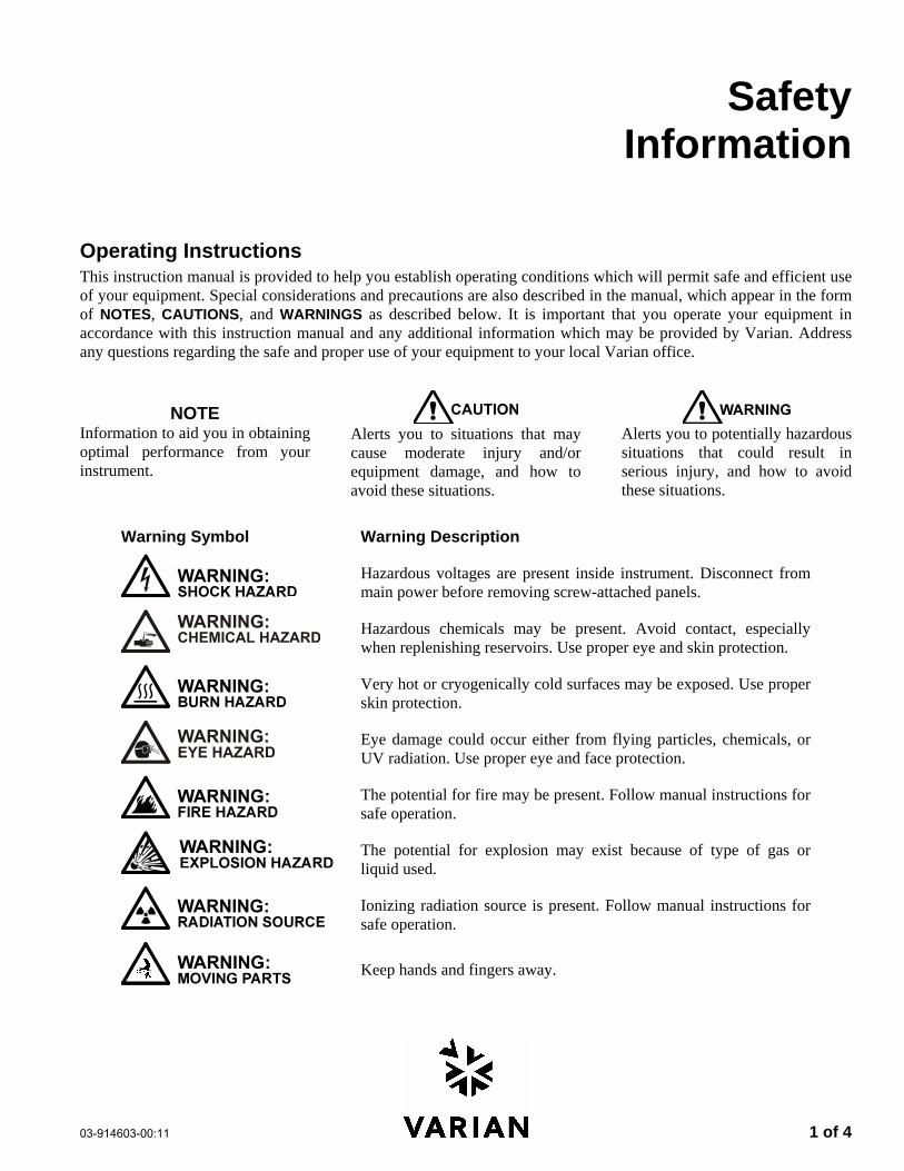
Operating Instructions This instruction manual is provided to help you establish operating conditions which will permit safe and efficient use of your equipment. Special considerations and precautions are also described in the manual, which appear in the form of NOTES, CAUTIONS, and WARNINGS as described below. It is important that you operate your equipment in accordance with this instruction manual and any additional information which may be provided by Varian. Address any questions regarding the safe and proper use of your equipment to your local Varian office.
NOTE Information to aid you in obtaining optimal performance from your instrument.
Alerts you to situations that may cause moderate injury and/or equipment damage, and how to avoid these situations.
Alerts you to potentially hazardous situations that could result in serious injury, and how to avoid these situations.
Warning Symbol Warning Description
Hazardous voltages are present inside instrument. Disconnect from main power before removing screw-attached panels.
Hazardous chemicals may be present. Avoid contact, especially when replenishing reservoirs. Use proper eye and skin protection.
Very hot or cryogenically cold surfaces may be exposed. Use proper skin protection.
Eye damage could occur either from flying particles, chemicals, or UV radiation. Use proper eye and face protection.
The potential for fire may be present. Follow manual instructions for safe operation.
The potential for explosion may exist because of type of gas or liquid used.
Ionizing radiation source is present. Follow manual instructions for safe operation.
Keep hands and fingers away.
2 of 4 03-914603-00:11
General Safety Precautions Follow these safety practices to ensure safe equipment operation.
Perform periodic leak checks on all supply lines and pneumatic plumbing. Do not allow gas lines to become kinked or punctured. Place lines away from foot traffic
and extreme heat or cold. Store organic solvents in fireproof, vented and clearly labeled cabinets so they are easily
identified as toxic and/or flammable materials. Do not accumulate waste solvents. Dispose of such materials through a regulated disposal
program and not through municipal sewage lines.
NOTICE: This instrument has been tested per applicable requirements of EMC Directive as required to carry the European Union CE Mark. As such, this equipment may be susceptible to radiation/interference levels or frequencies which are not within the tested limits.
This instrument is designed for chromatographic analysis of appropriately prepared samples. It must be operated using appropriate gases and/or solvents and within specified maximum ranges for pressure, flows, and temperatures as described in this manual. If the equipment is used in a manner not specified by the manufacturer, the protection provided by the equipment may be impaired.
It is the responsibility of the Customer to inform Varian Customer Support Representatives if the instrument has been used for the analysis of hazardous biological, radioactive, or toxic samples, prior to any instrument service being performed or when an instrument is being returned to the Service Center for repair.
Electrical Hazards Disconnect the instrument from all power sources before removing protective panels to avoid
exposure to potentially dangerous voltages. When it is necessary to use a non-original power cord plug, make sure the replacement cord adheres
to the color coding and polarity described in the manual and all local building safety codes. Replace blown fuses with fuses of the size and rating stipulated on the fuse panel or in the manual. Replace faulty or frayed power cords immediately with the same type and rating. Make sure that voltage sources and line voltage match the value for which the instrument is wired.
Compressed Gas Cylinders Store and handle compressed gases carefully and in strict adherence to safety codes. Secure cylinders to an immovable structure or wall. Store and move cylinders in an upright, vertical position. Before transport, remove regulators
and install cylinder cap. Store cylinders in a well-ventilated area away from heat, direct sunshine, freezing
temperatures, and ignition sources. Mark cylinders clearly so there is no doubt as to their contents. Use only approved regulators and connections. Use only connector tubing that is chromatographically clean (Varian Part Number 03-918326-00)
and has a pressure rating significantly greater than the highest outlet pressure from the regulator.
03-914603-00:11 3 of 4
GC Safety Practices Exhaust System No special exhaust ducting is necessary for GC detectors installed in a well-ventilated room except when the detectors are used to test hazardous chemicals. If you do install ducting:
Use only fireproof ducting. Install a blower at the duct outlet. Locate duct intakes such that their vibration or air
movement does not effect detector operation. Check periodically for proper operation of the duct. Ensure proper ventilation in lab area.
Radioactive Source Detectors
Read carefully and comply with all NOTES, CAUTIONS, and WARNINGS in the Ni63 ECD manual.
Perform the tests for removable radioactive contamination described in the Ni63 ECD manual.
Comply with leak test schedules and procedures.
Burn Hazard Heated or cryogenically cooled zones of gas chromatographs can remain hot or cold for a considerable time after instrument power is turned off. To prevent painful burns, ensure that all heated or cooled areas have returned to room temperature or wear adequate hand protection before you touch potentially hot or cold surfaces.
LC Safety Practices High Pressure Hazard
• If a line ruptures, a relief device opens, or a valve opens accidentally under pressure, potentially hazardous high liquid pressures can be generated by the pump causing a high velocity stream of volatile and/or toxic liquids.
Wear face protection when you inject samples or perform routine maintenance.
Never open a solvent line or valve under pressure. Stop the pump first and let the pressure drop to zero.
Use shatter-proof reservoirs capable of operating at 50-60 psi.
Keep the reservoir enclosure closed when the reservoir is under pressure.
Read and adhere to all NOTES, CAUTIONS, and WARNINGS in the manual.
Flash Chromatography The operator should be familiar with the physico-chemical properties of the components of the mobile phase.
Keep solvents from direct contact with the polyurethane supply tubing as certain solvents will cause weakening and leaks with possible bursting.
All components of the system should be connected to a common power supply and common ground. This ground must be a true ground rather than a floating ground.
Non-polar solvents can develop a static charge when pumped through the system. All vessels that contain mobile phase (including tubing and collection vessels) must be grounded to dissipate static electricity.
Employ static measuring and static discharge devices (e.g., air ionizers) to safeguard against the buildup of static electricity.
Ultraviolet Radiation Liquid chromatograph detectors that use an ultraviolet light source have shielding to prevent radiation exposure to personnel.
For continued protection:
Ensure that protective lamp covers of variable and fixed wavelength detectors are in place during operation.
Do not look directly into detector fluid cells or at the UV light source. When inspecting the light source or fluid cell, always use protective eye covering such as borosilicate glass or polystyrene.
The following is a Federal Communications Commission advisory: This equipment has been tested and found to comply with the limits of a Class A computing device, pursuant to part 15 of the FCC Rules. These limits are designed to provide reasonable protection against harmful interference when the equipment is operated in a commercial environment. This equipment generates, uses, and can radiate radio frequency energy and, if not installed and used in accordance with the instruction manual, may cause harmful interference to radio communications. Operation of this equipment in a residential area is likely to cause harmful interference in which case the user will be required to correct the interference at his own expense.
4 of 4 03-914603-00:11
Spare Parts Availability It is the policy of Varian to provide operational spare parts for any instrument and major accessory for a period of five (5) years after shipment of the final production run of that instrument. Spare parts will be available after this five (5) year period but on an as available basis. Operational spare parts are defined as those individual electrical or mechanical parts that are susceptible to failure during their normal operation. Examples include relays, lamps, temperature probes, detector elements, motors, etc. Sheet metal parts, structural members or assemblies and castings, printed circuit boards, and functional modules are normally capable of being rebuilt to like-new condition throughout their useful life and therefore will be supplied only on an as available basis after the final production run of the instrument.
Service Availability Varian provides a variety of services to support its customers after warranty expiration. Repair service can be provided by attractively priced service contracts or on a time and material basis. Technical support and training can be provided by qualified personnel on both a contractual or as-needed basis.
Varian, Inc. Analytical Instruments Sales Offices For Sales or Service assistance and to order Parts and Supplies, contact your local Varian office.
Argentina Buenos Aires Tel. +54.11.4.783.5306
Australia Mulgrave, Victoria Tel. +61.3.9566.1134
Austria Vösendorf bei Wien Tel. +43.1.699.9669
Benelux Bergen Op Zoom Tel. +31.164.282.800
Brazil and Latin America (S) São Paulo Tel. +55.11.820.0444
Canada Mississauga, Ontario Tel. 800.387.2216
China Beijing Tel. +86.106209.1727
Europe Middelburg, The Netherlands Tel. +31.118.671.000
France Les Ulis Cédex Tel. +33.1.6986.3838
Germany Darmstadt Tel. +49.6151.7030
India Mumbai Tel. +91.22.857.0787/88/89
Italy Torino Tel. +39.011.997.9111
Japan Tokyo Tel. +81.3.5232.1211
Korea Seoul Tel. +82.2.345.22452
Mexico and Latin America (N) Mexico City Tel. +52.5.523.9465
Russian Federation Moscow Tel. +7.095.937.4280
Spain Madrid Tel. +34.91.472.7612
Sweden Solna Tel. +46.8.445.1620
Switzerland Varian AG Tel. +41.848.803.800
Taiwan Taipei Hsien Tel. +886.2.698.9555
United Kingdom and Ireland Walton-on-Thames Tel. +44.1932.898000
Venezuela Valencia Tel. +58.41.257.608
United States Walnut Creek, California, USA Tel. +1.800.926.3000 (GC and GC/MS)
Tel. +1.800.367.4752 (LC)
www.varianinc.com
03-914603-81:11 1 of 4
Sicherheitsinformationen
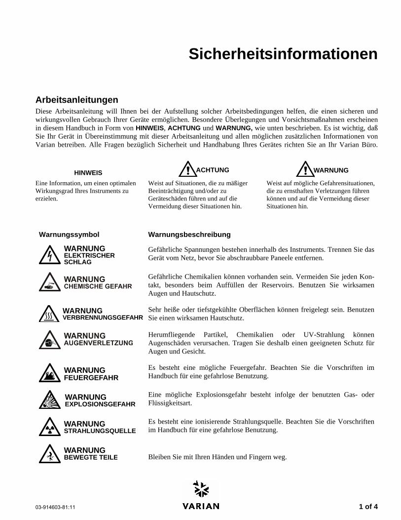
Arbeitsanleitungen Diese Arbeitsanleitung will Ihnen bei der Aufstellung solcher Arbeitsbedingungen helfen, die einen sicheren und wirkungsvollen Gebrauch Ihrer Geräte ermöglichen. Besondere Überlegungen und Vorsichtsmaßnahmen erscheinen in diesem Handbuch in Form von HINWEIS, ACHTUNG und WARNUNG, wie unten beschrieben. Es ist wichtig, daß Sie Ihr Gerät in Übereinstimmung mit dieser Arbeitsanleitung und allen möglichen zusätzlichen Informationen von Varian betreiben. Alle Fragen bezüglich Sicherheit und Handhabung Ihres Gerätes richten Sie an Ihr Varian Büro.
HINWEIS ACHTUNG WARNUNG
Eine Information, um einen optimalen Wirkungsgrad Ihres Instruments zu erzielen.
Weist auf Situationen, die zu mäßiger Beeinträchtigung und/oder zu Geräteschäden führen und auf die Vermeidung dieser Situationen hin.
Weist auf mögliche Gefahrensituationen, die zu ernsthaften Verletzungen führen können und auf die Vermeidung dieser Situationen hin.
Warnungssymbol Warnungsbeschreibung
WARNUNGELEKTRISCHERSCHLAG
Gefährliche Spannungen bestehen innerhalb des Instruments. Trennen Sie das Gerät vom Netz, bevor Sie abschraubbare Paneele entfernen.
Gefährliche Chemikalien können vorhanden sein. Vermeiden Sie jeden Kon-takt, besonders beim Auffüllen der Reservoirs. Benutzen Sie wirksamen Augen und Hautschutz.
WARNUNGVERBRENNUNGSGEFAHR
Sehr heiße oder tiefstgekühlte Oberflächen können freigelegt sein. Benutzen Sie einen wirksamen Hautschutz.
Herumfliegende Partikel, Chemikalien oder UV-Strahlung können Augenschäden verursachen. Tragen Sie deshalb einen geeigneten Schutz für Augen und Gesicht.
WARNUNGFEUERGEFAHR
Es besteht eine mögliche Feuergefahr. Beachten Sie die Vorschriften im Handbuch für eine gefahrlose Benutzung.
WARNUNGEXPLOSIONSGEFAHR
Eine mögliche Explosionsgefahr besteht infolge der benutzten Gas- oder Flüssigkeitsart.
WARNUNGSTRAHLUNGSQUELLE
Es besteht eine ionisierende Strahlungsquelle. Beachten Sie die Vorschriften im Handbuch für eine gefahrlose Benutzung.
WARNUNGBEWEGTE TEILE
Bleiben Sie mit Ihren Händen und Fingern weg.
2 of 4 03-914603-81:11
Allgemeine Sicherheitsmaßnahmen Befolgen Sie diese Sicherheitspraktiken für eine gefahrlose Gerätebenutzung.
Prüfen Sie regelmäßig alle Versorgungs und Pneumatikleitungen auf Lecks. Gasleitungen dürfen nicht geknickt oder angestochen werden. Verlegen Sie die Leitungen außer-
halb von Laufwegen und abseits von extremer Hitze oder Kälte. Lagern Sie organische Lösungsmittel in feuerfesten, belüfteten und eindeutig bezeichneten
Schränken, damit sie leicht als toxische und/oder brennbare Materialien erkannt werden. Sammeln Sie keine Lösungsmittelabfälle. Entsorgen Sie solche Materialien über ein geregeltes Ent-
sorgungsprogramm und nicht über die öffentlichen Abwasserleitungen.
HINWEIS: Dies Instrument wurde nach den zutreffenden Vorschriften der EMC Direktive getestet, die zum Führen des CE Zeichens der Europäischen Union berechtigen. Dieses Gerät kann an sich auf Strahlungs-/Störpegel oder Frequenzen außerhalb der getesteten Grenzen reagieren.
WARNUNG
Dies Instrument ist für chromatographische Analysen entsprechend präparierter Proben ge-dacht. Es muß mit geeigneten Gasen und/oder Lösungsmitteln und innerhalb der im Handbuch spezifizierten maximalen Werte für Druck, Flüsse und Temperaturen betrieben werden.
WARNUNG
Der Kunde ist vor der Durchführung irgendeines Geräteservices verpflichtet den Varian Kundendienstvertreter zu informieren, wenn das Instrument für Analysen gefährlicher biologischer, radioaktiver oder toxischer Proben benutzt worden ist.
Elektrische Gefahren Lösen Sie das Instrument von allen Stromquellen, bevor Sie Schutzpaneele entfernen, damit Sie nicht mit po-
tentiell gefährlichen Spannungen in Berührung kommen.
Wenn ein Nicht-Original Netzkabelstecker benutzt werden muß, muß das Austauschkabel die im Handbuch beschriebene Farbcodierung und Polarität beibehalten und alle örtlichen Sicherheitsvorschriften erfüllen.
Ersetzen Sie durchgebrannte Sicherungen nur mit Sicherungen der Werte, die am Sicherungspaneel oder im Handbuch angegeben sind.
Ersetzen Sie fehlerhafte oder durchgescheuerte Netzkabel sofort durch Kabel gleicher Art.
Sorgen Sie dafür, daß Spannungsquellen und die Netzspannung den gleichen Wert haben, für den das In-strument verdrahtet ist.
Gasdruckflaschen Lagern und handhaben Sie komprimierte Gase vorsichtig und in strikter Einhaltung der
Sicherheitsvorschriften.
Befestigen Sie die Gasflaschen an feststehenden Aufbauten oder an Wänden.
Lagern und transportieren Sie Gasflaschen in aufrechter Stellung. Druckregler zuvor abnehmen.
Lagern Sie Gasflaschen in gut durchlüfteten Räumen, weit genug weg von Heizungen, direktem Sonnenschein, Frosttemperaturen und Entzündungszonen.
Kennzeichnen Sie die Flaschen so eindeutig, daß kein Zweifel über deren Inhalt bestehen kann.
Benutzen Sie nur geprüfte Druckminderer und Verbindungsstücke.
Benutzen Sie nur chromatographisch reines Verbindungsrohr (Varian Part Number 03-918326-00), das wesentlich höheren Druck als den höchsten Ausgangsdruck des Druckminderers aushält.
03-914603-81:11 3 of 4
GC Sicherheitspraktiken Abgassystem Für GC Detektoren, die in einem gut durchlüfteten Raum installiert sind, ist keine spezielle Abgasführung erforderlich, außer wenn die Detektoren zum Testen gefährlicher Chemikalien benutzt werden. Wenn Sie eine Abgasführung installieren:
Benutzen Sie nur feuerfeste Führungen. Installieren Sie ein Gebläse am Ausgang. Ordnen Sie die Ansaugöffnung so an, daß ihre Er-
schütterungen oder Luftströmungen nicht die De-tektorfunktion beeinträchtigen.
Prüfen Sie regelmäßig die einwandfreie Arbeits-weise der Abgasführung.
Sorgen Sie für gute Entlüftung im Laborbereich.
Radioaktive Detektoren Lesen Sie sorgfältig und befolgen Sie alle
HINWEISE, ACHTUNGEN und WARNUNGEN im Ni63 ECD Handbuch.
Führen Sie die Tests für zu beseitigende radioak-tive Kontamination durch, die im Ni63 ECD Hand-buch beschrieben sind.
Erfüllen Sie die Zeitpläne und Verfahren zur Di-chtigkeitsprüfung.
Verbrennungsgefahr Beheizte oder tieftemperaturgekühlte Zonen des Gas-chromatographen können beträchtlich lange heiß oder kalt bleiben, nachdem das Instrument bereits abgeschal-tet ist. Zur Vermeidung schmerzhafter Verbrennungen müssen Sie darauf achten, daß alle beheizten oder gekühlten Zonen auf Raumtemperatur zurückgegangen sind oder Sie müssen ausreichenden Handschutz be-nutzen, bevor Sie möglicherweise heiße oder kalte Oberflächen berühren.
LC Sicherheitspraktiken Gefahr durch hohen Druck Wenn eine Leitung bricht, eine Entlüftungseinheit sich öffnet oder ein Ventil sich unbeabsichtigt unter Druck öffnet, kann durch die Pumpe möglicherweise ein ge-fährlich hoher Flüssigkeitsdruck entstehen, der einen Strahl flüchtiger und/oder toxischer Flüssigkeiten von hoher Stömungsgeschwindigkeit verursacht.
Tragen Sie einen Gesichtsschutz, wenn Sie Proben injizieren oder Routinewartungen durchführen.
Öffnen Sie niemals eine unter Druck stehende Lösungsmittelleitung oder ein Ventil. Halten Sie zuerst die Pumpe an und lassen Sie den Druck auf Null abfallen.
Benutzen Sie splittersichere Reservoirs, die für einen Druck von 3,4 bis 4,1 bar ausgelegt sind.
Halten Sie die Reservoirverkleidung geschlossen, wenn die Reservoirs unter Druck stehen.
Lesen Sie und befolgen Sie alle HINWEISE, ACHTUNGEN und WARNUNGEN im Handbuch.
Blitzlicht-Chromatographie Der Bediener sollte mit den physikalisch-chemischen Eigenschaften der Komponenten vertraut sein, aus denen sich die mobile Phase zusammensetzt.
Vermeiden Sie direkten Kontakt der Lösungsmittel mit den Zuführungsleitungen aus Polyurethan, da einige Lösungsmittel das Material der Leitungen schwächen und damit Undichtigkeiten oder Brüche hervorrufen können.
Alle Systemkomponenten sollten an der gleichen Netzstromquelle und einer gemeinsamen Erdung angeschlossen sein. Dabei muss es sich um eine echte, nicht um eine schwebende Erdung handeln.
Nicht-polare Lösungsmittel können sich beim Pumpen durch das System statisch aufladen. Alle Gefäße, die mobile Phase enthalten (einschließlich Leitungen und Sammelgefäße), müssen zur Ableitung elektro-statischer Aufladungen geerdet sein.
Setzen Sie Geräte zur Messung und Ableitung elektrostatischer Aufladungen (z.B. Geräte zur Luftionisierung) als Maßnahmen gegen den Aufbau statischer Elektrizität ein.
Ultraviolette Strahlung Detektoren in Liquidchromatographen, die eine ultraviolette Lichtquelle benutzen, besitzen eine Abschirmung, die das Bedienungspersonal gegen Abstrahlungen schützt. Zum ständigen Schutz:
Achten Sie darauf, daß die schützende Lampenab-deckung der Detektoren mit variablen und festen Wellenlängen während des Betriebs an ihrem Platz ist.
Schauen Sie nicht direkt in die Flüssigkeitszellen im Detektor oder in die UV Lampe. Zum In-spizieren der Lichtquelle oder der Flüssigkeitszelle benutzen Sie immer einen wirksamen Augenschutz, wie er durch Borsilikatglas oder Polystyrol gewähr-leistet wird.
4 of 4 03-914603-81:11
Verfügbarkeit von Ersatzteilen Es ist Varian’s Grundsatz, Ersatzteile für alle Instrumente und die wichtig-sten Zubehöre für einen Zeitraum von fünf (5) Jahren nach dem Fertigung-sauslauf dieser Geräteserie verfügbar zu haben. Nach diesem Zeitraum von fünf (5) Jahren können Ersatzteile auf der Basis solange vorhanden be-zogen werden. Als Ersatzteil werden hier solche elektrischen und mecha-nischen Einzelteile verstanden, die unter normalen Bedingungen ausfallen können. Beispiele sind Relais, Lampen, Temperaturfühler, Detektorele-mente, Motore usw. Metallbleche, Formteile oder Baugruppen und Gußteile, PC Boards und Funktionsmodule können normalerweise neu-wertähnlich für eine brauchbare Lebensdauer instandgesetzt werden und werden deshalb nur auf der Basis solange vorhanden nach dem Produk-tionsauslauf des Instruments geliefert werden.
Serviceverfügbarkeit Varian bietet seinen Kunden auch nach dem Auslaufen der Garantie eine Vielfalt von Serviceleistungen an. Reparaturservice kann zu attrak-tiven Preisen über eine Wartungs-vereinbarung oder nach Zeit- und Materialaufwand zur Verfügung gestellt werden. Technische Unter-stützung und Training bieten wir Ihnen durch qualifizierte Chemiker sowohl auf einer Kontraktbasis als auch nach Ihren Erfordernissen an.
Varian Analytical Instruments Verkaufsbüros Für Verkaufs oder Servicehilfe und zum Bestellen von Teilen und Zubehören setzen Sie sich bitte mit Ihrem Varian Büro in Verbindung.
Argentina Buenos Aires Tel. +54.11.4.783.5306
Australia Mulgrave, Victoria Tel. +61.3.9566.1134
Austria Vösendorf bei Wien Tel. +43.1.699.9669
Benelux Bergen Op Zoom Tel. +31.164.282.800
Brazil and Latin America (S) São Paulo Tel. +55.11.820.0444
Canada Mississauga, Ontario Tel. 800.387.2216
China Beijing Tel. +86.106209.1727
Europe Middelburg, The Netherlands Tel. +31.118.671.000
France Les Ulis Cédex Tel. +33.1.6986.3838
Germany Darmstadt Tel. +49.6151.7030
India Mumbai Tel. +91.22.857.0787/88/89
Italy Torino Tel. +39.011.997.9111
Japan Tokyo Tel. +81.3.5232.1211
Korea Seoul Tel. +82.2.345.22452
Mexico and Latin America (N) Mexico City Tel. +52.5.523.9465
Russian Federation Moscow Tel. +7.095.937.4280
Spain Madrid Tel. +34.91.472.7612
Sweden Solna Tel. +46.8.445.1620
Switzerland Varian AG Tel. +41.848.803.800
Taiwan Taipei Hsien Tel. +886.2.698.9555
United Kingdom and Ireland Walton-on-Thames Tel. +44.1932.898000
Venezuela Valencia Tel. +58.41.257.608
United States Walnut Creek, California, USA Tel. +1.800.926.3000 (GC and GC/MS)
Tel. +1.800.367.4752 (LC)
www.varianinc.com
03-914603-82:11 1 of 4
Informations et mesures de sécurité
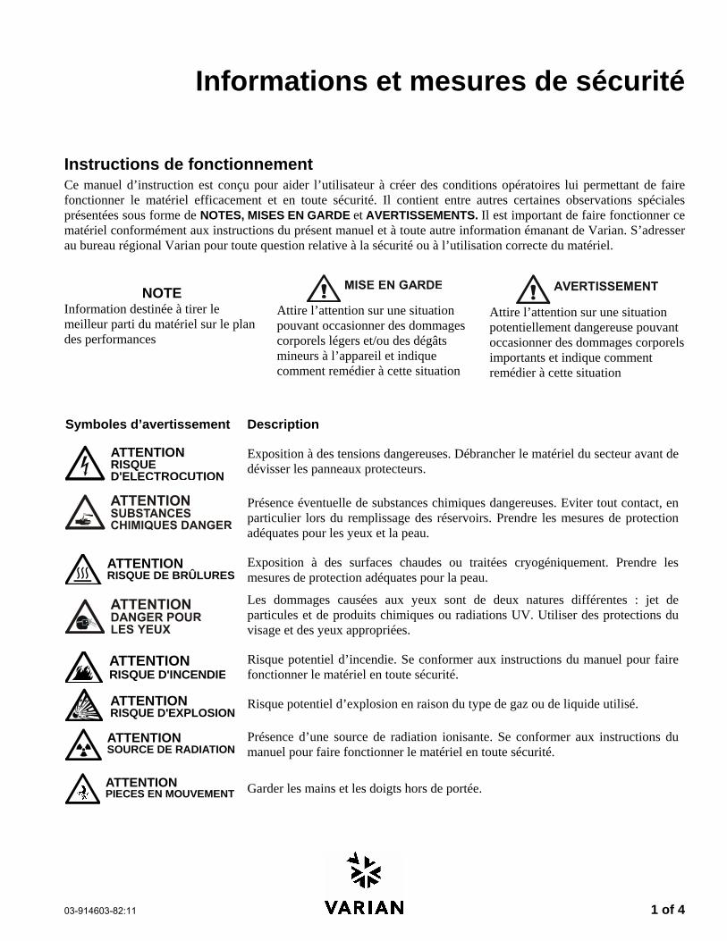
Instructions de fonctionnement Ce manuel d’instruction est conçu pour aider l’utilisateur à créer des conditions opératoires lui permettant de faire fonctionner le matériel efficacement et en toute sécurité. Il contient entre autres certaines observations spéciales présentées sous forme de NOTES, MISES EN GARDE et AVERTISSEMENTS. Il est important de faire fonctionner ce matériel conformément aux instructions du présent manuel et à toute autre information émanant de Varian. S’adresser au bureau régional Varian pour toute question relative à la sécurité ou à l’utilisation correcte du matériel.
NOTE Information destinée à tirer le meilleur parti du matériel sur le plan des performances
Attire l’attention sur une situation pouvant occasionner des dommages corporels légers et/ou des dégâts mineurs à l’appareil et indique comment remédier à cette situation
Attire l’attention sur une situation potentiellement dangereuse pouvant occasionner des dommages corporels importants et indique comment remédier à cette situation
Symboles d’avertissement Description
ATTENTIONRISQUED'ELECTROCUTION
Exposition à des tensions dangereuses. Débrancher le matériel du secteur avant de dévisser les panneaux protecteurs.
Présence éventuelle de substances chimiques dangereuses. Eviter tout contact, en particulier lors du remplissage des réservoirs. Prendre les mesures de protection adéquates pour les yeux et la peau.
ATTENTIONRISQUE DE BRÛLURES
Exposition à des surfaces chaudes ou traitées cryogéniquement. Prendre les mesures de protection adéquates pour la peau.
Les dommages causées aux yeux sont de deux natures différentes : jet de particules et de produits chimiques ou radiations UV. Utiliser des protections du visage et des yeux appropriées.
ATTENTIONRISQUE D'INCENDIE
Risque potentiel d’incendie. Se conformer aux instructions du manuel pour faire fonctionner le matériel en toute sécurité.
ATTENTIONRISQUE D'EXPLOSION
Risque potentiel d’explosion en raison du type de gaz ou de liquide utilisé.
ATTENTIONSOURCE DE RADIATION
Présence d’une source de radiation ionisante. Se conformer aux instructions du manuel pour faire fonctionner le matériel en toute sécurité.
ATTENTIONPIECES EN MOUVEMENT
Garder les mains et les doigts hors de portée.
2 of 4 03-914603-82:11
Précautions générales en matière de sécurité Les pratiques suivantes garantissent une utilisation sans risques du matériel:
Effectuer régulièrement des essais d’étanchéité de tous les conduits d’alimentation et de tous les tuyaux du système pneumatique.
Ne pas travailler avec des conduits de gaz déformés ou percés. Installer les conduits de gaz à l’écart des allées et venues et à l’abri du chaud ou du froid.
Conserver les solvants organiques dans des récipients à l’épreuve du feu, bien ventilés et portant mention de la nature de leur contenu, en particulier lorsque lesdits solvants sont toxiques et/ou inflammables.
Ne pas accumuler les solvants de rebut. Les éliminer conformément à un programme agréé d’élimination des déchets et non via les égouts municipaux.
NOTE: Ce matériel a été testé conformément aux dispositions de la directive CME afin de pouvoir porter le sigle CE de l’Union européenne. Il en résulte qu’il peut être sensible à des niveaux de radiation/d’interférence ou à des fréquences se situant hors des limites testées.
ATTENTION
Ce matériel est conçu pour effectuer des analyses chromatographiques d’échantillons préparés selon des méthodes appropriées. Il convient de le faire fonctionner avec les gaz et/ou les solvants adéquats et dans les limites des pressions, des débits et des températures maximales spécifiées dans le présent manuel.
ATTENTION
Le client est tenu d’informer le service Varian d’assistance à la clientèle que son matériel a été utilisé pour l’analyse d’échantillons biologiques dangereux, radioactifs ou toxiques avant que n’en soit effectué la maintenance.
Risques de chocs électriques Déconnecter le matériel de toute source d’alimentation avant d’en démonter les panneaux de protection, sous
peine de s’exposer à des tensions dangereuses. En cas d’utilisation d’un cordon d’alimentation n’étant pas d’origine, s’assurer que celui-ci soit conforme à la
polarité et au codage des couleurs décrits dans le manuel d’utilisation ainsi qu’à toutes les normes régionales de sécurité régissant le secteur de la construction.
Remplacer les fusibles sautés par des fusibles de même type que ceux stipulés sur le panneau des fusibles ou dans le manuel d’utilisation.
Remplacer les cordons d’alimentation défectueux ou dénudés par des cordons d’alimentation de même type. S’assurer que les sources de tension et la tension de secteur correspondent à la tension de fonctionnement du
matériel.
Bouteilles à gaz comprimé Ranger et manipuler les bouteilles à gaz comprimé avec précaution et conformément aux normes de sécurité. Fixer les bouteilles à gaz comprimé à un mur ou à une structure inamovible. Ranger et déplacer les bouteilles à gaz comprimé en position verticale. Avant de transporter les bouteilles à
gaz comprimé, retirer leur régulateur. Ranger les bouteilles dans un endroit bien ventilé et à l’abri de la chaleur, des rayons directs du soleil, du gel
ou des sources d’allumage. Marquer les bouteilles de manière à n’avoir aucun doute quant à leur contenu. N’utiliser que des connexions et régulateurs agréés. N’utiliser que des tuyaux de raccordement propres sur le plan chromatographique (Varian P/N 03-918326-00) et
pouvant supporter des pressions sensiblement plus élevées que la plus haute pression de sortie du régulateur.
03-914603-82:11 3 of 4
Mesures de sécurité en CPG Système d’échappement Les détecteurs CPG installés dans une pièce bien ventilée ne nécessitent pas de conduits spéciaux d’échappement excepté lorsqu’ils sont destinés à analyser des substances chimiques dangereuses. Lors de l’installation de tels conduits:
N’utiliser que des conduits à l’épreuve du feu
Installer un ventilateur à la sortie du conduit.
Placer les orifices d’aspiration de manière à ce que les vibrations ou les mouvements d’air n’affectent pas le fonctionnement du détecteur.
Vérifier périodiquement l’état du conduit.
S’assurer que le laboratoire est correctement ventilé.
Détecteurs à source radioactive
Se conformer au manuel d’utilisation de l’ECD Ni63, en particulier à ses NOTES, MISES EN GARDE ET AVERTISSEMENTS.
Effectuer les tests de décontamination radioactive décrits dans le manuel d’utilisation de l’ECD Ni63.
Se conformer aux procédures et au calendrier des essais d’étanchéité.
Risque de brûlures Les zones des chromatographes à gaz chauffées ou traitées cryogéniquement peuvent rester très chaudes ou très froides durant une période plus ou moins longue après la mise hors tension du matériel. Pour éviter les brûlures, s’assurer que ces zones sont revenues à température ambiante ou utiliser un dispositif adéquat de protection des mains avant de les toucher.
Mesures de sécurité en CPL Risques liés aux hautes pressions En cas de rupture d’un tuyau ou en cas d’ouverture accidentelle d’une vanne alors que le système est sous pression, la pompe peut occasionner des dommages en expulsant à grande vitesse des jets de liquides volatiles et/ou toxiques.
Mettre un masque de protection lors de l’injection des échantillons ou en effectuant les opérations de maintenance de routine.
Ne jamais déconnecter un conduit de solvant ou une vanne sous pression. Arrêter préalablement la pompe et laisser la pression descendre à zéro.
Utiliser des réservoirs incassables à 50-60 psi.
Laisser l’enceinte du réservoir fermée lorsque le réservoir est sous pression.
Se conformer aux NOTES, MISES EN GARDE ET AVERTISSEMENTS du manuel d’utilisation.
Chromatographie Flash L’utilisateur aura la connaissance des propriétés physico-chimiques des constituants de la phase mobile.
Eviter le contact direct des solvants avec les tuyaux en polyuréthane : certains solvants sont susceptibles de provoquer des faiblesses et des fuites avec risques d’explosion.
Tous les constituants du système devront être connectés à une source de courant commune et à une prise de terre commune. Cette prise de terre devra être fixe et non mobile.
Les solvants non-polaires peuvent produire de l’électricité statique lorsqu’ils passent au travers du système. Les bouteilles qui contiennent la phase mobile (incluant les tuyaux et les flacons de collecte de fractions) doivent être mises à la terre pour éliminer l’électricité statique.
Utiliser des appareils de mesure et de décharge d’électricité statique (par exemple des ionisateurs d’air) pour combattre la formation d’électricité statique.
Radiations ultraviolettes Les détecteurs CPL utilisant une source lumineuse ultraviolette comportent un écran destiné à se prémunir contre les expositions aux rayonnements.
Pour s’assurer une protection permanente:
Vérifier que le couvercle de protection de la lampe des détecteurs opérant à des longueurs d’onde variables et fixes soit bien en place durant le fonctionnement du matériel.
Ne pas regarder directement les cellules du détecteur ou la source d’UV. Se protéger systématiquement les yeux lors du contrôle de la source lumineuse ou des cellules, par exemple au moyen de verres borosilicatés ou en polystyrène.
4 of 4 03-914603-82:11
Disponibilité des pièces de rechange La politique de Varian consiste à fournir des pièces de rechange pour tous les appareils et accessoires majeurs durant une période de cinq (5) ans après livraison de leur production finale. Les pièces de rechange ne sont fournies au terme de cette période de cinq (5) ans que suivant les disponibilités. Il faut entendre par pièces de rechange les pièces individuelles électriques ou mécaniques susceptibles de défaillance au cours de leur utilisation normale. Par exemple, les relais, les lampes, les sondes thermiques, les éléments de détecteur, les moteurs, etc. Les parties en tôles, les éléments ou assemblages structurels et les pièces de fonderie, les cartes à circuits imprimés et les modules fonctionnels sont normalement susceptibles d’être remis à l’état neuf pendant toute la durée de leur vie utile et ne sont dès lors fournies, au terme de la production finale des appareils, que suivant les disponibilités.
Service d’assistance à la clientèle Varian fournit divers services destinés à aider sa clientèle après expiration de la garantie: service de réparation sur base de contrats de maintenance à prix attractifs ou sur base d’accords à durée limitée portant sur du matériel spécifique; support technique et service de formation assurés par des chimistes qualifiés sur base contractuelle ou en fonction des besoins spécifiques.
Points de vente des instruments analytiques Varian Contactez votre point de vente régional Varian pour toute question commerciale ou de service d’assistance à la clientèle ou pour passer commande de pièces et de fournitures.
Argentina Buenos Aires Tel. +54.11.4.783.5306
Australia Mulgrave, Victoria Tel. +61.3.9566.1134
Austria Vösendorf bei Wien Tel. +43.1.699.9669
Benelux Bergen Op Zoom Tel. +31.164.282.800
Brazil and Latin America (S) São Paulo Tel. +55.11.820.0444
Canada Mississauga, Ontario Tel. 800.387.2216
China Beijing Tel. +86.106209.1727
Europe Middelburg, The Netherlands Tel. +31.118.671.000
France Les Ulis Cédex Tel. +33.1.6986.3838
Germany Darmstadt Tel. +49.6151.7030
India Mumbai Tel. +91.22.857.0787/88/89
Italy Torino Tel. +39.011.997.9111
Japan Tokyo Tel. +81.3.5232.1211
Korea Seoul Tel. +82.2.345.22452
Mexico and Latin America (N) Mexico City Tel. +52.5.523.9465
Russian Federation Moscow Tel. +7.095.937.4280
Spain Madrid Tel. +34.91.472.7612
Sweden Solna Tel. +46.8.445.1620
Switzerland Varian AG Tel. +41.848.803.800
Taiwan Taipei Hsien Tel. +886.2.698.9555
United Kingdom and Ireland Walton-on-Thames Tel. +44.1932.898000
Venezuela Valencia Tel. +58.41.257.608
United States Walnut Creek, California, USA Tel. +1.800.926.3000 (GC and GC/MS)
Tel. +1.800.367.4752 (LC)
www.varianinc.com
03-914603-83:11 1 of 4
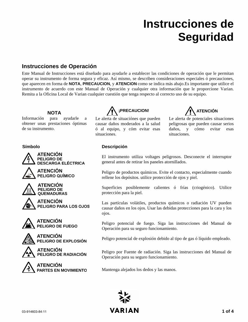
Informazioni sulla Sicurezza
Instruzioni per l’Uso Questo manuale ha lo scopo di aiutare l’operatore ad utilizzare lo strumento in modo sicuro ed efficiente. Le considerazioni e le precauzioni speciali vengono presentate in questo manuale sotto forma di avvisi di NOTA, CAUTELA e ATTENZIONE. E’ importante che lo strumento venga utilizzato rispettando le istruzioni fornite in questo manuale o che verranno fornite successivamente dalla Varian. Per ogni eventuale chiarimento sull’uso o sulla sicurezza, si prega di contattare la Varian di Leinì (TO).
NOTA Sono informazioni utili ad ottenere le prestazioni migliori da parte dello strumento.
ATTENZIONE
Allerta l’operatore su situazioni che potrebbero causare ferite leggere e danni limitati allo strumento ed il modo di evitarle.
ATTENZIONE
Allerta l’operatore su situazioni potenzialmente pericolose che possono causare danni molto seri ed il modo di evitarle.
Segnali di ATTENZIONE Descrizione del Pericolo ATTENZIONEPericolo di folgorazioni
Nello strumento sono presenti tensioni pericolose. Scollegare il cavo di alimentazione prima di togliere il pannello fissato con le viti.
Possono essere presenti composti chimici pericolosi. Evitare il contatto, specialmente quando si riempiono i contenitori. Usare protezioni opportune per la pelle e per gli occhi.
ATTENZIONEPericolo di scottature
Pericolo di esposizione a superfici molto calde o raffreddate criogenicamente. Usare protezioni opportune per la pelle.
Particelle volanti, agenti chimici o radiazioni UV possono danneggiare gli occhi. Vanno quindi utilizzate le opportune protezioni per gli occhi e per il volto.
ATTENZIONEPericolo di incendio
Pericolo potenziale di incendio. Seguire le istruzioni del manuale per lavorare con una maggiore sicurezza.
ATTENZIONEPericolo di esplosioni
C’è pericolo di esplosioni a causa del tipo di gas o liquido utilizzato.
ATTENZIONEPericolo di radiazioni
E’ presente una radiazione ionizzante. Seguire le istruzioni del manuale per lavorare con una maggiore sicurezza.
Parti in movimentoATTENZIONE
Non tenere le mani o le dita vicino.
2 of 4 03-914603-83:11
Norme di Sicurezza Per lavorare in modo sicuro sullo strumento, Vi consigliamo si adottare le seguenti procedure.
Verificare periodicamente che non ci siano perdite sulle linee e sui raccordi pneumatici. Evitare che le linee dei gas vengano piegate o forate. Le linee vanno posizionate in modo tale
da non essere calpestate e lontane da sorgenti o troppo calde o troppo fredde. I solventi organici vanno conservati in armadi speciali antiincendio, ventilati e con indicazioni
chiare sul contenuto di materiali tossici e/o infiammabili. Non accumulare i solventi utilizzati. Adottare un programma regolare di smaltimento, ma mai
nelle acque di scarico.
AVVERTENZA: Questo strumento è stato testato secondo le Direttive EMC allo scopo di poter utilizzare il Marchio CE della Comunità Europea. Questo strumento può essere suscettibile a radiazioni/interferenze o frequenze che non sono entro i limiti collaudati.
ATTENZIONE
Questo strumento è progettato per l’analisi cromatografica di campioni opportunamente preparati. Deve essere utilizzato usando gas e solventi adatti a questo scopo ed entro i limiti massimi di pressione, flusso e temperatura riportati in questo manuale. Se lo strumento non viene utilizzato secondo le modalità specificate dal costruttore, le condizioni di sicurezza previste potranno non essere sufficienti.
ATTENZIONE
E’ responsabilità del Cliente informare il Servizio Tecnico Varian, prima di qualsiasi intervento di riparazione, se lo strumento è stato utilizzato per l’analisi di campioni biologicamente pericolosi, radioattivi o tossici.
Pericoli Elettrici Prima di togliere i pannelli di protezione, scollegare lo strumento da tutte le alimentazioni
elettriche in modo da evitare l’esposizione a voltaggi potenzialmente pericolosi. Quando si rende necessario sostituire il cavo di alimentazione, assicurarsi che il nuovo cavo
rispetti sia le codifiche di colore e di polarità riportate nel manuale di istruzioni che quelle stabilite dalle norme di sicurezza del laboratorio.
Sostituire i fusibili bruciati solo con fusibili che abbiano le stesse caratteristiche; queste ultime sono riportate sul pannello dei fusibili e/o nel manuale di istruzioni.
Sostituire immediatamente i cavi di alimentazione difettosi o consumati con cavi dello stesso tipo e con le stesse caratteristiche.
Assicurarsi che il voltaggio del pannello di alimentazione corrisponda a quello dello strumento da collegare.
Bombole dei Gas Occorre prestare molta attenzione quando si spostano bombole di gas compressi. Rispettare tutte le
norme di sicurezza. Assicurare le bombole ad una parete o ad una struttura fissa. Spostare e conservare le bombole sempre in posizione verticale. Togliere i manometri prima di
spostare le bombole. Conservare le bombole in un’area ben ventilata, non infiammabile, lontana da sorgenti di calore,
non esposta a temperature troppo fredde o alla luce diretta del sole. Evidenziare in modo chiaro e che non lasci dubbi il contenuto di ogni bombola. Usare solo manometri e raccordi di qualità. Usare solo tubazioni cromatograficamente pulite (Numero di Parte Varian 03-918326-00) e calibrate
per pressioni superiori a quella massima di uscita dal manometro.
03-914603-83:11 3 of 4
Procedure di Sicurezza in GC Scarico dei Gas Per i rivelatori GC non è richiesto alcun sistema particolare di scarico dei gas, se lo strumento è installato in una stanza ben ventilata e se non viene utilizzato per l’analisi di sostanze chimiche pericolose. Se si deve installare un sistema di scarico dei gas:
Usare condutture non infiammabili Installare un aspiratore in uscita Posizionare la presa d’aria in modo che le
vibrazioni e il movimento dell’aria non disturbino il rivelatore.
Eseguire verifiche periodiche per garantire un funzionamento corretto.
Garantire una buona ventilazione nel laboratorio.
Rivelatori a Sorgente Radioattiva Leggere e rispettare tutte gli avvisi di NOTA,
CAUTELA e ATTENZIONE riportati nel manuale del rivelatore ECD al Ni63.
Eseguire tutti i test di contaminazione radioattiva rimovibile descritti nel manuale dell’ECD al Ni63.
Rispettare tutte le procedure e le scadenze di verifica per eventuali perdite.
Pericolo di Scottature Le zone calde o raffreddate criogenicamente del gascromatografo possono mantenere la loro temperatura per parecchio tempo, dopo aver spento lo strumento. Per evitare scottature, assicurarsi che le zone riscaldate o raffreddate siano a temperatura ambiente oppure indossare delle protezioni adeguate prima di toccare tali superfici.
Procedure di Sicurezza in LC Pericolo di Alte Pressioni In caso di rottura di una linea o di apertura accidentale di una valvola, quando il sistema è sotto pressione, la pompa può liberare liquidi tossici e/o volatili molto pericolosi.
E’ opportuno adottare un sistema di protezione del viso quando si inietta il campione o si esegue una manutenzione routinaria del sistema.
Non smontare mai una linea del solvente od una valvola quando il sistema è sotto pressione. Fermare prima la pompa ed aspettare che la pressione scenda a zero.
Usare dei contenitori per solventi infrangibili ed in grado di lavorare a 50-60 psi.
Quando i contenitori sono sotto pressione, usare una protezione esterna.
Leggere e rispettare tutti gli avvisi di NOTA, CAUTELA e ATTENZIONE.
Cromatografia Flash L’operatore deve conoscere le proprietà fisico-chimiche delle componenti della fase mobile.
I solventi non vanno messi in contatto diretto con il tubo di erogazione in poliuretano, dal momento che alcuni solventi possono causare indebolimento e perdite con possibili scoppi.
Tutte le componenti del sistema vanno collegate ad una fonte di alimentazione e ad una messa a terra comuni. E’ meglio che per quest’ultima venga utilizzata una spina con polo di terra.
I solventi non-polari possono sviluppare una carica statica quando vengono pompati attraverso il sistema. Tutti i recipienti che contengono la fase mobile (inclusi i tubi e i recipienti di raccolta) devono avere una messa a terra per disperdere l’elettricità statica.
Vanno utilizzati dispositivi di misurazione e scarico (ad esempio ionizzatori d’aria) per evitare l’aumento di elettricità statica.
Radiazioni Ultraviolette I rivelatori di cromatografia liquida che usano sorgenti a luce ultravioletta montano degli schermi di protezione per evitare che gli operatori siano esposti a radiazioni pericolose.
Per una protezione sicura:
Assicurarsi che i coperchi delle lampade dei rivelatori a lunghezza fissa e variabile siano sempre al loro posto, quando si lavora.
Non guardare mai direttamente dentro le celle o alla sorgente di luce UV. Quando si vuole ispezionare la lampada o le celle, usare sempre delle protezioni adatte per gli occhi, quali vetro in borosilicato e polistirolo.
4 of 4 03-914603-83:11
Disponibilità delle Parti di Ricambio E’ politica della Varian il fornire le parti di ricambio per lo strumento ed i suoi accessori per un periodo di cinque (5) anni a partire dalla data di produzione dell’ultima unità della serie. Le parti di ricambio saranno disponibili anche dopo questo periodo di cinque (5) anni ma solo in base alla disponibilità delle stesse. Per parti di ricambio si intendono i componenti elettrici e meccanici soggetti ad usura durante l’uso, in condizioni normali, dello strumento. Come esempio, citiamo i relay, le lampade, i probe di temperatura , i componenti del rivelatore, i motorini, ecc. Le parti strutturali o da fusione, le schede elettroniche ed i moduli funzionali possono essere ricostruiti e rimessi a nuovo durante tutto il loro periodo di vita e perciò sarà possibile acquistarli, dopo la produzione dell’ultima unità delle serie, solo in base alla loro disponibilità.
Servizi Tecnico La Varian, alla scadenza del periodo di garanzia, è in grado di fornire ai suoi clienti un’ampia scelta di opzioni. Le riparazioni possono essere effettuate sulla base di contratti di manutenzione particolar-mente vantaggiosi od in base ad una tariffa oraria piu’ il costo delle parti. A richiesta, si possono avere corsi per operatori sia sotto forma di contratto che a tariffe da concordare.
Uffici Vendite della Divisione Strumenti Analitici della Varian Per informazioni relative alla Vendita, al Servizio Tecnico o all’acquisto di Parti di ricambio, si prega di contattare l’ufficio Varian piu’ vicino.
Argentina Buenos Aires Tel. +54.11.4.783.5306
Australia Mulgrave, Victoria Tel. +61.3.9566.1134
Austria Vösendorf bei Wien Tel. +43.1.699.9669
Benelux Bergen Op Zoom Tel. +31.164.282.800
Brazil and Latin America (S) São Paulo Tel. +55.11.820.0444
Canada Mississauga, Ontario Tel. 800.387.2216
China Beijing Tel. +86.106209.1727
Europe Middelburg, The Netherlands Tel. +31.118.671.000
France Les Ulis Cédex Tel. +33.1.6986.3838
Germany Darmstadt Tel. +49.6151.7030
India Mumbai Tel. +91.22.857.0787/88/89
Italy Torino Tel. +39.011.997.9111
Japan Tokyo Tel. +81.3.5232.1211
Korea Seoul Tel. +82.2.345.22452
Mexico and Latin America (N)Mexico City Tel. +52.5.523.9465
Russian Federation Moscow Tel. +7.095.937.4280
Spain Madrid Tel. +34.91.472.7612
Sweden Solna Tel. +46.8.445.1620
Switzerland Varian AG Tel. +41.848.803.800
Taiwan Taipei Hsien Tel. +886.2.698.9555
United Kingdom and Ireland Walton-on-Thames Tel. +44.1932.898000
Venezuela Valencia Tel. +58.41.257.608
United States Walnut Creek, California, USA Tel. +1.800.926.3000 (GC and GC/MS)
Tel. +1.800.367.4752 (LC)
www.varianinc.com
03-914603-84:11 1 of 4
Instrucciones de Seguridad
Instrucciones de Operación Este Manual de Instrucciones está diseñado para ayudarle a establecer las condiciones de operación que le permitan operar su instrumento de forma segura y eficaz. Así mismo, se describen consideraciones especiales ó precauciones, que aparecen en forma de NOTA, PRECAUCION, y ATENCION como se indica más abajo.Es importante que utilice el instrumento de acuerdo con este Manual de Operación y cualquier otra información que le proporcione Varian. Remita a la Oficina Local de Varian cualquier cuestión que tenga respecto al correcto uso de su equipo.
NOTA Información para ayudarle a obtener unas prestaciones óptimas de su instrumento.
¡PRECAUCION!
Le alerta de situaciónes que pueden causar daños moderados a la salud ó al equipo, y cóm evitar esas situaciones.
ATENCI NÓ
Le alerta de potenciales situaciones peligrosas que pueden causar serios daños, y cómo evitar esas situaciones.
Símbolo Descripción
ATENCIÓNPELIGRO DEDESCARGA ELÉCTRICA
El instrumento utiliza voltages peligrosos. Desconecte el interruptor general antes de retirar los paneles atornillados.
Peligro de productos químicos. Evite el contacto, especialmente cuando rellene los depósitos. utilice protección de ojos y piel.
ATENCIÓNPELIGRO DEQUEMADURAS
Superficies posiblemente calientes ó frías (criogénico). Utilice protección para la piel.
Las partículas volátiles, productos químicos o radiación UV pueden causar daños en los ojos. Usar las debidas protecciones para la cara y los ojos.
ATENCIÓNPELIGRO DE FUEGO
Peligro potencial de fuego. Siga las instrucciones del Manual de Operación para su seguro funcionamiento.
ATENCIÓNPELIGRO DE EXPLOSIÓN
Peligro potencial de explosión debido al tipo de gas ó líquido empleado.
ATENCIÓNPELIGRO DE RADIACIÓN
Peligro por Fuente de radiación. Siga las instrucciones del Manual de Operación para su seguro funcionamiento.
ATENCIÓNPARTES EN MOVIMIENTO Mantenga alejados los dedos y las manos.
2 of 4 03-914603-84:11
Precauciones Generales de Seguridad Siga estas indicaciones de seguridad para una correcta operación del equipo.
Realice verificaciones periódicas de fugas en todas las líneas de suministro y tuberías.
No permita que las líneas de gas se doblen ó pinchen. Manténgalas alejadas de zonas de paso y del calor ó frío excesivo.
Guarde los disolventes orgánicos en cabinas ventiladas, a prueba de fuego, y etiquetadas para que puedan ser fácilmente identificadas como material tóxico y/ó inflamable.
No acumule disolventes inservibles. Deseche todo el material inservible a través de un programa especial de desechos y no a través del sistema convencional.
NOTA: Este instrumento ha sido testado bajo las normas de la Directiva EMC según requerimientos de la Marca CE de la Unión Europea. Por lo tanto, este equipo puede ser sensible a niveles de radiaciones / interferencias ó frecuencias que no estén incluidas dentro de los límites testados.
ATENCI NÓ
Este instrumento está diseñado para análisis cromatográfico de muestras preparadas apropiadamente. Debe ser operado usando gases y/ó disolventes apropiados y con unos niveles máximos de presión, flujos y temperaturas, según se describe en este manual.
ATENCI NÓ
El Usuario tiene la obligación de informar al Servicio Técnico de Varian cuando el instrumento vaya a ser empleado para análisis de muestras peligrosas de origen biológico, radioactivo ó tóxico, antes de comenzar a realizar cualquier análisis.
Peligros Eléctricos Desconecte el instrumento de todos las conexiones eléctricas a la red antes de retirar los
paneles para evitar la posible exposición a peligrosos voltages. Cuando sea necesario emplear una clavija eléctrica no original, asegurese de colocar los
cables de acuerdo con el código de colores y polaridades descritos en el manual y los códigos de seguridad de la red eléctrica.
Sustituya los fusibles fundidos con fusibles del tipo y tamaño estipulados en el panel de fusibles ó en el manual.
Sustituya los cables deteriorados inmediatamente con cables del mismo tipo y graduación.
Asegureses de que los valores de las líneas de electricidad se ajustan a los valores para los que el Instrumento ha sido preparado.
Botellas de Gas Comprimido Guarde y maneje las botellas de gas con cuidado y de acuerdo con las normas de seguridad. Asegure las botellas a una estructura inmovil ó a la pared. Guarde y mueva las botellas en posición vertical. Retire los reguladores antes de
transportarlas. Guarde las botellas en un área ventilada, lejos de fuentes de calor, de luz solar directa y de
temperaturas extremadamente bajas. Identifique las botellas claramente para evitar cualquier duda sobre su contenido. Utilice sólamente reguladores y conexiones aprobadas. Utilice sólo tubos de conexión cromatográficamente límpios (Varian p/n 03-918326-00) y que
tengan una graduación de presión significativamente mayor que la mayor presión del regulador.
03-914603-84:11 3 of 4
GC Prácticas de Seguridad Sistema de Extracción No se necesita un sistema de extracción para los detectores GC instalados en un laboratorio bien ventilado, excepto cuando se analicen muestras químicas peligrosas. Si instala un sistema de extracción:
Utilice conductos a prueba de fuego.
Instale un ventilador al final del sistema.
Instale entradas de aire cuya vibración no afecte al trabajo del detector.
Compruebe periódicamente el correcto funcionamiento del sistema.
Asegurese de una correcta ventilación del laboratorio.
Detectores con fuentes radioctivas
Lea con cuidado y cumpla todas las NOTAS, PRECAUCION, y ATENCION del Manual del Detector Ni63 ECD.
Realice los test de contaminación radioactiva descritos en el Manual del Detector Ni63 ECD.
Cumpla con los plazos y procedimientos de test de fugas.
Peligro de Quemaduras Las zonas de calor ó frío (criogénicas) del Cromatógrafo de Gases pueden permanecer calientes ó frías durante bastante tiempo después de apagar el instrumento. Para evitar quemaduras asegureses de que todas las áreas que se calienten ó enfríen han vuelto a la temperatura ambiente, ó protejase adecuadamente las manos, antes de tocar las superficies potencialmente calientes ó frías.
LC Prácticas de Seguridad Peligro de Alta Presión Si se rompe una línea de presión, ó se abre una válvula de seguridad accidentalmente bajo presión, la bomba puede generar líquidos a alta presión potencialmente peligrosos, produciendo un chorro a alta velocidad de líquidos volátiles y/ó tóxicos.
Lleve protección facial cuando inyecte muestras ó realice mantenimiento de rutina.
Nunca abra una línea ó una válvula bajo presión. Apague la bomba antes y deje que la presión baje a cero.
Utilice depósitos irrompibles que sean capaces de operar a 50-60 psi.
Mantenga cerrada la junta del depósito cuando se haye bajo presión.
Lea y cumpla todas las NOTA, PRECAUCION, y ATENCION del manual.
Cromatografía Flash El operador debe familiarizarse con las propiedades físico-químicas de los componentes de la fase móvil.
Alejar los disolventes del contacto directo con los tubos de poliuretano ya que ciertos disolventes pueden causar reblandecimiento de los tubos o posibles fugas con riesgo de explosión.
Todos los componentes del sistema deben estar conectados a un enchufe común con toma de tierra común. Esta toma de tierra debe ser una toma de tierra verdadera en lugar de flotante.
Los disolventes no-polares pueden originar carga estática cuando son bombeados por el sistema. Todos los recipientes que contienen fase móvil (incluyendo los tubos y los recipientes de recogida) deben estar conectados a tierra para disipar la electricidad estática.
Utilizar medidores de carga estática y los debidos dispositivos de descarga (por Ej., ionizadores de aire) para salvaguardarse contra la creación de electricidad estática.
Radiación Ultravioleta Los detectores del Cromatógrafo de Líquidos que utilizan una fuente de luz ultravioleta disponen de protección para prevenir exposiciones radioactivas al personal.
Para una correcta protección:
Asegurese de que las cubiertas de protección de la lámpara de los detectores está correctamente situada durante su funcionamiento.
No mire directamente a las celdas del detector ó a la fuente de luz UV. Cuando inspeccione la fuente de luz ó la celda, utilice siempre una protección para los ojos como gafas de borosilicato ó poliestireno.
4 of 4 03-914603-84:11
Disponibilidad de Recambios Es Política de Varian disponer de Recambios para cualquier instrumento y la mayoría de los accesorios por un periodo de cinco (5) años después del último instrumento fabricado. Los recambios durante esos cinco años estarán disponibles, pero siempre bajo el sistema “Según disponibilidad”. Los Recambios están definidos como todas aquellas partes individuales mecánicas ó eléctricas que son susceptibles de fallo durante su normal proceso de operación. Por ejemplo, relés, lámparas, sondas de temperatura, elementos del detector, motores, etc. Las planchas de metal, partes de la estructura, placas de circuitos integrados, y otros módulos funcionales son normalmente susceptibles de reparación y por lo tanto sólo estarán disponibles bajos el sistema “Según disponibilidad” después del último instrumento fabricado.
Disponibilidad de Servicio Varian ofrece una gran variedad de sistemas de Servicio para mantener el soporte a sus usuarios tras el periodo de garantía. El Soporte de Servicio se ofrece a través de atractivos Contratos de Servicio ó bajo un sistema de facturación de mano de obra y materiales. El mantenimiento y el entrenamiento se realiza por ingenieros cualificados bajo Contrato ó petición.
Oficinas de Instrumentación Analítica Varian Para cualquier consulta sobre Instrumentación Analítica, Servicio Técnico ó Recambios y Accesorios, contacte con su oficina local: Argentina Buenos Aires Tel. +54.11.4.783.5306
Australia Mulgrave, Victoria Tel. +61.3.9566.1134
Austria Vösendorf bei Wien Tel. +43.1.699.9669
Benelux Bergen Op Zoom Tel. +31.164.282.800
Brazil and Latin America (S) São Paulo Tel. +55.11.820.0444
Canada Mississauga, Ontario Tel. 800.387.2216
China Beijing Tel. +86.106209.1727
Europe Middelburg, The Netherlands Tel. +31.118.671.000
France Les Ulis Cédex Tel. +33.1.6986.3838
Germany Darmstadt Tel. +49.6151.7030
India Mumbai Tel. +91.22.857.0787/88/89
Italy Torino Tel. +39.011.997.9111
Japan Tokyo Tel. +81.3.5232.1211
Korea Seoul Tel. +82.2.345.22452
Mexico and Latin America (N)Mexico City Tel. +52.5.523.9465
Russian Federation Moscow Tel. +7.095.937.4280
Spain Madrid Tel. +34.91.472.7612
Sweden Solna Tel. +46.8.445.1620
Switzerland Varian AG Tel. +41.848.803.800
Taiwan Taipei Hsien Tel. +886.2.698.9555
United Kingdom and Ireland Walton-on-Thames Tel. +44.1932.898000
Venezuela Valencia Tel. +58.41.257.608
United States Walnut Creek, California, USA Tel. +1.800.926.3000 (GC and GC/MS)
Tel. +1.800.367.4752 (LC)
www.varianinc.com
03-914981-00:3 1
Contents
Overview of APCI......................................................................................................................3 Introduction .................................................................................................................................................................3 Basic Principles ..........................................................................................................................................................3
Positive Ion APCI .................................................................................................................................................4 Negative Ion APCI................................................................................................................................................4
Applications ................................................................................................................................................................5 Installation of APCI Chamber .....................................................................................................................................6 APCI Daily Startup and Shutdown..............................................................................................................................8
Tuning.........................................................................................................................................................................8 APCI Mobile Phase Selection.....................................................................................................................................8 Optimizing S/N for APCI .............................................................................................................................................9 Typical APCI Operating Parameters ..........................................................................................................................9 APCI Performance Evaluation..................................................................................................................................10
Operating Conditions for Testing the APCI........................................................................................................10 APCI Sensitivity Test..........................................................................................................................................10
APCI General Maintenance ....................................................................................................11 Cleaning....................................................................................................................................................................11
Cleaning the Spray Shield..................................................................................................................................11 Cleaning the Vacuum Capillary..........................................................................................................................11 Cleaning the Corona Needle..............................................................................................................................12
Replacing and Aligning the Corona Needle .............................................................................................................12 Replacing the Nebulizing Needle .............................................................................................................................13
Replacing the APCI Quartz Tube .............................................................................................................................13 Removing the Quartz Tube................................................................................................................................14 Installing the Quartz Tube..................................................................................................................................15 APCI Troubleshooting ........................................................................................................................................17
Comparison of ESI and APCI Parameters ...............................................................................................................17
APCI Spare Parts ....................................................................................................................19
03-914981-00:3 2
Atmospheric Pressure Chemical Ionization 3
Overview of APCI
Introduction For many small molecules, atmospheric pressure chemical ionization (APCI) is an excellent alternative to electrospray ionization (ESI). APCI assumes the analyte molecule has reasonable thermal stability. Thermal degradation in APCI is less likely than in GC/MS, but thermal stability is a fundamental restriction for APCI that is not shared by ESI. Optimization of APCI also requires an understanding of the relationship between the mobile phase solvents and the chemistry in the ionization process. Unlike ESI in which ions are extracted from droplets of mobile phase, APCI is a gas phase reaction between a reagent ion (typically from the mobile phase) and a neutral molecule of the analyte. This difference alters the APCI conditions for reversed phase chromatography and opens APCI to other modes of chromatography such as normal phase, and, in turn, to modified sample preparation schemes.
APCI and ESI are complementary, but significantly different in terms of setup and optimization. When the appropriate criteria for APCI have been met, chemical ionization offers advantages of increased sensitivity, enhanced selectivity, reduced interference, and robust, precise performance. For a significant number of small molecule applications, APCI may be the better solution than ESI.
Basic Principles Atmospheric Pressure Chemical Ionization (APCI) requires the following:
• The liquid flow is rapidly vaporized
• solvent molecules are ionized in the corona discharge
• Chemical Ionization ionizes sample molecules
The APCI process begins with pneumatically assisted nebulization of the LC eluent. The spray of eluent droplets are completely vaporized in a hot, turbulent flow of auxiliary gas. The stream of vaporized mobile phase and sample components flows into the API chamber and crosses the path of a corona discharge. Through a multi-step process, the corona discharge creates CI reagent ions from the large excess of mobile phase solvent molecules. A final ion-molecule reaction between these CI reagent ions and neutral molecules of analyte generates the analyte ions the mass spectrometer monitors.
03-914981-00:3 4
Positive Ion APCI Positive Ion APCI can occur as follows:
• Proton Transfer: H3O+ + M → (M+H)+ + H2O
− Also CH3OH2+, CH3CNH+, NH4
+
• Adduct Attachment: NH4+ + M → (M+ NH4)+
− Also CH3OH2+, CH3CNH+, H3O+
• Charge Exchange
Negative Ion APCI Negative Ion APCI can occur as follows:
• Proton Abstraction: OH- + M → (M - H)- + H2O
− Also CH3O-, CH2CN-
• Adduct Attachment: CH3COO- + M → (M + CH3COO)-
− Also Cl-, HCOO-
• Electron Capture
The APCI Source consists of two distinct parts, the atmospheric pressure chamber and the API capillary assembly. Vaporization, ionization and desolvation occur in the atmospheric chamber. The API capillary assembly uses a counter flow of drying gas to decluster heavily solvated ions. Using optimized gas flows and electrical potential, the API interface admits ions from the CI reaction while preventing neutrals from entering the sampling capillary.
Atmospheric Pressure Chemical Ionization 5
Metal Needle
Quartz Tube
Corona Needle
Mass Spec Inlet (to Vacuum Region and API Plug)
Sample Inlet
Heater
Cutaway View of APCI Chamber
APCI is a soft ionization process that typically produces only singly charged ions with information about the molecular ion. Adduct ions are common, but lower mass fragment ions are not. The intense pseudo-molecular ion is, however, an ideal precursor ion for MS/MS. The requirements for volatility and thermal stability limit application of APCI to molecules below ∼1500 daltons.
Applications APCI is ideally suited to non-polar and medium polarity molecules. Analytes such as polynuclear aromatic hydrocarbons (PAHs), polychlorinated biphenyls (PCBs), fatty acids, phthalates, and triglycerides are perfect candidates for APCI. The presence of one or more heteroatoms (O, N, etc.) in an analyte increases the potential for the CI reaction. As such, many drugs, pesticides, herbicides, fungicides and natural products can be analyzed with APCI. Highly charged, thermally unstable and large molecular weight analytes should be avoided. These compounds are unacceptable as analytes and should also be avoided as matrix components since the lack of volatility and degradation products may increase maintenance of the APCI vaporization assembly and chamber.
03-914981-00:3 6
Installation of APCI Chamber 1. Remove the Electrospray Ionization (ESI) chamber, if installed.
WARNING:BURN HAZARD
Source parts become hot during operation. Use caution when installing or removing the API Source.
2. Connect the gas lines to the nebulizer assembly. Nebulizing gas – top fitting. Auxiliary gas - bottom fitting.
APCI Aux Gas(Yellow)
Needle Gas (Green) (Nebulizing Gas)
N2 Connection to Needle Gas (Green)(Nebulizing Gas) ESI & APCI
N2 Connection to Drying Gas (Red) API Plug
N2 Connection to Aux Gas (Yellow)APCI Only
3. Connect the large (14-pin) round connector to the socket marked “API Housing.”
4. Connect the small (4-pin) round connector to the socket marked “APCI Plug.”
Atmospheric Pressure Chemical Ionization 7
If this is the first time an APCI chamber is being installed on this instrument, do the following.
1. Change the instrument to APCI mode, by entering APCI on the command line.
2. Before connecting the corona high voltage connector, calibrate the needle current readback.
3. Select Inst setup/others… from the Tools menu.
4. Click Zero the APCI Needle Current, and click Execute.
5. After the routine is done, plug the corona high voltage connector into the socket marked “Needle Voltage.”
6. Close and latch the chamber.
The Source must be vented to an external fume hood or an external exhaust. Failure to properly vent the ion source can result in hazardous vapors being released into the laboratory.
03-914981-00:3 8
APCI Daily Startup and Shutdown
Startup
1. Set the vaporizer and drying gas temperatures.
2. Click the spray icon to turn on the gases and heaters.
3. When the vaporizer temperature has reached to a minimum of 75% of its set value, start the LC pump.
4. After waiting a few minutes for the temperatures to stabilize, the APCI is ready to use.
Shutdown 1. Turn off the LC pump flow. Allow the pump pressure to decrease and
stabilize so flow into the interface stops.
2. Click the spray icon to turn off the gases and heaters. The heaters switch off immediately, and after a few seconds, the gases switch off. The heaters will continue to cool.
3. Check that the mobile phase is no longer flowing before opening the spray chamber.
Tuning Tune and mass axis calibrate of the 1200L mass spectrometer using the Electrospray Ionization (ESI) chamber. Refer to the Tuning section of the 1200L manual.
APCI Mobile Phase Selection Most common HPLC mobile phases are ideal for LC/MS. Normal phase solvents such as dichloromethane, hexane and toluene, while unsuitable for ESI, are well suited to APCI. APCI can handle highly aqueous mobile phase compositions; however, you should use mobile phase additives with caution. Because APCI is a gas-phase ionization method and because mobile phase constituents are present in large excess compared to the sample, severe quenching of the analyte signal can occur. Particularly troublesome are additives such as formate and acetate in negative mode APCI. APCI usually uses a higher flow rate than ESI. HPLC flow rates for APCI should be between 0.1 to 2.0 mL/min, with optimum performance realized between 0.5 and 1.0 mL/min, supporting the most common 2.1 and 4.6 mm ID HPLC columns. When operating at higher or lower flow rates, the temperature of the APCI vaporizer should be raised or lowered appropriately.
Atmospheric Pressure Chemical Ionization 9
Optimizing S/N for APCI Do Optimization for each analysis. The detector response varies for each type of analyte and is dependant on the mobile phase composition and flow rate. Typical optimization normally involves flow injection or infusion of analyte into a mobile phase flowing at the analytical flow rate and composition while adjusting N2 gas flows and temperatures to achieve maximum signal to noise. Use the syringe pump with flow rates less than 100 µL/min. However at very low flow rates there can be arcing to the shield.
The vaporizer temperature is the most significant parameter. Its optimum value is a function of:
• The sample - experimentally determined
• The mobile phase composition - more water requires a higher temperature, while a higher percentage of organic solvent requires a lower temperature
• The flow rate - higher flow rates require higher temperatures. If the temperature is very low, droplets will be observed at the outlet of the vaporizer tube. If the temperature is too high, the sample could thermally degrade.
Also important are the flow of the nebulizing and auxiliary gases, as well as the temperature and flow of the drying gas. Gas flows that are too low may cause an unstable baseline, while gas flows that are too high may reduce the size of the observed peaks.
The vaporizer can be moved back in the spray chamber to decrease the likelihood of fouling the vacuum capillary when the matrix contains a large amount of nonvolatile material (but at some expense in signal intensity). To adjust the position of the vaporizer relative to the capillary entrance, loosen the four mounting screws on top of the spray chamber and slide the vaporizer assembly forward or backward. Use the numbered scale on the right of the vaporizer assembly to assist in resetting the position. Tighten all four screws snugly when you are finished to avoid heat damaging the vaporizer. It must be firmly attached to the spray chamber for proper heat sinking.
• Reserpine: Set the capillary between +80 to +120V and monitor m/z 609.3
• 4-nitrophenol: Set the capillary between -45 to -65V and monitor m/z 138.0
• Injection: 5 μL of either the reserpine or 4-nitrophenol solution, which is 2 pg/μL (10 pg injected.)
APCI Sensitivity Test
Positive APCI Set the SIM scan mode to mass 609.3. A signal-to-noise of approximately 20:1 (RMS) or greater should be attained for 10 pg/µL reserpine (2 pg/µL, 5 µL injection by FIA) at 1 mL/min. The mobile phase is 50:50 methanol/water. Check the results in Chro using 3 point smoothing. Right-click the peak to display the signal-to-noise ratio.
Negative APCI Set the SIM scan mode to mass 138. A signal-to-noise of approximately 20:1 (RMS) or greater should be attained for 10 pg/µL nitrophenol (2 pg/µL, 5 µL injection by FIA) at 1 mL/min. The mobile phase is 50:50 methanol/water. Check the results in Chro using 3 point smoothing. Right-click the peak to display the signal-to-noise ratio.
Atmospheric Pressure Chemical Ionization 11
APCI General Maintenance
Cleaning Clean the chamber daily with methanol to decrease the accumulation of contamination. If the chamber requires more aggressive cleaning, use slurry of aluminum oxide powder to polish the inside of the housing.
Materials used for cleaning can produce hazardous vapors. Take appropriate precautions before beginning any cleaning procedure.
More extensive cleaning is required when sensitivity is lost or if excessive peak tailing occurs. Clean the drying gas spray shield, the vacuum capillary, the corona needle, and the quartz vaporizer tube.
NOTE: The quartz vaporizer tube may look dirty and the performance may not be affected. Replace it only if performance degrades.
Cleaning the Spray Shield 1. Remove the spray shield by gently rotating it off the mounting posts.
2. Wipe it with methanol or, if needed, scrubbing with an aluminum oxide powder/water slurry
3. Rinse with distilled water and then a methanol rinse.
4. Replace the spray shield by engaging one detent on the shield with one of the mounting posts and then using a gentle rotating motion to engage the other
5. Check that the capillary is visible and centered in the hole.
Cleaning the Vacuum Capillary You can rinse the outer end of the capillary without venting the system.
Using a wash bottle spray a small amounts of water or methanol into capillary. You can remove the spray shield.
If more extensive cleaning of the inside of the capillary is required, the system must be vented, the capillary removed. Place it inside a graduated cylinder in an ultrasonic bath and clean it.
03-914981-00:3 12
Cleaning the Corona Needle Wipe the corona needle with methanol. If the deposits cannot be easily removed, replace the needle as follows.
Corona Needle
Corona Needle Mount
Nebulizer Assembly
Vaporizer Tube Compression Fitting
Cutaway View of APCI Chamber
Replacing and Aligning the Corona Needle Replace the corona needle needs if it is bent, damaged, or cannot be cleaned satisfactorily.
Remove the corona needle by grasping it with your fingers and pulling it straight out of its mount. Be careful of the sharp point. Insert a new or cleaned corona needle into the mounting hole and press firmly until it is fully seated.
The alignment should not change during normal needle cleaning or replacement. The needle is properly aligned when there is 1 cm between the end of the needle and the end of the vaporizer assembly.
While firmly holding the corona needle mount, loosen the set screw in the mount with a 1.5 mm hex key and rotate the needle mount until the needle is 1 cm below the vaporizer assembly, and then retighten the set screw. Do not remove the set screw from the mount. Do not remove the needle mount from the high voltage standoff. Hold the needle mount firmly while making adjustments.
Atmospheric Pressure Chemical Ionization 13
Replacing the Nebulizing Needle If the liquid needle becomes plugged, it can be easily replaced. The needle assembly is a length of 0.004 in. ID stainless steel tubing bonded to a length of 0.005 in. ID PEEK™ tubing.
Removal Unscrew the fingertight PEEK fitting on top of the nebulizer assembly. Remove the old needle assembly from the top of the nebulizer assembly by pulling the PEEK tubing.
Installation Carefully feed the new needle assembly (03-937544-03) into the hole in the nebulizer assembly, being careful not to bend the new needle. Slide a new PEEK fingertight ferrule and nut (28-211542-00) over the end of the PEEK tubing.
While ensuring that the PEEK tube is bottomed out, gently tighten the fitting.
Nebulizer Assembly
Replacing the APCI Quartz Tube It is possible for the quartz vaporizer tube to look dirty and not affect performance. Replace the quartz tube only if performance degrades.
Keep the components as clean as possible to avoid contaminating the interface.
PEEK Tubing and Needle Assembly (03-937544-03)
03-914981-00:3 14
CAUTION
Be very careful while handling the quartz tube because it is very fragile.
WARNING:BURN HAZARD
Components become very hot and can present a burn hazard. Ensure that all parts are cool before beginning this procedure.
Removing the Quartz Tube 1. Cool the APCI vaporizer.
NOTE: To cool the vaporizer, leave the spray icon on and set the vaporizer temperature to zero. Leaving the gases on carries away residual heat.
2. Turn the gases and voltages off by clicking the spray icon (blue LED on the front of the instrument must be off.)
3. Disconnect the gas lines from the bulkhead fittings on the front of the instrument.
4. Disconnect liquid connection to injector or column (not the fitting on top of the nebulizer.)
5. Disconnect the large round (14-pin) connector from the front panel of the instrument. The socket is marked “API Housing.”
6. Disconnect the small (4-pin) round connector from the socket marked “APCI Heater.”
7. With the spray chamber still closed and latched, loosen the two screws on top of nebulizer. (The nebulizer has the heat-sink fins.)
8. Remove nebulizer assembly (03-937326-01) by lifting straight up. Set it aside carefully so nebulizer tube does not get damaged or bent.
9. Carefully remove the black O-ring (03-930109-06) from the end of the quartz tube.
The spray chamber may contain hazardous chemicals. Use appropriate protection when handling.
Atmospheric Pressure Chemical Ionization 15
10. Remove the white ceramic insulating washer (03-937323-01) and set both aside.
11. Open the spray chamber. Leave it attached to the instrument by the mounting hinge.
12. Remove corona needle (03-937344-01) from its mount by pulling straight up. Be careful of the sharp point. Set aside.
13. After checking that the vaporizer has cooled, loosen and remove the threaded compression fitting (03-937340-01) from the end of the vaporizer tube inside the spray chamber.
14. Carefully pull the quartz tube out the bottom of the vaporizer (the end in the spray chamber). Be sure to keep the tube in line with the heater as you pull it out. Do not tilt it to the side. Use a slight twisting motion if the tube binds within the heater. The ferrule will remain attached to the tube. Discard both the quartz tube and the ferrule.
Installing the Quartz Tube 1. Close and latch the spray chamber.
2. Place the white ceramic insulating washer (03-937323-01) into the cutout on the vaporizer, covering the top of the heater. Gently press on the washer to seat it in the cutout.
3. Take the new quartz tube (03-937327-01) and place the O-ring (03-930109-06) over the end. The quartz tube should be barely protruding from the O-ring for this step.
4. Carefully lower the new quartz tube into the heating coil of the vaporizer. The O-ring on the quartz tube will be resting on the insulating washer when the quartz tube is properly installed. If the quartz tube does not go in all the way, GENTLY rock the insulating washer and/or the quartz tube with gentle pressure, taking care not to break the quartz tube. DO NOT FORCE THE QUARTZ TUBE INTO THE HEATING COIL. If the quartz tube snags the heating coil and damages it, the vaporizer assembly must be replaced. Once the quartz tube is in the heating coil, gently press on the end of the tube to push it slightly below the O-ring.
Proper Depth of Quartz Tube in O-ring
Ceramic Insulating Washer (White)
Quartz Tube below surface of O-ring
O-ring
03-914981-00:3 16
5. Open the spray chamber, keeping a finger on the quartz tube through Step 7 so it doesn’t fall out.
6. Place a new polyimide ferrule (03-937339-01) over the exposed end of the quartz tube with the wider side of the ferrule toward the vaporizer assembly.
7. Replace the compression fitting and tighten finger tight. NOTE: Excessive tightening can break the quartz tube. The fitting is correctly tightened when gentle pressure on the end of the quartz tube cannot slide it within the vaporizer. Check to see that the O-ring is touching the insulating washer. The quartz tube is now fixed in place and no longer needs to be held by your finger.
8. Replace the corona needle by pressing it firmly into its mount until it bottoms.
9. Close and latch the spray chamber.
10. Replace the nebulizer assembly, lowering it straight down, using care to first pass the nebulizing tube into the quartz tube and then to engage the alignment pins (the gas lines should be on the right side). Excessive rocking of the nebulizer assembly can crack the quartz tube.
11. After checking to make sure the nebulizing assembly is straight, evenly tighten the two screws on top until snug.
12. Connect the large (14-pin) round connector to the socket marked “API Housing.”
13. Connect the small (4-pin) round connector to the socket marked “APCI Heater.”
14. Set the APCI temperature to 550 °C and click on the spray icon to turn on the gases and heaters.
15. Allow the system to bake out for 15 minutes to remove surface contamination from the new quartz tube.
16. The APCI interface is ready to use. No adjustment is necessary if the corona needle mount has not been rotated. If the corona needle needs adjustment, follow the procedure above.
Atmospheric Pressure Chemical Ionization 17
APCI Troubleshooting If no peaks are observed, but the background spectrum looks normal, the temperature may be set too low for the sample.
If smaller than expected peaks are observed or the peak shape shows extreme tailing, the temperature may be set too low.
If the background spectrum has no ions, try increasing the corona current. If operating in negative mode, be sure the nebulizing gas is air.
If condensation is observed in the spray chamber, the housing temperature may be too low for the flow conditions or there has been insufficient warm-up time.
If the baseline is noisy, it may be as a result of poor nebulization. Check the gas flows and temperatures.
If the baseline is noisy and/or elevated, the chamber may need cleaning or the mobile phase may be contaminated.
If liquid drops are seen at the end of the quartz tube it may be because the mobile phase contains a high percentage of water flowing at a high flow rate. Increase the vaporizer temperature or reduce the flow rate until the drops are no longer visible.
If intense mass peaks are observed in the background spectrum, even without liquid flow, try cleaning, then baking out the spray chamber at maximum temperature for 2 hours. If the contamination still persists then the O-rings which seal the chamber and/or the chamber windows may be contaminated and should be replaced.
If the vaporizer temperature does not increase when turned on, contact your local Varian, Inc. representative for instrument repair and service.
Comparison of ESI and APCI Parameters
PARAMETER ESI APCI Drying Gas 4L/min @ 350 °C 2L/min @ 150 °C