1972 Hasler award address Atomic Absorption Methods for the Direct Analysis of Metals and Alloys* Alan Walsh Division of Chemical Physics, Cc~wnwealth Scientific a~d Industrial Research Organization, Clayton, Victoria, Australia 3168 (Received 12 March 1973) While atomic absorption methods of spectrochemical analysis have found a wide range of application, they have been almost entirely confined to the analysis of solutions. Solid samples for anMysis have required prior solution. In recent months the situation has been trans- formed, and it has been demonstrated that some important metals and alloys can be analyzed directly by atomic absorption methods, which can be applied to the precise determination of major constituents and of trace impurities. ~NDEX ~-~EADINGS: Analysis of metals and alloys; Spectroscopy, atomic absorption; Spec- troscopy, atomic fluorescence; Atomization, cathodic sputtering; Atomization, nonflame methods. I wish to thank you most warmly for the compliment you have paid me in selecting me to be the recipient of the Maurice Hasler Award in Spectroscopy. It is in- deed a privilege to be honored by your famous Society, and the honor has an added luster in that it commemo- rates the life and work of Dr. Maurice F. Hasler. I had the good fortune to know Dr. Hasler over a period of 20 years, and I regarded him as one of the founders of modern spectrochemistry. His rare tMents were matched by a kindness and helpfulness that made each visit to his laboratory a sheer delight. It is therefore of par- ticular personal significance to me to receive an award associated with his name. Dr. Hasler's contributions were many and varied. The one which was of special interest to me was his leadership of the revolution which took emission spec- troscopy from the photographic age to the era of direct- reading multichannel instruments. These made their largest and most immediate impact on the field of metallurgical analysis, and so I thought it would be appropriate if the subject of my tIasler Award Address was one relating to this aspect of spectrochemical analysis. In particular, I would like to describe the long and tortuous path my colleagues and I have taken in an effort to develop atomic absorption and atomic fluorescence methods for the direct analysis of metals and alloys. The development of such methods involves tackling the central problem in atomic absorption spectroscopy, that of devising a satisfactory method of producing an atomic vapor of the sample for analysis. The successful * Hasler Award Address, presented at Eleventh NationM Meeting, Society for Applied Spectroscopy, Dallas, Texas, 13 September 1972. application of flame methods to a wide variety of ana- lytical problems has tended to mask the inherent limi- tations of flame atomization. Ten years ago 1 I com- mented on these limitations, pointing out that when a flame is used, some elements are only partially atomized, "thus resulting in loss in sensitivity and the possibility of chemical interference due to variations of the degree of atomization of one element with the concentration of other elements, radicals or compounds in the solu- tion .... This type of interference is present to the same extent in emission and absorption methods and is responsible for serious limitations in flame methods." This position is still with us and likely to remain. To a physicist, the flame will always be a nightmare if only because it is a veritable hot bed of chemical reactions and one in which the atoms one wishes to study are immersed in a sea of various molecular species. In addition, flame methods require the sample to be avM1- able in solution and thus cannot be adapted to the direct analysis of solid samples. Our approach to the development of a method for the direct analysis of metals and alloys was triggered off by a simple experiment which Miss B. J. Russell and I carried out in 1959. 2 We thought it would be fun to see if a hollow cathode lamp could generate resonance radiation by the mechanism illustrated in Fig. 1. The atoms sputtered from the internal surface of the cathode diffuse into the region above the cathode, where they can absorb the resonance lines emitted by the atoms within the region bounded by the cathode. This ab- sorbed radiation can then be reemitted as resonance radiation. Figs. 2 and 3 show the spectra of the radia- tion emitted at right angles to the axes of copper and chromium hollow cathode lamps and illustrate the surprisingly good isolation of the resonance lines. As a Volume 27, Number 5, 1973 APPLIED SPECTROSCOPY 335
Transcript
1972 Hasler award address
Atomic Absorption Methods for the Direct Analysis of Metals and Alloys*
Alan Walsh
Division of Chemical Physics, Cc~wnwealth Scientific a~d Industrial Research Organization, Clayton, Victoria, Australia 3168
(Received 12 March 1973)
While atomic absorption methods of spectrochemical analysis have found a wide range of application, they have been almost entirely confined to the analysis of solutions. Solid samples for anMysis have required prior solution. In recent months the situation has been trans- formed, and it has been demonstrated that some important metals and alloys can be analyzed directly by atomic absorption methods, which can be applied to the precise determination of major constituents and of trace impurities. ~NDEX ~-~EADINGS: Analysis of metals and alloys; Spectroscopy, atomic absorption; Spec- troscopy, atomic fluorescence; Atomization, cathodic sputtering; Atomization, nonflame methods.
I wish to thank you most warmly for the compliment you have paid me in selecting me to be the recipient of the Maurice Hasler Award in Spectroscopy. I t is in- deed a privilege to be honored by your famous Society, and the honor has an added luster in tha t it commemo- rates the life and work of Dr. Maurice F. Hasler. I had the good fortune to know Dr. Hasler over a period of 20 years, and I regarded him as one of the founders of modern spectrochemistry. His rare tMents were matched by a kindness and helpfulness tha t made each visit to his laboratory a sheer delight. I t is therefore of par- ticular personal significance to me to receive an award associated with his name.
Dr. Hasler 's contributions were many and varied. The one which was of special interest to me was his leadership of the revolution which took emission spec- troscopy from the photographic age to the era of direct- reading multichannel instruments. These made their largest and most immediate impact on the field of metallurgical analysis, and so I thought it would be appropriate if the subject of my tIasler Award Address was one relating to this aspect of spectrochemical analysis. In particular, I would like to describe the long and tortuous pa th my colleagues and I have taken in an effort to develop atomic absorption and atomic fluorescence methods for the direct analysis of metals and alloys.
The development of such methods involves tackling the central problem in atomic absorption spectroscopy, tha t of devising a satisfactory method of producing an atomic vapor of the sample for analysis. The successful
* Hasler Award Address, presented at Eleventh NationM Meeting, Society for Applied Spectroscopy, Dallas, Texas, 13 September 1972.
application of flame methods to a wide variety of ana- lytical problems has tended to mask the inherent limi- tations of flame atomization. Ten years ago 1 I com- mented on these limitations, pointing out tha t when a flame is used, some elements are only partially atomized, " thus resulting in loss in sensitivity and the possibility of chemical interference due to variations of the degree of atomization of one element with the concentration of other elements, radicals or compounds in the solu- tion . . . . This type of interference is present to the same extent in emission and absorption methods and is responsible for serious limitations in flame methods." This position is still with us and likely to remain. To a physicist, the flame will always be a nightmare if only because it is a veri table hot bed of chemical reactions and one in which the atoms one wishes to s tudy are immersed in a sea of various molecular species. I n addition, flame methods require the sample to be avM1- able in solution and thus cannot be adapted to the direct analysis of solid samples.
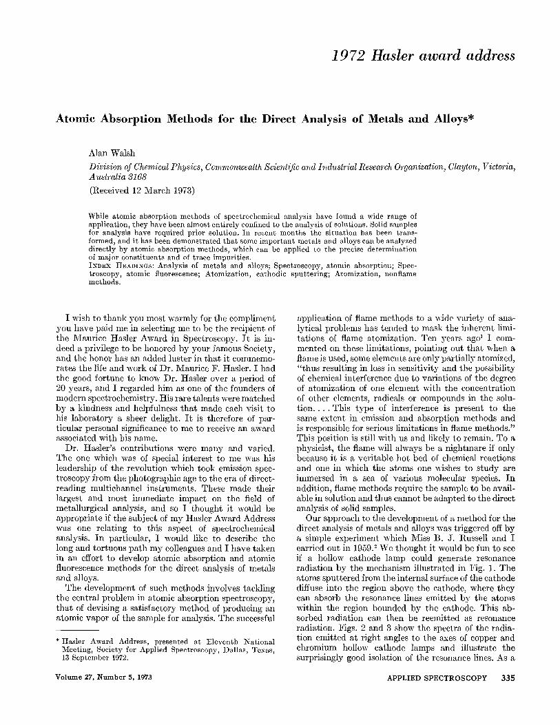
Our approach to the development of a method for the direct analysis of metals and alloys was triggered off by a simple experiment which Miss B. J. Russell and I carried out in 1959. 2 We thought it would be fun to s ee if a hollow cathode lamp could generate resonance radiation by the mechanism illustrated in Fig. 1. The a toms sputtered from the internal surface of the cathode diffuse into the region above the cathode, where they can absorb the resonance lines emitted by the atoms within the region bounded by the cathode. This ab- sorbed radiation can then be reemitted as resonance radiation. Figs. 2 and 3 show the spectra of the radia- tion emitted at right angles to the axes of copper and chromium hollow cathode lamps and illustrate the surprisingly good isolation of the resonance lines. As a
Volume 27, Number 5, 1973 APPLIED SPECTROSCOPY 3 3 5
SPECTRUM EMITTED BY CATHODE PLUS ATOMIC RESONANCE RADIATION
I.') YAP.9.U.!
ATOMIC I ".~" ~j~'~.~:.' )~/~'~ "~" ~'ZY~j RESONANCE RADIATION
+
FIG. 1. Schematic diagram illustrating the manner in which a hollow cathode tube isolates atomic resonance radiation.
(b)
..... ~[~__.JL ........
FzG. 2. Spectrum of radiation emitted along the axis of a copper hollow cathode lamp (a) and perpendicular to the axis (b). The arrows indicate resonance lines at 324.7 and 327.4 nm.
result of these experiments we suggested that the sput- tering process could be a convenient and efficient method of producing the atomic vapors which are required in the direct analysis of solids by atomic ab- sorption spectroscopy. We also suggested that the phenomenon of resonance radiation from atomic vapors produced in this manner could be used as a means of isolating resonance lines.
Before proceeding to a description of the experiments we carried out to pursue these suggestions, it may be helpful to give a brief, simplified account of some of the known characteristics of the cathodic sputtering pro- duced by glow discharges. 3 The discussion will be re- stricted to glow discharges in a rare gas since all our experiments have been concerned with this class of electrical discharge. I t is therefore assumed that there are no chemical reactions occurring at the cathode sur- face or between the sputtered particles and the filler gas.
More than 100 years ago Plticker observed that electrical discharges at low pressure result in the depo- sition of metal from cathode on the walls of the tube. Sputtering does not begin immediately but only after
336 Volume 27, l~umber 5, ].973
the discharge has run sufficiently long to "clean" the cathode surface by bombardment. The time taken to process the surface varies widely for different metals and is longest for metals such as aluminum, on the surface of which is a tenacious oxide film. The process- ing time also depends critically on the puri ty of the gas and may be several hours if molecular impurities are present. This phenomenon of cathodic sputtering has long been used as a means of producing thin metal- lic films, but the mechanism by which particles are released from the cathode is a complex one, and there is no generally accepted theory. The situation is aggra- vated by many conflicting experimental results, which are no doubt largely due to their critical dependence on the cleanliness of the cathode surface and the puri ty of the filler gas. In spite of these difficulties there is general agreement regarding the broad characteristics of the sputtering process as discussed below.
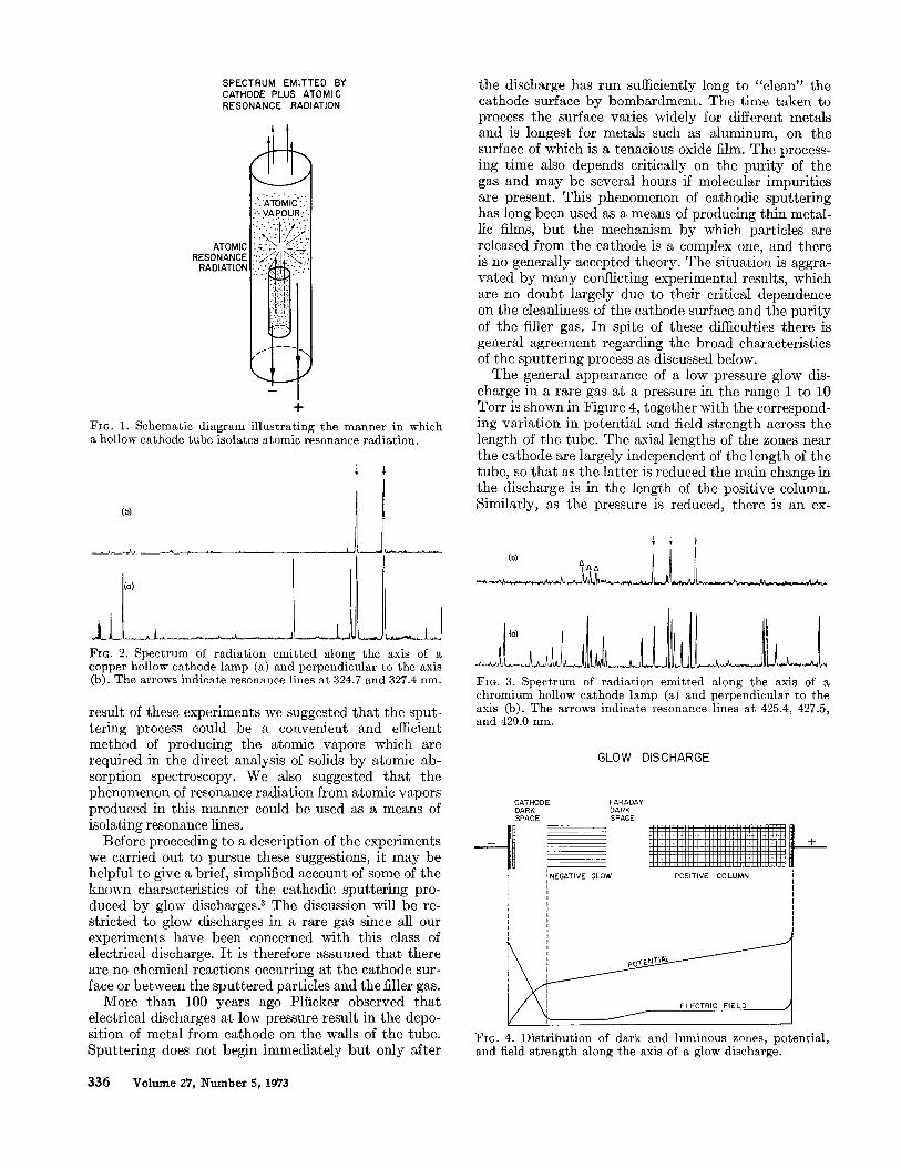
The general appearance of a low pressure glow dis- charge in a rare gas at a pressure in the range 1 to 10 Torr is shown in Figure 4, together with the correspond- ing variation in potential and field strength across the length of the tube. The axial lengths of the zones near the cathode are largely independent of the length of the tube, so that as the latter is reduced the main change in the discharge is in the length of the positive column. Similarly, as the pressure is reduced, there is an ex-
v
,ol 1 Fie. 3. Spectrum of radiation emitted along the axis of a chromium hollow cathode lamp (a) and perpendicular to the axis (b). The arrows indicate resonance lines at 425.4, 427.5, and 429.0 nm.
GLOW DISCHARGE
CATHODE FARADAY DARK DARK SPACE SPACE
il l l i i i i i i i i i i i i i i i i i i i i i i i i i i i i i i i i i I I I I I I I I I I I I i I I I I I I I I I ] I I [ I I H + J , - I / I - I ,
i i l i i l } l l ] i i i i i i E ! ! ! ! ! ! ! ! ! ! ! ! ! . . . . . ' i i i i i i i i i i [ i i i i i i i i i i i i i i i i i i i i i i l l
INEGATIVE GLOW POSITIVE COLUMN
"~ / ELECTRIC FIELD /
+
i
FiG. 4. Distribution of dark and luminous zones, potential, and field strength along the axis of a glow discharge.
pansion of the zones near the cathode at the expense of the length of the positive column. The cathode dark space, the negative glow, and the Faraday dark space can be regarded as anchored to the cathode surface, so that as the latter is rotated the negative zones also rotate while the positive column fills whatever space is available between the Faraday dark space and the anode. If the latter is positioned at the edge of the nega- tive glow, the positive column can be eliminated. I t is often desirable to operate the discharge under these conditions when absorption and/or fluorescence mea- surements are required.
Cathodic sputtering is produced by positive ions which are accelerated in the high field of the cathode fall and thus bombard the cathode surface at high velocity. This bombardment results in the sputtering of particles from the surface of the cathode. The rate of sputtering increases with the mass of the bombard- ing atom and varies markedly with the cathode mate- rial, usually increasing as the atomic heat of sublima- tion decreases. To obtain efficient sputtering, it is necessary to operate the discharge under conditions which ensure an abnormal cathode fall. This is achieved when the area of the cathode to which the discharge passes is independent of current and is indicated by the voltage across the tube increasing with current.
The particles released from the cathode are usually ground state neutral atoms which leave the cathode surface with high energy. In all the experiments to be described, the rare gas is at a pressure in the range 1 to 10 Torr, and in these cases the high energy of the sputtered atoms is rapidly dissipated by collisions with rare gas atoms. Thermal equilibrium of the sputtered atoms with the filler gas is therefore rapidly established. The sputtering and diffusion rates are such that the concentration of sputtered vapor which accumulates in the vicinity of the cathode rapidly reaches a steady state value. Our absorption and fluorescence measure- ments are usually made on the sputtered atoms which accumulate in the dark region just beyond the negative glow. My colleague, Hannaford, 4 has found that a fraction of these atoms may occupy low lying levels up to about 10(10 cm -1 or may be singly ionized. The fraction depends on the experimental conditions and varies markedly with different rare gases. He has been unable to find any definite evidence to indicate that any appreciable fraction of the sputtered material is present in any form other than single atoms.
The little evidence available regarding the composi- tion of atomic vapors sputtered from alloy cathodes is conflicting. Gillam, 5 for example, has claimed that a thin layer which is impoverished in the faster-sputtered elements rapidly forms near the surface, but once equilibrium is established this impoverished layer com- pensates for the higher sputtering rate. The composition is then expected to be the same as that of the original alloy. Several workers have supported this conclu- sion, T M but others have disputed it. 13, 14 Further experi- mental data are obviously required before the conflict can be resolved.
Ideally, the atomization process would produce an
atomic vapor of the same composition as the cathode and in which the great majority of the atoms are neutral and in the ground state. From the above discussion it is apparent that the sputtering process cannot claim to fulfil these requirements completely. On the other hand, it goes a considerable way, and possibly further than any method other than total vaporization toward pro- riding these ideal conditions. Its attractions compared with a flame are: the absence of molecular species and chemical reactions which could cause chemical inter- ferenee; a greater stability; a substantial reduction in pressure broadening and Doppler broadening; and the possibility of extending absorption and fluorescence measurements to the vacuum ultraviolet, thus permit- ting measurements on elements such as carbon and sulfur.
In order to investigate the use of cathodic sputtering as a means of atomization in atomic absorption spec- troscopy, Gatehouse and Walsh 15 used the sputtering chamber shown in Fig. 5. The sample for analysis is in the form of a cylindrical hollow cathode, 40 mm long and 12 mm internal diameter, and fits into a spring clip in the lid of the stainless steel sputtering chamber. Closing the lid seals the tube, which is then evacuated and filled with argon to a pressure of 1 Torr, and a dis- charge is passed. The discharge current may be varied according to the metal used and the sensitivity re- quired. In these experiments the current was 60 mA and was passed for 4 rain to cleaD the surface. The chamber was then evacuated and refilled with argon. After the discharge was operated for 3 min, the ab- sorption measurement was taken.
The results obtained, shown in Table I, were quite promising, but it must be remembered that the deter- ruination of silver in copper is one of the most favorable, as far as sensitivity is concerned, since the sputtering yields are high. Further encouraging results were ob- tained by Sullivan, 16 who used an improved system which permitted water-cooling of the sample. A flow through gas system speeded up the processing of the sample. A feature of these experiments was that a satisfactory calibration curve was obtained for the
NEOPRENE GASH ~ F F
FIG. g. Diagram of sputtering chamber.
APPLIED SPECTROSCOPY 337
TABLE I. Results obtained using sputtering technique developed by Gatehouse and WalshJ 5
Nominal composition No. of No. of Mean Standard
absorp- deviation of (% Ag in samples analyses tion (%) absorption
FIO. 6. Schematic diagram of an atomic absorption spectro- photometer incorporating a resonance detector.
determination of phosphorus in copper. In all these experiments, however, the precision was usually worse than =t:5 %, which is inadequate for most metallurgical analyses. Furthermore, the use of samples in the form of hollow cylinders was considered impractical for routine analysis.
Since that time other workers n-26 have used cathodic sputtering as a source of vapor in atomic absorption and atomic emission spectroscopy. In particular Grimm has developed a glow discharge lamp 27, 2s for the routine analysis of metals by ato]nic emission spectroscopy. The small number of publications on the subject, how- ever, reflects the general lack of interest in the sputter- ing method of producing atomic vapors.
But the main reason we abandoned, at least tempo- rarily, this line of work was simply because other ap- plications of the sputtering technique appeared to be more interesting. As mentioned earlier, one possibility that we became interested in was that of using the phenomenon of resonance radiation as a means of isolating resonance lines. If an atomic vapor is il- luminated by an atomic spectral lamp, then the spec- trum of the fluorescence radiation will only contain lines due to atoms which are present in the lamp and in the atomic vapor. In particular, the spectrum of the fluorescence radiation is specific to one element if, by appropriate combination of lamp and vapor, the latter only absorbs lines of that element. For example, the vapor may contain only one atomic species capable of absorbing any of the radiation emitted by the lamp. Alternatively, the lamp may emit spectral lines of only one atomic species capable of being absorbed by the vapor.
Our first applications of these properties of atomic fluorescence were concerned with the development of resonance detectors to be used as a replacement for the
338 Volume 27, Number 5, 1973
conventional monochromator in an atomic absorption spectrophotometer. This type of system is illustrated in Fig. 6. When the atomic vapor in the resonance detector is produced by cathodic sputtering, it is in- evitable that the production of atomic vapor will be accompanied by the emission of radiation, and it is essential to isolate signals due to this from those due to fluorescence radiation. This is readily achieved by modulating the radiation emitted by the atomic spectral lamp and using a synchronous detection system which responds only to signals of this frequency. Any radia- tion emitted by the dc sputtering discharge thus pro- duces no resultant signal at the output of the detection by atoms. In M1 such experiments, however, it is ira- portant to limit the amount of unmodulated radiation falling on the detector in order to avoid excessive noise. Full details of the construction and characteristics of this type of spectrophotometer have been fully dis- cussed by Sullivan and his co-workers, 294~ who have also reported on their application to various analytical problems. As far as this paper is concerned, the main significance of these investigations was to demonstrate clearly the feasibility of this type of measurement for the determination of a wide range of elements. Further- more, it was shown that the resonance radiation which can be stimulated by illuminating atomic vapors pro- duced by cathodic sputtering is of sufficient intensity to yield photoelectric signals of high signal-noise ratio. In these early experiments the main source of noise was due to the emission of radiation by the sputtering dis- charge. A great reduction in this noise was achieved by using a solar-blind photomultiplier tube, TM 3~ which has the characteristics shown in Fig. 7 and, as can be seen, l~as a negligible sensitivity for wavelengths above 3200 A. Under these conditions and using improved high intensity lamps 35 as light source, signals having
I
>
o3 Z hJ 03
I00
I0
I 15-5
II \\\ R 106
R[66
0 " I I f L i I I I T 3000A 6000/k
A --""
FIG. 7. Spectral sensitivity curve of a solar blind photo- multiplier (Hamamatsu R166).
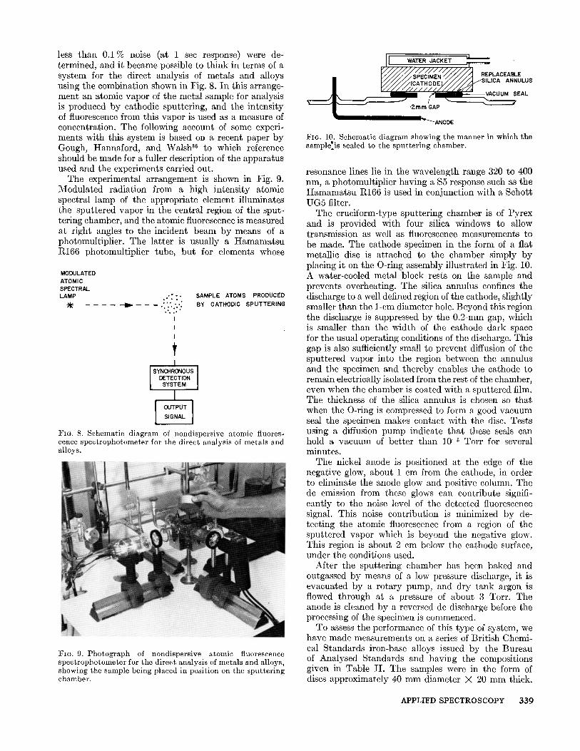
less than 0.1% noise (at 1 sec response) were de- termined, and it became possible to think in terms of a system for the direct analysis of metals and alloys using the combination shown in Fig. 8. In this arrange- ment an atomic vapor of the metal sample for analysis is produced by cathodic sputtering, and the intensity of fluorescence from this vapor is used as a measure of concentration. The following account of some experi- ments with this system is based on a recent paper by Gough, Hannaford, and Walsh 36 to which reference should be made for a fuller description of the apparatus used and the experiments carried out.
The experimental arrangement is shown in Fig. 9. Modulated radiation from a high intensity atomic spectral lamp of the appropriate element illuminates the sput tered vapor in the central region of the sput- tering chamber, and the atomic fluorescence is measured at right angles to the incident beam by means of a photomultiplier. The lat ter is usually a H a m a m a t s u R166 photomultiplier tube, but for elements whose
FIG. 8. Schematic diagram of nondispersive atomic fluores- cence spectrop}mtometer for the direct analysis of metals and alloys.
FIG. 9. Photograph of nondispersive atomic fluorescence spectrophotometer for the direct analysis of metals and alloys, showing the sample being placed in position on the sputtering chamber.
FIG. 10. Schematic diagram showing the manner in which the samplelis sealed to the sputtering chamber.
resonance lines lie in the wavelength range 320 to 400 nm, a photomultiplier having a $5 response such as the H a m a m a t s u R166 is used in conjunction with a Schott UG5 filter.
The cruciform-type sputtering chamber is of Pyrex and is provided with four silica windows to allow transmission as well as fluorescence measurements to be made. The cathode specimen in the form of a flat metallic disc is attached to the chamber simply by placing it on the O-ring assembly illustrated in Fig. i0. A water-cooled metal block rests on the sample and prevents overheating. The silica annulus confines the discharge to a well defined region of the cathode, slightly smaller than the l-cm diameter hole. Beyond this region the discharge is suppressed by the 0.2-ram gap, which is smaller than the width of the cathode dark space for the usual operating conditions of the discharge. This gap is also sufficiently small to prevent diffusion of the sputtered vapor into the region between the annulus and the specimen and thereby enables the cathode to remain electrically isolated from the rest of the chamber, even when the chamber is coated with a sputtered film. The thickness of the silica annulus is chosen so that when the O-ring is compressed to form a good vacuum seal the specimen makes contact with the disc. Tests using a diffusion pump indicate that these seals can hold a vacuum of better than 10 -5 Torr for several minutes.
The nickel anode is positioned at the edge of the negative glow, about 1 cm from the cathode, in order to eliminate the anode glow and positive column. The de emission from these glows can contribute signifi- cantly to the noise level of the detected fluorescence signal. This noise contribution is minimized by de- tecting the atomic fluorescence from a region of the sputtered vapor which is beyond the negative glow. This region is about 2 cm below the cathode surface, under the conditions used.
After the sputtering chamber has been baked and outgassed by means of a low pressure discharge, it is evacuated by a rotary pump, and dry tank argon is flowed through at a pressure of about 3 Tort. The anode is cleaned by a reversed de discharge before the processing of the specimen is commenced.
To assess the performance of this type of system, we have made measurements on a series of British Chemi- cal Standards iron-base alloys issued by the Bureau of Analysed Standards and having the compositions given in Table II. The samples were in the form of discs approximately 40 mm diameter X 20 mm thick.
APPLIED SPECTROSCOPY 3 3 9
TABLE II . Composi t ion of i ron-base alloys (Bri t ish Chemical S tandards ) . "
BCS-SS No. C (%) Si (%) S (%) P (%) Mn (%) Ni (%) Cr (%) Mo (%) V (%) Cu (%)
Composi t ions in i tal ics are those used in the p repa ra t i on of ca l ibra t ion curves.
1"7% Ni IN Fe (FRESH SURFACE)
ATOMIC FLUORESCENCE SIGNAL J
FIO. 11. Typical performance obta ined wi th the fluorescence technique for the analysis of meta ls and alloys.
These were rubbed with 500 grade silicon carbide paper to help remove oxide layers from the surface and then mounted on the silica annulus of the chamber. Fluores- cence measurements were taken using a sputtering current of 35 mA at an argon pressure of 5 Tort. Fig. 11 gives a typical fluorescence curve for this type of specimen. Linear calibration curves were obtained for the determination of Ni, Cr, Cu, Mn, and Si. The Si curve, shown in Fig. 12, does not pass through the origin. This is almost certainly due to the fact that the silicon high intensity lamp contained iron as an im- purity. I t has been estimated that using the above technique the detection limits in iron are of the order of 20 ppm for Ni, Cr, and Cu; 70 ppm for Mn; and 400 ppm for silicon. At higher concentrations the standard deviation is :t:1%. The total time recorded to change the samples and to obtain a steady reading was Wpically 3 to 4 rain.
We regard these results as extremely promising and believe they indicate that the method described will prove to be applicable to the analysis of low alloy steels. We are confident that it will also prove applicable to a wide range of other alloys, but the method in its present
I00
8O 3- I-
i - 6C _z
w
==
2c
o!5 i!o i!5 2!o PER CENT Si IN Fe
FIG. 12. Ca l ib ra t ion curve for the de te rmina t ion of silicon.
ATOMIC SPECTRAL LAMP
. : . : . . . . . . • : [
I SAMPLE ATOMS I PRODUCED BY PULSED
Y CATHODIC SPUTTERING I I I
I SYNCI-IRONOUS I DETECTION |
SYSTEM ] I
I OUTPUT I SIGNAL
FiG. 13. Schematic d iagram i l lus t ra t ing the use of the selec- t ive modula t ion technique for the direct analysis of meta ls and alloys.
form is not suitable for the analysis of aluminum alloys, which present a difficult problem owing to the oxide films which form on the surface. We propose to carry out further experiments using an argon supply which is much purer than that used in the present work. We have no accurate analysis of the argon used in our experiments, the only information provided by the supplier being: I-I20 < 12 ppm, N2 < 30 ppm, 02 < 6 ppm, I-I2 < 1 ppm, C02 etc. < 5 ppm. It is obvious
340 Volume 27, Number 5, 1973
from its emission spectrum that the argon used con- tains appreciable quantities of various molecular species. The only purification undertaken was that obtained by passage through a cold trap to remove water vapor.
A wide-ranging assessment of this technique is now under way. I t is also planned to explore the possibility of determining carbon, phosphorus, and sulfur, using a solar-blind photomultiplier which is sensitive down to 1600 A and "blind" above 2000 A.
In parallel with these fluorescence experiments an- other variant of the cathodic sputtering technique is also being investigated. The principle of the method is shown in Fig. 13. In this case the atomic spectral lamp is operated from dc while the sputtering discharge is operated from a pulsed supply which provides a pulsat- ing cloud of atoms from the sample. Thus the resonance line of a given element emitted by the atomic spectral lamp is selectively modulated to an extent proportional to the concentration of that element in the sample. This system has the advantage over the fluorescence method that it can be used in conjunction with con- ventional hollow cathode lamps although these must emit pure spectra of the element to be determined if no monochromator is used. The results obtained to date with this system have been too inconsistent to allow any meaningful assessment of its performance.
Finally, we have been encouraged to return to our original method in which the sputtering discharge is used instead of a flame in a conventional atomic ab- sorption spectrophotometer. The sample, however, is now connected to the sputtering chamber by the method illustrated in Fig. 10. The attraction of this method is that conventional equipment can easily be adapted to permit the requisite measurements. Mea- surements to date indicate that this method is less sensitive than the fluorescence method but at high concentrations the precision of both methods is ap- proximately ± 1 % .
In 14 years, therefore, we appear to have gone a full circle. During that time some of the attractive possi- bilities of the cathodic sputtering technique in atomic absorption spectroscopy have been demonstrated. We are currently carrying out investigations to determine the respective merits of atomic fluorescence, selective modulation, and conventional absorption measure- ments when used in conjunction with the sputtering technique. In the meantime I trust that this paper may encourage some adventurous analysts and en- lightened instrument manufacturers to investigate further the potentialities of the methods I have de- scribed. I t is sad indeed that at this stage we cannot have the benefit of discussing the possibilities of these new approaches to metallurgical analysis with Maurice Hasler.
ACKNOWLEDGMENTS
I am grateful to my colleagues D. S. Gough and P. Hannaford for permission to quote extensively from a paper 8~ which is still in press.
1. A. Walsh, Proc. Xth Colloquium Spectroscopicum Inter- nationale, Washington 1962, p. 127.
2. B. J. Russell and A. Walsh, Spectrochim. Acta 15, 883 (1959).
3. G. K. Wehner, Adv. Electronics Electron Phys. 7, 239 (1955).
4. P. Hannaford, private communication. 5. E. Gillam, J. Phys. Chem. Solids 11, 55 (1959). 6. W. L. Patterson and G. A. Shirn, J. Vac. Sci. Technol. 4,
343 (1967). 7. T. F. Fisher and C. E. Weber, J. Appl. Phys. 23,181 (1952). 8. R. Hanau, Phys. Rev. 75,153 (1949). 9. B. L. Flur and J. Riseman, J. Appl. Phys. 35,344 (1964).
10. M. H. Francombe and A. J. Noreika, J. Appl. Phys. 32, 97S (1961).
11. I. H. Khan and M. H. Francombe, J. Appl. Phys. 36, 1699 (1965).
12. S. D. Dahlgren, E. D. McClanahan, J. W. Johnston, and A. G. Graybeal, J. Vac. Sci. Technol. 7,398 (1970).
13. W. T. Ogar, N. T. Olson, and H. P. Smith, J. Appl. Phys. 40, 4997 (1969).
14. G. S. Anderson, J. Appl. Phys. 40, 2884 (1969). 15. B. M. Gatehouse and A. Walsh, Spectrochim. Acta 15,602
(1960). 16. J. V. Sullivan, private communication; see also Ref. 1. 17. J. A. Goleb and J. K. Brody, Anal. Chim. Acta 28, 457
(1963). 18. J. A. Goleb, Anal. Chem. 35, 1978 (1963). 19. J. A. Goleb, Anal. Chim. Acta 34,135 (1966). 20. J. A. Goleb and Yu Yokoyama, Anal. Chim. Acta 30,213
(1964). 21. J. A. Goleb, Anal. Chim. Acta 36,130 (1966). 22. N. P. Ivanov, M. N. Gusinskii, and A. D. Esikov, Zh.
Anal. Khim. 20, 1133 (1965). 23. Y. Yokoyama and S. Ikeda, Spectrochim. Acta 24B, 117
(1969). 24. C. Bordonali and M. A. Biancifiori, Proc. XV Colloquium
Spectroscopicum Internationale, Madrid, 1969, p. 269. 25. H. Massman, Spectrochim. Acta 25B, 393 (1970). 26. B. W. Gandrud and t~. K. Skogerboe, Appl. Spectrosc. 25,
243 (1971). 27. W. Grimm, Naturwiss. 54,586 (1967). 28. W. Grimm, Spectrochim. Acta 23B, 443 (1968). 29. J. V. Sullivan and A. Walsh, Spectrochim. Acta 21, 727
(1965). 30. J. V. Sullivan and A. Walsh, Spectrochim. Acta 22, 1843
(1966). 31. J. V. Sullivan, A. B. Timms, and P. A. Young, Proc.
Australian Inst. Min. Metall. No. 226, 31 (1968). 32. B. S. Rawling and J. V. Sullivan, Trans. Inst. Min. Metall.
London 75,238 (1967). 33. A. Walsh, A.S.T.M. Special Technical Publication 443,
1969. 34. P. L. Larkins, R. M. Lowe, J. V. Sullivan, and A. Walsh,
Spectrochim. Acta 24B, 187 (1969). 35. R. M. Lowe, Spectrochim. Acta 26B, 201 (1971). 36. D, S. Gough, P. Hannaford, and A. Walsh, Spectrochim.