Page 1
AECL6543
ATOMIC ENERGY » S H L'ENERGIE ATOMIQUEOF CANADA UMITED V ^ & J T DU CANADA LIMITÉE
DEAERATOR DYNAMICS
Dynamique des désaerateurs
C M . TSENG
Chalk River Nuclear Laboratories Laboratoires nucléaires de Chalk River
Chalk River, Ontario
June 1979 juin
Page 2
ATOMIC ENERGY OF CANADA LIMITED
DEAERATOR DYNAMICS
by
C.M. Tseng
Chalk River Nuclear LaboratoriesChalk River, Ontario KOJ 1JO
June 19 79
AECL-654 3
Page 3
Dynamique des désaërateurs
par
C M . Tseng
Résumé
Un modèle mathématique décrivant la dynamique d'un désaérateur dans unecentrale nucléaire CANDlf a été établi. Ce modèle peut simuler une variétéde conditions de fonctionnement thermodynamiques, â savoir:
- le fluide d'entrée se dirigeant vers le désaérateur peut être de l'eau
sous-refroidie, un mélange d'eau et de vapeur ou de la vapeur surchauf-
fée;
- dans le dësaérateur la vapeur peut être surchauffée ou saturée;
- l'eau dans le dësaérateur peut être saturée ou sous-refroidie.
Des équations linéaires concernant les petites perturbations d'une condi-
tion de référence donnée ont été développées et mises en oeuvre sur un ordi-
nateur hybride à Chalk River. Des données provenant d'un dësaérateur de la
centrale nucléaire Pickering ont été employées pour valider le modèle et les
paramètres du désaërateur de la centrale nucléaire Gentilly-1 ont servi à
illustrer sous forme graphique le comportement dynamique de la simulation.
Les fonctions de transfert du modèle ont été mesurées et comparées aux valeurs
théoriques.
L'Energie Atomique du Canada, Limitée
Laboratoires nucléaires de Chalk River
Chalk River, Ontario KOJ 1J0
Juin 1979
*CANDU - CANada Deuterium Uranium
AECL-6543
Page 4
ATOMIC ENERGY OF CANADA LIMITED
DEAERATOR DYNAMICS
by
CM. Tseng
ABSTRACT
A mathematical model, describing the dynamics of a deaera-
tor in a CANDU nuclear power plant, has been derived. The
model can simulate a variety of thermodynamic operating condi-
tions, viz., the
- input fluid to the deaerator can be subcooled water, a
saturated steam/water mixture, or superheated steam,
- steam in the deaerator can be superheated or saturated,
and
- water in the deaerator can be saturated, or subcooled.
Linearized equations, dealing with small disturbances about a
given reference condition, were developed and implemented on a
hybrid computer at the Chalk River Nuclear Laboratories.
Field data from one deaerator at the Pickering Nuclear Genera-
ting Station (NGS) were used to validate the model, and para-
meters from the Gentilly-1 NGS deaerator are used to illustrate,
in graphic form, the dynamic behaviour of the simulation.
Transfer functions of the model were measured and compared with
theoretical values.
Chalk River Nuclear LaboratoriesChalk River, Ontario KOJ 1JO
June 1979AECL-6543
Page 5
(i)
TABLE OF CONTENTS
Page
LIST OF FIGURES
LIST OF TABLES (Hi)
NOMENCLATURE dv)
1. INTRODUCTION 1
2. ASSUMPTIONS 2
3. GOVERNING EQUATIONS 5
3.1 Input Mixture 53.2 Condensation Due to Direct-Contact Mixing 6
3.3 Steam/Water Thermodynamics 6
4. DEAERATOR MODEI 8
5. REFERENCE CONDITIONS AND MODEL LINEARIZATION 12
6. MODEL IMPLEMENTATION ON THE HYBRID COMPUTER 14
7. COMPARISON OF DEAERATOR SIMULATION WITH 16PICKERING DATA
8. TEST CASE: GENTILLY-1 STEAM SUPPLY TO THE 22LA PRADE HEAVY WATER PLANT
9. FREQUENCY RESPONSE 26
10. CONCLUSIONS 29
11. REFERENCES 31
Page 6
(ii)
LIST OF FIGURES
Figure No. Title Page
1 Schematic of Deaerator 3
2 Block Diagram of Deaerator Simulation 15
3 Pickering Deaerator Pressure During 17Poison-Prevent Operation
4 Schematic of Pickering Deaerator 19Pressure Control
5 Simulation of Pickering Deaerator 21Pressure Control During the Poison-Prevent Incident
6 The Effect of Mixing Time Constant on 23Pickering Deaerator Pressure Oscil-lations During Poison-Prevent Operation
7 Gentilly-1 Deaerator Response to a 10% 24Increase in Steam Inflow, Using a 10 sMixing Time Constant
8 Gentilly-1 Deaerator Response to a 10% 25Step Decrease in Steam Inflow, Using a10 s Mixing Time Constant
9 Gentilly-1 Deaerator Response to a 27Periodic Change in Steam Inflow, Usinga 10 s Mixing Time Constant
10 Frequency Response of the Gentilly-1 28Deaerator Simulation, Assuming SubcooledWater, Saturated Steam, T = 10 sand h = h.
m f
Page 7
(Hi)
LIST OF TABLES
r.vible No. Title
1 Thermodynamic Conditions for the 8Deaerator and its Input Fluid
2 Unknowns and Governing Equations for 9Various Conditions in the Deaerator
3 Main Equations for Deaerator Model 10
4 Values of DEN for Various Conditions 14in the Deaerator
5 Controller and Valve Parameters Used 20in the Pickering Deaerator Simulation
6 Transfer Functions for the Gentilly-1 30Deaerator Simulation
Page 8
(iv)
NOMENCLATURE
functions defined in Table 3
functions defined in Tables 3, 4
thermodynamic functions defined inTable 3
h specific enthalpy J-kg"1
K normalized gain for pressure lift'Pa"1
controller
L normalized valve lift
L normalized control signal topressure-control valve
M
P
S
TI
Tm
v
x
W
W2
Greek
mass
pressure
Laplace transform variable
reset time for pressure controller
mixing time constant
specific volume
quality
mass flow
live steam inflow
kg
Pa
s-1
s
s
m'-kg-
kg-s-1
kg'S-1
e pressure difference between set- Papoint and actual value
£ damping factor of pressure controlvalve
u) natural frequency of pressure s-1
control valve
Y isentropic expansion exponent
Page 9
Symbol
Subscripts
c
ce
f
fg
g
h
i
m
ms
mw
o
P
r
s
V
w
Superscripts
(v)
NOMENCLATURE (continued)
Item
condensation
condensation due to direct-contact mixing
saturated liquid
property difference between saturated steam andsaturated water
saturated steam
constant enthalpy
i component of input flow to the deaerator
input mixture
steam component of input mixture
water component of input mixture
output to feedwater pump
constant pressure
output to relief valve
steam (not necessarily saturated)
vapourization
water (not necessarily saturated)
dt
steady-state value of the input fluid
Page 10
1. INTRODUCTION
In a CANDU-PHW* plant, the deaerator is located in
the secondary heat-transport circuit, and its main function
is to remove dissolved, corrosive gases from the feedwater
system. The deaerator consists basically of two main parts;
an upper deaerating section, containing perforated trays,
and a lower section, which is a water storage tank. Condensate
and extraction steam from various sources are piped into the
upper section where they mix and reach a common temperature.
Feed pumps circulate the water from the storage tank to the
steam generators.
The design and analysis of deaerators in power plants
is discussed in [1,2] where it is pointed out that two-stage
vacuum deaerators give considerable improvement in performance
characteristics over the single-stage designs.
Deaerator behaviour in the operation of power plants
is discussed in [3,4] where it is shown that leakage of air
into the steam space of the turbine and the discharge of
fluids from the separator into the deaerator during the startup
had an important effect on the deaerator performance.
Liao [5,6] analyzed power plant deaerators under
transient turbine loads. He presented a mathematical analysis
showing that, under a rapid load reduction of the turbine, the
differential pressure across the tray stack of the deaerator
would increase by a factor of 10 to 20 over the normal maximum
load. This might damage the deaerator. To protect it, he
recommended an on-off type deaerator bypass system [6].
Recently, Chen and Chou [7] reported on a simulation
study of deaerator control at the Pickering Nuclear Generating
Station (NGS-A). Two mathematical models, based on thermo-
dynamic equilibrium and non-equilibrium,describe the deaerator
*CANDU-PHW = CANada Deuterium Uranium reactor, Pressurized Heavy-Watercooled
Page 11
- 2 -
behaviour and are programmed on a digital computer. The
simulation predicts deaerator pressure which, in the Pickering
case, is controlled by regulating the live steam input to the
deaerator. Model predictions seem to agree with field data
taken during a poison-prevent incident.
One of the objectives of the Reactor Control Branch
at the Chalk River Nuclear Laboratories (CRNL) is to develop
a detailed, real-time simulation of a CANDU-PHW power plant,
and to implement it on a hybrid computer. This simulation
will be used to test advanced, multivariable controller
designs. A deaerator model is one subsystem of this large
simulation. The model can also provide insight into opera-
tional difficulties such as those experienced at the Pickering
NGS-A during start-up and poison-prevent operation, when
deaerator-pressure control was found to be inadequate.
The deaerator model is based on the continuity and
energy equations for steam and water, equations of state and
the constraint of a fixed overall volume. The individual
equations are linearized about steady-state operating condi-
tions, but the overall model is non-linear because different
equation sets describe various thermodynamic conditions, viz.
saturation, subcooling or superheat. No empirical relations
or constants are required to obtain solutions. The model is
shown to provide reasonable agreement with observed pressure
fluctuations in the deareator of Unit 4 of the Pickering
NGS-A.
2. ASSUMPTIONS
The deaerator is shown schematically in Figure 1.
All inlet fluids from various sources such as the main
condenser, high-pressure heaters, low-pressure heaters,
reheaters, live steam, etc. meet in the deaerating section
Page 12
DEAERATINGSECTION
STORAGETANK
i
FIG. t SCHEMATIC OF DEAERATOR
Page 13
- 4 -
where they mix and produce water which drains into the storage
tank. Steam from the storage tank is admitted to the
deaerating section through equalizers.
The following assumptions are made to obtain a
mathematical model that is reasonably simple and manageable:
(i) The enthalpy of the mixture is assumed to propagate
through the deaerating section with a time constant
proportional to the water mass on the trays.
(ii) The water mass on the trays of the deaerating
section is assumed to remain constant, and to be
small relative to the water mass in the storage
tank.
(iii) Heat transfer between phases through conduction is
neglected.
(iv) Heat transfer through the deaerator walls is also
neglected.
(v) The whole deaerator is treated as a point mass of
water and a point mass of steam at a common pressure.
(vi) Water entering the deaerating section mixes with
steam and becomes saturated before reaching the
storage tank, i.e. the water reaching the storage
tank is always saturated.
(vii) Neither steam nor water can exist in a metastable
form.
Page 14
- 5 -
3. GOVERNING EQUATIONS
3.1 Input Mixture
From the conservation of mass and energy, the theo-
retical flow and enthalpy of the mixture are
v -1 wi (1)
I w. h.V - -vn^ (2)
m
The actual mixture flow, W , that enters the storage
tank is the same as the steady-state value, W *, because we
assume that the amount of water held by the trays in the
deaerating section remains constant, i.e.
Wm = Wm* (3)
The relationship between the actual enthalpy of the
mixture, h , and the steady-state value, h *, is dependent on
the design of the trays and their operating efficiency. We
assume a first-order lag, i.e.
where the mixing time constant, T , is proportional to the
liquid mass holdup on the trays.
The quality of the mixture, x, can be determined
from
h -hcx = -S—Ê (5)
Page 15
- 6 -
The liquid and steam flow components of the inputmixture can be calculated from
Wmw
Wms " V Wmw
3.2 Condensation Due to Direct-Contact Mixing
When the input mixture to the deaerator is subcooled
water, part of the steam existing in the deaerating section
will be condensed as the water cascades down through the
stack of perforated trays. This direct-contact mixing will
ensure that the water is always saturated when it reaches
the storage tank. This contact condensation, as opposed to
the spontaneous condensation due to falling pressure, is
denoted by W and can be calculated from
w _ < h f - y WmwW (8w yWcc hfg+(hs-hg)
(8'
Note that W exists only if h < hf, i.e. the input mixture
is subcooled water, so that
Wms = °-
3.3 Steam/Water Thermodynamics
The conservation of mass and energy equations for
the point masses of steam and water are
Ms »
M = W -W -W +W +W (10)w mw v o c cc
Page 16
- 7 -
A . w V V c c c f v g
and the boundary condition is
The equations of state are
3v \ /3v(3
( Vdv \
• (
*•
vg = l^W ± iP (15)
(16)
(17)
(18)
dhf \ •- / P (19)
Page 17
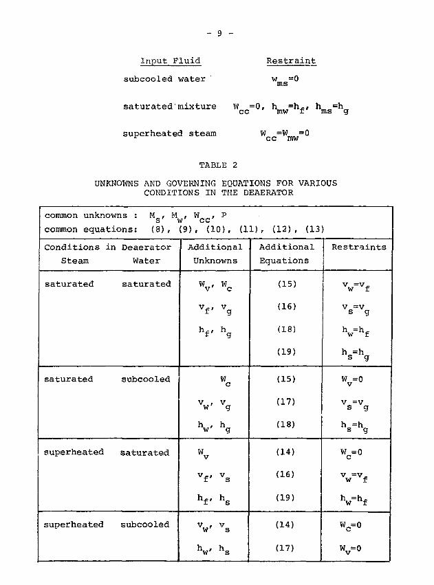
4. DEAERATOR MODEL
The possible thermodynamic conditions in the deaerator
are summarized in Table 1,
TABLE 1
THERMODYNAMIC CONDITIONS FOR THE DEAERATORAND ITS INPUT FLUID
Input Fluid
subcooled water
saturated mixture
superheated steam
Steam inDeaerator
saturated
superheated
Water inStorage Tank
saturated
subcooled
During a transient, each component may change from one state
into another; thus twelve combinations of thermodynamic
conditions are possible.
There are 14 unknowns, M , M , v_, h,, v , h , v ,S W t II CJ CJ S
h , v , h , W , W , W and P, but only 12 governing equationsS W Vr C CC V
(8) to (19), are available. Apparently, two additional
restraint conditions are required to obtain solutions. This
is provided by imposing the appropriate thermodynamic condi-
tions in the deaerator. Table 2 summarizes the proper
equations and unknowns for various conditions in the deaerator.
Based on these conditions» the final forms of sub-sets
of the governing equations can be obtained. These are given in
Table 3, where the input fluid conditions have also been applied,
i.e.
Page 18
Input Fluid
subcooled water
Restraint
w m s = 0
saturated'mixture Wcc=0 ' hmw=hf hms=hç
superheated steam W =W =0cc mw
TABLE 2
UNKNOWNS AND GOVERNING EQUATIONS FOR VARIOUSCONDITIONS IN THE DEAERATOR
common unknowns : M ,
common equations: (8),
Conditions in Deaerator
Steam
saturated
saturated
superheated
superheated
Water
saturated
subcooled
saturated
subcooled
M , W ,w ccp
(9), (10), (11)
Additional
Unknowns
Vvf,
V
VVWv
vf,
hf,
VV
Wc
vg
hg
Wc
vg
hg
vs
hs
Vs
hs
r (12), (13
Additional
Equations
(15)
(16)
(18)
(19)
(15)
(17)
(18)
(14)
(16)
(19)
(14)
(17)
)
Restraints
vw = vf
Vs=Vg
Vhf
Vhg
v°Vs=Vg
Vhg
wc=o
Vw = Vf
Vhf
wc=o
wv=o
Page 19
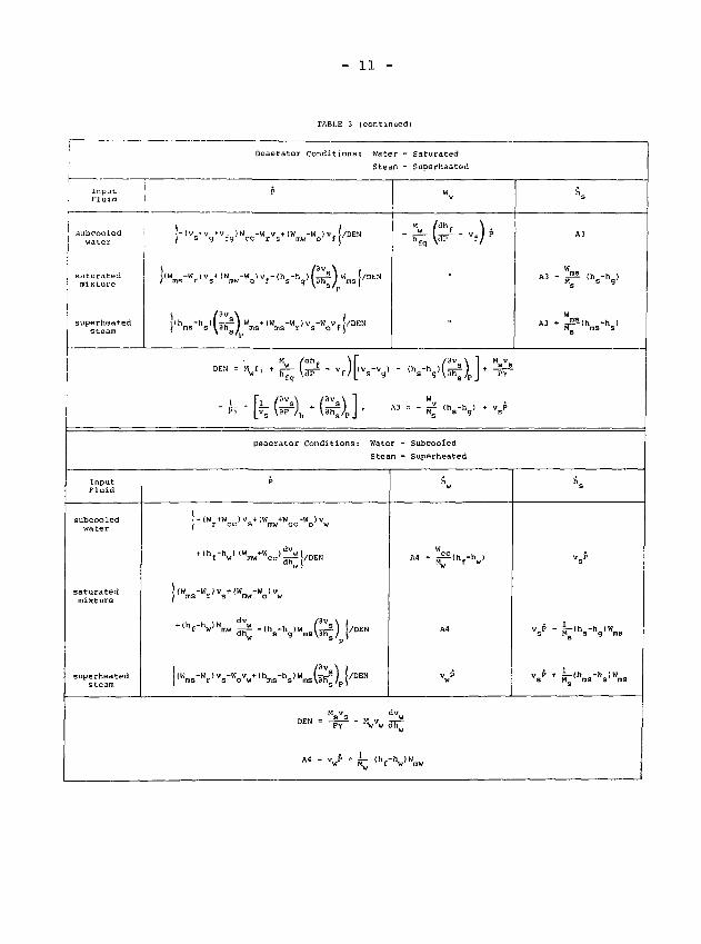
- 10 -
TABLE 3
MAIN EQUATIONS FOR DEAERATOR MODEL
InputFluid
subcooled
saturated
superheatedsteam
InputFluid
subcooledwater
saturatedmixture
superheatedsteam
Deaerator Conditions: Water -Steam -
P
WrV(Wmw-Vvf-WccvfaDEN
( Wms-W r !V I Wmw-V v fDEN
ms r g o f ^fn \ "^ 9/ '"^DEN
V, /dh, \ dv ,DEN = Msf2 + Hwf,. f, = ^[âp1 " vf/ " 3fT.
Deaerator Condi t ions : Water -
Steam -
p
1 d V " ! /DEN
Î(W -W ) v +(W -W ) v| ms r g mw o w
d v w 1+ ( V W aT^j/DEN
| ( Wms-Wr l vg-Vw
+ —j!l§ a_ | (v +v,-V ) - ( h , - h )ôû^|W >/DEN Al
DEN = HsEî +^-(^a-v g ) [<v f -vw ) - lh f-
SaturatedSaturated
Wv
Mu /dhf \ .
h f g d p
„
•••fcfr-SubcooledSaturated
wc
Al
Al
(h -h )- ms g w
M
h f g
M
h f g
w
h
\ dv
(h
A2 •
W
A 2 - - v_
fc.AVdP g,/P
/ d h \
\dP g /
^ h -hfg m s «
fiw
f -h w )
(h -h )
Page 20
- 11 -
TABLE 3 (con t inued)
InputFluid
subcooledwater
; saturatedI mixture
superheatedsteam
InputFluid
subcooledwater
saturatedmixture
superheatedsteam
i
DEN =
Dcaerator Conditions :
•} _w v + (W -W ) v vDEN
-W )vf-(h -h )1—- ) W [/\ s/p »
fg ̂ P L S
Deaerator Conditions:
P
mw-Mo ) v
W
M = v«* + k
Water
Stean
JEN
A3
Water -
Steam -
<Vhw
- Saturated
- Superheated
Wv
"w /dhf
" ̂ w 'v
»
••
Subcooled
Superheated
K
A4 + pr^V
A4
. ) •
1 + ~PY~"
w1
*.
A3
W
A3 • JSlh -h )M ins s
If p
s
Page 21
- 12 -
5. REFERENCE CONDITIONS AND MODEL LINEARIZATION
The main equations of the deac^ator model may be
implemented on a hybrid computer by using the technique
of linearizing the equations individually, around reference
conditions, and switching from one set to another as the
thermodynamic state of the steam and water changes [8,9].
A non-linear, small-signal simulation is thus obtained.
The reference condition used here is the steady-
state operating condition of the deaerator; both the water and
steam in the deaerator are saturated, and the input fluid to
the deaerator is saturated water only, i.e.
"a " K = fig ° fif = *g = *f = * = °
V = V , V = V,s g w f
h = h , h = h.es g w f
and Wms = Wr = o, h m w - hm - hf
Given the above conditions, equations (1) to (10) can be
linearized to obtain
AWm = I AW± (20)
A hm* = W- I |"(hi-hf)AWi + W± AhJ (21)
m i L J
= (Ahm* - Ahm)/Tm (22)
AWmw = AWm + K ^ (Ahf " A V (23)
Page 22
— 13 —
JLhfg
-V
AM = AW - AW + AW - AW - AW (26)s ms r v c cc
A Mw = AWmw - AWv - AWo + A Wc + AWcc (27)
The equations of Table 3 can also be linearized. It can be
seen that for all the possible cases, AP is a function of as
many as 11 independent variables. This can be reduced to
6 if the reference conditions are applied. By using DEN to
represent different values for different situations, as
given in Table 4, AP can be expressed in a single equation to
cover all cases,
(28>
The values of DEN in equation (28) depend on the conditions
in the deaerator, as summarized in Table 4. When linearized,
the other equations of Table 3 are
= V*
Ahg = vsAP (30)
MAWc = ÏT~ l ̂ " v~ / AP (31)
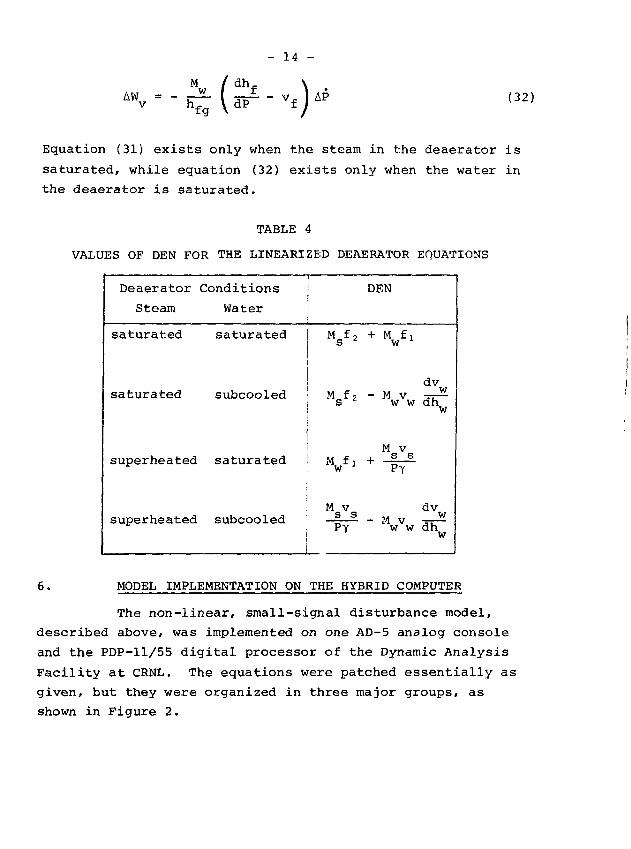
Page 23
- 14 -
M / dh, \
"r • - h £ { d T "Vf ) ̂ (32)
Equation (31) exists only when the steam in the deaerator is
saturated, while equation (32) exists only when the water in
the deaerator is saturated.
TABLE 4
VALUES OF DEN FOR THE LINEARIZED DEAERATOR EQUATIONS
Deaerator
Steam
saturated
saturated
superheated
superheated
Conditions
Water
saturated
subcooled
saturated
subcooled
Msf2
V1
M vs sPy
DEN
+ M f,w '
- M Vw w
M v... s s
PY
- M VW W
dvwdhw
dvwdhw
6. MODEL IMPLEMENTATION ON THE HYBRID COMPUTER
The non-linear, small-signal disturbance model,
described above, was implemented on one AD-5 analog console
and the PDP-11/55 digital processor of the Dynamic Analysis
Facility at CRNL. The equations were patched essentially as
given, but they were organized in three major groups, as
shown in Figure 2.
Page 24
INPUTS—>
-s.
SINPUT
MIXER
[â»,][4t0] r
[AWm«,J ^ l — 1 * * ^^—i
[AWCC]
MAIN
EQUATIONS
\ f \ f \ (
[Ah s
[ A h f
[AP]
-Ah
-Ah wl LOGICCONTFOL
OUTPUTS
FIG. 2 BLOCK DIAGRAM OF DEAERATOR SIMULATION
Page 25
- 16 -
The input mixer (Figure 2) calculates the mixture
enthalpy and flows from equations (20) to (25). The re-
sultant mixture enthalpy is compared with the saturated
value, calculated from the current deaerator pressure. The
main equations, (26) to (32), describe the steam/water thermo-
dynamics. The logic control selects the appropriate set of
equations from those given in Table 3. The variables affected
are
- AW and AW , according to Table 2
- AP (or DEN), according to Table 4
- AW , according to the thermodynamic state of thecc
input mixture.
The criteria used to determine i \e state of the steam
and water in the deaerator are as follows:
The steam is superheated if
- the pressure is rising (AP > 0), or
- the pressure is falling but the steam is super-
heated (A(hg-h ) > 0).
Similarly, the water is subcooled if
- the pressure is rising (AP > 0), or
- the pressure is falling but the water is
subcooled (A(hf-hw) > 0).
7. COMPARISON OF DEAERATOR SIMULATION WITH PICKERING
DATA
During early operation of the Pickering NGS-A, some
difficulties in controlling the deaerator pressure were en-
countered during the start-up and poison-prevent operation.
The data shown in Figure 3 were reconstructed from the
records of the poison-prevent operation of Unit 4 in
Page 26
400
TO
o.
CO
a.
ceUJ
LU
• ACTUAL READINGSLINE THROUGH READINGS
ASSUMED VALUES
2028 30
22 24 26
MINUTES SINCE TURBINE TftIP
FIG. 3 PICKERING DEAERATOR PRESSURE DURING POISON PREVENT OPERATION [71
-4
I
Page 27
- 18 -
1974 April [7]. Only the magnitude of pressure oscillations is
significant; the reconstructed frequency shown could be lower
than the actual values because of the coarse readings during
this rapidly changing transient.
To obtain a meaningful comparison, the actual Pickering
operating conditions, plus the deaerator pressure control
scheme, i.e. the PI controller algorithm and the valves with
an assumed second-order characteristic, were incorporated into
the simulation. Figure 4 shows the block diagram of the whole
Pickering deaerator pressure-control loop. It is assumed that
the mass flow of live steam is proportional to the lift of
the pressure control valve.
The PI controller algorithm was described by
: (33)
The second-order characteristic of the control valve
was expressed as
LL = — (34)
CO 9
N a,/
The numerical values of the controller and valve
parameters are given in Table 5.
Page 28
set
rPI
CONTROLLER
Lo PRESSURECONTROLVALVES
AW2 DEAERATORMODEL
AP
FIG. 4 SCHEMATIC OF PICKERING DEAERATOR PRESSURE CONTROL
Page 29
- 20 -
Linearized forms of equations (33) and (34), used for
describing small signal disturbances, are given below.
ALD = K
AL = AL
(35)
(36)
TABLE 5
CONTROLLER AND VALVE PARAMETERS USED IN THEPICKERING DEAERATOR SIMULATION
Symbol
K
TI
eWN
-
Description
normalized gain
reset time
damping factor
natural frequency
valve stroking time
5.
12
0.
0.
20
Value
80xl0~6
8
9044
Units
lift/Pa
s
-
S"1
s
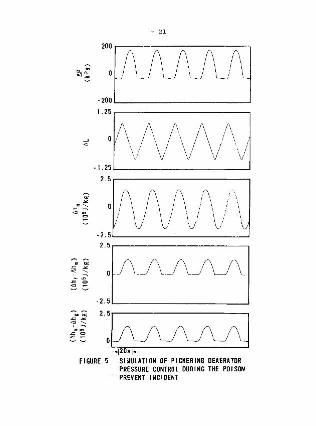
Figure 5 shows the results of the simulation, using
a mixing time constant* of 10 s and all coefficients calcu-
lated at reference (steady-state) conditions, with a
deaerator pressure of 206.8 kPa. The results indicate that
the deaerator pressure (uppermost trace in Figure 5) oscillates
over the range from (172-32) kPa to (172+170) kPa, which
agrees with the field data shown in Figure 3. The period of
36 s falls between the simulation results of Chou and Chen
(20 s) [7], and the reconstructed field data (̂ 60 s). The
results also show that the pressure in the deaerator lags the
valve lift by % 90°.
*The trays in the deaerating section hold 5.66 m3 of water, which takes•v» 10 s to fill under poison-prevent operating conditions.
Page 30
- 21
a.
og onj= -se«3 \
«9 CO
-2.5
H20s(-FIGURE 5 SIMULATION OF PICKERING DEAERATOR
PRESSURE CONTROL DURING THE POISONPREVENT INCIDENT
Page 31
- 22 -
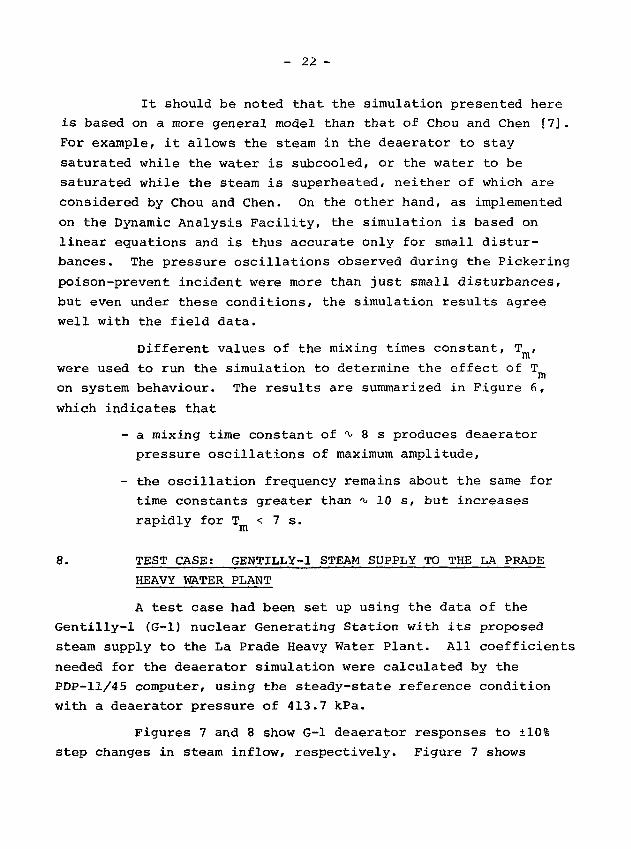
It should be noted that the simulation presented here
is based on a more general model than that of Chou and Chen [7].
For example, it allows the steam in the deaerator to stay
saturated while the water is subcooled, or the water to be
saturated while the steam is superheated, neither of which are
considered by Chou and Chen. On the other hand, as implemented
on the Dynamic Analysis Facility, the simulation is based on
linear equations and is thus accurate only for small distur-
bances. The pressure oscillations observed during the Pickering
poison-prevent incident were more than just small disturbances,
but even under these conditions, the simulation results agree
well with the field data.
Different values of the mixing times constant, T ,
were used to run the simulation to determine the effect of T
on system behaviour. The results are summarized in Figure 6,
which indicates that
- a mixing time constant of ^ 8 s produces deaerator
pressure oscillations of maximum amplitude,
- the oscillation frequency remains about the same for
time constants greater than ^ 10 s, but increases
rapidly for T < 7 s.r m
8. TEST CASE: GENTILLY-1 STEAM SUPPLY TO THE LA PRADE
HEAVY WATER PLANT
A test case had been set up using the data of the
Gentilly-1 (G-l) nuclear Generating Station with its proposed
steam supply to the La Prade Heavy Water Plant. All coefficients
needed for the deaerator simulation were calculated by the
PDP-11/45 computer, using the steady-state reference condition
with a deaerator pressure of 413.7 kPa.
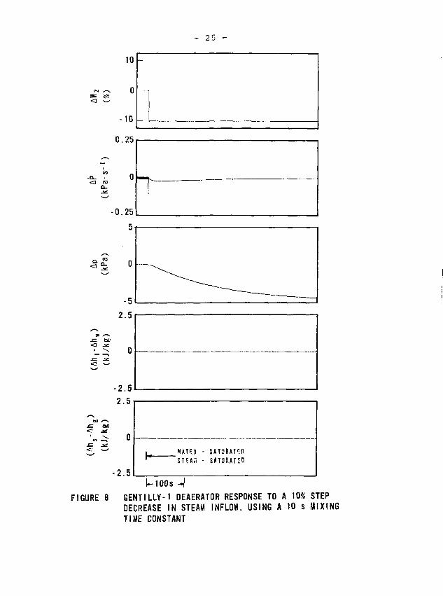
Figures 7 and 8 show G-l deaerator responses to ±10%
step changes in steam inflow, respectively. Figure 7 shows
Page 32
COQ_
400
FREQUENCY
AMPLITUDE
5 10
MIXING TIME CONSTANT (s)
20
0.08
0.06
0.04
0.02
0.0
>-o
FIG. 6 THE EFFECT OF MIXING TIME CONSTANT ON PICKERING DEAERAT0R PRESSUREOSCILLATIONS DURING POISON-PREVENT OPERATION
Page 33
10
0
<a ro
FIGURE 7
2.5
WATER - SU3C00LED
STEM - SUPERHEATED
{-100 s -IGENTILLY-1 DEAERATOR RESPONSE TO A IGINCREASE IN STEAM INFLOW, USING A 10MIXING TIME CONSTANT
Page 34
10
0
-10
0.25
<n
-0.25
5
CO' O-
-5
2.5
-2 .5
2.5
•„ - o
- 2 . 5
WATEÎ1 - SATURATEDTFAw - SOTURATED
I—100s - IFIGURE 8 GENTILLY-1 DEAERATOR RESPONSE TO A 10% STEP
DECREASE IN STEAM INFLOW, USING A 10 s MIXINGTIME CONSTANT
Page 35
- 26 -
that the step increase in AW2 instantly puts the water and
steam into the subcooled and superheated states, respectively.
A short time constant (3.3 s) dominates the response of AP,
(Ahf-Ah ) and (Ah -Ah ). The slow decrease of (Ahf-Ah ),
after the initial sharp rise, indicates that the water in the
deaerator gradually approaches a new saturated state, corres-
ponding to the higher pressure, by the process of displacement
of the existing water in the deaerator by the input flows.
Figure 8 shows that the water and steam in the
deaerator remain saturated when a -10% step in AW2 is applied.
A long time constant (183 s) prevails in the response of AP and
AP.
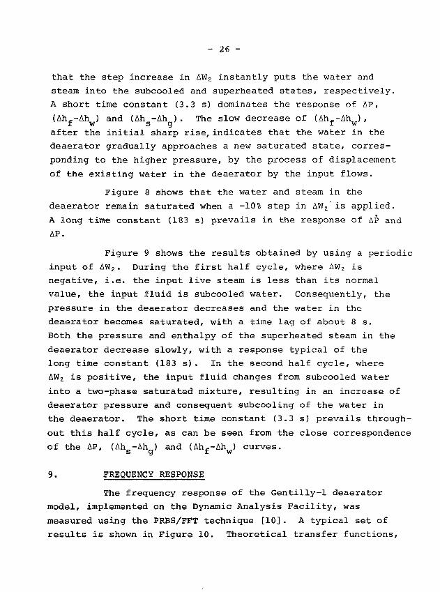
Figure 9 shows the results obtained by using a periodic
input of AW2. During the first half cycle, where AW2 is
negative, i.e. the input live steam is less than its normal
value, the input fluid is subcooled water. Consequently, the
pressure in the deaerator decreases and the water in the
deaerator becomes saturated, with a time lag of about 8 s.
Both the pressure and enthalpy of the superheated steam in the
deaerator decrease slowly, with a response typical of the
long time constant (183 s). In the second half cycle, where
AW2 is positive, the input fluid changes from subcooled water
into a two-phase saturated mixture, resulting in an increase of
deaerator pressure and consequent subcooling of the water in
the deaerator. The short time constant (3.3 s) prevails through-
out this half cycle, as can be seen from the close correspondence
of the AP, (Ah -Ah ) and (Ah--Ah ) curves.S CX 11 W
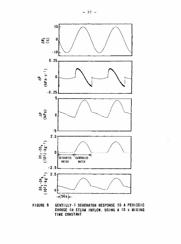
9. FREQUENCY RESPONSE
The frequency response of the Gentilly-1 deaerator
model, implemented on the Dynamic Analysis Facility, was
measured using the PRBS/FFT technique [10]. A typical set of
results is shown in Figure 10. Theoretical transfer functions,
Page 36
- 27 -
<3 O
FIGURE 9 GENTILLY-1 DEAERATOR RESPONSE TO A PERIODICCHANGE IN STEAM INFLOW, USING A 10 s MIXINGTIME CONSTANT
Page 37
GAIN (dB) GAIN (dB)<D
co co -n—i — ajm s m
—t — n
3D10 s A
o3"
II3"«1
ASSUMI
CD
tnUBC00I
•pna
ESPONSE
o-n
THE Gl
ill
H
oco m—i m<= =o=O toX» —I-H Om soa
en
O1
ai
-
-
**.
ro1
/cA
SEN/
|
CO
a
\
/
/
1
I I
A
sGA
IN
1
en
-
-
-
en
cocoo
K)03
PHASE (degrees) PHASE (degrees)
Page 38
- 29 -
obtained from equations (1) to (13), are given in Table 6.
Good agreement between calculated responses and those
measured on the simulation has been obtained, thus verifying
the correct implementation of the equations.
The results summarized in Table 6 show that
- the gain constants of the transfer functions are
not affected by the thermodynamic states of the
deaerator fluids;
- the time constant in the AP/AW2 transfer function
increases by a factor of about 50 when the water
changes from the subcooled to the saturated state,
but the time constant is only slightly affected
(̂ 15%) when steam changes from the superheated
to the saturated state.
10. CONCLUSIONS
The mathematical model of deaerator dynamics, derived
in this paper, accounts for all combinations of the thermo-
dynamic conditions of the water (saturated or subcooled) and
steam (saturated or superheated) in the deaerator. The
governing equations are linearized and implemented on a hybrid
computer, but the overall simulation is non-linear because
different equation sets generate specific segments of the
transient solution, depending on the thermodynamic status of
water and steam. The simulation predicts the correct amplitude
and a compatible frequency for the pressure oscillations
observed in the deaerator of the Pickering Nuclear Generating
Station during poison-prevent operation in the early life of the
plant.
The simulation was also used to predict the frequency
response of the deaerator in the feedwater train of the
Gentilly-1 Nuclear Generating Station with the proposed steam
Page 39
APAWa
(Pa-s-kg-1)
Ah -Ah
TABLE 6
TRANSFER FUNCTIONS FOR THE GENTILLY-1 DEAERATOR SIMULATION
steam
water
saturated
saturated
saturated
subcooled
superheated
saturated
superheated
subcooled
1.34x10* 1.34x10" 1.34x10*(1+183.0s)(1+T s)
TO
(l+3.8s)(l+Tms) (1+182.6s)(1+Tffls)1.34x10"
s)
9.07xl05s(l+3.8s)(l+180s)(l+T s)
9.07x10⁵s(l+3.3s)(l+180s)(l+T
I
o
5.05X10³
(1+183.0s)(l+Tms)5.05x10³
(1+182.6s)(1+T s)IB
(J'S-kg-2)
Page 40
- 31 -
supply to the La Prade Heavy Water Plant. The results show
that the gain constants of the transfer functions are not
affected by the thermodynamic states of the water and steam
in the deaerator, but one of the dominant time constants
increases by a large factor (*v 50) when the water in the
deaerator changes from the subcooled to the saturated state.
The deaerator model is based on physical principles,
without the need for empirical correlations or constants,
and should thus be applicable to deaerators other than those
discussed in this paper.
11. REFERENCES
[1] I.I. Oliker, T.I. Teplyakova, A.S. Gimme1'berg ,
G.A. Ziskand, V.Z. Potochkin and N.A. Zelenov,
"Testing the Prototype of the TsKTl DSV-400 Vacuum
Deaerator", Thermal Eng., V. 18, N 12, p.61-65,
December 1971.
[2] I.I. Oliker, V.E. Ivanov, P.E. Sivko, V.V. Graubart,
V.B. Gribov and V.I. Dlugosel'skii, "New System for
Deaerating Water at H3at and Power Stations with the
TsKTl Two-Stage Vacuum Deaerators", Thermal Eng. V.19,
N 4, p.64-67, April 1972.
[3] A.K. Kirsh, G.M. Knovalov and V.D. Kanaev, "Deaeration
in Steam Turbine Condensers", Thermal Eng. V.10, N 9,
p.87-90, September 1972.
[4] L.V. Golyshev, A.V. Misyuk, A.G. Prokopenko and
L.I. Lyashenko, "Transferring Discharge of the Medium
from the Integral Separator into the Deaerators in
Starting a 300 MW Boiler/Turbine Unit", Thermal Eng. V.23,
N 2, p.11-14, February 1976.
Page 41
- 32 -
[5] G.S. Liao, "Analysis of Power Plant Deaerator Under
Transient Turbine Loads", Trans. ASME, J. Eng. for Power,
95, p.171-179, July 1973.
[6] G.S. Liao, "Protection of Boiler Feed Pump Against
Transient Suction Pressure Decay", Trans. ASME, J. of Eng.
for Power, Vol. 96, p.247-255, July 1974.
[7] S.N. Chen and Q.B. Chou, "A Simulation Study of Deaerator
Control for CANDU Nuclear Power Plants", Paper
presented at the IEEE 1977 Power Industry Computer
Applications Conference, Toronto, May 1977.
[8] E.O. Moeck and H.W. Hinds, "A Mathematical Model of
Steam-Drum Dynamics", Proc. 1975 Summer Computer
Simulation Conference, Publ. Sci., Vol. 1, pp.694-704,
July 1975.
19] E.O. Moeck and P.D. McMorran, "Dynamic Simulation of a
Reboiler", Proc. 4th IFAC Symposium on Multivariable
Technological Systems, pp.513-522, Predericton,
July 1977.
[10] C.B. Lawrence and A. Pearson, "Measurement Techniques
Using a Pseudo Random Binary Sequence and Fourier
Transformation for Determining a System's Transfer
Function", Atomic Energy of Canada Limited, report
AECL-3601, Chalk River, April 1970.
Page 42
ISSN 0067 - 0367
To identify individual documents in the series
we have assigned an AECL- number to each.
Please refer to the AECL- number when re-
questing additional copies of this document
from
Scientific Document Distribution Office
Atomic Energy of Canada Limited
Chalk River, Ontario, Canada
KOJ 1J0
ISSN 0067 - 0367
Pour identifier les rapports individuels faisant
partie de cette série nous avons assigné
un numéro AECL- à chacun.
Veuillez faire mention du numéro AECL- si
vous demandez d'autres exemplaires de ce
rapport
Service de Distribution des Documents Officiels
L'Energie Atomique du Canada Limitée
Chalk River, Ontario, Canada
KOJ 1J0
Price $3.00 per copy Prix $3.00 par exemplaire
1305-79