feature article Atomization Chambers for Atomic Absorption Spectrochemical Analysis: A Review Ray Woodriff Department of Chemistry, Montana State University, Bozeman, Montana 59715 (Received 27 December 1973; revision received 18 February 1974) Four types of atomization chambers for atomic absorption are reviewed. Advantages and dis- advantages of each are considered. The effects of chamber dimensions and sample introduction system are considered in relation to accuracy, sensitivity, and convenience. Relative sensitivity is more significant for real samples than absolute sensitivity. When peak heights are measured, the relative sensitivity is proportional to the atomizer chamber length. When peak area is measured, the relative sensitivity is proportional to the third power of the atomizer chamber length. Matrix materials in general affect the accuracy of determinations by changing the rate or time of atomization. Matrix effects are less serious with long tight tubes than they are for tubes with openings near the center. INDEX HEADINGS: Atomic absorption spectroscopy; Analytical methods; Spectroscopic tech- niques. Sensitivity of atomic absorption analysis varies with the fraction of the analyte atoms that are found in the light path at one time if peak height is being measured. If peak area is being measured, the sensi- tivity is proportional to average residence time in the light path. Boats, rods, and wires depend upon the support gas confining the sample to the light path. These atomizers require rapid sample atomization, and they are very sensitive to changes in the rate, which may be brought about by power fluctuations, resistance changes, differences in sample placement, air currents, or matrix materials. These atomizers are simple and easy to use when these fluctuations can be controlled. The two most used examples of these atomizers are probably the West-type l rod and the tantalum strip. 2, ~ In spite of the convenience of these atomizers the re- mainder of this paper will deal with tube-type atom- izers. There are four kinds of tube furnaces which have received extensive experimental study. The first one to be reported was developed by L'vov ~, 4-6 in Russia (Fig. 1). In this system the atomizer and five or six samples on the end of carbon rods are placed in a chamber which is evacuated. Then argon is introduced until the desired pressure (up to 8 or 9 atm) is reached. Next theatomization tube is heated; then a carbon rod with the dried sample is inserted into a hole in the bottom of the atomizer tube and the sample rod is heated by another power source. The sample evaporates and is confined to the light beam until it diffuses out of the ends of the tube. Tubes as small as 1.~9 mm inside diameter have been used, and L'vov reported the best absolute sensitivity so far obtained. Independently of L'vov's work in Russia another furnace was developed at Montana State UniversityY -~ It consists of a well insulated, constant temperature furnace operated at atmospheric pressure (Fig. i). The sample port has a constriction near the atomization tube which makes a seal with the rim of the sample crucible, or, if vertical sample introduction is used, the seal is made with the pedestal which is used to push the crucible up into the furnace. The latter arrangement allows the use of porous crucibles which are useful in the analysis of air particulates, etc. 3, 13-1~ An 18/7 Vycor ball joint is attached to the outside of the en- trance port. The argon supply is introduced where the Vycor joint attaches to the furnace. When the Yycor tube is open, argon flows out because of the resistance to flow through the furnace. When a sample is inserted from the atmosphere, the escaping argon gas washes the oxygen off the crucible so that it can be inserted directly from the atmosphere. Unlike L'vov's system which used an auxiliary power supply to heat the sample, this system uses the heat of the furnace. The rate of heating depends on the heat capacity of the crucible, the rate of insertion, and the rate of heat transfer from the large furnace parts to the small crucible. Fluctuations in heating rate are not critical, provided the atomizer chamber is tight and long. The fact that the sample is completely enclosed except for the two remote ends and also the fact that the readings are taken at essentially constant temperature do much to eliminate matrix effects except, of course, for back- ground absorption. Ordinarily this can be taken care of conveniently by the method of Koirtyohann and Pickett26 Volume 28, Number 5, 1974 APPLIED SPECTROSCOPY 413
Transcript
feature article
Atomization Chambers for Atomic Absorption Spectrochemical Analysis: A Review
Ray Woodriff
Department of Chemistry, Montana State University, Bozeman, Montana 59715
(Received 27 December 1973; revision received 18 February 1974)
Four types of atomization chambers for atomic absorption are reviewed. Advantages and dis- advantages of each are considered. The effects of chamber dimensions and sample introduction system are considered in relation to accuracy, sensitivity, and convenience. Relative sensitivity is more significant for real samples than absolute sensitivity. When peak heights are measured, the relative sensitivity is proportional to the atomizer chamber length. When peak area is measured, the relative sensitivity is proportional to the third power of the atomizer chamber length.
Matrix materials in general affect the accuracy of determinations by changing the rate or time of atomization. Matrix effects are less serious with long tight tubes than they are for tubes with openings near the center. INDEX HEADINGS: Atomic absorption spectroscopy; Analytical methods; Spectroscopic tech- niques.
Sensitivity of atomic absorption analysis varies with the fraction of the analyte atoms that are found in the light path at one time if peak height is being measured. If peak area is being measured, the sensi- t ivity is proportional to average residence time in the light path. Boats, rods, and wires depend upon the support gas confining the sample to the light path. These atomizers require rapid sample atomization, and they are very sensitive to changes in the rate, which may be brought about by power fluctuations, resistance changes, differences in sample placement, air currents, or matrix materials. These atomizers are simple and easy to use when these fluctuations can be controlled. The two most used examples of these atomizers are probably the West-type l rod and the tantalum strip. 2, ~ In spite of the convenience of these atomizers the re- mainder of this paper will deal with tube-type atom- izers.
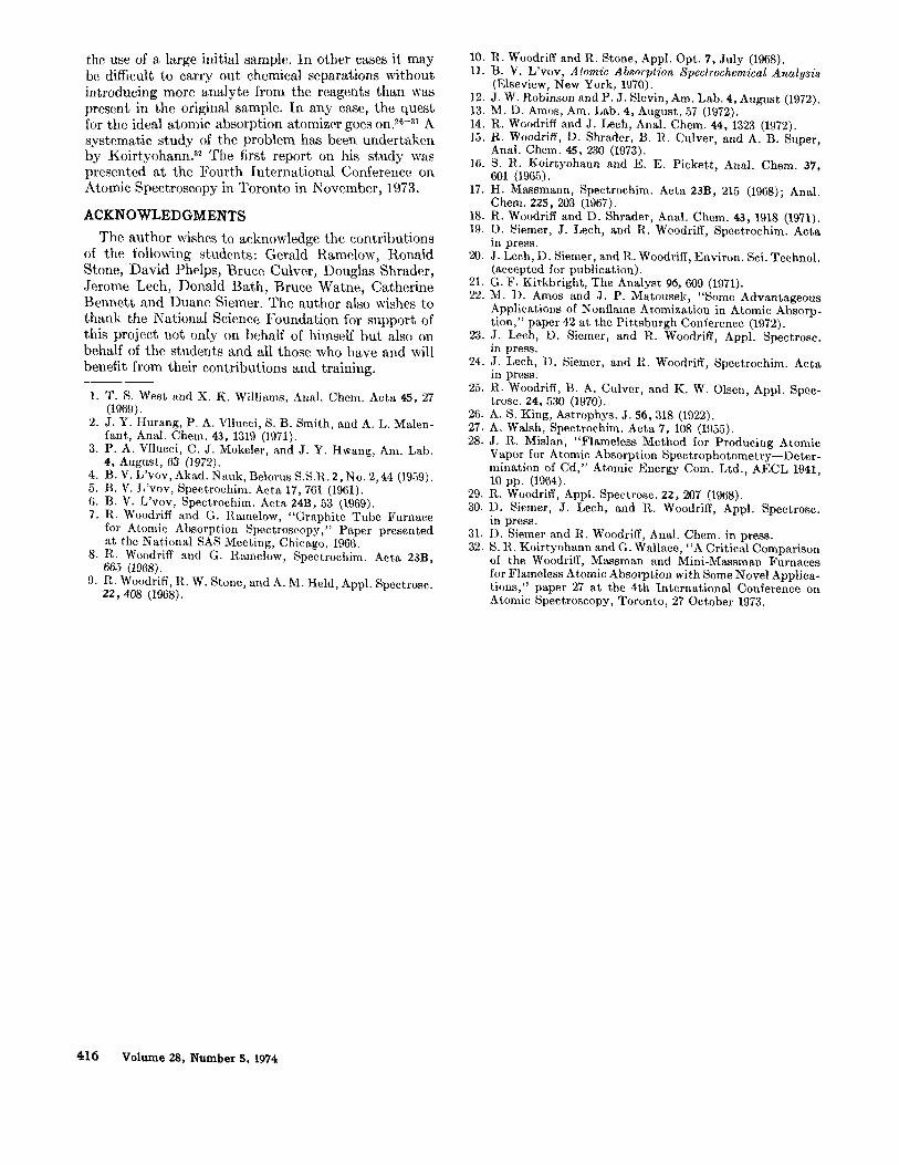
There are four kinds of tube furnaces which have received extensive experimental study. The first one to be reported was developed by L 'vov ~, 4-6 in Russia (Fig. 1). In this system the atomizer and five or six samples on the end of carbon rods are placed in a chamber which is evacuated. Then argon is introduced until the desired pressure (up to 8 or 9 atm) is reached. Next theatomizat ion tube is heated; then a carbon rod with the dried sample is inserted into a hole in the bot tom of the atomizer tube and the sample rod is heated by another power source. The sample evaporates and is confined to the light beam until it diffuses out of the ends of the tube. Tubes as small as 1.~9 mm inside diameter have been used, and L 'vov reported the best absolute sensitivity so far obtained.
Independently of L 'vov's work in Russia another furnace was developed at Montana State UniversityY -~ I t consists of a well insulated, constant temperature furnace operated at atmospheric pressure (Fig. i). The sample port has a constriction near the atomization tube which makes a seal with the rim of the sample crucible, or, if vertical sample introduction is used, the seal is made with the pedestal which is used to push the crucible up into the furnace. The latter arrangement allows the use of porous crucibles which are useful in the analysis of air particulates, etc. 3, 13-1~ An 18/7 Vycor ball joint is at tached to the outside of the en- trance port. The argon supply is introduced where the Vycor joint attaches to the furnace. When the Yycor tube is open, argon flows out because of the resistance to flow through the furnace. When a sample is inserted from the atmosphere, the escaping argon gas washes the oxygen off the crucible so tha t it can be inserted directly from the atmosphere. Unlike L 'vov 's system which used an auxiliary power supply to heat the sample, this system uses the heat of the furnace. The rate of heating depends on the heat capacity of the crucible, the rate of insertion, and the rate of heat transfer from the large furnace parts to the small crucible. Fluctuations in heating rate are not critical, provided the atomizer chamber is t ight and long. The fact tha t the sample is completely enclosed except for the two remote ends and also the fact tha t the readings are taken at essentially constant temperature do much to eliminate matrix effects except, of course, for back- ground absorption. Ordinarily this can be taken care of conveniently by the method of Koir tyohann and Pickett26
Volume 28, Number 5, 1974 APPLIED SPECTROSCOPY 413
o ~
(-'--7
~VOV
s lo ~/oodr;fff
C~
L_ i ....
C~
0 1 C~
M assr0 ~
FIG. 1. At6mizer chambers.
Massman, '7-'~ working in Germany, developed a tube atomizer. I t consists of a straight graphite tube of about 8 mminside diameter and 55 mm long with three holes in the top (Fig. 1). The sample is added to the cold tube with a pipet through the center hole. The tube is first gently heated to dry the sample, then more strongly heated to carbonize it, and, finally, atomized with a current of about 400 A. The atomizer tube is supported at the ends by water-cooled electrodes. This allows it to cool rapidly for the introduction of the next sample, but it also makes a thermal gradient down the tube when the tube is heated.
This is a convenient atomizer, especially when a few samples at a time are to be run, because no other drying or ashing facilities are needed. The advantage is not as great when large numbers of samples are to be run since, in the two previous systems, many samples can be placed in a tray, dried, and then ashed simultaneously followed by insertion of the rods or crucibles into the furnace for atomization. Also sometimes it is difficult to separate the ashing and volatilization steps without special conditions such as the use of a plasma asher. With mercury it is more convenient to ash the sample in a tube with oxygen, catch the mercury on a gold- plated porous crucible, and then place the crucible in the furnace for atomizationY, ,4, s0 Semienclosed atomizers of the Massman type are, in general, less affected by the matrix material than are open atomizers which depend entirely on the surrounding gas to con- fine the atom cloud.
The last type of carbon tube atomizer to be developed was the so-called carbon rod atomizer.', ~', 22 I t was
first reported by M. D. Amos and 3. P. Matousek at the Pittsburgh Conference in 1972. I t consists of a short length of carbon tube held between the ends of two carbon rods. I t is a clever, convenient little device and has many desirable features. Current passing from one rod to another through the tube heats the tube fairly uniformly. When samples are dried and car- bonized in the tube, the volatile material passes com- pletely out of the end of the tube rather than merely distilling to a colder part of the tube to reevaporate on the atomization cycle. There are three modes of opera- tion of the carbon rod atomizer. With a small hole in the middle of the atomizer tube to introduce samples with a pipet, it can be used exactly like the Massman atomizer. With the grooves in the ends of the holder rods turned in a vertical direction, a cup can be held between the rods. The absorption is generally measured through a small, transverse hole below the rim of the cup. This arrangement may be used with solid samples. A third arrangement for the atomizer is to use a hori- zontal tube without a hole in the top but to make the tube out of porous graphite} °, 2a. 24 Air or other gases containing suspended particulates such as lead can be filtered through the walls of the tube. The tube can then be placed between the carbon rods and the sample atomized• With this arrangement, unlike the furnace, some of the sample escapes through the walls of the atomizer without getting into the light beam. However, the fraction is usually constant, and the sensitivity of the method is so great that this is ordinarily not im- portant. For example, in most populated areas 100 or 200 cm ~ of air drawn through the crucible with a syringe are sufficient for a lead analysis.
A common measure of the sensitivity of nonflame devices is the so-called absolute sensitivity. This is the number of grams of pure element needed to give a 1% absorption. This kind of sensitivity varies inversely with the cross sectional area of the atomization cham- ber. If the cross sectional area of the atomizer tube is doubled, the light absorption and sensitivity will be cut in half. The absolute sensitivity is independent of the length of the tube, provided it is long enough so that all of the substance evaporates before the first part of it leaves the light path. Absolute sensitivity is a good criterion when sample size is extremely limited• How- ever, for real samples absolute sensitivity depends on the assumption that the sensitivity will be the same with the matrix material present as it will without it, and, furthermore, absolute sensitivity tells nothing about the sample capacity of the atomizer as a means of obtaining greater accuracy and relative sensitivity.
When reasonable size samples are available and matrix materials may influence sensitivity, chemists are often more interested in so-called relative sensitivity: the grams of substance detectable per gram of sample. The applicability of relative sensitivity is limited be- cause it depends on the nature of the matrix. How- ever, it bet ter expresses the usefulness of the device for real samples. The relative sensitivity of an atomizer is independent of the cross sectional area of the atomizer tube. This is because if the cross sectional area of the
414 Volume 28, Number S, 1974
tube is doubled, it will hold twice as much sample, and so the device will detect the same number of grams of analyte per gram of sample as before. On the other hand, the relative sensitivity is directly proportional to the length of the tube; if the length of the tube is doubled, it will hold twice as much sample.
The use of peak area instead of peak height ordinarily reduces errors caused by matrix material, which changes the rate of atomization. Also peak area measurements usually have a greater dynamic range. 11 Matrix ma- terials are more likely to modify the rate of analyte atom formation (to the extent that some leave before the last evaporate) than they are to modify the time the analyte atoms reside in the light path. When peak area is measured, the relative sensitivity increases with the cube of the path length of the atomizer. Thus, doubling the atomizer length increases the sensitivity eightfold.
By diffusion from the ends, the residence time of atoms in a tube is proportional to the square of the length of the tube, and, since the sample size which can be used is proportional to the length, the over-all relative sensitivity is proportional to the cube of the length. I t is hard to attain these conditions since with ordinary graphite a large part of the sample diffuses out through the walls of the tube or around the joints.
L 'vov found with studies using radioactive material in the cure t (atomization chamber or heater tube) that slightly more than half of the sample diffused through the walls of the chamber rather than out of the ends when using chambers 4.5- X 40-mm i.d. con- structed of good grade, uncoated spectrographic graphite. He also found that , with a pyrolitically coated tube with no transverse holes, essentially none of the sample diffused through the walls. When a transverse hole of 2 or 3 mm diameter was used for sample intro- duction, 20 to 40 % of the sample diffused out through it even though it was plugged with good uncoated graphite.
We find that better sensitivity is obtained when using uncoated graphite if channels are left through the seal between the crucible and the chamber for a slow flow of argon into the chamber. This is because the sample that diffuses back through the walls of the crucible is carried into the chamber by the argon flow. This is surely the wrong approach, but it illustrates the importance of diffusion through the walls of the crucible.
We find when using uncoated crucibles tha t in- dividual crucibles consistently give a very slightly higher or lower sensitivity, depending presumably on the seal they make with the atomization chamber and on the rate of diffusion through their walls. For very precise results they can be sorted and matched, or the vertical sample introduction system can be used where the pedestal on which the crucible rests makes the seal, thus eliminating the importance of the shape and porosity of the crucible.
The ideal atomic absorption atomizer would perhaps be one that would atomize the analyte independently of the presence o f a million or billion times as much complex matrix material. For example, if an atomic
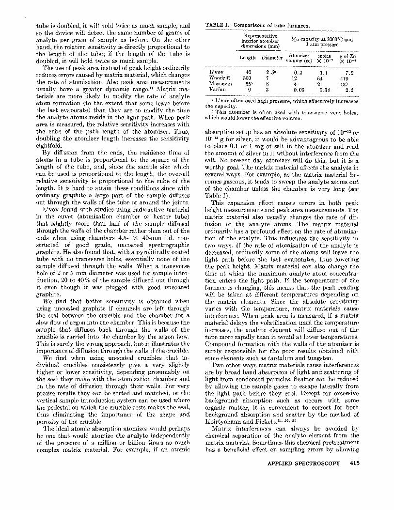
TABLE I. Comparisons of tube furnaces.
Representative interior atomizer dimensions (mm)
~~o capacity at 2000°C and 1 atm pressure
Length Diameter Atomizer moles g of Zn volume (cc) X 10 -7 × 10 -6
L'vov often used high pressure, which effectively increases ~he capacity.
b This atomizer is often used with transverse vent holes, which would lower the effective volume.
absorption setup has an absolute sensitivity of 10 -12 or 10 -15 g for silver, it would be advantageous to be able to place 0.1 or 1 mg of salt in the atomizer and read the amount of silver in it without interference from the salt. No present day atomizer will do this, but it is a worthy goal. The matrix material affects the analyte in several ways. For example, as the matrix material be- comes gaseous, it tends to sweep the analyte atoms out of the chamber unless the chamber is very long (see Table I).
This expansion effect causes errors in both peak height measurements and peak area measurements. The matrix material also usually changes the rate of dif- fusion of the analyte atoms. The matrix material ordinarily has a profound effect on the rate of atomiza- tion of the analyte. This influences the sensitivity in two ways. If the rate of atomization of the analyte is decreased, ordinarily some of the atoms will leave the light path before the last evaporates, thus lowering the peak height. Matrix material can also change the time at which the maximum analyte atom concentra- tion enters the light path. If the temperature of the furnace is changing, this means that the peak reading will be taken at different temperatures depending on the matrix elements. Since the absolute sensitivity varies with the temperature, matrix materials cause interference. When peak area is measured, if a matrix material delays the volatilization until the temperature increases, the analyte element will diffuse out of the tube more rapidly than it would at lower temperatures. Compound formation with the walls of the atomizer is surely responsible for the poor results obtained with some elements such as tantalum and tungsten.
Two other ways matrix materials cause interferences are by broad band absorption of light and scattering of light from condensed particles. Scatter can be reduced by allowing the sample gases to escape laterally from the light path before they cool. Except for excessive background absorption such as occurs with some organic matter, it is convenient to correct for both background absorption and scatter by the method of Koir tyohann and Pickett ." . iG. 25
Matrix interferences can always be avoided by chemical separation of the analyte element from the matrix material. Sometimes this chemical pretreatment has a beneficial effect on sampling errors by allowing
APPLIED SPECTROSCOPY 4 1 5
the use of a large initial sample. In other cases it may be difficult to carry out chemical separations without introducing more analyte from the reagents than was present in the original sample. In any case, the quest for the ideal atomic absorption atomizer goes on. 2~-3' A systematic study of the problem has been undertaken by Koirtyohann. 32 The first report on his study was presented at the Fourth International Conference on Atomic Spectroscopy in Toronto in November, 1973.
A C K N O W L E D G M E N T S
The author wishes to acknowledge the contributions of the following students: Gerald Ramelow, Ronald Stone, David Phelps, Bruce Culver, Douglas Shrader, Jerome Lech, Donald Bath, Bruce Watne, Catherine Bennett and Duane Siemer. The author also wishes to thank the National Science Foundation for support of this project not only on behalf of himself but also on behalf of the students and all those who have and will benefit from their contributions and training.
1. T. S. West and X. K. Williams, Anal. Chem. Acta 45, 27 (1969).
2. J. Y. Hurang, P. A. Vllucci, S. B. Smith, and A. L. Malen- rant, Anal. Chem. 43, 1319 (1971).
3. P. A. Vllucci, C. J. Mokeler, and J. Y. Hwang, Am. Lab. 4, August, 63 (1972).
4. B.V. L'vov, Akad. Nauk, Belorus S.S.R. 2, No. 2, 44 (1959). 5. B. V. L'vov, Spectrochim. Acta 17,761 (1961). 6. B. V. L'vov, Spectrochim. Acta 24B, 53 (1969). 7. R. Woodriff and G. Ramelow, "Graphite Tube Furnace
for Atomic Absorption Spectroscopy," Paper presented at the National SAS Meeting, Chicago, 1966.
8. R. Woodriff and G. Rmnelow, Spectrochim. Acta 23B, 665 (1968).
9. R. Woodriff, R. W. Stone, and A. M. Held, Appl. Spectrosc. 22,408 (1968).
10. R. Woodriff and R. Stone, Appl. Opt. 7, July (1968). 11. B. V. L'vov, Atomic Absorplion 8pectrochemical Analysis
(Elseview, New York, 1970). 12. J. W. Robinson and P. J. Slevin, Am. Lab. 4, August (1972). 13. M. D. Amos, Am. Lab. 4, August, 57 (1972). 14. R. Woodriff and J. Lech, Anal. Chem. 4.4, 1323 (1972). 15. R. Woodriff, D. Shrader, B. R. Culver, and A. B. Super,
Anal. Chem. 45,230 (1973). 16. S. R. Koirtyohann and E. E. Pickett, Anal. Chem. 37,
Chem. 225,203 (1967). 18. R. Woodriff and D. Shrader, Anal. Chem. 43, 1918 (1971). 19. D. Siemer, J. Lech, and R. Woodriff, Spectrochim. Acta
in press. 20. J. Lech, D, Siemer, and R. Woodriff, Environ. Sci. Technol.
(accepted for publication). 21. G. F, Kirkbright, The Analyst 96, 609 (1971). 22. M. ]). Amos and J. P. Matousek, "Some Advantageous
Applications of Nonflame Atomization in Atomic Absorp- tion," paper 42 at the Pittsburgh Conference (1972).
23. J. Lech, D. Siemer, and R. Woodriff, Appl. Spectrosc. in press.
24. J. Lech, D. Siemer, and R. Woodriff, Spectrochim. Acta in press.
25. R. Woedriff, B. A. Culver, and K. W. Olsen, Appl. Spec- trosc. 24,530 (1970).
26. A. S. King, Astrophys. J. 56,318 (1922). 27. A. Walsh, Spectrochim. Acta 7, 108 (1955). 28. J. R. Mislan, "Flameless Method for Producing Atomic
Vapor for Atomic Absorption Spectrophotometry--Deter- mination of Cd," Atomic Energy Com. Ltd., AECL 1941, 10 pp. (1964).
29. R. Woodriff, Appl. Spectrosc. 22,207 (1968). 30. D. Siemer, J. Lech, and R. Woodriff, Appl. Spectrose.
in press. 31. D. Siemer and R. Woodriff, Anal. Chem. in press. 32. S. R. Koirtyohann and G. Wallace, "A Critical Comparison
of the Woodriff, Massman and Mini-Massman Furnaces for Flameless Atomic Absorption with Some Novel Applica- tions," paper 27 at the 4th International Conference on Atomic Spectroscopy, Toronto, 27 October 1973.