222
ATTACHMENT ComEd Response to NRC RAI Section 3 I 4.2, "Instrumentation" · -=- k:\nla\quad\tsup\raicov32.wpf -- 1 . i PDR ADOCK 05000237 t P PDR 1-'-;... -·· - -- - - i

ATTACHMENT
ComEd Response to NRC RAI
Section 3 I 4.2, "Instrumentation"
· -=- k:\nla\quad\tsup\raicov32.wpf --1 . i r-~-·=·i9~·s_o_a-10_0_1_a_9_9_s_o_a_o_4~~~-;---;-~-.~1
~ PDR ADOCK 05000237 t ~ P PDR 1-'-;... -·· - -- - -i

·-
Attachment Commonwealth Edison
RAJ Response TSUP3/4.2
Instrumentation
Generic Questions
1. In review of proposed Technical Specification Upgrade Program (TSUP) Section 3.2, the No Significant Hazards Consideration for this application is not completely accurate and the wording used in the evaluations are confusing. The considerations did not take into account the relaxation of the current Technical Specification (TS) requirement with the adoption of the proposed Standard Technical Specifications (STS). In addition, the staff discovered typographical errors in the considerations. The staff requests that Commonwealth Edison Company (ComEd) re-evaluate the No Significant Hazards-Consideration for the application and supplement the application by providing an accurate and complete No Significant Hazards Consideration.
ComEd Response: This is provided in Enclosure 1.
2. In review of proposed TSUP Section 3.2 ComEd did not evaluate and provide justification for the relaxations and deviations between current TS requirements and the proposed TS. ComEd has compared only the proposed TS to the STS and provided justification for any deviations. To allow the staff to perform a complete and accurate review of the above proposed TSUP TS sections, please provide supplemental evaluations of any changes or deviations between the current TS and the proposed TS. In addition, for each deviation or relaxation between the current TS and the proposed TS an evaluation should be provided which demonstrates that the proposed TS maintains the current licensing basis as described in the Updated Final Safety Analysis Report.
ComEd Response:
A) Administrative Changes
ComEd has revised the current Dresden and Quad Cities TS (CTS) to incorporate non-technical, administrative changes into the TSUP section 3/4.2 (Instrumentation). The proposed changes to the Dresden and Quad Cities CTS are based upon the accepted NRC Standard Technical Specifications (BWR-STS), contained in NUREG-0123, Revision 4 "Standard Technical Specifications General Electric Plants BWR/ 4." These administrative changes are intended to incorporate human factor principles into the form and structure of the TS so that they would be easier to use for plant operation's personnel. These changes are editorial in nature or involve the reorganization or reformatting of requirements without affecting technical content of the current TS or operational requirements. Therefore, these are administrative changes to the CTS, and do not represent a relaxation of the CTS. Examples of these administrative changes include:
1.
2.
3. 4.
5.
Clarification of applicability to specific modes (as referenced in the associated instrumentation tables); Addition of unambiguous Action statements within the LCO; the capitalization of definitionspecific nomenclature (i.e. CHANNEL and TRIP SYSTEM); Revision of the BWR-STS numbering system (i.e. LCO, SR, and Table numbers); Relocation of certain requirements to other documents (i.e. Offsite Dose Calculation Manual -
-ODCM; UFSAR; and procedures); Incorporation of clarified BWR-STS and plant-specific terminology (i.e. proposed
k: \nla\quad\tsup \rair32 _r1.wpf Page 1
•
••
Attachment Commonwealth Edison
RAJ Response TSUPJ/4.2
Instrumentation
"OPERATIONAL MODE" versus "OPERATIONAL CONDITION" and proposed "Main Steam Line Tunnel Temperature - High" versus the CTS nomenclature "High temperature main steamline tunnel).
These administrative changes do not represent a relaxation of the current requirements or licensing basis, as defined in the UFSAR. The equipment and instrumentation used to meet the requirements defined in the TSUP have not changed, and are equivalent to the new description. Therefore, the proposed nomenclature represents an administrative change, and as such, is not a relaxation of the CTS.
B) Dresden and Quad Cities CTS LCOs and Applicability Requirements
The Dresden and Quad Cities CTS contain Applicability and Objective statements at the beginning of TS Section 3/4.2 and 3.2/4.2 (Instrumentation). These statements are generic in nature and do not provide any useful information to the user of the technical specifications. The proposed changes delete the Objective statement and clarify Limiting Condition for Operation (LCO) and Applicability requirements for each functional group of instruments (i.e. Isolation Actuation, ECCS Actuation, etc.). The applicable mode for each instrument is specified in the associated TSUP instrumentation table. This is consistent with BWR-STS format and provides a more user-friendly, and unambiguous presentation of requirements for the instrumentation systems at Dresden and Quad Cities. These proposed changes represent a more conservative operating practice, and therefore are not a relaxation of the CTS.
1. Dresden and Quad Cities CTS 3.2.A; Primary Containment Isolation Functions
Dresden and Quad Cities CTS 3.2.A (and associated CTS Table) delineates the LCO requirement for Primary Containment Isolation functions, including instrumentation for isolation of the Main Steam Lines, the Reactor Core Isolation Cooling (RCIC) system (Quad Cities only), the Isolation Condenser system (Dresden only), and the High Pressure Coolant Injection (HPCI) system. These CTS requirements have been incorporated into TSUP 3.2.A, "Isolation Actuation," (and associated Table 3.2.A-1). The TSUP requires operability of specified Isolation Actuation instrumentation as listed in Table 3.2.A-1, with minimum operable channels, applicable operational modes, and associated trip setpoints. The CTS requirement has been renamed to the BWR-STS nomenclature of "Isolation Actuation." This is an administrative change to the CTS, and as such does not represent a relaxation of the CTS. The instrumentation used to monitor the parameter has not changed, and is equivalent to the BWRSTS nomenclature.
In addition to the instrumentation requirements for Primary Containment Isolation, the TSUP 3.2.A (and Table 3.2.A-1) has also explicitly defined, in separate sections of Table 3.2.A-1, the instrumentation requirements for the isolation of Secondary Containment (also see Item B.4 -Refueling Floor Radiation Monitors below), the Reactor Water Cleanup (RWCU) system, the RCIC system (Quad Cities only), the Isolation Condenser system (Dresden only), the HPCI system, and the Shutdown Cooling system (RHR Shutdown Cooling Mode at Quad Cities). This is consistent with BWR-STS format, and represents a more clear and unambiguous delineation of requirements for isolation actuation instrumentation. Therefore, the modified format does not represent a relaxation of CTS .
TSUP 3.2.A is consistent with the Dresden and Quad Cities CTS requirements, and is equivalent to BWR-STS 3.3.2, except as described in items C. and D. below. Therefore, the TSUP does not
k:\nla\quad\tsup \rair32 _r1.wpf Page2

represent a relaxation of the CTS.
Attachment Commonwealth Edison
RAJ Response TSUP 3/4.2
Instrumentation
2. Dresden and Quad Cities CTS 3.2.B; Core and Containment Cooling Systems
Dresden and Quad Cities CTS 3.2.B (and associated CTS Table) delineates the LCO requirement for the initiation and control functions of Core and Containment Cooling System instrumentation. These CTS requirements have been incorporated into TSUP 3.2.B, "Emergency Core Cooling Systems (ECCS) Actuation" (and associated Table 3.2.B-1). The TSUP requires operability of specified ECCS actuation instrumentation as listed in Table 3.2.B-1, with minimum operable channels, applicable operational modes, and associated trip setpoints. The CTS requirement also states that the instrumentation must be operable when the system(s) it initiates are required to be operable.
The CTS requirement has been renamed to the BWR-STS nomenclature. This is an administrative change to the CTS, and as such does not represent a relaxation of the CTS. The instrumentation used to monitor the parameter has not changed, and is equivalent to the BWRSTS nomenclature.
TSUP 3.2.B is consistent with the Dresden and Quad Cities CTS requirements, and is equivalent to BWR-STS 3.3.3, except as described in items C. and D. below. The CTS requirement for operability of instrumentation when the initiated system is required to be operable has been incorporated into the "Applicable Operational Mode" column of TSUP Table 3.2.B-1.
3. Dresden and Quad Cities CTS 3.2.C; Control Rod Block Actuation
i. Dresden CTS 3.2.C.1 and Quad Cities CTS 3.2.C.l
Dresden and Quad Cities CTS 3.2.C.1 (and associated CTS Table) delineates the LCO requirement for Control Rod Block Actuation instrumentation. These CTS requirements have been incorporated into TSUP 3.2.E (and associated Table 3.2.E-1). The TSUP requires operability of control rod block instrumentation as listed in Table 3.2.E-1, with minimum operable channels, applicable operational modes, and associated trip setpoints. TSUP 3.2.C.1 is consistent with the Dresden and Quad Cities CTS requirements, and is equivalent to BWR-STS 3.3.6, except as described in items C. and D. below.
11. Dresden CTS 3.2.C.2 and Quad Cities CTS 3.2.C.2
Dresden and Quad Cities CTS 3.2.C.2 provides a relaxation (with a time limitation) from the minimum operable channel requirements for the rod block monitor during maintenance or testing. This has been deleted from the TSUP. The CTS requirement is not consistent with BWR-STS guidance, and the deletion of the less stringent requirement represents a more conservative operating practice. Therefore the deletion of CTS 3.2.C.2 does not represent a relaxation of CTS.
4. Dresden and Quad Cities CTS 3.2.D; Refueling Floor Radiation Monitors
1. Dresden and Quad Cities CTS 3.2.D.1
Dresden and Quad Cities CTS 3.2.D.1 delineates the operability, applicability, and minimum channel requirements for the Refueling Floor Radiation Monitors. These CTS
k:\nla\quad\tsup\rair32_r1.wpf Page3
•
•
11.
Attachment Commonwealth Edison
RAJ Response TSUP3/4.2
Instrumentation
requirements have been incorporated into TSUP Table 3.2.A-1, Item 2.d, "Refueling Floor Radiation - High." The proposed operability and minimum channel requirements in Table 3.2.A-1, Item 2.d are consistent with the CTS requirements. TSUP 3.2.D.1 is consistent with the Dresden and Quad Cities CTS requirements, and is equivalent to BWR-STS Table 3.3.2-1, Item 2.e, except as described below and in items C. (Response Time LCO and Surveillance Requirements) and D. (Instrumentation Trip Setpoints).
The CTS requirement has been renamed for clarification and consistency with BWR-STS nomenclature. This is an administrative change to the CTS, and as such does not represent a relaxation of the CTS. The instrumentation used to monitor the parameter has not changed, and is equivalent to the BWR-STS nomenclature.
The CTS applicability has been revised from "whenever irradiated fuel or components are present in the fuel storage pool and during refueling or fuel movement operations" to Operational Modes 1, 2, 3 and ** (i.e. when handling irradiated fuel in the secondary containment). This applicability is equivalent to the BWR-STS applicability {NUREG 0123 and NUREG 1433). The current applicability would require operability of both monitors at all times, given that there is always irradiated fuel in the spent fuel pools. The implied CTS action with one of the two required monitors inoperable, would be to halt all fuel movement operations. The proposed TSUP applicability during the handling of irradiated fuel in the secondary containment is consistent with the CTS applicability, and is an administrative enhancement of the CTS requirements. The TSUP applicability provides a clear and unambiguous delineation of requirements, and is not a relaxation of CTS.
Dresden and Quad Cities CTS 3.2.D.2
Dresden and Quad Cities CTS 3.2.D.2 specifies the allowable outage time (AOT) and required action for an inoperable channel (one of two refueling floor radiation monitors). This CTS AOT and action have been replaced by TSUP 3.2.A, Action 3, and Table 3.2.Al, Action 24. TS 3.2.A, Action 3 states that if the minimum operable channels is less than required for both trip systems, then one trip system shall be placed in the tripped condition within one hour, and the actions specified in the table implemented. Table 3.2.A-l, Action 24 requires establishment of secondary containment within one hour (with the standby gas treatment system operating). The CTS allows 24 hours prior to establishing secondary containment. The proposed actions are more conservative than the CTS in that if a refueling floor radiation monitor is found inoperable, the trip system will be tripped within one hour, and secondary containment established within two hours. Therefore the TSUP provisions are not a relaxation of the CTS.
m. Dresden and Quad Cities CTS 3.2.D.3
lV.
Dresden and Quad Cities CTS 3.2.D.3 specifies the trip setpoint for the refueling floor radiation monitors. This has been relocated to TSUP Table 3.2.A-l, Item 2.d, column 2. The TSUP provisions are equivalent to the CTS. Therefore, the TSUP provisions are not a relaxation of the CTS .
Dresden and Quad Cities CTS 3.2.D.4
Dresden and Quad Cities CTS 3.2.D.4 specifies the required action for two inoperable
k:\nla\quacl\tsup \rair32 _r1.wpf Page4

Attachment Commonwealth Edison
RAJ Response TSUP3/4.2
Instrumentation
channels (both refueling floor radiation monitors). This CTS action requires immediate isolation of secondary containment and standby gas treatment system operation. The CTS action has been replaced by TSUP 3.2.A, Action 3, and Table 3.2.A-1, Action 24. TS 3.2.A, Action 3 states that if the minimum operable channels is less than required for both trip systems, then one trip system shall be placed in the tripped condition within one hour, and the actions specified in the table implemented. Table 3.2.A-1, Action 24 requires establishment of secondary containment within one hour (with the standby gas treatment system operating). This is equivalent to BWR-STS Table 3.3.2-1 Action 26. The TSUP represents a rela.Xation of the CTS, in that the TSUP allow one hour prior to tripping the trip system (which will automatically establish secondary containment and actuate the standby gas treatment system). However, the proposed change does not represent a significant reduction in safety. The extended period (one hour) to establish secondary containment is consistent with similar plant Technical Specification provisions and NRC-approved requirements (BWR-STS). The one-hour completion time is intended to allow the operator time to evaluate and repair any discovered inoperabilities. The one-hour period is acceptable because it minimizes risk while allowing time for restoration or
tripping of channels.
5. Dresden and Quad Cities CTS 3.2.E; Post Accident Instrumentation
Dresden and Quad Cities CTS 3.2.E (and associated CTS tables) delineates the LCO requirement for post accident monitoring instrumentation. This CTS requirement has been incorporated into TSUP 3.2.F, "Accident Monitoring" (and associated Tables 3.2.F-1). The CTS requirement has been renamed to the BWR-STS nomenclature. This is an administrative change to the CTS, and as such does not represent a relaxation of the CTS. The instrumentation used to monitor the parameter has not changed, and is equivalent to the BWR-STS nomenclature.
TSUP 3.2.F is consistent with the Dresden and Quad Cities CTS requirements. Therefore, the TSUP does riot represent a relaxation of the CTS.
6. Dresden CTS 3/4.2.F and 3/4.2.G; Quad Cities CTS 3/4.2.G and 3/4.2.H; Radioactive Liquid Effluent Instrumentation and Radioactive Gaseous Instrumentation
Dresden CTS 3/ 4.2.F and Quad Cities CTS 3/ 4.2.G (and associated CTS tables - Dresden CTS Tables 3.2.4 and 4.2.2; Quad Cities CTS Tables 3.2-5, and 4.2-2) delineate the LCO requirements and actions for the Radioactive Liquid Effluent Instrumentation. Dresden CTS 3.2.G and Quad Cities CTS 3.2.H (and associated CTS tables - Dresden CTS Tables 3.2.5 and 4.2.3; Quad Cities CTS Tables 3.2-6, 4.2-3, and the applicable item in 4.2-1) delineate the LCO requirements and actions for the Radioactive Gaseous Effluent Instrumentation. These requirements have been relocated to the Offsite Dose Calculation Manual (ODCM) for each station, in accordance with the guidance provided in Generic Letter 89-01, "Implementation of Programmatic Controls for Radiological Effluent Technical Specifications in the Administrative Controls Section of the Technical Specifications and the Relocation of Procedural Details of RETS to the Off site Dose Calculation Manual or to the Process Control Program."
i. Dresden ODCM Tables 12.2-1 and 12.2-2 do not include the Dresden CTS requirements and associated Action for "Tank Level Indicating Devices" (Tables 3.2.4 and 4.2.2). These requirements were inadvertently omitted from the Dresden ODCM, and will be added as part of the next annual ODCM update.
k:\nla\quad\tsup\rair32_r1.wpf ·Page 5

Attachment Commonwealth Edison
RAJ Response TSUP3/4.2
Instrumentation
11. Dresden ODCM Tables 12.2-3 and 12.2-4 do not include the Dresden CTS requirements and associated Action for "Off-Gas Radiation Monitor" (Tables 3.2.5 and 4.2.3). These requirements were inadvertently omitted from the Dresden ODCM, and will be added as part of the next annual ODCM update.
111. Dresden ODCM Tables 12.2-3 and 12.2-4 do not include the Dresden CTS requirements for the following instruments:
MVRS Process Exhaust Radiation Monitor MVRS Process Exhaust Particulate Sampler MVRS Process Exhaust Iodine Sampler MVRS Process Exhaust Particulate Sampler
These monitoring instruments were added to the Dresden CTS by Amendments 93/88 in order to utilize a Mobile Volume Reduction System (MVRS) for the treatment of licensed material by incineration . This system was never installed nor made operational at Dresden Station, nor is it planned for installation. Based upon this information, the radiation monitoring instruments associated with the MVRS are no longer applicable for Dresden Station. Therefore, the deletion of these monitoring instrument requirements does not represent a reduction in safety or a relaxation of the CTS.
7. Quad Cities CTS 3.2.F; Control Room Ventilation System Isolation
1. Quad Cities CTS 3.2.F.1 describes the process variable instrumentation that isolates the Control Room Ventilation System (high drywell pressure, low water level, high main steamline flow, high toxic gas concentration, high radiation in either of the reactor building exhaust ducts, and manual isolation). This description has not been retained in the TSUP, as it provides design information more suited for owner-controlled documents (i.e. UFSAR). Therefore, the deletion of the description does not represent a relaxation of CTS.
Quad Cities CTS 3.2.F.1 also delineates the LCO requirement for the Control Room Ventilation System isolation instrumentation. This is accomplished by referencing CTS Table 3.2-1 (Primary Containment Isolation Instrumentation); CTS 3.2.H (Radioactive Gaseous Effluent Instrumentation); and CTS 3.2.F.2.
CTS Table 3.2-1 defines the required instrumentation for Control Room Ventilation system isolation by referencing a modifying footnote for each of the applicable instruments (high drywell pressure, low water level, and high main steamline flow). This footnote [Quad Cities CTS Table 3.2-1, note (5)] states that the modified instrumentation also isolates the control room ventilation system. The applicable instruments in Quad Cities CTS Table 3.2-1 do not include high radiation in either of the reactor building exhaust ducts, high toxic gas concentration, and manual isolation. The instrumentation requirements for high toxic gas concentration are discussed in Quad Cities CTS 3.2.F.2. The instrumentation requirements for high radiation in either of the reactor building exhaust ducts are defined in CTS 3.2.H and CTS Table 3.2-6.
The instrumentation requirements in Quad Cities CTS Table 3.2-1 [as modified by CTS note (5)] are incorporated into the proposed Quad Cities TSUP [TSUP Table 3.2.A-1, as modified by proposed note (k)]. TSUP Table 3.2.A-1, note (k) modifies Items 2.a (Reactor
k:\nla\quad\tsup\rair32_r1.wpf Page6
•
Attachment Commonwealth Edison
RAJ Response TSUP3/4.2
Instrumentation
Vessel Water Level - Low); 2.b (Drywell Pressure - High); 2.c (Reactor Building Ventilation Exhaust Radiation - High); 2.d (Refueling Floor Radiation - High); and 3.d (Main Steam Line Flow - High). TSUP note (k) is equivalent to CTS note (5). TSUP Table 3.2.A-1 requirements for Control Room Ventilation system isolation instrumentation are equivalent to CTS requirements. Therefore the TSUP requirements do not represent a relaxation of the CTS.
In addition, TSUP Table 3.2.A-1 provides Control Room Ventilation system isolation instrumentation requirements for the refueling floor radiation monitors (item 2.d -Refueling Floor Radiation - High). This provides additional requirements to the CTS requirements, and is therefore more conservative than the CTS.
11. Quad Cities CTS 3.2.F.2 delineates the LCO and setpoint for the toxic gas detection system (ammonia analyzer). The CTS also states that the provisions of Specification 3.0.A are not applicable. These requirements have been incorporated into proposed Quad Cities TSUP 3.2.K, "Toxic Gas Monitoring."
TSUP incorporates the CTS requirements, and enhances the CTS by specifically stating the applicability and required actions. Since the required actions are explicitly stated in TSUP 3.2.K, the CTS statement that the provisions of Specification 3.0.A are not applicable has not been retained. This does not represent a relaxation of CTS .
8. Dresden CTS 3.2.H - Recirculation Pump Trip Initiation; Quad Cities TSUP 3.2.C - ATWS -RPT
Dresden CTS 3.2.H (and associated Dresden CTS Table 3.2.7) delineates the LCO requirements for the recirculation pump trip system. These requirements have been incorporated into TSUP (for both Dresden and Quad Cities) 3.2.C, "ATWS - RPT" (and associated TSUP Table 3.2.C-1). This is a new requirement with respect to the Quad Cities CTS.
The CTS requirement has been renamed to the BWR-STS nomenclature. This is an administrative change to the Dresden CTS. As such, the proposed TSUP requirements do not represent a relaxation of the CTS. The instrumentation used to monitor the parameter has not changed, and is equivalent to the BWR-STS nomenclature.
TSUP 3.2.C is consistent with the Dresden CTS requirements and BWR-STS 3.3.4.1, "ATWS Recirculation Pump Trip System Instrumentation."
Dresden CTS Table 3.2.7 requirements have been incorporated into TSUP Table 3.2.C-1 except as described below:
1. The Dresden CTS Table 3.2.7 Trip Functions have been renamed to the BWR-STS nomenclature. This is an administrative change to the Dresden CTS. As such, the proposed changes do not represent a relaxation of the CTS. The instrumentation used to monitor the parameter has not changed, and is equivalent to the BWR-STS nomenclature.
11. The CTS Table action statement has been relocated and incorporated into TSUP 3.2.C, Actions J, 2, 3, 4, and 5. _ These actions- represent a revision-of the existing-action requirement, and are consistent with the plant-specific design and the actions for Grand Gulf.
k:\nla\quad\tsup \rair32 _rl.wpf Page 7

Attachment Commonwealth Edison
RAJ Response TSUP3/4.2
Instrumentation
The proposed format is consistent with BWR-STS format, and represents a more clear and unambiguous delineation of requirements for isolation actuation instrumentation. Therefore, the relocation does not represent a relaxation of CTS. The proposed Actions are consistent with BWR-STS, as modified for plant-specific design and previously approved requirements. Therefore, the proposed actions are not a significant reduction in the margin of safety.
1v. The CTS Table 3.2.7 applicability requirements have been relocated and incorporated into TSUP 3.2.C, Applicability. In addition, CTS Table 3.2.7, note (d), which defines "RUN MODE" as "MODE 1" has been deleted. This is consistent with BWR-STS format, and represents a clear and unambiguous delineation of requirements for isolation actuation instrumentation. Therefore, the proposed changes do not represent a relaxation of CTS.
v. The CTS Table 3.2.7 setpoint for "High Reactor Pressure" has been revised from "greater than or equal to 1230 psig and less than or equal to 1250 psig" to "less than or equal to 1250 psig." The lower bound of the CTS setpoint ("greater than or equal to 1230 psig"), is designed to prevent inadvertent trips, and as such has no automatic protection function. Therefore this value is unnecessary in the LCO, and are more appropriate for relocation to owner-controlled procedures. Changes to the acceptance criteria detailed in procedures will continue to be controlled by the provisions of 10 CPR 50.59. This deviation from BWR-STS guidelines is an administrative change, and therefore is not a significant reduction in safety.
C) Response Time LCO and Surveillance Requirements
The BWR-STS requirements for Instrument System Response Times (3.3.2, Table 3.3.2-3 and 3.3.3, Table 3.3.3-3) and the corresponding BWR-STS response time surveillance requirements (4.3.2.2 and 4.3.3.3) have not been incorporated into TSUP sections 3/4.2.A (Isolation Actuation) and 3/4.2.B (ECCS Actuation). These requirements are not in the CTS. In addition, the NRC has approved (by SER dated December 28, 1994 for Licensing Topical Report NED0-32291, "System Analyses for Elimination of Selected Response Time Testing Requirements") and recommended (Generic Letter (GL) 93-08, "Relocation of Technical Specification Tables of Instrument Response Time Limits") the relocation of selected Response Time Testing requirements from the TS to the FSAR. Based upon current requirements, the NRC SER, and GL 93-08, the current licensing basis is maintained, and the TSUP provisions do not represent a relaxation of the CTS.
D) Instrumentation Trip Setpoints
The BWR-STS requirements for trip setpoints have been incorporated into the applicable instrumentation system LCO tables (as listed below). TSUP relocates the setpoint values from a separate BWR-STS setpoint table to the LCO table for each applicable instrumentation system (also listed below).
Instrumentation System
Isolation Actuation ECCS Actuation ATWS-RPT RCIC Actuation (Quad Cities only)
k:\nla\quad\tsup\rair32_r1.wpf
BWR-STS
3.3.2; Table 3.3.2-2 3.3.3; Table 3.3.3-2 3.3.4.1; Table 3.3.4.1-2
3.3.5; Table 3.3.5-2
Page 8
3.2.A; Table 3.2.A-1 3.2.B; Table 3.2.B-1 3.2.C; Table 3.2.C-1
3.2.D; Table 3.2.D-1
Isolation Condenser (Dresden only) Control Rod Block Suppression Chamber and Drywell Spray Actuation Feedwater Pump Trip
NIA 3.3.6; Table 3.3.6-2
3.3.9; Table 3.3.9-2 3.3.9; Table 3.3.9-2
·Attachment Commonwealth Edison
RAJ Response TSUP3/4.2
Instrumentation
3.2.D; Table 3.2.D-l 3.2.E; Table 3.2.E-1
3.2.I; Table 3.2.I-1 3.2.J: Table 3.2.J-1
TSUP incorporates the "Allowable Values" column of the applicable BWR-STS table (BWR-STS column 3) as the "Trip Setpoint" (TSUP column 2), and has not incorporated the "Trip Setpoint" column (BWR-STS column 2) and values. The specific values for "Trip Setpoint" in TSUP are consistent with the safety analysis for Dresden and Quad Cities Stations.
The TSUP "Trip Setpoint" column and values are equivalent to the CTS term "Trip Setting," which is equivalent to the BWR-STS "Allowable Values."
The BWR-STS requirements for "Trip Setpoint" have not been adopted in the TSUP. This deviation from BWR-STS guidelines maintains consistency with current Technical Specification requirements. The BWR-STS "Trip Setpoint" defines requirements which are necessary as a result of channel-specific drift characteristics, as opposed to a safety analysis value which actuates a protective function. The values which have not been incorporated into the TSUP (BWR-STS "Trip Setpoint") represent information related to system design, purpose, and operation. Therefore these values are unnecessary in the LCO, and are more appropriate for relocation to owner-controlled procedures. Changes to the acceptance criteria detailed in procedures will continue to be controlled by the provisions of 10 CPR 50.59. This deviation from BWR-STS guidelines is an administrative change, and therefore is not a significant reduction in safety.
E) BWR-STS LCOs not Incorporated in TSUP
1. Non-applicable Instrumentation
The BWR-STS instrumentation specifications (and associated tables) listed below have not been incorporated into the TSUP. These requirements are not in the CTS, and are not part of the plant design for Dresden and Quad Cities Stations. This deviation from BWR-STS guidelines is an administrative change, and therefore, is not a significant reduction in safety.
Instrumentation System
End-of-Cycle Recirculation Pump Trip Remote Shutdown Monitoring Chloride Intrusion Monitors Loose Part Detection System Turbine Overspeed Protection System
2. Owner-Controlled Documents
BWR-STS
3.3.4.2 3.3.7.4 3.3.7.9 3.3.7.11 3.3.8
The BWR-STS instrumentation specifications (and associated tables) listed below have not been incorporated into the TSUP. These requirements are not in the CTS, and are more appropriate for owner-controlled documents. This deviation from BWR-STS guidelines is an administrative change, and therefore, is not a significant reduction in safety.
k:\nla\quad\tsup\rair32_r1.wpf Page 9
Instrumentation System
Seismic Monitoring Meteorological Monitoring Fire Detection Instrumentation
G) Generic Letter 87-09 Guidance
BWR-STS
3.3.7.2 3.3.7.3 3.3.7.10
Attachment Commonwealth Edison
RAJ Response TSUP 3/4.2
Instrumentation
The STS action provisions which delineate a TS 3.0.4 exception are not incorporated into the TSUP. This is consistent with the guidance of Generic Letter 87-09. Therefore, this does not represent a relaxation of the CTS.
H) CTS Surveillance Requirements (SRs)
1. Dresden and Quad Cities CTS 4.2.A; Primary Containment Isolation Functions
Dresden and Quad Cities CTS 4.2.A delineate the surveillance requirements (SRs) for the instrumentation which actuates Primary Containment Isolation functions. The CTS SR also -references an associated CTS Table. This CTS table also includes instrumentation for isolation of the Main Steam Lines, the Reactor Core Isolation Cooling (RCIC) system (Quad Cities only), the Isolation Condenser system (Dresden only), and the High Pressure Coolant Injection (HPCI) system. This additional instrumentation is consistent with the corresponding CTS LCO table. The CTS SR and associated table has been incorporated into TSUP 4.2.A.1 (and associated TSUP Table 4.2.A-1).
TSUP 4.2.A.1 is equivalent to CTS 4.2.A and BWR-STS 4.3.2.1, with the exception that the CTS requirement for a logic system functional test [CTS 4.2.A and Quad Cities CTS Table 4.2-1, note (7)] has been relocated to TSUP 4.2.A.2. This provides an explicit surveillance requirement and frequency for a logic system functional test, and is consistent with the format and content of BWR-STS 4.3.2.2. The relocation and clarification of the logic system functional test requirement in CTS 4.2.A is administrative, and does not represent a relaxation of CTS.
2. Dresden and Quad Cities CTS 4.2.B; Core and Containment Cooling Systems - Initiation and Control
Dresden and Quad Cities CTS 4.2.B delineate the surveillance requirements (SRs) for the initiation and control instrumentation associated with the Core and Containment Cooling Systems. The CTS SR also references the associated CTS Table. The CTS SR has been incorporated into TSUP 4.2.B.1 (and associated TSUP Table 4.2.B-1).
TSUP 4.2.B is equivalent to CTS 4.2.B and BWR-STS 4.3.3.1, with the exception that the CTS requirement for a logic system functional test [CTS 4.2.B and Quad Cities CTS Table 4.2-1, note (7)] has been relocated to TSUP 4.2.B.2. This provides an explicit surveillance requirement and frequency for a logic system functional test, and is consistent with the format and content of BWR-STS 4.3.3.2. The relocation and clarification of the logic system functional test requirement in CTS 4.2.A is administrative, and does not represent a relaxation of CTS.
3. Dresden and Quad Cities CTS 4.2.C; Control Rod Block Actuation
Dresden and Quad Cities CTS 4.2.C delineate the surveillance requirements (SRs) for the
k:\n/a\quad\tsup \rair32 _r1.wpf Page 10

Attachment Commonwealth Edison
RAJ Response TSUP3/4.2
Instrumentation
instrumentation which actuates the control rod blocks. The CTS SR also references the associated CTS Table. The CTS SR has been incorporated into TSUP 4.2.E (and associated TSUP Table 4.2.E-1). TSUP 4.2.E is equivalent to CTS 4.2.C and BWR-STS 4.3.6. Therefore the proposed change does not represent a relaxation of the CTS.
4. Dresden and Quad Cities CTS 4.2.D; Refueling Floor Radiation Monitors
Dresden and Quad Cities CTS 4.2.D delineates the surveillance requirements (SRs) for the Refueling Floor Radiation Monitors. The CTS SR references the associated CTS table for the specific instrument surveillance requirements. These CTS instrument surveillance requirements have been incorporated into TSUP Table 4.2.A-l, Item 2.d, "Refueling Floor Radiation - High." The relocation of the CTS SR for the refueling floor radiation monitors is consistent with BWRSTS format, and does not represent a relaxation of CTS.
CTS 4.2.D also requires isolation of Reactor Building Ventilation (secondary containment isolation dampers) and initiation of the standby gas treatment system once per operating cycle. This has been relocated to TSUP 4.7.P.4.b.1 and 4.7.P.4.b.2. These TSUP SRs require verification that the SBGT filter train starts and isolation dampers open on manual initiation and simulated automatic initiation.
5. Dresden and Quad Cities CTS 4.2.E; Postaccident Instrumentation
Dresden and Quad Cities CTS 4.2.E delineates the surveillance requirements for Postaccident Instrumentation by stating that the postaccident instrumentation shall be functionally tested and calibrated as indicated in the associated CTS table. The CTS SR also references the associated CTS Table. The CTS SR has been modified and incorporated into TSUP 4.2.F. The surveillance frequencies in the associated CTS tables have been incorporated into TSUP Table 4.2.F-l).
The proposed TSUP 4.2.F SR is equivalent to BWR-STS 4.3.7.S. However, the proposed SR deletes the CTS requirement for a functional test of the postaccident instrumentation, and adds a channel check requirement. The associated CTS tables (Dresden CTS Table 4.2.4 and Quad Cities CTS 4.2-2) do not specify a functional test frequency or requirement, with the exception of the Main Steam Relief Valve Position Indicator, Acoustic Monitor. The functional test requirement for these instruments is provided as a table note to Dresden CTS Table 4.2.4 [note (1)] and Quad Cities CTS Table 4.2-2 [note "**"].
The plant-specific design for this instrumentation does not meet the definition for a Channel Functional Test. The instrumentation is an indicator, as opposed to a switch or trip function. As such, it is not possible to perform a Channel Functional Test. Therefore, the CTS requirements for a functional test [Dresden CTS Table 4.2.4, note (1) and Quad Cities CTS Table 4.2-2, note "**"] are ambiguous, and have not been retained in TSUP. The proposed Channel Functional Test frequency of NI A is consistent with BWR-STS and NUREG-1433 requirements, and the plant-specific design. The proposed surveillance requirement provides a less ambiguous requirement, in that the proposed requirement clarifies the CTS relationship between CTS 4.2.E and the associated tables requirements (channel check and channel calibration). The proposed deletion of the CTS functional test requirement is not a significant reduction in the margin of safety, therefore, the proposed change does not represent a relaxation of the CTS.
k:\nla\quad\tsup \rair32 _rl.wpf Page 11
•
6. Quad Cities CTS 4.2.F; Control Room Ventilation System Isolation
Attachment Commonwealth Edison
RAJ Response TSUP 3/4.2
Instrumentation
Quad Cities CTS 4.2.F delineates the surveillance requirements for instrumentation which initiates isolation of the control room ventilation. The CTS SR also references the associated CTS table for isolation instrumentation (CTS Table 4.2-1). This table contains a specific section describing the SRs for instruments which initiate isolation of the Control Room Ventilation System (i.e. high drywell pressure, low water level, high main steamline flow, and the toxic gas analyzer). The CTS requirements have been incorporated into Quad Cities TSUP Table 4.2.A-1 as a footnote modifying the instruments which initiate the isolation function (high drywell pressure, low water level, and high main steamline flow) and into Quad Cities TSUP 4.2.K. The TSUP requirements are equivalent or more conservative than the CTS requirements. Therefore, the proposed change does not represent a relaxation of the CTS.
The footnote to Quad Cities TSUP Table 4.2.K [Quad Cities TSUP Table 4.2.A-1, note (d)] states that the modified instrumentation (high drywell pressure, low water level, and high main steamline flow) also isolates the control room ventilation system.
Quad Cities TSUP 4.2.K defines the surveillance requirements for the Toxic Gas Monitoring. The proposed requirements are equivalent to the CTS requirements, with a revision of the chanr:iel check requirement. The CTS requirement for a once per day channel check has been revised to the proposed requirement of once per 12 hours. This proposed requirement is more conservative than the CTS requirement.
7. Dresden CTS 4.2.H; Recirculation Pump Trip Initiation; Quad Cities TSUP 4.2.C - ATWS -RPT
Dresden CTS 4.2.H (and associated Dresden CTS Table 4.2.5) delineates the surveillance requirements for instrumentation associated with the recirculation pump trip system. These requirements have been incorporated into TSUP (for both Dresden and Quad Cities) 4.2.C, "ATWS - RPT" (and associated TSUP Table 4.2.C-1).
The Dresden CTS requirement has been renamed to the BWR-STS nomenclature. This is an administrative change to the Dresden CTS. As such, the proposed changes do not represent a relaxation of the CTS. The instrumentation used to monitor the parameter has not changed, and is equivalent to the BWR-STS nomenclature.
The proposed Quad Cities TSUP requirement is an addition to the Quad Cities CTS. TSUP 4.2.C is consistent with the Dresden CTS requirements and BWR-STS 4.3.4.1, "ATWS Recirculation Pump Trip System Instrumentation." Therefore, TSUP 4.2.C does not represent a relaxation of the CTS.
TSUP Table 4.2.C-1 surveillance requirements are equivalent to Dresden CTS Table 4.2.5 requirements, except as described below:
t. The Dresden CTS surveillance frequency for instrument functional test has been revised from quarterly to monthly in TSUP Table 4.2.C-1 for both ATWS-RPT instruments. This is more conservative than the CTS .
u. The Dresden CTS surveillance frequency for channel check has been revised from daily to shiftly in TSUP Table 4.2.C-1 for both ATWS-RPT instruments. This is more
k:\nla\quad\tsup \rair32_r1.wpf Page 12

•
conservative than the CTS.
I. TSUP LCOs and SRs not in the CTS
· Attachment -Commonwealth Edison
RAJ Response TSUP3/4.2
Instrumentation
The following LCOs and SRs have been proposed as an addition to the Dresden and/ or Quad Cities CTS requirements:
1. Quad Cities TSUP 3/ 4.2.D; Reactor Core Isolation Cooling (RCIC) Actuation Instrumentation
Quad Cities TSUP 3/4.2.D {and the associated TSUP Tables) is an addition to the CTS, and provides LCOs and SRs for the instrumentation which actuates the RCIC system. The proposed requirements are consistent with plant design {with respect to functional units and minimum operable channels) and BWR-STS 3/4.3.5, except as described below:
1. The BWR-STS requirements for trip setpoints have been incorporated into the TSUP by relocating the setpoint values from a separate BWR-STS setpoint table (Table 3.3.5-2) to the LCO table (TSUP Table 3.2.D-1). This is discussed in Item D above. Based upon this discussion, this deviation from BWR-STS guidelines is an administrative change, and therefore is not a significant reduction in safety.
u. The BWR-STS nomenclature for the applicable functional units {BWR-STS Table 3.3.5-1, column 1) has been revised and clarified to Quad Cities specific nomenclature {TSUP Table 3.2.D-l, column 1). This deviation is administrative in nature, and therefore does not represent a reduction in safety.
m. BWR-STS Table 3.3.5-1, notes {b), {c), and {d) have not been retained in TSUP Table 3.2.D-l. The BWR-STS notes provide design information which is more appropriate for owner-controlled documents (i.e. UFSAR, procedures, etc.). This deviation is administrative in nature, and does not represent a reduction in safety.
1v. BWR-STS Table 3.3.5-1, note (a) has been revised and clarified with respect to the action requirement when an instrumentation channel is placed in an inoperable status for surveillance testing. The clarification replaces the phrase " ... at least one other OPERABLE channel in the same trip [ system is monitoring that parameter, " with the phrase " ... the functional unit maintains RCIC actuation capability." The clarified phrase maintains the intent of the BWR-STS requirement, and provides a clear and unambiguous requirement. Therefore, this deviation is administrative in nature, and therefore does not represent a reduction in safety.
v. Quad Cities TSUP Table 3.2.D-l adds two notes [proposed notes (b) and (c)] in addition to the BWR-STS notes. These proposed notes provide necessary clarification of the minimum operable channels requirement and the reference point for reactor water level setpoints. These proposed notes enhance the BWR-STS requirements. This deviation is administrative in nature, and does not represent a reduction in safety.
Vl. BWR-STS Table 4.3.5-1, notes (a) and (b) have not been retained in TSUP Table 4.2.D-l. The BWR-STS notes are inconsistent with the plant-specific surveillance frequencies . This deviation is administrative in nature, and does not represent a reduction in safety
2. Dresden TSUP 3/ 4.2.D; Isolation Condenser Actuation Instrumentation
k:\nla\quad\tsup \rair32 _rl.wpf Page 13

·-
Attachment Commonwealth Edison
RAJ Response TSUP 3/4.2
Instrumentation
Dresden TSUP 3/4.2.D (and the associated TSUP Tables) represents an enhancement and relocation of instrumentation requirements from Dresden CTS Tables 3.2.2 and 4.2.1. The Dresden TSUP provides LCOs and SRs for the instrumentation which actuates the Isolation Condenser system. The proposed requirements are consistent with BWR-STS 3/4.3.5 and the Dresden CTS (Tables 3.2.2 and 4.2.1), except as described in Comparison Matrix B-1 and below:
1. The BWR-STS requirements for trip setpoints have been incorporated into the TSUP by relocating the setpoint values from a separate BWR-STS setpoint table (Table 3.3.5-2) to the LCO table (TSUP Table 3.2.D-l). This is discussed in Item D above. Based upon this discussion, this deviation from BWR-STS guidelines is an administrative change, and 1s not a significant reduction in safety.
11. The BWR-STS nomenclature for the applicable functional units (BWR-STS Table 3.3.5-1, column 1) has been revised and clarified to Dresden-specific nomenclature (TSUP Table 3.2.D-l, column 1). This deviation is administrative in nature, and does not represent a reduction in safety or a relaxation of the CTS.
111. BWR-STS Table 3.3.5-1, notes (b), (c), and (d) have not been added to Quad Cities TSUP Table 3.2.D-l. The BWR-STS notes provide design information which is more appropriate for owner-controlled documents (i.e. UFSAR, procedures, etc.). This deviation is . administrative in nature, and does not represent a reduction in safety. The BWR-STS notes have not been added to Dresden TSUP Table 3.2.D-l, since the notes are not applicable to plants with an Isolation Condenser.
1v. BWR-STS Table 3.3.5-1, Actions 51, 52, and 53 have not been added to TSUP due to the Dresden plant design. These BWR-STS Actions pertain to a standard RCIC system, and have no relation to the Dresden Station Isolation Condenser system. The TSUP Action is consistent with the plant design. This deviation is administrative in nature, and does not represent a reduction in safety.
v. BWR-STS Table 4.3.5-1, notes (a) and (b) have not been retained in TSUP Table 4.2.D-l. The BWR-STS notes are inconsistent with the plant design for the Dresden Isolation Condenser system instrumentation. This deviation is administrative in nature, and does not represent a reduction in safety.
v1. The CTS applicability for actuation instrumentation (Dresden CTS Table 3.2.2) has been modified from the current requirement of "fuel in the vessel and reactor pressure greater than 150 psig" to the TSUP applicability for Operational Modes 1, 2, and 3, with reactor pressure greater than 150 psig. The TSUP applicability is equivalent to the CTS applicability. In Operational Modes 4 and 5 (Cold Shutdown and Refuel), the reactor status is cold shutdown, and the temperature limitations eliminate the possibility of a high pressure condition. Therefore, the proposed change is not a relaxation of the CTS.
vu. The CTS setpoint for "Sustained High Reactor Pressure) has been enhanced in TSUP Table 3.2.D-1 to clarify the time that a high reactor pressure condition must be present in order to initiate the Isolation Condenser system. This proposed revision of the setpoint is administrative, and is not a relaxation of the CTS.
3. Dresden and Quad Cities 3/ 4.2.G; Source Range Monitoring
k:\nla\quad\tsup \rair32 _rl.wpf Page 14

•
- Attachment Commonwealth Edison
RAJ Response TSUPJ/4.2
Instrumentation
Dresden TSUP 3/4.2.G is an expansion of CTS 4.3.B.4. In addition to relocation of CTS 4.3.B.4, TSUP 3/4.2.G provides LCOs and SRs for the Source Range Monitoring instrumentation. The proposed requirements are consistent with plant design, and BWR-STS 3/4.3.7.6, except as described below:
i. BWR-STS 4.3.7.6.b.1 (CHANNEL FUNCTIONAL TEST requirements) have been revised to state that the functional test shall be performed "within 7 days prior to startup, and." This replaces the BWR-STS requirement of "Within 24 hours prior to moving the reactor mode switch from the Shutdown position, if not performed within the previous 7 days, and." The TSUP requirement is consistent with the intent of the BWR-STS requirement in that the functional test will have been performed within 7 days prior to startup. The proposed requirement is less verbose and easier to understand than the BWR-STS requirement. This deviation is administrative in nature, and does not represent a reduction in safety.
11. In addition, TSUP incorporates proposed note (c) which states that the provisions of Specification 4.0.D are not applicable for entry into the applicable operational modes from operational mode 1, provided the required surveillance is performed within 12 hours after such entry. This note is consistent with a recently approved amendment for Perry Nuclear Power Plant (Amendment No. 41). The proposed note is necessary in order to verify operability when exiting Operational Mode 1. This deviation does not reduce the level of safety.
4. Dresden and Quad Cities 3/4.2.H; Explosive Gas Monitoring Instrumentation
5.
TSUP 3/ 4.2.H, "Explosive Gas Monitoring Instrumentation , " are new instrumentation requirements not currently provided in the Dresden or Quad Cities CTS. The proposed LCOs, Action Requirements ,and Surveillance Requirements are consistent with BWR-STS format, with setpoints specified based upon plant-specific design. The proposed requirements are based on precedence at Perry Station and Generic Letter 89-01, "Implementation of Programmatic Controls for Radiological Effluent Technical Specifications in the Administrative Controls Section of the Technical Specifications and the Relocation of Procedural Details of RETS to the Offsite Dose Calculation Manual or to the Process Control Program." References to exclusions from the requirements of 3.0.D have been excluded per the guidance specified in GL 87-09. The proposed requirements represent an increase in the level of safety.
Dresden and Quad Cities 3/ 4.2.I; Suppression Chamber and Drywell Spray Actuation Instrumentation
TSUP 3/ 4.2.I is a relocation and expansion of specific items (Containment Spray Interlock-2/3 Core Height and Containment High Pressure) from Dresden CTS Tables 3.2.2 and 4.2.l; and Quad Cities CTS Tables 3.2-2 and 4.2-1. In addition to relocation of the CTS table items, TSUP 3/ 4.2.I provides LCOs, Action Requirements, and SRs for the Suppression Chamber and Drywell Spray Actuation Instrumentation. The proposed requirements are consistent with plant design (with respect to functional units, setpoints, and minimum operable channels), CTS requirements, and BWR-STS 3/4.3.7.9 (including the applicable parts of BWR-STS Tables 3.3.9-1 and 4.3.9-1), except as described below:
1. The BWR-STS requirements for trip setpoints have been incorporated into the TSUP by relocating the setpoint values from a separate BWR-STS setpoint table (Table 3.3.9-2) to
k: \nla\quad\tsup \rair32 _r1.wpf Page 15

•
Attachment Commonwealth Edison
RAJ Response TSUP3/4.2
Instrumentation
the LCO table (TSUP Table 3.2.1-1). This is discussed in Item D. (Instrumentation Setpoints) above. Based upon this discussion, this deviation from BWR-STS guidelines is an administrative change, and is not a significant reduction in safety.
11. The BWR-STS nomenclature for the applicable functional units (BWR-STS Table 3.3.9-1, column 1) has been revised and clarified to Dresden and Quad Cities specific nomenclature (TSUP Table 3.2.1-1 and 4.2.1-1, column 1). This deviation is administrative in nature, and does not represent a reduction in safety.
111. BWR-STS 3.3.9 Action b. has been relocated to TSUP Table 3.2.1-1, Action 80. TSUP Action 80.a is equivalent to TSUP 3.3.9 Action b.1. TSUP Action 80.b is equivalent to BWR-STS 3.3.9 Action b.2. This deviation is administrative in nature, and does not represent a reduction in safety.
1v. The CTS setpoint for "Containment Spray Interlock - 2/3 Core Height" (Dresden CTS Table 3.2.2 and Quad Cities CTS Table 3.2-2) has been modified in TSUP Table 3.2.1-1 to reflect the actual reactor water level, relative to the top of active fuel. TSUP Table 3.2.1-1, note (a) provides clarification to the Trip Setpoint column with respect to the reference point for reactor water level setpoints. This proposed revision of the setpoint (and associated table note) is administrative, and is not a relaxation of the CTS.
The CTS nomenclature "Containment Spray Interlock - 2/3 Core Height" has been renamed "Reactor Vessel Water Level - Low (Permissive)." This is consistent with BWRSTS nomenclature, and represents an administrative change, therefore is not a relaxation of CTS.
v. TSUP Table 3.2.1-1, note (b) modifies TSUP Action 80.a. The proposed note states that an inoperable instrument shall be placed in the tripped condition such that it will not prevent a containment spray. This proposed note is an enhancement to the BWR-STS, and requires specific manipulations in order to maintain containment cooling capability. This deviation does not represent a reduction in safety.
v1. The CTS applicability has been modified from the current requirement of "fuel in the vessel and reactor water temperature greater than 212°F, and prior to startup from cold shutdown (Quad Cities only)" to the TSUP applicability of Operational Modes 1, 2, and 3. The TSUP applicability is equivalent to the CTS applicability. In Operational Modes 4 and 5 (Cold Shutdown and Refuel), the reactor status is cold shutdown, and the temperature limitations eliminate the possibility of water temperature exceeding 212°F. Therefore, the proposed change is not a relaxation of the CTS.
v1. In TSUP Table 4.2.1-1, the BWR-STS channel check for drywell high pressure is not proposed since this instrument is a pressure switch that does not provide indication. Therefore, the instrumentation is unable to meet the requirements of a channel check, as defined in TSUP 1.0.
vu. In TSUP Table 4.2.1-1, the proposed channel calibration frequency for Reactor Vessel Water Level - Low (sesquiannual) is different from the BWR-STS guidelines of quarterly . However, the TSUP requirement is modified by proposed.footnote (a), which states that trip units are calibrated at least once per 31 days, and transmitters are calibrated at the frequency in the table. This TSUP surveillance frequency and associated note retains the
k:\nla\quad\tsup\rair32_r1.wpf Page 16

• Attachment
Commonwealth Edison RAJ Response
TSUP3/4.2 Instrumentation
CTS requirements. This deviation does not represent a reduction in safety.
6. Dresden and Quad Cities 3/4.2.J; Feedwater Pump Trip Instrumentation
TSUP 3/4.2.J (Feedwater Pump Trip Instrumentation) represents new instrumentation requirements not currently provided in the Dresden or Quad Cities CTS. The proposed LCOs, Action Requirements, and Surveillance Requirements are consistent with BWR-STS format, with setpoints specified based upon plant-specific design. The proposed requirements are consistent with BWR- STS format and content, and are based upon STS Section 3/4.3.9, as applicable to the Dresden and Quad Cities plant design (i.e. functional units, setpoints, and minimum operable channels). The proposed requirements are consistent with plant design (with respect to functional units, setpoints, and minimum operable channels), and BWR-STS 3/4.3.9 (including the applicable parts of BWR-STS Tables 3.3.9-1 and 4.3.9-1), except as described below:
1. The BWR-STS requirements for trip setpoints have been incorporated into the TSUP by relocating the setpoint values from a separate BWR-STS setpoint table (Table 3.3.9-2) to the LCO table (TSUP Table 32.J-1). This is discussed in Item D above. Based upon this discussion, this deviation from BWR-STS guidelines is an administrative change, and is not a significant reduction in safety.
11. The BWR-STS nomenclature for the applicable functional units (BWR-STS Table 3.3.9-1, column 1) has been revised and clarified to Dresden and Quad Cities specific nomenclature (TSUP Table 3.2.J-1 and 4.2.J-1, column 1). This deviation is administrative in nature, and does not represent a reduction in safety.
111. BWR-STS 3.3.9 Action c. has been relocated to TSUP Table 3.2.J-1, Action 90. TSUP Action 90.a is equivalent to TSUP 3.3.9 Action c.1, and TSUP Action 90.b is equivalent to BWR-STS 3.3.9 Action c.2, with the exception of the shutdown LCO time. BWR-STS 3.3.9 Actions c.1 and c.2 require the reactor to be in Startup within 6 hours if the required channels can not be re-established within the specified timefrarne. TSUP Action 90 specifies and 8 hour shutdown LCO time. The proposed time frame is commensurate with the safety significance of the Trip Setpoint, and does not represent a significant reduction in safety from the BWR-STS requirement.
1v. In TSUP Table 3.2.J-1, the Minimum Channel requirement (2) is different than the BWRSTS requirement (3). The proposed requirement is consistent with the plant-specific design.
v. TSUP Table 3.2.J-1, note (a) provides clarification to the Trip Setpoint column with respect to the reference point for reactor water level setpoints. This deviation is administrative in nature, and does not represent a reduction in safety.
J. Dresden CTS Table 3.2.1 and Quad Cities CTS Table 3.2-1
Dresden CTS Table 3.2.1 and Quad Cities CTS Table 3.2-1 delineate the required instrumentation, minimum channel requirements, trip level settings, and action requirements for the Primary Containment Isolation functions, including instrumentation for isolation of the Main Stearn Lines, the Reactor Core Isolation Cooling (RCIC) system (Quad Cities only), the Isolation Condenser system (Dresden only), and the High Pressure Coolant Injection (HPCI) system. These CTS
k:\n/a\quad\tsup \rair32 _r1.wpf Page 17

•
·-
. Atiachinent Commonwealth Edison
RAJ Response TSUP 3/4.2
Instrumentation
requirements have been incorporated into TSUP Table 3.2.A-1, "Isolation Actuation Instrumentation." In addition to the instrumentation requirements for Primary Containment Isolation, the TSUP Table 3.2.A-1 has also explicitly defined, in separate sections, the instrumentation requirements for the isolation of Secondary Containment (see Item B.4 - Refueling Floor Radiation Monitors), the Reactor Water Cleanup (RWCU) system, the RCIC system (Quad Cities only), the Isolation Condenser system (Dresden only), the HPCI system, and the Shutdown Cooling system (RHR Shutdown Cooling Mode at Quad Cities). This is consistent with BWR-STS format, and represents a clear and unambiguous delineation of requirements for isolation actuation instrumentation. Therefore, the modified format does not represent a relaxation of CTS.
The attached Comparison Matrix A-1 provides a tabular comparison of the CTS table nomenclature and requirements (Instruments, Minimum channels, Trip Setpoints, and required Actions) to the TSUP nomenclature and requirements (Functional Units, Minimum channels, Applicable Operational Modes, Trip Setpoints, and required Actions). Additional information is provided in Comparison Matrix A-2 (a comparison of CTS and TSUP Action Statements), Comparison Matrix A-3 (a comparison of new isolation functional unit requirements to the associated BWR-STS functional unit requirements), and Comparison Matrix A-4 (a comparison of the CTS table notation to the TSUP table notation). The requirements in the TSUP Table are consistent with the Dresden and Quad Cities CTS table requirements, except as described below.
1. The CTS nomenclature for the various Primary Containment Isolation instruments have been revised to incorporate the BWR-STS nomenclature, as modified by plant-specific design and nomenclature. The proposed change is administrative in nature and does not represent a relaxation of the CTS.
2. The CTS tables do not specify the applicable Operational Mode for each instrument (TSUP Functional Unit). The CTS applicability is defined in the CTS LCO, "When primary containment integrity is required, the limiting conditions of operation for the instrumentation that initiates primary containment isolation are given in Table 3.2.1 (3.2-1 for Quad Cities CTS). As defined in CTS 3.7.A.2, Primary Containment integrity is required "at all times when the reactor is critical or when the reactor water temperature is above 212° F and fuel is in the vessel except while performing low power physics tests at atmospheric pressure at power levels not to exceed 5 MWt. This CTS applicability represents Mode 1 (Run), Mode 2 (Startup/Hot Standby), and Mode 3 (Hot Shutdown). The TSUP applicability is specified for each individual protective instrument in TSUP Table 3.2.A-1, column 4. This format is consistent with BWR-STS format, and represents an administrative change. The proposed change is not a relaxation of CTS. As tabulated in Comparison Matrix A-1, the proposed applicability for each CTS protective instrument is equivalent to the CTS requirement (Modes 1, 2, and 3) except as noted below:
t. The TSUP applicability for items 1.a, 2.a, and 4.b - "Reactor Vessel Level - Low" includes the footnote "*" (i.e. 1, 2, 3, and *). This TSUP footnote partially incorporates the same BWR-STS note, and requires applicability during core alterations or operations with a potential for draining the reactor vessel. This is an enhancement of the CTS and is more conservative than the CTS.
11. The CTS applicability for the "Low Pressure Main Steamline" protective instrument is modified by Dresden CTS Table 3.2.A-1, note 1, and Quad Cities CTS note 2. This note modifies .column 1 of the CTS table, and states. "When_primary containment integrity is required, there shall be two operable or tripped trip systems for each function, except for low pressure main steamline which only need be available in the RUN position." This
k: \nla\quad\tsup \rair32 _r1.wpf Page 18

•
Attachment Commonwealth Edison
RAJ Response TSUP3/4.2
Instrumentation
note has been incorporated into TSUP 3.2.A, Actions 2 and 3 (which specify the required actions when the number of operable channels in either one or two trip systems is less than the minimum required channels), and TSUP Table 3.2.A-1, column 4, item 3.c [which defines the applicability for MSL Pressure - Low as Operational Mode 1 (Run mode)]. This proposed applicability is equivalent to the CTS applicability, as modified by the sitespecific CTS table note. The proposed applicability is not a relaxation of the CTS.
3. Quad Cities CTS Table 3.2-1, column 1 specifies the "Minimum Number of Operable or Tripped Instrument Channels." This has been incorporated into TSUP Table 3.2.A-l, column 3, as the "Minimum Channels per Trip System." This is consistent with the Dresden CTS and BWR-STS format. The number of required channels specified in the Quad Cities CTS have been revised to reflect this revised format (see Comparison Matrix A-1). The proposed change to the format of the Quad Cities CTS table represents a more clear and unambiguous description of the minimum channel requirement. As such, the proposed change is administrative in nature and does not represent a relaxation of the CTS. The instrument specific requirements for the minimum operable channels which have been proposed in TSUP are equivalent to the CTS requirement, except as described below:
i. The Dresden CTS Minimum Channels per Trip System requirement for "High Flow Main Steam Line specifies "2," as modified by Dresden CTS table note (2), which states "per each steamline." The Quad Cities CTS requirement specifies 16 total channels (8 per trip system). The TSUP requirement (TSUP item 3.d, "MSL Flow - High") specifies 2 channels per steamline. The proposed requirement incorporates and enhances the Dresden CTS nomenclature [including Dresden CTS note (2)], and provides a more accurate description of the logic requirements, since the MSL flow must be measured in each of the four main stea~ lines, by line-specific channels. The proposed change is not a relaxation of the CTS.
u. The Dresden CTS Minimum Channels per Trip System requirement for "High Temperature Main Steam Line Tunnel specifies "2 of 4 in each of 4 sets." The Quad Cities CTS requirement specifies 16 total channels (8 per trip system). The Dresden TSUP requirement (TSUP item 3.d, "MSL Tunnel Temperature - High") specifies 4 channels per trip system. The Quad Cities TSUP requirement (TSUP item 3.d, "MSL Tunnel Temperature - High") specifies 8 channels per trip system. Upon further review, ComEd has determined that the proposed minimum operable channel requirement (per Trip System) does not adequately address the instrumentation logic for the trip function. The TSUP minimum operable channel requirement (per Trip System) should be "2 of 4 in each of 2 sets." This will be considered an OPEN ITEM for resolution in an "Open Item Resolution" submittal.
The MSL Tunnel temperature instrumentation uses 16 temperature channels, in four strings of four channels. Two trip strings make up each trip system and both trip systems must trip to cause an MSL isolation. Each trip string has four inputs, any one of which will trip the trip string. The trip strings are arranged in a one-out-of-two taken twice logic. This is effectively a one-out-of-eight taken twice logic arrangement to initiate isolation of the MSIVs.
Based upon this design of instrumentation logic (four inputs per instrument string, any one of which will trip the trip string), the minimum number of operable channels for each string of channels should be two, in order to ensure that the design function will be met under postulated accident conditions, with a single failure. The minimum number of
k:\nla\quad\tsup \rair32 _rl.wpf Page 19
Attachment Commonwealth Edison
RAJ Response TSUP3/4.2
Instrumentation
operable channels per Trip System should be at least 4 (2 channels per string and two strings per trip system. Therefore, the TSUP minimum channel requirements (per Trip System) for Dresden and Quad Cities (4 and 8 respectively) do not represent a significant reduction in the level of safety .
. 111. The Dresden CTS Minimum Channels per Trip System requirement for "High Temperature HPCI Steamline Area specifies 4 channels per trip system. The TSUP requirement (TSUP item 6.d, "HPCI Area Temperature - High") specifies 8 channels per trip system. The proposed requirement accurately reflects the instrumentation logic at Dresden, and is more conservative than the Dresden CTS requirement.
4. Dresden CTS Table 3.2.1 and Quad Cities CTS Table 3.2-1, column 3, specify the trip level setting for each isolation instrument. These trip level settings have been incorporated into TSUP Table 3.2.A-l, column 2, and are consistent with the intent of BWR-STS Table 3.3.2-2, column 3, "Allowable Values." The proposed TSUP does not include separate Trip Setpoint table. The incorporation of the "Allowable Value" column requirements as Trip Setpoints is discussed in item D. (Instrumentation Trip Setpoints) above. The proposed TSUP Trip Setpoints are equivalent to the CTS Trip Level Settings, except as described below:
1. The CTS Trip Level Setting for " Reactor Low Water Level" (2. 144" above the top of active fuel) has been revised to "2. 144" above the top of active fuel." This proposed change establishes consistency with BWR-STS, the current Reactor Protection System Trip Level Setting, and the proposed Reactor Protection System Trip Setpoint (TSUP Table 2.2.A-1). This deviation from the CTS setpoint does not significantly decrease the level of safety.
11. The Dresden CTS Trip Level Setting for "Low Pressure Main Steamline" (2. 850 psig) has been revised to the value specified in the Quad Cities CTS and TSUP (2. 825 psig). This proposed change is consistent with the information provided by ComEd to support Amendments 66/ 60 to the Quad Cities Station Technical Specifications. A copy of the NRC Safety Evaluation for Amendments 66/60 is provided as Attachment 1.
111. The Dresden TSUP Functional Unit requirement for "HPCI Reactor Vessel Pressure -Low" is an addition to the Dresden CTS, and is consistent with the Quad Cities CTS and TSUP requirement. The Dresden TSUP Trip Setpoint value of .S.. 80 psig (which is different, and more conservative than the Quad Cities CTS and TSUP setpoint of .S.. 100 psig) is consistent with the Dresden HPCI system design. The addition of the "HPCI Reactor Vessel Pressure - Low" Functional Unit (including the associated setpoints and requirements, is more conservative than the CTS.
5. Dresden CTS Table 3.2.1 and Quad Cities CTS Table 3.2-1 specify the appropriate action requirements as part of the table notes. These have been relocated and revised, consistent with the format and content of BWR-STS Table 3.3.2-1 Actions. Comparison Matrix A-2 provides a comparison of CTS and TSUP Action Statements for each CTS instrument. The proposed TSUP Actions are equivalent to the CTS Actions, except as described below:
1. The Dresden and Quad Cities CTS specify required Action A for the Primary Containment Isolation function associated with the "Reactor Low Water Level" instrument and the "High Drywell Pressure" instrument. This CTS action requires the initiation of a
k: \n/a\quad\tsup \rair32 _rt.wpf Page 20

Attachment Commonwealth Edison
RAJ Response TSUP 3/4.2
Instrumentation
shutdown, in order to reach Cold Shutdown in 24 hours. This action for these CTS instruments has been replaced by TSUP Action 20 for the associated TSUP Functional Units (TSUP item 1.a, "Reactor Vessel Water Level - Low" and TSUP item 1.b, "Drywell Pressure - High"). TSUP Action 20 requires that the reactor be in Hot Shutdown within 12 hours, and Cold Shutdown in the next 24 hours. The proposed action is consistent with BWR-STS requirements. The proposed Action is a relaxation of the CTS, however, the proposed change does not represent a significant reduction in safety. The extended period to shutdown the reactor is consistent with industry-accepted and NRC-approved requirements (BWR-STS) and allows for a more orderly reactor shutdown, thus reducing the probability of transients and reactivity management events due to the reactor shutdown.
u. Dresden and Quad Cities TSUP specifies Action 24 for the Secondary Containment Isolation function associated with TSUP Functional Unit 2.a, "Reactor Vessel Water Level - Low" (CTS instrument "Reactor Low Water Level") and TSUP Functional Unit 2.b, "Drywell Pressure - High" (CTS instrument "High Drywell Pressure"). This additional action for the CTS instruments is consistent with BWR-STS action requirements, and provides explicit action requirements for the secondary containment isolation function. The proposed action requires the sites to establish Secondary Containment integrity (with the Standby Gas Treatment system operating) within one hour. This additional requirement enhances the CTS action A, and provides for additional precautions. The proposed change is not a relaxation of CTS.
m. Dresden and Quad Cities TSUP specifies Action 23 for the Reactor Water Cleanup (RWCU) System Isolation function associated with TSUP Functional Unit 4.a, "Reactor Vessel Water Level - Low" (CTS instrument "Reactor Low Water Level"). This additional action for the CTS instrument is consistent with BWR-STS action requirements, and provides explicit action requirements for the R WCU System Isolation function. The proposed action requires the sites to close all affected valves in 1 hour, and declare the system (RWCU) inoperable. This additional requirement enhances the CTS action A, and provides for· additional precautions. The proposed change is not a relaxation of CTS.
iv. Dresden and Quad Cities CTS specify required Action A for the Primary Containment Isolation function associated with the "Reactor Low Low Water Level" instrument. This CTS action requires the initiation of an orderly shutdown, in order to reach Cold Shutdown in 24 hours. This action for this CTS instrument has been replaced by TSUP Action 21 for the associated TSUP Functional Unit (TSUP item 3.a - Main Steam Line Isolation, "Reactor Vessel Water Level - Low Low"). TSUP Action 21 requires that the reactor be in Startup, with the associated isolation valves closed in 8 hours, or be in at least Hot Shutdown in 12 hours and Cold Shutdown in the next 24 hours. The proposed action is consistent with BWR-STS requirements, with the exception that BWR-STS requires 6 hours to be in Startup with the associated isolation valves closed.
The proposed Action represents a modification of BWR-STS Action 21. The proposed action requires that the reactor be in startup (with the associated isolation valves closed) within 8 hours, as opposed to the BWR-STS requirement of 6 hours. The CTS value is consistent with the normal operating practice at Dresden and Quad Cities and allows for a more controlled.reactor shutdown, thus reducing the probability of transients.and reactivity management events during the reactor shutdown. The proposed modification of BWR-STS requirements does not represent a significant reduction in safety.
k:\nla\quad\tsup\rair32_r1.wpf Page 21

•
Attachment Commonwealth Edison
RAJ Response TSUP3/4.2
Instrumentation
The proposed Action provides operational flexibility to the CTS Main Steam Line Isolation requirements. The two-part proposed action allows for the reduction of power to the point that the Main Steam Line Isolation Valves (MSIVs) can be closed, thus eliminating the applicability of the instrument with respect to MSL isolation. The second part of the propo~ed action (Hot Shutdown in 12 hours and Cold Shutdown in the next 24 hours) is a relaxation of the CTS, however, the proposed change does not represent a significant reduction in safety. The extended period to shutdown the reactor is consistent with industry-accepted and NRC-approved requirements (BWR-STS) and allows for a more orderly reactor shutdown, thus reducing the probability of transients and reactivity management events due to the reactor shutdown.
v. The Dresden and Quad Cities CTS specify required Action B for the Primary Containment Isolation function associated with the "High Flow Main Steam Line" instrument, the High Temperature Main Steamline Tunnel" instrument, and the "High Radiation Main Steamline Tunnel" instrument. This CTS action requires the initiation of an orderly load reduction, with the reactor in a Hot Standby condition within 8 hours. This action for these CTS instruments has been replaced by TSUP Action 21 for the associated TSUP Functional Units (TSUP item 3.d, "MSL Flow - High," TSUP item 3.e, "MSL Tunnel Temperature - High," TSUP item 3.b, "MSL Tunnel Radiation - High"). TSUP Action 21 requires that the reactor be in Startup, with the associated isolation valves closed in 8 hours, or be in at least Hot Shutdown in 12 hours and Cold Shutdown in the next 24 hours. The proposed action is consistent with BWR-STS requirements, with the exception that BWR-STS requires 6 hours to be in Startup with the associated isolation valves closed.
The proposed Action represents a modification of BWR-STS Action 21. The proposed action requires that the reactor be in startup (with the associated isolation valves closed) within 8 hours, as opposed to the BWR-STS requirement of 6 hours. The CTS value is consistent with the normal operating practice at Dresden and Quad Cities and allows for a more controlled reactor shutdown, thus reducing the probability of transients and reactivity management events during the reactor shutdown. The proposed modification of BWR-STS requirements does not represent a significant reduction in safety. The proposed Action provides operational flexibility and enhanced requirements to the CTS requirements for the associated instruments. The two-part proposed action allows the stations to reduce power to the point that the Main Steam Line Isolation Valves (MSIVs) can be closed, thus eliminating the applicability of the instrument with respect to MSL isolation. This first part is an enhancement of the CTS Action B, in that the proposed action also requires that the associated isolation valves be closed. This is more conservative than the CTS action requirement. The second part of the proposed action (Hot Shutdown in 12 hours and Cold Shutdown in the next 24 hours) is an additional requirement, and enhances the CTS action requirement.
vi. The Dresden and Quad Cities CTS specify required Action C for the Primary Containment Isolation function associated with the Isolation Condenser System (Dresden) and RCIC System (Quad Cities). This has been replaced by TSUP Action 23. The proposed action enhances the CTS action by specifying a time limit for completion of the required action (one hour), and requiring that the associated system be declared inoperable .
vu. The Dresden and Quad Cities CTS specify required Action D for the Primary Containment Isolation function associated with the HPCI System. This has been replaced
k: \nla\quad\tsup \rair32 _rl.wpf Page 22

•
' Attachment Commonwealth Edison
RAJ Response TSUP 3/4.2
Instrumentation
by TSUP Action 23. The proposed action enhances the CTS action by specifying a time limit for completion of the required action (one hour), and requiring that the associated system be declared inoperable.
6. Dresden and Quad Cities TSUP Table 3.2.A-1 provides additional isolation instrumentation requirements relative to the CTS tables. These requirements include additional Functional Units for Primary Containment isolation (Drywell Radiation - High), Secondary Containment isolation (Reactor Building Ventilation Exhaust Radiation - High and Refueling Floor Radiation - High), RWCU isolation (Standby Liquid Control System Initiation), and RCIC system isolation (Reactor Vessel Pressure - Low). TSUP Table 3.2.A-1 also provides isolation instrumentation requirements for the Shutdown Cooling system (Dresden) and RHR Shutdown Cooling Mode (Quad Cities). Comparison Matrix A-3 provides a tabular description of these additional requirements, including: applicable modes, minimum channels, and required actions.
The additional instrumentation requirements for Primary Containment, R WCU, RCIC (Quad Cities), Shutdown Cooling (Dresden), and RHR Shutdown Cooling Mode (Quad Cities) isolation are an enhancement to the CTS, and provide an additional level of safety. As such, the additional requirements are not a relaxation of the CTS. The additional requirements are consistent with BWR-STS requirements, except as tabulated in Comparison Matrix A-3, and described below .
1. The TSUP Table 3.2.A-1 instrumentation requirements for the Refueling Floor Radiation -High function (Secondary Containment isolation) represent a relocation of CTS requirements to TSUP Table 3.2.A-l. The relocation of instrumentation requirements for the Refueling Floor Radiation monitors is described in item B.4 above.
The proposed changes are consistent with BWR-STS with the exception that the BWR-STS applicability note "*" has been split into two notes, "*" and "**." The two notes permit each station to remove from service the secondary containment isolation function associated with reactor vessel low water level during certain operational. configurations. These configurations include reactor vessel and recirculation piping maintenance periods when the reactor vessel has been defueled and the fuel pool gates are closed. This is consistent with NUREG 1433, and is necessary to support vessel and piping maintenance and inspections. The BWR-STS applicability note"**" was not adopted in TSUP. The BWR-STS Functional Unit to which it applies is not applicable to the plant-specific design.
Il. The TSUP Table 3.2.A-1 instrumentation requirements for the Reactor Building Ventilation Exhaust Radiation - High function (Secondary Containment isolation) represent a relocation and enhancement of Quad Cities CTS 3.2.F (Control Room Ventilation System isolation), and an addition to the Dresden CTS. The Quad Cities CTS 3.2.F specify requirements for the Reactor Building Ventilation Exhaust Radiation - High isolation instrumentation, as it applies to Control Room Ventilation System isolation. The proposed requirement delineates specific applicability of the instrumentation to Secondary Containment isolation. This is an enhancement of the Quad Cities CTS and represents a more clear and unambiguous delineation of requirements for isolation actuation instrumentation. The proposed requirements are an addition to the Dresden CTS, and as such represent an additional level of safety. The proposed change is not a relaxation of the CTS.
The proposed changes are consistent with BWR-STS with the exception that the BWR-STS
k:\nla\quad\tsup \rair32 _rl.wpf Page 23

•
•
lll.
Attachment Commonwealth Edison
RAJ Response TSUP 3/4.2
Instrumentation
applicability note "*" has been split into two notes, "*" and "**." The two notes permit each station to remove from service the secondary containment isolation function associated with reactor vessel low water level during certain operational configurations. These configurations include reactor vessel and recirculation piping maintenance periods when the reactor vessel has been defueled and the fuel pool gates are closed. This is consistent with NUREG 1433, and is necessary to support vessel and piping maintenance and inspections. The BWR-STS applicability note "**" was not adopted in TSUP. The BWR-STS Functional Unit to which it applies is not applicable to the plant-specific design.
The TSUP Table 3.2.A-1 instrumentation requirements for Shutdown Cooling (Dresden), and RHR Shutdown Cooling Mode (Quad Cities) isolation are consistent with NUREG-1433 versus BWR-STS, Revision 4. BWR-STS, Revision 4 contains requirements that are inconsistent with mitigating an inadvertent drain-down event during operational modes 1, 2, and 3 (the BWR-STS Applicable Operational Conditions for the Reactor Vessel Water Level - Low function). Isolation in Operational Mode(s) 1, 2 and 3 is provided by the Recirculation Line Water Temperature - High, Cut-in Permissive (Dresden) and Reactor Vessel Pressure - High, Cut-in Permissive (Quad Cities). The reactor vessel water level-low function is designed to prevent ah inadvertent drain-down event of the reactor vessel during SDC operations and therefore Operational Mode(s) 3, 4, and 5 are more appropriate. SDC is a separate system for Dresden Station; however, Shutdown Cooling is a mode of the RHR system at Quad Cities Station. The proposed TSUP Action (Action 23) represents an enhancement of the TSUP Action 27. The enhanced Action is consistent with requirements at Limerick Station, and eliminates the unnecessary administrative requirement for locking the valves.
7. Dresden CTS Table 3.2.1 and Quad Cities CTS Table 3.2-1 modify various requirements with table notes. These table notes have been relocated and revised, consistent with the format and content of BWR-STS Table 3.3.2-1 table notes and the plant-specific design. Comparison Matrix A-4 provides a comparison of CTS and TSUP table notes. The proposed TSUP table notes are equivalent to the CTS notes, except as described below:
1. The action requirements of Dresden and Quad Cities CTS table note 1 has been relocated and incorporated into TSUP 3.2.A Actions 2 and 3, and TSUP Table 3.2.A-1, column 4, item 3.c. The CTS note requires that when primary containment integrity is required, there are two operable or tripped systems for each function. This has been incorporated into TSUP LCO Actions 2 and 3. This relocation represents a more clear and unambiguous delineation of requirements for isolation actuation instrumentation. The proposed change is not a relaxation of the CTS.
The CTS note also states that this requirement is only applicable in the RUN mode for the low pressure main steamline function. This has been incorporated into the applicable mode column (column 4) of TSUP Table 3.2.A-1 for the TSUP "MSL Pressure - Low" function. This is described in item J.2.ii above.
11. Dresden CTS note 2 has been relocated to TSUP Table 3.2.A-1, column 3, item 3.d. This is described in item J.3.i above .
lll. Dresden CTS note 3 and Quad Cities CTS note 2 have been relocated to TSUP 3.2:A, Actions 2 and 3, and TSUP Table 3.2.A-1, Actions. The CTS note describes the requirements when the number of operable channels per trip system for each trip system,
k: \nla\quad\tsup \rair32 _rl.wpf Page 24

•
•
Attachment Commonwealth Edison
RAJ Response TSUPJ/4.2
Instrumentation
and both trip systems cannot be met. This has been incorporated into the TSUP LCO and TSUP Table Action statements, consistent with the format and content of BWR-STS. The applicable action for one trip system is relocated to LCO Action 2, while the actions for both trip systems (including CTS sub-notes A, B, C, and D) are relocated to LCO Action 3 and the table actions. The relocation of the CTS sub-notes to the TSUP Table Action statements is described in item 5 above.
This relocation of action requirements represents a more clear and unambiguous delineation of requirements for isolation actuation instrumentation. The proposed change is not a relaxation of the CTS.
iv. Dresden CTS note 4 and Quad Cities CTS note 3 has been relocated to TSUP Table 3.2.A-1, note (d). This relocation is administrative, and not a relaxation of the CTS.
v. Dresden CTS note 5 has been deleted in TSUP Table 3.2.A-1. The CTS note provides an unnecessary relaxation of the "High Drywell Pressure" protective function requirements during purging of the primary containment. The proposed deletion is not a relaxation of the CTS.
v1. Dresden CTS note 6 has been deleted in TSUP table 3.2.A-1. The CTS note specifies an administrative requirement for an anticipatory alarm associated with the "High Radiation Main Steamline Tunnel" function. This anticipatory alarm is an example of an administrative requirement better suited for owner-controlled documents (i.e. UFSAR and/or station procedures). The deletion of the CTS note is an administrative change , and is not a relaxation of the CTS.
vu. Dresden CTS note 7 has been relocated to TSUP Table 3.2.A-1, notes (g) [Dresden] and (h) [Quad Cities], and TSUP Table 2.2.A-1, note (b) [Dresden only]. The CTS notes provide necessary clarification for the "High Radiation Main Steamline Tunnel" function with respect to operation with Hydrogen Water Chemistry (Hydrogen Addition) for Dresden Unit 2 and Quad Cities Units 1 and 2. The referenced TSUP notes provide the equivalent information contained in the CTS notes. The relocation of the CTS notes is administrative, and not a relaxation of the CTS.
Vlll. Dresden note 8 and Quad Cities note 7 have been relocated and incorporated into TSUP Table 3.2.A-1, note (h) [Dresden] and note (i) [Quad Cities]. The CTS note modifies the setpoint for the high flow isolation function for the HPCI (Dresden and Quad Cities) and RCIC (Quad Cities) systems. The CTS note states that the setpoint includes a time delay of 3 to 9 seconds. The proposed TSUP Table 3.2.A-1 note (h) [Dresden] and note (i) [Quad Cities] are consistent with the CTS notes, and the intent of the LCO table.
This proposed note partially implements the intent of Dresden CTS note 8 (as well as the companion note in Dresden CTS Table 4.2.1 and Quad Cities CTS Table 4.2-1), which states that the time delay setting shall be verified each refueling outage. This requirement was not retained in the proposed TSUP Table 3.3.A-1 or 4.2.A-1. The verification requirement was added to the CTS by Amendments 78/69 for Dresden and 88/83 for Quad Cities. The verification requirement was added to the CTS in response to Item 9 of Generic Letter 83-02, "NUREG-0737 Technical Specifications." GL 83-02 stated that· "The plants which don't have isolation system response time in their Technical Specifications, should include the setpoint and the surveillance requirements on the time delay relay in
k:\nla\quad\tsup\rair32_r1.wpf Page 25
•
•
Attachment Commonwealth Edison
RAJ Response TSUP3/4.2
Instrumentation
the TSs." Neither Dresden or Quad Cities CTS included a response time section, the setpoint and surveillance was added as a footnote to both the LCO and surveillance tables.
The BWR-STS requirements for response time surveillance requirements have not been incorporated into TSUP. The NRC has approved the relocation of selected Response Time Testing requirements from the TS to owner controlled documents (i.e.UFSAR and/or owner controlled documents). The NRC has approved (by SER dated December 28, 1994 for Licensing Topical Report NED0-32291, "System Analyses for Elimination of Selected Response Time Testing Requirements") and recommended (Generic Letter (GL) 93-08, "Relocation of Technical Specification Tables of Instrument Response Time Limits") the relocation of selected Response Time Testing requirements from the TS to the FSAR. Based upon current requirements, the NRC SER, and GL 93-08, the current licensing basis is maintained, and the TSUP provisions do not represent a relaxation of the CTS.
ix. Quad Cities CTS note 4 has been relocated to TSUP Table 3.2.A-1, column 4, item 3.c.
x.
Xl.
The CTS note states that the modified isolation trip signal is bypassed in certain modes. This design information has been incorporated into the applicable mode column. This is an administrative change, and not a relaxation of the CTS.
Quad Cities CTS note 5 has been relocated and incorporated into Quad Cities TSUP Table 3.2.A-l, note (k). This is an administrative change, and not a relaxation of the CTS .
Quad Cities CTS note 6 has been relocated and incorporated into TSUP Table 3.2.A-1, note (b) for both Dresden and Quad Cities. This is an administrative change, and not a relaxation of the CTS.
xu. Dresden and Quad Cities TSUP Table 3.2.A-1 includes notes "*" and "**." These proposed changes are consistent with BWR-STS with the exception that the BWR-STS applicability note "*" has been split into two notes, "*" and "**." The two notes permit each station to remove from service the secondary containment isolation function associated with reactor vessel low water level during certain operational configurations. These configurations include reactor vessel and recirculation piping maintenance periods when the reactor vessel has been defueled and the fuel pool gates are closed. This is consistent with NUREG 1433, and is necessary to support vessel and piping maintenance and inspections. The BWR-STS applicability note "**" was not adopted in TSUP. The BWR-STS Functional Unit to which it applies is not applicable to the plant-specific design.
x111. Dresden and Quad Cities TSUP Table 3.2.A-1 includes note (a). This proposed table note is based upon BWR-STS Table 3.3.2-1, note (a). The proposed note modifies the minimum channel requirement column by stating that a channel may be inoperable for up to 2 hours for required surveillance without placing the trip system in the tripped condition. The proposed note enhances the BWR-STS note by specifying that the relaxation described above can only be implemented if the Functional Unit maintains isolation capability. This deviation from BWR-STS does not represent a reduction in safety.
xiv. Dresden and Quad Cities TSUP Table 3.2.A-1 includes note (c). This proposed table note is based upon BWR-STS Table 3.3.2-1, note (c). The proposed note modifies Secondary Containment isolation Functional Units, and states that the signal isolates Reactor Building Ventilation and actuates the Standby Gas Treatment system. The information pertaining to isolation of Reactor Building Ventilation is an addition to the BWR-STS note. This
k: \n/a\quad\tsup \rair32 _rl.wpf Page 26
•
•
Attachment Commonwealth Edison
RAJ Response TSUP 3/4.2
Instrumentation
deviation from BWR-STS enhances the intent of the note, and does not represent a reduction in safety.
xv. Dresden and Quad Cities TSUP Table 3.2.A-1 includes note (e). The proposed note modifies the minimum channel requirements for Quad Cities TSUP Table 3.2.A-1, item 5.b, "Reactor Vessel Pressure - Low" (RCIC system isolation), and Dresden TSUP Table 3.2.A-1, item 7.b, "Recirculation Line Water Temperature - High (Cut-in Permissive) (Shutdown Cooling system isolation). The proposed note provides clarifying information that the existing design does not include the normal two trip systems for the Functional Units. This deviation from BWR-STS enhances the intent of TSUP, and does not represent a reduction in safety.
xvi. Dresden and Quad Cities TSUP Table 3.2.A-1 includes note (f). This proposed table note is equivalent to BWR-STS Table 3.3.2-1, note (f). The proposed note modifies the Functional Unit description for the "Standby Liquid Control System - Initiation" function (RWCU system isolation).
K. Dresden CTS Table 3.2.2 and Quad Cities CTS Table 3.2-2
Dresden CTS Table 3.2.2 and Quad Cities CTS Table 3.2-2 delineate the required instrumentation, minimum channel requirements, trip level settings, and action requirements for the Core and Containment Cooling systems, including instrumentation for actuation of the Core Spray, Low Pressure Coolant Injection (LPCI), HPCI, Automatic Depressurization (ADS), Isolation Condenser (Dresden only), and Loss of Power systems. These CTS requirements have been incorporated into TSUP Table 3.2.B-l, "Emergency Core Cooling Systems Actuation Instrumentation" (ECCS Actuation Instrumentation), Dresden TSUP Table 3.2.D-1, "Isolation Condenser Actuation Instrumentation," and TSUP Table 3.2.1-1, "Suppression Chamber and Drywell Spray Actuation Instrumentation."
TSUP Table 3.2.B-l has explicitly defined, in separate sections, the instrumentation requirements for the ECCS actuation instrumentation. Dresden TSUP Table 3.2.D-1 has explicitly defined the instrumentation requirements for Isolation Condenser actuation instrumentation. TSUP Table 3.2.1-1 has explicitly defined the instrumentation requirements for Suppression Chamber and Drywell Spray actuation instrumentation. This proposed format is an enhancement to the CTS tables, which are organized by Trip Function (i.e. Reactor Low Low Water Level), with a clarifying column defining the systems initiated by the trip function. The proposed format is consistent with BWR-STS format, and represents a more clear and unambiguous delineation of requirements for ECCS Actuation Instrumentation. The modified format does not represent a relaxation of CTS.
The attached Comparison Matrix B-1 provides a tabular comparison of the CTS table nomenclature and requirements (Instruments, Minimum channels, and Trip Setpoints) to the TSUP nomenclature and requirements (Functional Units, Minimum channels, Applicable Operational Modes, and Trip Setpoints). Additional information is provided in Comparison Matrix B-2 (a comparison of CTS and TSUP Action Statements), Comparison Matrix B-3 (a comparison of new functional unit requirements to the associated BWR-STS functional unit requirements), and Comparison Matrix B-4 (a comparison of the CTS table notation to the TSUP table notation). The requirements in the TSUP Tables are consistent with the Dresden and Quad Cities CTS requirements, except as described below.
1. The CTS nomenclature for the various ECCS Actuation instruments has been revised to
k:\n/a\quad\tsup \rair32 _rl.wpf Page 27

•
•
·--
Attachment Commonwealth Edison
RAJ Response TSUP3/4.2
Instrumentation
incorporate the BWR-STS nomenclature, as modified by plant-specific design and nomenclature. The proposed change is administrative in nature and does not represent a relaxation of the CTS.
2. The Dresden CTS minimum channel per trip system requirement {Dresden CTS Table 3.2.2, column 1 (and CTS note 1) has been revised to match the Quad Cities and BWR-STS requirement of minimum channels per trip function. The number of required channels for each function defined in the Dresden CTS has been revised to reflect that there are two trip systems {Dresden CTS Table 3.2.2, note 1), with the exception of ADS actuation instrumentation and Loss-of-Power actuation instrumentation. The ADS minimum channel requirement is discussed in item K.3 below. The Loss-of-Power minimum channel requirement is discussed in item K.5 below. The proposed revision of the Dresden minimum channel per trip system requirement is an enhancement of the CTS requirement, and as such, represents a more clear and unambiguous delineation of requirements. The modified format does not represent a relaxation of CTS.
3. The Dresden and Quad Cities CTS Trip Function requirements for the Automatic Depressurization system (ADS) have been subdivided by TRIP SYSTEM in TSUP Table 3.2.B-1. This format is a deviation from BWR-STS Revision 4 format, and reflects the LaSalle Station TS and NUREG-1433 format. The proposed format is consistent with the design of the system, the CTS requirements, and provides operational flexibility, while maintaining the same level of safety as that provided in the CTS. This consistency in the level of safety is based upon the initiation logic and the minimum channel requirements for the ADS Functional Units in each ADS Trip System.
The ADS logic in each trip system is arranged in two trip systems. Each trip system has a sensor or device for each of the following variables: Reactor Vessel Water Level - Low Low; Drywell Pressure - High; and low water level Initiation Timer. All contacts in both logic strings must close, the ADS initiation timer must time out, and discharge pressure from any CS or LPCI pump must be adequate to initiate an ADS trip system. Either the A or B trip system will cause all the ADS relief valves to open.
The logic system described above is incorporated into the TSUP Table 3.2.B-1 ADS minimum channel requirement for the Reactor Vessel Water Level - Low Low and Drywell Pressure -High Functional Units. The required number of channels for these functional units in each
ADS Trip System is one half the number of the minimum required for the other ECCS trip functions in both TSUP and CTS (2 versus 4). This same approach is incorporated into the TSUP Table 3.2.B-l ADS minimum channel requirement for the ADS Initiation Timer and the low pressure ECCS pump discharge pressure permissive function.
The TSUP Table 3.2.B-1 ADS minimum channel requirement for the ADS Initiation Timer is 1 per ADS trip system. This is equivalent to the CTS requirement of 2 channels per trip function.
The TSUP Table 3.2.B-l ADS minimum channel requirement for the low pressure ECCS pump discharge pressure permissive function (Core Spray and LPCI) is 1 per pump for each ADS trip system. This is equivalent to the CTS minimum channel requirement of 4 per trip function for the low pressure core cooling pumps (which includes the Core Spray pumps).
Since either trip system will initiate ADS; and the--proposed minimum channel requirements -reflect the proposed format, the proposed change is consistent with, and equivalent to the CTS requirements. Therefore, the proposed format for the ADS actuation instrumentation in TSUP
k:\nla\quad\tsup \rair32 _r1.wpf Page 28

•
Attachment Commonwealth Edison
RAJ Response TSUPJ/4.2
Instrumentation
Table 3.2.B-1 does not represent a relaxation of the CTS
4. The CTS tables do not specify the applicable Operational Mode for each instrument (TSUP Functional Unit). The CTS applicability is defined in the CTS LCO, "This instrumentation must be operable when the system{s) it initiates or controls are required to be operable as specified in Specification 3.5." This CTS applicability depends upon the ECCS system, and varies between the Dresden and Quad Cities CTS. The TSUP applicability is defined by Operational Mode for each ECCS actuation functional unit. This TSUP applicability and the relation to the CTS applicability is described below:
1.
11.
111.
Dresden and Quad Cities CTS specify that the Core Spray and LPCI systems must be operable whenever irradiated fuel is in the reactor vessel. The Quad Cities CTS also state that the systems must be operable prior to startup from a cold condition. The TSUP applicability for the Core Spray and LPCI actuation instrumentation [TSUP Table 3.2.B-1, items 1.a and 2.a {CTS Trip Function - "Reactor Low Low Water Level"); 1.b and 2.b {CTS Trip Function - "High Drywell Pressure"); and 1.c and 2.c {CTS Trip Function -"Reactor Low Pressure)] is specified as Operational Modes 1, 2, 3, 4, and 5. This proposed applicability encompasses the Dresden and Quad Cities CTS applicability, in that the only time when Core Spray and LPCI initiation instrumentation will not be required when all fuel is removed from the vessel (no Operational Mode). This also encompasses the Quad Cities applicability of "prior to startup from a cold condition." The TSUP applicability for the referenced CTS trip functions is not a relaxation of CTS.
Dresden and Quad Cities CTS specify that the HPCI system and Automatic Depressurization system {ADS) must be operable whenever irradiated fuel is in the reactor vessel, and reactor pressure is greater than 150 psig (HPCI and Dresden ADS) and greater than 90 psig (Quad Cities ADS). The Quad Cities CTS also state that the ADS must be operable prior to startup from a cold condition. The TSUP applicability for the HPCI and ADS actuation instrumentation [TSUP Table 3.2.B-1, items 3.a, 4.a, and 5.a (CTS Trip Function - "Reactor Low Low Water Level"); and, 3.b, 4.b, and 5.b {CTS Trip Function -"High Drywell Pressure")] is specified as Operational Modes 1, 2, and 3. This proposed applicability encompasses the Dresden and Quad Cities CTS applicability, in that reactor pressure cannot exceed 90 psig (Quad Cities ADS CTS applicability) in Operational Modes 4 and 5. Furthermore, the TSUP applicability also encompasses the Quad Cities applicability of "prior to startup from a cold condition," in that the instrumentation will be required prior to placing the mode switch into Startup (Operational Mode 2). While in the Cold Shutdown and Refuel modes (Operational Modes 4 and 5), the reactor status is cold shutdown and the temperature limitations eliminate the possibility of a high pressure condition. The TSUP applicability for the referenced CTS trip functions is not a relaxation of CTS.
Dresden and Quad Cities CTS specify that the Automatic Depressurization system (ADS) must be operable whenever irradiated fuel is in the reactor vessel, and reactor pressure is greater than 150 psig (Dresden ADS) and greater than 90 psig (Quad Cities ADS). The Quad Cities CTS also state that the ADS must be operable prior to startup from a cold condition .
The TSUP applicability for the ADS actuation instrumentation for the Auto blowdown timer (TSUP Table 3.2.B-1, items 4.c and 5.c) is specified as Operational Modes 1, 2, and 3. This proposed applicability encompasses the Dresden and Quad Cities CTS
k:\nla\quad\tsup\rair32_r1.wpf Page 29

Attachment Commonwealth Edison
RAJ Response TSUP3/4.2
Instrumentation
applicability, in that reactor pressure cannot exceed 90 psig (Quad Cities ADS CTS applicability) in Operational Modes 4 and 5. Furthermore, the TSUP applicability also encompasses the Quad Cities applicability of "prior to startup from a cold condition," in that the instrumentation will be required prior to placing the mode switch into Startup (Operational Mode 2). While in the Cold Shutdown and Refuel modes (Operational Modes 4 and 5), the reactor status is cold shutdown and the temperature limitations eliminate the possibility of a high pressure condition. Therefore, the TSUP applicability for the ADS Auto blowdown timer is not a relaxation of CTS.
The TSUP applicability for the ADS actuation instrumentation associated with the LPCI and CS pump discharge pressure (TSUP Table 3.2.B-l, items 4.e, 4.f, 5.e, and 5.f) is specified as Operational Modes 1, 2, and 3. This proposed applicability encompasses the Dresden and Quad Cities CTS applicability, in that reactor pressure cannot exceed 90 psig (Quad Cities ADS CTS applicability) in Operational Modes 4 and 5. Furthermore, the TSUP applicability also encompasses the Quad Cities applicability of "prior to startup from a cold condition," in that the instrumentation will be required prior to placing the mode switch into Startup (Operational Mode 2). While in the Cold Shutdown and Refuel modes (Operational Modes 4 and 5), the reactor status is cold shutdown and the temperature limitations eliminate the possibility of a high pressure condition. The TSUP applicability for the LPCI and CS pump discharge pressure functions is not a relaxation of CTS.
iv. Dresden and Quad Cities CTS specify that the Core Spray and LPCI systems must be operable whenever irradiated fuel is in the reactor vessel. The Quad Cities CTS also state that the systems must be operable prior to startup from a cold condition. The operability of the LPCI and Core Spray system is a function of the "Loss of Power" instrumentation (i.e. the "Loss of Power" instrumentation is a support system for the LPCI and Core Spray systems). Therefore, the CTS applicability of the "Loss of Power" instrumentation is equivalent to the CTS applicability for the LPCI and Core Spray system instrumentation. The TSUP applicability for the "Loss of Power" instrumentation (TSUP Table 3.2.B-l, items 6.a and 6.b) is specified as Operational Modes 1, 2, 3, 4, and 5. This proposed applicability encompasses the Dresden and Quad Cities CTS applicability, in that the only time when "Loss of Power" instrumentation will not be required will be when all fuel is removed from the vessel (no Operational Mode). This also encompasses the Quad Cities applicability of "prior to startup from a cold condition." The TSUP applicability for the referenced CTS trip functions is not a relaxation of CTS.
5. The Dresden CTS Table 3.2.2 specifies a minimum channel requirement per trip system of "2/Bus" for the "Loss of Voltage" and "Degraded Voltage" functions. The Quad Cities CTS Table 3.2-2 specifies a minimum channel requirement per trip function of "2/Bus" for the "Loss of Voltage" and "Degraded Voltage" functions.
The current instrumentation logic for the "Undervoltage" instrumentation at Dresden and Quad Cities is 2 channels per bus for both the "Loss of Voltage" and "Degraded Voltage" protective functions. Therefore, the TSUP minimum channel requirement per trip function of "2/Bus," accurately reflects the current Dresden and Quad Cities design and safety analyses. The proposed requirements are not a relaxation of CTS.
In TSUP Table 3.2.B-l, item 6, the BWR-STS columns for Total Number of Channels and Channel(s) to Trip have been deleted. These columns provide only design information which is
k:\nla\quad\tsup \rair32 _r1.wpf Page JO

Attachment Commonwealth Edison
RAJ Response TSUP3/4.2
Instrumentation
inconsistent with the required information for all other functions in the table. This does not represent a reduction in the level of safety provided by the BWR-STS.
6. The Dresden and Quad Cities CTS setpoint for Containment Spray Interlock - 2/3 Core Height (TSUP Table 3.2.I-l, Item 2) has been revised from "2/3 core height" to the value of .L -48 inches (above the top of active fuel). This setpoint is equivalent to 2/3 core height, and represents a more accurate method of specifying an instrument setpoint. The proposed change is not a relaxation of CTS.
7. The Dresden and Quad Cities CTS minimum channel requirement for LPCI Pump Discharge Pressure has been revised from "4" to the value of "1/pump." The revised value is consistent with the current Dresden and Quad Cities design, given that there are four LPCI pumps. The proposed change is not a relaxation of CTS.
8. The Dresden CTS setpoint for LPCI Pump Discharge Pressure (ADS permissive) has been revised to match the Quad Cities CTS setpoint in TSUP Table 3.2.B-l, items 4.e, 4.f, 5.e, and S.f. The ECCS discharge pipe keep-filled system operates in the 50 to 100 psig range. Therefore, the setpoints for the ADS permissive should provide sufficient margin above that range to assure the keep-filled system is not actuating the permissive. The Quad Cities setpoints provide that necessary margin, while still ensuring that the protective function is able to meet the design objective. The proposed setpoint revision is not a relaxation of the CTS.
9. The CTS setpoints for the "Loss of Voltage" function have been enhanced to clarify the tolerance and applicability. The tolerance has been changed from a percentage to a numerical voltage, with the clarification that the setpoint and tolerance applies to decreasing voltage. The proposed enhancement represents a more clear and unambiguous delineation of requirements. The modified format does not represent a relaxation of CTS.
10. The CTS setpoints for the "Degraded Voltage" function have been revised consistent with methodologies submitted in the M. Richter to USNRC letter, dated March 9, 1992 and the W. Morgan to USNRC letter dated September 23, 1993. In addition, the CTS setpoints have been enhanced to clarify setpoint applicability.
The proposed setpoint values provide a conservative value for the actuation of the protective function for each unit, while minimizing the impact on normal plant operation. The proposed values are more conservative than the CTS values. The proposed setpoint values are not a relaxation of the CTS.
The proposed setpoints have also incorporated the modifier "greater than or equal to," thus reinforcing the applicability that the setpoint applies to a decreasing voltage condition. The proposed enhancement represents a clear and unambiguous delineation of requirements. The modified format does not represent a relaxation of CTS.
The proposed setpoints have relocated the clarifying time delay information ( 5 min + 5% and 7 second + 20%) to TSUP Table 3.2.B-l, notes (g) and G). This is an administrative change, and represents a clear and unambiguous delineation of requirements. The modified format does not represent a relaxation of CTS.
11. The Dresden CTS Table 3.2.2 and Quad Cities CTS Table 3.2-1 Action requirements have been relocated and incorporated into TSUP 3.2.B, Actions 2 and 3, and TSUP Table 3.2.B-1, Actions
k:\nla\quad\tsup \rair32 _r1.wpf Page 31

Attachment Commonwealth Edison
RAJ Response TSUP3/4.2
Instrumentation
30, 31, 32 and 36; TSUP Table 3.2.D-1, Action 40; and TSUP Table 3.2.I-l, Action 80. TSUP Table 3.2.B-1 Actions 33 and 34 provide action requirements for Functional Units not in the CTS. Deviations from BWR-STS requirements for these additional Functional Units are discussed in item K.12 below. Comparison Matrix B-2 provides a comparison of CTS and TSUP Action Statements. The TSUP actions are consistent with CTS and BWR-STS requirements, except as tabulated in Comparison Matrix B-2 and described below:
i. Dresden Table 3.2.2, note 1 requires two operable trip systems, and states that if the minimum channel requirement cannot be met for one trip system, that trip system shall be tripped. The Dresden CTS note also states that if the minimum channel requirement cannot be met for both trip systems, immediately initiate an orderly shutdown to cold conditions. Quad Cities CTS Table 3.2-2, note 1 states that if the minimum channel requirement cannot be met for one or both of the trip systems, the actuated system shall be declared inoperable, and Specifications 3.5 and 3.9 shall govern. It should be noted that the CTS 3.5 actions for inoperability of the Core Spray, LPCI, and Containment Cooling systems require the initiation of an orderly shutdown to the cold condition within 24 hours. For inoperability of HPCI, ADS, and the Dresden Isolation Condenser system, CTS 3.5 requires the initiation of an orderly shutdown and reduction of reactor pressure to less than 150 psig within 24 hours.
These requirements in the Dresden and Quad Cities CTS table notes have been incorporated into TSUP 3.2.B, Action 2 (with the exception of ADS actuation instrumentation), which states that with one or more channels inoperable (per trip function) take the action required in Table 3.2.B-1. This proposed action reflects the revision of the Dresden CTS Table 3.2.2 minimum channel per trip system requirement (with the exception of ADS actuation instrumentation) to the TSUP minimum channel per trip function requirement (see item K.2 above). This incorporation of the CTS table note into TSUP Action 2 is an enhancement of the CTS, and represents a clear and unambiguous delineation of requirements. The modified format does not represent a relaxation of CTS.
u. TSUP 3.2.B, Action 3 provides action requirements for the two ADS Trip Systems. The additional action is a deviation from BWR-STS requirements, and allows an out-of-service time for one trip system of ADS without declaring all of ADS inoperable, and refers to TSUP Table 3.2.B-1 action requirements. This is consistent with the separation of the ADS trip function into two trip systems (see item K.3 above) and is based upon the equivalent LaSalle Station TS action. The separation of the ADS trip function into two trip systems is also reflected in TSUP Table 3.2.B-l, Action 31.a. This deviation from BWR-STS action requirements is an enhancement of the BWR-STS and CTS, and as such, represents a clear and unambiguous delineation of requirements. The modified format does not represent a relaxation of CTS.
m. For the CTS trip functions of "Reactor Low Low Water" and "High Drywell Pressure," the CTS actions (see K.11.i above for a description of the CTS actions) have been replaced by the TSUP Table 3.2.B-1, Actions 30 (Core Spray, LPCI, and ADS) and 35 (HPCI).
TSUP Action 30 states that if the minimum channel requirement for one trip system _ cannot be met, that trip system- shall be tripped within one hour, or the associated ECCS
system shall be declared inoperable. If the minimum channel requirement cannot be met for both trip systems, the associated ECCS system shall be declared inoperable. This
k:\nla\quad\tsup \rair32 _rl.wpf Page32

• Attachment
Commonwealth Edison RAJ Response
TSUP3/4.2 Instrumentation
proposed action is consistent with, and equivalent to, BWR-STS and Dresden CTS requirements. The proposed action does not represent a relaxation of the Dresden CTS. The proposed action represents a deviation from the Quad Cities CTS, in that it does not require a shutdown if only one trip system is inoperable (and if it is tripped), which would be required by the Quad Cities CTS table action and Quad Cities CTS 3.5 requirements. The proposed action provides operational flexibility, without a significant reduction in nuclear safety. When one trip system is placed in the tripped condition, the other trip system is available to actuate the associated ECCS system with a non-coincident logic (i.e. one-out-of-two once), thus providing the same level of safety as two operable trip systems. The "one hour" time period is consistent with BWR-STS and current operating philosophy, and is considered acceptable because it minimizes risk while allowing time for restoration of channels. The proposed change to the Quad Cities CTS does not significantly reduce the margin of safety.
TSUP Action 35 states that if the minimum channel requirement for the trip function cannot be met, at least one channel shall be tripped within one hour, or HPCI shall be declared inoperable. The proposed action is consistent with the intent of the Dresden CTS action, therefore it is not a relaxation of the CTS. The proposed action represents a deviation from the Quad Cities CTS, in that it does not require a shutdown if one or more channels are inoperable (and at least one is tripped), which would be required by the Quad Cities CTS table action and Quad Cities CTS 3.5 requirements. The proposed action provides operational flexibility, without a significant reduction in nuclear safety. When one channel is placed in the tripped condition, the one-out-of-two twice logic has been actuated for one logic train. The other logic train is available to actuate the HPCI system with a non-coincident logic (i.e. one-out-of-two once), thus providing the same level of safety as two operable trip systems (four operable channels). The "one hour" time period is consistent with BWR-STS and current operating philosophy, and is considered acceptable because it minimizes risk while allowing time for restoration of channels. The proposed change to the CTS actions does not reduce the margin of safety.
iv. For the CTS trip function of "Reactor Low Pressure" Oow pressure ECCS permissive for Core Spray and LPCI), the CTS actions (see K.11.i above for a description of the CTS actions) have been replaced by the TSUP Table 3.2.B-1, Actions 31.b (Operational Modes 1, 2, & 3) and 32 (Operational Modes 4 and 5).
TSUP Action 31.b applies to Operational Modes 1, 2, and 3, and states that if the minimum channel requirement for the trip function cannot be met, the associated ECCS system shall be declared inoperable. This is consistent with the Dresden and Quad Cities CTS actions, in that the CTS would require that the associated ECCS systems be declared inoperable, and an orderly shutdown initiated with one inoperable channel. The proposed action is not a relaxation of the CTS.
TSUP Action 32 applies to Operational Modes 4 and 5, and states that if the minimum channel requirement for the trip function cannot be met, the inoperable channel shall be placed in the tripped condition within one hour. This is a deviation from the CTS, and is more appropriate for the Operational Condition. In Operational Modes 4 and 5, the reactor is already shutdown and in a cold condition, therefore, the appropriate action would be to trip the inoperable channel. This will result in an actuation of the one-out-of -two once logic for the permissive signal, thus ensuring the safety function. The "one hour" time period is consistent with BWR-STS and current operating philosophy, and is
k:\nla\quad\tsup \rair32 _rl.wpf Page33
Attachment Commonwealth Edison
RAJ Response TSUP 3/4.2
Instrumentation
considered acceptable because it minimizes risk while allowing time for restoration of channels. The proposed change to the CTS does not reduce the level of safety.
v. For the CTS trip functions of "2/3 Core Height" and "Containment High Pressure" (Containment Spray Interlock), the CTS actions (see K.11.i above for a description of the CTS actions) have been replaced by TSUP Table 3.2.I-l, Action 80.
This action states that if the minimum channel requirement cannot be met for one trip system, place at least one inoperable channel in the tripped condition within one hour, or declare the Containment Sprays (Drywell and Suppression Chamber) inoperable. If the minimum channel requirement cannot be met for both trip systems, the TSUP action requires that the Containment Sprays (Drywell and Suppression Chamber) be declared inoperable. This proposed action is consistent with, and equivalent to, BWR-STS and Dresden CTS requirements.
The proposed action represents a deviation from the Quad Cities CTS, in that it does not require a shutdown if only one trip system is inoperable (and if it is tripped), which would be required by the Quad Cities CTS table action and Quad Cities CTS 3.5 requirements. The proposed action provides operational flexibility, without a significant reduction in nuclear safety. By tripping the inoperable channel, the "2/3 Core Height Interlock" is actuated, or the "Containment High Pressure" one-out-of-two twice logic has been actuated for one logic train. In the latter case, the second logic train is available to actuate the interlock with a non-coincident logic (i.e. one-out-of-two once). This provides the same level of safety as two operable trip systems (four operable channels). The "one hour" time period is consistent with BWR-STS and current operating philosophy, and is considered acceptable because it minimizes risk while allowing time for restoration of channels. The proposed change to the CTS does not reduce the level of safety.
v1. For the CTS trip functions of "Timer Auto Blowdown" and "LPCI Pump Discharge Pressure" (ADS timer and permissive), the CTS actions (see K.11.i above for a description of the CTS actions) have been replaced by the TSUP Table 3.2.B-l, Action 31.a (Operational Modes 1, 2, & 3).
TSUP Action 31.a applies to Operational Modes 1, 2, and 3, and states that if the minimum channel requirement for the trip function cannot be met, the associated ADS trip system shall be declared inoperable. This is consistent with the Dresden CTS actions for the individual ADS trip systems in that an inoperable trip system will be tripped. The proposed action represents a deviation from the Quad Cities CTS, in that it does not require a shutdown if only one trip system is inoperable (and if it is tripped), which would be required by the Quad Cities CTS table action and Quad Cities CTS 3.5 requirements. The proposed action provides operational flexibility, without a significant reduction in nuclear safety. When one trip system is placed in the tripped condition, the other trip system is available to actuate the ADS function, therefore, the proposed deviation from the Quad Cities CTS is not a significant reduction in the margin of safety.
vu. For the Dresden CTS trip function of "Sustained High Reactor Pressure" (Isolation Condenser Initiation), the CTS actions (see K.11.i above for a description of the CTS actions) have been replaced by the TSUP Table 3.2.D-1, Action 40.
TSUP Table 3.2.D-1, Action 40 states that if the minimum channel requirement cannot be
k: \nla\quad\tsup \rair32 _r1.wpf Page34

•
Attachment Commonwealth Edison
RAJ Response TSUPJ/4.2
Instrumentation
met for one trip system, place the inoperable channel in the tripped condition within one hour, or declare the Isolation Condenser system inoperable. If the minimum channel requirement cannot be met for both trip systems, the TSUP action requires that the Isolation Condenser system be declared inoperable. This proposed action is consistent with, and equivalent to, BWR-STS and Dresden CTS requirements. The proposed action does not represent a relaxation of the Dresden CTS.
vm. For the CTS trip functions of "Undervoltage on Emergency Buses" and "Degraded Voltage on Emergency Buses," the CTS actions (see K.11.i above for a description of the CTS actions) have been replaced by the TSUP Table 3.2.B-1, Action 36.
TSUP Action 36 states that if the minimum channel requirement for the trip function cannot be met, at least one channel shall be tripped within one hour, or the associated EDG shall be declared inoperable. The proposed action is consistent with the intent of, and enhances the Dresden CTS action and is not a relaxation of the CTS.
The proposed action represents a deviation from the Quad Cities CTS, in that it does not require a shutdown if one or more channels are inoperable (and at least one is tripped), which would be required by the Quad Cities CTS table action and Quad Cities CTS 3.9 requirements. The proposed action provides operational flexibility, without a significant reduction in nuclear safety. When one channel is placed in the tripped condition, the oneout-of-two twice logic has been actuated for one logic train. The other logic train is available to actuate the function with a non-coincident logic (i.e. one-out-of-two once), thus providing the same level of safety. The "one hour" time period is consistent with BWRSTS and current operating philosophy, and is considered acceptable because it minimizes risk while allowing time for restoration of channels. The proposed change to the CTS actions does not reduce the margin of safety.
12. Dresden and Quad Cities TSUP Table 3.2.B-1 provides additional ECCS actuation instrumentation requirements relative to the CTS tables. These requirements include additional actuation instrumentation Functional Units for Core Spray [Core Spray Pump Discharge Flow -Low (Bypass); LPCI [LPCI Pump Discharge Flow - Low (Bypass)]; HPCI (Condensate Storage Tank Level - Low, Suppression Chamber Water Level - High, Reactor Vessel Water Level - High, HPCI Pump Discharge Flow - Low (Bypass), and Manual Initiation), and ADS [Low Low Level Timer, and Core Spray Pump Discharge Pressure - High (Permissive)]. Comparison Matrix B-3 provides a tabular description of these additional requirements, including applicable modes, minimum channels, and required actions.
The additional instrumentation requirements are an enhancement to the CTS, and provide an additional level of safety. As such, the additional requirements are not a relaxation of the CTS. The additional requirements are consistent with BWR-STS requirements, except as tabulated in Comparison Matrix B-3, and described below.
1. The TSUP Table 3.2.B-1 minimum channel requirements for the Core Spray and LPCI Pump Discharge Flow - Low (Bypass) functions (items 1.d and 2.d) are specified as 1 per loop, as opposed to the BWR-STS requirement of 1 per pump. The proposed requirement is consistent with the BWR-STS requirement for the Core Spray actuation instrumentation, since there are only two Core Spray pumps in each of two divisions. The proposedrequirement for the LPCI actuation instrumentation reflects the instrumentation logic design at Dresden and Quad Cities for the LPCI system. This is not a significant
k:\nla\quad\tsup \rair32 _rl.wpf Page35

•
reduction in the level of safety provided by BWR-STS.
Attachment Commonwealth Edison
RAJ Response TSUP3/4.2
Instrumentation
11. The TSUP Table 3.2.B-1 Action requirement for HPCI items 3.c (Condensate Storage Tank Level - Low) and 3.d (Suppression Chamber Water Level - High) specifies Action 35, as opposed to BWR-STS Action 36. TSUP Action 35 states that if the minimum channel requirement for the trip function cannot be met, at least one channel shall be tripped within one hour, or HPCI shall be declared inoperable. The proposed action is based upon BWR-STS Action 35, as modified for the plant design, and is equivalent to BWR-STS Action 36.
111. The Dresden TSUP Table 3.2.B-l minimum channel requirement for HPCI item 3.e (Reactor Vessel Water Level - High Trip) is specified as one, versus the BWR-STS requirement of 2. This incorporates the instrumentation logic design at Dresden. This is not a significant reduction in the level of safety provided by BWR-STS.
1v. The TSUP Table 3.2.B-1 ADS actuation instrumentation Functional Units for items 4.d and 5.d (Low Low Level Timer) is proposed as an alternative to the BWR-STS Functional Unit 4.f [Reactor Vessel Water Level - Low, Level 3, Permissive)]. The "Low Low Level Timer" function is designed to provide the same confirmatory function as the BWR-STS Reactor Vessel Water Level - Low, Level 3, permissive. These requirements are consistent with the current safety analyses in place at Dresden and Quad Cities Station.
v. The TSUP Table 3.2.B-1 minimum channel requirements for ADS items 4.e and 5.e (Core Spray Pump Discharge Pressure - High (Permissive) are specified as 1 per pump, as opposed to the BWR-STS requirement of 1 per loop. The proposed requirement is consistent with the current licensing basis, since there are only two Core Spray pumps in each of two divisions.
13. Dresden CTS Table 3.2.2 and Quad Cities CTS Table 3.2-2 modify various requirements with table notes. These table notes have been relocated and revised, consistent with the format and content of BWR-STS Table 3.3.3-1 table notes and the plant-specific design. Comparison Matrix B-4 provides a comparison of CTS and TSUP table notes. The proposed TSUP table notes are equivalent to the CTS notes, except as described below:
1. Dresden and Quad Cities CTS table note 1 has been relocated and incorporated into TSUP 3.2.B Action 2 and TSUP Table 3.2.B-1, Actions 30 through 36. This relocation is discussed in item K.11.i above.
11. Dresden and Quad Cities CTS note 2 has been relocated to TSUP Table 3.2.B-1, note (f).
111.
IV.
This relocation is administrative, and not a relaxation of CTS.
Dresden CTS note 3 has been deleted from TSUP. The CTS note modifies the "High Drywell Pressure" Trip Function, and states that the function "May be bypassed when necessary during purging for containment inerting and deinerting." The Dresden CTS note allows a relaxation of ECCS actuation requirements. This note is unnecessary and nonconservative, relative to the BWR-STS. The deletion of Dresden CTS note 3 does not represent a relaxation of any CTS requirement .
Dresden CTS note 4 and Quad Cities CTS note 3 have been relocated to TSUP Table 3.2.I-l, note (b). This relocation is administrative, and not a relaxation of CTS.
k: \nla\quad\tsup \rair32_r1.wpf Page 36

• Attachment
Commonwealth Edison RAJ Response
TSUP3/4.2 Instrumentation
v. Dresden CTS note 5 has been relocated to TSUP Table 3.2.B-1, note (h) for both Dresden and Quad Cities. This relocation is administrative, and not a relaxation of CTS.
vi. Dresden CTS note"*" has been deleted from TSUP. The CTS note modifies the column 3 information pertaining to the LPCI and CS pump discharge pressure permissive function. The Dresden CTS note provides design information which is more appropriate for plant
administrative controls (i.e. procedures and UFSAR). The deletion of the Dresden CTS note is not a relaxation of any CTS requirement.
vu. Quad Cities CTS note 4 has been deleted from TSUP. The CTS note modifies the minimum channel requirement for the High Drywell Pressure function. The Quad Cities CTS note provides design information which is more appropriate for plant administrative controls (i.e. procedures and UFSAR). The deletion of the CTS note is not a relaxation of any CTS requirement.
v111. Quad Cities CTS note 5 has been deleted from TSUP. The CTS note modifies the minimum channel requirement for the Undervoltage and Degraded Voltage functions. The Quad Cities CTS note is equivalent to BWR-STS Table 3.3.3-1, Action 38 for the "4.16 kV Emergency Bus Undervoltage (Degraded Voltage) function." This action provides a clarification of the CTS minimum channel requirement. This note is unnecessary. The deletion of the Quad Cities CTS note 5 does not represent a relaxation of any CTS requirement.
ix. Dresden and Quad Cities TSUP Table 3.2.B-1 includes proposed note (a). The proposed note modifies the minimum channel requirement column, and is consistent with the intent of BWR-STS note (a). The proposed note states that a channel may be placed in an inoperable condition for up to 2 hours for required surveillance without placing the channel in a tripped condition, provided the Functional Unit maintains actuation capability. This additional note provides necessary operational flexibility in order to perform required surveillances, without entering the Action statement for the supported ECCS system or tripping the instrument channel. This avoids the potential risk associated with tripping an instrument channel, including spurious actuation signals and/ or challenges to plant equipment. The proposed note is an enhancement to the CTS.
x. Dresden and Quad Cities TSUP Table 3.2.B-1 includes proposed note (b). The proposed note modifies the Core Spray "Reactor Vessel Water Level - Low Low" and "Drywell Pressure - High" Functional Units, and is consistent with BWR-STS note (b). The proposed note provides clarifying information related to the Functional Units, and as such is an administrative enhancement of the CTS.
XI. Dresden and Quad Cities TSUP Table 3.2.B-1 includes proposed note (c). The proposed note is equivalent to BWR-STS note *, which modifies the applicability in Operational Modes 4 and 5 for the Core Spray and LPCI "Reactor Vessel Water Level - Low Low," "Reactor Vessel Pressure - Low (Permissive)," and the CS/LPCI Pump Discharge Flow -Low (Bypass)" Functional Units. The proposed note clarifies the mode 4 and 5 applicability by stating that the instrument is only required when the system is required to be operable per TS 3.5.B. The proposed note provides clarifying information related to the Functional Units, and as such is an administrative enhancement of the CTS.
xu. Dresden and Quad Cities TSUP Table 3.2.B-1 includes proposed note (d). The proposed
k:\nla\quad\tsup \rair32_r1.wpf Page37

•
•
Attachment Commonwealth Edison
RAJ Response TSUP3/4.2
Instrumentation
note is equivalent to BWR-STS note#, which modifies the HPCI and ADS Trip Functions. The proposed note states that the trip function instrumentation is not required when steam dome pressure is less than or equal to 150 psig. This is consistent with the applicability of the HPCI and ADS systems. The proposed note provides clarifying information related to the applicability of the Trip Function, and as such is an administrative enhancement of the CTS.
xm. Dresden and Quad Cities TSUP Table 3.2.B-1 includes proposed note (e). The proposed note is equivalent to BWR-STS note **, which modifies the applicability in Operational Modes 4 and 5 for the Loss of Power Functional Units. The proposed note clarifies the mode 4 and 5 applicability by stating that the instrument is only required when the associated EDG is required to be operable per TS 3.9.B. The proposed note provides clarifying information related to the Functional Units, and as such is an administrative enhancement of the CTS.
xiv. Dresden and Quad Cities TSUP Table 3.2.B-l includes proposed notes (g) and G). The proposed notes clarify the trip setpoint for the "4.16 kv Emergency Bus Undervoltage (Degraded Voltage)" Functional Unit. These notes are discussed in item K.8 above.. The proposed notes provide clarifying information related to the Functional Units, consistent with the CTS trip setpoint. As such, the proposed notes are an administrative enhancement of the CTS.
xv. Dresden and Quad Cities TSUP Table 3.2.B-1 includes proposed note (i). The proposed note is equivalent to the intent of BWR-STS note (c). The proposed note modifies the HPCI "Condensate Storage Tank Level - Low" and "Suppression Chamber Water Level -High" Functional Units. The note states that the trip function only provides a signal to the pump suction valves. The proposed note provides clarifying information related to the Functional Units, and as such is an administrative enhancement of the CTS.
L. Dresden CTS Table 3.2.3 and Quad Cities CTS Table 3.2-3
Dresden CTS Table 3.2.3 and Quad Cities CTS Table 3.2-3 delineate the required instrumentation, minimum channel requirements, trip level settings, and action requirements for the Control Rod Block Actuation instrumentation. These CTS requirements have been incorporated into TSUP Table 3.2.E-l, "Control Rod Block Instrumentation."
TSUP Table 3.2.E-1 has explicitly defined, in separate sections (consistent with the associated RPS instrumentation functions), the instrumentation requirements for the Control Rod Block instrumentation. This proposed format is an enhancement to the CTS tables, which are organized by individual instrument. The proposed format is consistent with BWR-STS format, and represents a clear and unambiguous delineation of requirements for Control Rod Block instrumentation. The modified format does not represent a relaxation of CTS.
The attached Comparison Matrix C-1 provides a tabular comparison of the CTS table nomenclature and requirements (Instruments, Minimum channels, Applicability, and Trip Setpoints) to the TSUP nomenclature and requirements (Functional Units, Minimum channels, Applicable Operational Modes, and Trip Setpoints). Additional information is provided in Comparison Matrix C-2 (a comparison of CTS and TSUP Action Statements), Comparison Matrix C-3 (a comparison of new functional unit requirements to the associated BWR-STS functional unit requirements), and
k:\nla\quad\tsup \rair32 _rl.wpf Page38

•
•
Attachment Commonwealth Edison
RAJ Response TSUP 3/4.2
Instrumentation
Comparison Matrix C-4 (a comparison of the CTS table notation to the TSUP table notation). The requirements in the TSUP Tables are consistent with the Dresden and Quad Cities CTS requirements, except as described below.
1. The CTS nomenclature for the various Control Rod Block instruments has been revised to incorporate the BWR-STS nomenclature, as modified by plant-specific design and nomenclature. The proposed change is administrative in nature and does not represent a relaxation of the CTS.
2. The Dresden and Quad Cities CTS minimum channel per trip system requirement has been revised to match the BWR-STS requirement of minimum channels per trip function. The number of required channels for each function defined in the Dresden and Quad Cities CTS has been revised to ensure consistency with the CTS requirement for both trip systems. The proposed revision of the CTS minimum channel per trip system requirement is an enhancement of the CTS requirement, and as such, represents a clear and unambiguous delineation of requirements. There has been no reduction in the required equipment, therefore, the modified format does not represent a relaxation of CTS.
3. The following CTS functions have been incorporated into TSUP Table 3.2.E-l (and Table 4.2.E-1): SRM Detector not in Startup Position, and SRM Downscale (Quad Cities CTS only). Upon further review, ComEd has determined that the proposed requirements (applicability, minimum channels, and Trip Setpoints) do not adequately address the current Dresden and Quad Cities design. This will be considered an OPEN ITEM for resolution in an "Open Item Resolution" submittal. This also applies to the following Table notations, which modify the TSUP functional units: TSUP Table 3.2.E-l, notes (b) and (d); and TSUP Table 4.2.E-1, notes (f) and (h).
4. The Dresden and Quad Cities CTS tables do not specifically address the applicable Operational Mode for each instrument (TSUP Functional Unit). The CTS applicability is defined in the CTS Table notation [Dresden and Quad Cities CTS note (1) and Quad Cities CTS note (8)]. The TSUP applicability is defined by Operational Mode for each Control Rod Block functional unit. The applicability requirements in the TSUP Tables are consistent with the Dresden and Quad Cities CTS requirements, except as described below.
1.
11.
The CTS applicability for the Rod Block Monitor Upscale (flow bias) function (for both Dual Loop and Single Loop operation) is specified as RUN and STARTUP/HOT STANDBY with an exception below 30% power (modes 1, 2, 3 and above 30% power). The TSUP applicability is specified as Operational Mode 1, as modified by note (f). This note states that the instrument is required in Operational Mode 1 with thermal power greater than or equal to 30%. This is not a relaxation of the CTS, since reactor power cannot be increased above 30% in modes 2 and 3.
The applicability for the following functions have been increased from the CTS applicability of mode 2 to the TSUP applicability of Operational Modes 2 and 5. This proposed change is an enhancement of the CTS, and more conservative than the CTS.
SRM Upscale IRM Detector not in Startup Position (Dresden CTS applicability) IRM Upscale IRM Downscale
k:\nla\quad\tsup \rair32 _r1.wpf Page39

•
•
Attachment Commonwealth Edison
RAJ Response TSUP 314.2
Instrumentation
m. The applicability for the CTS function of "High Water Level in Scram Discharge Volume" has been increased from the CTS applicability of modes 1 and 2 to the TSUP applicability of Operational Modes 1, 2, and 5. This proposed change is an enhancement of the CTS, and more conservative than the CTS.
1v. The applicability for the Quad Cities CTS function of "SDV High Water Level Scram Trip Bypassed" has been revised from the CTS modes of 1 and 2, to the TSUP applicability of mode 5 (note - the Dresden TSUP Table 3.2.E-1 functional unit requirement is an addition to the Dresden CTS). Upon further review, ComEd has determined that the proposed applicability does not adequately address the actual required applicability for this Rod Block function. This will be considered an OPEN ITEM for resolution in an Open Item Resolution" submittal.
The Quad Cities CTS "SDV High Water Level Scram Trip Bypassed" rod block assures that no control rod is withdrawn while the scram discharge volume high water level scram function is out of service. This occurs following a scram signal, when the scram function is bypassed in order to reset the scram signal. Therefore, the applicability should include Operational Modes 1 and 2, in order to ensure operability following a scram.
v. The CTS minimum channel requirements for the CTS "SRM Upscale" function have been revised from the CTS value of four (4) per Trip Function (two per Trip System in the CTS table), to the TSUP value of three (3) per Trip Function in Operational Mode 2 and two (2) per Trip Function in Operational Mode 5.
The proposed minimum channel requirement incorporates Dresden and Quad Cities CTS note (5) for Operational Mode 2, which states that one of the four SRM inputs may be bypassed. The proposed revision of the CTS minimum channel per trip system requirements for Operational Mode 2 is an enhancement of the CTS requirement, and as such, represents a clear and unambiguous delineation of requirements. The proposed change does not represent a relaxation of CTS.
The TSUP Operational Mode 5 applicability, and corresponding minimum channel requirements is an addition to the CTS (see item L.4.ii above). The proposed change is not a relaxation of the CTS.
vi. The Dresden CTS setpoint for the "High Water Level in Scram Discharge Volume" rod block has been revised to maintain consistency with the Quad Cities CTS and BWR-STS setpoint. The proposed setpoint is physically (i.e. the amount of water in the SDV) equivalent to the proposed value. The proposed revision of the Dresden CTS setpoint is an enhancement of the CTS requirement, and as such, represents a clear and unambiguous delineation of requirements. The proposed change does not represent a relaxation of CTS.
vu. The Dresden and Quad Cities CTS setpoints for APRM Upscale (flow bias) [both Dual Loop and Single Loop operation] have been revised consistent with Dresden and Quad Cities CTS 2.1.B and the requirements of TSUP 3.11.B (approved by letter and SER dated June 13, 1995). The proposed setpoint removes the modifying multipliers of "(FRP/MFLPD)" for Quad Cities and "(1/FDLRC)" for Dresden. This is an administrative clarification, in that the requirements of TSUP 3 .11.B will ensure that the multipliers are greater than or equal to 1.0. Given this limitation, the proposed TSUP setpoint will always be conservative to the multiplied value. The proposed revision of the
k:\nla\quad\tsup\rair32_r1.wpf Page 40

•
•
•
Attachment Commonwealth Edison
RAJ Response TSUPJ/4.2
Instrumentation
CTS setpoints is an enhancement of the CTS requirements, and as such, represents a clear and unambiguous delineation of requirements. The proposed change is not a relaxation of CTS.
Vlll. The Quad Cities CTS setpoint for the "IRM Detector not in Startup Position n rod block has been deleted, consistent with the Dresden CTS and BWR-STS requirements. The Quad Cities CTS setpoint provides design information which is more appropriate for plant · administrative controls (i.e. procedures and UFSAR). The deletion of the CTS setpoints is not a relaxation of any CTS requirement.
5. The Dresden CTS Table 3.2.3 and Quad Cities CTS Table 3.2-3 Action requirements have been relocated and incorporated into TSUP Table 3.2.E-1, Actions 50, 51, and 52; and TSUP 3.3.M. Comparison Matrix C-2 provides a comparison of CTS and TSUP Action Statements. The TSUP actions are consistent with CTS and BWR-STS requirements, except as tabulated in Comparison Matrix C-2 and described below:
1.
11.
Dresden Table 3.2.3, note 1 requires two operable trip systems in various operational modes for various instruments (see Comparison Matrix C-1). The note also states that for systems with more than one channel per trip system, if the minimum channel requirement cannot be met for both trip systems, the systems shall be tripped. Quad Cities CTS Table 3.2-3, note 1 also requires two operable trip systems for various instruments and operational modes. Similarly, the Quad Cities CTS note states that for systems with more than one channel per trip system, if the minimum channel requirement cannot be met for one of the trip systems, the condition may exist for up to 7 days, provided that the operable channel is functionally tested immediately and daily thereafter. If the condition lasts longer than 7 days, the system shall be tripped. The Quad Cities CTS note also states that if the minimum channel requirement cannot be met for both trip systems, the systems shall be tripped.
These requirements in the Dresden and Quad Cities CTS table notes have been incorporated into TSUP Table 3.2.E, Actions 50, 51, and 52; and TSUP 3.3.M. These proposed Action requirements are consistent with BWR-STS Table 3.3.6-1 Action requirements and BWR-STS 3.1.4.3 Actions. The incorporation of the CTS table note into TSUP Table 3.2.E, Actions 50, 51, and 52; and TSUP 3.3.M is an enhancement of the CTS, and represents a clear and unambiguous delineation of requirements. The modified format does not represent a relaxation of CTS.
For the CTS "Rod Block Monitor" rod block functions, the CTS actions (see L.3.i above for a description of the CTS actions) have been replaced by TSUP Table 3.2.E-1, Action 50 and TSUP 3.3.M. If one channel is inoperable, Action 50 requires immediate declaration of inoperability, and TSUP 3.3.M.1 requires immediate verification that there is not a limiting control rod pattern, and provides a 24 hour Allowed Outage Time (AOT). If the channel cannot be restored to operable status, TSUP 3.3.M.2 requires a trip of the inoperable channel within one hour. If both channels are inoperable, Action 50 requires immediate declaration of inoperability, and TSUP 3.3.M.3 requires a trip of at least one inoperable channel within one hour .
The proposed actions provide a clear and unambiguous delineation of requirements, relative to the CTS actions. In addition, the AOT for one inoperable channel (24 hours) is more conservative than the Quad Cities CTS AOT (7 days) - {Note: Dresden CTS does
k:\nla\quad\tsup \rair32 _r1.wpf Page 41

•
Attachment Commonwealth Edison
RAJ Response TSUP 3/4.2
Instrumentation
not address one inoperable channel). The proposed Action requirements for the "Rod Block Monitor" rod block functions are not a relaxation of the CTS.
111. For the CTS "APRM," "SRM," and "IRM" rod block functions, the CTS actions {see L.3.i above for a description of the CTS actions) have been replaced by TSUP Table 3.2.E-1, Action 51. If one channel is inoperable, Action 51 provides a 7 day AOT, after which time the action requires a trip of the inoperable channel in one hour. If two or more channels are inoperable, Action 51 requires a trip of at least one inoperable channel in one hour.
The proposed action is equivalent to the Quad Cities CTS action, with the exception of the redundant testing requirement, and the additional hour to trip the inoperable channel. The proposed action is an administrative enhancement of the Dresden CTS. The proposed actions provide a clear and unambiguous delineation of requirements, relative to the CTS actions.
The "one hour" time period is consistent with BWR-STS and current operating philosophy, and is considered acceptable because it minimizes risk while allowing time for appropriate operator actions to trip the inoperable channel.
The requirement for demonstrating operability of the redundant equipment was originally chosen because there was a lack of plant operating history and a lack of sufficient equipment failure data. Since that time, plant operating experience has demonstrated that testing of the redundant equipment when companion equipment is inoperable, is not necessary to provide adequate assurance of system operability. In fact, removal of the redundant system from service for testing removes the operable channel from monitoring the safety parameter, and creates the risk that the redundant system will fail. Actual industry observations of this type of configuration have indicated that failures of the redundant equipment are related to repeated testing itself and not an indication that the system would have failed should it have been needed.
Therefore, the additional one hour action period and the deletion of the redundant testing is an enhancement of the CTS and not a significant reduction in the level of safety.
1v. For the CTS "Scram Discharge Volume" rod block functions, the CTS actions {see L.4.i above for a description of the CTS actions) have been replaced by TSUP Table 3.2.E-1, Action 52. Proposed Action 52 states that if the number of channels is less than the required number, the inoperable channel shall be tripped in one hour. This proposed action is more conservative than the CTS actions (relative to the instrumentation channels) and an administrative enhancement of the CTS, in that the proposed action provides a more clear and unambiguous delineation of requirements. Therefore the proposed action is not a relaxation of the CTS.
6. Dresden and Quad Cities TSUP Table 3.2.E-1 provides additional Control Rod Block instrumentation requirements, relative to the CTS tables. These requirements include additional rod block Functional Units for[" APRM Inoperative;" "SRM Inoperative;" "SRM Downscale (Dresden);" "IRM Inoperative;" and "SDV Switch in Bypass" (Dresden)]. Comparison Matrix C-3 provides a tabular description of these additional requirements, including applicable modes, minimum channels, and required actions.
k:\nla\quad\tsup \rair32 _r1.wpf Page 42

• Attachment
Commonwealth Edison RAJ Response
TSUPJ/4.2 Instrumentation
Upon further review, ComEd has determined that the proposed additional functional unit of "SRM Downscale"requirements (applicability, minimum channels, and Trip Setpoints) do not adequately address the current Dresden design [this also applies to Dresden TSUP Table 3.2.E-l, note (d)]. This will be considered an OPEN ITEM for resolution in an "Open Item Resolution" submittal.
The additional instrumentation requirements [with the exception of "SRM Downscale {Dresden)" as described above] are an enhancement to the CTS, and provide an additional level of safety. As such, the additional requirements are not a relaxation of the CTS. The additional requirements are consistent with BWR-STS requirements, except as tabulated in Comparison Matrix C-3, and described below
1. The Dresden TSUP Table 3.2.E-l applicability for the "SDV Switch in Bypass" function (item 5.b) is Operational Mode 5. Upon further review, ComEd has determined that the proposed applicability does not adequately address the actual required applicability for this Rod Block function. This is discussed as an OPEN ITEM in Item L.4.iv above.
11. The Dresden TSUP Table 3.2.E-l minimum channel requirement for the "SDV Switch in Bypass" function (item 5.b) is 1 per Trip Function, as compared to the BWR-STS requirement of parenthetical 2 per Trip Function. The proposed requirement is consistent with the station-specific design at Dresden and Quad Cities, and as such, does not represent a reduction in the level of safety.
111. The TSUP Table 3.2.E-l Action requirements are equivalent to, and consistent with BWRSTS requirements, with the exception of the Action number. The proposed change is administrative in nature and does not represent a reduction in safety.
7. Dresden CTS Table 3.2.3 and Quad Cities CTS Table 3.2-3 modify various requirements with table notes. These table notes have been relocated and revised, consistent with the format and content of BWR-STS Table 3.3.6-1 table notes and the plant-specific design. Comparison Matrix C-4 provides a comparison of CTS and TSUP table notes. The proposed TSUP table notes are equivalent to the CTS notes, except as tabulated in Comparison Matrix C-4 and described below:
1. Dresden and Quad Cities CTS table note 1 has been relocated and incorporated into TSUP Table 3.2.E-1, note (a); Columns 3 and 4 ("Minimum Channels per Trip Function" and "Applicable Operational Modes); and Actions 51 and 52. TSUP note (a) incorporates the CTS note 1 sentence which modifies the RBM upscale rod block applicability. The proposed note is consistent with BWR-STS note (a). The incorporation of the remainder of CTS note 1 is described in items L.4, and L.5 above. The relocation of CTS note 1 into various parts of TSUP Table 3.2.E-1 and is an administrative enhancement of the CTS, and as such, represents a clear and unambiguous delineation of requirements. The proposed change is not a relaxation of CTS.
11. Dresden and Quad Cities CTS note 5 has been relocated to TSUP Table 3.2.E-1, Column 3. note (f). This relocation is discussed in item L.4.v above. The relocation of CTS note 5 is an administrative enhancement of the CTS, and as such, represents a clear and unambiguous delineation of requirements. The proposed change is not a relaxation of CTS.
k:\nla\quad\tsup \rair32_r1.wpf Page 43
•
•
Attachment Commonwealth Edison
RAJ Response TSUP3/4.2
Instrumentation
m. Dresden and Quad Cities CTS note 7 has been relocated to TSUP 3.12.A. The CTS note modifies the APRM and RBM rod block functions, and states that the functions are not required while performing low power physics tests at atmospheric pressure during or after refueling at power levels not to exceed 5 MWt. The relocation of CTS note 7 is an administrative enhancement of the CTS, and as such, represents a clear and unambiguous delineation of requirements. The proposed change is not a relaxation of CTS.
iv Quad Cities CTS note 8 has been relocated and incorporated into TSUP Table 3.2.E-1, Column 3 (Applicable Operational Modes) for both Dresden and Quad Cities. The CTS note modifies the IR.M rod block functions and states that the modified IR.M function occurs when the reactor mode switch is in the Refuel or Startup/Hot Standby positions. The relocation of Quad Cities CTS note 8 is an administrative enhancement of the CTS, and as such, represents a more clear and unambiguous delineation of requirements. The proposed change is not a relaxation of CTS.
v. Quad Cities CTS note 9 has been deleted from TSUP. The CTS note modifies the SRM Downscale rod block function, and states that the trip is bypassed when the SRM is fully inserted. The Quad Cities CTS note provides design information which is more appropriate for plant administrative controls (i.e. procedures and UFSAR). The deletion of the Quad Cities CTS note is not a relaxation of any CTS requirement.
vi. Quad Cities CTS note 10 has been relocated into TSUP Table 3.2.E-1, Column 2 (Trip Setpoint) for both Dresden and Quad Cities. The Quad Cities CTS note modifies the RBM upscale rod block function and states that the setpoint shall be established as specified in the Core Operating Limits Report. The relocation of Quad Cities CTS note 10 is an administrative enhancement of the CTS, and as such, represents a clear and unambiguous delineation of requirements. The proposed change is not a relaxation of CTS.
v11. Dresden and Quad Cities TSUP Table 3.2.E-l includes proposed notes (b) and (d). Proposed note (b) modifies the TSUP "SRM Detector not full in" functional unit. Proposed note (d) modifies the TSUP "SRM Downscale" functional unit.
Upon further review, ComEd has determined that the proposed requirements for the two TSUP functional units (applicability, minimum channels, and Trip Setpoints) do not adequately address the current Dresden and Quad Cities design (this is also described in Item L.6 above). ComEd has also determined that this discrepancy also applies to the modifying Table Notation [TSUP Table 3.2.E-1, notes (b) and (d); and TSUP Table 4.2.E-1, notes (f) and (h)]. As stated in Item L.6 above, this will be considered an OPEN ITEM for resolution in an "Open Item Resolution" submittal.
v111. Dresden and Quad Cities TSUP Table 3.2.E-1 includes proposed note (f). The proposed note is equivalent to BWR-STS note "*",which modifies the applicability of the RBM rod block functions. The proposed note states that the RBM rod block functions are required (in mode 1) when thermal power is greater than or equal to 30% of rated thermal power. The proposed note provides clarifying information, and as such is an administrative enhancement of the CTS. The proposed note is not a relaxation of the CTS .
ix. Dresden: and Quad Cities TSUP Table 3.2.E-1 includes proposed note (g). The proposed note is equivalent to BWR-STS note "**", which modifies the applicability of the SDV rod
k:\nla\quad\uup\rair32_r1.wpf Page 44
Attachment Commonwealth Edison
RAJ Response TSUP 3/4.2
Instrumentation
block functions. The proposed note states that the SDV rod block functions are required (in mode 5) with more than one control rod withdrawn, but not applicable to control rods removed per Specification 3.10.1 or 3.10.J. The proposed note provides clarifying information, and as such is an administrative enhancement of the CTS. The proposed note is not a relaxation of the CTS.
x. Dresden and Quad Cities TSUP Table 3.2.E-1 includes proposed note (h). The proposed note is equivalent to BWR-STS Table 3.3.6-2, note "*",which modifies the trip setpoint for the APRM upscale rod block (Dual Loop and Single Loop operation). The proposed note describes the flow-based setpoint. The proposed note provides clarifying information, and as such is an administrative enhancement of the CTS. The proposed note is not a relaxation of the CTS.
xi. Dresden and Quad Cities TSUP Table 3.2.E-1 includes proposed note (i). The proposed note modifies the setpoint for the SRM Downscale rod block function. The proposed note is added to specify an exception to the 3 cps requirement. Upon further review, ComEd has determined that the proposed note is a relaxation which is not applicable to the Dresden and Quad Cities station-specific design. This will be considered an OPEN ITEM for resolution in the final "clean-up" submittal.
x. Dresden and Quad Cities TSUP Table 3.2.E-l includes proposed note G). The proposed note modifies the mode 5 applicability for the "APRM Inoperative" and "APRM Startup Neutron Flux - High" rod block functions. The proposed note requires operability of the functions (in mode 5) only during shutdown margin demonstrations performed per TSUP 3.12.B. The proposed note is based upon recent NRC approval of a similar change for Limerick Station (Amendment 41/7) which indicates that the APRMs are only required during shutdown margin testing while in mode 5. The proposed note provides clarifying information, and as such is an administrative enhancement of the CTS. The proposed note is not a significant reduction in the margin of safety provided by the modified functions.
M. Dresden CTS Table 4.2.1 and Quad Cities CTS Table 4.2-1
Dresden CTS 4.2.A, 4.2.B, and 4.2.C specify the surveillance requirements for Core and Containment Cooling system instrumentation, Rod Block instrumentation, and Isolation instrumentation. These sections specify Instrument Functional Test, Channel Calibration, and Instrument Check requirements for various instrumentation. These CTS surveillance requirements also reference Table 4.2.1 to specify the associated frequency for each required surveillance. These requirements have been incorporated into TSUP 4.2.A.1, 4.2.B.1, and 4.2.C.l, respectively, and are discussed in items H.1, H.2, and H.3 above.
Quad Cities CTS 4.2.A, 4.2.B, and 4.2.C specify the surveillance requirements for Core and Containment Cooling system instrumentation, Rod Block instrumentation, and Isolation instrumentation. These sections specify Instrument Functional Test, Channel Calibration, and Instrument Check requirements for various instrumentation. The CTS surveillance requirements also reference Table 4.2-1 to specify the associated frequency for each required surveillance. These requirements have been incorporated into TSUP 4.2.A.1, 4.2.B.l, and 4.2.C.l, respectively, and are discussed in items H.l, H.2, and H.3 above.
The requirements of Dresden CTS Table 4.2.1 and Quad Cities CTS Table 4.2-1 have been
k:\nla \quad\tsup \rair32 _r1.wpf Page 45

Attachment Commonwealth Edison
RAJ Response TSUP 3/4.2
Instrumentation
incorporated into TSUP Tables 4.2.A-1 (Isolation Actuation Instrumentation Surveillance Requirements), 4.2.B-1 (ECCS Actuation Instrumentation Surveillance Requirements), 4.2.E-1 (Control Rod Block Instrumentation Surveillance Requirements), 4.2.F-1 (Accident Monitoring Instrumentation Surveillance Requirements), 4.2.I-1 (Suppression Chamber and Drywell Spray Actuation Instrumentation Surveillance Requirements), TSUP 4.6.E and 4.6.F, and TSUP 4.2.K (Quad Cities only). In addition, a requirement in Quad Cities CTS Table 4.2-1 (Steam Jet Air Ejector Off Gas Isolation) has been relocated to the Offsite Dose Calculation Manual in accordance with the guidance in Generic Letter 89-01. This is discussed in item B.6 above.
The separation of the CTS table into individual and separate TSUP tables, and relocation of CTS surveillance frequencies into these tables, is consistent with BWR-STS format, and is an administrative enhancement of the CTS. As such, the proposed format represents a clear and unambiguous delineation of requirements. The proposed format is not a relaxation of CTS.
Comparison Matrix A-5 provides a tabulated cross-reference and comparison of the CTS and TSUP surveillance frequencies for the instruments listed in Dresden CTS Table 4.2.1 and Quad Cities CTS Table 4.2-1. Additional information is provided in Comparison Matrix A-6 (CTS versus TSUP Table notation), and Comparison Matrix A-7 (proposed surveillance frequencies for new functional unit requirements in TSUP Tables 4.2.A-1, 4.2.B-1, and 4.2.E-1).
The TSUP surveillance frequencies for the applicable Functional Units (as listed in Comparison Matrix A-5) are consistent with, or more conservative than CTS surveillance frequencies, except as described below:
1. Based upon the information in Comparison Matrix A-5, the proposed surveillance frequencies for the following instruments are less restrictive than the CTS surveillance frequencies (Dresden CTS Table 4.2.1 and Quad Cities CTS Table 4.2-1).
1. Channel Checks
ECCS Instrumentation Undervoltage Emergency Bus (Dresden CTS only) Degraded Voltage Emergency Bus
The plant specific design for this instrumentation does not meet the definition for a Channel Check. The instrumentation is a switch, as opposed to an indicator. As such, it is not possible to perform a comparison of the channel indication with that of other independent channels monitoring the same parameter. The proposed channel check frequency of NI A is consistent with BWR-STS requirements and the plant-specific design. The TSUP Channel Check requirement is not a significant reduction in the level of safety.
Rod Blocks APRM Upscale (Startup/Hot Standby) (only referenced in Dresden CTS) IRM Upscale (Dresden) IRM Downscale (Dresden)
The Dresden CTS surveillance frequency for Channel Check for the above instruments is specified as "Weekly" or "Daily when the instrumentation is required to be operable." The Quad Cities CTS surveillance frequency is specified as "None." The proposed requirement of NI A is consistent with BWR-STS and Quad Cities CTS requirements. The
k:\nla\quad\tsup \rair32 _r1.wpf Page 46

Attachment Commonwealth Edison
RAJ Response TSUPJ/4.2
Instrumentation
TSUP Channel Check requirement is not a significant reduction in the level of safety.
Containment Monitoring Temperature
The Dresden CTS surveillance requirement for "Containment Monitoring - Temperature" is a duplication of Dresden CTS Table 4.2.4 surveillance requirements for the "Drywell Temperature" instrument channel. This requirement has been relocated to TSUP Tables 3.2.F-1 and 4.2.F-1. The proposed Channel Check surveillance frequency of "Monthly" is consistent with BWR-STS and NUREG-1433 requirements, as well as the duration of the Allowable Outage Time of 30 days (TSUP Table 3.2.F-1, Action 60). The proposed surveillance frequency is not a significant reduction in the margin of safety.
11. Channel Functional Tests
Safety/Relief Valve Monitoring Safety/Relief Valve Position Indicator {Acoustic Monitor) Safety Valve Position Indicator {Acoustic Monitor)
The Dresden CTS surveillance requirements for "Safety/Relief Valve Position Indicator {Acoustic Monitor)" and "Safety Valve Position Indicator {Acoustic Monitor)" are a duplication of Dresden CTS Table 4.2.6 and Quad Cities CTS Table 4.2-4 {Post Accident Monitoring Instrumentation Surveillance Requirements) surveillance requirements. The surveillance requirements have been relocated to TSUP Table 4.2.F-1, TSUP 4.6.E (Safety Valves), and TSUP 4.6.F.2 (Relief Valves). However, the plant-specific design for this instrumentation does not meet the definition for a Channel Functional Test. The instrumentation is an indicator, as opposed to a switch or trip function. As such, it is not possible to perform a Channel Functional Test. Therefore, the CTS requirements for a functional test [Dresden CTS Table 4.2.1, note {7), Dresden CTS Table 4.2.4, note {1), and Quad Cities CTS Table 4.2-2, note "**"] are ambiguous, and have not been retained in TSUP. . The proposed Channel Functional Test frequency of NI A is consistent with BWR-STS and NUREG-1433 requirements, and the plant-specific design. The proposed surveillance frequency is not a significant reduction in the margin of safety.
In addition, Dresden CTS Table 4.2.1, note {8), Dresden CTS Table 3.2.6, note {2), and Quad Cities CTS Table 3.2-4, note (5) specify the Action requirements for Safety/Relief Valve Position Indicator instrumentation. These requirements have been relocated to TSUP Table 3.2.F-1, Actions 63a and 63b. The proposed Actions are equivalent to the CTS notes. The proposed change is not a relaxation of CTS.
111. Channel Calibrations
Rod Blocks
APRM Downscale (Quad Cities only)
The Quad Cities CTS Channel Calibration frequency of "Quarterly" has been revised to "Semiannual." This proposed requirement is consistent with the proposed Channel Calibration frequency for the APRM Flow Variable Functional Unit (which is more restrictive than the CTS frequency of "Refuel"). Based upon the more conservative
k:\nla\quad\tsup \rair32 _r1.wpf Page 47
Attachment Commonwealth Edison
RAJ Response TSUP3/4.2
Instrumentation
calibration frequency for the APRM Flow Variable functional unit, as well as historical instrument calibration data, the proposed surveillance frequency for the APRM Downscale functional unit is not a significant reduction in the margin of safety.
SRM Upscale (Quad Cities only)
The Quad Cities CTS Channel Calibration frequency of "S/U and S/D" has been revised to "Sesquiannual." This proposed requirement is based upon historical instrument calibration data, and therefore, is not a significant reduction in the margin of safety.
Main Steamline Isolation Control Room Ventilation System Isolation (Quad Cities only) Steamline High Flow
The Quad Cities CTS Channel Calibration frequency of "Quarterly" has been revised to "Sesquiannual." The proposed Channel Calibration surveillance frequency is consistent with BWR-STS and NUREG-1433 requirements, as well as historical instrument calibration data. Therefore, the proposed surveillance frequency is not a significant reduction in the margin of safety.
Reactor Building Vent Isolation and SBGT Initiation Refueling Floor Radiation Monitors
The Quad Cities CTS Channel Calibration frequency of "Quarterly" has been revised to "Sesquiannual." The proposed Channel Calibration surveillance frequency is consistent with BWR-STS and NUREG-1433 requirements, as well as historical instrument calibration data. Therefore, the proposed surveillance frequency is not a significant reduction in the margin of safety.
2. The following Dresden CTS Table 4.2.1 Instrument Channels have not been retained in TSUP: "Containment Monitoring - Torus Water Level Indicator - Narrow Range," and "Torus Water Level - Sight Glass." These instrument channels are duplicated from Dresden CTS Table 4.2.4 surveillance requirements (Post Accident Monitoring Instrumentation Surveillance Requirements).
These instrument channels were also eliminated from TSUP Table 4.2.F-1 (Accident Monitoring Surveillance Requirements). These instruments do not meet the criteria for inclusion in Table 4.2.F-1 as a Post Accident Monitoring instrument (Reg Guide 1.97 Category 1, Type A variable instrument). This is discussed further below in item N.3. Based upon this discussion, the deletion of these instrument channels (and the associated surveillance requirements) is not a significant reduction in the margin of safety.
3. The following CTS functions have been incorporated into TSUP Table 4.2.E-1 (and Table 3.2.E-1): SRM Detector not in Startup Position, and SRM Downscale (Quad Cities CTS only). Upon further review, ComEd has determined that the proposed surveillance requirements (channel checks, channel functional tests, and channel calibration) do not adequately address the current Dresden and Quad Cities design. This also applies to the following Table notations, which modify the TSUP functional units: TSUP Table 3.2.E-1, notes (b) and (d); and TSUP Table 4.2.E-1, notes (f) and (h). This was discussed above in Items L.6 and L.7.vii, and will be considered an OPEN ITEM for resolution in an "Open Item Resolution" submittal.
k:\nla\quad\tsup \rair32 _rt.wpf Page 48

Attachment Commonwealth Edison
RAJ Response TSUP 3/4.2
Instrumentation
4. The following Dresden CTS Table 4.2.1 function (Containment Monitoring - Pressure Indicator, -5 in. Hg to +5 psig) was not retained in TSUP. This function monitors Torus Pressure, and is considered a Post Accident Monitoring Instrument. As such, the function should have been incorporated into TSUP Tables 3.2.F-1 and 4.2.F-1. This is discussed below in Item N.2, and will be considered an OPEN ITEM for resolution in an "Open Item Resolution" submittal.
5. Upon further review of the proposed TSUP requirements in relation to Dresden CTS Table 4.2.1 and Quad Cities CTS Table 4.2-1, ComEd has identified several discrepancies with respect to the proposed surveillance frequencies. These discrepancies are listed below, and will require revision in the final "clean-up" submittal. These discrepancies will be considered an OPEN ITEM for resolution in an "Open Item Resolution" submittal ..
11. Channel Functional Tests
Rod Blocks SDV Switch in Bypass
11. Channel Calibrations
ECCS Instrumentation Reactor Vessel Pressure - High
Rod Blocks APRM Downscale (Dresden TSUP) IRM Detector not full in SRM Upscale (Dresden TSUP)
Main Steamline Isolation MSL Flow - High (Dresden TSUP) MSL Tunnel Radiation - High
Containment Monitoring Pressure Indicator, -5 in. to + 5 psig (Dresden TSUP) Drywell - Suppression Chamber Differential Pressure (Dresden TSUP)
Safety/Relief Valve Monitoring Safety/Relief Valve Position Indicator (Acoustic Monitor) (Dresden TSUP) Safety Valve Position Indicator (Acoustic Monitor) (Dresden TSUP)
Reactor Building Vent Isolation and SBGT Initiation Refueling Floor Radiation Monitors (Dresden TSUP)
6. Dresden CTS Table 4.2.1 and Quad Cities CTS Table 4.2-1 modify various requirements with table notes. These table notes have been relocated and revised, consistent with the format and content of table notes for BWR-STS Tables 4.3.2.1-1, 4.3.3.1-1, 4.3.6-1, and 4.3.7.5-1; and the plant-specific design. Comparison Matrix A-5 provides a comparison of CTS and TSUP table notes. The proposed .TSUP table notes are equivalent to the CTS notes, except as tabulated in Comparison Matrix A-5, and described below:
k:\nla\quad\tsup \rair32 _rl.wpf Page 49
•
•
•
Attachment Commonwealth Edison
RAJ Response TSUPJ/4.2
Instrumentation
i. Dresden and Quad Cities CTS table note (1), and the accompanying CTS graphs (Dresden CTS Figure 4.1.1 and Quad Cities CTS Figure 4.1-1), allow the functional test frequency for the affected parameters to be extended to quarterly using an outdated methodology. This note and the accompanying graphs are being deleted from the proposed TS. The deletion of the note and associated graph represents a more conservative approach for determining functional test surveillance frequencies, consistent with BWR-STS and other licensees. The deletion of the note and graph does not represent a relaxation of the CTS.
11. Dresden and Quad Cities CTS Table note (2) specifies the applicability, functional test frequencies (Dresden and Quad Cities), calibration frequencies (Dresden), and instrument checks (Dresden) for -yarious instruments. These requirements have been incorporated into columns 2, 3, 4, and S of the applicable TSUP tables. The incorporation of the table notes into the table requirements is consistent with BWR-STS format, and is an administrative enhancement of the CTS. As such, the proposed format represents a more clear and unambiguous delineation of requirements. The proposed format is not a relaxation of CTS.
Ul. Dresden and Quad Cities CTS Table note (3) modifies the functional test requirement for various instruments. This modifying note provides clarifying information related to the procedure for performing a functional test. The note has not been retained in TSUP. The clarifying information in the note is more appropriate for plant administrative controls (i.e . procedures and UFSAR). As such, the deletion of the information and note is administrative, and does not represent a relaxation of CTS.
iv. Dresden CTS notes (5) and (6) provide the required actions and clarifying information for the minimum number of channels for the Drywell - Torus Differential Pressure instrumentation. These requirements are also specified in column 1 and note (4) of Dresden CTS Table 3.2.6 and Quad Cities CTS Table 3.2-4.
These action requirements have been relocated to TSUP 3.7.H.2 and 3.7.H.4. Proposed TSUP action 3.7.H.2 is consistent with Dresden CTS Table 4.2.1, note (6) [and note (4) of Dresden CTS Table 3.2.6 and Quad Cities CTS Table 3.2-4]. Proposed TSUP action 3.7.H.4 is more conservative than Dresden CTS Table 4.2.1, note (6) [and note (4) of Dresden CTS Table 3.2.6 and Quad Cities CTS Table 3.2-4]. Although the proposed action specifies an 8-hour AOT (if all indication is lost), versus the CTS 6-hour AOT, the TSUP shutdown requirement of 8 hours is far more conservative than the CTS 24 hour shutdown requirement.
iv. Dresden CTS note (9) modifies the functional test requirement for the SDV Rod Block instrumentation. This modifying note provides clarifying information related to the plantspecific equipment and design. The note has not been retained in TSUP. The clarifying information in the note is more appropriate for plant administrative controls (i.e. procedures and UFSAR). As such, the deletion of the information and note is administrative, and does not represent a relaxation of CTS.
v. Dresden CTS note (10) and Quad Cities CTS note (8) modifies the functional test requirement for the Degraded Voltage instrumentation. This modifying note provides clarifying information related to the testing of equipment specific timers. The note has not been retained in TSUP. The clarifying information in the note is more appropriate for plant administrative controls (i.e. procedures and UFSAR). As such, the deletion of the
k:\nla\quad\tsup \rair32 _rl.wpf Page 50

•
Attachment Commonwealth Edison
RAJ Response TSUPJ/4.2
Instrumentation
information and note is administrative, and does not represent a relaxation of CTS.
v1. Dresden CTS note (11) and Quad Cities CTS note (9) describe the time delay verification for the HPCI High Steam Flow Isolation time delay setting. This was not retained in TSUP Table 4.2.A-1. This is discussed and justified in item J.7.viii above. Based upon this justification. the proposed deletion of the CTS note is not a relaxation of CTS.
v11. Dresden CTS notes (12) and (13), and Quad Cities CTS note (10), have been relocated to TSUP Table 4.2.A-1, note (a), and TSUP Table 4.2.B-1, note (e). The relocation of the table notes into the table requirements is consistent with BWR-STS format, and is an administrative enhancement of the CTS. As such, the proposed change represents a clear and unambiguous delineation of requirements. The proposed change is not a relaxation of CTS.
vm. Quad Cities CTS note (5) modifies the functional test and calibration frequencies for various rod block instruments. This requirement has been incorporated into columns 3 and 4 of TSUP Table 4.2.E-1. The incorporation of the table notes into the table requirements is consistent with BWR-STS format, and is an administrative enhancement of the CTS. As such, the proposed change represents a clear and unambiguous delineation of requirements. The proposed change is not a relaxation of CTS.
IX. Quad Cities CTS note (6) specifies the calibration frequency and requirement for the SRM and IRM positioning mechanism. This requirement has not been retained in TSUP, consistent with Dresden CTS requirements. This deletion does not represent a significant reduction in the margin of safety provided by the CTS.
x. Quad Cities CTS note (7) specifies that Logic System Functional test requirements are provided in the applicable section for the associated system. This has been relocated to TSUP 4.2.A.2, 4.2.B.2, 4.2.1.2. The relocation is consistent with BWR-STS format, and is an administrative enhancement of the CTS. As such, the proposed change represents a clear and unambiguous delineation of requirements. The proposed change is not a relaxation of CTS.
x1. Dresden and Quad Cites TSUP tables 4.2.A-1, 4.2.B-1, and 4.2.E-1 include additional table notation, consistent with BWR-STS requirements and table notation (see Comparison Matrix A-5 for a tabulated listing). These additional notes provide necessary clarification of the surveillance requirements and maintain consistency with the corresponding LCO tables. As such, the proposed change represents a clear and unambiguous delineation of requirements. The proposed change is not a relaxation of CTS.
5. Dresden and Quad Cities TSUP Tables 4.2.A-1, 4.2.B-1, and 4.2.E-1 provide surveillance requirements for additional Functional Units, relative to Dresden CTS Table 4.2.1 and Quad Cities CTS Table 4.2-1. These additional Functional Units are described in Comparison Matrix A-6. The proposed surveillance frequencies for these additional Functional Units are consistent with BWR-STS surveillance frequency requirements as modified for plant-specific design. Comparison Matrix A-6 provides a tabular description of these proposed surveillance frequencies. The proposed surveillance requirements are an enhancement of the CTS requirements, and increase the level of safety. The proposed surveillance requirements are not a relaxation of CTS.
k:\nla\quad\tsup \rair32 _rl.wpf Page 51

•
•
Attachment Commonwealth Edison
RAJ Response TSUP 3/4.2
Instrumentation
N. Dresden CTS Table 3.2.6 and Quad Cities CTS Table 3.2-4
Dresden CTS Table 3.2.6 and Quad Cities CTS Table 3.2-4 delineate the required instrumentation, total channel requirements, minimum channel requirements, instrument range, and instrument readout location for Post Accident Monitoring instrumentation. The Action requirements for the instruments are provided as table notes.
These CTS requirements have been relocated and incorporated into TSUP Table 3.2.F-1. The proposed TSUP Table is consistent with BWR-STS Table 3.3.7.5-1 format and nomenclature. This proposed format and nomenclature is an enhancement to the CTS tables, and represents a clear and unambiguous delineation of requirements for ECCS Actuation Instrumentation. The modified format and nomenclature does not represent a relaxation of CTS.
The attached Comparison Matrix D-1 provides a tabular comparison of the CTS table nomenclature and requirements (Instruments, Minimum channels, Total Channels, Instrument Readout Location, and Range) to the TSUP nomenclature and requirements (Functional Units, Total Channels, Minimum Channels and Applicability). The requirements in the TSUP Tables are consistent with the Dresden and Quad Cities CTS requirements, except as tabulated in Comparison Matrix D-1, and described below:
1. The CTS table columns titled "Instrument Readout Location" and "Instrument Range" have been deleted from TSUP, consistent with BWR-STS, NUREG 1433, approved specifications for other licensees, and Generic Letter (GL) 91-08 guidance. The proposed change is administrative in nature and does not represent a relaxation of the CTS.
2.
3.
The Dresden CTS Table 3.2.6 and 4.2.1, and Quad Cities CTS Table 3.2-4 requirement for "Torus Pressure" was not retained in proposed TSUP Tables 3/4.2.F-1. Upon further review, ComEd has determined that this parameter should have been retained in TSUP. This will be considered an OPEN ITEM for resolution in the final "clean-up" submittal
The following instruments from Dresden CTS Table 3.2.6 and Quad Cities CTS Table 3.2-4 have not been retained in TSUP Table 3.2.F-1. These instrument channels were also eliminated from TSUP Table 4.2.F-1. The primary purpose of the Post Accident Monitoring instrumentation (TSUP Tables 3/4.2.F-1) is to display plant variables that provide information required by the control room operators during accident situations. This information provides the necessary support for the operator to take the manual actions for which no automatic control is provided and that are required for safety systems to accomplish their safety functions for Design Basis Events. The instruments that monitor these variables are designated as Type A, Category I, and non-Type A, Category I, in accordance with Regulatory Guide 1.97. Based upon the information submitted by ComEd on August 1, 1985 for Dresden and Quad Cities Station [and approved by the NRC by SERs dated August 16, 1988 and September 1, 1988}, the deleted CTS instruments do not meet the criteria for inclusion in TSUP Tables 3.2.F-l and 4.2.F-l as a Post Accident Monitoring instrument (Reg Guide 1.97 Category 1, Type A and non-Type A variable instruments). Therefore, the deletion of these instrument channels (and the associated surveillance requirements) is not a significant reduction in the margin of safety.
Torus Water Level Indicator [-20 to +20 inches (narrow range) - Dresden] [-5 inches - +5 inches (narrow range) - Quad Cities]
Torus Water Local Sight Glass [40 inch range (narrow range)]
k:\nla\quad\tsup \rair32 _r1.wpf Page 52

•
•
Attachment Commonwealth Edison
RAJ Response TSUP3/4.2
Instrumentation
4. The Dresden CTS Table 3.2.6 and Quad Cities CTS Table 3.2-4 requirements for the Torus to Drywell Differential Pressure monitoring instrument have been relocated to TSUP 3.7.H. These instruments do not meet the criteria for inclusion in TSUP Tables 3.2.F-l and 4.2.F-l as a Post Accident Monitoring instrument (Reg Guide 1.97 Category 1, Type A and non-Type A variable instruments). Therefore, the relocation of these instrument channels (and the associated surveillance requirements) is not a significant reduction in the margin of safety.
5.
The Quad Cities CTS Table 3.2-4 minimum channel requirement for the Torus to Drywell Differential Pressure monitoring instrumentation has been revised from 2 to the TSUP 3.7.H requirement of 1. This TSUP minimum channel requirement, concurrent with the TSUP 3.7.H Action requirements, are consistent with the Dresden CTS minimum channel requirement. The Action requirements of TSUP 3.7.H ensure adequate instrumentation for the determination of Torus to Drywell differential pressure. Therefore, the proposed minimum channel requirement is not a significant reduction in the margin of safety.
The Dresden CTS Table 3.2.6 and Quad Cities CTS Table 3.2-4 applicability requirements for the Torus to Drywell Differential Pressure monitoring instrumentation has been revised from Operational Modes 1 and 2 to Operational Mode 1, beginning within 24 hours after thermal power is greater than 15% of rated, and ending within 24 hours prior to reducing thermal power to less than 15% of rated. The proposed applicability is consistent with BWR-STS requirements and based upon the applicability requirement for maintaining the drywell to suppression chamber at a specified level. Drywell-to-suppression chamber differential pressure must be controlled when the primary containment is inert. The primary containment must be inert in MODE 1, since this is the condition with the highest probability for an event that could produce hydrogen. It is also the condition with the highest probability of an event that could impose large loads on the primary containment. Inerting primary containment is an operational problem because it prevents primary containment access without an appropriate breathing apparatus. Therefore, the primary containment is inerted as late as possible in the unit startup and is de-inerted as soon as possible in the unit shutdown. As long as reactor power is less than 15% of rated, the probability of an event that generates hydrogen or excessive loads on primary containment occurring within the first 24 hours following a startup or within the last 24 hours prior to a shutdown is low enough that these "windows," with the primary containment not inerted, are also justified. The 24 hour time period is reasonable time to allow plant personnel to perform inerting or de-inerting. Therefore, the proposed applicability is not a significant reduction in the margin of safety.
The Dresden CTS Table 3.2.6 and Quad Cities CTS Table 3.2-4 channel requirement for "Number Provided" has been revised to the BWR-STS "Required Channel" requirement (2 channels) for the following instruments: Reactor Pressure (Dresden - 3 channels, Quad Cities - 4 channels); Drywell Temperature (Dresden and Quad Cities - 6 channels); and Neutron Monitoring (Dresden and Quad Cities - 4 channels). The reduction in the number of required channels, concurrent with the Action requirement defined by Dresden CTS Table 3.2.6, note (1) [TSUP Table 3.2.F-1, Action 60] does not reduce the margin of safety. The referenced action does not specify an LCO/ AOT until the number of operable channels is reduced to the minimum channel requirement. The requirement for the number of channels provided does not impact the required actions .
6. The Dresden CTS Table 3.2.6 and Quad Cities CTS Table 3.2-4 Action requirements are provided as table notation. These have been relocated to TSUP Table 3.2.F-1, Actions 60, 61, 62, and 63. This relocation is described below. The proposed actions are consistent with BWR-STS
k:\nla\quad\tsup\rair32_r1.wpf Page 53

•
•
Attachment Commonwealth Edison
RAJ Response TSUPJ/4.2
Instrumentation
and CTS, except as described below.
1. Quad Cities CTS Table 3.2-4, note (1) clarifies the applicability of the instrumentation requirements. This has been incorporated into TSUP Table 3.2.F-1, column 4. This is an administrative enhancement of the CTS, and therefore, not a relaxation of CTS.
11. Quad Cities CTS Table 3.2-4, note (2) states that provisions exist for local sampling and monitoring of the drywell atmosphere. clarifies the applicability of the instrumentation requirements. The note has not been retained in TSUP. The information in the note is more appropriate for plant administrative controls (i.e. procedures and UFSAR). As such, the deletion of the information and note is administrative, and does not represent a relaxation of CTS.
ui. Dresden CTS Table 3.2.6, notes (1), (3), and (4), and Quad Cities CTS Table 3.2-4, notes (3), (4) , and (6) have been relocated and incorporated into TSUP Table 3.2.F-l, Action 60.a and 60.b. Proposed Action 60.a is an enhancement to the CTS action in that it provides a specific shutdown requirement following a 30 day AOT. This is a clarification of the CTS requirement.
The shutdown requirement in proposed Action 60.b provides additional time (48 hours) to restore inoperable instrumentation, relative to the Dresden CTS note (1) and Quad Cities CTS note (4) Actions. This period of time is consistent with industry accepted and approved requirements, and does not result in a significant reduction in the level of safety.
The TSUP Action 60.b, 48-hour AOT is more conservative than the 7-day AOT which is specified in Dresden CTS notes (3) and (4), and Quad Cities CTS notes (3) and (6) .
lV. Dresden CTS Table 3.2.6, note (2) and Quad Cities CTS Table 3.2-4, note (5) Actions have been relocated and incorporated into TSUP Action 63.a and 63.b. The proposed Action is equivalent to the CTS Actions, with the exception of the shutdown endpoint. The CTS Actions require an orderly shutdown , with the reactor depressurized to less than 90 psig in 24 hours. TSUP Action 63.b requires the reactor be in Hot Shutdown within 12 hours. The 12 hour time period is more conservative than the CTS requirement of 24 hours. The Hot Shutdown endpoint (Operational Mode 3) is consistent with the applicability of the instrumentation (Operation Modes 1 and 2).
v. Dresden CTS Table 3.2.6, note (5) and Quad Cities CTS Table 3.2-4, note (8) Actions have been relocated and incorporated into TSUP Action 62.b and 62.c. The proposed Actions are equivalent to the CTS Actions, with the exception that the proposed Actions provide a specific shutdown requirement following a 30 day AOT. This is an enhancement and clarification of the CTS requirements, and is not a relaxation of the CTS. The TSUP Action 62.a is an addition to the CTS requirements, and reflects the addition of a new Functional Unit (Drywell Oxygen Concentration - Analyzer and Monitor). TSUP Action 62.a is consistent with TSUP Actions 62.b and 62.c. This is an enhancement of the CTS, and increases the level of safety provided by the Technical Specifications .
Vl. Quad Cities CTS Table 3.2-4, note (7) Action has been relocated and incorporated into Dresden and Quad Cities TSUP Action 61. This Action specifies the required actions for the "Drywell Radiation Monitor" instrument. The proposed TSUP Action replaces
k:\nla\quad\tsup\rair32_rl.wpf Page 54
•
Attachment Commonwealth Edison
RAJ Response TSUP3/4.2
Instrumentation
Dresden CTS note (1) for the "Drywell Radiation Monitor" instrument. The proposed action is equivalent to Quad Cities CTS note (7) action. The replacement of Dresden CTS note (1) with the proposed action for the Drywell Radiation Monitor instrument, is an enhancement of the CTS action requirement, in that it provides a clear and unambiguous delineation of requirements. The proposed change is not a relaxation of the Dresden CTS.
0. Dresden CTS Table 4.2.4 and Quad Cities CTS Table 4.2-2
Dresden and Quad Cities CTS 4.2.E specifies the surveillance requirements for Post Accident Monitoring Instrumentation. This CTS section specifies Functional Test and Channel Calibration requirements for various instruments. These CTS surveillance requirements also reference Dresden CTS Table 4.2.4 and Quad Cities CTS Table 4.2-2 in order to specify the associated frequency for each required surveillance. These requirements have been incorporated into TSUP 4.2.F, and are discussed in item H.S, above.
The requirements of Dresden CTS Table 4.2.4 and Quad Cities CTS Table 4.2-2 have been incorporated into TSUP Table 4.2.F-l (Accident Monitoring Instrumentation Surveillance Requirements) and TSUP 4.7.H (Drywell - Suppression Chamber Differential Pressure). Comparison Matrix D-2 provides a tabulated comparison of CTS surveillance frequency requirements to TSUP surveillance frequency requirements. The proposed frequencies are consistent with CTS frequencies except as tabulated in Comparison Matrix D-2, and described below:
1. The Dresden CTS Table 4.2.4 and Quad Cities CTS Table 4.2-2 requirement for "Torus Pressure" was not retained in proposed TSUP Tables 4.2.F-1. Upon further review, ComEd has determined that this parameter should have been retained in TSUP. This will be considered an OPEN ITEM for resolution in the final "clean-up" submittal
2. The following instruments from Dresden CTS Table 4.2.4 and Quad Cities CTS Table 4.2-2 have not been retained in TSUP Table 4.2.F-1. These instrument channels were also eliminated from TSUP Table 3.2.F-1. The primary purpose of the Post Accident Monitoring instrumentation (TSUP Tables 3/4.2.F-l) is to display plant variables that provide information required by the control room operators during accident situations. This information provides the necessary support for the operator to take the manual actions for which no automatic control is provided and that are required for safety systems to accomplish their safety functions for Design Basis Events. The instruments that monitor these variables are designated as Type A, Category I, and non-Type A, Category I, in accordance with Regulatory Guide 1.97. Based upon the information submitted by ComEd on August 1, 1985 for Dresden and Quad Cities Station [and approved by the NRC by SERs dated August 16, 1988 and September 1, 1988}, the deleted CTS instruments do not meet the criteria for inclusion in TSUP Tables 3.2.F-1 and 4.2.F-1 as a Post Accident Monitoring instrument (Reg Guide 1.97 Category 1, Type A and nonType A variable instruments). Therefore, the deletion of these instrument channels (and the associated surveillance requirements) is not a significant reduction in the margin of safety.
Torus Water Level Indicator [-20 to +20 inches (narrow range) - Dresden] [-5 inches - +5 inches (narrow range) - Quad Cities]
k:\nla\quad\tsup \rair32 _rl.wpf Page 55
•
•
•
3.
Torus Water Local Sight Glass [40 inch range (narrow range)]
Attachment Commonwealth Edison
RAJ Response TSUP3/4.2
Instrumentation
The Dresden CTS Table 4.2.4 and Quad Cities CTS Table 4.2-2 surveillance requirements for the Torus to Drywell Differential Pressure monitoring instrumentation have been relocated to TSUP 4.7.H. These instruments do not meet the criteria for inclusion in TSUP Tables 3.2.F-l and 4.2.F-l as a Post Accident Monitoring instrument {Reg Guide 1.97 Category 1, Type A and non-Type A variable instruments). Therefore, the relocation of these instrument channels (and the associated surveillance requirements) is not a significant reduction in the margin of safety.
The Dresden CTS Channel Check surveillance frequency (Daily) has been retained in Dresden TSUP 4.7.H and added to Quad Cities TSUP 4.7.H. Performance of the daily channel check (comparison of the parameter indicated on one channel against a similar parameter on other channels) ensures that a gross failure of instrumentation has not occurred. The channel check is based on the assumption that instrument channels monitoring the same parameter should read approximately the same value. Significant deviations between instrument channels could be an indication of excessive instrument drift in one of the channels or instrument degradation. A channel check will detect gross channel failure; thus, it is key to verifying the instrumentation continues to operate properly between each channel calibration. Performance of the daily channel check ensures that undetected outright channel failure is limited to 24 hours .
The Quad Cities CTS Channel Calibration frequency (Quarterly) has been extended to Sesquiannual (18 months). The proposed Channel Calibration surveillance frequency is consistent with BWR-STS and NUREG-1433 requirements, as well as historical instrument calibration data. In addition, the proposed channel check frequency will ensure operability of the instrumentation on a daily basis. The proposed surveillance frequency is not a significant reduction in the margin of safety.
Upon further review of the proposed Dresden TSUP, ComEd has identified a discrepancy with respect to the proposed Channel Calibration frequency. This discrepancy is discussed in item M.5 above, and will require revision in the final "clean-up" submittal. This will be considered an OPEN ITEM.
4. Based upon the information in Comparison Matrix D-2, the proposed surveillance frequencies for the following instruments are less restrictive than the CTS surveillance frequencies (Dresden CTS Table 4.2.4 and Quad Cities CTS Table 4.2-2).
i. Channel Checks
The following Dresden and Quad Cities CTS Channel Check surveillance frequencies have been extended from "Daily" to "Monthly." The proposed channel check surveillance frequency is consistent with BWR-STS and NUREG-1433 requirements, as well as the duration of the Allowable Outage Time of 30 days (TSUP Table 3.2.F-1, Action 60). The proposed surveillance frequency is not a significant reduction in the margin of safety .
Reactor Pressure Reactor Water Level Torus Water Temperature
k:\nla\quad\tsup\rair32_r1.wpf Page 56

•
Torus Air Temperature (Quad Cities CTS and TSUP only) Drywell Pressure (Narrow Range) Drywell Pressure (Wide Range) [Dresden] Drywell Temperature (Source Range) Neutron Monitoring
11. Channel Calibrations
Attachment Commonwealth Edison
RAJ Response TSUP3/4.2
Instrumentation
The following Quad Cities CTS Channel Calibration frequencies have been extended from "Quarterly," "Semiannual," and "Annual" to "Sesquiannual" (18 months). The proposed channel calibration surveillance frequency is consistent with BWR-STS and NUREG-1433 requirements, as well as historical instrument calibration data. In addition, the proposed channel check frequencies will ensure operability of the instrumentation on a monthly basis. Therefore, the proposed surveillance frequencies are not a significant reduction in the margin of safety.
Reactor Pressure Reactor Water Level Torus Water Temperature Torus Air Temperature Drywell Pressure (Narrow Range) Drywell Pressure (Wide Range) Drywell Temperature Neutron Monitoring Drywell to Suppression Chamber Differential Pressure
5. Upon further review of the proposed Dresden TSUP, ComEd has identified a discrepancy with respect to the proposed Channel Calibration frequencies for the Post Accident Monitoring Instrumentation. This discrepancy impacts the following proposed Dresden Post Accident Instrumentation surveillance frequencies, which will require resolution an "Open Item Resolution" submittal. This discrepancy will be considered an OPEN ITEM.
6.
Reactor Pressure Reactor Water Level Torus Water Temperature Torus Water Level Indicator - Wide Range Drywell Pressure (Narrow Range) Drywell Pressure (Wide Range) (Source Range) Neutron Monitoring Main Steam Relief Valve Position Indication - Acoustic Monitor Main Steam Safety Valve Position Indication - Acoustic Monitor
Dresden CTS Table 4.2.4 and Quad Cities CTS Table 4.2-2 modify various requirements with table notes. These table notes have been relocated and revised, consistent with the format and content of table notes for BWR-STS Table 4.3.7.5-1. The proposed actions are consistent with BWR-STS and CTS, except as described below .
1. Quad Cities CTS Table 4.2-2, note "*" modifies the minimum channel requirement column and states that the instrument channels are required during power operation.
k:\nla\quad\uup \rair32 _rl.wpf Page 57

•
•
Attachment Commonwealth Edison
RAJ Response TSUP3/4.2
Instrumentation
This has been incorporated into TSUP Table 4.2.F-1, column 4, "Applicable Operational Modes." This is an administrative enhancement of CTS, and not a relaxation of CTS.
11. Dresden CTS Table 4.2.4, note (1) provides the calibration requirement for the Main Steam Relief Valve and Safety Valve Position Indicators - Acoustic Monitors. This has been incorporated into TSUP Table 4.2.F-1, column 3. This is an administrative enhancement of CTS, and not a relaxation of CTS.
Dresden CTS Table 4.2.4, note (1) and Quad Cities CTS Table 4.2-2, note "**" also describe the functional test requirements for the Main Steam Relief Valve and Safety Valve Position Indicators - Acoustic Monitors. This has not been retained in TSUP. The justification for deletion of this note and requirement is provided in item M.1.ii above.
111. Dresden CTS Table 4.2.4, note (2) and Quad Cities CTS Table 4.2-2, note "***" modify the calibration frequency by clarifying the calibration method for the Drywell Radiation Monitor. This has been relocated to TSUP Table 4.2.F-1, note (b). This is an administrative enhancement of CTS, and not a relaxation of CTS.
lV • TSUP Table 4.2.F-1 incorporates BWR-STS Table 4.3.7.5-1 note "*" as proposed note (a). This note modifies the calibration frequency for the Drywell Hydrogen Concentration Analyzer and Monitor. The proposed note provides clarifying information related to the calibration standard used for the instrument calibration. The proposed note is an enhancement of CTS, and not a relaxation of CTS.
v. TSUP Table 4.2.F-1 includes an additional note (c), which modifies the Neutron Monitor calibration frequency by clarifying the calibration method. The proposed note states that the neutron detectors may be excluded from the channel calibration. The neutron detectors are excluded from the channel calibration because they are passive devices, with minimal drift, and because of the difficulty of simulating a meaningful signal. In addition, detector failure will cause a total loss of signal, rather than instrument drift to a wrong indication. The proposed note is an enhancement of the CTS, and not a relaxation of CTS.
Questions on Sections 3/ 4.2
1. In reference to Actions 20 through 24 in proposed Technical Specification Table 3.2.A-1, indicate the relationship of these action statements to those specified in current Dresden Unit 3 Technical Specification Table 3.2.1 and justify any proposed actions which may represent a relaxation of the current Technical Specifications.
2.
This is discussed in response to Generic Question #2, item J .5 above.
Identify whether the Minimum CHANNEL(s) per TRIP SYSTEM operability requirements for the main steam line isolation-tunnel temperature high functional unit and the high pressure coolant injection-steam flow high functional unit represent relaxations of the current Dresden Station Technical Specifications.
This is discussed in response to Generic Question #2, items J.3.ii, J.3.iii, and Comparison Matrix A-1.
k:\nla\quad\t5up \rair32 _rl.wpf Page 58

Attachment Commonwealth Edison
RAJ Response TSUPJ/4.2
Instrumentation
3. Indicate whether or not the following proposed Technical Specifications (from TSUP Table 3.2.A-1) are represented in the current Dresden Station Technical Specifications: Secondary Containment Isolation on reactor vessel water level low (2a.), drywell pressure high (2b.), and reactor building ventilation exhaust radiation high (2c.); High Pressure Coolant Injection Isolation on reactor vessel pressure low (6b.); and Shutdown Cooling Isolation on reactor vessel water level low (7a.) and recirculation line water temperature high (7b.).
This is discussed in response to Generic Question #2, items J., J.6, Comparison Matrix A-1, and Comparison Matrix A-3.
4. With regard to proposed Technical Specification Table 3.2.A-1 note (g) on the establishment of main steamline isolation trip setpoints due to high tunnel radiation with and without the addition of hydrogen to the feedwater, should hydrogen injection capability for unit 2 be lost during operation, what procedures and requirements would exist for the establishment of different trip setpoints given the change in operating conditions postulated above?
This is discussed in response to Generic Question #2, item J.7.vii and Comparison Matrix A-4.
5. Assess the following observation generic to most sections of proposed Technical Specifications 4.2.; the testing of logic systems appears to be established on an 18 month basis in most cases while the required interval in the current Technical Specifications may not be as clearly defined. Identify the requirements for current logic system functional testing associated with the instrumentation and trip systems addressed in proposed Technical Specification sections 3/ 4.2 and compare these requirements with the proposed requirements.
This is discussed in response to Generic Question #2, items H.1, H.2, and I. above
6. Identify the surveillance requirements established under the current Dresden Station Technical Specifications for the following functional units given in proposed Technical Specification Table 4.2.A-1: reactor vessel water level low (la., 2a., 4b., 7a.), reactor building ventilation exhaust radiation high (2c.), drywell radiation high (le.), standby liquid control system initiation (4a.), and recirculation line water temperature high (7b.).
This is discussed in response to Generic Question #2, item M.5, Comparison Matrix A-5 and A-6.
7. Address whether or not the proposed channel calibration frequencies for the following functional units from Table 4.2.A-1 represent a relaxation when compared to the current Technical Specifications: refueling floor radiation high, main steamline tunnel radiation high, main steamline flow high.
This is discussed in response to Generic Question #2, Item M. and Comparison Matrix A-5.
8. Identify whether the alarm setting mentioned in current Dresden Station Technical Specification Table 3.2.1. note 6. is included within the scope of the proposed Technical
k:\nla\quad\tsup\rair32_r1.wpf Page 59

Specifications.
This is discussed in response to Generic Question #2, item J.7.vi above.
Attachment Commonwealth Edison
RAJ Response TSUP3/4.2
Instrumentation
9. From proposed Technical Specification Tables 3.2.B-1 and 4.2.B-1, identify the location of any channel operability requirements and surveillance frequencies within the current Technical Specifications for the following functional units: core spray pump discharge flow low (bypass) (ld.), low pressure coolant discharge flow low (bypass) (2d.), condensate storage tank level low (3c.), suppression chamber water level high (3d.), reactor vessel water level high (trip) (3e.), and high pressure coolant injection pump discharge flow low (bypass) (3£.).
This is discussed in response to Generic Question #2, item K.12 and Comparison Matrix B-3.
10. Identify whether or not the modification in the trip setpoints for the core spray and low pressure injection pump discharge pressures (proposed Technical Specification Table 3.2.B-1 4e., 4f., Se., Sf.), represent a relaxation of the current Technical Specifications for Dresden Station and if so provide justification.
This is discussed in response to Generic Question #2, item K.8 and Comparison Matrix B-3.
11. Identify and justify whether actions 30 through 36 associated with Table 3.2.B-1 in the proposed Technical Specifications are a relaxation of current Technical Specification action requirements for the associated functional units.
This is discussed in response to Generic Question #2, item K.11 above.
12. Identify, with reference to notes B.7. and B.18. in Attachment 2, the items being mentioned as Table 3.2.B-1 2.e, 2.f, and 2.g; and Table 4.2.B-1 2.e, 2.f, 2.g, and 2.h. These items do not appear in the Tables contained in Attachment 3.
Notes B.7 and B.18 were inadvertently included in Attachment 2. As such, the information in B.7 and B.18 is not applicable. ComEd apologizes for any inconvenience that this may have caused.
13. Clarify the justification for proposed Technical Specification 3.2.B. Action 3. on the Automatic Depressurization System and address any plant-specific issues relevant to Dresden Station.
This is discussed in response to Generic Question #2, item B.2 above.
14. Identify for proposed Table 4.2.B-1 whether the channel calibration frequency for the core spray and low pressure coolant injection discharge low (bypass) functional units represents a relaxation from the current Dresden Technical Specifications.
This is discussed in response to Generic Question #2, item M.5 and Comparison Matrix A-6.
1S. Explain the similarities and differences between the channel check frequencies for the emergency bus undervoltage functional units proposed in Table 4.2.B-1 and the instrument
k: \nla\quad\tsup \rair32 _rt.wpf Page 60
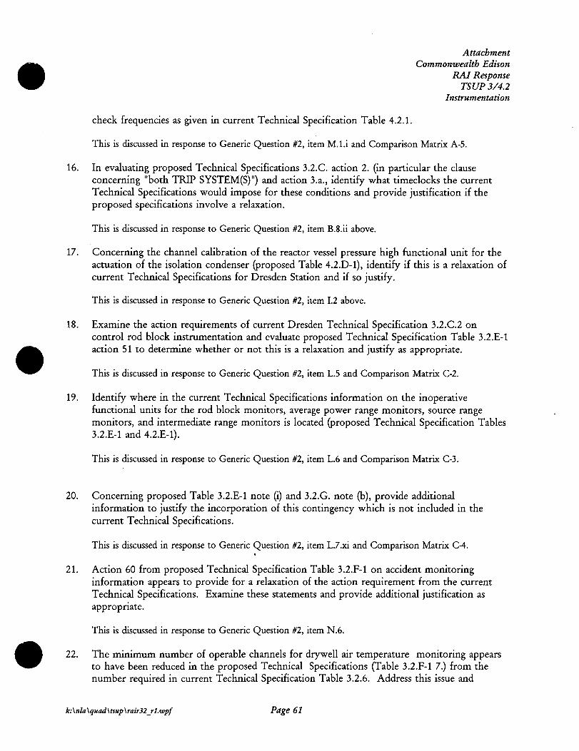
check frequencies as given in current Technical Specification Table 4.2.1.
Attachment Commonwealth Edison
RAJ Response TSUP3/4.2
Instrumentation
This is discussed in response to Generic Question #2, item M.1.i and Comparison Matrix A-5.
16. In evaluating proposed Technical Specifications 3.2.C. action 2. (in particular the clause concerning "both TRIP SYSTEM(S)") and action 3.a., identify what timeclocks the current Technical Specifications would impose for these conditions and provide justification if the proposed specifications involve a relaxation.
This is discussed in response to Generic Question #2, item B.8.ii above.
17. Concerning the channel calibration of the reactor vessel pressure high functional unit for the actuation of the isolation condenser (proposed Table 4.2.D-1), identify if this is a relaxation of current Technical Specifications for Dresden Station and if so justify.
This is discussed in response to Generic Question #2, item I.2 above.
18. Examine the action requirements of current Dresden Technical Specification 3.2.C.2 on control rod block instrumentation and evaluate proposed Technical Specification Table 3.2.E-1 action 51 to determine whether or not this is a relaxation and justify as appropriate.
This is discussed in response to Generic Question #2, item L.5 and Comparison Matrix C-2.
19. Identify where in the current Technical Specifications information on the inoperative functional units for the rod block monitors, average power range monitors, source range monitors, and intermediate range monitors is located (proposed Technical Specification Tables 3.2.E-1 and 4.2.E-1).
This is discussed in response to Generic Question #2, item L.6 and Comparison Matrix C-3.
20. Concerning proposed Table 3.2.E-1 note (i) and 3.2.G. note (b), provide additional information to justify the incorporation of this contingency which is not included in the current Technical Specifications.
This is discussed in response to Generic Question #2, item L.7.xi and Comparison Matrix C-4.
21. Action 60 from proposed Technical Specification Table 3.2.F-1 on accident monitoring information appears to provide for a relaxation of the action requirement from the current Technical Specifications. Examine these statements and provide additional justification as appropriate.
This is discussed in response to Generic Question #2, item N.6.
22. The minimum number of operable channels for drywell air temperature monitoring appears to have been reduced in the proposed Technical Specifications (Table 3.2.F-1 7.) from the number required in current Technical Specification Table 3.2.6. Address this issue and
k:\nla\quad\tsup \rair32 _rl.wpf Page 61

Attachment Commonwealth Edison
RAJ Response TSUP3/4.2
Instrumentation
provide justification as appropriate. Additionally, indicate where in the proposed Technical Specification the requirements for narrow range torus water level indication, torus pressure, and torus to drywell differential pressure (from Table 3.2.6) are captured.
This is discussed in response to Generic Question #2, item N.5 and Comparison Matrix D-1.
23. In comparing proposed Technical Specification Table 4.2.F-1 and current Technical Specification Table 4.2.4, indicate whether or not the following surveillance requirements are relaxations and if so provide justification as necessary. For example, examine channel check and channel calibration frequencies between the current TS and the proposed TS and note deviations.
Reactor Vessel Pressure Reactor Vessel Water Level Torus Water Level - Narrow Range Torus Water Level - Wide Range Drywell Pressure - Narrow Range Drywell Air Temperature Torus Water Temperature Torus Water Level - Wide Range Acoustic SRV Position Indicators Neutron Monitors
Channel Check Channel Check Channel Check
Channel Check Channel Check Channel Check
Channel Check
Channel Calib. Channel Calib. Channel Calib. Channel Calib. Channel Calib.
Channel Calib. Channel Calib. Channel Calib. Channel Calib.
This is discussed in response to Generic Question #2, items 0.2, 0.4, and Comparison Matrix D-2.
24. Indicate where in the current Technical Specifications information related to the Drywell Hydrogen Concentration - Analyzer and Monitor is located (proposed Technical Specification Table 4.2.F-1 8.).
This is discussed in response to Generic Question #2, Comparison Matrix D-1.
k:\nla\quad\tsup \rair32 _rl.wpf Page 62

Com_A_ Matrix A-1 Dresde,.:ble 3.2.1 Quad Cities Table 3.2-1 TSUP Table 3.2.A-1
TSUP Item CTS Instrument No(s). ji:~Q :n . ..-:,.z,·,t$<]"1-C'.J{#-"'1;\it' .. .&":Jhif!i·-)".1·ijtl"'"-";.-4-<·j:;. v-iM~?-"'""/· ·
Reactor Low Water Level 1.a, 2.a, 4.b
Reactor Low Low Water 3.a
High Drywall Pressure 1.b, 2.b
High Flow Main Steam Line 3.d
High Temperature Main Steamllne Tunnel 3.e
High Radiation Main Steamllne Tunnel 3.b
Low Pressure Main Steamline 3.c
High Flow Isolation Condenser Line Steamllne Side (Dresden CTS and TSUP onlyl 5.a
High Flow Isolation Condenser Condensate Return Side !Dresden CTS and TSUP onlyl 5.b
High Flow RCIC Steamllne (Quad Cities CTS and TSUP onlyl 5.a
RCIC Turbine Area High Temperature (Quad Cities CTS and TSUP onlyl 5.c
High Flow HPCI Steamline 6.a
High Temperature HPCI Steamllne Area 6.c
HPCI Steamline pressure (Quad Cities CTS only; Dresden and Quad Cities TSUP) 6.b
CTS Modes
i:~··';_,;,.~,,;,::z,;;(·r .;
1, 2, 3
1, 2, 3
1, 2. 3
1, 2, 3
1, 2, 3
1, 2, 3
1, 2. 3
1, 2, 3
1, 2, 3
1, 2, 3
1, 2, 3
1, 2, 3
1, 2, 3
1, 2, 3
ISOLATION ACTUATI TRUMENTATION • CTS Min. TSUP Min.
TSUP Channels per Channels per CTS TSUP Modes Trip System Trip System CTS Setpoint TSUP Setpoint Action Actions TSUP Functional Unit
,,'tf.'::'.;'<;;,%'"·'"'' ¥,,, ,~,~+".l!'l'? '"'-'""t":,,.'~-# ,Y;;,::"> ii:~ ''.!'.«<'"~''""f""'~""§#fl{JJ:ft"'.:'..::;•.-1 ··:.: .. .:'i<'.i" ·~:-0~i'~-i-"'~hf;o,:,_ . .:_-;;.;;;<,;,f.V:i,i;·Y .J,'!/ ~ .• '"~-~""·":'::'..~'. -~~-.. ~·,,: .. ''::<:·=>.~~&h&~'=",'i:>' 5;.'''" :;:;"':;;;~:r :.,~~':""~"·/.:tif<'1!'' '°"'''"'"<-::'.=;, ="r"::_.·,:r;.,~:1~·t-..;:ti'.~
1, 2, 3 and • 2 2 > 144" aboveTAF 2 144" above TAF A 20, 23, 24, Reactor Vessel Water Level - Low
1, 2, 3 2 2 2 84" above TAF 2 84" above TAF A 21 Reactor Vessel Water Level - Low low
S 2 pslg !DI; S 2.5 pslg S 2 pslg !DI; S2.5 1, 2, 3 2 2 101 pslg 101 A 20, 24 Drywall Pressure - High
S 120% !DI; S140% S 120% !DI; S140% 1, 2, 3 2/llne (DI; 8 101 2/line (01 (OJ B 21 MSL Flow - High
1, 2, 3 2/line IOI; 8 101 OPEN ITEM S 200° F S 200° F B 21 MSL Tunnel Temperature - High
S 3x FPB !DI; S 15x FPB s3x FPB (DI; S 15x 1, 2, 3 2 2 101 FPB 101 B 21 MSL Tunnel Radiation - High
2 850 pslg !DI; 2 825 pslg 2 2 (01 2 825 psig B 22 MSL Pressure - Low
s 300% flow rated steam S 300% flow rated 1, 2, 3 flow steam flow c 23 (Isolation Condenserl Steam Flow - High
S.32" (Unit 21; s 14.8" S 32" (Unit 21; s 14.8" 1, 2, 3 !Unit 31 !Unit 31 c 23 (Isolation Condenserl Return Flow - High
S 300% flow rated steam S 300% flow rated (Reactor Core Isolation Coollngl Steam Flow -1, 2, 3 flow steam flow c 23 High
(Reactor Core Isolation Coolingl Area 1, 2, 3 2 2 S 170° F S 170° F c 23 Temperature - High
s 300% flow rated steam S 300% flow rated (High Pressure Coolant lnjectlonl Steam Flow 1, 2, 3 flow steam flow D 23 High
S200° F (DI; s 170° F S 200° F IOI; s 170° (High Pressure Coolant lnjectionl Area 1, 2, 3 4(DI;2101 8 (01; 2 (01 (01 F (01 D 23 Temperature - High
2 100 pslg (Quad Cities 2 80 psig IOI; > 100 (High Pressure Coolant lnjectionl Reactor 1, 2, 3 2 2 CTS onlyl pslg (01 D 23 Vessel Pressure - Low

Com A Matrix A-·2 Dresde~ble 3.2.1 Quad Cities Table 3.2-1 TSUP Table 3.2.A-1
CTS CTS Instrument Action
Reactor Low Water Level A
ISOLATION ACTUATI ACTIO
TRUMENTATION
TSUP CTS TSUP Action
Hot Shutdown In 12 hours and Cold Shutdown in the next
Initiate shutdown - Cold Shutdown in 24 hours 24 hours 20
Close affected valves in 1 hour and declare system Inoperable. 23
Establish Secondary Containment with SBGT operating In 1 hour. 24
• TSUP Functional Unit
i'.''··<\.-f .. 'i-"''~~1:
Reactor Vessel Water Level - Low (Primary Containment Isolation)
Reactor Vessel Water Level - Low (Reactor Water Cleanup System Isolation; RHR Shutdown Cooling Isolation)
Reactor Vessel Water Level - Low (Secondary Containment Isolation)
• ••v"• • ~ "'·' .•• .-w.·,,.,· -'" -.....-<" • ..::., ... . ·-·J.,¥ ...,.,,~. , .·~ .. ., ~··. ~,~,, .. .,,. , . ., "' , ... ·'=''"'"<'''•· "=<'• ., '"· '"·''"·' ··'-'''"'· --'"' .. · _.,,,,,.,,,. -~ ·"·"" .. ·.·.,-. '~"~-"1'"."'~"'·::0:·~'"ij'•• ·')-""t'l "''·,.wrhr·~"ii.L1;~- ,.~----¥=·--~''···.
Startup with associated Isolation valves closed in 8 hours,
Reactor Low Low Water A Initiate shutdown - Cold Shutdown In 24 hours and Cold Shutdown in next 24 hours 21 Reactor Vessel Water Level - Low Low .• ... . .. .. .,,
·~ .. ... w•• "~'" ~;:.,. JM";, • .., ..... , . .. :···;.:....,· ...... .,., ·;oi.v...-w-~:~ii!Zi*".;w·
Hot Shutdown In 12 hours and Cold Shutdown In the next
High Drywall Pressure A lnlilate shutdown - Cold Shutdown in 24 hours 24 hours 20 Drywall Pressure - High (Primary Containment Isolation)
Establish Secondary Containment with SBGT operating in 1 hour. 24 Drywall Pressure - High (Secondary Containment Isolation)
,. •.•. ,- -~ .• .... - ... , . .. """ • .,.~ '"< ., • "" ... .. ~.- .. ... · ~ ''" .. , .. . ,. ~· ., . .,,~~; Startup with associated Isolation valves closed in EftiCn.i"is,
High Flow Main Steam Line B Initiate load reduction - Hot Standby In 8 hours and Cold Shutdown In next 24 hours 21 MSL Flow - High
High Temperature Main Steamline Startup with associated isolation valves closed in B hours,
Tunnel B Initiate load reduction - Hot Standby In B hours and Cold Shutdown In next 24 hours 21 MSL Tunnel Temperature - High
Startup with associated Isolation valves closed in 8 hours, High Radiation Main Steamilne Tunnel 8 Initiate load reduction - Hot Standby In B hours and Cold Shutdown In next 24 hours 21 MSL Tunnel Radiation - High
Low Pre.Sure Main Steamllne B Initiate load reduction - Hot Standby In 8 hours Startup within 8 hours 22 MSL Pressure • High .. ·-High Flow Isolation Condenser Line
Steamilne Side (Dresden CTS and Close affected valves In 1 hour and declare system
TSUP only) c Close applicable system Isolation valves inoperable. 23 (Isolation Condenser) Steam Flow - High
High Flow Isolation Condenser Condensate Return Side (Dresden Close affected valves In 1 hour and declare system
CTS and TSUP only) c Close applicable system Isolation valves Inoperable. 23 (Isolation Condenser) Return Flow - High
High Flow RCIC Steamllne (Quad Close affected valves in 1 hour and declare system
Cities CTS and TSUP only) c Close applicable system Isolation valves Inoperable. 23 (Reactor Core Isolation Cooling) Steam Flow - High
RCIC Turbine Area High Temperature Close affected valves In .1 hour and declare system (Quad Cities CTS. and TSUP only) c Close applicable system Isolation valves Inoperable. 23 (Reactor Core Isolation Cooling) Area Temperature - High
.. "" Close affected valves in 1 hour and declare system
High Flow HPCI Steamline D Close HPCI Isolation Valves Inoperable. 23 (High Pressure Coolant Injection) Steam Flow - High
High Temperature HPCI Steamllne Close affected valves In 1 hour and declare system Area D Close HPCI Isolation Valves Inoperable. 23 (High Pressure Coolant Injection) Area Temperature - High
HPCI Steamline pressure (Quad Cities CTS only; Dresden and Quad Cities Close affected valves In 1 hour and declare system (High Pressure Coolant lnjectionl Reactor Vessel Pressure
TSUPI D Close HPCI Isolation Valves Inoperable. 23 Low
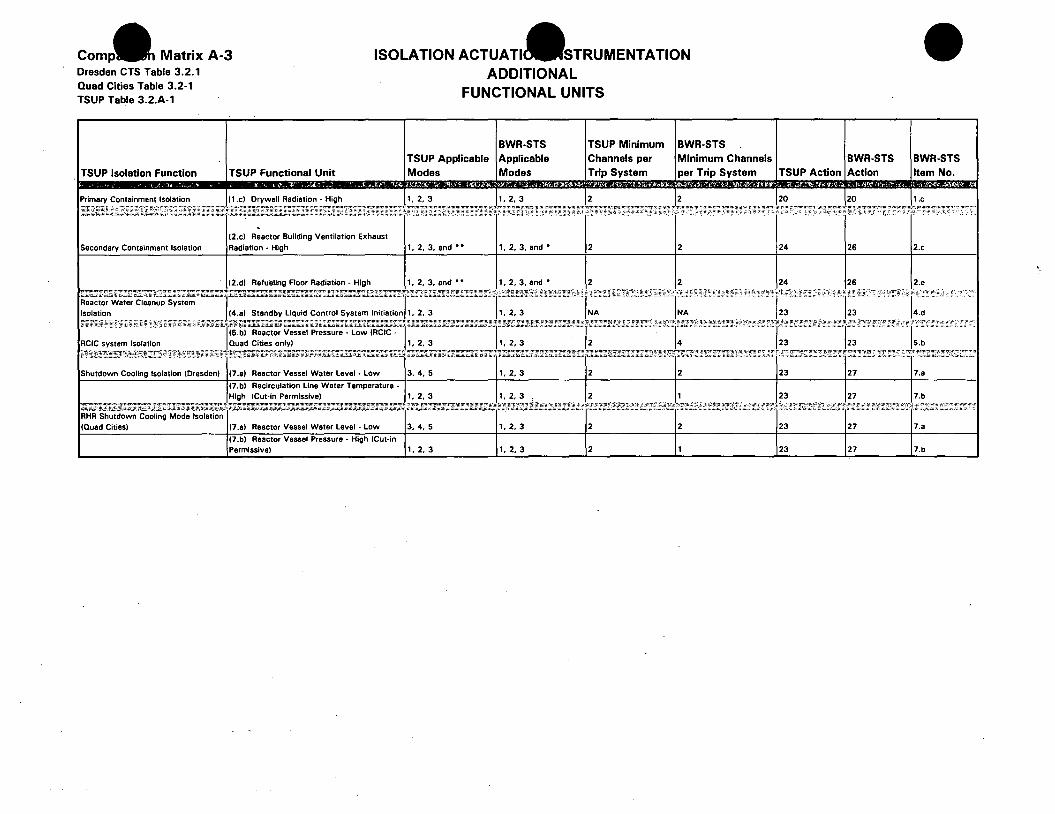
Matrix A-3 Dresden CTS Table 3.2.1
ISOLATION ACTUATI STRUMENTATION ADDITIONAL
FUNCTIONAL UNITS Quad Cities Table 3.2-1 TSUP Table 3.2.A-1
BWR-STS TSUP Minimum BWR-STS TSUP Applicable Applicable Channels per Minimum Channels
TSUP Isolation Function TSUP Functional Unit Modes Modes Trip System per Trip System
Primary Containment Isolation (1.c) Drywall Radiation - High 1, 2, 3 1, 2. 3 2 2 ,.,,,,,_
''"'"" ..... .... ·:• . .,, .......
. (2.cl Reactor Building Ventilation Exhaust
Secondary Containment Isolation Radiation - High 1, 2. 3, and • • 1, 2, 3, and • 2 2
(2.d) Refueling Floor Radiation - High 1, 2, 3, and • • 1, 2, 3, and • 2 2 ...... . ··•· .. ,., ........
Reactor Water Cleanup System Isolation I (4.a) Standby Liquid Control System Initiation 11 2, 3 1 2. 3 NA NA
..... . .. (5.b) Vessel Pressure - Low IRCIC -
RCIC system Isolation Quad Cities only) 11 2. 3 1, 2, 3 2 4 ... -·-·- ·.o,;;,;·x.;,;;·:;.h;:u.;·
Shutdown Cooling Isolation (Dresden) (7.a) Raactor Vessel Water Level - Low 3, 4, 5 1, 2. 3 2 2
(7.bl Recirculation Line Water Temperature -High (Cut-In Permissive) 1, 2, 3 1, 2. 3 2 1
.. IRHR Shutdown Cooling Mode Isolation (Quad Cities) 17.al Reactor Vessel Water Level - Low 3, 4, 5 1, 2. 3 2 2
(7.bl Reactor Vessel Pressure - High (Cut-In Permissive I 1, 2. 3 1, 2. 3 2 1
BWR-STS BWR-STS TSUP Action Action Item No.
20 20 1.c
,;:-.- . .-..... "--· -···- · ........
24 26 2.c
24 26 2.e
.................. '"····· · ..
123 23 4.d .................... :.;.".,
123 23 5.b .... . .,,, "'·.;:.;.,;:.•C-'•·C.'•,; ...
23 27 7.a
123 27 7.b
·- ... , ............... ,. ... ::.:···
23 27 7.a
23 27 7.b
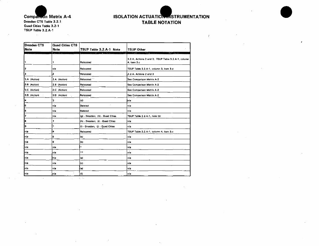
Comp- Matrix A-4 Dresden CTS Table 3.2.1 Quad Cities Table 3.2-1 TSUP Table 3.2.A-1
Dresden CTS Quad Cities CTS Note Note
1 1
2 n/a
3 2
3.A (Action) 2.A (Action)
3.B (Action) 2.B (Action)
3.C (Action) 2.C (Action)
3.D (Action) 2.D (Action)
4 3
5 n/a
6 n/a
7 n/a
8 7
9 . n/a 4
n/a 5
n/a 6
n/a n/a
n/a n/a
n/a n/a
n/a n/a
n/a n/a
n/a n/a
ISOLATION ACTUATIO STRUMENTATION TABLE NOTATION
TSUP Table 3.2.A-1 Note TSUP Other
3.2.A, Actions 2 and 3; TSUP Table 3.2.A-1, column Relocated 4, Item 3.c
Relocated TSUP Table 3.2.A-1, column 3, item 3.d
Relocated 3.2.A, Actions 2 and 3
Relocated · See Comparison Matrix A-2
Relocated See Comparison Matrix A-2
Relocated See Comparison Matrix A-2
Relocated See Comparison Matrix A·2
(di n/a
Deleted n/a
Deleted n/a
(g) - Dresden; (hi - Quad Cities TSUP Table 2.2.A·l, note (bl
(h) - Dresden; (i) • Quad Cities n/a
(I) - Dresden; Iii - Quad Cities n/a
Relocated TSUP Table 3.2.A-1, column 4, Item 3.c
(kl n/a
(b) n/a . n/a .. n/a
!al n/a
(cl n/a
(el n/a
(f) n/a
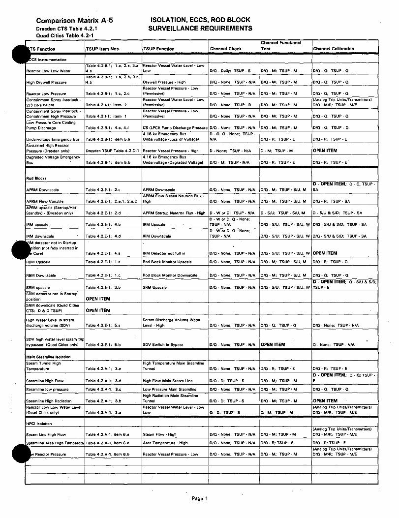
Comparison Matrix A-5 Dresden CTS Table 4.2.1 Quad Cities Table 4.2-1
TS Function TSUP Item Nos.
CS Instrumentation
Table 4.2.B·1; 1.a, 2.a, 3.a,
Reactor Low Low Water 4.a
Table 4.2.B-1; 1.b, 2.b, 3.b, High Drywall Pressure 4.b·
Reactor Low Pressure Table 4.2.B-1; 1.c, 2.c
Containment Spray Interlock -2/3 core height Table 4.2.1-1; item 2
Containment Spray Interlock -Containment High Pressure Table 4.2.1-1; item 1
Low Pressure Core Cooling
Pump Discharge Table 4.2.B-1; 4.e. 4.1
Undervoltage Emergency Bus Table 4.2.B-1; item 5.a
Sustained High Reactor Pressure (Dresden only) Dresden TSUP Table 4.2.D-1
Degraded Voltage Emergency
Bus Table 4.2.B-1; item 5.b
Rod Blocks
APRM Downscale Table 4.2.E-1; 2.c
APRM Flow Variable Table 4.2.E-1; 2.a.1, 2.a.2
APRM upscale (Startup/Hot Standby) - (Dresden only) Table 4.2.E-1; 2.d
IRM upscale Table 4.2.E-1; 4.b
IRM downscale Table 4.2.E-1; 4.d
M detector not in Startup ition (not fully inserted in Core) Table 4.2.E-1; 4.a
RBM Upscale Table 4.2.E-1; 1.a
RBM Downscale Table 4.2.E-1; 1.c
SRM upscale Table 4.2.E-1; 3.b
SRM detector not in Startup position OPEN ITEM
SRM downscale (Quad Cities CTS; D & Q TSUP) OPEN ITEM
High Water Level in scram discharge volume (SDVI Table 4.2.E-1; 5.a
SDV high water level scram trip
bypassed (Quad Cities only) Table 4.2.E-1; 5.b
Main Staamllna Isolation
Steam Tunnel High Temperature Table 4.2.A-1; 3.a
Steamline High Flow Table 4.2.A-1; 3.d
Steamline low pressure Table 4.2.A-1; 3.c
Steamline High Radiation Table 4.2.A-1; 3.b
Reactor Low Low Water Level (Quad Cities only) Table 4.2.A-1; 3.a
HPCI Isolation
Steam Line High Flow Table 4.2.A-1, item 6.a
Steamline Area High Temperatu Table 4.2.A-1. item 6.c
Reactor Pressure Table 4.2.A-1, item 6.b
ISOLATION, ECCS, ROD BLOCK SURVEILLANCE REQUIREMENTS
TSUP Function Channel Check
Reactor Vessel Water Level - Low Low D/Q ·Daily; TSUP • S
Drywall Pressure - High D/Q - None; TSUP-N/A
Reactor Vessel Pressure - Low (Permissive) D/Q - None; TSUP- N/A
Reactor Vessel Water Level - Low (Permissive) D/Q- None; TSUP- D
Reactor Vessel Pressure - Low (Permissive) D/Q - None; TSUP- N/A
CS (LPCI) Pump Discharge Pressure D/Q - None; TSUP-N/A
4. 16 kv Emergency Bus D - Q, Q - None; TSUP-Undervoltage (Loss of Voltage) N/A
Reactor Vessel Pressure - High D - None; TSUP- N/A
4. 16 kv Emergency Bus
Undervoltage (Degraded Voltage) D/Q-M; TSUP- N/A
APRM Downscale D/Q- None; TSUP- N/A
APRM Flow Biased Neutron Flux -High D/Q- None; TSUP- N/A
APRM Startup Neutron Flux - High D-WorD; TSUP- N/A
D - W or D, Q - None; IRM Upscale TSUP - N/A
D - W or D, Q - None; IRM Downscale TSUP- N/A
IRM Detector not lull in D/Q - None; TSUP- N/A
Rod Block Monitor Upscale D/Q- None; TSUP- N/A
Rod Block Monitor Downscale D/Q - None; TSUP- N/A
SRM Upscale D/Q- None; TSUP- N/A
Scram Discharge Volume Water Level - High D/Q - None; TSUP-N/A
SDV Switch in Bypass O/Q - None; TSUP-N/A
High Temperature Main Steamline
Tunnel D/Q - None; TSUP - N/A
High Flow Main Steam Line O/Q • D; TSUP - S
Low Pressure Main Steamllne D/Q- None; TSUP • N/A
High Radiation Main Steamline Tunnel O/Q - D; TSUP • S
Reactor Vessel Water Level - Low Low Q- D; TSUP- S
Steam Flow - High O/Q- None; TSUP • N/A
Area Temperature - High O/Q - None; TSUP- N/A
Reactor Vessel Pressure - Low D/Q - None; TSUP- N/A
Page 1
Channel Functional Test Channel Calibration
D/Q-M; TSUP- M D/Q-Q; TSUP- Q
D/Q-M; TSUP- M D/Q-Q; TSUP- Q
D/Q-M; TSUP- M D/Q-Q; TSUP- Q
(Analog Trip UnitsfTransmitters)
D/Q-M; TSUP-M D/Q - M/R; TSUP - M/E
D/Q-M; TSUP- M D/Q- Q; TSUP- Q
D/Q-M; TSUP- M D/Q-Q; TSUP- Q
D/Q-R; TSUP - E D/Q-R; TSUP - E
D- M; TSUP- M OPEN ITEM
D/Q - R; TSUP - E D/Q-R; TSUP - E
D - OPEN ITEM; Q- Q, TSUP-
D/Q-M; TSUP-S/U, M SA
D/Q-M; TSUP- S/U, M D/Q-R; TSUP- SA
D - S/U; TSUP - S/U, M D - S/U & SID; TSUP- SA
D/Q-S/U; TSUP- S/U. W D/Q - S/U & SID; TSUP- SA
D/Q-S/U; TSUP- SIU. W D/Q - S/U & SID; TSUP- SA
D/Q-S/U; TSUP- SIU, W OPEN ITEM
D/Q-M; TSUP-S/U, M D/Q-R; TSUP- Q
D/Q - M; TSUP - S/U, M D/Q-Q; TSUP - Q
D - OPEN ITEM; Q- S/U & SID,
O/Q - S/U; TSUP - SIU. W TSUP- E
D/Q - Q; TSUP - Q D/Q - None; TSUP - N/A
OPEN ITEM Q - None; TSUP- N/A
D/Q-R; TSUP -·E D/Q-R; TSUP- E
D • OPEN ITEM; Q- Q; TSUP-
D/Q-M; TSUP- M E
0/Q-M; TSUP' M O/Q-Q; TSUP- Q
D/Q-M; TSUP- M OPEN ITEM (Analog Trip Units/Transmitters)
Q- M; TSUP- M D/Q - MIR; TSUP - M/E
(Analog Trip Units/Transmitters)
D/Q - M; TSUP - M O/Q - M/R; TSUP • M/E
D/Q • R; TSUP - E O/Q - R; TSUP - E
(Analog Trip Units/Transmitters) O/Q - M; TSUP - M D/Q- M/R; TSUP- M/E

Comparison Matrix A-5 Dresden CTS Table 4.2.1 Quad Cities Table 4.2-1
CTS Function TSUP Item Nos.
IC Isolation (Quad Cities nlyl
High Flow RCIC Steamline Table 4.2.A· 1. item 5.a
RCIC Turbine Area High Temperature Table 4.2.A-1, item 5.c
Low Reactor Pressure Table 4.2.A-1, item 5.b
Isolation Condenser Isolation (Dresden only)
High Flow Isolation Condenser
Line Steamline Side Table 4.2.A-1, item 5.a
High Flow Isolation Condenser
Condensate Return Side Table 4.2.A-1, item 5.b
Containment Monitoring (Dresden CTS Tabla 4.2. 1 only;
D and Q TSUPI
Pressure Indicator - -5 in. Hg to OPEN ITEM (for TSUP
+5 psig Tables 3/4.2.F-11
Pressure Indicator - 5 in. to + 70in. Hg Table 4.2.F-1; item 5
Temperature Table 4.2.F-1; item 7
Drywall - Torus Differential
Pressure 4.7.H
Torus Water Level Indicator -Narrow Range DELETED
Torus Water Level - 40 in. sight glass DELETED
faty/Rallal Valve Monitoring resdan CTS Tabla 4.2.1 only;
D and Q TSUPl
Safety/Relief Valve Position TSUP Table 4.2.F-1, Item Indicator (Acoustic Monitor) 10; TSUP 4.6.F.2
Safety/Relief Valve Position TSUP Table 4.2.F-1, Item
Indicator (Temperature Monitor) 10; TSUP 4.6.F.2
Safety Valve Position Indicator TSUP Table 4.2.F-1, item (Acoustic Monitor) 10; TSUP 4.6.E.1
SafetyValve Position Indicator TSUP. Table 4.2.F-1, item (Temperature Monitor) 10; TSUP 4.6.E.1
Reactor Building Vant Isolation and SBGT Initiation
Refueling Floor Radiation
Monitors TSUP Table 4.2.A· 1, item 2.d
Steam Jet Air Ejector Off-Gu Isolation (Quad Cities CTS Table 4.2· 1 only I Relocated to ODCM
Control Room V antllatlon System Isolation (Quad Cities CTS and TSUP o.nlyl
Table 4.2.A-1; 1.a. 2.a, (4.b
Reactor Low Water Level - TSUP RWCU isolation)
Table 4.2.B-1; 1.b. 2.b, 3.b, Drywall High Pressure 4.b; Table 4.2.A-1, 1.b, 2.b
Main Steamline High Flow Table 4.2.A-1; item 3.d
Toxic Gas Analyzer TSUP 4.2.K
ISOLATION, ECCS, ROD BLOCK SURVEILLANCE REQUIREMENTS
TSUP Function Channel Check
(Reactor Core Isolation Cooling) Steam Flow - High Q - None; TSUP- N/A
(Reactor Core Isolation Cooling) Area Temperature - High Q ·None; TSUP-N/A
Reactor Vessel Pressure - low Q ·None; TSUP- N/A
(Isolation Condenser) Steam Flow • High D • None; TSUP - N/A
(Isolation Condenser) Return Flow - High D • None; TSUP - N/A
Drywall Pressure - Narrow Range 0 - None; TSUP • M
Drywall Air Temperature 0- O; TSUP- M
Drywall - Suppression Chamber Differential Pressure 0 • None; TSUP • 0
Safety/Relief Valve Position Indicators 0- M; TSUP- M
Safety/Relief Valve Position Indicators D· M; TSUP- M
Safety/Relief Valve Position Indicators 0- M; TSUP· M
Safety/Ralief Valve Position Indicators 0-M; TSUP· M
Refueling Floor Radiation - High D/Q • 0; TSUP - S
Reactor Vessel Water Level • Low Q- O; TSUP- S
Drywall Pressure - High Q- None; TSUP - NA
MSL Flow - High 0- O; TSUP- S
Toxic Gas Monitoring Q. O; TSUP- S
Page 2
Channel Functional Test Channel Calibration
Q- Q; TSUP- M Q-Q; TSUP- 0
Q- R; TSUP - E 0-R; TSUP - E
Q- Q; TSUP- M Q. Q; TSUP- Q
D- M; TSUP- M D- Q; TSUP- 0
D- M; TSUP • M D - Q; TSUP- Q
0 - None; TSUP- N/A OPEN ITEM
D ·None; TSUP- N/A 0 • R; TSUP - E
0 ·None; TSUP - None OPEN ITEM
0 • R; TSUP - None OPEN ITEM
D - None; TSUP - None 0 - 18 months; TSUP • E
0 - R; TSUP - None OPEN ITEM
0 • None; TSUP - None 0 - 18 months; TSUP - E
O/Q • M; TSUP - M D - OPEN ITEM; Q'. Q, TSUP - E
(Analog Trip Units/Transmitters) Q-M; TSUP- M O/Q • M/R; TSUP - M/E
Q-M; TSUP· M Q- Q; TSUP· Q
Q-M; TSUP- M Q • Q; TSUP- E
Q-M; TSUP· M Q - 18 months; TSUP - E

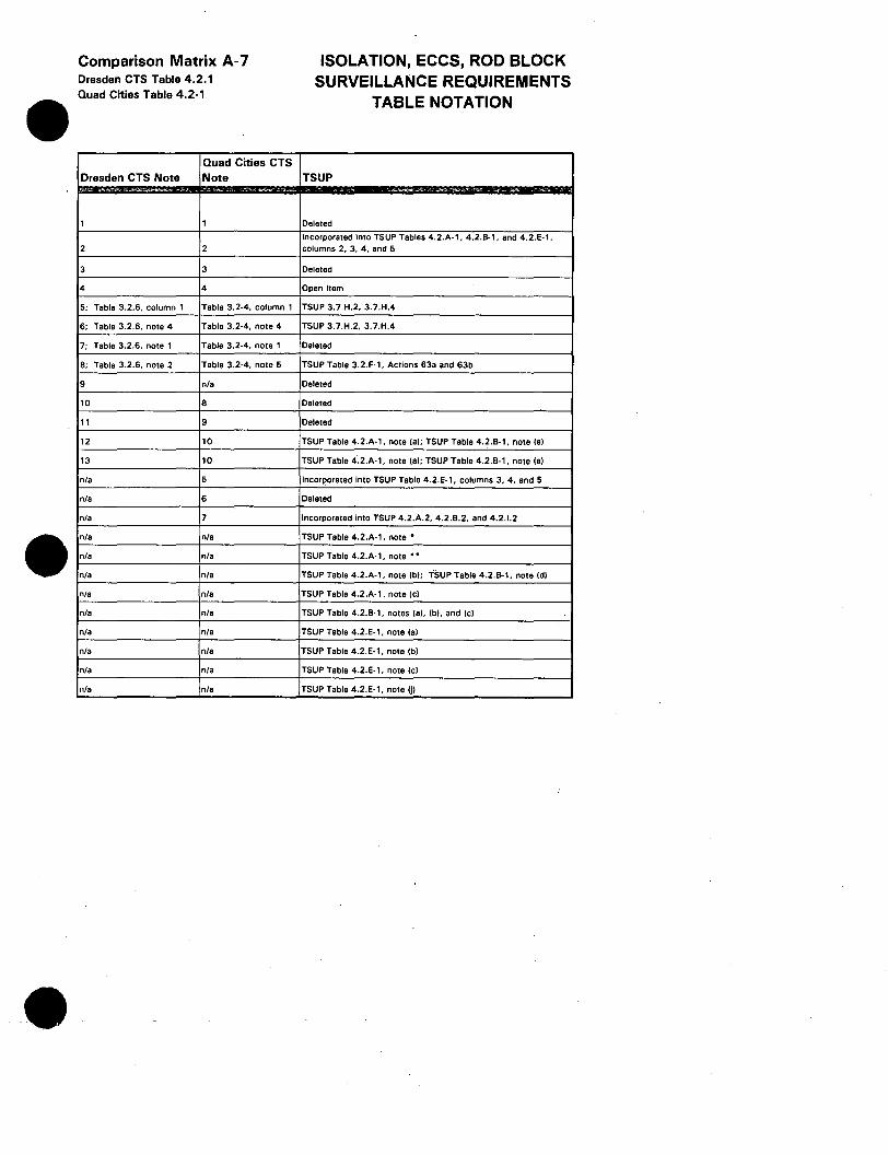
•
•
Comparison Matrix A-7 Dresden CTS Table 4.2.1 Quad Cities Table 4.2-1
Quad Cities CTS Dresden CTS Note Note
1 1
2 2
3 3
4 4
5; Table 3.2.6, column 1 Table 3.2·4, column 1
6; Table 3.2.6, note 4 Table 3.2-4, note 4
7; Table 3.2.6, note 1 Table 3.2-4, note 1
8; Table 3.2.6, note 2 Table 3.2-4, note 5
9 n/a
10 8
11 9
12 10
13 10
n/a 5
n/a 6
n/a 7
n/a n/a
n/a n/a
n/a n/a
n/a n/a
n/a n/a
nta n/a
n/a n/a
n/a n/a
n/a n/a
ISOLATION, ECCS, ROD BLOCK SURVEILLANCE REQUIREMENTS
TABLE NOTATION
TSUP
Deleted
Incorporated into TSUP Tables 4.2.A·1, 4.2.B-1, and 4.2.E·l, columns 2, 3. 4, and 5
Deleted
Open Item
TSUP 3.7.H.2, 3.7.H.4
TSUP 3.7.H.2. 3.7.H.4
Deleted
TSUP Table 3.2.F-1, Actions 63a and 63b
Deleted
Deleted
Deleted
TSUP Table 4.2.A· 1, note (aJ; TSUP Table 4.2.B-1, note (el
TSUP Table 4·.2.A· 1, note (aJ; TSUP Table 4.2.B-1, note (el
Incorporated into TSUP Table 4.2.E· 1, columns 3, 4, and 5
Deleted
Incorporated into TSUP 4.2.A.2, 4.2.B.2, and 4.2.1.2
TSUP Table 4.2.A-1, note•
TSUP Table 4.2.A-1, note • •
TSUP Table 4.2.A-1, note (bl; TSUP Table 4.2.B-1, note (dJ
TSUP Table 4.2.A-1, note (cl
TSUP Table 4.2.B-1. notes (aJ. (bl. and (cl
TSUP Table 4.2.E-1, note (al
TSUP Table 4.2.E· 1, note (bl
TSUP Table 4.2.E-1. note (cl
TSUP Table 4.2.E-1, note (j)

Comp Matrix C-1 Dresden Table 3.2.3 Quad Cities Table 3.2-3 TSUP Table 3.2.E-1
TSUP CTS Instrument Item
Rod Block Monitor upscale (flow bias) • Dual Loop Operation 1.a
Rod Block Monitor upscale (flow bias) • Single Loop Operation 1.a
Rod Block Monitor downscale 1.c
APRM upscale (flow bias) (Quad Cities) 2.a.1, 2.a.2
APRM upscale (flow bias) Dual Loop Operation (Dresden) 2.a.1
APRM upscale (flow blasJ Single Loop Operation (Dresden) 2.a.2
APRM Downscale 2.c
APRM upscale (Refuel and Startup/Hot Standby Model 2.d
SRM detector not In Startup position OPEN ITEM
SRM upscale 3.b
SRM downscale (Quad Cities) OPEN ITEM
IRM detector not In Startup position 4.a
IRM upscale 4.b
IRM downscale 4.d
High Water Level In scram discha.rge volume (SDVJ 5.a
SDV high water level scram trip bypassed (Q - CTS, D/Q • TSUPJ 5.b
CTS TSUP CTS Min. Applicability Appl. Channels
1, 2, & .2. 30% power 1 2
1, 2, & .2. 30% power 1 2
1 1 2
1 1 4
1 1 4
1 1 4
1 1 4
2, 5 2, 5 4
2 2, 5 4
2 (Dresden) 2, 5 (Quad Cities) 2, 5 6
2 2, 5 6
2 2, 5 6
1 •. 2 1, 2, 5 1 per bank
OPEN 1, 2 ITEM 1
Rod Block I entation
TSUP Min. Channels CTS Trip Level Setting TSUP Trip Setpoint TSUP Functional Unit
.,
2 See Core Operating Limits Report As specified in the COLR Rod Block Monitor Upscale
2 See Core Operating Limits Report As specified in the COLR Rod Block Monitor Upscale
.2. 5/125 of full scale !Dresden); ~3/125 .2. 5/125 of full scale (Dresden); .2. 3/125 2 of full scale (Quad Cities) of full scale (Quad Cities) Rod Block Monitor Downscale
APRM Flow Biased Neutron Flux - High Dual 4 S (0.58W0 + 501 • (FRP/MFLPDJ S (0.58W+ 50) Recirculation Loop Operation
APRM Flow Biased Neutron Flux - High Dual 4 S (0.58W0 + 50) I FDLRC S (0.58W+ 50) Recirculation Loop Operation
APRM Flow Biased Neutron Flux - High Single 4 S (0.58W0 + 46.5) I FDLRC S (0.58W + 46.5) Recirculation Loop Operation
4 .2. 3/125 of full scale .2. 3/125 of full scale APRM Downscale
4 S 12/125 of full scale s 12/125 of full scale APRM Startup Neutron Flux - High
3 ·Mode 2; 2 -Mode 5 s 105 counts/sec. s 1 x 1 o• counts/sec SRM Upscale
NA (Dresden); .2. 2 feet below core 6 centerline (Quad Cities) NA IRM Detector not full In
6 S 10B/125 of full scale s 108/125 of full scale IRM Upscale
.2. 5/125 of full scale (Dresden); .2. 3/125 .2. 5/125 of full scale (Dresden); .2. 3/125 6 of full scale (Quad Cities) of full scale (Quad Cities) IRM Downscale
(LT/El 26 inches above the bottom of the Instrument volume (Dresden); S25
1 per bank gallons (per bank) (Quad Cities) < 25 gallons Scram Discharge Volume Water Level - High
1 NA NA SDV Switch in Bypass
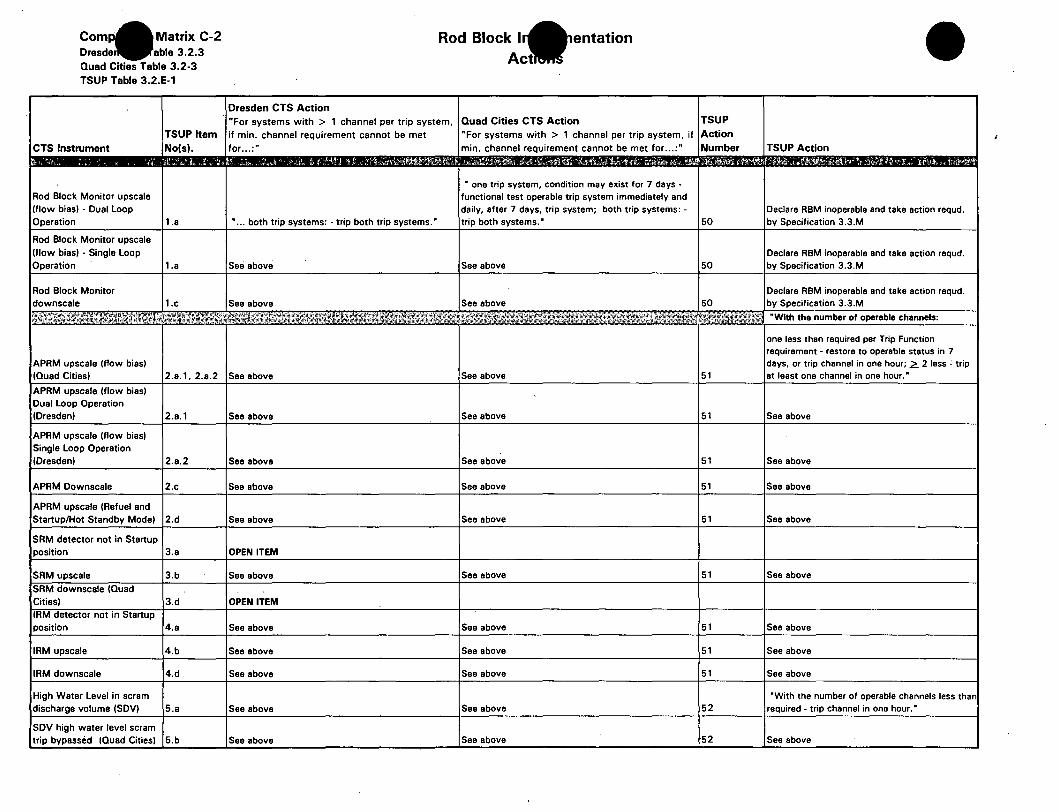
Com Matrix C-2 Dresde able 3.2.3
Quad Cities Table 3.2-3
TSUP Table 3.2.E-1
Rod Block I entation
Dresden CTS Action "For systems with > 1 channel per trip system, Quad Cities CTS Action TSUP
TSUP Item if min. channel requirement cannot be met
CTS Instrument No(s). for ... :"
Rod Block Monitor upscale (flow bias) - Dual Loop Operation 1.a
Rod Block Monitor upscale (flow bias) - Single Loop Operation 1.a
Rod Block Monitor downscale 1.c
APRM upscale (flow bias) (Quad Cities) 2.a.1, 2.a.2
APRM upscale (flow bias) Dual Loop Operation (Dresden) 2.a.1
APRM upscale (flow bias) Single Loop Operation (Dresden) 2.a.2
APRM Downscale 2.c
APRM upscale (Refuel and Startup/Hot Standby Mode) 2.d
SRM detector not in Startup position 3.a
SRM upscale 3.b
SRM downscale (Quad Cities) 3.d IRM detector not in Startup position 4.a
IRM upscale 4.b
IRM downscale 4.d
High Water Level in scram discharge volume (SDVJ 5.a
SDV high water level scram trip bypassed (Quad Cities) 5.b
• ... both trip systems: - trip both trip systems.•
See above
See above
See above
See above
See above
See above
See above
OPEN ITEM
See above
OPEN ITEM
See above
See above
See above
See above
See above
"For systems with > 1 channel per trip system, if Action min. channel requirement cannot be met for ... :"
• one trip system, condition may exist for 7 days -functional test operable trip system immediately and daily, after 7 days, trip system; both trip systems: -
Number
trip both systems.• 50
See above 50
See above 50
See above 51
See above 51
See above 51
See above 51
See above 51
See above 51
See above 51
See above 51
See above 51
See above 52
See above 52
TSUP Action
Declare RBM inoperable and take action requd. by Specification 3.3.M
Declare RBM inoperable and take action requd. by Specification 3.3.M
Declare RBM inoperable and take action requd. by Specification 3.3.M
"With the number of operable channels:
one less than required per Trip Function requirement - restore to operable status in 7 days, or trip channel in one hour; 2. 2 less ' trip at least one channel in one hour.•
See above
See above
See above
See above
See above
See above
See above
See above
"With the number of operable channels less than required - trip channel in one hour.·
See above

Comp Matrix C-3 Dresden CTS Table 3.2.3 Quad Cities Table 3.2-3 TSUP Table 3.2.E-1
TSUP TSUP Control Rod Applicable Block Function Modes
SRM Inoperative 2, 5
SRM Downscale (Dresden TSUPI OPEN ITEM
IRM Inoperative 2. 5
SDV Switch In Bypass (Dresden TSUPI OPEN ITEM
1. 2. 5 (2, 30% APRM Inoperative Power)
BWR-STS Applicable Modes
2, 5
2, 5
(1, 21, and 5
1, 2, 5
Rod Block In entation Additional Functional Units
TSUP Min. Channels BWR-STS Min. Channels per Trip Function per Trip Function TSUP Action
3 ·Mode 2 2 ·Mode 5 3 ·Mode 2 2-Mode5 51
6 6 51
1 121 52
4 4 51
BWR-STS BWR-STS Item No. Action Table 3.3.6-1, Item#
"
61 3.c
61 4.c
62 5.b
61 2.b

Comparison Matrix C-4 Dresden CTS Table 3.2.3 Quad Cities Table 3.2-3 TSUP Table 3.2.E-1
Dresden CTS Quad Cities CTS Note Note
1 1
2 2
3 3
4 4
5 5
6 6
7 7
n/a 8
n/a 9
n/a 10
n/a n/a
n/a n/a
n/a n/a
n/a n/a
n/a n/a
n/a n/a
Rod Block Instrumentation Table Notation
TSUP Table 3.2.E-1 Note TSUP Other
TSUP Tabla 3.2.E· 1. Columns 3 and 4; Actions 51 !al and 52;
(hi n/a
tel TSUP Table 4.2.E-1, note Iii
(bl - OPEN ITEM TSUP Table 4.2.E·1. note (fl· OPEN ITEM
Relocated TSUP Table 3.2.E· 1, Column 3
(cl TSUP Table 4.2.E·l, note lgl
Relocated TSUP 3.12.A
Relocated TSUP Table 3.2.E· 1, Column 3
Deleted n/a
Relocated TSUP Table 3.2.E·l, Column 2
(di • OPEN ITEM TSUP Teble 4.2.E·1, note (hi - OPEN ITEM
(fl TSUP Table 4.2.E·l, note (d)
(g) TSUP Table 4.2.E·l, note (e)
(h) n/a
Ill-OPEN ITEM n/e - OPEN ITEM
(j) TSUP Table 4.2.E·l, note (k)

Comp Matrix 0-1 Dresden able 3.2.6 Quad Cities Table 3.2-4 TSUP Table 3.2.F-1
Reactor Pressure
Reactor Water Level
Torus Water Temperature
Torus Air Temperature (Quad Cities
CTS and TSUP only)
Torus Water Level Indicator - Narrow
Range
Torus Water Level Indicator - Wide Range
Torus Water Level - Local Sight Glass
Torus Pressure
Drywall Pressure ( -5 In. Hg to + 5 pslg)
Drywall Pressure ( -10 in. Hg to + 70 In. pslg)
Drywall Pressure ( O to 250 psig)
Drywall Temperature
Neutron Monitoring
Torus to Drywall Dllferentlal Pressure
Drywall Radiation Monitor
Main Steam RV Position Acoustic Monitor
Main Steam RV Position Temperature Monitor
Main Steam SV Position Acoustic Monitor
Main Steam SV Position Temperature Monitor
Drywall Hydrogen Concentration
n/a - New Requirement
2
4
13
DELETED
3
DELETED
OPEN ITEM
6
6
5
7
11
Relocated to TSUP 3.7.H
12
10
10
10
10
9
8
1, 2
1, 2
1, 2
1, 2
1, 2
1,2
1, 2
1, 2
1, 2
1, 2
1, 2
1. 2
1, 2
1, 2
. 1. 2
1, 2
1, 2
n/a
Post Accident Moni Instrumentation
TSUP Applicable CTS Minimum TSUP Minimum CTS Channels -
Modes Channels Channels No. Provided
1, 2 D-4; 0-3
1, 2 2
1, 2 2
1, 2 2
2 Total (Narrow and 1, 2 Wide Rangel 2
2 Total (Narrow and 1,2 Wide Rangel 1 Total (Narrow Rangel
2 Total (Narrow and 1, 2 Wide Range) 1 Total (Narrow Range)
2 Total (Narrow and 1, 2 Wide Range) 2
1, 2 2 6
1, 2 2 2 4
1, with Rx Power > 16% D-1; 0- 2 2
1, 2. 3 D-1; 0-2 2
1. 2 1/valve 1/valve (Acoustic or Temp.) 1/valve
1, 2 1/valve 1/valve (Acoustic or Temp.) 1/valve
1, 2 1/valve 1/valve (Acoustic or Temp.) 1/valve
1, 2 1/valve 1/valve (Acoustic or Temp.I 1/valve
1. 2 2
1,2 n/a n/a
TSUP Required Channels
2
2
2
2
2
2 Total (Narrow Rangel
2 Total (Narrow Rangel
2
2
2
2/valve ( 1 each - Acoustic &
Temp.I
2/valve ( 1 each - Acoustic & Temp.I
2/valve ( 1 each - Acoustic & Temp.)
2/valve (1 each - Acoustic & Temp.I
2
2
Reactor Vessel Pressure
Reactor Vessel Water Level
Torus Water Temperature
Torus Air Temperatue
Torus Water Level - Wide Range
Drywall Pressure - Narrow Range
Drywall Pressure - Narrow· Range
Drywall Pressure - Wide Range
Drywall Air Temperature
!Source Range) Neutron Monitors
Drywall - Suppression Chamber Differential Pressure
Drywall Radiation Monitors
Safety/Relief Valve Position Indicators -Acoustic and Temperature
Safety/Relief Valve Position Indicators -Acoustic and Temperature
Safety/Relief Valve Position Indicators -Acoustic and Temperature
Safety/Relief Valve Position Indicators -Acoustic and Temperature
Drywall Hydrogen Concentration Analyzer and Monitor
Drywall Oxygen Concentration Analyzer
and Monitor

Com Matrix 0-2 Dresden able 4.2.6 Quad Cities Table 4.2-4 TSUP Table 4.2.F-1
CTS Instrument
Reactor Pressure
Reactor Water Level
Torus Water Temperature
Torus Air Temperature (Quad Cities CTS and TSUP only)
Torus Water Level Indicator - Narrow Range·
Torus Water Level Indicator - Wide Range
Torus Water Level - Local Sight Gla.ss.
Torus Pressure
Drywall Pressure ( -5 in. Hg to + 5 in. psig)
Drywall Pressure ( -10 in. Hg to +70 pslg)
Drywell Pressure ( 0 to 250 psig)
Drywell Temperature
Neutron Monitoring
Torus to Drywall Differential Pressure
Drywall Radiation Monitor
Main Steam RV Position Acoustic Monitor
Main Steam RV Position Temperature Monitor
Main Steam SV Position Acoustic Monitor
Main Steam SV Position Temperature Monitor
Drywall Hydrogen Concentration
n/a - New Requirement
TSUP Table 4.2.F-1
Item Nos.
1
2
4
13
DELETED
3
DELETED
OPEN ITEM
6
6
5
7
11
Relocated to TSUP 4.7.H
12
10
10
10
10
9
8
Post Accident Moni Surveillance
Instrumentation
TSUP Function Channel Check Channel Calibration
Reactor Vessel Pressure D/0-D; TSUP- M D - OPEN ITEM; 0 - 3 mos .• TSUP - E
Reactor Vessel Water Level D/0- D; TSUP- M D - OPEN ITEM; Q - 3 mos., TSUP - E
Torus Water Temperature D/Q-D; TSUP- M D - OPEN ITEM; a - 3 mos., TSUP - E
Torus Air Temperatue Q- D; TSUP-M Q-3 mos.; TSUP- E
Torus Water Level - Wide Range D/Q - M; TSUP - M D - OPEN ITEM; O - 18 mos.; TSUP - E
Drywall Pressure - Narrow Range D - OPEN ITEM; Q - 3 mos.; TSUP - E
Drywall Pressure - Narrow Range D/Q - D; TSUP - M 0 - OPEN ITEM; O - 3 mos.; TSUP - E
Drywall Pressure - Wide Range D - D, Q - M; TSUP - M D - OPEN ITEM; a - 3 mos.; TSUP - E
Drywell Air Temperature D/0-D; TSUP- M D - R, a - 3 mos.; TSUP - E
(Source Range) Neutron Monitors D/0-D; TSUP- M D - OPEN ITEM; O - 3 mos.; TSUP - E
Drywall - Suppression Chamber Differential Pressure D - D, 0 - None; TSUP - D D - OPEN ITEM; 0- 6 mos.; TSUP - E
Drywall Radiation Monitors D/0 - M; TSUP - M D - R, 0 - 18 mos.; TSUP - E
Safety/Relief Valve Position Indicators - Acoustic and Temperature D/0 - M; TSUP - M D - OPEN ITEM; Q - None; TSUP - E
Safety/Relief Valve Position Indicators • Acoustic and Temperature D/0 - M; TSUP - M D - R, 0 - 18 mos.; TSUP - E
Safety/Relief Valve Position Indicators - Acoustic and Temperature D/0 - M; TSUP - M D - OPEN ITEM; Q - None; TSUP - E
Safety/Relief Valve Position Indicators - Acoustic and Temperature D/0-M; TSUP- M D - R, 0 - 18 mos.; TSUP - E
Drywall Hydrogen Concentration Analyzer and Monitor D/Q-M; TSUP-M D/O - 3 mos.; TSUP - 0
Drywall Oxygen Concentration Analyzer and Monitor TSUP- M TSUP- E
•
•
•
ENCLOSURE 1
Evaluation of Significant Hazards Consideration TSUP3/4.2
Instrumentation
Commonwealth Edison has evaluated the proposed amendment and determined that it involves no significant hazards consideration. According to 10 CFR 50.92(c), a proposed amendment to an operating license involves no significant hazards consideration if operation of the facility, in accordance with the proposed amendment, would not:
1) Involve a significant increase in the probability or consequences of an accident previously evaluated; or
2) Create the possibility of a new or different kind of accident from any accident previously evaluated; or
3) Involve a significant reduction in a margin of safety.
1) The proposed changes do not involve a significant increase in the probability or consequences of an accident previously evaluated because:
In general, the proposed amendment represents the conversion of current requirements to a more generic format, or the addition of requirements which are based on the current safety analysis. Implementation of the5e changes will provide increased reliability of equipment assumed to operate in the current safety analysis, or provide continued assurance that specified parameters remain within their acceptance limits, and as such, will not significantly increase the probability or consequences of a previously evaluated accident.
Some of the proposed changes to the current Technical Specifications (CTS) represent minor curtailments of the current requirements which are based on generic guidance or previously approved provisions for other stations. The proposed amendment for Dresden and Quad Cities Station's Technical Specification Section 3/4.2 are based on BWR-STS (NUREG-0123, Revision 4 "Standard Technical Specifications General Electric Plants BWR/4) guidance or NRC accepted changes at later operating BWR plants. Any deviations from BWR-STS and CTS requirements do not significantly increase the probability or consequences of any previously evaluated accident for Dresden and Quad Cities Station. These proposed changes are consistent with the current safety analyses and have been previously determined to represent sufficient requirements for the assurance and reliability of equipment assumed to operate in the safety analysis, or provide continued assurance that specified parameters remain within their acceptance limits. As such, these changes will not significantly increase the probability or consequences of a previously evaluated accident;
The associated systems that make up the Instrumentation Systems are not assumed in any safety analysis to initiate any accident sequence for both Dresden and Quad Cities Stations; therefore, the probability of any accident previously evaluated is not increased by the proposed amendment. In addition, the proposed surveillance requirements for the proposed amendments to these systems are generally more prescriptive than the current requirements specified within the Technical Specifications. These more prescriptive surveillance requirements increase the probability that the

•
ENCLOSURE 1
Evaluation of Significant Hazards Consideration TSUP3/4.2
Instrumentation
Instrumentation Systems will perform their intended functions. Therefore, the proposed TS will improve the reliability and availability of all affected systems and reduce the consequences of any accident previously evaluated.
2. Create the possibility of a new or different kind of accident from any previously evaluated because:
In general, the proposed amendment represents the conversion of current requirements to a more generic format, or the addition of requirements which are based on the current safety analysis. Others represent minor curtailments of the current requirements which are based on generic guidance or previously approved provisions for other stations. These changes do not involve revisions to the design of the station, other than technically valid trip setpoint changes. Some of the changes may involve revision in the operation of the station; however, these changes provide additional restrictions which are in accordance with the current safety analyses, or are to provide for additional testing or surveillances which will not introduce new failure mechanisms beyond those already considered in the current safety analyses. Therefore, these changes will not create the possibility of a new or different kind of accident from any accident previously evaluated.
The proposed amendment for Dresden and Quad Cities Station's Technical Specification Section 3/4.2 is based on BWR-STS guidelines or NRC accepted changes at later operating BWR plants. The proposed amendment has been reviewed for acceptability at the Dresden and Quad Cities Nuclear Power Stations considering similarity of system or component design versus the BWR-STS or later operating BWRs. Any deviations from BWR-STS or CTS requirements do not create the possibility of a new or different kind of accident than previously evaluated for Dresden and Quad Cities Stations. No new modes of operation are introduced by the proposed changes. Various surveillance requirements are changed to reflect improvements in technique, frequency of performance or operating experience at later plants. Proposed changes to action statements in many places add requirements that are not in the present technical specifications or adopt requirements that have been used at other operating BWRs with designs similar to Dresden and Quad Cities. The proposed changes maintain at least the present level of operability. Therefore, the proposed changes do not create the possibility of a new or different kind of accident from any previously evaluated.
The associated systems that make up the Instrumentation Systems are not assumed in any safety analysis to initiate any accident sequence for Dresden or Quad Cities Stations. In addition, the proposed surveillance requirements for affected systems associated with the Instrumentation Systems are generally more prescriptive than the current requirements specified within the Technical Specifications; therefore, the proposed changes do not create the possibility of a new or different kind of accident from any previously evaluated .

•
ENCLOSURE 1
Evaluation of Significant Hazards Consideration TSUP3/4.2
Instrumentation
3. Involve a significant reduction in the margin of safety because:
In general, the proposed amendment represents the conversion of current requirements to a more generic format, or the addition of requirements which are based on the current safety analysis. Others represent minor cunailments of the current requirements which are based on generic guidance or previously approved provisions for other stations. Some of the later individual items may introduce minor reductions in the margin of safety when compared to the current requirements. However, other individual changes are the adoption of new requirements which will provide significant enhancement of the reliability of the equipment assumed to operate in the safety analysis, or provide enhanced assurance that specified parameters remain within their acceptance limits. These enhancements compensate for the individual minor reductions, such that taken together, the proposed changes will not significantly reduce the margin of safety.
The proposed amendment to Technical Specification Section 3/4.2 implements present requirements in accordance with the guidelines set forth in the BWR-STS. Any deviations from BWR-STS and CTS requirements do not significantly reduce the margin of safety for Dresden and Quad Cities Stations. The proposed changes are intended to improve readability, usability, and the understanding of technical specification requirements while maintaining acceptable levels of safe operation. The proposed changes have been evaluated and found to be acceptable for use at Dresden and Quad Cities based on system design, safety analysis requirements and operational performance. Since the proposed changes are based on NRC accepted provisions at other operating plants that are applicable at Dresden and Quad Cities and maintain necessary levels of system or component readability, the proposed changes do not involve a significant reduction in the margin of safety.
The proposed amendment for Dresden and Qlli'd Cities Stations will not reduce the availability of systems associated with the Instrumentation Systems when required to mitigate accident conditions; therefore, the proposed changes do not involve a significant reduction in the margin of safety.

Enclosure 2
"Information Only" Marked-up Technical Specification Pages
Section 3/4.2
Dresden Unit 2 - DPR-19 Quad Cities Unit 1 - DPR-29
BWR~STS (NUREG 0123, Draft Rev. 4}
k: \nla \quad\tsup \raicov 32. wpf
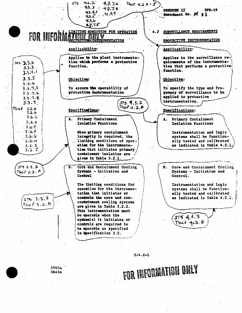
r:T~ I 3.~., . \ ! J.';;'1•l \
J. 3.5 _,\ ~.;.Co ;.~.;.s i 3 ·'? ,7,"" 3:;;1.'6
3 ·'. 'i . j I
T$1.\~ 1.a.Pr I !
\
3.a.~ 3 .o.. (, 3,a.o 3 ••• € 3 ·d.·. f ~.a.Cs ~.a.~ . , 'd.. J:.. 31). !
' '
,.--, .$~ 3,-?,,'3 ( l~v.P ~.;.;i..~ I
I
•
3960a 3843A
·ST$
...... --4 ••
ippHcability:
.Applies bl the.plant instrumentati~n whi~ performs a protective function. · ·
Obi act.he:
To assure lfm operabllitJ of protecti,,. iastz: Wll8ntation
Spec i ficatlilons;
A. Primazy:coatainment -Isolation hnctions
Whenpt"imary containment int8g!r'itJ i~ required, the limitlDg conditions of oper-
. atU. for the inatrumenta-. Um that initiates primarJ colltainmeat isolation are , givm in tab!e 3~2.1. /.
Cora and Containment Cooling Systems - Initiation and Contnl.
The limiting conditions for operation for the instrumentatian that initiates or contmriis tlae core and concontaoiinmeat cooling systems are given in Table 3.2.2.
\' I i I I
I
i i ,. I
I I I I
i I
.·This instrainentation 1111st be operable when the sywtem(s) it initiates or controls are required to
i
1 be operable as specified
i in Specification 3. S. ··-...._----·---:----·-'·
I i
/
3/4.2-1
DDSJ>D1 Ir · · Dn-19 · .. 'AllendzDent Ho· Jd a· a
l,>:,:._"o'I;;/
. -· P19TECTIVE INSTRUMENTATION
Applicabi 1i ty:
Applies to the surveillance re-1 qail"81Unta of the instrmunta- \ tioa that performs a protectivei
·function. I Obiective:
to'· seecifi the tJPe and freqaencf of surveillance applied to protective instrumentation.
Specifications:
A. Primary Containment Isolation Functions
Instrumentation and logic\\ systems shall be function- \ · ally tested and calibrated as indicated in Table 4.2.1 •
----"-----------··---· ... Core -and Containment Cooling. · Systems - Initiation and Control.
Instrumentat.ion and logic systems shall be function- 1 &lly tested and calibrated 1·1
as indicated in Table 4.2.l. !
.sr~ ~.-3.-; Tbc..(f ;.~. e
I
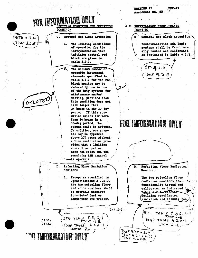
(CONT'D)
DUSDIH II . DPR-19 AmencbPDt Ho •. ~. 83 ·
4.2 mttt.ANCE REOUIREMEN'l'S (CONT'D) ·
\ .
~·~:o:n:.tro~l-. -Rod--8lo-ck--Ac-t_u_a_t7i-on-1 ~----~ c. control Ro~ Block Actu~tion'\
·----,(·---
I
\ \
3960a 3843A
( .
1. tile limitigg conditions of operat. ion for: the · . luti;m.atatlon that ·1 . .· initiates control rod block an given in Table 3.2.3.
Instrumentation &lid logic systems shall be function- · allJ tasted and calibrated as indicated in Table 4.2;.l. {
.__ __ __,,---~----~.--~~~--...\
51'!> 4· 3. lo •
. iS"4t' ~I ':i)' 6 the mlmmm 1l1111ber: 0 operable iutr:mnent· chumeb qecified in· Table 3.2.3 for: the rod . \ "block -itor 11&J be . . \\. ... ,) ... r:educed·bf one ia one I..)'-"
. of· the trip syst_. for . .alateaace uu!lft-testing. provided that this cOllditlon does not last langer than 24 hours in any .30-day period. If this con-dition ezists· for more than 2• bOU1'S lD a 30-daJ period, the systea shall be tripped. IJI addition,· one channei maJ lie bypus'ed above 307. power without a time restriction prowided tbat & limiting control l'od pattern does not exist and the remaining IBM channel
'...._-:--b operable. - . - . . / _--,......--·· -·-·· ... -···-·-
0. Refueling n..ior hdiation !!onitors
1. ·.
Except u specified in Specifications 3.2.D.2, tile tw refueling floor radiatio~monitors shall be operable whenever irradiated fuel or components are present
. i i /
I
I I
~OR INFORMATION ONLY· ;
\_r ____ _ __ "'"?"" _______ --~
o: Refueling Floor Radiation! !!onitors \
i . '
The two refueling floor ! radiation monitors shall be , i
functionally tested and ' calibrated as indicated ~-·' · .. ·· Ta Reac o , , .· uilding ventilation : . ,
L _ is=n-:~;;;~·-~·:_J) ((
ST'.; r,qe, le 'i. 3. Q.. 1- I '. ~il'M ~-e .1
\ ~£.\ P lit f,I e 4-. ~. A - I / I \ ·~:re""" ~. ot.. --~· --L~ .. r <t.7, f', t../ .b. I) \ /
\<. p 4 'l. p' 11. b • .:2) J . . I .... 1,.4.p l.f, ..,, D.d- _/

•
,.
DPR-19 DRESDEN u·· Amendment No.
FOR INfORMAJIOf~ ONLY . J2, f.i " .
2.
3.
ColiDITION IOR OPERATION
.. in the fue1 storage pool and during t"efueling or fuel movememt operations.
One of the t1ID refueling floor radiation monitors ID&J' be inoperable for 24 !lours. · If the inoperable monitor is not restored to service in this time, the reactor fluilding ventilatia.·system shall be imlated and the standbJ pa treat~ ment operated until repairs are complete.
The trip setting for the r~fueli11g floor radiation mmitors shall be set at a less I than or ecpa __ 1_t_o _____ j' lOOmr/hr. ------------..JI
,. Upon loss both re-fueling floar radiation monitors while in use, the reactor building 1 ventilatioa system I shall be isolated and . J
. the standbJ gas treat:____} · ment operated-""_------
i • I
4.2 ·SURVEILLANCE REQUIREMENTS (CONT'D) .
. __ .. ..,.---·--·~ . ... treatment system initiation l
shall be performed at least '. • 1 I each operating eye e.
S°T!> Tl'\~U: 3, 3 ~ · co 1 • ; J ~re M ~- (3 ·
n .... p TA'31e ~.d.tt-1 . c or, « J --rre "' ~ , ~
,,__-..... -----------· ------·--·~--
3960a 3843A
E. Post Accident Instrumentatioa·
The limiting C81lditions "\. for operation far the instrumentatioa, which is read out in the con-trol room, req.Sred for post accident -it:oring · are given in Table 3.2.6.
:5~ 3,?;,,{.(
'~"'" 3.~' f
3/4.2-3
··. E. Post Accident
Instrumentation
Post accide-nt instrumen- .·.__"\ tation shall be function~ 1
\
ally tested and calibrated as indicated in Table 4.2.4.
·· .. --·---~
fOR INFORMATION ONLY
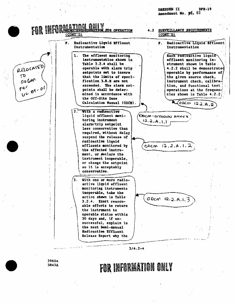
DRESDEN II DPR-19 Amendment No. '4• 83 ·
4.2 SURVEILLAHCE REQUIREMENTS (CONT'D) ·
-------·--··-;: .· Radioactive Li-1J11~id-·lf_f_l-ue_n_t-------,-.-R-a-d-:i-o.~a-c_t..,...i v-e-l:rqufd-~;
~.
!
f Cl-r l: 011 i 0•, I I
Lf V I
!
3960a 3843A
Instrumentation Instrumentation ·
1. The effluent monitoring instrumentation 1bown in Table 3; 2. 4 shall be . operable vitb alarm t.rip setpoints nt to insure that the limits of specification 3.1.B are not exceeded. ne alarm set-points. shall be determined in accordance with the Off-Site Dose Calculation Manual (ODCM).
Bae ra oactive liqui effluent monitoring instrument shown in Table . 4.2.2 shall be demonstrate I operable by performance of
1
,
the given source check, instrument check, calibra; t.ion, and functional test : · 1 operations at the frequen~ . cies shown in Table 4. 2. 2; . "'----:::-:--::====-:::=:· =--.j '
--------) 2. a radioa~tive ~~~.:..--~~--~--....
liquid effluent JDDnitoring instrument alarm/trip setpoint less conservative than r~uired, without delay suspend the release of rad.ioactive liquid effluents monitored by \ the affected instru-
\ ment, or ~ciare _the. instrument inoperable,
\\
or change the setpoint so it is acceptably cons ervat-i we.
rwith one or more radio-active liquid effluent monitoring·instruments inoperable, take the action shown in Table 3.2.4 .. Exert reasonable effol'ts to return the instrument to operable status within 30 days and, if unsuccessful, explain in the next Semi-Annual Radioacti'le Effluent Release Report vby the
OD~"' -oresoaJ Ar-J w € '< 1a.~.A.l.\ j
()CU~ l ~ I J ' A ' I • :J.. "
------------:-.. _-____..;.---------··-·----·- - .
··-·--· --·--· --·-- - ----3/4.2-4
FOR INFORMATION ONlY

3.2 LIMITING CONDITION FOR OPERATION (CONT 10)
/-
/----- i noperab i 1 i ty was not .(/ corrected in a timely
manner. This is in \ 1 ieu of an LER.
- \ \ \
I
\ ---
In t even a limiting· condition for operation and associated action requirements cannot be satisfied because of circumstances in excess of those addressed in the s;ecifications, · provide a 30-day written report to the NRC pursuant to Specification 6.6.8.2., and no changes are required f
i n the operat i ona 1 ) condition of the plant, and this does not prevent the pl ant from / entry into an , / .
erational e....--:'____..- .
G. Radioactive Gaseous Effluent Instrumentation ·
;fel•llAH~ · The effluent monitorfog. . · TD \ instrumentation shown in
ODC.'4'1' · Table 3. 2.5 shall be cer '-t... ~'t , 0 I operable with alann/trip ~ u setpoints set to ensure
I that the limits of
\. specification 3. a~A are
· . not exceeded. The alarm/ \ \ trip setpoints shall be ,
e,--, ~ \ determined in accordance I ( Do' fY\ ~ \ > "--with the ODCM.) _/ ~a.S,\,\ · ,r····~
DRESDEN II DPR-19 Amendment No. ~'. ,~, 94 ..
4.2 .SURVEILLANCE REQUIREMENTS (CONT'D}
~ 61.oc.~:reG.t··----..._ TO . ODl~ "'\ ee.r (<L.. €ft --o I _)
/
G.
-- ... -·~
Radioactive Gaseous Effluent Instrumentation
Each radioactive gaseous radiation monitoring instrument in Table 4.2.3 shall be demonstrated . operable by performance of the given source check, instrument check, f calibration, and functionaJ test operations at the · I frequency shown in Table 4.2.3.
~ 1 2. With a radroactiv~ gas)
\
~ous. effluent mom tor-.. ~ 1 d. ; B I Cj., J 1ng rnstrument alarm/ / · L~ '_ .. ' _ _'_' _ -trip setpoint less ~------ ----·-- · ------ - --- -
~·---~.;/ ---·- I \!! !X.JY\ \ Ql I ~ ' BI ~,

•
Dl.BSDBN II DPR-19 Amendment No. ~. 83
fOl ~NfOR).JlJmJl~J1Lo• toa OPERATION 4.Z SURVEILLANCE REQUIREMENTS (CONT'D) .
~-----
---3960a 3843A
(CONT'D) ----- than requlnd. trithout delay suspend the release of r9iioactive gaseous ef£1nents monitored bJ tile affected instruments. or declare the _instrumat imperable, or dwage tile setpoint so it ls acceptablJ conserYatlve.
I . v .
h With one or •re radio-J
\ active gaseous tffluent \ monitoring instrmaents
inoperable. take the
I
\ I I
I ;
\ \
·action sbalm in Table 3."2.5. hert .best.efforts to return the instrument to operable status vit:Jda 30 days and, if unsuccessful, explain in the next Semi-Annual Radioactive Effluent Release Report why the inaperability was not carrect.ed. in a timely 11lQ118r. ftis is in lieu of an I.ER.
The unit 213 pl.ant chimney gas sampling system may be out of
P..Qcc~~ O!> C....W' f' e.. r U1_ tict - o I f./
-------~·
@oc.M \~,d. B. \. 3)
service far 48 hours · for the purpose of '-~---·~~~. ~, g , \ , 4 j servicing the higb t_.:::_:_ -range noble gas mmri tor as long as the following conditions are satisfied:
a·.-eoth aits are at l steady state ~ conditions with ~-----~ t~• d,, B, .I'.~.\_,) reccmlriners and • , '-..:..: __ charcoal absa~bers !
' in serrice for the / 1
operating mait( s). / /
.314.2-6 - -· -- - - :..--····---- /
FOR INFORMATION ONLY
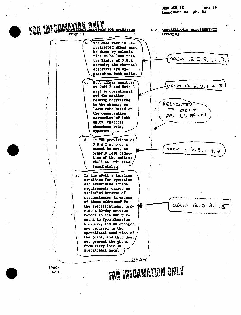
•
•
I 1 l !
\ \
\ ' \ \
· .•.
3960a 3843A
5.
b. The dose rate in un-
d.
\
restricted ar.as must be slaalln bJ calculation to. be less than the lhdts of 3.8.A assuaing the charcoal absorllers are b.7- · passed on bo~ anits.
Both . gas -i tors on lJDit 2 and 11nit 3 aust a operat.hual and the monitor
. reading cornrlated to the chimer re-
. lease rate based on the cmservatiwe assumption· of both units• charcoal absorbers being bypassed.
e provisions 3.8.1..l.a, It or c
·cannot be •t, an orderlJ load reduct i ma of the a.it(s) shall'be initiated imediatelJ.
)
DRESDEN. II DPR-19 Amendment No. ~· 83
4.2 SURVEILLANCE REQUIREMENTS (CONT'D)
'·
; . !
f. I
-=------,.·-·-·-·-·-·----~
0 OC m Id. . ~ , S • I • Lf; 3
R.~c 11r l"lf()
~ C>O L'f'I\
(.,-1.. eCi -o I )
-----------
.,.----:..----.--.--.-~-..-. ----J,
In the n~t a limiting condition for operation and associated action requirements ca.DBOt be satisfied because of circwi:mt:aaces ill excess of those afdressedt iin- · the specifications, provide a 3~J written report to the 1lllC .pursuant to Specification 6.6.B.2., and m e·hanges are required in the operational coadltion of the plat, and this does not prewent the _plant from entry into an operational mode~
.lil--:..-------i I ODc.i-~\ I~. 0. 8, j I-~) ·' .· ----- ... --. ---- .. -·-·- .. ···-·--
' i I.
----____ ...---·- - -. . _____ :!J~_.2::...7
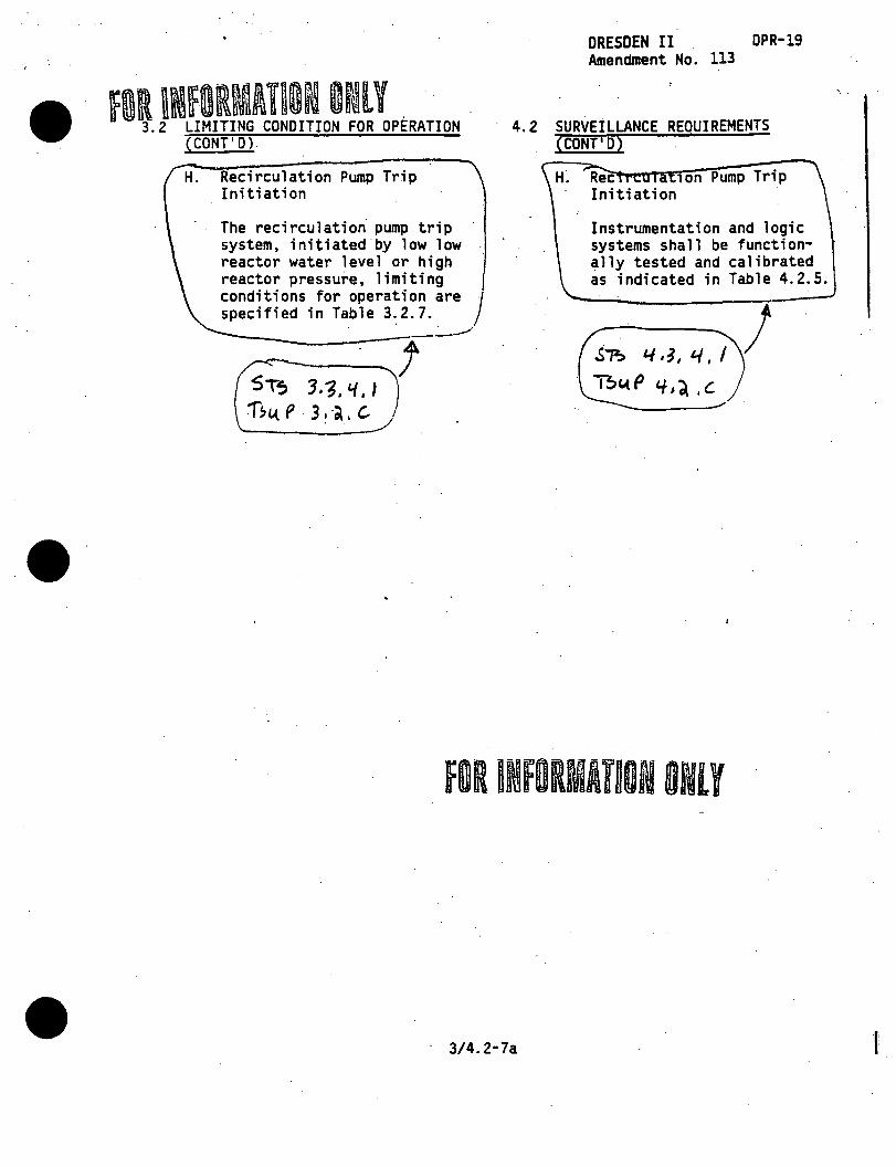
•
•
•
fOR 1Nf9RMATIOM or~lY . . . 3.2 LIMITING CONDITION FOR OPERATION
(CONT'D).
H. Recirculation Pump Trip Initiation
The recirculation pump trip system, initiated by low low reactor water level or high reactor pressure, limiting conditions for operation are specified in Table 3.2.7.
-----------:;·-~ ~s ---J T~ 3.~."f.J
1";1.tP 3,·a.c..
DRESDEN II DPR-19 Amendment No. 113
· 4.2 SURVEILLANCE REQUIREMENTS (CONT'D)
H~ Rec 1on Pump Trip Initiation
Instrumentation and logic systems shall be functionally tested and calibrated as indicated in Table 4.2.5.
£"?.> 4 , ~, 4 , I
"Bc.t p 'f I~ , C
· 3/4. 2-7a
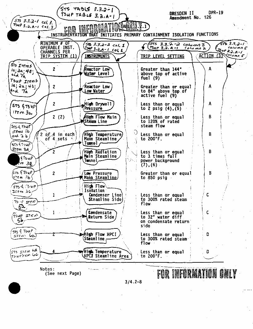
' MINIMUM # OF. / OPERABLE INST. 1 CHANNELS PER
TRIP SYSTEM Cl)
sr~ zrem$ \ If.I • a.~. "I e . o.~,A. I~ ) T~"4 p .Irtr(l!J I~; ~a.• l.fb• 11«_ 7~· J
A ·" ! ('H ..... Fl ~ i !~--.,; ~IAf'. : ! 1~ OW1._· --
) I l 1. I .
i t 1
\
' :i1e~ 3c.../ · . \ 0
l Isolation· < ____ ,,; · '. 1 ~ Condenser Line 1
;;~ . i Steamline Side i ·.. ~ _ ____,,, i . I . \~) ; ,_____ i ,..... 1
(TSIAP ~ ~------~ \ ~'1/ :- -----·,"---;
ST? ;:ref(\ 'd. ·-...~4L.-----.,Hhjli lemperature . i::> 1..t I' \rerl' c,,c, PCI Steaml i ne Area ...... ...._ ____ _
Notes: (See next Page)
DRESDEN II DPR-19 Amendment No. 126
Greater than 144" above top of active fuel (9) ·· .
Greater than or equal I ; to 84 n above top . of ,fl ' active fuel (9)
Less than or equal to 2 psi~ (4)i(5) ·
Less than or equal to 120% of rated steam flow
I i
;:) Less than or equal , to 200°F • . )
Less than or egual to 3 times full power background (7)' (6) .
Greater than or equal. to 850 psig
Less than or equal to 300% rated steam flow
Less than or equal to 32" water diff on condensate return side
Less than or equal to 300% rated steam flow
Less than or equal to 200°F. ·
FUNCTIONS
A
A
B
B
I I
I
B \ ' !
B
' c '
c
0
0
---------- ·-· -···· -·------ ..... ·----·
! i I I
I
i
....
·.
' :
/
FOR ~lfORMATION ONlY 3/4.2-8

. DRESDBN II DPR-19 ,_ Amendlllent No. ~, 83
~ ·~ ,;:.~ ~ ;~~ ~: ;:~ ~. - ... ~'.:". 3.:2 -~~~~~~ Corrected F::s~~~ 2 \ 1985
•
1. When primary. containment. integrity is required, .ther,_.D.11.!a~l~l:,...i:ta-~""-1, operable or tripped trip systems far eaob iuao•'OJU zcept for low pressure main steamline which only need be_!y_ail._•b~_lp_JJiJL.!_UH . osi y · __ ·--·--· .. ·.-··-······--····--------· ··--······ · --·- :····-·- ··- --.- ·
r,nc."orpotO..Ttcl. \l\T"O ~&&£' 3 ••• A--1 I c::otl.4.v\,, i, r.;eY1 ~ _________ __.;.·------:_ ______ . ___ . ___ ... __ .,.,,,..
5·:---·iiay .. be byp~;·S-;d Vb·;~-;~·~e.ssa-ry du'°rfngpurging-·for. confa.inme.nt .... lner-ting)-'2-and deinerting. · ·-- -·-·--·--c;--c;~T€_-;:;;;;J1,
\-6~-An ~1;~ setting of i;;;·· th·;; or equal t-;; '"J.::5··"times" ncirmal-o"ackgro~-:_.-_, \ at rated power shall be established to alert the operator to. abnormal ·"--._ radiation levels in the primary coolant.r----·-.. ----'----~-···--·····-:.~ .. ···---:(: --------------'- _:J . ~r<"'-- ..
. ~••P-•••·-···-·• • ......... · - .......... ---! 7. Due to addlUon---of bydrogeri"""totfie primary coolant, the Main Steam Line'\
Radiation monitor setting will be less than or equal to 3 times full l power background without hydrogen addition for all conditions ezcept ' for greater than 207. power with hydrogen being injected during which the Main Steam Line Radiation trip setting will be less than or equal
I 3 .~,A-! i f')()'j'f> \
-r~J~ To.'oJe) \ J.~.A ... J
tJO't"e b.
/,,,--- ---
to 3 times full power background with hydrogen addition. Required changes in Main Steam Line Radiation monitor trip setting will be made within 24 hours ezcept during controlled power descensions at which time the setpoint change will be made prior to going below 2M power. If due to a recirculation pump trip or other unanticipated·-power reduction event the reactor is below 2M power without the setpoint
1
change, control rod motion will be suspended until the necessary trip j. setpoint adjustment is made. : ... ______ :_.----··------·------------
S:-verification of time delay ~etti~g- b·;t~een · 3 --~-:d-;-~~~~~~-~~~~~
9.
3960a 3843A
erformed during each refueling outage."--·- ----·-- ··--·--------··-....... --···-:·--· . ___ ,.,,..
... --- . -- -··:·.-
Top of ac.tive fuel is defined as 360" above vessel zero for .. afi. levels used in the LOCA analyses. l.!_See ·design ·-Bas~~)\...,. --- .... ~s>;~:.~'····--·~----- ·-3/4~2~;----- · ·· - ~--. -_ ·:.--~-=~------· ~---
.; '.;. ,~ -! No-r~
...... --·-·
....., water:
I /

s~ \h.)~b.) ·\ ; b') If b.) i .
J\,(f) lb, ab,,°'; 3\,. , "~, ~"· 'I
~----
: Sr..,, ZTc.>tl"S I•,:; I '""'-' \ J,1"'1.-:_\ ~. ~
''"f.~ + .;,", I.-. \ .......
DPR-19 126
• n conJ ion w1 ow reac or ~ initiates core spray ilnd LPCI.
2. In conjin:tfon with hfgh·drywell pressure, 120 sec. tf me delay, and l• p-esare core cool Ing interlock fnit1ates auto blowdown. lnftfates HPCJ and SBGTS. Initiates starting of diesel generators.
Pressure! Less than or· equal 2 PSIG
lnftfates core spray LPCJ, HPCI, and SBGTS. ·
i
I
I \.
Low Pressure Core . ·Cooling P~ Discharge Pressure .
-tY Loss of Vol tagel Emergency Buses J
rester than or ·equal to 30D PSIG & less than or equal to 350 PSJG
·Jn conJla!Ctfon wfth low low water lewil 120 sec. time delay and low (ll"(ISsure core cooling interlock lnf tiates auto blowdown.
3. Initiates starting. of diesel generators.
1. Permissiw for c;ipening core spray lni LPCI adaission valves.
2. In con{"la!Ction with low low reactor water ewl initiates core spray and 1
rester than or ~l !\ Prevents inadvertent t;iperation of LPCI. . \: to. 2/3 core height containuent spray durinp accident
rester than or equal to 0.5 PSJG & less than or equal to 1.5 PSJG
\
conditions.
Prevents inadvertent 1?P9ration of , contail'lllent spray during accident i
)
conditions.
ess than or equal to Jn conlla!Ction with low low reactor 120 seconds water evel, high dry-well pressure
·lni low pressure core cooling \ interlock initiates auto blowdown.
Greater than or equal * Defers APR actuation pendi~g to 50 PSJG & less confirmation of low pressure core
.·rr::~0
;93~:l::o PSJG;t1• ~~:~t::s:~r~:a::0
:;esel plus or minus 5X ; generators. decreasing voltage / 2. Permissive for starting ECCS ~·
' \3. Removes nonessential loads from ; buses.
Trips emergency bus normal feed breakers.
Initiates isolation condenser ·~-.Pressure, ____ __,· 1070 PSIG for 15
"'QI ---~· · seconds
\
' {~-ained Hi~ Re~c~ \Less than or ~l to
i 2/Bus .' egtaded Voltage o;;-... Cireater than or equal to Initiates alarm and picks up tf~
J 4 KV Emergency Busef¥ ' 3708 volts (equals °' delay rell!'f. Diesel generator picks
j I
I ._/. j 3784 volts less 2X ·, up load If degraded voltage not A · · , tolerance) after less \~orrected after time delay. q / ( t~an or eq1,111l to 5 \
· minutes (plus 5X tolerance),........._ --------·, with a 7 second (plus or · ._____ ·, minus 20X> inherent time ·.delay ·
./
otes: ·- .......
3/4.2FDR INFORMATION ONLY
•
. I

'I..
1. For all positions of the Reactor.Mode Selector Switch whenever any ECCS subsystem is required to be operable, there shall be two operable or tripped trip systems. If the first coiumn cannot be met for ~of the trip systems,.that system shall be tripped. If the first column cannot be met for both trip·systems, immediately initiate an orderly
· shutd old conditions.
Need not be operahlewben primary containmen-£Tiif8Srfty. is ncit:. required.,----------~~------------~-----.:.-.:..__~~~~---
(3: Kay be bypassed when necessary dur"Ing-purgi~g-·fo~ containment inerting
or deinerting. "
an instrument is inoperable, it·.shall be placed (or ;imulated) ""in · e tripped condition so that it '!,ill not revent containment spray.
. I of active fuel is defined as 360" above.vessel zero for all 1
ls used in the LOCA analyses. ((ieeiiugn laUJI /
E· Ai~t-lc ~·::: ·~~ / ~/ . """"A- ......,.--
~CJ. p 3d. B - I "-- De \e rec( Ute h.
3960a 3843A
3/4.2-11
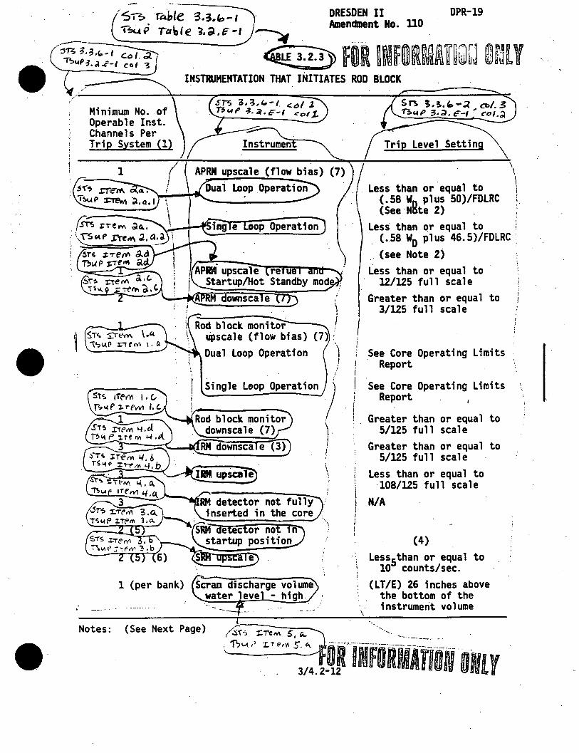
• SI~ r~{~~- DRESDEN II DPR-19 -.,_: • .n 'P"'. 1_ I ~ ""' _ Amendment No. UO '""'"''" I a., e ,,Ql.,e I ~ . ..... .
~~~. ~ fO.R ~~f.ORrv1~i~Q~j @rJlY
Minimum No .. of Operable Inst. Channels Per Trip System (1) .
1
1 (per bank)
INSTRUMENTATION THAT INITIATES ROD BLOCK
· Instrumen
APRM upscale (flow bias) Loop Operation
op Operation
Rod block monito;:--r--lipscale (flow bias) Dual Loop Operation
\ i
Single Loop Operation )
Rod block monitor downscale (7)
I \ I I
i
\
RM detector not fully inserted in the core , ~;:;;;;~~;;::- '\.
Scram discharge volume water leve - Mgh.
Level Setting
Less than or equal to (.58 W0 plus 50)/FDlRC (See·Nnte 2) .
Less than ~r equal to
\ \
\ ! i
(.58 WD pl us 46. 5)/FDLRC . . (see Note 2)
Less than or equal to 12/125 full scale
Greater than or equal to 3/125 full scale
See Core Operating Limits · Report
See Core Operating Limits Report
; Greater than or equal to 5/125 full scale
Greater than or equal to 5/125 full scale
Less than or equal to \ 108/125 full scale ! N/A ;
! I I i
\
(4)
Less5than or equal to 10 counts/sec.
(LT/E) 26 inches above the bottom of the instrument volume
Notes: (See Next Page) /.$i--s :X:TeM. s, r;... ··. ____ _
; 'PJ~ •' LT Pr(I S &\.. · --·-····.•.·-·------------·-·--
3/4. 2tR INFORMATION ONLY

· · ---·-lfffS~li.l\B ' DPR-19 fOliiORMllln-mr· az. 83. 84, 95, 104
TABLE. 3.2.3 (Notes)
This SRM function may be 6ypassed'in the higher IRM ranges when the IRM upscale Rod Block is operable.1 ---".'""----------
(7. Not required while perform.ing ow power p ysics test at atmospheric j \ \~g or after refue ing __ auower levels not to exceed ·s MWt.
/ \ I ~-·-------. -=--- . "\ ''------ - --..... t)I~ -3,3, '1 -I , uore h . ·'
'TS ~ .~ •io -I ,.lor·e ~· ' S I - " , TSc.tP~.d..f-'1 ,.,o-red.\ . n.3,~,1o-, .. otec,. ~wP3.~.~-I, Nor-eh. ----..:. _ _:J ___ /, .•~-~P 1.~.~-1, ,.Jot-e c,) ---~
_,,,
3/4.2.;.13

DllSDBH II DPR-19 • Amendment No. '2 , 83 . 1-~
fOR UUORMlfiON ONLY . TABLE 3.2.4
. -__ ..... ____ ;.,..._._~-- ... - ··-- -~··-
: RADIOACTIVE LIQUID EFFLUENT KONITORlBC·IBSTRUMENTATION
·m~, "TA;:,1e 1a.a-1 :
P.c., ICtJ I 0
"inimum No. of Operable Channels
Total Ro. of Channels Parameter Action
Notes: ...- ··- · ....... .
1 l Service Water Bffluent Cross Activity.Konitor
1
1
Liquid Radwaste Effluent* Cross Activity. Monitor
Tant Level Indicating Devices a. A Waste Sample Tank b. ·a Waste Sample·Tank c. c w,,aste Sample Tank d. A Floor Drain Sample e. B Floor Drain Sample f. Waste Surge·Tank
... -...... - _,. ........ --·-- .. -......... ~-- .·--.. ~-........ --.. ---.
Tank Tank
A
B
c
A: With less than the minimum number of operable channels, releases via this. pathw.ay may c9ntinue, provided that at least once per 12 hours grab samples are collected and analyzed for beta or gamma
· activity at an LLD of less than or equal to .lQ.:,!~~J.l.~_:_'.J.
~:c;··;~·--"wi;h·i:°~~-~;;~~-~nim~~i·of operable channels, effluent co~.Y\ 1 releases via this pathway may continue, provided that prior to 'T.~ .• ;:1, '_- .. ~ · l~' initiating a release, at least 2 independent samples are analyzed,
. _ . . , i . and at least 2 members of the facility staff independently verify f\~ · "•·i '·. i ·the. release calculation and discharge valving. Otherwise, suspend --~~__.,./ '. release or radioactive effluent via this pathway.
--------_,.---------·-··-""':'"'•--..-"'7'-·-··---··---·· A'cti~~-c:;··~tth·-1·ess-til&n-;-mriirmiimnWiiDero? .. 0pera le channels, liquid
3960a 3843A
additions to ·this tank may continue provided the tank liquid ·is esti ated during all J.!~id additio~J! to the tank.j ____ __.
~ ,,,..--=---------------·-" - ----·--.. --.... ·-·--.. -·--·-·· .. - _ .. ······-·"··~ ~ * Flowrates are to be determined by appropriate pump curves. -- -·--·-----·---· ............ -·-· ·~.-~ - --.-~· ··--" ..
~floc.o.Te& TO ODCr()
per &-1- eq -o I
~~ -----
\ .
I I

• • ••
..
•
DRESDEN II DPR-19 Amendment No. _n, J1, .91, 94
--:::::::::.:----~ll.D~f:!te~d~F~ebruary 28, 1985
TABLE 3.2.5
FOR u~formiwicf@VJ •v EFFLUENT MONITORING INSTRUMENTATION
Minimum No. of Operable Channels (1)
Total No. of Channels
2
3
Parameter
Off~Gas Radiation Activity Monitor
in imney o le Gas SPING/GE Low Range Activit Monitor
Action (2)
~ l~~ Ma1ll-Chunney SPING Noble Ga~ ... -----:-:::H;o:n:i:t:o:r:s:H:i:·d:·::H=i~R~an:g~:;:.=::::=::=:=::::: G:~ev'V'~ ~----~----~1----..._~'"Ri~in-'-c-n,rmnerprarne §a!Pler
~~--~~~~-_ __;,;:._--~....::::.::::...;:.::.:::;.:;;.t....~;;;.::;;;....;;:;;;.;;;1~;.;_------:::::::::::. ~~ 1 Hain Chimney Particulate Sampler
~_.cf 1 Hain C~imney Flow Rate Honitor
--..:_-..;;;_., 1 1 Hain Chimney _S::::a:mp::_le::r::_:F..:l:.ow,:.__----:---/ Rate Monitor -
2 aust E
1 Reactor Building Vent SPING Noble
::::::::::::::~:::;:::::!:;a~s:H~o;n;i~t~o;r~L;o;,w;,;;H;i:d;,dH;i~g~h;;Ra;n~g~e~.;:::::::::::::::;~ ~ = - 1~ ... _·~R~~~c~· t~o?.!r~!-u_u_a_i_n..:g:_v-_e_n_~_T_1_o_w_R"":"at_e __ =:=== I ---.__ Monitor~ - . . .r---., ~ ..... __ _
I !
t I I t
f I ;
Vi're~IOJ t1 ----- r-= ing ent Sampler Flow I~
B ! ., ·1
c
c
\ x:;:;;\i; 1 1ng Vent Iodine
'1· J~e"'~=:l:::::::::::::~::::::::::;;~~~;u;i~ld~i~·n:g~V:e:n:t;.P:a~r:t:i~c:u:la:t;e~~==~ 1 1 rocess Exhaust Iodine Sampler
1 HVRS Process Exhaust Particulate 1
1
1
Notes: · (See Next Page)
1
1
Sampler
HVRS HVAC Exhaust Iodine Sampler
HVRS HVAC Exhaust Particulate Sa ler
·. ___ ----=:::=;;::::----. R INfOR. Re-t.o c.,,_.tt~
\"O OCCW\
pe.r (:rt.. ~}t -o (
E
E

•
DRESDEN II DPR-19 Amendment Ho. '2, Ji5• 94
TABLE 3.2.5 (Notes)
For Off-Gas Radiation Monitors, applicable during SJAE operation. ·nstrumentation a licable at all times.
Action A: With the number of operable channels less than the minimum requirement, effluent releases via this pathway may continue provided grab samples are taken at least ~nee per 8 hour shif and these samples are anal zed within 24 hours.,.___._..--------'
With the number of operable c ess t an the au.nJJDum required, effluent releases via this pathway may continue provided that the flow rate is estimated at least once per 4 hours.
With less than the minJJDum channels operable, effluent releases via this pathway may continue provided samples are continuously collected with auxiliary sampling equipment, as required in Table
---~4.8.1.,._----------------------------------------------------------
than the minimum channels operable, gases from the main condenser off gas system may be released to _the environme for up to 72 hours provided the off gas system is not bypassed and at least one chimney monitor is operable; otherwise, be in hot standby in 12 hours.~--------..:..------------------------~~--
ith less than t e nnels operable, immediately ;;uspend release of radioactive effluents via this pathway.
it ess than the minimum nne s opera le, effluent releases via this pathway may continue provided that the minimum number of operable channels or the Reactor Building Vent Exhaust Duct Radiation Honi tor are operable. I'"-----'"-:"---------
c..~ 1'D 00 c.. W\. -E> ~
~ B'(·- 0(
----- c - ere~ FDR lllffORMATIDN OILY
3/4.2-16

515 Th~ L.t ~, 3, 1, 5 - I \P;.IA.P ~0al6" :; I~ IF- l
Minimum Number of Operable Channels Pl
1
1
1
:,2 (3) '··.
l/valve (2)\ l/valve (2) \
I I I
I 1/valve (2) :
~ .ST~ iTe M. 10 iSLA.P ~,.eM to
Parameter
Instrument;· Readout
. Location Unit 2
902-5
902-3 902-3,s·
902-2
elt rec.l I. r fL.
902-5 902-5 902-3 902-3
3/4.2-17
··~
1 2 i 2
2.
1
2
1
1 1 1 2
/! . 2
2
1 per valve . 1 per valve\
1. per va Ive \ 1 per valve
2
DPR-19 IS, 94, 102
0-1500 psig 0-1200 psig 0-1500 psig -340 to +60
foches 0-300°F. ·~
20 to +20 inches narrow ran e) -30 ft (wide range)
0 inch range {narrow range)
2.45 to +5.psig 0-5 ps·ig -·5 to +70 psi~ -5 to +250 ps1g 0-600°F 0.1-106 CPS 0-3 psid
1 to 108 R/hr
N/A 0-600°F
N/A 0-600°F
I I
I
I
.. I I
i ~

~,..., '1a.1.s-1 flr~r/Ofl ao. h isl.( P .;.a. P-1
Ac.no" '"· b
·-=-' ;_Sr; ?. ;, i, S'"' I
P,.c..T\",.J 6~. ti.
1.1P ~.~. F'I
DRESDEN II DPR-19 Amendment. No. 9 ~
From and aft.er the date that·a parameter is reduced to the minimum number of channels, continued operation is not permissible beyond thirt (30) less such instrumentation is sooner made operable. In the event that all n c ions o ame er is disabled and such indication cannot be restored in six (6) hours, an orderly shutdown shall be initiated and the reactor· shall be in a cold· shutdown condi t.ion in twenty-four (24) hours. Se' notes 2, 3, 4 and 5 for oxceptions to this requirement.
in cat.ors is reduced to one indication on one continued operation is permissiblei- however, if the
reactor is in a cola shutdown condition for longer than 72 hours, it not be started u un~il all position indication is restored
en s ion such indication ~annot be restored in thirty shutdown shail be initiated, and the reactor
than 90 psig in twenty~four (24) hours.~·--~--------------------
rom and after the date that this parameter ls reduced to eit6er-~narrow-range indication or ·one wide-range indication, continued reactor operation is not permissible beyond thirty (30) da s unless such instrument is sooner made 0 erable. n he event that e t er
-range indication is disabled, is not permissible beyond seven (7) days
unless such instruments are sooner made operable. In the event that all indication for this parameter is disabled, and such indication cannot be restored in six (6) hours, an orderly shutdown shall be intitiated and the rea'ctor shall be in a cold shutdown condition in twent·y-four (24) hours. _______________ , ________ . __ __ F'f'om amr·after- the date that one of these parameters becomes inoperable. continued operation is not permissible beyond thirty (30) days unless
,,...-- - - -- · such ins.trumentation is sooner made operable. In the event that all I -~~ -;;-;,1 . .;' indication of these parameters is disabled and such indication cannot be ; Qll"10r'\ eo.b restored. in six (6) hours, _an orderly shutdown shall be intitiated and ;· , 'T7:>1.tf ~. ~ ,f,/ the reactor shall be in cold shutdown in twenty-four (24) hours. ,,.
· ~~IOI\ ~.~,r::-----------·-~----- ----------__,--------- -- .\ r From and after the date that one of the drywell hydrogen monitors '
i51AP 3.~.f~I Acr10,.i b-. /
•
becomes inoperable, continued reactor operation is permissible. ~-,
a.
b.
If both drywell hydrogen monitors are inoperable, continued reactor I operation is permissible for up to 30 days provided that during this time the HRSS hydrogen monitoring capability for the drywell is operable.
\
I If all drywell hydrogen ·monitoring capability is lost, continued l
__ ·-- _r_e~~to:_:erations is perm~~~-i-~~~---~-~--u_P __ t_o_7_d_a.:_y_s_. _________ ,,)
3960a 3843A
3/4.2-18
I
I ! '
I

•
•
•
ST~ T"Ae> u::- g , 3,1/ I l - I ~"'p "TPl81..~ 3.~.'. , . DRESDEN II
·Amendment No. 113 OPR-19
Sr.s 3,3, L/, f1$14p1.J. ~Pl'lic AlP1/ 1ry
CUJ~-tt:J'l't""'1l"tlf 'ff"--H+"""'--...
sr~ '1. "3~ 4, r- 1 c..o 1, c;t 1~P-;, ~. c. - I co I ~-
Trip Function Mi~imum Number of Operable or Tripped 1
\Instrument Channe 1 s I \Per Trip System (a) i
Applicable Action
High React.or
I Pressure
~ow low \ Reactor Water
level
2
2
\
l (GT/E) 1230 psig & (LT/E) 1250 psig
(GT/E) 84:. inches above top of active fuel (b)(c)
Operational # Mode
1 (d) 70
1 (d)
===::::::=~~:=::::::~--t==:::==:=====~~~~ I sT~ ~~·"' ~H"'p3,a, '-' \ I ,
---·---· A'-"T'1011.J5 I,_,, 1, '1 1 -iwiil C"'.J ~~----~~--~~~===
The minimum number of operable trip systems shall be four, two high reactor pressure and two low low reactor water level, except , that one trip system may be inoperable for up to fourteen days. \ If one trip system is. inoperable for greater than fourteen days,
1 or if any two trip systems are made or found to be inoperable, the J reactor must be placed in at least the Startup/Hot Standby Mode in.
' th~ next 8 hours. · · J ~- .. _______ ;
NOTE: rS°3~"3.L/, 1 ·/. f\nd T~ P 1,;,::,1 Nore (.Q.) ,
1 ________ ::_:_J
f·~ channel may be pl aced in~~ noperab le status-~;,:-:;- to--·;- hours for/ required surveillance without placing the trip system in the tripped J condition provided at least one operable channel in the same trip ·;
\ system is monitoring that parameter. . ......... ----- . .
~f active fu;l~ff'~ed to be 360 inches above vessel zer~ ~
~ Tfie frfp--~TiTocCUF-foTTowfng·a -(GTlE) 8 & (LT /E) 10 secondde~ =============-----=-~~__:~.:__~-----~-MODE 1 is the RUN MOD~
~· -rsuP ~.~.c~I)
.· IJOT'l:" ( e) . T~ IJ. fl 3 ' ~ . c - I IJO'r~-<:2 ___ /'
· 3/4. 2-18a
.. __,,··

•
2.
3.
4.
(table cont'd saest paae)
·ar (1
(1) (13) .. p> .. 1) .
i\(1) (3) (1) (3) (2) (3) I '
r,;:::::(2) (3) L;~
.. , " ·--. ··~~- -·
.;·
(7) '· I,
\
lnce/3 Months Gnce/3 Months llla/J llontlls
. (13) lla/3 Months · Oaca/l Months
llf•l Outage lnct/3 Months llfuel Outage
-lone -........ \
Once ev1ry 1 18 80nthS '.
•n• I Once every \
18 11Dnthd
Once/Day . lone lone
None .... lone
nce/3 •nths Noni
Monthly.
None None
(2) (2)
None
Once Per 31 Days
Once Per I . 31 Days
I Once Per j · 31 Days: Once Per /
31 Days~
I I

?
Table 4.2.1 DRES1B1 II DPA-19 MINIPU'l TEST AND CALIBRATION FREQlENCY FOR CDRE - lnencbent No. ~· ~. 94 9 0 a>NTAINMENT COOLING SYSTEMS INSTRll£NTATION, ROD ILOCIS, AND ISOLATICIG (Cont, d)
Jnstnnent · Fmctional Test
Refueling outage (1) (1) ,
(1) (3)
calibration Instrunent
Check
/__ eactor Bu11d,h9 Vent 150 a on a j · 1. Refueling Floor Radiation fllanitors
· ~.,-5-.T~~;;~-~~-~;,/·J I:~~;- (oQ "b, f bd 1·s I J
1A.j)-O:u,bl~ 11.~.P.-1,l"re.~ .. c,,~ l.b " STs~~l.E &f.'!.;>.,1-11 ntllt'\ ~e -- NO~~:---tr"or Ta e 4.2.1) l~\olf'.tC4ble 't.cl.~·l ,tl"tM ac\, .,,_..52-
1. Initially once· per month until uposure hours CK as defTned on Figure ) 4.1.1) is 2.0 x 10⁵; thereafter. according to Figure 4.1.1 with an interval not less than one mon~ nor more than three months. The compilation of instrument failure rate data may include data obtained from other Boiling Water Reactors for which· the same design instrument
~ operates in an environment similar to th.at of Dresden Unit 2 •..
f 11.nor po•(•' 1., 2. Fune ion est calibrations and instrument checks are not required when
• tJ ~~A i!> '",_.1 \ t e se instruments are . not re~uu·".PY....!i£...!!S;..Ji~~.....,.~i.u.;...JUi.;.s;.....kl...u~'1!..:.--C:::: ~ pP~.-i;>."i 1)~ 11\1' \ 'lrunctional tests shall be perfomed before each startup with a
\oP~~~ lC- ~ Y required frequency not to exceed once per week. Calibrations shall b~ ~;or .,.c..'0 1 1;1~/j perf~rmed during each startup or during controlled shutdowns with a
· 11 ~ 11 c"" __.. / requ1re·d frequ.ency not to exceed once per week. Instrument checks · 1 ~·- · . .- ,,..: shall b.e performed at least once· per week. U1strument checks shall be
/-~- -··--~ performed at least once per daJ during those periods when the.---/ 1~~~/~' Cl~ f'(,A,) - instruments are requi~ed ~be ope~able. r -·----: 1·::u,, '"';,!~ ··-· ~~i-~--t~~-t;Wtl'eiila"£1on ... is exceptedf;~;···tbe-~f~~cti~nal test-defl;i~ \. ~.;. ,:-j The functional test will consist of injecting a simulated electrical ) \ c. ~i· ~. ;~~-<-' signal into the measurement cha~el. ---~---.--~~ a-'.
4. These instrument channels will '8 calibr~ted using simulated . Y. l' electrical signals once every t:tar.ee: months. In addi Uon, calibration\ '\
i n.~J~~tn.& .th.e .. sensor.s .. Jd.l_l _b._! performed during each refueling outage-~ \
,.
_,.,,.....-·"'-·. -·-· , --·· .. -. ··-·····-~·-·-·-·--· ·- --· ··---.. --.:..:.:·::;... __ .··--···-·-·-·------~---·-.. .-.... ...•.. . ;. '.· 5. A . • ft h l ' . '~d ~ . -----m1n1mum o wo c anne s 1s require . ",--..:.·:· .--------... . ..- .-.,. . r. ;
3920a 84010
(Cont'd. next p~- -·-·C-~ --~/
3/4.2-20
f Orlif OllMATIOff Oil Y

DRESDEN II. Amendmer.t No .
DPR-19 ;z. ~. ;4 9r
. ~c?_ ecA v ~: (For Table 4.2.1) (Cont'd._L----~----=-~~:::..._-------~ ~---~---·······--·····-····-····----·--- ' r 6. From and after the date that one of these ,_rameters ( ..• either \
\ drywell-torus differential pressure or torus water level indication) \ ' is reduced to one indication, continued operation is not permissible · \\ . beyond thirty days,. unless such instrumentation is sooner made \
·operable. In the event that all indications of these parameters \
I ( ... either drywell-torus differential pressure or torus water level) \ . . is disabled and such indication cannot be restored in sh (6) hours, ,
\ an orderly shutdown shall be initiated and the reactor shall be .in a / \
. \ cold shutdown condition in twenty four hours. · J ~- ~ '. runctiona1 tests v111 be conducted before st.artup .·.t ·the end of_ eac·h~ ~ · refueling outage or after maintenance is performed on a particu~
· \.__Safety/Relief Valve;r- ·. . _____ ..... ·
8. \If the number o.f posltioii1naicaforsTs reduced to o-;;-indication on ~-----.J one or more valves. continued.operation is parmissible; however. if
~uf 3>.?..F='..- the reactor is in a cold shutdown condition for more than seventy-two f't-l.r1oA f,~a. hours. it may not be started up until all position indication is ) a...1vl b-; b restored. In the event that all position indication ls lost on one or
\
more valves and such indication cannot be restored in thirty days, an . orderly shutdown shall ·be initiated, and the reactor shall be ./
\depressurized to less than 90 psig in 24 hours ... -----···-·---·-..-·-··· .... ·-- -·· ·- ·····--- ---- ---·------- i --~
9. The functional test -;;f·-·th;-S~;;;--Oischarge vol:me the;;al switches is ~ not applicable; i.e .• the switch is either on or off. Further, these \
-----ii~ switches are mounted solidly to the device and have a very low I probability of moving; e.g., 'the thermal switches in the scram / discharge volume tank. Based on the above, no calibration is 1required/ for these instrument chann~- · - · ./
10. r=~::~~~~~~~!~:!~:::~!di:~~~::~f"~:!!Y.-~!~~:~::~ .::~~·:.!~ operation of the degraded voltage 5-minute timer and inherent 7-second )
3920a 84010
\timer . .::...__ -----~---~·-~·--- .. · · .____ ____ _,.
"VtfrTfrciffoio·rttme-ailay setting bet;een 3 and 9 second~ -....,:P~e::r:..:f:.:o:.:rm:.=.:e::d:....;d:.:u~r..:.i.::n-...-. ... ..:..-.:r:..:e:.:f:..!u:..::e:..:l:..:i.::n~g-=-ou:.t=:.;a,,,.gia.:e""' . .__-----:----:-----·-~--·
3/4.2-21

•
I I
\ I
(2.~\0C~\t'.c}. 1-\ OL)CVV\ pe l$\... ecr · or
DRESDEN II DPR-19 Amendment No. fl, fJ g ('
. ·----·------·---:----:..._ -------- . -----~----·-··-··--· . TABLE 4. 2. 2 -
RADIOACTIVE LIQUID EFFLUENT MONITORING ·1NSTRUMENTATIO~ SURVEILLANCE REQUIREMENTS
·---·-----..... ..,
Instrument Calibratlon Instrument Check (1)( 7) (1)(7)(3)(4).
.~ .... &.
~~---~~--Liquid Radwaste
Effluent Gross Activity Monitor
Service Water Effluent Gross Activity Monitor
Indicating
a. Sample Tank b. B Waste Sample Tank c. C Waste Sample Tank
,! d. A Floor Drain Sample ,, Tank :.I
~ !
;j e. B Floor t>rain Sample
i.
Tank Waste Surge Tank
Notes: (See Next Page)
3960a 3843A
D
D
D R D R D R D R
D R
D R
314.2-22
i I
Functional Source . r
.t
Test (1)(2)(7) Check (1) 1 i i
~ i I
Q (6)
Q (6) R
Q NIA Q NIA Q NIA Q NIA
Q NIA
Q NIA

\ i
\ \
\ !
1.
------·---. --··. .
TABLE 4.2.2 (Notes)
D = Once per 24 hours
~ M = Once per 31.days Q = Once per 92 days R = Once per refueling s = Once per 6 months
The Instrument Functional Test shall. alarm annunciation occurs. if any of applicable.
DRESDEN II Amendment No.
DPR-19 p.1}1aD
\ a. Instrument indicates.' levels above the alarm setpoint. \ b. Circuit Failure. ~---~ \ c. Instrument. indicates a downscale failu~e. \..__d. Instrument controls not set in OPERATE mode. ~
·cr:·-~---c-~"-i_t_b _-r--at-. -io_n_s--h-,a-.1-1-_ ~-C-n_c_l-~-d.-e--p-e_r_f-~-~-~-;;--c_e_o_f-.-a--functlOnal ~~ ~ 4. -ca.:fli>r'~ti~~·-;b;ii"· i~~i;d;-performance of a sour~e chec_9~
·-s-o·urc-e""check-Shaii""consist• tff' observhig ilistr"ument r~sponse during a')
:;:::;:::~.:e•rmay •e·pe-.'to~g trrp -iili:Ck -~;;i t;.·t ; =::'~;; associated with the monitor chassis .. --= _,...,,_, ____ .. _~,~-····,.,~........-/ -----..-- - -----··· ... ·,., •• _._,J LJ5o,.e (~' . r'. Panct:iou t:est caUbl'lhons ana instr~ent~kS"'Ue-·1\'ot required wh;;'.
these instruments are not required to be operable or are tripped. ~ •. Calibration shall be per:~~~'!'!~ on_:.~ eer. refueling outage an~_,no~ _m_2_~,!. -~~_an;·
_once every 18 months. nstrumeri't: cne'Cks sliall be performea atleast ·once) . . ... a· u . . ose periods when the instruments are. required to be -- ..... · operable. · ·
3960a 3843A
3/4.2-23

---DRESDEN ~I DPR-19
·-----~~dment No. J!, jZ, Jd, "5,'. 94,
. -------TABLE. 4.2.3 -·--....
RADIOACTIVE GASEOUS EFFLUENT MONITORING INSTRUMENTATION SURVEILLANCE·REQUIREHENTS
( \ i
Ins.trument Instrument Check (1) (6)
Calibration (1) (6) (3)
Function Test (1)(4)(2)(6)
Source Check (1)
\
i I
~.
.:.::..-------------....;...----·· :§ (\ ffd' \ 10 . ·~ . i /Reactor Bldg Vent · · · D . Ji r-..E . · Q Q _)
~__.~i "'~,,.~ ,. '~~:-:::--=-·------~-::::::::::::===----------~_-_::_. -... :==: · ' ~· Reactor Bldg Vent D · . R~ Q M \ .·5)----; ; SPING Noble Gas - ----.i:.-...... _ ...... :, ~~1 : . Monitor Lo, Mid, ( ...-----·. ; \High Range __.) . _;.,....-.--- ·""'.""-----.. ______ __
' (Hai'nCh~eyNOble----~ ... D @"® Q H
\ Gas Activity H.!mitor -~·-=-=-::.:.:-·::-::-:.:--::::==~;:=========:::::~ ' aiii"-nI"mneY-sPING, D ~
' Noble Gas Honi tor . . Q
Lo. Mid, Hi h Ran . . ·
I N/ """0 ( tfain ··chrifu)ey--.. ·-·· ·- ··-··· -·~ · ·n ·-u.f · --·-·-·--·-.NiA-·-·- ··-··· N/A .·~ Particulate and ·'---·~···--../
--~----~0 . J:.:re"t. .lQ_dine Sal!!P)&:r___./ · --..._y . HainClilimey"'Tlow----·-··n··------···----~
Rate Honit Hain ~-;y;·-Sa~le;··---,, .. ,D ... _. ___ R4-(E) Q (5) N/A)
·· Flow Rate Monitor ------------~----~--··--··--~-'c=ea=c=t=o=r~B~l~d~g::;;:en=:t::::::::::::::=~D··~~--~---R-~---~--~~~Q~..:-~~-~Nf A
F,low Rate Honi~or -,-. ---- ___ /;
Reactor Bldg Sampler Flow Rate Honit
HVRS Process Exhaust Iodine and Particulate Sampler
HVRS HVAC Exhaust Iodine and Particulate Sampler
'-... - -Notes: (See Next Page)
D
D (7)
D (7)
Q 5
N/A N/A
N/A N/A
3/4.2-24
N/A ~
N/A
I !
I

_______ ..;; ..
'Amendment No. ~, f3, ~ B3
··-----··--·--_...-------·-.. ·--··-··--··. ·-·--·---·---·-·----·
D = Once per 24 hours M = Once per 31 days Q = Once per 92. days R = Once per refueling
TABLE 4.2.3 (Notes) -·----------.
··· ...
The Instrument unc 1onal Tesl shall.also demonstrate that control room alarm annunciation occurs, if any of the following conditions exist, where applicable.
a. Instrument indicates levels above the alarm b. Circuit Failure: c. Instrument indicates ~downscale failure.· d. Instrument controls not set in OPERATE mode.
Calibration shall include performance of a functional
Instrument c ec o verify operability of sampler; place and functio~ng properly.,.-~~~~n~o~~~e~(~.~~)::-:iiir~~~~~~ ....... ---
....,.. ... ___ ··--··· ·--~· ............. ·---· -.~~-~-. -.-•.u:w;: • .,J_.__:;;:__;_ . ~ 5. Function Test shall be performed on iocat· swiTthe'S"'"l'J'n:nri"lttnt-row flow'
6.
lann. .
unction test calibrations and .instrument checks are not requ ~ ........... i these instruments are not required to be operable or are tripped. -.. 1 Calibration shali be ~erformed once er refueling outage and not more than_,} \Once every 18 month~ Instrumen checks. shall e per orme at eas once\ per ay uringthose periods when the instruments are required to be operable.
~--------.,..---------------~----------~--~~~~·---ht~st;;~;nt"'7h;ck t~ -;e;irY-~-erabTITt;·;f s:O-;;;;·~·thatth~" (. place and functioning properly prior to use of the.Mobile Volume, Reducti~!0
~··~~~~--S-).:~~=·--~.~====---=·~---~-------.. ---------~/
3960a 3843A
.fl-(' loCti.T.e0 r;: r
3/4.2-25

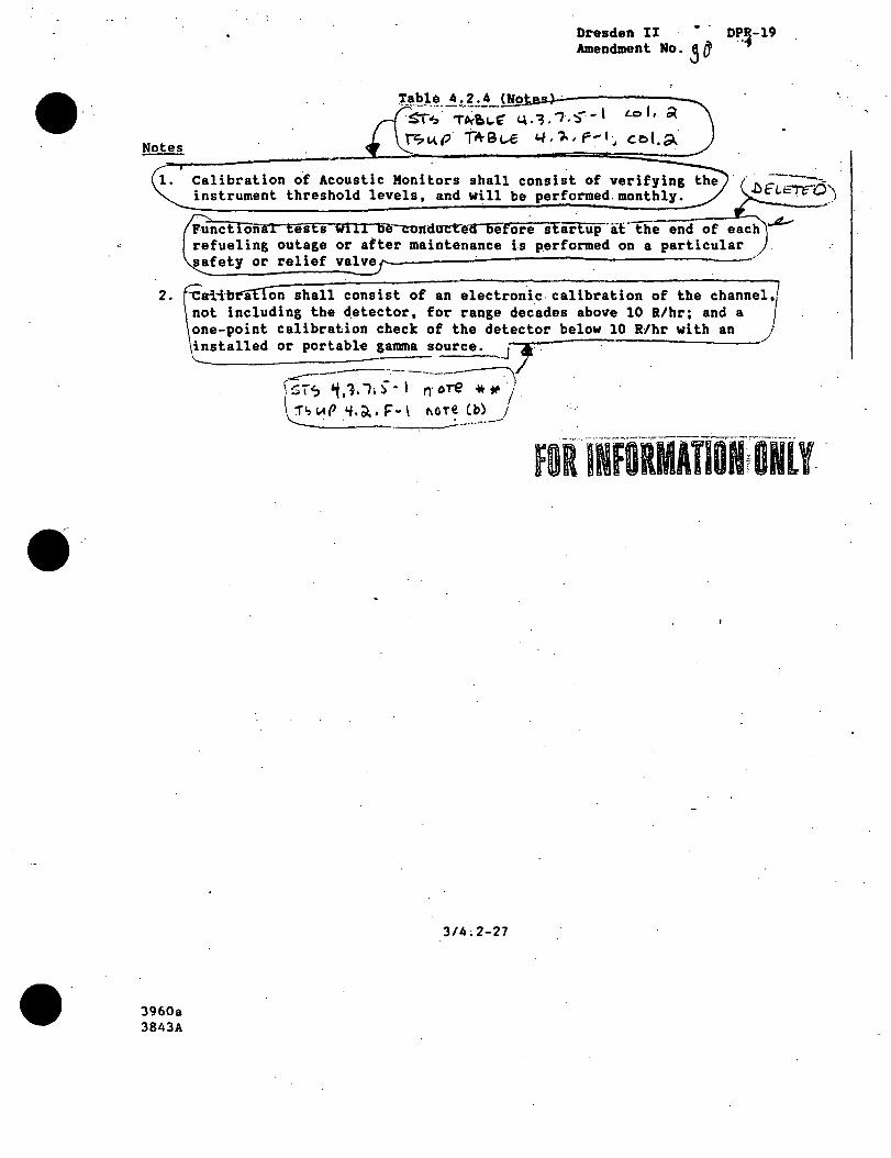
•
Dresden II DP.~-19 Amendment No. 3 O'
1able 4.2.4 ~(N~o~~~~----~----~ -~s:r:.:· -.;;~~" ~,'. '1.:) - I Lo I. Ol \? !.( (.i Tit- B (....€ 4.# • ;. , F ".' I J c r:> (. .9..
Calibration of Acoustic Monitors shall consist of verifying threshold levels, and will be performed.monthly.
::-::-::-r-i~,.,....--=-=-=""'w..-.......... ......,.e-comturt"ea-Defor~ start:up·af"tile end of each ..4-or after maintenance is p_erformed on a particular valve,,..._~~~~....;...~--~~~~~~~~~~~~~
....__~~~~~~~--_.,
2. ~-ca·H·bt"&£ion shall consist of an electronic. calibration of the channel,/ ot including the detector, for range decades above 10 R/hr; and a / ne-point calibration check of the detector below 10 Rlhr with an / nstalled or portabl~ ganuna source. J-. /
3960a 3843A
-:------------:.--~,.( l::;; r" 't, 1. l i :) - 1 n· ore * * I ~IA(> 'f,~, !="-\ M~-~-~:._)
3/4;2-27
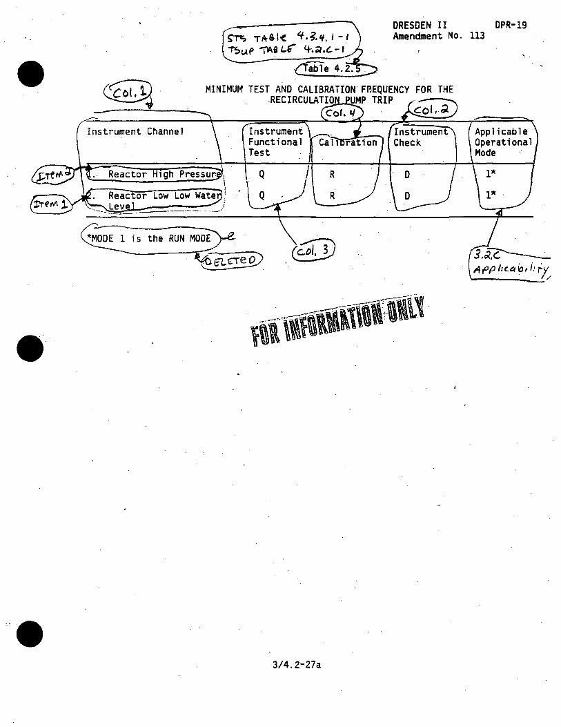
Instrument Channel
Reactor 1gh
S'T'; TA-61'( '+.~.'/.I - I ~<.Af ~i (.."" 4-.01.t.- I
DRESDEN II OPR-19 Amendment No. 113
MINIMUM TEST AND CALIBRATION. FP.EQUENCY FOR THE .RECIRCULATIO UMP TRIP ----
Instrument Functional Test
I
3/4.2-27a
R
R
. col,;(
Applicable Operational Mode
l*
l*
3.~ Af'P lie~ b1 i1 r'/,

, ....
Applicability: . . .
Applies to the plant instrumentation ~hich performs a protective function. ' . \
Obje~~ive: ..
To assure the operability of protective instrumentation.
Applicability:
Applies to the surveillance requirements.· of the instrumentation that performs a protectiv~ function. -
Objective:
To specify the.type and frequency of sur-· veillance to be applied to protective
· instrumentat · ·
SPECIFICATIONS·._ ~-===:::::::::====~~~~--~--.:.__ ------~======::;:::_Jr__~__:.-
A. Primary Containment Isolation Func A. Primary Containment Isolation Functions
s~ 3.3.~ TSw P 3. a,. r.,
tions
When primary containment integrity is required, the limiting conditions of operation for the instrumehtation that initiates primary containment isolation are given in .Table 3.2-1
The limiting conditioni for operation for the instrumentation that · initiates or controls the core and containment cooling systems are given·
·in Table 3.2-2. · This instrumentation must be oper~ble when the system(s) . it in·itiates or controls are. required to be .operable as specified in Speci-fication 3. 5. ,___ ________ _
ock Actuation
.1. The limiting conditions of oper ation for the instrumentation that initiates control rod block are given in Table 3.2-3. ·
3.2/4.2-1
Instrumentation and logic systems . shall be functionally tested an~ calibrated as indicated in Table 4.2-1.
B. Core and Containment Cooling Systems -Initiation and Contrail .
Instrumentation and logic systems shall be functionally tested and calibrated as indicated in Table 4. 2-1. ;·
• Control Rod Block Actuation ~ Instrumentation and Logic systems ' shall be functionally test~d and calibrated as indicated in Table 4.2-1.
.·Sr-:> 4,3, c.,.
TS41" 4,o.€
Amendment No. 114

·,.. .-
The minimum ·number of operable· instrument. channels specified. in Table 3~2-3 for the rod block monitor may.be reduced by one in one of the trip systems for maintenance and/or testing, provided that this condition does
· not last longer than 24 hours i"ri any 30•day period. -If this condition exists for more than 24 hours in a 30~day period, the system sha 11 be tripped~
Refueling Floor a 1at1on 51'11mitors
1. Except as specified in Specification 3. 2. D. 2, the two refueling floor radiation monitors . shall be operab1e '6e:m.ever irr.adiat~d fue1 or componet!'lts ·are · present in the fuel storage pool and during refue 1 i ng, or fue 1 movement operations. '
2. One of the t'r#O refueling floor radiation monitors may be inoperab 1 e for 24 hours .. · If the i noperab 1 e monitor i,s not re• stored to service in thH time, the reactor bui iding venti lat'ion system shall be isnl~ted and the standby gas treatmemt aperated · until repairs are aimplete.
The trip se rn or· e refueling flo.or radiation mmitors sha 11 be set at a -value: of < 10 R/hr. -
4. Upon loss of both refueling floor radiation monitors while in use, the reacto~buildirig ventilation system shall be isolated and the standby gas·treat,;. ment operated. -------
-------·--·--··;/
3.2/4.2-2
v
D. Refuelirlfl!:Flloor Radiation Monitors
r~ ~~'-" .?.1, ~ - \ LTeM «,e,
' ' ~f Thei \e '3.1~ • A - \ . ,2:'TE M -. .o\
'S~ °3•3.~ A:c..11or\ C..
. 'tiu.P '3.~.A ~C.TIOw ~
srs ~alt. 'f,'3,~.\-1 J:Tfl'l\ ~.e.
~""f' T'Q.ble 4.~.A--1 :ne rY\ -a • °'
"f.$1.Af 'f,/, i>. ~.b.1) <J./\l ~(>L#. 7, P. "I I b I q.) ...__~----r--:------
.s~ ;-,re, 1-e '3 .• ~ , ~ - ~ ; · .. ' 'Col 3. 1~m ~.€
~ . , f . . .
. · T',)1.1,P -r~~;~ ·3',·~,A·I i
. c..01,a J :i:rc~ :;..a
Amendment No. 114

_·. ~ .
,1)\!> 3 '3 I 7 I s °ThV.t' 6.~. F' •
QUAD-CITIES DPR-29 .. Sr~ 4.1-7, 5'°
r.sl.(P L./, ~. i= , .. Postaccident Instrumentation ·e~ Postaccident Instrumentation
The limiting conditions for operation for the instrumentation which is read out in the control room, requ.ired for postaccident monitoring are given in Table ·3.2-4. · ·
. . -Postaccident instrumentation shall be functionally tested and calibrated as indicated fn Table 4.2-2.
ontrol Room Ventilation System Isolation ·
· ·l· . Control Room Ventilation System Iso. latfon
1. The control room ventilation systems are isolated from outside air on a signal of high drywell pre~sure, low water level, high main steamHne flow,. high toxic gas. concentration, high radiation iri either of the. reactor building ventilation · exhaust ducts, or manually. Limiting ~onditions for operation shall be as indicat~d in Table 3.2-1 and Specification 3.2.H. and 3.2~F.2.
The toxic gas detection instrumentation shall consist of an ammonia analyzer with a trip setpoint set at ~ 50 ppin:
The provijions of Specification 3.0.A. are not applicable.
3.2/.4~2~3
Surveillance for instrumentatio which.~ in·itiates isolation of · control room ventilation shall be as specified in Table 4.2-1
2. Manual.isolation of the control room ventilation system shall be
·demonstrated once every refueling outage.
· T~v.P LJ 8 c-1, ''O .~. b
Amendment No. 140

G.
'·.
•
- ... ···-QUAD-CITIES'
DPR~Z9- .
Radioactive Liquid Efflumt Instrumentation
The effluent monitoring instrumelita tion shown in Table 3.2-5 shall be operable with alarm setplrints set to ensure that the limi:ts of Specification 3. 8. B. are not excarded. The alarm setpoints shall be atermined in accordance with the· OD... ----
1 a rad1oact1ve quid ef-fl uept monitoring il5trument. alarm/trip setpoint less conservative than reqlilred, without delay suspend the rellease· of radioactive liquid effluents monitored by the affect.Im instrument, or declare the iiRstrument i noperab 1 e, or change the set- . point so it is acceptably conservative.
2. 1th one or more raifioactive ii. quid effluent monitati.ng instruments i noperab 1 e, take the ac·.;. tion shown in Table 3.2-5. . Exert best efforts \fl) return.the instrument to operatrTe status . within 30 days ands if unsuc-
. cessfut, explain ia the.· next Semi-Annua 1 RadioactWe-· Effluent Re 1 ease Report why tile. i noperabi lity was not corrected in a timely manner. This is in lieu of an LER. r.---,.-..,.__.;._ __ __,_
In the even a· 1 imiti!r\'gi condition for ope rat ion and associated action requireaents cannot be satisfied because· of circumstances· in excess Gf those ad"." dressed in ·the speaifkat ions, provide a 30-day witten report to the NRC, and no &hanges are required in the Qj>erational condition of the plmt, and '·this. does not prevent . th!' plant from · entry into an operational mode. ·
3_.2/4.2-4
G. Radioactive Liquid Effluent Instrumen~tion ·
. Each radioactive liquid effluent .mon _· itoring instrument shown in Table . . 4. 2~ 3 shall be demonstrated operab 1 e · . by performance of the given source check,. instrument check, calibration,.· and functional iest operations at the frequencies shown in· Table 4.2-3.
. DDc..M Gu.A-o c:,.,T,~.;. At.JN~
\~ .. ~. ,; ~- ----
OOL iv\ .
l~.~.1.A, I
Amendment No. 114

... :=· · ..
·-=- ..
•
H.
I i
I I i i i
\ \ l I \
'
QUAD-CITIES DPR-29·
.-..• .-.... : .. -.
, .. Radioactive Gaseous Effl•mt · Instru- · H. RadiOactiVe Gaseous Effluent Instru-' 1-mentat ion _m::,e;.:n~t=a:.:t.::1 o;n:...· _· --:----·---..,.....-~ \
The effluent monitoring instrumentation shown in Table 3.2:-6 shall be operable with alarm/trip setpoints set .to ensure that the linits of Spe~ cification 3.8.A are not.exceeded. The alarm/trip setpoints shall be determined in accordance with the ODCM. ,__ ________ _
With a radioactive giseous effluent monitoring iastbrument alarm/trip setpoint less conservative· than requind, without delay suspend the release of radioactive gaseo.us effluents monitored by the af fecteml instrument; or declare the instrument inoperab 1 e, or change the setpoi nt so it is acceptably con-
rvative. · · .
2. With one or more rad.1oactive gaseous effluent monitoring instruments inoperable, take the action shown in Table: l.2-6. Exert best efforts to return the i nstrliment to operable status withiri 30 days and, if unsuccessful, exp 1 ain in tile· next Semi-Annual Radioactive Effluent Release Report why tile inoperabil ity was not corrected in a timely manner .. this is in lieu of an LER. · · · ·
l n e event a 1 i miting condi-.t ion for operation and associated act ion requi rments cannot be satisfied because of circumstances in excess flf those· addressed in the. spedficat ions, provide a 30-day written: report to the NRC and no clang~s, are required in the operationa 1 . condition of the. plat, and .this· does not prevent the p 1 ant from : . entry into an operational mode.
3.2/4.2-5
Each radioactive gaseous radiation ·. ·· 1
monitoring instrument in Table 4.2-4 shall be· demonstrated operable by · perfo.rmance of the given source
. check~. instrument check, calibration, and funetional test operations at ·th frequency shown in Table 4.2-4.
·fOfflifORMATIONfONlY . . - - ~~ .
Amendment No. 114

QUAD~cmES. srs ~e.(e ·a.3.a.· I DPR-Z9· Ts·IA..P The.ie 3:~. A-1
-~ . -INSTRUMENTATION THAT INITIATES PRIMARY CONTAINMENT.ISOLATION FUNCTIONS
Minimum Number of Operable or Tripped · Instrument Channels [1]
:srs ~T~ctP n-ef\\ Sr;,
\ 4
Low main steam pressureC4l
High f ow RCIC steamline
steamlin
PCI area high-temperature
Steamline pressure
Trip Level Setting
>144- inches.above ·top o active fuel* ·
>84 inches above top of active fuel*·
~2.5 psi_g [3] A
~140% of· rated steam flow B
<2DD°F ( B
<15 x norma 1 rated power ; B background {without ·hydrogen addit.ion)
>825 psig B
·<300% of rated steam I c 1le>W[7]
<170°F c
<300% of rated steam . -1'1ow(7]
D
<170°F
>100 psig
[1] Whenever primary contai nmen.t iritegri ty is required, there sha 11 be two operable. or tripped systems for each function, except for low pressure main steamline which onlyneed be available in the Run position .
. . .
51-s. ~. 3 . .a; ALT10"!> b ~ C..
T? IA p 3' d. A . A c. -ii Ot\ 5 ~ 1 s . ,) I
3.2/4.2-15 Amendment No. 139
,.
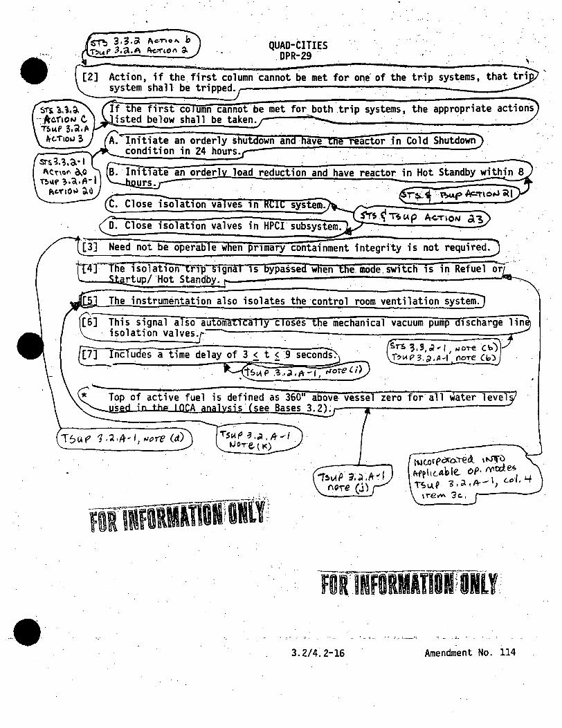
~ 3,3,a Ac:-T"lo,.. b T~uf 3,a.A A<-..~UH\ a. QUAD-CITIES
. DPR-29 .. ~---.-~-_........., ___ _...;.. ______________ ;....__...;,_.----:-.....;'
~1l. l.l,~ ---:-:A°C.flOt.I C ·nwP 3.~.A
ttc... i-101.J ~
srs~.;.a.-1 l\Cr1ofl 0.0
ni1.1t> ,.a.A· I ~c.1'10 ~ d.u
Action, if the. first column ·cannot be met for one of the tr-i_p systems, system shall be tripped. · ·
If the first co umn cannot be niet for both trip systems, the appropriate isted below shall be taken. ·
reactor in Cold Shutdown
Initia e an orderl load reduction and have reactor urs. ·
Close isolation va ves in system.
Close isolation valves in HPCI
Need not be operab e w en primary contafoment integrfty is not required.
·-4f""lhe isolation trip .. signaf is bypassed when the.mode.switch is in Refuel or __ .. rtup/ ·Hot Standby. ,.__------~-~-~--------Jt.ia-,...
The instrumentation also isolates the control room ventilation system.
This signal also automatically closes the mechanical vacuum pump discharge lin~ isolati~n valves~
___ rnc udes a time delay of 3 it i .9 seco~
·· . · .. q:fP .~ .. ~.tr-1,~V
-rsc.t~ -1 .~ • .;r .,,, tJ OT·e, ( I<) .
.Srs 3,!11
• .. ,, ._.oT"e. Cb) B 1.q:i 3 . .;i , A ~I floT'e Clo)
l\lto r (' ac-o..-.e <l. ' t.J1f u Afphc..a.ble... DP· IY'cd.e~ lS\,\,~ '3.d.d~--1, c..erl. '"+
\T"ell'ol\ 3c.,
3.2/4:2~16 Amendment No. 114

6-rt,, ~. 3. ?-I . 1101 fl . . nuP1.J;&- 1
~•.3 ..
4[4] I
2
i i
TA-8lE 3 .. 3.'?> - I T~v.P TftSlt 3."a,. e,-:- I
\. . .,
Level Setting · Remar
>84 inches above top of active ·fuel*
1.· In conjunction with low.reactor pressure initia~es core spray and LPCI. ·
2. I~ c~njunction with high- . . drywe 11 pressure 120-second 'time delay and low-pressure core cooling interlock initi ates auto.blowdown.
·3.- Initiates HPCI and RCIC .. 4. laaitiates starting of diesel
generators. ·
1. Initiates core spray, LPCI, HPCI, and SBGTS.
2. ln conjunction with low .low water 1 eve l t 120-second ti m .
. . I · delay, and low-pressure corl
cooling interlock initiates · auto blowdown. ·
3. Initiates starting of diesel\ generators. . !
4 .. Initiates iso1ation of · \ control room ventilation. \
Permissive for opening core spray and LPCI admission valves.
I \ '
II 2. In conjunction with low low I reactor water level initiates:
>213 core height · 0.5 psig<p<l.5 psig
~12o·seconds
core spray and LPCI. f.
revents inadvertent operation f containment spray during ccident conditions.
I I I I I
\ \
In conjunction with low fow ; reactor water level, high-drywell \
1 pressure, and low-pressure core J. cooling interlock initiates auto blow-down. ~-...-·
Amendment No. 114
FDRlNFORMATIONl ONlY1

:· ..
•
Minimum Number of Operable or Tripped Ins,Yrument Channels[l] /
4
Q~R~~~res • f 01.lifUiAtlOf rNl! TABLE 3~ 2-2 (Cont'd) .
"S'r--:. 3. 3.~ -0\1 ~ol.3 . !Sc.IP 3 ·~.$-1 C-4'1.~
Level Setting
045 ±5% volts
...
Defers APR actuation pending confirmation of low-pressure core 1:ooling system . . operation.
1. Initiates starting of diesel generators. Permissive for starting ECCS p~s. Removes nonessential loads from buses. Bypasses degraded· voltage timer. i
J i ·-. 2/BUS[S] 3840 VO 1 ts ±2% . with 5 ±5% minute time delay and 7 ± 20% second inherent
Initiates alarm and picks up : time delay relay. Diesel enerator picks up load if egraded voltage not
! i \ ~ \ ____________ _
time delay · orrected after time delay. . . . I .
.STS ;:;,-;1AC.r1011 b; . . . 7!.uP .?.a. 8, /tC.Tl~ft a; ST~;.~.3-1 ALTJ011s.30;o36 T!>4{P3.J.e-1.A<-1"1Mt; 30,3(;:,
For all positions of the reactor mode selector switch (except for the .containment· interlOck}whenever any ECCS subsystem is required to be operable, there shall be two operable trip systems. If. the first column cannot be met for one or both of the trip systems, the systems actuated shall
------ \"':~..w.e eclared inoperable and S ecifications 3.5 or 3.9 shall overn.r----.-/
e operable w en primary con ainmen integrity is not require .
an instrument is inoperable, it shall be placed (or simulated) in the tripped condition.so that it wil nt containments ra.
There are a to a o eight high drywe 11 pressure sensors. Four are used for · core spray and LPCI initiation, -and four are used for HPCI and auto blowdown initiation. This specification applies to each set of four sensors. ·
... _,._•~·--.--......;,.--· a·--· -[5] With the number of operable channels one ess than the total number o Dfle.Te
channels, operation may proceed until performance.of the next·required functional test, provided the inop~r~~le __ c~~fl!l~_l_ .i~ .PJ~~ed _ in_J~~--~fipped>~ " . ·co·naifion wit}lin-"one"'··t10ur:-----".""~- . -·~-- . - . -·----- ··--···-· ···----- ... ---·
S'T!. J,3,3 -1, Ac..T10115 38 . -· .De Jere. .1 tJ: -IS"'.' p
3.2/4.2-18 Amendment No. 114
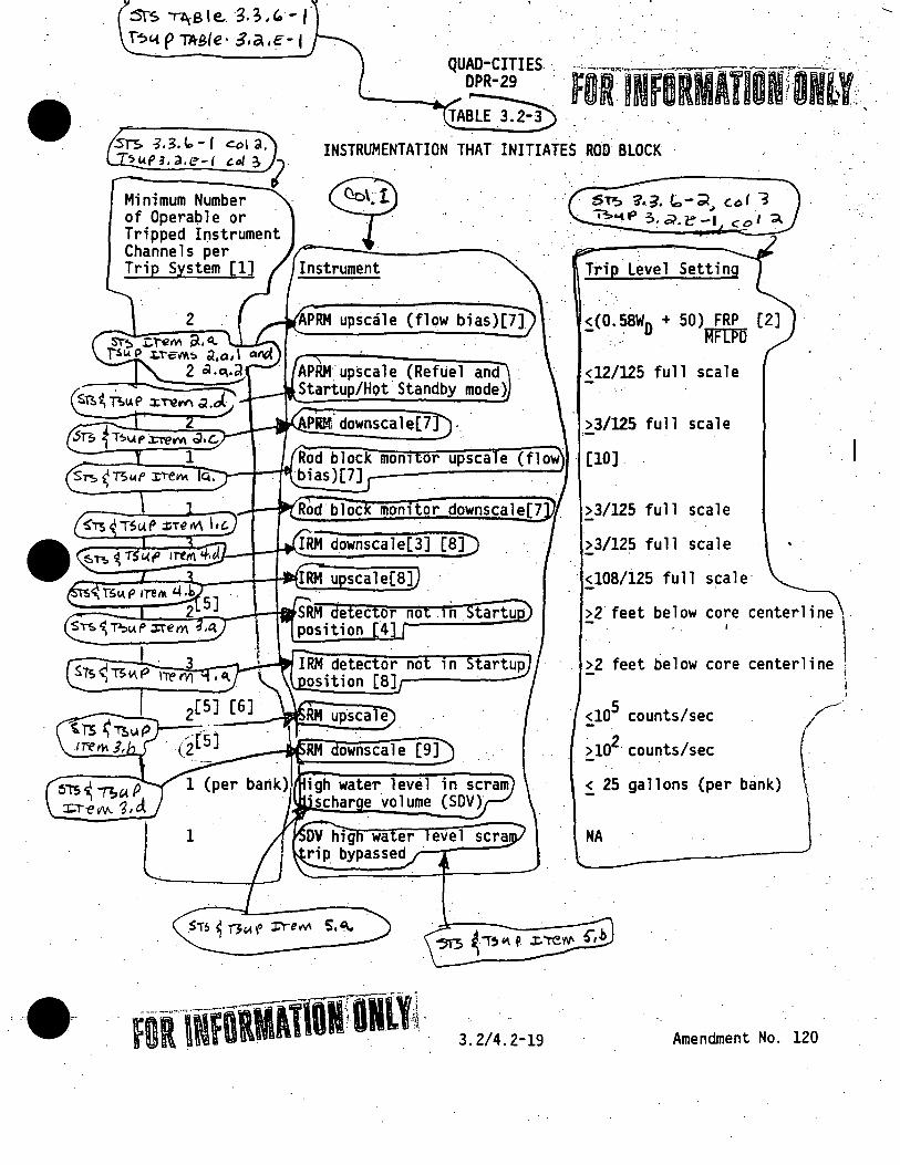
:st-s 'Tl\Sle... ·3.3,G.-j"· f~(.( p TAB(e· &.a .e-1 ·
eel a. ~"'"" 3. a.e-t c.ol; ,.
INSTRUMENTATION THAT INITIATES ROD BLOCK
Minimum Number of Operable or Tripped Instrument Channels per Trip System [l]
~ · SP.:> 'i.~. ~-~ col i · ~<-4.P 3. ;;,.e-1 c:ol ";\
Trip Level Setting
~(O.~WD + 50} FRP [2] :.· . RITPll
<12/125 full scale
>3/125 full scale ,_
Rod block mon1 or upsca e (flow · (10]. ~-+---r111 bi as)[ 7]
[9]
1
3.2/4.2-19
>3/125 full scale
>3/125 full scale
· <108/i25 full scale·
..
>2 feet below core centerline
:2 feet be 1 ow co~e center 1 i ne l \
<105 counts/sec
)102 counts/sec
~ 25 gallons (per bank}
NA
Amendment No. 120
I
I
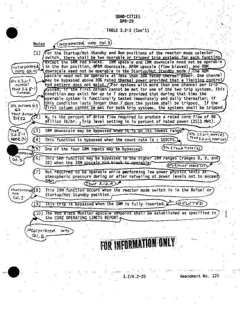
ST~ ;,-,.1.- I MTe(o.J
Th1>f' 3.~.G"-1 n urecp.)
·QUAD-CITIES DPR-29
. TABLE 3.2-3 (Can't)
W is the percent o rive f ow required to produce a rated core flow of 98 m~llion lb/hr. ,Trip level setting is in percent of rated power (2511 MWt).
IRM downsca 1 e may be bypassed '"Wh1
This function is bypassed when the count rate is > lOOCPS.
T ls ·Rw·f'Onct1 on may be Typassecr m the Iii gfier 10) when the IRM u · ler----:~:r======-~-
Not req o e operable while s)erforming low power p ys1c es s a atmospheric pressure during or after refueling at power levels not to excee
t. . (f5'-'P 3,Ja,lf>JA This IRM function occurs when the reactor mode switch is in the Refuel or Startup/Hot· Standby position.,;..-----------------~-
fully
, .
e es tab 1 i shed as speci~ J
FOfiNfOtllATION ONLY' ...
3.2/4.2-20 Amendment No. 120

... . · ..
.. : .. :·,
.': ':. ~·· ~ .,
. '. . . .
POSTACCIDENT MONITORING INSTRUMENTATION.RE UIREMENTS[2]
·1
1
1
1
1 /~usp~. @E>J~~ ...
· 2 /. Drywell p.ressure · I . : Sis :tie""~ I .,..". ,,._ .. 5 ~ ~
' \ I i I
I ·~
i
I ~~:~ l / \. . / -----~··
Instrument Readout. Location· Unit·l
901-5
901-3
·901-21
901-3
901-3
901-3
l 2
2
2
·2
1
2
.1
901-21 6.
901-5 4
3.2/4 .. 2-21
0-1500 psig 0-1200 psig
-243 inches + 7 inches
-200°F
0 to 250 psig
0-600°F .
0.1-108 CPS
0-3 psid
0-4%
Amendment No. 114

Minimum Number of Operable Chan nels[l] [3]
2/valve[S]
2/valve[S]
ain Steam RV posiion, acoustic·monitor
ain Steam.RV posiion, temperature moDito
ain Steam. SV.posiion, acoustic monitor·
Main Steam. SV position, temperature monito
!:per: ··valve
iper valve
1 per valve
1 per valve
.NA
0-600°F
NA
-600°F
f the num er po on in ica ors is re uce o one indication on one or more valves, continued operation is permissible; however, if the reactor is in a cold shutdown condition for longer than 7 hours, it may not be started· up until all osition indication is restore In a a os1 ion indication is lost on one o more v~lves and such indication cannot
be restored in 30· days, an orderly shutdown shall be initiated, and the · reactor shall be depressurized to less than 90 psig in 24 hours.,,----~
3.2/4.2-22 Amendment No. 114
, ..

• <:.IS ,._c...TION So.~
\l;.IA. (>
p.t,~\()tJ I~ 1pO,o
7.
••
QUAD;.. CITIES DPR-29
TABLE. 3. 2;;.4_ (Cont 1 d) ·
From and after the date that this parameter is·. redti.ced to either one narrow-range indication or one ·wide-range indication, c~ntinued reactor
·operation is not permissible be ond 30 da sunless such instrument is sooner ade.o erable. e event that either a.11 narrow-range. 10 1ca 1on
wide-range 10 1catfon is disabled, continued reactor: ~peration is not. permissible beyond 7 days unless such instruments are sooner made operable. In the event that all indication for.this paraineter is disabled, and such indication cannot be restored in 6 hours, an orderly shutdown shall be initiated. and the reactor shall be in· a cold. s~utdown condition in 24 hours ..
With less than e mln1mum num er of operable channels, jnit1ate e pre-planned alternate l!lethod of monitoring this parameter within 72 hours, a~: . . . ·. . . . . ..
~ ..:,.
a. · Either restore the inoperable chanri'el(s) to operable status within 7 days of the event, or · --· ·
b. Prepare and submit a· spedal. report to the NRC within 30 days following .. the event, outlining the action taken, the ·cause of the inoperability, and the plans and schedule for restoring the system to o erable status.
From and after the. date that one of the drywell hydrogen monitors becomes~ inoperable, continued reactor operation is permissible. ·
a. If both drywell hydroge~ monitors are inoperable,· continued reactor operation is permissible for up to 30 days. provided that during this time .the HRSS hydrog_en monitoring capability for the drywell is operabl
b. If al'l drywell hydrogen monitoring. capability is operation is permiss~ble for up to 7 days. r-~--------
. j.
3.2/4.2-23 Amendment No. 114

•••
=····--
QUAD~ITIES DPft-29··
TABLE 3.2-5
RADIOACTIVE LIQUID EFFLUENT MONITORING INSTRUMENTATION
Minimum No. of Operable Channels ·
Total No. of Channels. Parameter Action
1
.1
Notes
1
l.
1
Service Water Effltie-nt. Gros·s · Activit.y· Monitor
. Liqui.d. Radwa~te . Effluent. Flow Rate Monltor
Li quiiafl Radwas te. Effluent Gross . Act· .
OO~M ~e, L...S- I(). .. ~ - 1, In;-iv..~ ;I,, d..113 ·.
c
With less than the minimum nunber of operable channels, releases via this pathway may contin.ue,.pn'f'ided that at least once per 12 hours grab samples are co_llected and ana1¥zed for beta or gamma activity at an LLD of less than or e ual to 10 uCi/ml. r-----------• . . I
With less than the minimum nuntier of operable c annels,. effluent . rel eases vi a this pathway may continue~ provided that prior. to.
- initiating a release, at least 2 independent samples are analyzed in accordance with. Specification 4!8.B.l, and at least 2 members of the facility staff independently ~rify the release calculation and discharge valving. Otherwise. suspend release of radioactive effluents via this pathway.
With less than the.minimum nllllber of operable channels, releases via this pathway may continue, provided the flow rate is estimated at · _J· least· once per 4 hours during actual releases. Pump curves may be utilized to estimate flow. · ,.
ooc('(I. 1 ~. a - I A ()DcW\ Id.. 6-. - I
. Ac... IJotJ S
3.2/4.2-24 Amendment No. 114

Minimum No. of Operab1!] Channels ·.
1
1
QUAD-CITIES DPR-29 ··
TABLE 3.2-6
'00cm·:· I.)\- e I e .. , ~·d - 3
RADIOACTIVE GASEOUS EFFLUOO MONITORING. INSTRUMENTATION
Total No. of Channels.
2
2
Parameter
SJAE.Radiation Monitors
Main Chimney Noble . Gas Activity Moil~_to~ •
Action [2]
D
A
l 1 . Main Chimney Iodine . c Sampler · ·
rfOR:UIFOftitliIOfllfi~1~~1:~ysamp1•r 1 1
1 1
1 1
1 1
.1 1
1 2
Reactor,Bldg. Vent Sampler ,,. Flow Rate Monitor
Reactor Bldg. Vent· · I~di ne Sampler ·
Reactor Bldg. Vent Particulate Sampler
Main ChimneY Sampler Flow Rate Monitor
Main Chimney Flow Rate Monitor .
Reactor·Bldg .. Vent Noble Gas Monitor
1 l . Main Chimney · \ . · ___ H_i ~h Ra~ge Noble
'~.t~s 'FOR11ftllllOllDMLt Monltor ..
[1] For SJAE monitors, applicab.le during SJAE operation. For other instrumentation, applicable at all tiines.
"
c
B
c
c
B
B
E
F
[2] Action A: With the number of operable channels· l~ss than the minimum \ requirement, effluent releases via this pathway may continue, \ provided grab samples are taken at.~east once per 8 hour shift~ andc these __ s~mples_ ar~ {llJaly~ed_w~_thin 24 hours. \
3.2/4.;-25 . • . ~endment0
No. }14
. ·-·· .

f :·
·, ...
·-
~tfLoC-~ TD Dr.> l-W\ f' ~
&:L- 8q-DI QUAD.;. CITIES . DPR-29
---z..---'1T~AB . 2.:5 · (Cont 1 d) ·
Action B: Wit.h .the number of operable channels less than the minimum· required, effluent releases.via.this pathway·may continue provided that the flow rate is estimated at least once per 4 hours. · · · ·
- . . .
Action C: With less th~n the minimuni channels operable~ efflue11t releases via this pathway may continue provided samples are continuously collected with auxiliary ·sampling_ equipment, as required· in Table 4. 8-1. . . . . . . . . . . . . . . .
Action D: ·With less ·t~an the minimum channels operable; gases from the main condenser off gas system may be released to the environmen~ for . up to72 hours provided at least one· chimney monitor is operable; otherwise, be· in hot stand-by fn 12 hours.·
Action E: With less than the minimum channels operable, immediately suspend release of radioactive effluents via this pathway.
Action F: With less than the minimum channels operable, initiate the prep 1 anned alternate method of monitoring the appropriate.- · parameter(s) within 72 hours, and:.
(1) Either restore the inoperable channel(s) to operable status within 7 days of the event, or ·
. (2) Prepare apd ~ubmi-t a Special Re.port to the Commi~sion within 30 days following the event outlining the action taken, the cause of the inoperability and the plans and scheHule for restoring_ the system to operable status.
3.2/4.2-26 Amendment No. 114

~Ii c
"'51<:. "ffi e. ie 4. "3. ~ - 1 . ' 1°!1'4fTl\6le '-l.a,&-1.
Instrument Channel
S15if'\~lc l.\.'3.~-1 \$ 1AP "'."II. e.L£
_ 'Tl'e.&e~ 4.,;a .. l-~~-'h3.~vr;~~."Q~b-1_)'4•.;'.7,S·-I . '!>~r -rne<..e> '"f;a.A-~I· 4.~. 8·1~ 1.1:~~e-·IJ· ~.~.~;.,
Instrument --------<iw F unct iona l
Test [2] .·
[l] [1] [l]
[l] [10]:· [l] [ll ·
[1] [3] [ll [3] [5] [3] [5] [3] [l] [3] [l] [3] [5] [.3] [5] [3]
[5]
Calibration[2]
Once/3 11.0nths Once/day· Once/3:mnths None Once/3 months .None
:
[10] : None
Once/3 months None Once/3m~nths None
efueling·outage None
efueling outage Once/month
; Once/3 months None Refueling outage None [5] [3] None [51. [3] . 'None Refueling outage None Once/3 months None [5] [3] None [6] None
[6] None
[5] [3l None Not applicable None
None
----~-__,,___.., ---------- - --·
s~ ~.'3. ~-\
~~1.tf' ~e.\..f +a.A''
!None \ ionce/day None. Once/day Once/day
No. 114

~ . i'. \ <>; ~:
/
. ''·i . t: . ~i
<11.' -. ... ·.
~: ,,, I
· Instrument . Funct i ona 1 Test (2]
Instrument . . Check [2]
~nce/3 months[.9] Once/3 months[9 \None
......-;:~-~.;...;.. ....... ~:..=;......;oo~........,~;.:.:...=U--"':f Refueling_ outage Refueling outage( None -' nce/3 months . nce/3 months None
i . ~. I . . . . . I . ;
1rll [9](101. 9J[iol \ ;None :Refue 1 i ng outage efue 1 i ng outage ; None
. Rel oc:"' r.~ · : i ~ !. · ~ :>Oc/fl ,Once/day·: '"·~·'/ ; :··-···· :. . I
i ( Once/day ) None Once/day Once/day I ---· ...
,..~ ... 9 · 3,i( Notes . ..·~ . . . ...... :-·-.... · .... ----....... -- .: . -··---~-·-··-------· y
' (1] Initially oni:e per month until exposure hours· (Mas. defined on Figure 4.1-1) 1 ·.
--c" are 2. 0 X 10"'; thereafter, according to Figure 4.1-1 with an interval not ) j: ,:>r('·_1.'. . less than 1 month nor more than 3 months. The compnat1on of instrument · ·
failure rate data may include data obtained from other boiling water ./ reactors for which the same design instrument· operates in an environment . _ _.. .
'-... _____ similar to t~~~ of Quad Cities Units 1 and 2. r ······-·-·--- -· ([i] Functi~nal tests, calibrations! and instrume~t checkS-~;··-~-;;t·r~Q;.i;;d:~ ~s.t.ruments are not requ1red to. be operable or tr1pped. 1 -
\:'tM .. Qt"~O~~;,~ \~TO "\ - .· ... ' - ---\~~ pl1 to.."o{e_ !V'ole. .c:.ol.i..Mt\ aN<A/j· · , .. ~~L.~~ ~rPhcG.~~1~ 1 . .i . :. . '"FOl'~NFORMlTf Orl:oru1 W
3. 2/4. 2-28 · . Amendment No. fao

_,. \'flC..Of' f>Ol'C\..ie vl lt\'t-0 TS1.1. f \r>..\o\-e c..f ,"6.,, ..... \I U>\.3' i,4)
QUAD-CITIES --~~--~-- '.. . . DPR-29 . ·-····~·~~NlODAT10NiO .J:
·TABLE 4.2-1 (Conf.Q~ ·. "o~
1 i
I
I l\O'r~ (~)
( I
i [3~~~tati~n is ~Ci!Pt.;dfrDmthefiinctiiiiialtest (i;fu,i~ . function test shall consist of injecting a simulated.electric signal into / the measurement channe 1 · · . ________ . ..:..._,,.--
-[4j · Thi·~···1·~5trunient ct1a·r1;e-1··-i5·-e~c;pt~'d-··;;~;-t:h~'"·i~~~;i~n~·1-;.~-~tdefiniti~ and sha 11 be ca 1 i brated using s i mu 1 ated e 1 ectri cal . s i gna 1 s once every 3 ,. .. months. . ···-·--···· ·~···········
F'~~ctTc»naftes"tt-s-fian···15e-;i>erforlned before each startup with a requfred ) frequency not to exceed once per week. Calibrations shall be performed/ during each startup or during controlled shutdowns with a require~~ fre uenc .. ed ··once per week,_.r-- . ~)
@ The p~s i.t i ~-~i-~9 __ ;~~~~:~j~~-- ~-~~I~-~~~--ca11~rafe·~-·eviry,·--~.!.!~~J.~~-'!~~~~~~~if . .
' -"-•·•:••-<• o••"• ..... -''••••'•••-••...,'>' .. _. ~ .. , ... ,;~,......__ ' ----·"'-•·••r __ ...... ---·.•;-••o•--""-~-----···-··-- '-(7] Logic system functional tests are performe·a-as'"specified in the applicable;
\.- - section for these systems;--. · . · · . · ---~-----··--· --u "----='--~~--~~~·~'------' ...!:::.. ([aJ -Functionar'tes·t:s--sha-llf~cl-~· verificat-i-~~·~~f~~p~;;ti-~n-~f·t~~~-~~~;~ded\ \,_~.!.~.~g_~_?_minutLtjmer and....Ls-~~ond inherent: tjme~:r· ~-·-··· ·-·--- - ···-· · ···
[9] ····v;r-·iticafion of the-·time delay setting of j "( ... f<-9 second5Siialf1ie) performed during each refueling outage. · - - . · /-
r] Trip units a-;.;··f~;;t~;;11·y··~f;siecrmonfhiY·~ -A· c ;br';iion of the t.rip"""OOtt: is to be performed concurrent with the fun tion testing. Transmitters ar
... __ calibrated once per operating cycle.. · - -·---···- ---·-·-··,···- ··· -- '••-.~ ...... -------....--- -.-.. -~·'•o • ~ ·~·· • - • ••••' •'""•Hll•' ••••- .. ,., ''• ··-· '' ••··-·.:;..,• ;:...-·-~-
(r;;z;r-p;·;;.re"'- ,~.-1) '\ °fSiAP -ta~le 11.:..c...,,f \ CD, ;' ~ '-t • .. ______ ,_.
•
HftifOftm____ I~''"'''.'. ---l.-----!:!.. . . . I 11Ji0 <\ ,c;l..A. ~, \,.
l\.lC.Oq=>oro..Te~ ~ . .;i. e . .:J 4.-. r- ~ '>, 11\IO IA!!.\e. L.f,i},A-\, ~-~-~---'
rwi'e ( o:) ~ \ Ta~ I e L4 ' ~ ' e - I fl 0 te. \ ( t) ' . \ '-
3.2/4.2-29 Amendment No. JJ~, 131
I

•
1
1·
1
·-
I
I
l Once. every 18 months ' Once per 31 I
I
'/ \ I I
j days i None N/A.
\ i
i ;
I I i
\ Once every 3 months
Once every 3 months
! I
/ Once per day/ ! i i Once per day I I ;
I Once every 3 months \ Once per da* . I I
Once every 3 months \ Once per day
\ Once every 6 months ' None \
\ I l
\Once every 3 mo.nths Once per 31 1. \ 1 days I I
bnce every *** ; Once per 31 /18 .months : days
1** Once per i \ 31 days I \ I \ ! Once every 18 months \Once per \ ------- ·\ 31 days -- \
·· fOiflMflWiltlitFONL\t 3.2/4.2-30 . Amendment No. 114
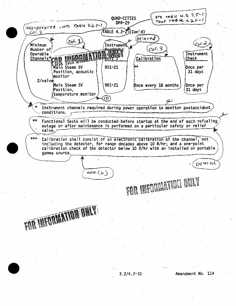
•
Minimum Number o~ _ .
g~:~~~~=~ni·-,ar•~ 10 . \li. IDJ \1\ U'tl . Main Steam SV
'\Position, acoustic · monitor · 2/valv~ ·
n Steam SV i ti on, ·
(Con'd) ~,,,__e .;_I e:-t~-?)
Ii" . .c~ Calibration
901-21
nee every 18 mpnths
1 Instrument \Check
.Once per 31 days
Once per 31 days
. perature monit6r
. ·~~---
I
\ :it Instrument channe 1 s. required during power operation to monitor postacci dent
~ .
"··-... cond_i_ti ons. r-'---..... -~--· . . . . . · . ~;~ti:~~~~:-.l~sfs·--~i11- be -condu-ct;d. bef ~ startup· at the end of each refue 1 i ngf .
outage or after maintenance is performed on a particular safety or relief ./ .--~ . - . . ·. --- .
xu Ca-l ib·~;ti-~~-~~fan e I ectromc ca 11 bratiO~~ including the detector, for range decades above 10 R/hr; and a one-point \ calibration check of the detector below 10 R/hr with an installed or portable) gamma source.r--~~~~~-..:.~~~~~~~_:_~~~--~~~~~~~---
t -~ \. ·~ c~~7bD
3.2/4.2~31 Amendment No. 114

•
•
~€l_.oLl4-\t::°-V CJ.D c W' TI4-B Le
I \ \ I \ l
o o ('.,. W\ P .e.r (.st- 'B~-ot
1~. a - ~ QUAD-CITIES ---------= '·
DPR-29
TABLE 4.2-3
RADIOACTIVE LIQUID EFFLUENT MONITORING INSTRUMENTATION SURVEILLANCE REQUIREMENTS
Instrument
Liquid Radwaste Effluent Gross Activity Monitor
Service Water Effluent Gross Activity Monitor
Liquid Radwaste Effluent, Flow Rate Monitor
Notes
[l] D = once per 24 hours M = once per 31 days Q = once per 92 days
Instrument Check [lJ
D
D
[4]
R = once per 18 months S = once per 6 months
[1][3] Functional Calibration Test [1J[2J
R Q [7].
R Q [7]
R NA
\ \
Source Check [1]
[6]
R
NA
[2] The Instrument Functional.Test shall also ~emonstrate that control room ·alarm annunciation occurs, if any of the following conditions exi$t, where app l icab 1 e.
.. a. Instrument indicates levels above the alarm setpoint. b. Circuit fai 1 ure. c. Instrument indicates a downscale failure. d. Instrument controls not set in OPERATE mode.
- 1- [3] Calibration shall include performance of a functional test.
[4] Instrument Check to verify flow during periods of .release.
[5] Calibration shall include performance of a source check.
[6] Source check shall consist of observing instrument response during a discharge.
[7] Functional test may be performed by using trip check and test circuitry associated with the monitor chassis .. - --··- ------ - -·-·---------------- --------------------
.. ,, \ \
/
Amendment No. 114
' ! i ! I

eCl-OL .. ~ . c;'i 99 -~ ~-IA-8.le 1~.~-'iJ ooc..m p~r:
~-~ QUAD-CITIES ~ /
I I
( I I \ I
I i
I , . I
\ I !
DPR-29 · ' . '- . . . . .
TABLE 4.2-4
RADIOACTIVE GASEOUS EFFLUENT MONITORING INSTRUMENTATION SURVEILLANCE REQUIREMENTS
InstrumeJtff\tifWIMif&V Main Chimney Noble Gas Activity Monitor
Main Chimney Sampler Flow Rate Monitor
Reactor Bldg~· Vent Sampler Flow Rate Monitor .
Main Chimney Flow Rate Monitor
Reactor Bldg Vent Activity Monitor
SJAE Activity Monitor .
Main Chimney Iodine and Particulate Sampler
Reactor Bldg. Vent Iodine and _Particulate· Sampler
Main Chimney High Range Noble Gas Monitor
Notes
[1] b = once per 24 hours M = once per 31 days Q = once per 92 days R = once per 18 months
B
B
B,.
B
B
A
B
B
B
[2] A = during SJAE operation B = at all times
D
D
D
0
D
D
. 0[5]
0[5]
0[5]
·calibra- Functional Source[l] tion[1][4] Test[1][3] Check
R .Q M
R Q[6] NA
R Q[6] NA '
.R Q NA
R Q Q
R Q R
NA NA NA
NA ·NA NA
R Q M
[3] The Instrument Functional Test shall also demonstrate that control room alarm annunciation occurs, if any of the following conditions exist, where applicable:
a. Instrument'indicates levels above the alar~ setpoint b. Circuit failure c. Instrument indicates a downscale failure d. Instrument controls not set in OPERATE mode --· -· -·--·· -
3.2/4.2~33 Amendment No. 114
\ I I
\ . \
l I
·1
i i
'
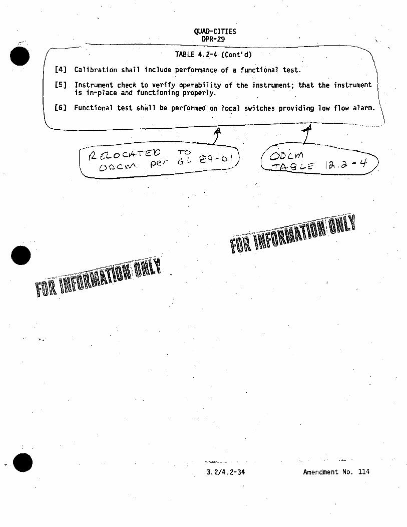
QUAD-CITIES DPR-29
• TABLE 4.2-4 (Cont'd)
[4] CalibratiOn shall include performance of a functiOnal test.
[5] Instrument check to verify operability of the instrument; that the instrument is in-place and functioning properly. ·
[6] Functional test shall be performed on local switches providing low flow alarm~
\ .
·-··· .... -··
-----,.
·:-i •.
3.2/4.2-34 Amendment No. 114

•
•
•·.
•
~ --' -· m :5 -c
f i l ~t E I "' ! ! ,. l t i
·:.. .':\
\\-~]1dtflfftll
· TEST INTERVAL (1 f hours
-·----------· -----
FIGURE 4.2~1
\ \ \ i I
' 1.
. ! i I· !
j 1' ;
!
- -- ---=-~·- ----· - - - - ._ -
TEST INTERVAL VS. SYSTEM UNAVAILABILITY
Amendment No. 114 .

APPLICABILITY: As shown
ACTION:
With less
.'•
.. · .. ····
\ ...
r . ~!.rore« 1P 0.P€ftA&LE Sf"Qru~ win./" 011e now,. or n.e At::rioAJ r~....,,,,,,~,od 6Y Tithle 3 ,a.A·/ /"
..f'ur "(h"'.,. ~r1p./'..,_l"C7~Vt Shall b~ nlkf'n, ·-------------~--- I ------··· - --~------------------ --· ------~---

•
. ~.
,··'
INSTRUMENTATION·.
4:1.Z:.3 e ISOLATION STEM RESPONSE T E of each isola. on trip func on shown in able 3.3.2- shall be demonst ated ·to be wi.th' its limit. at east once pe 18 months. ach test shall i elude at least e channel pe~ ~ip syste such that al channels are te ed·at least on ·every N·time 18 months, wher N is the tot 1. number of redun ant channe 1 s .. in a specific i so 1 at ion trip ystem.---------------~---~--~------~--------------------
GE..;STS (BWR/4) 3/4 3-10
\ ·.

ic;1 ,,, I
V1 ....... V1
....... CD E ;o ......... """' -
w ....... """' w I ~
~·
O"
R cloc.ic. t-eJ · -from ST'::> 1A°e,LE ~ .3.;;. • .. ~
· t o I u. v\ri v'1 ~ of'lot 3
1. PRIMARY CONTAINMENT· ISOLATION a. Reactor Vessel Water Level
·. :~ . ·~ . ~.
~. APPLICABLE ) 0a:n~~· ACTION·
·~· · ... 20
f: 2. ~SE~C~ON~D~AR~Y~C~O~NT~A~I~NM~E~NT~IS~O~LA~T~IO~N~-1r-----..:i~~--~----------~------------.__,.
a. 2 2 .
1,. 2, 3 · ~nd: .~ . i>2~ 3 ..
2 1, 2, 3 and·~.·
_\··.
. ,,,.

Ci1
r-:1· VI -+ . VI
w -~· w I
3.
: .
T-r,t · Ci) Ol'l!~e" $~ -SETfOI~,- tl) <>.~•· """j __:_~ -----. TA LE__l_~(Continued).
ISOLATION ACTUATION INSTRUMENTATION ~) ·~
VALVE ACTUA-~ ~ · ON GROUPS INIMUM APPLICABLE · . 0 RATED BY PEAA8l. CHANNE~~) OPERATIONAL Q,, . . S GNAL PER · SYSTEM fRPWll IWV-
2 1 ' 2, 3
2~ l ' 2, 3, ·-(d) .
ACTION
21 .
21
22
~ ~·
2f

•
e>::
"' I Vl -t . Vl
5.
e. Equipment Room · perature - High
f. RCIC P e Routing Area Tempera re - High
g~ RCIC Pipe outing Area A Temperatu e - High
,, _ h. RCIC Emergenc
FOR ~rij ~~r~Jrrmiru-~ L
j.
(1)
(1)
(1)
(1)
l)/(valve)
APPLICABLE OPERATIONAL
CONDITION
1, 2. 3
)., 2,.3.
. l~ 2, 3
l, 2,· .3
.l~ 2~ 3.
3
. 1, .
1, 2'
ACTION
23
23
... . ' .. ··,i-'!:· .
•• > •• ·, :
23
23
(25)
:·.··

•
"1 rn
I Vl -t Vl
5.
c. RCIC Turbine Exhaust. . Diaphragm Pressure - High
~s~~ ;; : (i:"RcIC"'iiqui PilfuAt Ro~ ..!. Temperature - Higli ~--... ~ --- '\: ' ' '
RCIC Equipm~nt Room " 6 Temperatur· - High
f. JC Pipe Routing Te perature - High
g. RCIC ipe Routing Area 6 Temp rature - High
h. RCIC Emer ncy Area Cooler Temperature - High
i.
j.
-----~------------
\ \ \ _«")
- '
•
AcnoN
tr. 1, 2, 3 23
~ 1 • 1, 2, 3 23
·cf I l 2, 3l I ya .@l@ 1, 2, 3 23
(1) 1, 2, 3
(1) ' 1, 2, 3 '
itf\1t1i-11 (1) I 2 I 3
(25)
--~·

RC"locQte
.(•c~ '5\S i~b\~ 3.~.cl ·d. ' ~olv..M~S ~ o.ll~ 3
(;} ,.,, I
V1 -i V1 '
-DJ ::c :;o
' ........ ~ -
.... ~· er
6. '
f.
h.
j.
ISOLATION ACTUATION INSTRUMENTATION
VALVE ACTU ~ ~. ~-----~' TION GROUPS ~IMUM
OP~~~~~~ BY PER .TRIP S~~~~=E~~)
2
APPLICABLE OPERATIONAL
CONDITION
1, 2, 3
1, 2~ 3
ACTION
23
23
'~)~··
HP.Cl. Equip ent Room A Telilperatur -.Hig~
HPC Pipe Routi Tempe ture - Hi
(
HPCI Pip Routin~ Area A Temperatur - High
-
~ .. :a. -o, .. ~C"Aer:i• ' :.,·~)fQ1:t~ • 2, 3
1, ·2, 3
.. 23
23 ~
\ '' ; ...
.. ".
23 '
(25)
··1:
', ' ';·. ~.~
;, ,, ... .,
"
: "

(~;i~~~~~ ~~~,~-~ - ~c;;~p ~:;:~, (i) (coll.A~"~' ~ llnd. ~
-~----------__..:___ __ __,./
Gl ,..., I
V) _. V)
~. _ ......... -- .
Rec..•< t ul4. TIO"
L-11\'(. W<A•e( lev"l\pe1 "',- .. .de "'H1~h
w • . _. U1
.C»
,I.
.---··--
c:r:~:,~·T, u•W. I lAf\ ;-;) ..... •.
~ ( I@b-. _----f-UN_-=c1:~I_O.~
7. a~ .Reactor Vessel~ Wte. ·
l~~el ~- Lowt-["evi1\3 . . « . x-s·j:v,. ' . · b, . .'- . · ·- 1 ~tn .g_...
Perm1551ve) ~·ssura .. ~"u:tm- · --..~ -'~-·~--.-~- -·· ....
. ···- .~··<1··--:. ....... , •. :t.~~ ...... ....__. ___ """\
c. ·· RHR E~pment rea ·
AH:::~~: High mperatu~;u~~h
.·~ e.
f.
(f.
2
~-
\
. (1) .
(l)/(group)
-· ·---··:-:--· -·· ----·--····------------- ------···-.·· . ..._ ___
- .. ',,,_., .. -···· t_.""?
1, 2. 3
(J--;-- /·J·· .. ./
. ..J_:_• · •· .... /~ .. 'I J(,el-'. , - I ' •• .., ·; ~ ~: :·~ .\t~.~--, · .. ·
. ·-- --- ----·--··· --- -----. - -- -
ACTlON

w' -~ w • .... U1
.Al
11. ,, .
'
• t
' II
a.
b.
HR·Area Coo .. r mperature -
e.
f.
- ...... ~<#·· --··~~ --. --~ /
(- /', . /·./ .. . ' .
{{ •....... //", ', __ ,, ~ . . ~ _,,., ~.. .
TABLE ~.§co4 il~"~f-1\Uill-
ACTION
1, 2. 3
3
(1) .. . 1,· 2, 3 . ·. 2!.
(1)/(group) 1, 2, 3 (25):'. .'• .
:• ----~·-----'-----·~
•: · .. . .,,.
, .

• \ ..
·.~.
. . ~ '
GE-STS (BWR/4) ·.·~t
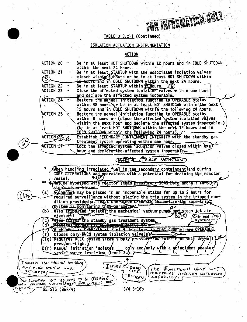
ACTION 20 -
ACTION 22 -ACTION 23 -
ACTION 24 -
CTION 25 -
*
**
TABLE 3.3.2~1 (Continued}
ISOLATION ACTUATION INSTRUMENTATION
ACTION
and in COLO SHUTDOWN
· t+ie. /:uN c. Tl 011a I (.,/,,.;; ('" _ ma111r"t:a{()S /So/aT1()1) o..cruaTJl-'11 "'-"'I' q b,; rry • ,__ ______ __,,

• I.r-lxll=\. - D~€"":> D~
r<; c-t P rn~ le... "3. ~. ~. - l ,,
- ..
(g) Normal background is as measured .during full· power operati~n ·without hydrogen being injected. With Unit 2 operating above 20% RATED THERMAL POWER and hydrogen being injected into the feedwater, this Unit 2·setting may be as.measured during full power operation. with hydrogen being injected.
(h) Includes a time delay of . 3 s t s 9 seconds.
(i) Reactor vessel water level settings are expressed in inches above the top of active fuel (which is 360 inches above vessel zero). · ·
-!i

-·-
~N~€)'2:f Q\A A-.0 c \rce.s ·:
n ""P ~L€ 3, a f A ... J \---
- - -_ -- ~ - -
. . - ·. . . ·----· -·--:.i'.=..-~.::......;..-~~-;;..:;.~-..:..i--.. ~~---~ ... ~ _: ........ ·-·-.·-··r·~.:-»... . -- - . - . (g) Only one trip system required in.OPERATIONAL MODE(s) 4 and 5 with RHR Shutdown Cooling
System integritY maintained. System integrity is maintaineQ proVided the- piping is intact and _ -.. no maintenance is being performed that has the pOteritial for draining the~ reactor vessel -
through the system. ~ _
(h) Normal background- is as measured during full power operation. without hydrogen be.ing injected. - --- -
(i) Includes-a time delay of 3 s t s 9 seconds.
(j) Reactor vessel water level settings_ are expressed i_n :inches above the top of active fuel (which is 360 inches above vessel zero).
(k) Also isolates the control room ventilati~n sySt:em. .a I

Cl ' m
I . Vl ' -t Vl
w ........ ~
w' I .... ..., CT
/. FOflNFORAtmf\\lll~~~
L ~·. ==========================="' TRIPs FUNCTION 1.· \ RIMARY CONTAINMENT ISOLATION
a·1 . Reactor Vesse 1 W er Leve 1
2.
3.
· \ 1. 1 ) Low., Leve 1 3 · · ·
) Low· low., Leve · \ . b. · rywel 1 Pressure - H h
· ~c. rywell and/or Suppre ·~ion hamber Radiation - Hig ·
d. · M nual Initiation e.
a.. · Reacto Vessel Water level -Low, Le el 3
b; · Drywe 11 es sure '.'" High c. Refuel Flo High Exhaust Duct
Radiation - igh d.
Refuel Floor Wal Exhaust Duct Radiation - Hig~
Unit 2 SGTS Actuati
g. Manual Initiation h. MAIN S EAM LINE ISOLATION
a. Rea~or Vessel Water Leve 1' Low Low 1 Leve 1 2
b. Main Si'eam line Radiation - High
d. Main Steam Lin
. TRIP SETPOINT U-) o'f'Psoen .
CJJ Q i.o,o cine~
.0 inches*. 38) inchesit
) psig
? (13.0) i hes>t
) inc~es
mR/hr.
c. Main Stea~mne Pressure - L
, ____ fJ~~lUgh _______________ --

C>: '" ' I I
VI -t' VI,
: ,·
',• . ;1 .
TABLE 3.3.2-2
y ISOLATION ACTUATION INSTRUMENTATION SETPOINTS ~---·-·-·-···----·------.__:__ ..
TR IP FUNCTIJON · . · · -----..
MAIN STEAM \1NE ISOLATION (Continu d)
e.
f.
'g.
h. i.
Co~denser Vacuum - Low
Hai\ Steam Line Tunnel Te~~erature - High · Hain\steam Une Tunnel A Teniperature -· High Manual Initiation
TRIP SETPOJNT(_l)
> inches Hg (absolute ·pressur ) (vacuum) ·
~ (99)°F NA
w 4. ~i
REACTOR WAT
w I ~ to C"
. ·~
5.
\
a·;
b. RWCS Are Temperatur~ - High c. RWCS/Area Ventilation A
Temperatu e - High d~ SLCS Initi tion e. · Reactor Ves el Water level
Low Low~ ~ vel 2 f. RWCS A Press e - High g; h.
~ (60) gpm · ~-(~47)°F or (11 3)°FI
~ (69)°F or (35.3)°F# NA
inches*
REACTOR CORE ISOLATI COOLING SYSTEM ISOLA ION a.
b. c.
RCIC Steam line a Pres.sure - High RCIC Steam S~pply essure - Low
~ (185 ) 11. H20
> (60) psig - ' I .RCIC Turbine Exhaust Diaphragm ,,/ Pressure - High \ ~ (10.0) psig .... ~·--·/ ~~--3-~-(-"-. ..,-,'f-~)"""/;.;__
--------·--~-----.:..·.>• .. ·----·-·- , ... -~.-·:.-•..Oo•••N·-·--··---·--·-·•••-'' ___ -••O '•• •••-0 0 ~ \'-l.~(uw\T~) ·
\l\C(..,p,, , • .,,~,. q._,«,
ALLOWABLE VALUE
. ' . < . 54)°F or 25.3)0
.
(80) gpm~
~ (78) .. or (44.3 Ft' :, .
.,,.
. "
e
. i

Cl m
I V'I ....... V'I '
; ..
w.: ........ ~
W· I ~. CD ,: er .
, .. '
..
\ \ I
.--·....-<>tw'-~11\f j.~ tfll . ~~ .. ~ -----··--- .. _ ff~ u ' -----.....
TABLE J.·3. 2-2 (Continued)
~ ISOLATION ACTUATION INSTRUMENTATION SETPOINTS -·---- --............. ·----
TRIP FUNCTION . - . . . .. · · ~.. cm~ SETPOJNl<.\)
HAIN STEAM LINE ISOLATION (Continued)\.::_____ ~ '. ~-··-·-:-r-::---·-·----·-
e. Condenser Vacuum~ Low !\ ~ (9.0)\ inches Hg (absolute 1 pressure) (vacuum) ·
f. Mai~ Steam line Tunnel \ · · \. Temp~rature - High \ ~ (177)0 .. ·
g. Hain\steam line Tunnel · · A. Temperature .. High · .. \ i (99)°F .
h. Manual, Initiation . \ · . NA
L . \ ·. . . . ·_.. \ .
4. REACTOR WATJR CLEANUP SYSTEM ISOLAT'ION
5.
a. RWCS A Rlow - High b. RWCS Are~Temperature - High c.. RWCS/Area Ventilation A
\ ~ (60) gpm \ · ~ (147)°F or (11 . 3)0 FI ..
d. e.
f. g. h.
Temp·eratu e - High SLCS Initiation Reactor Ves~el Water level -
low low, ~~vel 2 · RWCS A Press~re - High Manual Inttta ion
· ~ (69)°F or (35.3)°FI NA
inches* )psid
REACTOR CORE ISOLATI " COOLING SYSTEM-ISOLA ,JON \
a .. RCIC Steam Line ~ Pressure - High ~ (185)" H20
b . RCIC St,am Supply ~ssure - Low ~ (60) psig. . RCIC Turbine Exhaust Diaphragm ." c. /
Pressure - High ~ (10.0) psig -... ··
I
i
I i
.. I
ALLOWABLE VALUE·
I
.:1

C'> ' l'T1 I
~ TRIP FUNCTION Vl
,...... REACTOR CORE ISOLATION COOLING S OJ ~ ::0 ....... ..,. - d.
e.
\ f ..
' :g.
h.
i. j,
RCIC Equipment Room Temperature ~-High RCIC EqiJipment Room A Temperature - High RCIC Pipe Routing Area Temperature - High
. RCIC Pipe Routing Area A Temperature - High RCIC Emergency Area Cooler Temperature - High Manual Initiation
•
> - (
~ (89)°F
~ (167)°F11
~ (89)°F11
~ (147)°F NA
~ .. ..,. w . 6. HIGH PRESSURE-COOLANT JNjECTION SYSTEM ISOLATION I
~ . a. HPCI Steam Line flQw - High b.
c.
d.
e.·
f.
g.
h.
HPCI. Steam S~pply · Pressure ... Low ' · HPCI Turbine Exhaust Diaphragm Pressure - High HPCI Equipment Room Temperature - High HPCI Equipment Room A Temperature - High HPCI Emergency Area Cooler Temperature - Hfgh HPCI Pipe Routing Area Temperature - High HPCI Pipe Routing Area A Temperature - High
i~ Manual Initiation j.
. . ._ _ _..; ----------~- ........... _..___,.
> (110) psig · - . .
~ (10).psig - .
~ (167)°F
. ~ (89)°F
. i
I i I
I I '
300%' M fO..Tf1( Sr'10.<'V. fluv-.J(t)
·~l.al>.O 'c.11·1Q~j.
3Cl6':"4 l"" fO.Tt!'cl \. ~~~°'"' 'low(t-)\ ,Df'll~OE11) ,
I
\ \ i \ ...
~80~1ed,.. 3, ~.A- l
< - \
1 "lo ·c'°W:"o '- 1'T'1e~) ·
Qoo (o~el)< ----t
.; .

•
• • · F0fllfR'1l1f~~-~ _ ... ~·-~~---~
.---.~·----· TABLE 3.3.2-2 (Contrnued) "\
~ .-;~ . . . . . ISOLATION ACTUATION INSTRUMENTATION SETPOINT~.) -t •. .,.,. ' •"·" .... --- ... '""·--.--"~~··- ..... VI
w ~ w
I N 0 CT
a. React r Vessel Water Low. l vel 3
· b. . Reactor essel (RHR Cut-. Permissi. ) Pressure ~ Hi
c. RHR Equipm t Area A Temperatu - High .
d. RHR Area~ool r Temperature -
e~
f.
g.
High . .
~~
. (l) bQe~oe n ·TRIP SETPOINT c.f'l Q1..o\o c.anet.
~ (167} F~
( ) NA
. . . . . . . . . . . . . . . :
' ... ......_, ________ . __ _._.._ __ ,. ___ _,_,,, _ _..._~"'•-............. ,.:......,,.,,., ·--~"•r.-~ ....... _ ........... -._:~~~ .... .,,..-·.,.. ....... -.--.,,..---.. . .-~-. . _ ____....,._,. ___ --.---~
••••
·-~ , *See Bues Figure 8 3/4 3-1. . . . . , , . ...Yu it I a 1 se tpo I 11 t. fi-na t-setpo1 nt-to be-f;le term t ned ·· dur fog-9ta rt.up..J.es 4..-ro:...glflfl'fll.iffilii,-.lrAnmy:;-";;r:oieqmunt,.rined1-rcmha'"n'*'~le
to-thi"S"'"S'ftlio int sha 111>1!-subm·Hrted-to-t-hriomm·issloo-wi thi n-90-days-ot-test-complet-ilJTf.' · #Lower setpotnts for TSH~G3S-N600 E. F and TSH-G33-N602 E, F. .
1115 minute time delay.
~·
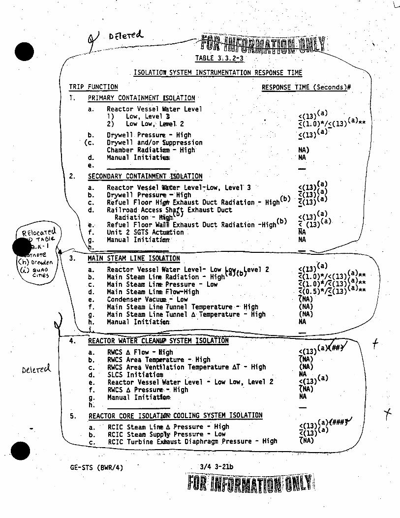
•
--·
_t .. -~~~ .nmu~wm~m -:-..-···· . TABLE J; 3. 2-3 .
. ISOLATIOll SYSTEM INSTRUMENTATION RES.PONSE TIME
TRIP FUNCTION
l. PRIMARY CONTAINMENT ISOLATION
a. Reactor Vesse 1 Vla.ter Leve 1 1 ) Low, Leve 1 31 2) Low Low , · Ler.e l 2
b. Drywell. Pressure: - High · (c. Drywell and/or S'appression
Chamber Radiatimi - High d. Manual Initiatia e.
..
2. SECONDARY CONTAINMENT -lSDl.ATION
. .
. RESPONSE TIME (Se~onds)#.
<(13)(a) · <c1~0)*/<Cl3)(a)** ~(13)(af'
NA) NA
a. b. c. d.
Reactor Ve~se.1 ia"tter Level~Low, Level 3. ·. <(13)(a} Drywell Pressun! -·High ~ . . . · ((13}(a) Refuel Floor His.ft' EXhaust Duct Radiation.- High(b} · ~(13}(a} Rai 1 r~ad. Access~ Sht6) Exhaust Duct <(l3)(a)
Rad1at1on - IHg,h. . · (b) ( ) Refuel Floor WaTill Exhaust Duct Radiation -High < (13) a · Unit 2 SGTS Ac:tm:tion ·. . ·· . · 'RA Manual Iriitiatfm. NA
MAIN STEAM LINE ISOIAIION
,.
a. b. c. d.
· Reactor Vessel Water Level- Low ti,(b~evel 2 Ma.in Steam Line. Radiation - High Main Steam LirE Pressure - Low · Main Steam Lire How-High
<(13)~a} ~ <(l.0}*/<(13)(a)** ·) · <c1.0>*1<c13)Ca)**
. <co. 5)*/<(13) (a)** 1 Condenser Vacum ~ Low e.
f. g. h.
Main Steam Line Tunnel Temperature -· High Main Steam Line Tunnel !J.· Temperature - High Manual Initiatian· · ··
4. ·REACTOR WATE CLEANIP SYSTEM ISOLATION
a. RWCS tJ. Fl ow - B.igh . . b. RWCS Area Teinperature - High c. RWCS Area Ventilation Temperature AT - High d. SLCS InitiatiOD .. e. Reactor Vessel Water Level - Low Low, Level 2 f. RWCS A PressuNJ. - High g. Manual InitiatiQn: h.
5. REACTOR CORE ISOLATidl'N: COOLING SYSTEM ISOLATION
a. RCIC Steam Line A Pressure - High b. RCIC Steam Supply Pressure - Low c. RCIC Turbine Exbaust Diaphragm Pressure - High
GE-STS (BWR/4) .. 3/4 3-2lb
tNA) -(NA) (NA) NA
<(13)(a tNA} · (NA) NA . <(13)(a) tNA} NA
. <(13)(a){###J1 ((13)(a) °f NA)
fUlifORMATllif011
f ·
f

•
•
·-
TABLE 3.3.2~3 (Continued) . . ISOLATION SYSTEM INSTRUMENTATION RESPONSE TIME
TRIP FUNC RESPONSE TIME (Seconds)#
REACTOR SYSTEM ISOLATIO d. RC C Equipment Room Temperature - High· e. RC! ·Equipment Room ll Temperature ~ Hig f. RCIC ·~~pe Routing Area Temperature - Hig · · g. RCIC ~pe Routing Area ll Temperature_ - Hi gn. · ._ h. RCIC Em~rgency Area Cooler Temperature - Hi\ h · }: Manual _f~-tiati~n . _ .. _· ·_ : ·.
(NA) (NA) (NA) (NA) (NA)
NA
..
6. HIGH PRESSURE ·c.OoLANT INJECTION SYSTEM ISOLATION . a. HPCI Steam ow - High .
b. HPCI Steam Sup ly Pressure - Low . ·
<(13)(a)(####f -(13)(a) · . ( ) c. HPCI Turbine Ex ust Diaphragm Pressure - High
· d. HPCI Equipment R m Temperature - _High . e. HPCI Equip~ent Ro t;,. T~rature - High· f. HPCI Emergency Area ~ooler Temperature - High g. HPCI Pipe Routing Area Temperature - High · h. HPCI Pipe Routing Area\~Temperature - High 1. Manual Initiation . _J,_ · · . ;~R SYSTEM SHUTDOWN CO~LING MODE ISOLATION
(N (NA) (NA) (NA) (NA)
NA
~(13)(a) Reactor Vess.el Water_ Level - ·"ow, Level 3 Reactor Vessel (RHR Cut-in Pemissive) ·
Pressure - High . · · \ (NA) · RHR Equipment Area t;,. Temperature\ High· (NA)
e. ~RHR Flow - High . (NA) f. nual Initiation NA g. . . .
•
\
RHR Area Cooler Temperature - High\\ (NA) .
(a) lsolatio" system instrumentation response time, specified includes diesel gen~ra:or tarting and sequence loading delays~\ · .
(b) Radiation d :tectors are exempt from response t.ime,. testing. Response time sha 11 be. mea red from detector output or the .i npu~f the firs~
. electronic co anent fo the channel. · · · · .
*Isolation syst instrumentation response.time for M 1Vs only. No diesel generator delays ssumed for ( ) valves. _
**Isolation system f trumentatian response time for assoc ·-ated valves • except MS IVs. · ·_ .· · _ . . . \_
#Isolation system instr entation. response time-specified for\the Trip Function actuating each alve group shall be added to isolati~n time shown in Table 3.6.3-1 an 3~6.5.2-1 for valves in each valve.group to
I ·obtain ISOLATION SYSTEM RE ONSE TIME for each valve.
'&/#With time delay of (45) sei:o s.r · ·
\###With time delay of 13 + 0, -1) econds. ( · ·
\##~#With time ctelay of .
"-----· -----..:..._~-----=~--------:----- --GE-STS (BWR/4) 3/4 3-22b
,_
\ ·.
i I If L
\ '(
-~'
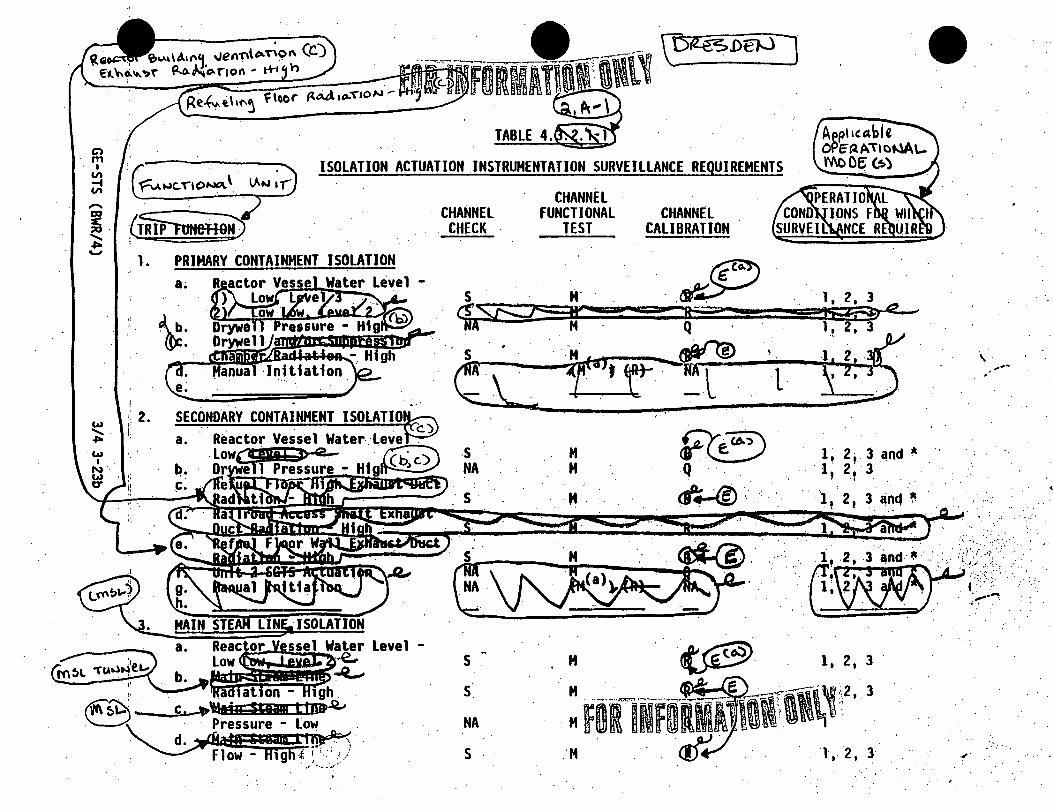
Cl ,,, I.
VI .... VI
· <Ttift1He119!} 1.
a.
~:
' 2. lAJ I
"'-· I .,,.
. ~"'''
TABLE 4.
ISOLATION ACTUATION INSTRUMENTATION SURVEILLANCE REQUIREMENTS
· CHANNEL CHECK
s s
NA
s .
CHANNEL FUNCTIONAL
TEST
M
.·M.
CHANNEL CALIBRATION .
••
1, 2, 3
l ,. 2, l
\ . ... -,
.. . ·:··.
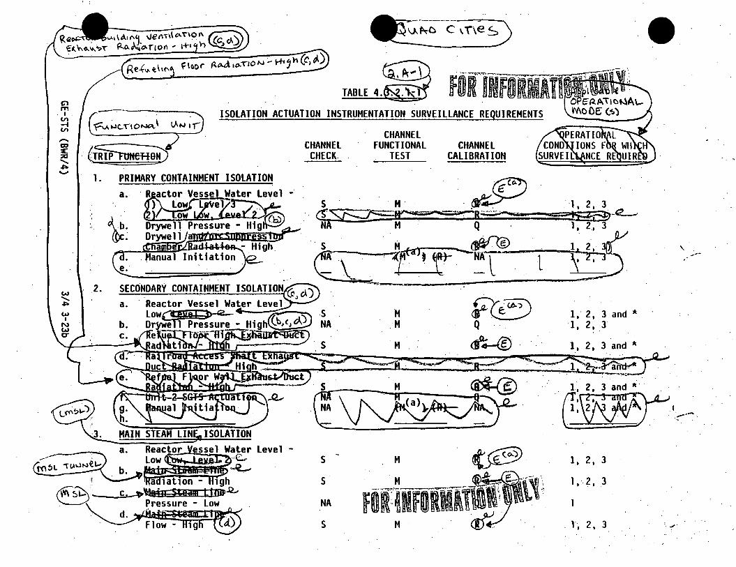
Cl ITI
I . VI -i VI
' 1'
1.
a ..
2.
FOiflifllRMAYllJf-c--. 0 c;-~A"ttct-lA\.-
TABLE 4.
ISOLATION ACTUATION INSTRUMENTATION SURVEILLANCE REQUIREMENTS Mc Cc(.~)
· CHANNEL CHECK.
s NA
CHANNEL FUNCTIONAL
TEST
M M
M
CHANNEL CALIBRATION
FCB Q . .·
~..-®'
l
.· ·1. 2. 3 159i'3f)-e._, . 1. 2 .• 3
~2, y ; 2, ~) .. > ..
1 . • 2. 3 and *
·1. 2. 3
3 and *
1. 2. 3
. l, 2. 3
' ---
I ~-~---.
. .I'

Cl m I
~ VI
w ...... ... w I
N.
t
CHANNEL CHECK
NA · HA
·CHANNEL FUNCTIONAL CHANNEL
TEST CALIBRATION
.~S M
.. ,
., " .. ·
/'·
.-
.;(
. .,,.

Cl m I
Vl ~ Vl
w ...... .,,. w
I N· .,,. er
.5.
CHANNEL CHECK
NA
·CHANNEL FUNCTIONAL
TEST CHANNEL
CALIBRATION
Q
~·
.J
1,, 3"" ~ 1~2,,,. .
1 I 2, 3
l I 2, 3 . .,, ..

•• FOR:l~flRfatWf~ll\, Q., ~,,.I
....__ ...... Y C> ,,,
I V'I ~ V'I
w ....... ~·
w I
N U1• C'
6.
f.
g.
h.
i.
TABLE 4. - (Continued) ISOLATION ACTUATION INSTRUMENTATION SURVEILLANCE REQUIREMENTS
1c· Equipment Room 6 mperature - High RCIC Tempera e - High RCIC Pipe ting Area . 6Temperature RCIC Emergency Ar Temperature - High Manual Initiation
CHANNEL CHECK
ISOLATION
CHANNEL FUNCTIONAL
TEST
M
M
H
M
CHANNEL CALIBRATION
Q
Q
Q
NA
1 •
. 1. 2. 3
1. 2, 3
2, 3
. 2, 3
.e.--~· __.,,..,.___.,'IO"'l...-r".Eq:-::u:i'"i p~m::-:e~na:-t riRi:'oo:::":m:-------~ . ..,...A ____ ,.~ ... ," · · • !.:.~ '-3
. ;.:~~:;;:;;~:~~~!- Hlg : HM--~- ·- • :Q- .. · .· ~ ....... ·· . .· :: :1 . HPCl P Routing Area .. ~ '
3
~ Temperatur High ~1. 2, .3 ·
. ·: : . . ".,,. . ~. : ' '··(
, .

I
• )_:0~~ ONI-'/] · .• \ .
CHANNEL CHANNEL FUNCTIONAL CHANNEL
CHECK TEST CALIBRATION
:=:===P~R~E=ss=u==RE:_CO-O-LA_N_T_I""~-;J-C_T..:..10-N--S-Y-ST_E_H_l.:S=OLA~J=IO=-N~("."""C..;.on-=inued)-~-~-• ..........,.....___~..:_,.,....:... -
w ....... .... w I
N
g! " I
' 1 •• ,,
Rec1rc v. \o.ipof\ j..1 f\e iJJ A:r11e .r rev-Ape" ":ru re
!1
. ..~
Q NA
,.
1, 2, 3
. /'
. ( . .-
\

• . FOflNFOflJJ\[f \\l\l, C> ,,.,
I ~ --f ~
w ....... ~
w I
~· CT
TABLE 4. (Continued) ISOLATION ACTUATION INSTRUMENTATION SURVEILLANCE· REQUIREMENTS
PCI Pipe Routing ea . . A~mperature - High
i ... Man~~itiation· J.
NA NA
. .
' 7. RHR SHUTDOWN COOLING MODE ISOLATION .:..:.:..;.;~.:=:::;~~;..;;..;..;;;..;;..;.;;.;..;_=.;;;-=.;~.;..;.;;.;~~;;..;;;;.;~;;.;.;
a.
b.
~· f. g.
s
NA
NA
H
H r
M
CHANNEL CALIBRATION
Q
NA
Q
./'
l, 2, 3
.·.' .,. ; ..
. ;:~. . •, ·.: '· . ~ '
. •.·.··· (.: ..... ,, ..
. ....... . . . ..~.

- -
e;t::: ~:.::=:~ :;7: ~·· 31 ~;¥. ;; .. ~&m1tto·• : .. ""'!; • .:;:~ .. (b) This function is not required to be OPER. . . -- - - . _- - . .
not required. _ -· __ ABLE when PR_IMARY CONTAINMENT INTEGRITY is - ,-_· ,:, (c) Isolates the reactor building ventilation system a d ... _-, -.·. . - - - . . I I · · _ n actuates the standby gas treatment system. \
1~ QO ----~5
(b) This function is not required to. be OPERABLE when PRIMARY CONTAINMENT INTEGRITY is
not required. · · · ·
(c) Isolates the reactor building ventilation system and aC:tuates the standby gas treatment· . . . .
system.
(d) · Also isolates the control room ventilation syStem.
'----...;__;__~....,.._;.._~_;.,~-----~---------------~---~-----------------~~--:-~-___,.
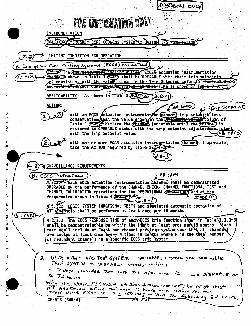
,, . ·_. [b~elj °"q] ... ''·
• FOi']NfORIATldf\\~ll! ....... · · · . .·.
\ · .
r
1
~:
LIMITING CONDITION FOR OPERATION
ACTION:
~
With one or more ECCS actuation instrum ntation c anne s inoperable, take the "ACTION requir~d by Table- 3,..._,.,
~ SURVEILLANCE. REQUIREMENTS
a. cCC.S A~"flAD.·f'to~ · . · . . · · · _· ~·~l tit.PS
ach ECCS actuation instrumentation-<ai&iiiiiJ) shall be demonstrated OPERABLE by the performance of .the CHANNEL CHECX 1 CHANNEL FUN T ONAL TEST and CHANNEL CALIBRATION operations for the OPERATIONAL and at t e
.. frequencies shown in Table 4.~-~, 9 ,, D . . .· . t> E '~~ .·
~ LOGIC SYSTEM FUNCTIONAL TESTS and simulated automatic operation of . ~n~s- shall be performed at least once.· per .18 months. . . @lcA~ · . . . .. · ...
. 3.3 The· ECCS R PONSE TIME of each CCS trip function s in Table .3.3-3 shal be demonstrated be within the 1 it at least once pe 18 months~ .. ach test all include at st one channel pe trip· system such th all channe are tes d at least once ery N times 18 mo hs where N is the 1 number of redun nt channels in a ecific ECCS tri stem.

TABLE 3.
·EMERGENCY CORE COOLING SYST~CTUATION INSTRUMENTATION
· . s . Ml~~~~:~~:~ APPLICABLE . TRIP (a,) OPERATION ~ FUNCTION .
1. CORE . SPRAY SYSTEM . . . @ . ' i · . a. Reactor Vesse 1 Water Le~~ow lo:c[~K-]) b. Drywell Pressure - Hig .... ~ . • c. Reactor Vessel Pressure - Low (Permissive)
~· 2
. cs~~m Discharge Flow - Low (Bypass) nu n at o
2. ·.··LOW PRESSURE COOLANT INJECTION '8(>BQiF RHR $~~) S'-'66-r~~e m)
a. Reactor Vessel Water Le~Low Lowt?'iiil:jijeNt" ~ b. Drywell Pressure - High• <.ff); . · . · - ~~ .. c. Reactor Vessel Pressure - Low·(Perm1ss1ve) 2 ·
.. ' !!
. c~.~~~~~-[!~-\La.w-18-~~~~~ 3. HIGH PRESSURE COOLANT JNJECT~SYSTEr--@ ----
a. Reactor Vess~ Water Ley~- r(:w Low~ 4 b. Orywel 1 Pressure - Hig~ ~ 42~ c. Condensate Stora e Tank Level - L~~ . ~ d. Su press fon ater Leve 1 - -Hio,,.~~~ ~ . ;. e. eac or es el Water Level - High~ ~.-__........,. ·-f. HPCI Pump Discharge Flow - Low (Bypass) ~ ~ ~l . cb-:-~~~~~-~--!~!_!!_C!ti~!l~ ) ~!~/(system)
--:____ . ·:-::=;~ . ~. ·-_Q~
FORlNFUlllff(i\1
1. 2. 3 1. 2. 3 1. 2·. 3 1. 2. 3 1 2. 3 • 1. 2. 3. 1. 2. 3 .. ,~ ~-
· ACTION
30 30 31 32 . 33
35
~· ~· 31 33 34 .
----:r ' . .4'.

Cl
'" I Vl -4 VI
TRIP FUN4TION.
4.
w ~;
:~. I , b:
N ti • \0 . .. \e
~I. LOSS OF POWER
1. 4. 16 kv Emergency Bus Undervol tage (loss of Voltage)
2. 4. 16 kv Emergency Bus Under___ -zv:..:::ol tage (Degraded Voltage) \\ t .. f~
1/bus
3/bus
.. ·~~.
FOR-INf ORMATllfflll • ACTUATION INSTRUMENTATION
MINIMUM O~a..CHANNE~
TRIP . . FUNCTION(a)
I'
1. 2. 2 •. 2. 2.
3 3 3 3
ACTION
30 30. 31 31
--~-·
: .. ~,-. _.::_ .. :·. . . .
. ' . r( . -·~
.. n:.'
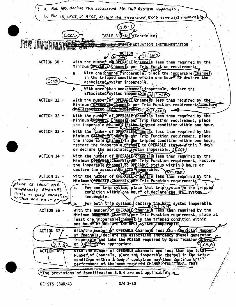
' a.. FD<?.. ADSJ d.ulore "?he Q..ssoc·1ared ADS ~P sysTirM 111ope<tible. .... . . ' . .
b. For- '-S L-Pc.r or ,..Per declare 11ie. il..S5oc.1~re" e:c.~~ J· I I -~
ACTUATION INSTRUMENTATION
ACTION. 30 -
Ecc:.!1 -.b.
ACTION. 31 -
ACTION 32 - .·
ACTION 33 -
ACTION 34 -
ACTION 35 -
ACTION 36 -
proviSions"of SpecificatiOn 3.0.4 are
GE-STS (BWR/4) 3/4 3-30.
'·
/. /: l·
,(· ,f
.k
j·~· .
.
{ it
/'f·

I~
3 3 3 3
.30 30 31 31
~!::~~~~s===~~=rnm~~~~~~~~::-~ --- --:_---"'."""---~-:-----~-----------------~---~··..;.. ........... -·..,.•' .. "-0..:.·n>·Att ____ ..,..---:-...._
d~ · l.o~ a...ow Le\Je.l ,-,·W'er-. ·· \ a 3 · ) I
.\ .
.(f) . This function I• not required to be OPERABLE when PRIMARY CONTAINMENT INTEGRITY is. > not required.
(g) With rio LOCA signal present, there Is an additional time -delay of 5 :t: 0.25 minutes.·
(h) Reactor water level settings are expressed in Inches above the top of active fuel (which is 360 inches above vessel zero).
~· fi\ em . I iQA 11 •1 19t11M19 81!19til7 •l'?!H s §llljjO,
.. :"~· , (j) There is· an inherent· time delay of. 7 ± 1.4 seconds on degraded voltage. ,.··•"
-r." ..........
···-·-- .. :-.--.__..:___~_ ... , .
. . :.

Ci1 ,..., I
Vl . _. Vl
w ....... .,,. w I w ....
'.
TRIP FUNCTION .
1. CORE SPRAY SYSTEM
a. Reactor Vessel Water Level Low Low Low, Level b. Drywell Pressure - High c. Reactor Vessel Pressure·- Low d. CSS Pump Discharge Flow - Low e. Manual. Initiation f.
2. LOW PRESSURE COOLANT INJECTION MOOE OF RHR SYSTEM
a; b. c .
Reactor Vesse 1 Water .Leve 1 - low Low LQw, Leve 1 . · ·orYwell Pressure - High · . · Reactor Vesse 1 Pressure - . low
d. e.
LPCI Pump Discharge Flow -Low Manual Initiation . .. .
f .
: 3. HIGH PRESSURE COOLANT INJECTION SYSTEM
a. Reactor Vessel Water Level - (Low Low. Level 2) b. Orywell Pressure - Hfgh · c. Condensate Storage Tank Level - Low d. Suppression Pool Water Level - High e. . Reactor Vessel Water Level - High, Level 8 f. HPCI Pump Discharge Flow - Low g. Manual Initiation h.
.. ;._·.:.·: . . : ·:····.····
>-(38) inches < (1.69) psig > (x+J) inches < (Y-3) inche <- (54) inches > ( ) gpm RA

C> rp "' -t
"'
w
' .,.. w I .
w ....,
• TRIP FUNCTION 4. .AUTOMATIC DEPRESSURIZATION SYSTEM
a. ·Reactor Water level - Low Low Low~ Level 1 b. Drywell Pressure - High c. . ADS Timer . ·
. d ... Core Spray Pump Discharge Pressure - High
e. RHR LPCI Kode Pump Discharge Pressure-High ·,
f. Reactor Vessel Water Level-Low. Level 3 g. ·· .. Manual Initiation h.
5. LOSS OF POWER
a. . 4.1~ kv Emergency Bus Undervoltage (Loss of Voltage (**)) ·
. fOR1ifORMAtlfifl\\\l~ b. · 4. 16 kv Emergency ·Bus Undervoltage
(Degraded Voltage)
. ~ (14
· ~~16 kv Basis - .· (2940)+(16l) volts
b. 120 v Basis - · • 84)+(4.6) volts.
c. < (lD) sec. tfme - lay ·
a. 4.1 kv Basis~ (372 )+(9) volts
b. 120 Basis -(106. )+(0.25) volts
c. (10)+(0~5) sec. time delay
. ~e,\e 3, ~. '3 .... 1 c_c\ u o/"(\ f' 'd- ·
........ · . . .,,.

• '·· .
(;.- ··-LOS~ OF P~WER. \ \
. I a. 4.1S·t<v Emergency Bu~Undervoltage . 2930±146volts (Loss 'of Voltage) . \ . · . · .· . decre·a~ing voltag~
b. 4.16 k~-ergencv Bus Undervoltag ~· 3784 volts (Unit 211
111111
(Degra~ed\voltage) \ ~ 3832 volts (Unit 3)1
111111 \ . ' ..
"'
I \
rdss.oF.-PowE __ . . Trip setpoiot
• 16 v Emerg~ncy Bu~~nde · ;\ · oss o Voltage;\ . . . ·\ · rvo tage) 3045~152 volts
. ' . . de~m~~~ ti 4. 16 kv Efl\ergency Bus U d . . . .
(Degraded Vo.ltaget · - 0 ervoltag Ci: 3845 volts (Unit 1)'111 ID ·\
, , ·. • , l:'3833 volts (Unit~~·
\ \ .. --- -- -· - --- ~- ·--
·---·-·---···- . ·----------------'"---

ECCS.
1.
z.
3.
4. · HIGH PRESSURE COOLANT;.INJECTIO
5. . LOSS OF POWER
GE-STS (BWR/4) 3/4 3-33
NA
~ (30)
NA· .
. '·.
Seconds

Cl m . I
. "' . ... "'
w ...... ... w I
w ...
2. LOW PRESSURE COOLANT INJECTION
3.
CHANNEL CHECK
CHANNEL FUNClJONAL
TEST CHANNEL
· CALIBRATION
1. 2. 3 l. 2. 3
1. 2. 3
i. 2. 3
Pifplicable OPEYt-A\I otJA L t'\'\OOc Cs)
, .

Cl m
I
e . FOf INFDRIAtlfUl'f
"' -t EMERGENCY CORE COOLING SYSTEM ACTUATION. INSTRUMENTATION SURVEILLANCE REQUIREMENTS "'
~~ 4. 16 kv Emergency Bus Under-. '(~ltage (Loss of Voltage) NA
b. 4. 16 kv Emergency Bus.Under-
~ voltage (Degraded Voltage) .
ldl Thia, function la not required to be OPERABLE when PRIMARY CONTAINMENT INTEGRITY. : requ~red. · · · .11 not
lel Trip units are calibrilted lit least once per 31 d. ·· · . . . ... . . , , avs and transmtttP.rs arP. r-~liJ-,r-~tP.rf ':'It th~ fr~r,,,. .... ,,. ..
CHANNEL FUNCTIONAL · TEST
'. ;. ~ .. -.
CHANNEL ·CALIBRATION
. 1. 2~ 3 1. 2. 3 1 • 2. 3
· 1 • 2~ 3~
.1 • 2. 3,
4
.4Vs • ...
......

fOR'"lrlfODUmtflflt1 Q14. 3.; ~=e UeHtATISll PUMP :rA Ip AHHAT;~STRUME.NT~TION
,.
@ ATh'S
@-t> LIMITING CONDITION FOR OPERATION
Trip
inoperab nne include two reactor vessel water level .....-~~4~Effilniiiei1s or two reactor vessel pressure \r:nanneTu, declare the
s s em inoperable."
system7 within
. . · a.. · . - RPT' . . · . JI.ti . . ~~- 3. 4.1. TT Each A'T\IS bC'rit1la\uB ?'@" I ·u nst§IP instrumentation chan e
\.:..!) shall be demonstrated OPERABLE by the performance of the CHANNEL CHECK, ·CHANNEL ·. FUNCTIONAL l:EST and CHANNEL CALIBRATION operations at the frequencies shown in
... Table4~~ ·· · . . .
~LOGIC SYSTEM FUNCTIONAL TESTS·and simulated automatic operation of ·-· · --al l~@ianne)s- shall -be performed at. least once- per 18 .months. . "
~ .
GE-.STS (BWR/4) 3/4 3:-36a

• C'I fT1 I
V\ -f
"'
w
' .,,. w I
w ...... r:u
l.
2.
. • . _ •
.·l.)i-lli
a,t-1 .~.J2.., . ~· TABLE 3. .
S'ISlEMhNSTRUMENTATION . . . . .
-= · MINIMUM ~tfANNELS
-~fl.
ATWS ~bTl9H liQtfp IHIP
Reattor Ve~sel Water level - . low lowct#•el !]-e-
Reactor Vessel Pressure - .High . ..
..
. TRIP SYSTEM(a)
. Cb) ~ '84 ,,, c.he!7 · · - . . .
---···-------~-~fillflfRJ11W1110111~ .. "f\t"t't.. O.c..lo.y a.f .e ~ 1: ~ 10 :sec.onch. · ·L_; _________ .....,...~~
..
PER .
. .... I
.. •I
I.
status f~r up lo 2 hours for tcquired surveillance.
•• ' .

C') rn I
Vl -i Vl
w ~ w
I w (X) QI
ffilfllrDRll1-l\,~. -------::::..-----~~~--~~~---~~------·---------- ---- TABLE 3.3.4.1-2
ATWS RECIRCULATION PUM TRir SYSTEM· INSTRUME TATION SETPOINTS
L Reactor Vessel, Wa r Level ... low low, level 2
2 •. Pressu \:Ugh
..
\ ~•see Bases Figure 83/4 3-1.
TRIP . SETPOINT
~ .. (38) inches~ .,,
1 (1135) psig
.·
, .... c...orporo...TeJ · ltJlo
IV\- e, L-€ 3. ;;l,. c. - I . . c.o L- v... ""' " a ;) .
•• ·'~
. .... I
' . '
I.
~·

C'> ,,, I
. V\· -f V\
w ....... ~
w I
w
'° Ill
~-.• -R.-;ilNIRMll\ll~!~l~~
CHANNEL FUNCTIONAL CHANNEL . .TRIP FUNCTION
CHANNEL CHECK. TEST . CALIBRATION
~.
2.
Reactor V~r level _Low low~
Reactor Vessel Pressure - High
S.
·~ H -~-
.H ::,·~
.
~er 31 cJ..o.ys 4.t'lt/...·
t . . · ...... 11 ~ ro.-ecl a:r ,_leo.~'f' onc.e ,- .
.
Trr1p o.nin c::tre. · ~... ' --'e. ~ .. ,JJ ,.. . Q.T" th..e -frft;_iAff'ICf IM- ~Tl'rl..-. «
. ;ra.,-,!.m i'ffers 4re co.l1bra. ret4 (,) ,~ (he -ro.blf. ----__.:~---:-----~-----------
. .
.I
i
• . I.
" .-
' . .,,.
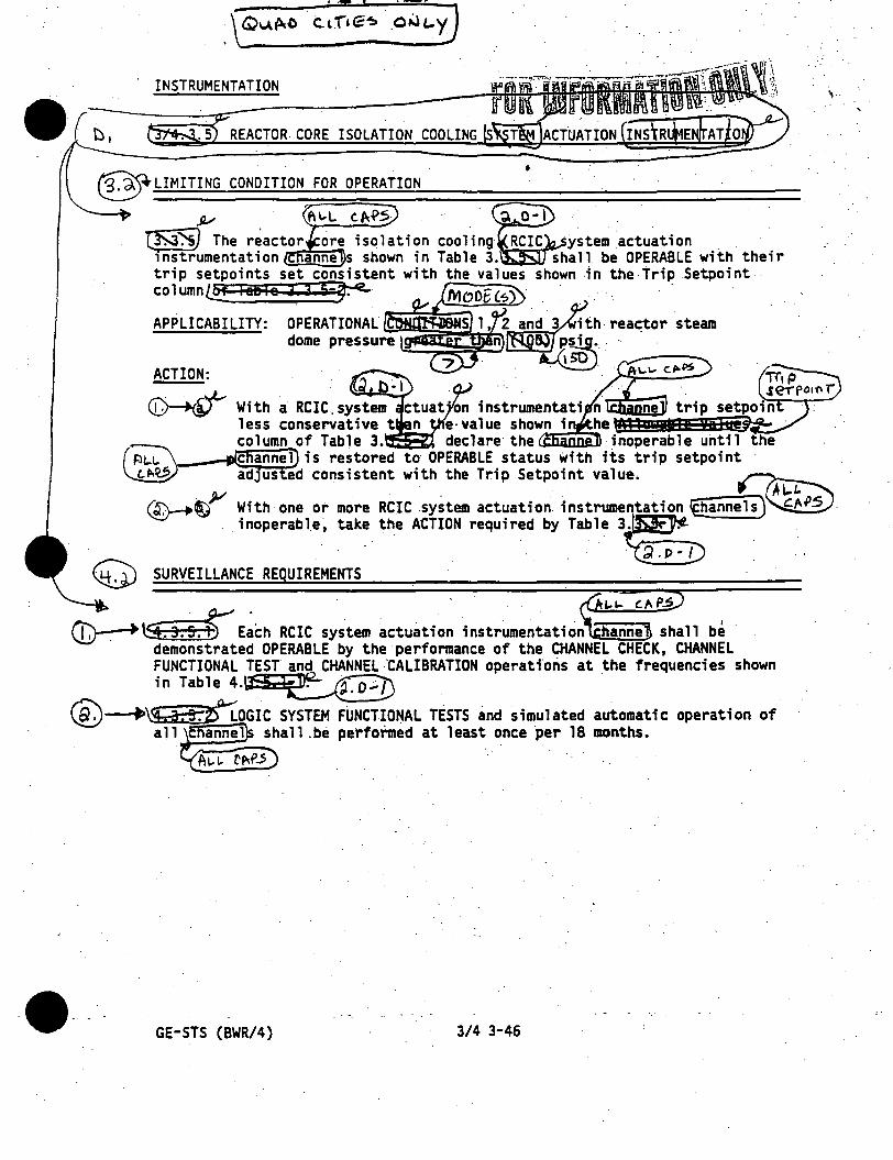
.. - t • .-1-
INSTRUMENTATION
REACTOR- CORE ISOLATION COOLING S
@LIMITING CONDITION FOR OPERATION -
,µ
•
-@-."""'~ ...... -i The r~actor ore isolation cooling RCIC ystem actuation _ _ instrumentation anne s shown in Table 3. shall be OPERABLE with their trip setpoints set conshtent with the values shown in the Trip .Setpoint-column@ laSle 3 3 5-~ _ MoDEl$ · _ _ _ : · - -
ACTION: ~ :. I
~ With a RCIC. system ctuat ·on instrumentati n ~SifSSB~iii~ less conservative t n e·_value shown i he 1 column of Table 3. declare the inoperable until the
,_
(~ .....,tcnannel) is restored to OPERABLE status with its trip setpoint · ~ _ y adjusted consistent with. the Trip Setpoint value. _ ~
~~ With -one or more RCIC ,system actuation _instrumentation ~annels)~inoperable; takl!. the ACTION required by .Table 3~
~ SURVEILLANCE REQUIREMENTS -
. t..i.. (../\PS
(C)-->\S.3.s.t' E~ch RCIC system actuation instrumentation hanne shall be· demonstrated OPERABLE by the performance of the CHANNEL CHECK, CHANNEL FUNCTIONAL TEST and CHANNEL "CALIBRATION operations at the frequencies shown in Table 4.~ _ _
@-+~25°LOGIC SYSTEM FUNCT~ONAL TESTS and simulated automatic operation of all annel shall .be performed at least once per 18 months.
CM'.5
-·-- GE-STS (BWR/4) 3/4 3-46
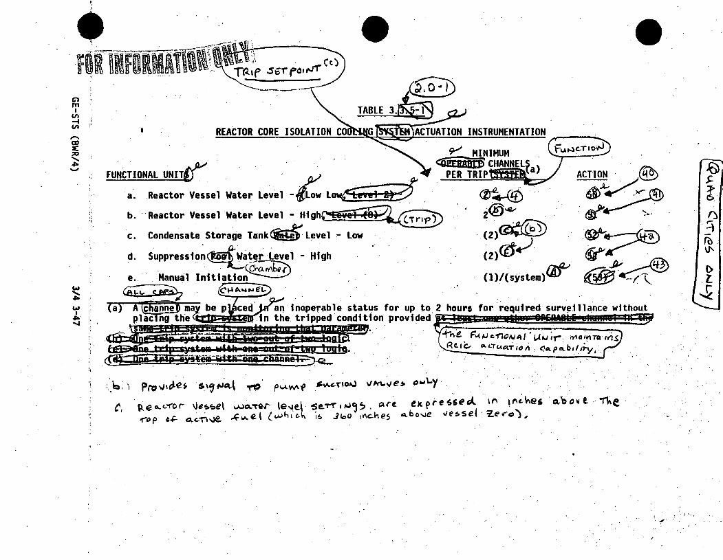
Cl "
"' I VI ..... VI I REACTOR CORE ISOLATION CO ACTUATION INSTRUMENTATION
FUNCTIONAL UNIT~ _?" ·~ a. .Reactor Vessel Water Level -flow Low6'!ve1 1ti'
.¥ MINIMUM <:iiiifRJUltiS CHANNELS ).
PER TRIP {a
b. Reactor Vessel Water Level - Hf ghr,:teve~ c. Condensate Storage Tank~ l~vel ,.. low . · .. ·
d. Suppressio~~at!r Level - High. .
e.. Manual lnitiatio~
----
~ (Ai± s~ . 't , ·{a) A@arlhe:O ma inoperable status for up to 2 hours for req"'1red surv~illance withou.t
~ I' • a1m=!:rw~on provided 1;;';,:~_:'.~~:~:I"' LA;;"b~I~~ •~<
:_b. ) Prc:nJ~c;les &'' "'"'-l TO P~Mf .~~'-T"101'.l vkl..>Je• o""'-Y .. t, p,,eo...c..'1'l>r \le;-~el ;..uo..~.r le~e.\ ~e.T1"•~~~. '1H. expre-sst»~ '" !l''~~e' ci'bo"l ·'The·
..-op 0~ 4 ,-n...ie, k.,,,el (wh1e.\., 1~ .Jeoo 1~ches o..bo"'e vt!>sel · ~ero),
. ., .
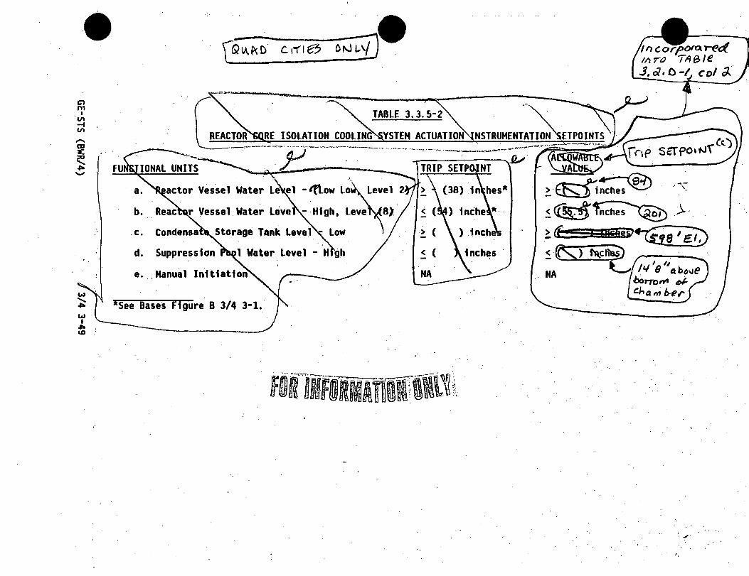
Cl m
I VI .... VI
FU
b •
. c.
d. Suppression
e.
*see Bases Figure B 3/4 3-1.
NA
,·
In co rf!._orot red //) r() Tit a 1e .J, ci, o-~ col a..··
' . ..,.
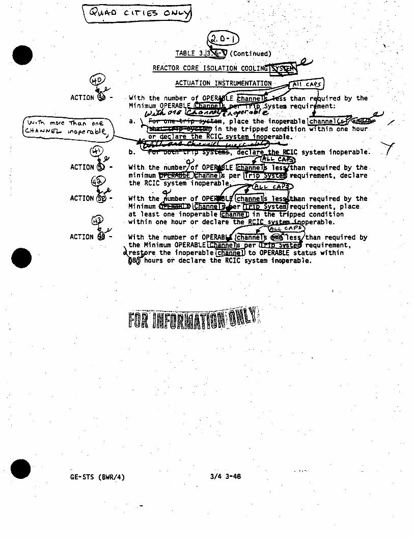
,. TABLE 3. 3. - (Cont.inued) '
~ ACTIO ;.;_
REACTOR CORE ISOLATION COOLI~~ ACTUATION INSTRUMENTATION··
IJ.J 11\o... 'f'l\OtC .,;.. 0. f\ CM e. C..~A ~N€1_. 11\0 pe to bl t
J
ACTIO~-b.
~ . ACTION -
~,Al ACTION Q - by
GE-STS {BWR/4) 3/4 3-48

Cl rn
I
·~ Vl
w ~ w I
U1 0
[Qu.w crne5- . Qf-lt..YJ • ----~~~~-------- . ~
-~,m- . --lf"-l'{,(\ TABLE 4/!:~ HR INFO Vil CORE~JSOLAT;!~ COOLING !Ji:t.;i;-;;~ ACTUATION INSTRUMENTATION SURVEILLANCE RE UIREMENTS
FUNCTIONAL. UNIT'
. a. Reactor Vessel Water Level ~Low Lowt9"si ID~ .
. CHANNEL CHECK
s b. Reactor Vesse~l Water · J;: S
Level - Hig , . (Tnf) ' '
c. Condensate Storage Tank . level .... low ·
d .. Suppression~Water L~~el . High ~
e. Manual Initiation · NA
CHANNEL FUNCTIONAL
TEST.
·M
M
CHANNEL CALIBRATION
NA ·• ' ---
~:::::;;:;:;::~~;;~~~:r.;::::::--:::::-:--:b:e~:::"~-:r....-i:~;:;:~E~p~e~~~l~l:-:"mo~n~t:h~s~·u=~7tn:·g:-:'s~hu~:::'.'ow~n~.--.A~l~J~~o~t~h~~\::~ ·' e a CHANNEL FUN IONAL TEST at least. nee . · r automatic sys m ~ctuatio .)" ..
. t::.p.I.; t>><- . ,,;:...,,.., . ,.... __
'~·

INSTRUMENTATION --.-.:__.:.---~--.·. -. """ : · . · _ ·. , .
@fiijJ r6aef tis:i~::~12~:i:t~iik AClllAnoNi@;AUMiliHt!Ql!
•· '3. (;). LIMITING CONDITION FOR OPERATION
_,. __ - ___ .. _ .. 13
11·-.. ,-.- .. --
ACTION:
a .
. ~ . · !61)t4-no11 t:.c11de11ser
c&;--0))- Each actuation instrumentation. hann shall be demonstrated· OPERABLE by the performance of the CHANNEL CHECK, CHANNEL FUNCTIONAL TEST and CHANNEL.CALIBRATION operations at the frequencies shown in Tabi;.. 4·.Ss5 1-~ · . . ·. .
~ LOGIC SYSTEM FUNCTIONAL TESTS and simulated automatic operation of all ~s shall .be performed at least once per 18 _months •.
cEO L,\, l §) . . .
FOR'lNFbRMAtlW'll,~
GE-STS (BWR/4) 3/4. 3-46
;·.
\ · ..

Cl m
I V'I -I V'I
~E~DEl--' OtJt-y
f0flNFOHlll1i\\i .. I
FUNCTIONAL UNI~ ~.,.,e-~ a. Reactor Vesse~ LO~.(~gw tow, teVi!
'
c.
d.
e.
• ACTUATION INSTRUMENTATION
2
ACTIO!! . (§.0) ~~-
. . ~ \010 ~\.~
.fOc z. \5 se.co"(lls,
.,,.

·. :- ....
. ~·ClflNFlJRMlfiMf i\\{\1 . TABLE 3 •• - (Contl~ued) ~ . CRElle10R c@ISOLATION (gr@ '*1 'vSffio . . .
ACTIO~ ACTUATtON INSTRUMENTATIO
With the. ;fiumber of OPERABLE channe s ess a minimum OPE BLE channels.- per :ip Systeia r.equirem the RCIC syst inoperab 1 e~ ·. _,; ,,
With the number o OPERABLE channel . less than required Minimum OPERABLE ·ctl riels per Trip. Sy tea requirement, pl at .least one inoperao channel fo the ipped condition
·within.one hour or dee the RCIC sys inoperable.
h the number of OPERAS hannels one les · than required by the. inimum OPERABtE Channels er Trip System quirement, resto · the inoperable channel OPERABLE statu witMn
ACTION.53 -
(8).. hours or declare the RCIC system inoperable.
l)J111.. M.ore +-ha.tt ,, nil.. ~J.IA-AJN£l- ,,:,,,pera b l<J rJ ec..Jare rhe. 1~0/~ r/o 11 ctuider1 se.r sy,.rem_ 1flOl'e~C#bl_~ ~ --~~
- -· . GE-STS (BWR/4) 3/4 3-48
\ •.
~.·.

Cl m I
·en -f
"'·
w . ........ ,,,.., wj. I . ,,,. :.
'°"
TABLE 3.3.5-2
REACTOR CORE ISOLATION COOLI
FUNCTIONAL UNITS
a. - lf\.ow low,
. b. Reactor Vesse Water Level - Htgh, level t<O) ·
c. Condensate Stor e Tank level - low
d. Suppression Pool W
e .. Manual Inhtatian
•see Bases Ff gure B 3/4 3-1 •.
TRIP SETPOINT
~ - (38) inches*
(54) inches*
> ) inches
~ ( ) inches
NA
~-----·-----···----... -'----~----~~·~~-------
ALLOWABLE VALUE.
) inches
5.5) inches . "·~
) inches
~.( ) inches
NA
>·

Cl m
I
. "' -I
"'
FUNCTIONAL.UNI~
c. Co ensate Storage ank · level :.. Low ·
· Suppression ~ High
TABLE 4.
ACTUATION INSTRUMENTATION SURVEILLANCE RE. UIREMENTS
. ,
< 3 e, ......
·: · . . _,,.
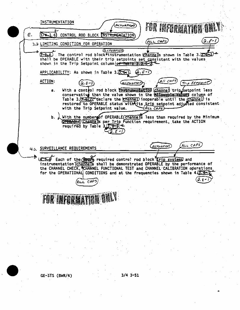
. INSTRUMENTATION
3,~ LIMITING CONDITION FOR OPERATION
4-.1-. SURVEILLANCE RE UIREMENTS
GE-STS (BWR/4) 3/4 3--51

• C> m I
(/)
~ (/) .
w ...... -I>-.
w ·' ' U1 N
"
\AN\
y- ROD BLOCK HONITOR(a) K. Upsc&.le · b. _Inoperative
~c:~· Downscale 2. APRM
Upscale(c)~
4.
~·
2 3 2 3 2 ·.
3 2
6. 6 6 6
2 5 2 5 2· 5 2. 5
2,5 ~··~~····· ... 2, 5 2, 5 2, 5 .. ~
~~··e; .. · 62 ~: 62·' ..
. '62"' I - .; .
, .
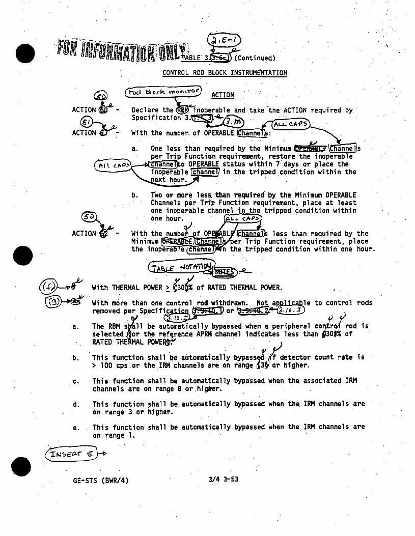
•
••
CONTROL ROD BLOCK INSTRUMENTATION
ACTION.
ACTIO:t.- - required by. ·
~ -ACTION~-
a. One less .than. required by. th~ Minimum lbern'in;:li \C!iannej)s . per Trip Function requirement, restQre·the inoperable
A 1 1 r--...-...;~a::..:.:nn~e:;.i o OPERABLE status ·within 7 days or pl ace the ~-- inoperable c anne in the tripped condition within the
b.
®'_
ext hour.
Two or more 1 ess. than requfred .. by the Mini mum OPERABLE Channels per Trip Function requirement, place at least one inoperable channel in the. tripped condition within one hour. · A1.1.. e.AP~
ACTION e.._.. - BL 1 less than required by the Mrni~~~~~"r\ per Trip Function requirement, place
a.
b.
n the tripped condition within one hour.
· . . Gee,g t-Jo\A-~~ .
With THERMAL POWER ~ {30~ of RATED THERMAL POWER.
With more than one con~rol rod withdrawn. y:: _ap,.pli~e to control rods removed per Specif~ or '3. 9. ~~I#.:_ :I
The RBM sEl be aut~~:·tically bypassed when a peripheral coJ.irod is selected or the ~!~~ence APRM channel jndicates less than ~30~% of RATED THE L POWEP{r." · · ·
·This function shall be automatically bypass,,! ·.tsetector count rate is > 100 cps or the IRM channels are .on range ~3~~/ higher •
. c. Th1s function shall be automatically bypassed when the associated IRM channels are on range 8 or higher •
. d. This function shall be automatically bypassed when the IRM channels are on range 3 or higher. · ·
e. This function shall be automatically bypassed when the IRM channels are on range 1.
6'N~€(l..-r'. i)~
GE-STS (BWR/4) 3/4 3-53
,.

----------~--------~:--~~--~---' ,.,,,.,....-:-
G:N~i b°) · .. · {~=~ STS ~~6 ~ $,~, ~:ij"",,,;J,P0-~?•'"'•·-~r •-·• n-• ... - . ; ) . . . . . . . . . " . " " ..... . . . : l~f The Average Power Range Monitor rod block function is varied as a function of recirculation t. .'. · drive flow.(W). The trip setting of this function must be maintained in accordance with · · -i · .. ' Specification 3. 11.B. W is equal to the percentage of the .drive .flow required to produce a · '\:" . · rated core flow of 98x106 lbs/hr. ·· . · · . ~------'---·----_./ ·\
(i) Shall be ~ 0. 7 cps provided signal-to-noise ratio is ~. 2.0 ..
(j) Required to be OPERABLE only d~ring SHUTDOWN MARGfN demonstrations performed per .. Specification 3 .. 12.B.
-- ... ·-~~ ·---· ~--·- ... ··-....... ·--:· ···-'=" ~- , .. - ... - ..
••
•

C> m
I
·~
"'
w .........
"'"' w I
U1 ~··
,,...--. --......._.:__ __ _ TR IP . FUNCTION
1. ROD BLOCK MONNOR Upscale Inoperative
· Downscale
(h)
l.tlt.1q I R.eclf'<ular;014.9P ~f~ran'u~ ii. (o,SBW,. S'O) ~h)
·-----------------r~--~:--~.'-.:~~-: .. ~~.'.:~":"r'otl L-0°f' c)pt>r~r,.~ ; ( o .saw14i;,s) · , .. I ---TABLE 3. 3. 6-2
I CONTROL ROD BLOCK INSTRUMENTAllOH-S~TP.DINTS
i'·. l '~· ·,
2. . AP M
3.
4.
5.
Flow Biased Neut on Flux -Upscale ·
b. noperative c. ~~nscale · . · d. N\utron Flux - Upsca e, Startup .
SOURCE RANGE MONITORS
<. 0.66 W + (42)%iiL NA · > (5)% of RA D THERMAL POWER ~ (12)% of RA 0 THERMAL POWER
· a. Det ctor not ful 1 in NA b. · Ups le < (2 x 10⁵) cps c. ·Inoperative RA d: Downs\ale ~ \(3) cps.
INTERMEDIAT RANGE MONITORS .. \ . . ------ . . .
. :::~~~~: full n HR l~f~~~-f(,Tttm J\\~lvlslons of· · Ill l n fu-11 SC e . . .
of·
a. ) inches b •.
6. REACTOR COO NT SYSTEM CIRCULATION FLOW a. Upscale ··
b. Inoperative (Comparator)
< (108 25) divisio s of - full ale NA ~ (10)% flow deviation
... ~-· ·. t ..
verage er on or ro oc function. s var e as a function of .rec;:irculation The trip set~ing of this function must be maintained in ~ccordance with __ Specific~t,ion · 3 ...... ~,...-~~4;:-::::;...
· 1.s e9'_ual ro -me perc~1>TAyt.. ~ 111@ . t:if"1 vt +tovJ .retu.ir-ed -ro produ~ . . a n.1.:r-e.kl. Co~C? .+le~ ol C/8Jr 106 //Js/1,.--,. · · .. · . . . ·

• Cl
"' I .VI -t . Vl
w ....... ~
w I I
U1 . U1
TABLE 4 ..
CONTROL ROD BLOCK INSTRUMENTATION SURVEILLANCE REQUIREMENTS
CHANNEL .CHECK
CHANNEL FUNCTIONAL
TEST CHANNEL
CALIBRATION( a)
1. ROD BLOCK MONITOR
. a. Upscale NA S/U(b)(c) M(c) Q l~· b. · Inoperative NA S/U(b)(c) :M(c) NA · 1 . . · c. Downscale NA . S/t.i(b)(c) ,MCc) Q . 1 ~)
2. ~ ·:I .....
a. Flow. Biased Ne~. flux ':" ¢tt:; . ~ · _ _.. 4!pieat1~ · . 'U!!!!.!!!L~~ ~==-=~s~~~~-~-e·=:·"::·::=:Sitia~> ::::-::0~· :::=:::::D1r · ~· ) ·
.b. lnoperative . . \ NA _..;;,,- S/U(b) ,M . N~A 11. 2. 5 (K .
c •.. Downs ca 1 e . · · · . n~NA~ . .h SIU M d. Neutron Flux - Upscale, Startup ~NA.Ir"'- ·. S/U(b):M SA 2, 5 · .
3 . SOURCE RANGE MONITORS . ~- . ~r j) a. Detector not full in NA S/U~:~.w Nk · · 2 b. Upscale~ NA. . S/U(b)'W .Cffv•· · E 2, . c. Inoperat1~ -@ .NA S/U(b)'W NA . ·· . 2, 5 ·. d. Downscale NA S/U .. ,W • 2, .
4. iNTERMEDIATE RANGE MONITORS ~ . (b) 2.·· 5 (i)
a. Detector not full NA . .S/U(b)'W ·NA· b. ·Upscale NA S/U(b)'w ~~£. · · 2, c. Inoperative NA · S/U(b)'w NA 2, d. · Downscale NA S/U W d)!: · 2 ·
5. SCRAM DISCHARGE VOLUME ~ . ~ • (;!@) (!!) eQf ~..@ 1, 2. ~~ M .NA (l,_2,)5
\. b11io\ t.et.\rt~lO..T\tl~ Loop e~ero:r1ot\ ·. · .
, ~. s 1 ~h~~~~~':''1.4\0.'T'1on .. L.oof .. ·
' . ..,.
·.·.

.FORlNFORMitld',UillrAe~E 4· Q.f-1 CONTROL ROD BLOCK INSTRUMENTATION SURVEILLANCE REQUIREMENTS
NOTES:
@~t.€ tJ0~~\09 .
a.
b.
Neutron d'!t~ors may be excluded fromCHANNEL CALIBRATION. .
Wjthin ~s prior to startup{ if Re~ pevfeZtea w;\~iA iih';J
, ..
QPevj QW9 7 d&j!) · . . . .. . . It ·· . . <elo..y se lec.r .
NIO.:rr Ile
••
GE~STS (BWR/4)

•
. ~- ---·---=~ .. --...... -···-·-.....:...--··
(f) This function shall be automatically bypassed if detector count rate is > 100 cps or the IRM channels. are .on range 3 or higher.
I
(g) This function shall be automatic;:ally bypassed wh~n the associated IRM channels are on range i
\ · ..
8 or higher. . · · · · · ·. -. ·· . . j
(h} This functiori shall be a~tomatic~lly bypas~ed when the I.RM chmlllels are on range 3 or higher. \ . . . . '.\
(i) This function shall be automatically bypassed when the IRM channels are on range 1 . \ . . . \
(j) The provisions of Specification 4~0.D are not applicable to the CHANNEL FUNCTIONAL TEST I and CHANNEL CALIBRATION surveillances for ent,.Y into the applicable OPERATIONAL. \. ·· MODE(s) from OPERATIONAL MODE 1 provided the surveillances are performed within 12 . .\ hours after such entry
(kl Required to be OPERABLE only during SHUTDOWN MARGIN demonstrations performed per · \ Specification 3.12.8. i
______ __.:__ ____ ~_...___------··--·----_/ I i

~I-NSTR---.UME-NTAT-ION ~--f0 ............. 11NfODAttTOtfll\\\l1f · ACCIDENT MONITORING
~ LIMITING CONDITiON "FOR OPERATION
3.3.7.5 The accident monitoring instrumentation channe s shown in Table shall be OPERABLE.
ACTION:
With one. inoperable, take the ACTION requ fr.ed . by Tab 1 e · 3 . .....,. _.....-i
SURVEILLANCE RE UIREMENTS"
-1'!1 2 ) fJ' Each of the above required accident monitoring instrumentation ....,.M&.U~s shall be demonstrated.OPERABLE by performance of the CHANNE CHECK and CHANNEL CALIBRATION operations at the frequencies shown in Table 4.~. g~
· GE:..srs (BWR/4J 3/4 3-73
\.
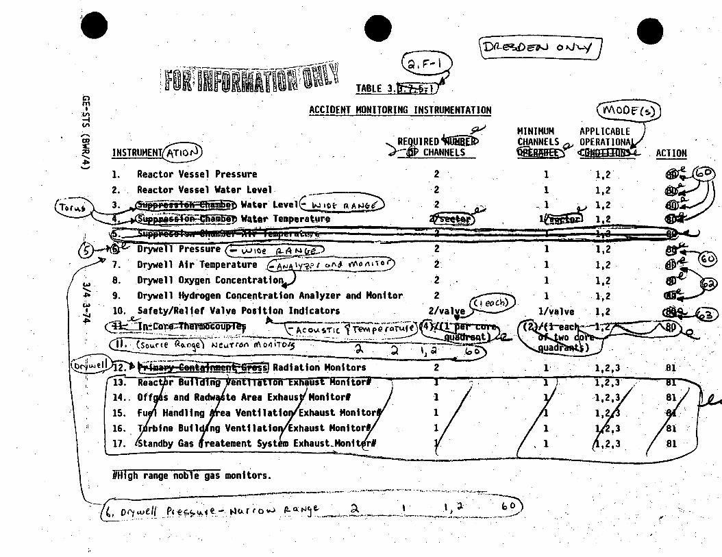
C> m I
:vi .-t VI
.. ,
TABLE 3.
ACCIDENT MONITORING INSTRUMENTATION
INSTRUMENT(§~~ 1. Reactor Vesse 1 Pressure 2. · Reactor Vessel Water Level. ------
......__!.;.~'!!~~~!a~~a~ Water· Leve1E w 1ot- ~A r-J!'O
. ~
'- REqµ I RED 't1uiiEiz> . J"-GP CHANNELS
2
2 2 . . ..._
u · ...... ~p:- a!ll a WQt.1r Temporatpro s.,~,;eii 1 :a ~~af·-~·! )!~;, att4P ~ _: : : __ j · -Drywe 'il Pressure - w 1oe 12- A N ~ . . .
~ -- 3 ': .. : --: ...
7. Orywell Air Temperature __ "' 1 -3,-;,1 "'"~ ~~0 . 8. Drywall Oxygen Concentratton 9.
lS.
16. 17.
ea Venttlatto Exhaust Monitor ng Vent11atto Exhaust Honttorl.
Exhaust_Hontt rl
#High range noble gas monitors.
2
· -({;_ori .,e11 ... ~· ~~~~· • -' .iu =::;=~.-~~--=-::.~· --=~-~i:=-~J})
ACTION
1 1,2 .
1 l,~
1 . 1,2
... 01·
~·
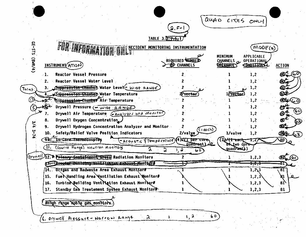
1!. ~ '.
'
C} m
I . Vl
-4 Vl
·,
15. 16. 17. Standby Ga Treatement Sys m Exhaust Monitor L.:...~----::....=..-~~:__----__:~---,...,_ --. ... _ ..... ··- -.···-···---·
l,~· 1,2 ,3 . . .
1,2,3
1,2,3
. _,,.
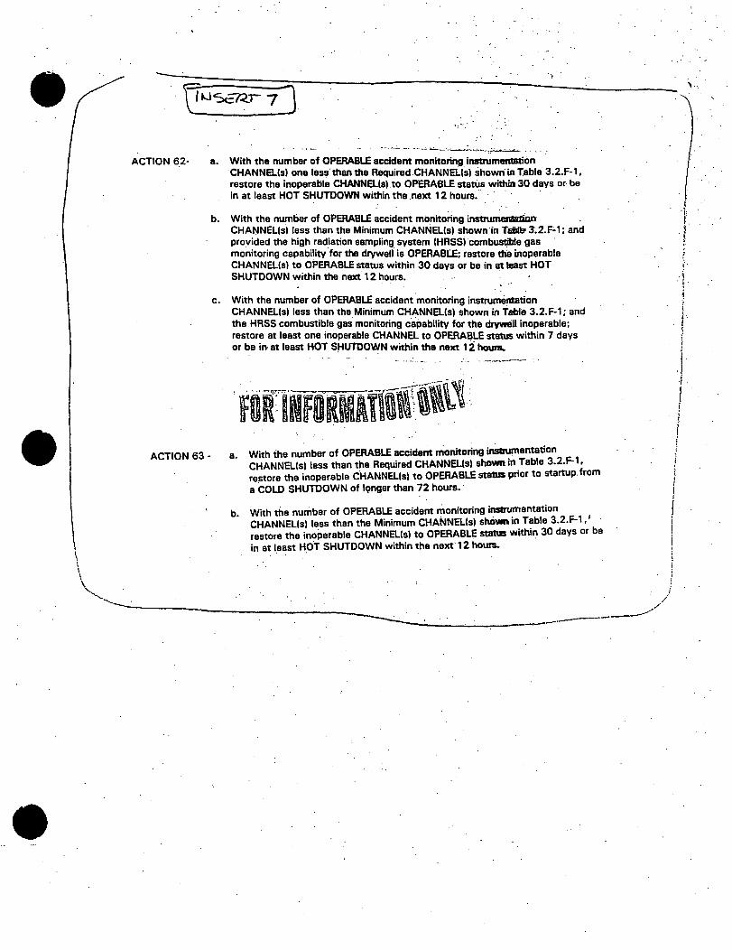
ACTION 6_2-
ACTION 63-
'i>
a. With the number of OPERABLE accident monitoring instrumentation CHANNatsl one less· than the Required.CHANNa(s) shown· in Table 3.2.F-1, restore tt:ie inoperable CHANNatsl .to OPERABLE statiJs within 30 days or- be in at least HOT SHUTDOWN within the next 12 hours. ·
b. With the number of OPERABLE accident monitorlng instrumell&UiCn CHANNEL(sl less than the Minimum CJ-iANNatsl shown ·in Tdll:r 3.2.F-1; and provided the high radiation sampling system (HRSSI combustible gas mo.nitoring capability for the drywall is OPERABLE;. restore ~ inoperable CHANNatsl to OPERABLE status within 30 days or be in at least HOT SHUTDOWN within the next 12 hours. .
c. With the number of OPERABLE accident.monitoring instrumentation CHANNa(sl less than the Minimum CHANNa(s) shown in Tallle 3.2.F-1; and the HASS combustible gas monitoring capability for the drywell inoperable; restore at least one inoperable CHANNEL to OPERA~LE status within 7 days or be in- at least HOT SHUTDOWN within the next 12 hounL
a. Wi~h the nu~ber of OPERABLE accident monitoring inSuumentatio3n
2 F-l
CHANNEL(s) less than the Required CHANNa(s) shown in Table • • • restore the inoperable CHANNEL(s) to OPERABLE statuS prior to startup. from a COLD SHUTDOWN of l9nger than 72 hours. ·
b. With the number of OPERABLE accident monitoring instrumentation CHANNEL(s) less than the Minimum CHANNEL(s) shOwn in Table 3.2.F-1,' restore the inoperable CHANNEL(s) to OPERABLE status within 30 days or be in at least HOT SHUTDOWN within the next· 12 hours.
- . . . ' -----------------~~~~~~~~~--
/ ,/
i i .. l >
I· )
J j
I ! !
r ; ; I
i I i j i ! i ) } i ;
\ ...

\ .
.
ACTION
~1r'her re~rr;re ri)e . ,,,,o,e1ab/e CiM-AJNEZ.(s) 10 '51At.11A.4 t,,AJ1~,""' 7olrA. s ·o-1- The.. ~ve"1 r or-------,,
GE-STS (BWR/4) 3/4 3-75

•
Cl m
I . Vl -i Vl -· m ~ :0 ....... ~ -
TABLE 4.
- ACCIDENT MONITORING INSTRUMENTATION SURVEILLANCE REQUIREMENTS
INSTRUMENT·~-1. Reactor Vessel Pressure 2. ·Reactor Vessel Water Level ,.-----
:-.i:-~jpjteHt Og: Ehnhit Water Leve 1 ~~4 n~ .. 4. Water ·Temperature
CHANNEL CHECK
M
M
H
H
CHANNEL CALIBRATION
~L@)' ~-
~
APPLICABLE OPERATIONAL CONDITIONS
1,2
1,2 1,2 1,2
· • . . C§i 5wpp;ueh5 • HMeap lb I 1peaatlifjr&-" ~· --- ·Pressure
~ M
H
HM
M
M
~ ~12--1,2
Drywell Air Temperature _ Dr~el 1 Oxygen Concentration... . _ l)rywell Hydrogen Concentration Analyzer and Monitor 9.
1,2
<i>~ 1,2.
~ 1,,2
~-- i,2
~ . 1,2
-~- 1!2.~ R
H
15. 16.
M
H
H
M.
M t Monitor# R
Us ng samp e gas containing: a. One volume percent hydrogen, balance nitrogen. b. Four volume percent hydrogen, balance nitrogen. . .
HANNEL CALIBRATION shall consist of an electronic calibr~tion of the channel, not including the detector, for range decades above· IO R/hr and a one point calibration check of the_ detector below.lO·R/hr with an installed or portable gamma sourc~. · ·
~~ga;;nobl!._g!!:!Oni;t"c»irD. t, t-ltu:no" chttc.,.~!~ "'a.1 k--~~l""cAed .f.rotl\ ~e C~~~,~-.:-~~~ta~~I.~2-~·
p,e ~';Ju. r~ - 1--lcH 1 e> .Jo.) R"'"~e. M c IJ ~ ---------~---~~~~~~~~~~~~--~~~- ~--~--
. ..,.
\ ...

. .
C> m
I . VI -i VI
• TABLE 4.
ACCIDENT MONITORING INSTRUMENTATION SURVEILLANCE REQUIREMENTS
INSTRUMENT~· 1. Reactor Vessel Pressure 2. Reactor Vessel.Water Level
CHANNEL CHECK
M
CHANNEL CALIBRATION
APPLICABLE OPERATIONl\L . CONDITIONS
1,2.
. ~ · · c..u1ele R."nae
T~~:::: ;i :;;:;~~:;:~:re J
M
M
M
. 1,2
1,2
1,2 1,2 1,2
1,2
M
~· Pressure M ----....... Drywell Air T~mperat~re ·. · G"°AM 1 Y~fr al'\(,\ MoAiror) H
w ...... .,.. w I .....
en
9.
10 .
. Drywel 1 Oxyg~ri Concentrat 1 on_~~ . . . . Drywell
~1.(E~~~~~
M
·H
H
H'
. .
.
·1,2.
1,2
.1.2 1,2
1,2~3
·~·2~3 . 2 ,3
1, 3
1,2,3
Standby Gas Treatment System M \
1,2,3. '
ng samp e gas containing: One volume percent hydrogen,· balance nitrogen.
b. Four volume percent hydrogen, balance nitrogen. L-"=-.HANNEL CALIBRATION shall consist of an electronic calibration of the channel, not including the detector,
for range decades above ·10 R/hr and a one point calibration check of the detector below.10 ·R/hr·with an installed or portable ganuna source. _ __..,--~----~ .......... ····-· ............... ·--~-·----.__.;..., .. ,,__. ___ .;._ ___
<iffl)!F'iAga31oble Q&S !JDil~ . . ~t:Tec. Tor(, rr-o..y ha e.1tcl"'"d.eJ ..fs-ot(\ 1'\>.e C~~Nt-l ~ CJ.i.LAiA~TtotJ . . . .'_ ·.

- ~. ...:, : .
INSTRUMENTATION
'· .
. shall be OPERABLE:
b.
APPLICABILITY:
ACTION:
a.
@v.1\D--__, @suRVEILLANCE REQUIREMENTS
be
·.X
. ·- c~- °11\~· ,;ro-~-.~.~ll~ o-(."~pec.1.f1c:~TH~I\ ·'f.O.D c:tre nor ecpPl1~Able.. +or erirry INRl Tlte qpplicq ble CJP€7LATIOAJA-t- MOO€(s) ~"m aPC1U4r10NM .. MCOF j /J.rt>v1tiPe(. n,e ~C...rve,/~1'14: IS per.fo.rMI!'.{ w1/111n Id_ h()•U!. Q.?t"er J"'.,(C.J.. .'2~'M"'Y.j-~----""'

•
~l!,STRUMEN:rAflO \ .
\ TRAYERSING IN-CORE PROBE SYSTEM
\ LIMITING CONDITION FOR OPERATION
3. 3. 7. ~ The .t rave rs i ng i n-Co re probe \ stem sha H be OPERAS LE \ ~v'! \
\ ..
a. ~rel! movable detectors, drive51 and
b. r::ex f ng equf pment . to a 11 ow a 11 . . '."~ detectors to b! ca 1 i
the ~ore,/ 1n · /
a mmon location.
APPLICABILITY:·. When the.traversing in-core used for:
a. Recali ration of the LPRM detectors and
b.* LH~R I MCPR ~ 0 _pl>F) ..(MFLPDY.
·ACTION:
With the traversing n·core probe system inopera le, suspend us·e of the sys em for the above applica le monitoring or calibratio functions. of Specifications 3 .. 0. and 3.0.4 are not applic le.
traversing in ore probe system shall be demonstrated OPERABLE by required detector output within 72 hours prior
~we-at:m+mmt-e-im:mrr· ttn'"1·mr,,... ca 1 i brat n functions.
(
I I I \/
! \: I
!
.. \
I I ' I . *only the detector(s) in the measurement lOcation(s) are required to I \ be OPERABLE. I
\'----~--~~-;.__--.~~--~-,:___~~~-----)
GE-STS (BWR/4) 3/4 3-78
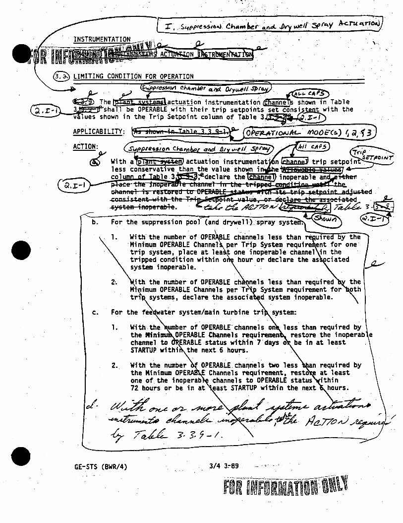
•
•• 1111! ...... .
. · INSTRUMENTATION .. · ·. · ·· : ' . . . ·• ·
-fflN--~N$£JRb!!EN'Mr§r°- . ~ LIMITING CONDITION FOR OPERATION
b. For the suppression pool {and drywell) spray syste
1. With.the number of OPE LE channels less than uire y the Minimum OPERABLE Channel per Trip System require ent for one trip system, place at lea t one inoperable channel in the tripped condition within o hour or declare the as ciated r t? ~ system inoperable. . _.-
2·. ith the number of OPERABLE ch nels less than required M imum OPERABLE Channels per.Tr" System requirement for tri systems, declare the associa. d system inoperable.
c. For the fee ater system/main turbine tri
1. With.the. umber of OPERABLE-channels on less than required by the Mini OPERABLE Channels requiremen restore the inoperab e channel to ERABLE status within 1·days o be in at least STARTUP withi the next 6 hours.
2. OPERABLE.cha~nels two less an required by
GE-STS {BWR/4)
. Channels requirement, resto at least one of the inoperab channels to OPERABLE status •thin 72 hours or be in at east STARTUP within the next hours •
3/4 3~89
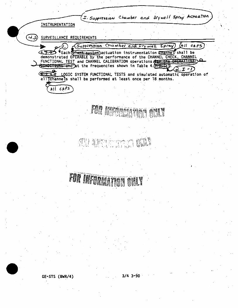
,.
GE"".STS (BWR/4) 3/4 3-90

w I
•
~-
• . 1 S4pp.ress1or'1 Cho.mbe r . ~
Of\<A. Dr't u..i e 11 S f'o..'I ,,---- ~
TABLE ib';ij)..e...-
ACTUATION INSTRUMENTATION
d .. · imers ~ ·
·_l) Syste~
2)
2. FEEDWATER SYSTEM/HAIN TURBINE TRIP.SYSTEM
1
MINIMUM OPERABLE CHANNELS.·
a. Reactor Vessel Water Level-High Level (8) 3
l;,~ .. ~--P .
._A... ..
I
I
. ~·

\ l l •~I :~(
f b
1 l I
\
::::-------~----·--~---.\
~
ACTION 80 - a. With the number of OPERABLE CHANNEL(sl less than required by the. Minimum OPERABLE CHANNELlsl per TRIP SYSTEM requirement for one TRIP:SYSTEM, place at least one inoperable CHANNEL in the tripped condition"" within one. hour or declare the suppression ·Chamber and drywall sprays inoperable. ·
. . b. With the number of OPERABLE CHANNELlsl less than required by the ·Minimum OPERABLE
CHANNELlsl per TRIP SYSTEM requirement for both TRIP SYSTEM(sl, declara·the suppraulon chamber and dryWell sprays inoperable. · ·
Reactor vessel water lavel settings ara expressed in inchea above tha top of active fuel (which la 360 inchu·above vessel zero I.
. . . II en instrument la inoperable, It 1haD be placed (Or 1bnuletedl In i tripped condition oo that It wlD. not pm111nt a coritalnment opray.
\ ' .

.. I ! i
l \ l
.· . : . , ~ . . .:· ·~·.
•, '~< .. ~~--~ .
. ~-
7'/l~t-E j . .7 •. '?'-·I <Cu',;.: l.· .... eJ)
~I. .4 "-' 7 ~ S T'S .,-CM>'
\ ·.-. __ .··
JJc. r11.J rs - "~ ~ ~ of·· ttl4du: ~ ~ ··
~- ,-c 'f; . .:....J>A, ~ _·/i1_. • tJ"~"AllLli l ~--~.. ,.>- T-f. S-r7° ·. f'- .r-< \ r ,..£,. J ...l.14 · . ..;.. ,_,v·~ \
~OffllmiRMltllif ~r~1~ ~ ~ c.- ~ r.: .-J.<.:_ .,...,_ · \ ~ "'-4-c.L--u. P.. 01- • r. . -&.J -"""" '~· z;; . ..
~- -~"' ·o-j o 1'£ ~A 8~ ~ J.-. ..... L ~ ...v..._
~ Ol"t:~lfd~Z C!k '"° . • .. • i
~ra-- ,.cl(!~~-, r ,/rU. ~ ~- z; .. ~
.-UIO"'I:.-""'.... ~ .. .:.._ ~. . . . J
• . . - \ ! Ii
/llC. T IOAI t t&JJ:J._ ~ .- •• /..•· "( 4,IE Jr ..A..l-. ~ ~jl...
. . , I
A.'1c:«:....lt, ;z:k ,AG;;~ - ()A . A8£E ~ I .,4 ,....., .. :.·. i 1 : I
. -~~ J..,,-iJ dt'elt.Alll.E~~
rt ,/.t .,;,._ J ,t._1 STAil TU' . . ~ ~ (, ~ i '
i h I • \ \
. \ ~ "»o«.~~ 1 tJit'c-,eAJIL£ ~-""4. ,;A:-.-~""Z-""''-
I '
""f',.:.J? +~~. ~.
· ~ ~ ~ :..rt.a.: o .,._tf,,. J.. -~L f. O/f11:E'2.,IJl#t d>l;.t&..- ... ::z4 • 71.: .... "1 ~ ~ ~ ~--r:"'~ T-'-f1'.,,.. ~'- •
. ~ ~- ··'· ~- :." -~--~~TfJ--'-~-
6' E - s-rs · (4w1'.//)

Cl l'T1 I
"' -t
"' ,. -ca
... ---.. --.. --.... --··---··~--
·-----......... ""--- 9.-/ ----·-----~-~
~ ··.~· ------ : . .
--- ·--"'Llol._, .. -·-···-···----· . TABLE 3.'""""'"~
SYSTEMS ACTUATION INSTRUMENTA
.' ~ ALLOWABLE "'" VALUE .....,
·w ·~ ~ ,;1 ID N
a. · rywell Pressure-High b •. · ntatnment Pressure-High c. R actor. Vesse 1 Water leve 1 - Lo~ Low Low, Leve 1 1 d. Ti ers . \
1) \. System A· · · · \ 2) . System B · · . · ·\ . .
\ . . '
• FEEDWATER S"STEM/MAIN TURBINE ·TRIP SYSTEM\ · ·.
a .. · Reactor \~ssel Water Level-High, Lev~1·\~) 2.
•see. Bases Figure B 3/4 3
< (1.6 ) psig < (35) sig ~ -( ) sig
< (12) mi utes · ~ (14) mtn tes
.· ~ (54.5)
i . 1.89) psig < ( ) psig ~ -( ) psig
<
,,,.
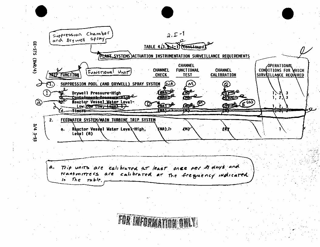
Cl ITI I
·~ VI
. s'"'rp•e~u>" Cho..M \)er o.rir)... .1>r·t~ell ~pru-y
~ .1: ... 1
.TABLE4b~~ YSTEHS ACTUATION INSTRUMENTATION SURVEILLANCE RE UIREMENTS
w ·.c~-2. ~ a. !w , I
,:~
.\\ \ -----·-:------~-----~·--· .. -··--···--··---·---..-..·-----·.;__ _ _,..,... __ --:_:_
Ti'··~ ~t'•r!:a ·~rt ~4/1 bro.Te«. ~1- /t!A6r c11ce pet' .-'I ~~yj· .. "Qf\~ t.rt1..i1S~1-rr~ <.s o.re cAlt br-~reA «,.. ·.,,..e ~re~e "''I 1114'..1c4~it· ·
1~ the rit~lf.,-------~-----------------------~-------------~
-·
-~ .--:· .. ~~>~T ·. :.·:-'·'1·
.· .. ; ': :: ':;;,~' ::
...... '
: ;'
•'' . ,.
. :, ·.
. ~·
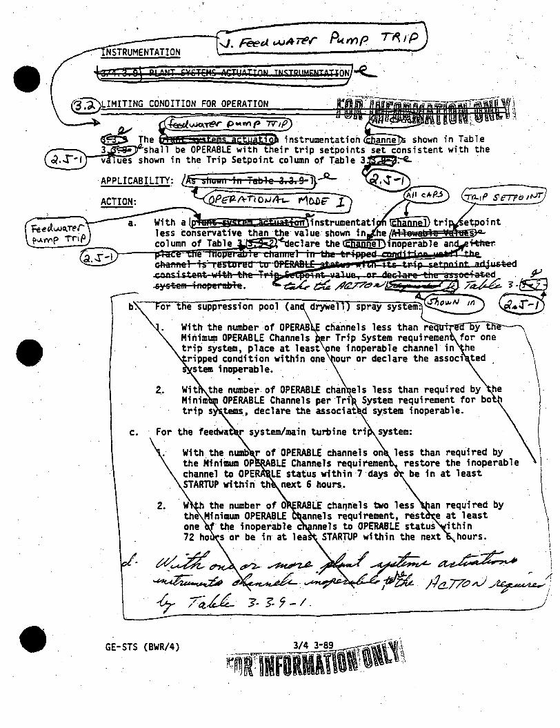
••
~-----+-..J. Feed ~Aler Pwmp NSTRUMENTATION
-Q,iq~11 p1.i$;i1:r &¥HEH& "':ruPnmi UISTR"MEtuATi§l-E.....
LIMITING CONDITION FOR OPERATION
T~rp
spray sys
channels less than req
in Table the
Minimwp OPERABLE Channels r Trip System requiremen for one trip system, place at least ne inoperable channel in he ripped condition within one our or declare the assoc1 ted stem inoperable.
i. Wit the number of OPERABLE chan els less than.required by he Minim OPERABLE Channels per·Tri System requirement for bo · trip s tems. 1 declare the associat d system inoperable.
c. For the feedWa r system/main turbine tri system:
,.
With the numt> r of OPERABLE channels on less than required by the Minimum OP BLE Channels requiremen restore the inoperable
2.
..
channel to OPE LE status within 7·days be in at least STARTUP within th next 6 hours. ·
. ·.
· W h the number of 0 RABLE cha~nels two less an required by the Minimtim OPERABLE annels requirement, rest e at least one f the inoperable c nnels to OPERABLE status· ithin 72 ho s or be in at lea STARTUP within the next hours.
GE-STS (BWR/4)
\
\ \ I I
\ i

•
INSTRUMENTATION
.J, <f"? I '$- Each btia\ sirs•nm as*wai'iorinstrum~nta~ion shall be demonstrated OPERABLE by the· perfqrmance of the C~ANNEL CHECK, CHANNEL · FUNCTIONAL TEST~nd .CHANNEL CALIBRATION operatfons([1: bA@ gp$1ilAftoN5;:7-'2-~BTTT11&$ an91 at the frequencies shown fo Table. 4. . .~. . ·.
P-" . . .· : . ,J·I . ~";~~~ ... ~~~L~O,GIC SYSTEM FUNCTIONAL TESTS and simulated automa ic operation of
channel shall be performed at least once per 18.months. ·
GE-STS (BWR/4) 3/4 3-90

• . tftif\li0ftil~1~~ ~ TABLE 3 •• -1 JU I\\ . · F'e e (",(. ""'"' .J- ,; J: p v. ('(If,._ l::!t:--,,,-.,-5~-,&-JE_M_&_A_G-TY_A_T1_8"""\~ INSTRUMENTATION -t -rP- •r VI
~·. - ... ....,.,, •:=.~1111·. . • ._.. • -·-- , --~-~
SUPl>'RESSTOtrl>oo[(AND DRYWELL) SPRAY SYSTEM I '-:....
Drywel 1 Pressure-High·
b.
c. Rea . or Vessel Water level -
d. \" .,
" . 1) ,. ·. System B
2. EM/MAIN TURBINE TRIP.SYSTEM
a. ·Reactor Vessel Water Leve1-H1ghe--a-rte~1-(~e-=?)
MINIMUM .OPE.RAB(E CHANNELS '\f>ER ::th I P~YSIEtf >
1 . . .
MINIMUM ~ @cHAHt:D . CHANNELS .
~tt-®·,.
~flt)'!:,~

I
•
ACTION 90 • a. With tha number of OPERABLE CHANNEllsl one lass than required liy the Minimum
•
CHANNELlsl requirement, restore the inoperabls CHANNEL to· OPERA81.E status within 7 days or place the inoperable CHANNEL In the tripped condition within .tha next 8 houra.
b. With the number of OPERABLE CHANNEllal two lllBS thM required by the Minimum CHANNELlsl requirement, restore at least one of tha lrioparabla "CHANNELlsl to OPERABLE status within 72 hours or ba in ai least STARTUP.wllhin dllt next 8 hours.·
Reactor vessel water level settings ere expmaed In lnc:hu abov9 the lop :of active fuel lwhlch Is 380 Inches above vessel zerol. . . . .
I
l I I
-----~-~:----)
\.

> y .... ": .....
rs -
~
e FD ; 1llRMltl01~~11i. · ..
, I
I ' ' ; ;
' '
/llC T IOiU
Ac TloN
\ I
__..~-. 'f "l"t: /iA /Si. IF' J. ~ ~ . • J • \.
11t..:,.,; I. 1' CJl'e~lf d ~£ (!k. t 1 ,Z (~
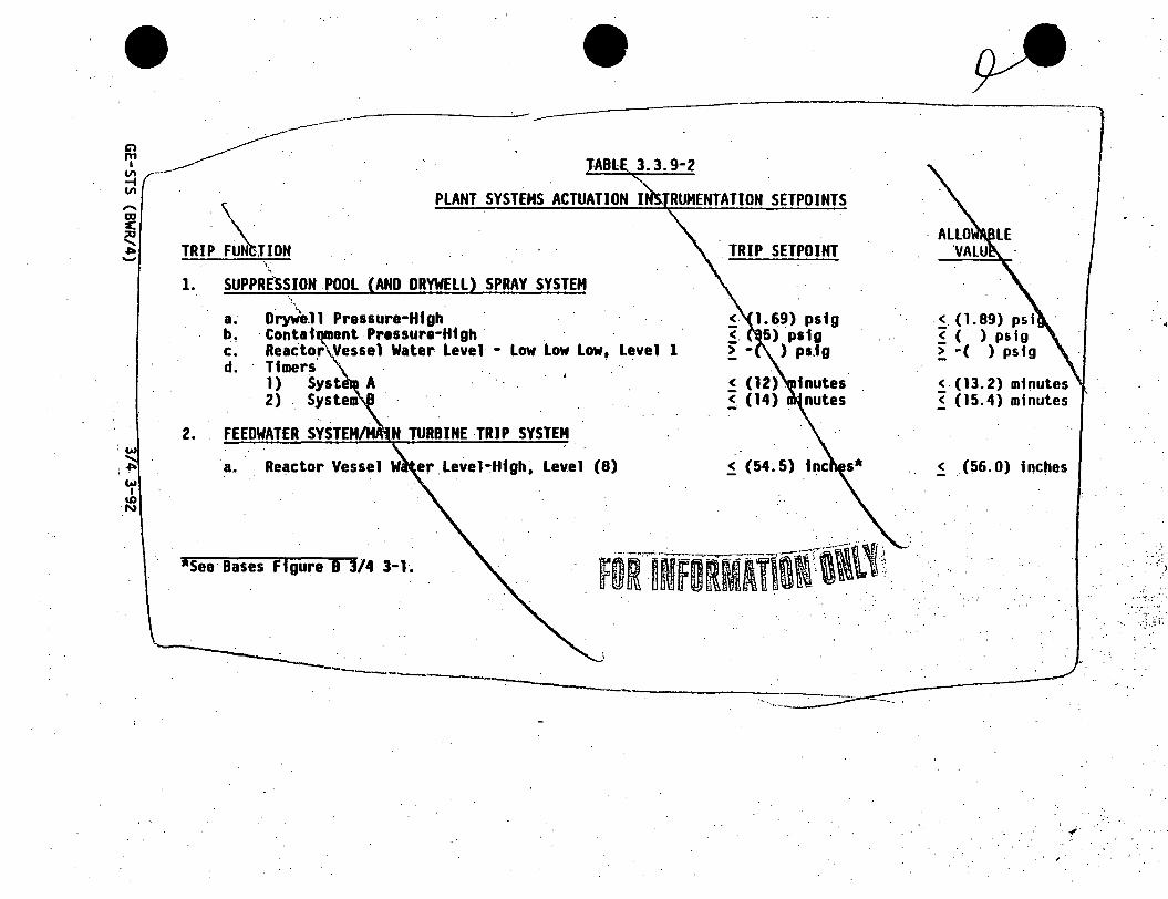
-----------~---·------
JABlE 3.3.9-2
""'
TRIP ~JION PLANT SYSTEMS ACTUATION I
. ~\
1. SUPPRESSION POOL (AND ORYWELL) SPRAY SYSTEM ·,
. ·~\,. .
a. Dryw'e.11 Pressure-High b~ · Contat ant Pressure·Htgh c. Reactor Vessel Water Level - Low Low Low, Level 1 d. Timers
1) Syst A 2) . System
2. .N TURBINE ·TRIP SYSTEM
a. Reactor Vessel W er Level·High~ Lev.el (8)
1see· Bases Figure a 3/4 3-l.
.TRIP SETPOINT
~ (54~5)
< (1.89) psi ~ ( ) psig ~ -( ) psfg
<-(13.2) minutes ~ (15.4) minutes
< (56.0) incties
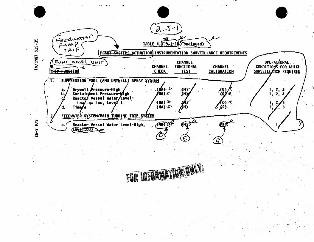
Cl m I
VI ... VI
..... m :c ::0 .......
. .,.. -
w ........ .,.. w I
ID .w
~ TABLE4.~
CHANNEL · CHANNEL FUNCTIONAL
CHECK TEST
·sPRAY SYSTEM
Drywall re11ure-Hfgh .. Contaf ent Pressure· gh Reacto Vessel Water evel
Lo Lqw Low, Lev 1 . Tfm s .
Reactor Vessel Wa~er Level·Htgh, ~-.. ··· ~-
I {NA)~
{HA):i.>
CHANNEL CALIBRATION
.·~
· .. J ©.·
i.
. <
'..,...
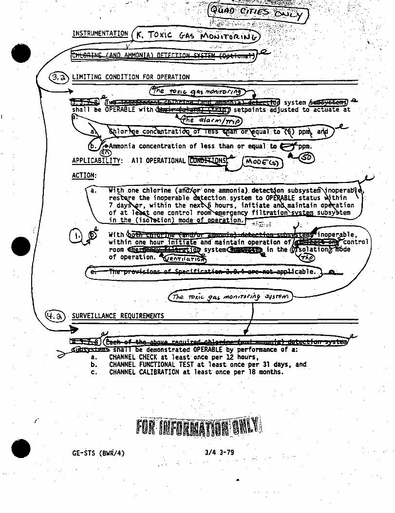
.r . . ·,. .. .-<· .· :,''¢·" ~ .. ~-::'::;'~~:"1";::,.';;~]]f~( .. ,-~·;-~<..:· . .. _' :- · ".~'U4ll ·:<1_it1E5,:.?:'·' -~·"'-' .:·
INSTRUMENTATION ~. TO~iC .· G-As "'M~it,~::~~:·~·;h·~~; .· .,.".-·r·
l§jteRINE (A~D 'MONW pmmoN ;m~~··;g,~;.,:.~w+? . ' ..
® LIMITING CONDITIO.N FOR OPERATION. . . ·: .-~.. .
l'!•e µ1 evi sioA&r of Specificatian. 3i 9aw4 aPe
~·SURVEILLANCE RE UIREMENTS
ti , -z:::&1 ~$'iirs;ys 1 pmQ. s a e demonstrated OPE_RABLE by· performance of a: C? a. CHANNEL CHECK at 1 east once per 12 hours 1
b. CHANNEL FUNCTIONAL TEST at least once·per 31 days~ and c. CHANNEL CALIBRATION at least once per 18 months.
I F0RlifORMATB!ll1~ . ·--·. - . . . . ..... .
GE-STS (BWR/4 ). 3/4 3-79
•


