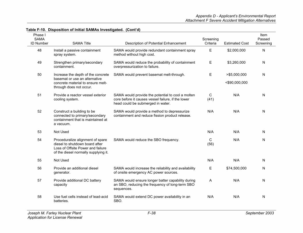
Appendix D - Applicant’s Environmental Report Attachment F Severe Accident Mitigation Alternatives Joseph M. Farley Nuclear Plant September 2003 Application for License Renewal Attachment F Severe Accident Mitigation Alternatives (SAMA)
Transcript
Appendix D - Applicant’s Environmental Report Attachment F Severe Accident Mitigation Alternatives
Joseph M. Farley Nuclear Plant September 2003 Application for License Renewal
Attachment F
Severe Accident Mitigation Alternatives (SAMA)
Appendix D - Applicant’s Environmental Report
Joseph M. Farley Nuclear Plant September 2003 Application for License Renewal
PAGE INTENTIONALLY LEFT BLANK
Appendix D - Applicant’s Environmental Report Attachment F Severe Accident Mitigation Alternatives
Joseph M. Farley Nuclear Plant F-i September 2003 Application for License Renewal
TABLE OF CONTENTS Section Page 1.0 METHODOLOGY.................................................................................................................. F-1
1.1 History of FNP PRA Model ...................................................................................... F-1 1.2 Treatment of External Event Contributors ............................................................... F-2
3.0 DETERMINATION OF PRESENT VALUE FOR THE BASE CASE..................................... F-14 3.1 Offsite Exposure Cost .............................................................................................. F-14 3.2 Offsite Economic Cost.............................................................................................. F-14 3.3 Onsite Exposure Cost .............................................................................................. F-14 3.4 Onsite Cleanup and Decontamination Cost............................................................. F-15 3.5 Replacement Power Cost ........................................................................................ F-16 3.6 Baseline Screening .................................................................................................. F-16 3.7 Sensitivity Analysis................................................................................................... F-17
4.0 PHASE I SAMA CANDIDATES AND SCREENING PROCESS........................................... F-18 5.0 PHASE II SAMA ANALYSIS ................................................................................................. F-19
5.1 SAMA Candidate 7 - Increase Charging Pump Lube Oil Capacity.......................... F-21 5.2 SAMA Candidate 11 - Use Existing Hydro Test Pump for RCP Seal Injection ....... F-22 5.3 SAMA Candidate 24 - Procedures for Actions on Loss of HVAC............................ F-23 5.4 SAMA Candidate 89 - Install Additional Instrumentation for ISLOCAs.................... F-24 5.5 SAMA Candidate 96 - Add Redundant and Diverse Limit Switches to Each
Containment Isolation Valve .................................................................................... F-25 5.6 SAMA Candidate 101 - Install a Digital Feedwater Upgrade................................... F-26 5.7 SAMA Candidate 117 - Leak-tight Enclosure for Fire Protection Piping in Unit 1
Cable Spreading Room............................................................................................ F-27 5.8 SAMA Candidate 118 - Improve Reliability of Fire Protection Clapper Valves in
the Cable Spreading Room...................................................................................... F-28 5.9 SAMA Candidate 119 - Add SW Low Flow Alarms for Critical Room Coolers
(AFW, Charging, RHR & CS)................................................................................... F-29 5.10 SAMA Candidate 120 - Seal Electrical Cabinets in Cable Spreading Room to
Prevent Water Intrusion during Room Flooding....................................................... F-30 5.11 SAMA Candidate 123 - Install Pressure Sensor between RHR Isolation MOVs to
Appendix D - Applicant’s Environmental Report Attachment F Severe Accident Mitigation Alternatives
Joseph M. Farley Nuclear Plant F-ii September 2003 Application for License Renewal
TABLE OF CONTENTS (Continued)
List of Tables Table Page F-1 Year 1990 Population within 50 Miles of FNP ...................................................................... F-8 F-2 Year 2000 Population within 50 Miles of FNP ...................................................................... F-9 F-3 Annualized Population Growth/Loss Rates between 1990 and 2000 for Sectors within
50 Miles of FNP..................................................................................................................... F-10 F-4 Projected Year 2041 Population within 50 Miles of FNP ...................................................... F-11 F-5 Estimated FNP Core Inventory ............................................................................................. F-12 F-6 Accident Sequence Frequencies .......................................................................................... F-12 F-7 MACCS Release Categories vs. FNP Release Categories.................................................. F-13 F-8 General Emergency Declaration Times (hours from reactor trip)......................................... F-13 F-9 Results of FNP Level 3 PRA Analysis (Annual Risk)............................................................ F-13 F-10 Disposition of Initial SAMAs Investigated.............................................................................. F-32 F-11 Summary of Phase II SAMA Analyses.................................................................................. F-47
Appendix D - Applicant’s Environmental Report Attachment F Severe Accident Mitigation Alternatives
Joseph M. Farley Nuclear Plant F-1 September 2003 Application for License Renewal
1.0 METHODOLOGY
The methodology selected for this analysis involves identifying those SAMA candidates that have the most potential for reducing core damage frequency and person-rem risk. The phased approach consists of:
• Extending the FNP PRA/IPE results to a Level 3 analysis by determining off-site dose and economic baseline risk value,
• Determining the maximum averted risk that is possible based on the FNP baseline risk,
• Identifying potential SAMA candidates based on NRC and industry documents,
• Screening out potential SAMA candidates that are not applicable to the FNP design or are of low benefit in Pressurized Water Reactors (PWRs),
• Screening out SAMA candidates whose estimated cost exceeds the maximum possible averted risk, and
• Performing a more detailed cost estimate and Level 3 dose and economic risk evaluation of remaining candidates to see if any have a benefit in risk aversion that exceeds the expected cost.
1.1 HISTORY OF FNP PRA MODEL
Southern Nuclear Operating Company (SNC) conducted a full-scope Level 2 Probabilistic Risk Assessment (PRA) in response to the requirements of the U.S. Nuclear Regulatory Commission (NRC) Generic Letter 88-20 (Reference 1 ) and Supplements 1 and 2 (Reference 2 ). SNC's approach to the Individual Plant Examination (IPE) was to perform a realistic evaluation of FNP's anticipated response to severe accidents. The FNP IPE was performed with the purpose of supporting an objective decision-making process by senior management aimed at maintaining an adequate level of safety to protect against risks associated with postulated severe accidents. The entire IPE analysis process was thoroughly documented and is scrutable.
The IPE was conducted using standard systems analysis practices such as those outlined in NUREG/CR-2300, “PRA Procedures Guide – A Guide to the Performance of Probabilistic Risk Assessments for Nuclear Power Plants” (Reference 3 ) and NUREG/CR-2815, “Probabilistic Safety Analysis Procedures Guide” (Reference 4 ). However, innovative techniques were developed for several areas of the analyses. The traditional event tree analysis and containment analysis portions of the PRA were integrated through the use of plant response trees (PRTs) that depict the combinations of events and model the plant behavior from the initiating event to an end state characterized by retention of fission products within the containment boundary or release to the environment. The accident sequence and containment response code, Modular Accident Analysis Program (MAAP) (Reference 5 ), was utilized to characterize success criteria, timing, and containment response.
The Back-End Analysis involved analyzing representative sequences to determine the timing and nature of any radionuclide releases to the environment. This task required gathering information relative to the FNP containment design, modeling the response of the containment systems, assessing the impact of phenomena controlling severe accident progression, and modeling the mechanistic processes that control the transport of fission products within the containment boundary.
The models developed in the IPE represented the as-built, as-operated, as-maintained FNP as of May 1, 1991, with some exceptions that were explicitly cited throughout the IPE Submittal Report. Care was taken to ensure that only formal procedures in which the operators are trained were credited. The value of equipment or procedural improvements was investigated through sensitivity studies.
Appendix D - Applicant’s Environmental Report Attachment F Severe Accident Mitigation Alternatives
Joseph M. Farley Nuclear Plant F-2 September 2003 Application for License Renewal
Subsequent to the IPE, the FNP PRA model was converted from the Large Event Tree methodology based on the Westinghouse GRAFTER and WESCUT computer codes to a Linked Fault Tree methodology based on the Electric Power Research Institute (EPRI) Computer Aided Fault Tree Analysis (CAFTA) computer code suite. This conversion was completed in March 1998 and the resulting model was designated as Revision 1 of the FNP PRA. Revision 1 updated plant design features to represent the as-built, as-operated, as-maintained FNP as of 12/31/1997. The data and HRA analysis used in Revision 1 continued to be based on the IPE analysis. This revision is documented in the FNP CAFTA Conversion Project notebooks and SNC Technical Services Calculation PSA-F-98-003 (Reference 6 ).
Revision 2 of the FNP PRA was issued in May 1998. This revision continued the refinement of the CAFTA Linked Fault Tree model and incorporated a new accident sequence event tree for Loss of RCP Seal Cooling. This new event tree structure changed the way RCP Seal LOCA sequences were quantified by binning these events into either a general transient mitigation model for leakage rates less than 21 gpm per pump or into a Small LOCA mitigation model for leakage rates greater than 21 gpm per pump. The data and HRA analysis used in Revision 2 continued to be based on the IPE analysis. Revision 2 is documented in SNC Technical Services Calculation PSA-F-98-004 (Reference 7 ).
Revision 3 of the FNP PRA was issued in August 1999. This revision continued the refinement of the CAFTA Linked Fault Tree model and incorporated plant design changes through May 1999. The initiating event and component reliability data used in Revision 3 were based on plant data collected through December 31, 1997 as documented in SNC Technical Services Calculation PSA-F-99-007 (Reference 8 ). The initiating event analysis for Revision 3 was also updated to be consistent with the initiating event categories in NUREG/CR-5750, “Rates of Initiating Events at U.S. Nuclear Power Plants: 1987-1995” (Reference 9 ). In addition, new event tree models for SBO and Anticipated Transient Without Trip (ATWT) were incorporated. Revision 3 is documented in SNC Technical Services Calculation PSA-F-99-010 (Reference 10 ).
Revision 4 of the FNP PRA was issued in May 2000. This revision included model enhancements to more effectively use the FORTE quantification code, revised HRA analysis for several events where procedural changes had occurred (SNC Technical Services Calculation PSA-F-00-00115), revised flooding analysis for the CCW heat exchanger/pump room and the Service Water Intake Structure (SNC Technical Services Calculation PSA-F-00-00216), and new system models for the emergency air system and the Unit 2 Service Water Pump Lube and Cooling system. Revision 4 is documented in SNC Technical Services Calculation PSA-F-00-009 (Reference 11 ).
A minor update to modify the flag events used to designate the running status of Instrument Air Compressors was issued as Revision 4a in September 2000. This change did not affect the baseline quantification results, but added flexibility to the model needed for the Equipment Out Of Service (EOOS) application used in work planning. Revision 4a is documented in SNC Technical Services Calculation PSA-F-00-019 (Reference 12 ).
Revision 5 of the FNP PRA was issued in November 2001. This revision included model changes to address comments from the WOG PRA Peer Review conducted in August 2001 and incorporated plant design changes completed or planned for completion through the Unit 1 17th refueling outage. Revision 5 is documented in SNC Technical Services Calculation PSA-F-01-017 (Reference 13 ).
1.2 TREATMENT OF EXTERNAL EVENT CONTRIBUTORS
The contribution from external events was treated by doubling the internal events contribution. This sufficiently bounds the risk from external events for the following reasons:
• The FNP IPEEE found that containment response to core damage external events was similar to that from the internal events in the IPE. The FNP IPEEE found no external events vulnerabilities in terms of containment bypass or isolation failure, so an internal events profile can be used to bound the offsite consequences.
Appendix D - Applicant’s Environmental Report Attachment F Severe Accident Mitigation Alternatives
Joseph M. Farley Nuclear Plant F-3 September 2003 Application for License Renewal
• Modifications have been completed to improve equipment response to seismic events as a result of insights from the IPEEE.
• Modifications have been made to improve tornado missile protection for several yard structures at FNP since the completion of the IPEEE.
• Modifications are planned to eliminate dependence on Kaowool barriers for Appendix R compliance. The planned improvements being considered involve a combination of cable re-routes, fire barrier upgrades, analyses to demonstrate the acceptability of the existing condition with no credit for Kaowool, and other measures.
• The CDF calculated in the IPEEE was comparable to the internal events CDF at the time. Since completion of the IPEEE, the FNP internal events PRA has been converted from a large event tree model to a linked fault tree. This and other improvements in model fidelity and plant design have resulted in a reduction of the internal events CDF by a factor of approximately 3. Since the major contributors to CDF from external events are similar to the major contributors to CDF from internal events, and since improvements have been made or are planned to improve plant response to seismic and fire events, a similar or greater reduction would be expected for the external events CDF.
Appendix D - Applicant’s Environmental Report Attachment F Severe Accident Mitigation Alternatives
Joseph M. Farley Nuclear Plant F-4 September 2003 Application for License Renewal
2.0 LEVEL 3 PRA ANALYSIS
The MACCS2 code (Reference 14 ) was used to perform the Level 3 PRA for the FNP. The input parameters given with the MACCS2 “Sample Problem A,” which included the NUREG-1150 food model (Reference 15 ), formed the basis for the present analysis. These generic values were supplemented with parameters specific to FNP and the surrounding area. Site-specific data included population distribution, economic parameters, and agricultural production. Plant-specific release data included the time-activity distribution of nuclide releases and release frequencies. The behavior of the population during a release (evacuation parameters) was based on plant and site-specific set points (i.e., declaration of a General Emergency) and evacuation time estimates (Reference 16 ). These data were used in combination with site and region-specific meteorology to simulate the probability distribution of impact risks (exposure and economic) to the surrounding (within 50 miles) population from the evaluated accident sequences at FNP.
2.1 POPULATION
The collective dose to the public was calculated by considering the population within a 50-mile radius from FNP. A fifty-mile circular area is the standard range used in modeling consequences to the off-site population from an airborne release. The area was divided into 16 pie-shaped wedges, each spanning 22.5-degree angles representing compass directions which start at north and move clockwise through north-northwest. The area was further divided into 10 annular regions, at radii corresponding to 1, 2, 3, 4, 5, 10, 20, 30, 40, and 50 miles from the center. The combination of 10 radial and 16 angular divisions resulted in 160 sectors in which the concentrations were calculated by the airborne dose models.
The population in each of these 160 sectors was calculated using 1990 and 2000 US Census population data as follows:
• Geographical information system (GIS) software was used to create a 160-sector overlay onto a regional map centered at the site coordinates.
• Block-group (BG) population data from the 1990 and 2000 U.S. Census for the 50-mile radius encompassing the site were downloaded to the GIS. These data consist of total populations within the geographic boundaries of each BG.
• The geographic boundaries of each BG were defined in the GIS and overlain onto the sector map. Some sectors contained one or more whole BGs and/or partial BGs. The area that each BG occupied within a sector was calculated and used to estimate the BG’s population contribution to that sector.
• The population in each sector was calculated as the sum of each BG’s population, prorated by the fraction of the BG’s area within that sector.
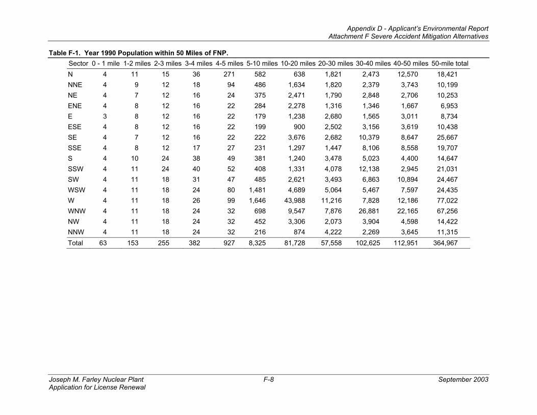
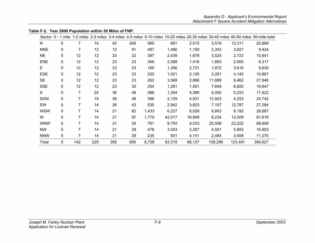
Tables F-1 and F-2 list the population for the years 1990 and 2000, respectively, in each of the 160 sectors, as well as the radial totals, directional totals and grand totals for the entire 50-mile radius. A constant population growth/loss rate model, based on the year 1990 and year 2000 population changes in each sector, was applied to project the population to the year 2041. This model consists of calculating the rate of population growth or loss – dividing the year 2000 population by the year 1990 population in each sector – and assuming this growth or loss rate will remain constant over the projected period. Table F-3 lists the annualized population growth or loss rate for each sector based on the changes in population between 1990 and 2000. For the year 2041 projection, the decennial growth or loss in a sector’s population was raised to the power of 4.1 (the 41-year difference between 2041 and 2000, divided by 10 years). The resulting scaling factor was applied to the sector’s year 2000 population. For example, if a sector’s population decreased from 100 to 90 people between 1990 and 2000, the resulting ratio of 0.90 was raised to the power of 4.1. This scaling factor of 0.65 was applied to the year 2000 population of 90 in that sector, to obtain a year 2041 projection of 58. Alternatively, if the population increased from 100 to 110, the resulting ratio of 1.1 raised to the power of 4.1 would give a scaling factor
Appendix D - Applicant’s Environmental Report Attachment F Severe Accident Mitigation Alternatives
Joseph M. Farley Nuclear Plant F-5 September 2003 Application for License Renewal
of 1.48. Multiplying the year 2000 population of 110 by 1.48 results in a year 2041 projection of 163. Table F-4 lists the population projected to the year 2041 for the 50-mile radius around FNP.
The population projection approach used here is more conservative (that is, it will likely overestimate future populations) than a constant linear growth or loss model. In a constant linear growth/loss model, the number of people added to, or lost from, each sector between 1990 and 2000 is first calculated. The net change in population between 1990 and 2000 is then multiplied by 4.1 to estimate the net change in population that may occur between 2000 and 2041. That net change (positive for population growth, negative for population loss) is added to the year 2000 population for that sector. This approach yields a lower population growth than the constant growth rate model, and sometimes results in negative population values for those sectors in which a large fraction of the population was lost between the years 1990 and 2000.
2.2 ECONOMY
MACCS2 requires the spatial distribution of certain economic data (fraction of land devoted to farming, annual farm sales, fraction of farm sales resulting from dairy production, and property value of farm and non-farm land) in the same manner as the population. This was done by specifying the data for each of the 28 counties surrounding the plant, to a distance of 50 miles. The values used for each of the 160 sectors were obtained from the data corresponding to the counties which made up more than 2/3rd of the area in their sectors. For 34 sectors, no county encompassed more than 2/3rd of the area, so data, weighted by the fraction of each county in that sector, was defined.
In addition, generic economic data that are applied to the region as a whole were revised from the MACCS2 sample problem input when better information was available. These revised parameters include per diem living expenses (applied to owners of interdicted properties and relocated populations), relocation costs (for owners of interdicted properties), value of farm and non-farm wealth, and fraction of farm wealth from improvements (e.g., buildings, equipment).
2.3 AGRICULTURE
Agricultural production information was taken from the 1997 Agricultural Census (Reference 17 ). Production within 50 miles of the site was estimated based on those counties within this radius. Production in those counties which lie partially outside of this area was multiplied by the fraction of the county within the area of interest. Cotton and tobacco, non-foods, were harvested from 24 percent of the croplands within 50 miles of the site. Of the food crops, legumes (26 percent of total cropland, consisting mainly of peanuts and soybeans) and grain (18 percent, chiefly corn and wheat) were harvested from the largest areas. The total food and commercial harvest consumed approximately 75 percent of the croplands within 50 miles of the site; pasture made up another 15 percent of this land.
The growing seasons’ durations were obtained from Reference 18 , when available. Reference 19 was used as a secondary source.
2.4 NUCLIDE RELEASE
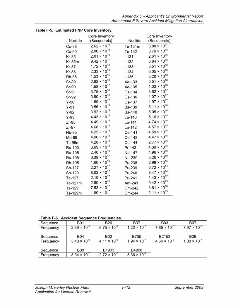
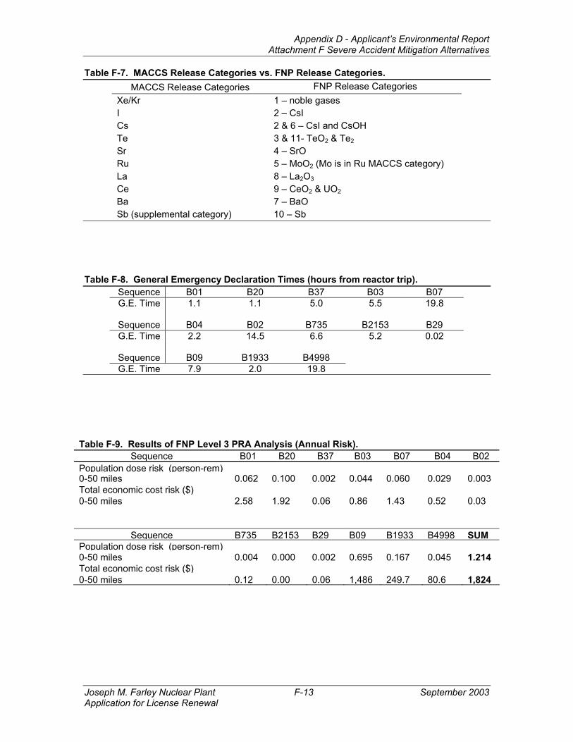
The core inventory at the time of the accident was based on the input supplied in the MACCS User’s Guide (Reference 14 ). The core inventory corresponds to the end-of-cycle values for a 3412-MWth PWR plant. A scaling factor of 0.813 was used to provide a representative core inventory of 2775-MWth at FNP. Table F-5 gives the estimated FNP core inventory. Release frequencies, shown in Table F-6, and nuclide release fractions (of the core inventory) were analyzed to determine the sum of the exposure (50-mile dose) and economic (50-mile economic costs) risks from 13 accident sequences (also given in Table F-6). Each accident frequency was chosen to represent the set of similar accidents. FNP nuclide release categories were related to the MACCS categories as shown in Table F-7. Multiple release duration periods were defined which represented the time distribution of each category’s releases.
Appendix D - Applicant’s Environmental Report Attachment F Severe Accident Mitigation Alternatives
Joseph M. Farley Nuclear Plant F-6 September 2003 Application for License Renewal
The reactor building has a diameter of 137.5 feet and a height of 135.75 feet. All releases were modeled as occurring at ground level. The thermal content of each of the releases was conservatively assumed to be the same as ambient, i.e., buoyant plume rise was not modeled.
2.5 EVACUATION
Reactor trip for each sequence was taken as time zero relative to the core containment response times. A General Emergency is declared when plant conditions degrade to the point where it is judged that there is a credible risk to the public; it was assumed here that the declaration would coincide with the onset of core melt. Table F-8 shows the resulting declaration times.
The MACCS2 User’s Guide input parameters of 95 percent of the population within 10 miles of the plant (Emergency Planning Zone) evacuating and 5 percent not evacuating were employed. These values have been used in similar studies (e.g., References 20 and 21) and are conservative relative to the NUREG-1150 study, which assumed evacuation of 99.5 percent of the population within the Emergency Planning Zone (Reference 15 ). The evacuees are assumed to begin evacuation 30 minutes (Reference 16) after a general emergency has been declared and are evacuated at a radial speed of 0.65 meters/sec. This speed is derived from the minimum speed from any evacuation zone under adverse conditions. As such, it encompasses not only adverse traffic and weather conditions, but also that some evacuees will begin evacuating at times later than 30 minutes.
2.6 METEOROLOGY
Annual meteorology data sets from 1998 through 2000 were investigated for use in MACCS2. The 1998 data set was found to result in the largest doses and was subsequently used to create the one-year sequential hourly data set used in MACCS2. The conditional dose from each of the other years was within 10 percent of the chosen year. Onsite wind speed and direction from the 35-foot sensor were combined with atmospheric stability (specified according to the vertical temperature gradient as measured between the 200-foot and 35-foot levels). Hourly stability was classified according to the scheme used by the NRC (Reference 22 ).
National Weather Service (NWS) precipitation measurements at Dannelly Field in Montgomery, Alabama, were used in the simulation. This location was the closest to the FNP site having a complete set of hourly precipitation for the time period of interest (1998-2000). A complete onsite data set for the year 1998 was available; substitution of the latter for the NWS data resulted in a decrease in dose and economic risk of 2 percent. Inspection of annual precipitation quantities (Reference 23 ) indicated that 1998 was a year with historically low precipitation. The effect of a greater precipitation rate was investigated by multiplying the 1998 hourly precipitation data set by the ratio (1.42) of the annual quantities from 1996 (a recent year of high precipitation) and 1998; the result was a decrease in risk of less than 2 percent.
Atmospheric mixing heights were specified for AM and PM hours. These values were taken as 500 and 1400 meters, respectively (Reference 24 ).
2.7 MACCS2 RESULTS
The resulting annual risk from the analyzed FNP releases is provided in Table F-9.
The largest risk is from sequence B09 (representing bin 11). Almost all of the noble gases, iodine, and cesium (as well as much of the other release categories) are released shortly after a general emergency is declared for this sequence. As such, it represents close to a bounding accident scenario. Any scenario (e.g., beyond design basis external event initiators) not encompassed by the sequences analyzed here would be expected to have impacts (i.e., dose and costs) not significantly greater than B09. Although the risk from this sequence is ameliorated by its relatively small frequency of occurrence, beyond design basis external events will likely have similar frequencies.
Appendix D - Applicant’s Environmental Report Attachment F Severe Accident Mitigation Alternatives
Joseph M. Farley Nuclear Plant F-7 September 2003 Application for License Renewal
MACCS2 calculated the annual baseline population dose risk within 50 miles at 1.214 person-rem. The total annual economic risk was calculated at $1,824. These values apply to Unit 1 and are assumed to apply to Unit 2 due to the similar results obtained in the Level 1 and Level 2 PSA models for the two units.
Appendix D - Applicant’s Environmental Report Attachment F Severe Accident Mitigation Alternatives
Joseph M. Farley Nuclear Plant F-8 September 2003 Application for License Renewal
Appendix D - Applicant’s Environmental Report Attachment F Severe Accident Mitigation Alternatives
Joseph M. Farley Nuclear Plant F-14 September 2003 Application for License Renewal
3.0 DETERMINATION OF PRESENT VALUE FOR THE BASE CASE
This section explains how SNC calculated the monetized value of the status quo (i.e., accident consequences without SAMA implementation). SNC also used this analysis to establish the maximum benefit that a SAMA could achieve if it eliminated all FNP risk.
3.1 OFFSITE EXPOSURE COST
The baseline annual offsite exposure risk was converted to dollars using the NRC’s conversion factor of $2,000 per person-rem (Reference 25, Section 5.7.1.2), and discounting to present value using the NRC standard formula (Reference 25, Section 5.7.1.3):
Wpha = C x Zpha
Where: Wpha = monetary value of public health risk after discounting C = [1-exp(-rtf)]/r Tf = years remaining until end of facility life = 20 years r = real discount rate (as fraction) = 0.07/year Zpha = monetary value of public health (accident) risk per year before discounting
($/year)
The Level 3 analysis showed an annual offsite population dose risk of 1.214 person-rem. The calculated value for C using 20 years and a 7 percent discount rate is approximately 10.76. Therefore, calculating the discounted monetary equivalent of accident risk involves multiplying the dose (person-rem per year) by $2,000 and by the C value (10.76). The calculated offsite exposure cost is $26,123.
3.2 OFFSITE ECONOMIC COST
The Level 3 analysis showed an annual offsite economic risk of $1,824. Calculated values for offsite economic costs caused by severe accidents must be discounted to present value as well. This is performed in the same manner as for public health risks and uses the same C value. The resulting value is $19,633.
3.3 ONSITE EXPOSURE COST
SNC evaluated occupational health using the NRC methodology in Reference 25, Section 5.7.3, which involves separately evaluating “immediate” and long-term doses.
Immediate Dose - For the case where the plant is in operation, the equation that NRC recommends using (Reference 25, Sections 5.7.3 and 5.7.3.3) is:
Equation 1:
WIO = R{(FDIO)S -(FDIO)A} {[1 - exp(-rtf)]/r}
Where: WIO =monetary value of accident risk avoided due to immediate doses, after discounting R = monetary equivalent of unit dose ($/person-rem) F = accident frequency (events/yr) DIO = immediate occupational dose (person-rem/event) S = subscript denoting status quo (current conditions) A = superscript denoting after implementation of proposed action
Appendix D - Applicant’s Environmental Report Attachment F Severe Accident Mitigation Alternatives
Joseph M. Farley Nuclear Plant F-15 September 2003 Application for License Renewal
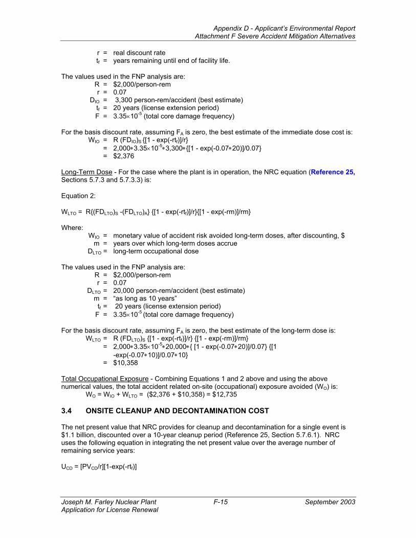
r = real discount rate tf = years remaining until end of facility life.
The values used in the FNP analysis are: R = $2,000/person-rem r = 0.07 DIO = 3,300 person-rem/accident (best estimate) tf = 20 years (license extension period) F = 3.35×10⁻⁵ (total core damage frequency)
For the basis discount rate, assuming FA is zero, the best estimate of the immediate dose cost is: WIO = R (FDIO)S {[1 - exp(-rtf)]/r} = 2,000∗3.35×10-5∗3,300∗{[1 - exp(-0.07∗20)]/0.07} = $2,376
Long-Term Dose - For the case where the plant is in operation, the NRC equation (Reference 25, Sections 5.7.3 and 5.7.3.3) is:
Where: WIO = monetary value of accident risk avoided long-term doses, after discounting, $ m = years over which long-term doses accrue DLTO = long-term occupational dose
The values used in the FNP analysis are: R = $2,000/person-rem r = 0.07 DLTO = 20,000 person-rem/accident (best estimate) m = “as long as 10 years” tf = 20 years (license extension period) F = 3.35×10⁻⁵ (total core damage frequency)
For the basis discount rate, assuming FA is zero, the best estimate of the long-term dose is: WLTO = R (FDLTO)S {[1 - exp(-rtf)]/r} {[1 - exp(-rm)]/rm} = 2,000∗3.35×10-5∗20,000∗{ [1 - exp(-0.07∗20)]/0.07} {[1 -exp(-0.07∗10)]/0.07∗10} = $10,358
Total Occupational Exposure - Combining Equations 1 and 2 above and using the above numerical values, the total accident related on-site (occupational) exposure avoided (WO) is:
WO = WIO + WLTO = ($2,376 + $10,358) = $12,735
3.4 ONSITE CLEANUP AND DECONTAMINATION COST
The net present value that NRC provides for cleanup and decontamination for a single event is $1.1 billion, discounted over a 10-year cleanup period (Reference 25, Section 5.7.6.1). NRC uses the following equation in integrating the net present value over the average number of remaining service years:
UCD = [PVCD/r][1-exp(-rtf)]
Appendix D - Applicant’s Environmental Report Attachment F Severe Accident Mitigation Alternatives
Joseph M. Farley Nuclear Plant F-16 September 2003 Application for License Renewal
Where: PVCD = Net present value of a single event r = real discount rate tf = years remaining until end of facility life.
The values used in the FNP analysis are: PVCD = $1.1×10⁹ r = 0.07 tf = 20
The resulting net present value of cleanup integrated over the license renewal term, $1.18×10¹⁰, must be multiplied by the total core damage frequency of 3.35×10⁻⁵ to determine the expected value of cleanup and decontamination costs. The resulting monetary equivalent is $396,083.
3.5 REPLACEMENT POWER COST
Long-term replacement power costs were determined following the NRC methodology in Reference 25, (Section 5.7.6.2). The net present value of replacement power for a single event, PVRP, was determined using the following equation:
PVRP = [$1.2×10⁸/r] * [1 - exp(-rtf)]2
Where: PVRP = net present value of replacement power for a single event, ($) R = 0.07 tf = 20 years (license renewal period)
To attain a summation of the single-event costs over the entire license renewal period, the following equation is used:
URP = [PVRP /r] * [1 - exp(-rtf)]2
Where: URP = net present value of replacement power over life of facility ($-year)
After applying a correction factor to account for FNP Unit 1’s size relative to the “generic” reactor described in Reference 25 (i.e., 852 MWe/910 MWe), the replacement power costs are determined to be 7.39×10⁹ ($-year). Multiplying this value by the CDF (3.35×10⁻⁵) results in a replacement power cost of $247,148.
3.6 BASELINE SCREENING
The sum of the baseline costs is as follows: Offsite exposure cost = $26,123 Offsite economic cost = $19,633 Onsite exposure cost = $12,735 Onsite cleanup cost = $396,083 Replacement Power cost = $247,148 Total cost = $701,722
SNC doubled this value to account for external events contributors to the CDF and rounded this value up to $1,400,000 to use in screening out SAMAs as economically infeasible; if the estimated cost of implementing a SAMA exceeded $1,400,000, SNC discarded it from further analysis. Exceeding this threshold would mean that a SAMA could not have a positive net value even if it could eliminate all severe accident costs.
Appendix D - Applicant’s Environmental Report Attachment F Severe Accident Mitigation Alternatives
Joseph M. Farley Nuclear Plant F-17 September 2003 Application for License Renewal
3.7 SENSITIVITY ANALYSIS
A sensitivity analysis was performed by changing the real discount rate from seven to three percent. This had the effect of increasing the baseline cost-risk to $811,190. This change in the discount rate did not affect the number of SAMAs that were retained for further analysis.
Appendix D - Applicant’s Environmental Report Attachment F Severe Accident Mitigation Alternatives
Joseph M. Farley Nuclear Plant F-18 September 2003 Application for License Renewal
4.0 PHASE I SAMA CANDIDATES AND SCREENING PROCESS
An initial list of 128 SAMA candidates (including 3 variants – 5A, 35A, and 63A) was developed from lists of Severe Accident Mitigation Design Alternatives at other nuclear power plants, NRC documents, and documents related to advanced power reactor designs. This initial list was then screened to remove those that were not applicable to the FNP plant due to design differences.
Twenty-eight of the initial 128 candidate SAMAs were removed from further consideration as they did not apply to the design used at FNP. Another 30 SAMA candidates have already been addressed in the existing FNP design and were thus dropped from further consideration. Seventeen procedural SAMA candidates were found that had already been addressed in FNP’s procedures and/or training program and were also dropped from further consideration. Thirteen SAMA candidates were of sufficient similarity to other SAMA candidates that they were either combined or dropped from further consideration.
This left 40 unique SAMA candidates that were applicable to FNP and were of potential value in averting the risk of severe accidents. A preliminary cost estimate was prepared for each of these candidates to focus on those that had the possibility of having a net positive benefit and to eliminate those whose costs were clearly beyond the possibility of any corresponding benefit.
When the screening cutoff of $1,400,000 (Section 3.6 ) was applied, 25 candidates were eliminated that were more expensive than any possible off-setting benefit. This left 15 candidates for further analysis.
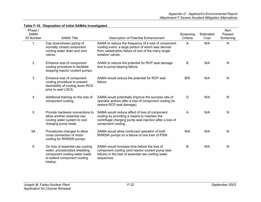
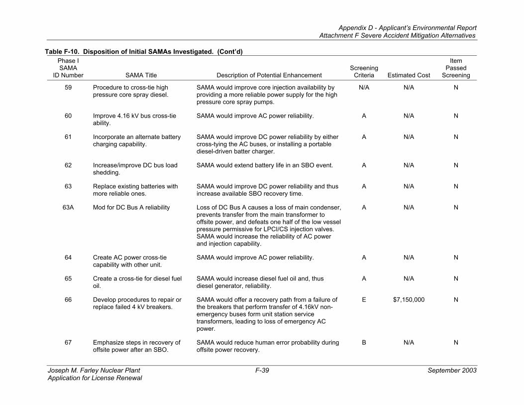
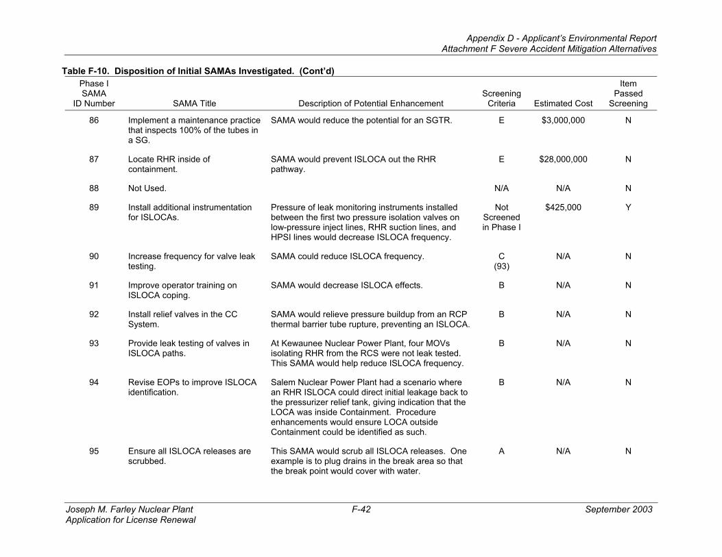
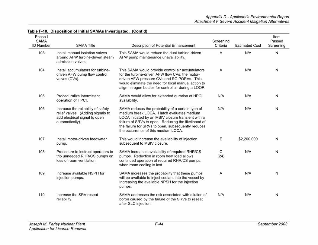
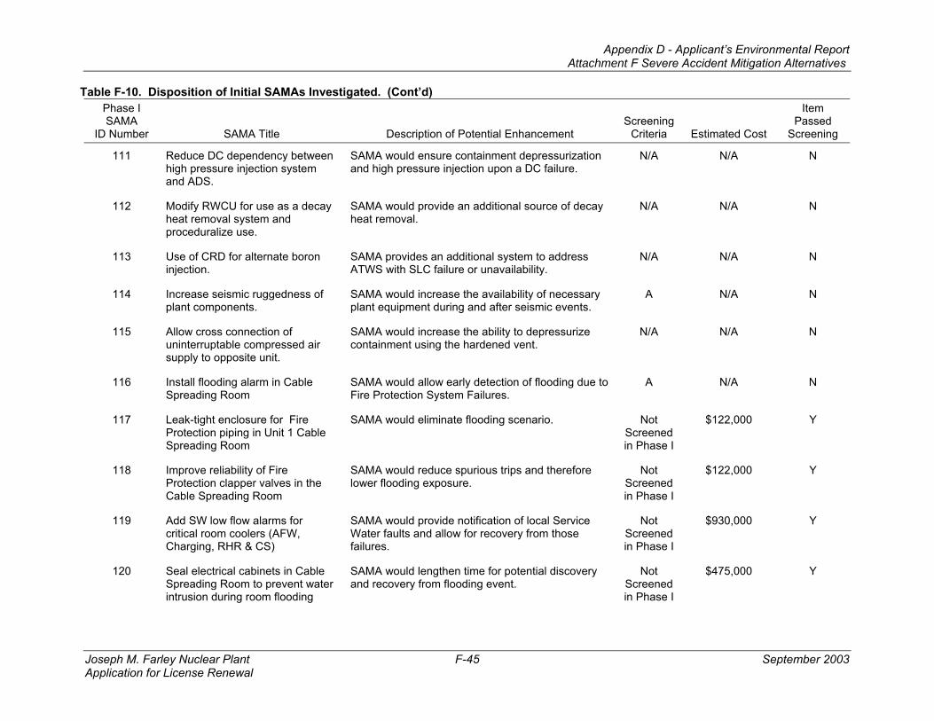
Table F-10 shows the disposition of the initial set of candidate SAMAs, including an indication of the screening criterion that was applicable for those candidate SAMAs that were removed from further consideration.
Appendix D - Applicant’s Environmental Report Attachment F Severe Accident Mitigation Alternatives
Joseph M. Farley Nuclear Plant F-19 September 2003 Application for License Renewal
5.0 PHASE II SAMA ANALYSIS
For each of the 15 remaining SAMA candidates, a more detailed conceptual design was prepared along with a more detailed estimated cost. This information was then used to evaluate the effect of the candidate changes upon the plant safety model.
During the Phase II analysis, it was determined that two of the SAMA candidates (numbers 102 and 125 in Table F-10 ) would not contribute to a significant reduction in the CDF and where very expensive ($1,000,000 each). These two SAMAs were subsequently excluded from a more detailed analysis. Another two SAMAs (numbers 41 and 46 in Table F-10) were determined to mitigate only the post core-damage release of radionuclides, but would not contribute to reducing the CDF itself. Their estimated costs, $900,000 and $450,000, respectively, greatly exceed the maximum attainable benefit from avoiding off-site releases (see Sections 3.1 and 3.2), which would not exceed $46,000. Therefore, these two SAMA candidates were further removed from detailed analysis.
Some of the remaining SAMAs were grouped to reflect similarities in modeling their implementation. The next step in the evaluation of these SAMAs was to develop a PRA model for each of the groups. This model was used to determine the change in CDF that could occur if the SAMA candidate were to be implemented. Since the implementation for these potential modifications has not been designed, a bounding approach to the analyses was used. Such a bounding model typically assumes the change is “perfect” in that it removes portions of the model representing failure of the affected portions of the PRA model. This approach gives the upper bound of the impact of the modification and is useful in elimination of candidates if this bounding impact is less than the implementation costs.
To focus cost estimate refinements, it is necessary to translate the change in CDF resulting from analyzing the SAMA candidate PRA model to a benefit in dollars to compare with the implementation cost estimates. For this purpose a bounding estimate of the benefit associated with each of the SAMA analysis cases was developed from the contributions to the maximum benefit that could possibly be attained from plant improvements (Maximum Attainable Benefit, MAB - equivalent to eliminating all risk due to the presence of the plant).
The MAB is made up on several contributions, as described in Section 3.0:
The first two of these contributions are directly calculated in the Level 3 PRA analysis. The last three are calculated in accordance with methods published by the NRC and are proportional to core damage frequency.
Therefore, the estimate of the benefit for each SAMA sensitivity was made by determining the change in CDF between the current (baseline) model and that resulting from a model changed to represent the plant after implementation of a modification suggested by the SAMA. This change in CDF was used to estimate the change in the contribution to the last three cost contributors. The offsite costs were estimated by applying any changes from the baseline accident sequence frequencies (Table F-6 ) to the offsite dose and economic cost impacts evaluated in the Level 3 PRA model.
Comparing the implementation costs with the estimated benefit allows more of the SAMAs to be eliminated from further consideration. Those SAMAs that have an implementation cost much
Appendix D - Applicant’s Environmental Report Attachment F Severe Accident Mitigation Alternatives
Joseph M. Farley Nuclear Plant F-20 September 2003 Application for License Renewal
greater than the estimated benefit can be screened from further consideration. These SAMAs whose estimated benefits are close to or greater than the expected cost need to be further examined to ensure that the cost estimates are realistic.
A description of the remaining 11 SAMA candidates, the modeling changes that were made, and the results of the cost/benefit calculations, are provided in the following sections. A summary of the Phase II analyses is presented in Table F-11.
Appendix D - Applicant’s Environmental Report Attachment F Severe Accident Mitigation Alternatives
Joseph M. Farley Nuclear Plant F-21 September 2003 Application for License Renewal
SAMA Objective: SAMA would lengthen the time before centrifugal charging pump failure due to lube oil.
Applicability to FNP
The charging pumps perform functions associated with both HHSI and CVCS. The pumps are each located in separate watertight compartments, are seismically qualified, and are designed to perform functions important to safety.
Conceptual Modification
Fabricate a supplemental lube oil reservoir for each charging pump using safety-related piping. A rectangular tank 6” wide x 3’ tall x 4’ long would double the lube oil reservoir capacity. A tank this size could be installed on the wall adjacent to each pump and connected to the existing reservoir with small bore piping. Each new tank (including sight glass & vent, fill and drain valves) would be seismically supported to not affect the seismic qualification of the existing pump. The new reservoir would provide a parallel gravity fed supply source to the lube oil pump suction. The new reservoir would contain oil at the same static head as the existing reservoir. As oil was consumed from the existing system, oil from the supplemental system would allow for the addition of supplemental oil to equalize the static heads between the two reservoirs.
Model Changes: In this SAMA analysis, it is assumed that the charging pumps do not require any cooling (i.e., cooling is perfectly reliable).
The following gates were removed to delete the dependence on oil cooling. Similar changes were made for Cooling to High Head Pumps B and C.
Cooling to High Head Pump A;
Gate HH0070A (input to HH0023A),
Gate HH0070A-SBO (input to HH0023A-SBO),
Gate HHR0070A (input to HHR0023A),
Gate HHR0070A (input to HH0070A),
Gate HHR0070A-SBO (input to HHR0023A-SBO),
Gate HHR0070A-SBO (input to HH0070A-SBO),
Gate SINJ0104 (input to SINJ0099),
Gate SINJ0104 (input to SREC071).
Assumptions Used in Conceptual Modification
Increasing the oil volume in each room would increase the combustible loading. This increase in combustible loading would be addressed by engineering analysis or evaluation and would not require modifications to the plant.
Appendix D - Applicant’s Environmental Report Attachment F Severe Accident Mitigation Alternatives
Joseph M. Farley Nuclear Plant F-22 September 2003 Application for License Renewal
Cost/Benefit Calculation
Estimated Implementation Cost: $270,000/unit
Estimated Reduction in Risk Benefit: $59,621/unit
Estimated Net Benefit: ($210,379/unit)
Sensitivity Analysis
Another case was developed to be more realistic; rather than eliminating the cooling dependency, in this case a “recovery potential” was modeled (event SAMA-CHG-OILCLG), which was ANDed with the existing dependency and the new event was assigned a value of 0.2. This event was ANDed with each of the gates listed above. This case resulted in a reduction in risk benefit of $45,904 and a net benefit of -$224,096.
Conclusion
A large negative net benefit was determined for both cases, and even doubling the estimated reduction in risk benefit to account for external event contributors to the CDF would not be large enough to offset the cost of implementing this SAMA. Therefore, implementation of this SAMA would not be cost beneficial.
5.2 SAMA CANDIDATE 11 - USE EXISTING HYDRO TEST PUMP FOR RCP SEAL INJECTION
SAMA Objective: SAMA would provide an independent seal injection source, without the cost of a new system.
Applicability to FNP
RCP seal injection is performed by the charging pumps. The charging pumps take suction from the RWST during emergency conditions. The hydro test pump also takes suction from the RWST. Therefore this SAMA would provide another prime mover of the cooling medium but not an independent cooling medium.
Conceptual Modification
For this SAMA to be effective at FNP, an alternate source of seal injection would have to be established in less than 15 minutes. Process connections would be required in the hydro test pump discharge and the RCP seal injection line, upstream of the split to supply each pump. The hydro test pump suction isolation valve would be replaced with an MOV. An MOV would be installed in the new line from the hydro test pump to the seal injection line and an MOV would be required in the seal injection line, upstream of the new process connection. All of these new MOVs would be safety-related. Additionally, the power supply to the hydro test pump would have to be changed to a class 1E supply.
Model Changes: The model represents improvement in the recovery potential for CCW through improved procedures and/or additional seal injection alternatives.
(1) Added an event under Gate #GENTRA-RCP-SC called SAMA-CCWREC-SENS to represent the probability of failure of use of another system that could provide seal injection.
(2) Set value to 0.1.
Appendix D - Applicant’s Environmental Report Attachment F Severe Accident Mitigation Alternatives
Joseph M. Farley Nuclear Plant F-23 September 2003 Application for License Renewal
Assumptions Used in Conceptual Modification
Seal injection flow from the hydro test pump can leave the pump through the normal seal return flow path.
Cost/Benefit Calculation
Estimated Implementation Cost: $520,000/unit
Estimated Reduction in Risk Benefit: $229,028/unit
Estimated Net Benefit: ($290,972/unit)
Conclusion
A large negative net benefit was determined for this SAMA, and even doubling the estimated reduction in risk benefit to account for external event contributors to the CDF would not be large enough to offset the cost of implementing this SAMA. Therefore, implementation of this SAMA would not be cost beneficial.
5.3 SAMA CANDIDATE 24 - PROCEDURES FOR ACTIONS ON LOSS OF HVAC
SAMA Objective: SAMA would provide for improved credit to be taken for loss of HVAC sequences (improved affected electrical equipment reliability upon a loss of Control Building HVAC).
Applicability to FNP
A review of FNP procedures did not locate specific procedures to accomplish the objective of this SAMA. Therefore this SAMA is applicable to FNP.
Conceptual Modification
For this SAMA to be effective at FNP, remote indication of room temperature would be required so that operators would know when to take action. This would require installation of temperature sensors in the following pump rooms: Charging, RHR, Containment Spray, Auxiliary Feedwater and Component Cooling. Control circuits would be designed to generate an alarm in the main control room when room temperatures exceeded the design limit. The existing fan trouble alarm annunciator for each room could be used to alarm the over-temperature condition. This would require re-labeling of the annunciator window and procedure revisions to instruct operators to perform actions to mitigate the effects of a loss of HVAC. All components including the new temperature sensors, conduit & cabling, relays, etc. would be safety related.
Model Changes: The SAMA analysis models (one for each system requiring room cooling) represent the bounding case for each system in which it is assumed that the room cooling is perfect (cannot fail, i.e., removed from the model).
Auxiliary Feedwater Dependence on Room Cooling: Train A MDAFW pump room cooling is modeled in gate HVAC-AFWA (input to AFW-0048) and HVAC-AFWA-SL (input to AFW-0048-SL). These HVAC gates were removed in this model to delete the dependence on HVAC.
Train B MDAFW pump room cooling is modeled in gate HVAC-AFWB (input to AFW-0113) and HVAC-AFWB-SL (input to AFW-0113-SL). These HVAC gates were removed in this model to delete the dependence on HVAC.
Appendix D - Applicant’s Environmental Report Attachment F Severe Accident Mitigation Alternatives
Joseph M. Farley Nuclear Plant F-24 September 2003 Application for License Renewal
Cost/Benefit Calculation
Estimated Implementation Cost: $830,000/unit
Estimated Reduction in Risk Benefit: $64,019/unit
Estimated Net Benefit: ($765,981/unit)
Conclusion
A large negative net benefit was determined for this SAMA, and even doubling the estimated reduction in risk benefit to account for external event contributors to the CDF would not be large enough to offset the cost of implementing this SAMA. Therefore, implementation of this SAMA would not be cost beneficial.
5.4 SAMA CANDIDATE 89 - INSTALL ADDITIONAL INSTRUMENTATION FOR ISLOCAS
SAMA Objective: Presence of leak monitoring instruments installed between the first two pressure isolation valves on low-pressure inject lines, RHR suction lines, and HHSI lines would decrease ISLOCA frequency.
Applicability to FNP
This SAMA is directly applicable to FNP.
Conceptual Modification
Provide taps with isolation valves, pressure sensors for the subject lines. The sensors would be wired to local control stations for annunciation.
Model Changes: In this model, the ISLOCA sequences have been removed as a contributor. Gate @ISL (input to gates CDF1, VA, and LER-2) was removed to quantify the model without ISLOCA contribution.
Assumptions Used in Conceptual Modification
• Assume no existing taps are between the isolation valves • Assume local indication only
Cost/Benefit Calculation
Estimated Implementation Cost: $425,000/unit
Estimated Reduction in Risk Benefit: $37,500/unit
Estimated Net Benefit: ($387,500/unit)
Conclusion
A large negative net benefit was determined for this SAMA, and even doubling the estimated reduction in risk benefit to account for external event contributors to the CDF would not be large enough to offset the cost of implementing this SAMA. Therefore, implementation of this SAMA would not be cost beneficial.
Appendix D - Applicant’s Environmental Report Attachment F Severe Accident Mitigation Alternatives
Joseph M. Farley Nuclear Plant F-25 September 2003 Application for License Renewal
5.5 SAMA CANDIDATE 96 - ADD REDUNDANT AND DIVERSE LIMIT SWITCHES TO EACH CONTAINMENT ISOLATION VALVE
SAMA Objective: Enhanced isolation valve position indication could reduce the frequency of containment isolation failure and ISLOCAs.
Applicability to FNP
Containment isolation valves form a part of the containment boundary. The containment isolation valves' safety function is related to minimizing the loss of reactor coolant inventory and establishing the containment boundary during a DBA.
This SAMA proposes to install redundant and diverse limit switches to each containment isolation valve to enhance isolation valve position indication, which could reduce the frequency of containment isolation failure and ISLOCAs.
Conceptual Modification
Provide additional limit switches for all containment isolation valves.
Model Changes: In this model, the ISLOCA sequences have been removed as a contributor, as have failures of containment isolation. This is modeled by setting gates @ISL and CI2 in the model to “FALSE” and performing the “COMPRESS TRUE/FALSE” function, effectively removing the Interfacing Systems LOCA initiator and the failure of Containment Isolation from the model.
Gate @ISL is an input to gates CDF1, VA, and LER-2).
A large negative net benefit was determined for this SAMA, and even doubling the estimated reduction in risk benefit to account for external event contributors to the CDF would not be large enough to offset the cost of implementing this SAMA. Therefore, implementation of this SAMA would not be cost beneficial.
5.6 SAMA CANDIDATE 101 - INSTALL A DIGITAL FEEDWATER UPGRADE
SAMA Objective: This SAMA would reduce the chance of a loss of main feedwater following a plant trip.
Applicability to FNP
The turbine-generator system is already equipped with a WDPF digital electrohydraulic (DEH) control system to control steam flow through the turbine. The DEH control system performs two main functions -control of turbine speed and control of turbine load. The operator controls the turbine and receives his information from the manual OIM panel or the operator's/alarm CRT and keyboard along with an alarm and message printer. Pre-assembled cables connect the operator's man-machine interface (MMI) and printer to the operator's DPU.
FNP anticipates the installation of a similar control system for the feedwater system.
Conceptual Modification
Install input/output devices, instrumentation and cable to enable key parameters of the feedwater system to be monitored and or controlled digitally. The I/O devices would be connected to a computer with control room display.
Model Changes: This case is represented by the base model with gates representing FW Flow Control Valve failures removed to represent perfect FRV behavior. These are gates MFW50043 (A), MFW50180 (B), and MFW50208 (C). In this model these gates are removed from gates MFW50002 (A), MFW51070 (B) and MFW50198 (C), respectively.
Appendix D - Applicant’s Environmental Report Attachment F Severe Accident Mitigation Alternatives
Joseph M. Farley Nuclear Plant F-27 September 2003 Application for License Renewal
Assumptions Used in Conceptual Modification
Some piping taps with isolation valves would have to be installed in the feedwater piping.
Cost/Benefit Calculation
Estimated Implementation Cost: $900,000/unit
Estimated Reduction in Risk Benefit: $92,233/unit
Estimated Net Benefit: ($807,767/unit)
Conclusion
A large negative net benefit was determined for this SAMA, and even doubling the estimated reduction in risk benefit to account for external event contributors to the CDF would not be large enough to offset the cost of implementing this SAMA. Therefore, implementation of this SAMA would not be cost beneficial.
5.7 SAMA CANDIDATE 117 - LEAK-TIGHT ENCLOSURE FOR FIRE PROTECTION PIPING IN UNIT 1 CABLE SPREADING ROOM
SAMA Objective: SAMA would eliminate flooding scenario.
Applicability to FNP
A fire protection pre-action sprinkler system provides area coverage throughout the Unit 1 Cable Spreading Room (CSR) with spray nozzles located near the ceiling. The sprinkler system piping is supplied by an 8” header located in the CSR that penetrates the west wall and goes down through the floor to el. 121’. The portion of the 8” header that is located in the CSR is approximately 7’-3” in length and is normally filled with water up to the control valve station located in room 319, which is immediately outside the CSR.
Conceptual Modification
This section of the 8” fire protection would be enclosed in a leak-tight enclosure to the wall and ceiling of the CSR.
Installing a leak-tight enclosure on the 8” header piping could be accomplished by the use of grooved-joint piping with Victaulic fittings including elbows and couplings. The pipe specification would be for carbon steel schedule 40 pipe with grooved-joints and fittings, which would allow for a more flexible installation. The piping would require attachments to the wall and floor and a way to drain the piping if a rupture should occur. The guard piping would need to be seismically restrained to prevent potential damage to safety-related equipment or cable trays located in the Cable Spreading Room.
Model Changes: This SAMA would install a guard pipe on the current fire protection ring header. This would mean that the ring header would have to rupture (8.4×10⁻⁶) and then the guard pipe would have to rupture. For this evaluation, it is assumed that the guard pipe has a rupture probability of 0.001. This was modeled by ANDing a new event called SAMA-FLD4-SENS (0.001) with the current event %FFLOOD4 under a new gate called SAMA001. SAMA001 is an input to #FFLOOD34.
Appendix D - Applicant’s Environmental Report Attachment F Severe Accident Mitigation Alternatives
Joseph M. Farley Nuclear Plant F-28 September 2003 Application for License Renewal
Assumptions Used in Conceptual Modification
It is assumed the sprinkler system piping is filled with water because the system has been activated.
Cost/Benefit Calculation
Estimated Implementation Cost: $122,000/unit
Estimated Reduction in Risk Benefit: $8,474/unit
Estimated Net Benefit: ($113,526/unit)
Conclusion
A large negative net benefit was determined for this SAMA, and even doubling the estimated reduction in risk benefit to account for external event contributors to the CDF would not be large enough to offset the cost of implementing this SAMA. Therefore, implementation of this SAMA would not be cost beneficial.
5.8 SAMA CANDIDATE 118 - IMPROVE RELIABILITY OF FIRE PROTECTION CLAPPER VALVES IN THE CABLE SPREADING ROOM
SAMA Objective: SAMA would reduce spurious trips and therefore lower flooding exposure.
Applicability to FNP
The fire protection system protecting the Cable Spreading Room is a pre-action sprinkler system that normally has no water contained in the piping. The piping is air supervised so if a line break occurs or a sprinkler is inadvertently opened the system will not trip and a trouble signal will be initiated. The sprinkler system can be activated by a smoke detector in the room or by manual means at the control station located in the corridor (room no. 319/2319). When the system is activated by a smoke detector going into an alarm a signal is sent to the solenoid located at the control station. The solenoid is normally energized closed, but when the signal is sent from the Fire Alarm Control Panel (FACP) due to a smoke detector placed in alarm then the solenoid de-energizes thus tripping the pre-action valve and permitting the sprinkler piping to be filled with water. The solenoid valve has a history of being de-energized inadvertently and allowing the pre-action valve to trip.
Conceptual Modification
Avoiding spurious trips of the pre-action sprinkler system could be accomplished by reconfiguring the solenoid valve located at each control station. The loss of electrical power to the solenoid valve could occur from a normal loss of power in the electrical system or when resetting the FACP incorrectly. Reconfiguring the solenoid valve by having it de-energized closed and energized open would allow the sprinkler system to not activate upon loss of electrical power or when the FACP is operated/reset incorrectly.
Model Changes: This SAMA would reduce the likelihood of the clapper valve being in an open position. The model assumes that the clapper valve is open 0.17 percent of the year. This sensitivity assumes the valve is open only 62 days/year rather than the assumed 62 days/yr. Event SAMA-FLD3-SENS was added under %FFLOOD3-INIT to represent this improvement in the amount of time the clapper is open. SAMA-FLD3-SENS was assumed to have a probability of 0.1 and is ANDed with 11FPCL1A-43---O (0.17).
Appendix D - Applicant’s Environmental Report Attachment F Severe Accident Mitigation Alternatives
Joseph M. Farley Nuclear Plant F-29 September 2003 Application for License Renewal
Assumptions Used in Conceptual Modification
The solenoid valve would be reconfigured to be de-energized closed and energized open, thus eliminating a fail-safe feature as the solenoid is presently installed. The valve would still function as required with manual operation at the control station or from a smoke detector going into an alarm mode. This configuration of the solenoid valve, while not typical, is acceptable under the NFPA requirements.
Cost/Benefit Calculation
Estimated Implementation Cost: $122,000/unit
Estimated Reduction in Risk Benefit: $7,668/unit
Estimated Net Benefit: ($114,232/unit)
Conclusion
A large negative net benefit was determined for this SAMA, and even doubling the estimated reduction in risk benefit to account for external event contributors to the CDF would not be large enough to offset the cost of implementing this SAMA. Therefore, implementation of this SAMA would not be cost beneficial.
5.9 SAMA CANDIDATE 119 - ADD SERVICE WATER LOW FLOW ALARMS FOR CRITICAL ROOM COOLERS (AFW, CHARGING, RHR & CS)
SAMA Objective: SAMA would provide notification of local Service Water faults and allow for recovery from those failures.
Applicability to FNP
This SAMA is applicable to FNP.
Conceptual Modification
Install differential pressure (DP) transmitters across the Service Water inlet and outlet on the room coolers for the AFW, Charging, RHR and CS pumps. Low flow condition would be annunciated in the Control Room.
Model Changes: This SAMA is modeled in the same way as SAMA number 24 (Section 5.4 ).
Assumptions Used in Conceptual Modification
• New transmitters are safety related. • Instrument loop power is supplied from a class 1E power supply. • Annunciators are available in the Control Room. • Cable and conduit are new. • Low flow DP setpoints determined from SW flow model.
Cost/Benefit Calculation
Estimated Implementation Cost: $930,000/unit
Estimated Reduction in Risk Benefit: $64,019/unit
Appendix D - Applicant’s Environmental Report Attachment F Severe Accident Mitigation Alternatives
Joseph M. Farley Nuclear Plant F-30 September 2003 Application for License Renewal
Estimated Net Benefit: ($865,981/unit)
Conclusion
A large negative net benefit was determined for this SAMA, and even doubling the estimated reduction in risk benefit to account for external event contributors to the CDF would not be large enough to offset the cost of implementing this SAMA. Therefore, implementation of this SAMA would not be cost beneficial.
5.10 SAMA CANDIDATE 120 - SEAL ELECTRICAL CABINETS IN CABLE SPREADING ROOM TO PREVENT WATER INTRUSION DURING ROOM FLOODING
SAMA Objective: SAMA would lengthen time for potential discovery and recovery from flooding event.
Applicability to FNP
This SAMA is applicable to FNP.
Conceptual Modification
Seal electrical cabinets in cable spreading room.
Model Changes: It is assumed in this evaluation that sealing the cabinets would prevent the initiating events in the cable spreading room. This is modeled by setting the initiator gate (#FFLOOD34) in the model to “FALSE” and performing the “COMPRESS TRUE/FALSE” function, effectively removing the Cable Spreading Room flooding initiators from the model. This gate is an input to the following gates:
Appendix D - Applicant’s Environmental Report Attachment F Severe Accident Mitigation Alternatives
Joseph M. Farley Nuclear Plant F-31 September 2003 Application for License Renewal
Conclusion
A large negative net benefit was determined for this SAMA, and even doubling the estimated reduction in risk benefit to account for external event contributors to the CDF would not be large enough to offset the cost of implementing this SAMA. Therefore, implementation of this SAMA would not be cost beneficial.
5.11 SAMA CANDIDATE 123 - INSTALL PRESSURE SENSOR BETWEEN RHR ISOLATION MOVS TO ALLOW DETECTION OF UNSEATED OUTBOARD ISOLATION VALVE
SAMA Objective: SAMA would reduce ISLOCA potential.
Applicability to FNP
This SAMA is applicable to FNP.
Conceptual Modification
Install a pressure switch between RHR outboard isolation valves with annunciation in the Control Room.
Model Changes: This SAMA is modeled in the same way as SAMA number 89 (Section 5.5 ).
Assumptions Used in Conceptual Modification
• Instrument loop will be powered from a class 1E power supply. • Conduit and cables will be new. • Control Room annunciator is available.
Cost/Benefit Calculation
Estimated Implementation Cost: $330,000/unit
Estimated Reduction in Risk Benefit: $37,500/unit
Estimated Net Benefit: ($292,500/unit)
Conclusion
A large negative net benefit was determined for this SAMA, and even doubling the estimated reduction in risk benefit to account for external event contributors to the CDF would not be large enough to offset the cost of implementing this SAMA. Therefore, implementation of this SAMA would not be cost beneficial.
Appendix D - Applicant’s Environmental Report Attachment F Severe Accident Mitigation Alternatives
Joseph M. Farley Nuclear Plant F-32 September 2003 Application for License Renewal
Table F-10. Disposition of Initial SAMAs Investigated. Phase I SAMA
ID Number SAMA Title Description of Potential Enhancement Screening
Criteria Estimated
Cost
Item Passed
Screening 1 Cap downstream piping of
normally closed component cooling water drain and vent valves.
SAMA to reduce the frequency of a loss of component cooling event, a large portion of which was derived from catastrophic failure of one of the many single isolation valves.
A N/A N
2 Enhance loss of component cooling procedure to facilitate stopping reactor coolant pumps.
SAMA to reduce the potential for RCP seal damage due to pump bearing failure.
B N/A N
3 Enhance loss of component cooling procedure to present desirability of cooling down RCS prior to seal LOCA.
SAMA would reduce the potential for RCP seal failure.
B/D N/A N
4 Additional training on the loss of component cooling.
SAMA would potentially improve the success rate of operator actions after a loss of component cooling (to restore RCP seal damage).
D N/A N
5 Provide hardware connections to allow another essential raw cooling water system to cool charging pump seals.
SAMA would reduce effect of loss of component cooling by providing a means to maintain the centrifugal charging pump seal injection after a loss of component cooling.
A N/A N
5A Procedures changes to allow cross connection of motor cooling for RHRSW pumps.
SAMA would allow continued operation of both RHRSW pumps on a failure of one train of PSW.
N/A N/A N
6 On loss of essential raw cooling water, proceduralize shedding component cooling water loads to extend component cooling heatup.
SAMA would increase time before the loss of component cooling (and reactor coolant pump seal failure) in the loss of essential raw cooling water sequences.
B N/A N
Appendix D - Applicant’s Environmental Report Attachment F Severe Accident Mitigation Alternatives
Joseph M. Farley Nuclear Plant F-33 September 2003 Application for License Renewal
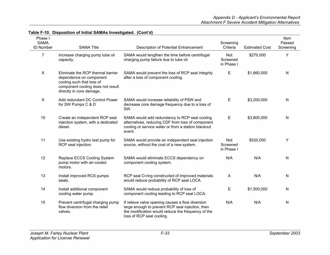
Table F-10. Disposition of Initial SAMAs Investigated. (Cont’d) Phase I SAMA
ID Number SAMA Title Description of Potential Enhancement Screening
Criteria Estimated Cost
Item Passed
Screening
7 Increase charging pump lube oil capacity.
SAMA would lengthen the time before centrifugal charging pump failure due to lube oil
Not Screened in Phase I
$270,000 Y
8 Eliminate the RCP thermal barrier dependence on component cooling such that loss of component cooling does not result directly in core damage.
SAMA would prevent the loss of RCP seal integrity after a loss of component cooling.
E $1,660,000 N
9 Add redundant DC Control Power for SW Pumps C & D
SAMA would increase reliability of PSW and decrease core damage frequency due to a loss of SW.
E $3,200,000 N
10 Create an independent RCP seal injection system, with a dedicated diesel.
SAMA would add redundancy to RCP seal cooling alternatives, reducing CDF from loss of component cooling or service water or from a station blackout event.
E $3,800,000 N
11 Use existing hydro test pump for RCP seal injection.
SAMA would provide an independent seal injection source, without the cost of a new system.
Not Screened in Phase I
$520,000 Y
12 Replace ECCS Cooling System pump motor with air-cooled motors.
SAMA would eliminate ECCS dependency on component cooling system.
N/A N/A N
13 Install improved RCS pumps seals.
RCP seal O-ring constructed of improved materials would reduce probability of RCP seal LOCA
A N/A N
14 Install additional component cooling water pump.
SAMA would reduce probability of loss of component cooling leading to RCP seal LOCA.
E $1,500,000 N
15 Prevent centrifugal charging pump flow diversion from the relief valves.
If relieve valve opening causes a flow diversion large enough to prevent RCP seal injection, then the modification would reduce the frequency of the loss of RCP seal cooling.
N/A N/A N
Appendix D - Applicant’s Environmental Report Attachment F Severe Accident Mitigation Alternatives
Joseph M. Farley Nuclear Plant F-34 September 2003 Application for License Renewal
Table F-10. Disposition of Initial SAMAs Investigated. (Cont’d) Phase I SAMA
ID Number SAMA Title Description of Potential Enhancement Screening
Criteria Estimated Cost
Item Passed
Screening
16 Change procedures to isolate RCP seal letdown flow on loss of component cooling, and guidance on loss of injection during seal LOCA.
SAMA would reduce CDF from loss of seal cooling. B N/A N
17 Implement procedures to stagger HPSI pump use after a loss of service water.
SAMA would allow HPSI to be extended after a loss of service water.
N/A N/A N
18 Use fire protection system pumps as a backup seal injection and high pressure make-up.
SAMA would reduce the frequency of the RCP seal LOCA and the SBO CDF.
C N/A N
19 Procedural guidance for use of cross-tied component cooling or service water pumps.
SAMA would reduce the frequency of the loss of component cooling water and service water.
E $1,750,000 N
20 Procedure enhancements and operator training in support system failure sequences, with emphasis on anticipating problems and coping.
SAMA would potentially improve the success rate of operator actions subsequent to support system failures.
C N/A N
21 Improved ability to cool the residual heat removal heat exchangers
SAMA would reduce the probability of a loss of decay heat removal by implementing procedure and hardware modifications to allow manual alignment of the fire protection system or by installing a component cooling water cross-tie.
B (19)
N/A N
22 Provide reliable power to Control Building fans
SAMA would increase availability of control room ventilation on a loss of power.
A N/A N
23 Provide a redundant train of ventilation.
SAMA would increase the availability of components dependent on room cooling.
C
(22 and 25)
N/A N
Appendix D - Applicant’s Environmental Report Attachment F Severe Accident Mitigation Alternatives
Joseph M. Farley Nuclear Plant F-35 September 2003 Application for License Renewal
Table F-10. Disposition of Initial SAMAs Investigated. (Cont’d) Phase I SAMA
ID Number SAMA Title Description of Potential Enhancement Screening
Criteria Estimated Cost
Item Passed
Screening
24 Procedures for actions on loss of HVAC.
SAMA would provide for improved credit to be taken for loss of HVAC sequences (improved affected electrical equipment reliability upon a loss of Control Building HVAC).
Not Screened in Phase I
$830,000 Y
25 Add a diesel building switchgear room high temperature alarm.
SAMA would improve diagnosis of a loss of switchgear room HVAC.
Option 1: Install high temp alarm
Option 2: Redundant louver and thermostat
A N/A N
26 Create ability to switch fan power supply to direct current (DC) in an SBO event.
SAMA would allow continued operation in an SBO event. This SAMA was created for reactor core isolation cooling system room at Fitzpatrick Nuclear Power Plant.
N/A N/A N
27 Delay containment spray actuation after large LOCA.
SAMA would lengthen time of RWST availability. B N/A N
SAMA would extend the time over which water remains in the RWT, when full CS flow is not needed
B N/A N
29 Install an independent method of suppression pool cooling.
SAMA would decrease the probability of loss of containment heat removal.
N/A N/A N
30 Develop an enhanced drywell spray system.
SAMA would provide a redundant source of water to the containment to control containment pressure, when used in conjunction with containment heat removal.
N/A N/A N
31 Provide dedicated existing drywell spray system.
SAMA would provide a source of water to the containment to control containment pressure, when used in conjunction with containment heat removal. This would use an existing spray loop instead of developing a new spray system.
N/A N/A N
Appendix D - Applicant’s Environmental Report Attachment F Severe Accident Mitigation Alternatives
Joseph M. Farley Nuclear Plant F-36 September 2003 Application for License Renewal
Table F-10. Disposition of Initial SAMAs Investigated. (Cont’d) Phase I SAMA
ID Number SAMA Title Description of Potential Enhancement Screening
Criteria Estimated Cost
Item Passed
Screening
32 Install an unfiltered hardened containment vent.
SAMA would provide an alternate decay heat removal method for non-ATWS events, with the released fission products not being scrubbed.
N/A N/A N
33 Install a filtered containment vent to remove decay heat.
SAMA would provide an alternate decay heat removal method for non-ATWS events, with the released fission products being scrubbed.
Option 1: Gravel Bed Filter
Option 2: Multiple Venturi Scrubber
N/A N/A N
34 Install a containment vent large enough to remove ATWS decay heat.
Assuming that injection is available, this SAMA would provide alternate decay heat removal in an ATWS event.
N/A N/A N
35 Create/enhance hydrogen recombiners with independent power supply.
SAMA would reduce hydrogen detonation at lower cost, Use either a new, independent power supply, a nonsafety-grade portable generator, existing station batteries, or existing AC/DC independent power supplies (security system diesel?).
A N/A N
35A Install hydrogen recombiners. SAMA would provide a means to reduce the chance of hydrogen detonation.
A N/A N
36 Create a passive design hydrogen ignition system.
SAMA would reduce hydrogen denotation system without requiring electric power.
E $1,520,000 N
37 Create a large concrete crucible with heat removal potential under the basemat to contain molten core debris.
SAMA would ensure that molten core debris escaping form the vessel would be contained within the crucible. The water cooling mechanism would cool the molten core, preventing a melt-through of the basemat.
E $90,000,000 N
38 Create a water-cooled rubble bed on the pedestal.
SAMA would contain molten core debris dropping on to the pedestal and would allow the debris to be cooled.
E <$90,000,000 N
Appendix D - Applicant’s Environmental Report Attachment F Severe Accident Mitigation Alternatives
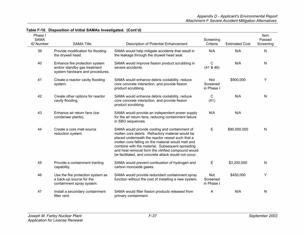
Joseph M. Farley Nuclear Plant F-37 September 2003 Application for License Renewal
Table F-10. Disposition of Initial SAMAs Investigated. (Cont’d) Phase I SAMA
ID Number SAMA Title Description of Potential Enhancement Screening
Criteria Estimated Cost
Item Passed
Screening
39 Provide modification for flooding the drywell head.
SAMA would help mitigate accidents that result in the leakage through the drywell head seal.
N/A N/A N
40 Enhance fire protection system and/or standby gas treatment system hardware and procedures.
SAMA would improve fission product scrubbing in severe accidents.
C (41 & 46)
N/A N
41 Create a reactor cavity flooding system.
SAMA would enhance debris coolability, reduce core concrete interaction, and provide fission product scrubbing.
Not Screened in Phase I
$900,000 Y
42 Create other options for reactor cavity flooding.
SAMA would enhance debris coolability, reduce core concrete interaction, and provide fission product scrubbing.
C (41)
N/A N
43 Enhance air return fans (ice condenser plants).
SAMA would provide an independent power supply for the air return fans, reducing containment failure in SBO sequences.
N/A N/A
44 Create a core melt source reduction system.
SAMA would provide cooling and containment of molten core debris. Refractory material would be placed underneath the reactor vessel such that a molten core falling on the material would melt and combine with the material. Subsequent spreading and heat removal form the vitrified compound would be facilitated, and concrete attack would not occur.
E $90,000,000 N
45 Provide a containment inerting capability.
SAMA would prevent combustion of hydrogen and carbon monoxide gases.
E $3,200,000 N
46 Use the fire protection system as a back-up source for the containment spray system.
SAMA would provide redundant containment spray function without the cost of installing a new system.
Not Screened in Phase I
$450,000 Y
47 Install a secondary containment filter vent.
SAMA would filter fission products released from primary containment.
A N/A N
Appendix D - Applicant’s Environmental Report Attachment F Severe Accident Mitigation Alternatives
Joseph M. Farley Nuclear Plant F-38 September 2003 Application for License Renewal
Table F-10. Disposition of Initial SAMAs Investigated. (Cont’d) Phase I SAMA
ID Number SAMA Title Description of Potential Enhancement Screening
Criteria Estimated Cost
Item Passed
Screening
48 Install a passive containment spray system.
SAMA would provide redundant containment spray method without high cost.
E $2,000,000 N
49 Strengthen primary/secondary containment.
SAMA would reduce the probability of containment overpressurization to failure.
E $3,260,000 N
50 Increase the depth of the concrete basemat or use an alternative concrete material to ensure melt-through does not occur.
SAMA would prevent basemat melt-through. E >$5,000,000
<$90,000,000
N
51 Provide a reactor vessel exterior cooling system.
SAMA would provide the potential to cool a molten core before it causes vessel failure, if the lower head could be submerged in water.
C (41)
N/A N
52 Construct a building to be connected to primary/secondary containment that is maintained at a vacuum.
SAMA would provide a method to depressurize containment and reduce fission product release.
N/A N/A N
53 Not Used N/A N/A N
54 Proceduralize alignment of spare diesel to shutdown board after Loss of Offsite Power and failure of the diesel normally supplying it.
SAMA would reduce the SBO frequency. C (56)
N/A N
55 Not Used N/A N/A N
56 Provide an additional diesel generator.
SAMA would increase the reliability and availability of onsite emergency AC power sources.
E $74,500,000 N
57 Provide additional DC battery capacity
SAMA would ensure longer batter capability during an SBO, reducing the frequency of long-term SBO sequences.
A N/A N
58 Use fuel cells instead of lead-acid batteries.
SAMA would extend DC power availability in an SBO.
N/A N/A N
Appendix D - Applicant’s Environmental Report Attachment F Severe Accident Mitigation Alternatives
Joseph M. Farley Nuclear Plant F-39 September 2003 Application for License Renewal
Table F-10. Disposition of Initial SAMAs Investigated. (Cont’d) Phase I SAMA
ID Number SAMA Title Description of Potential Enhancement Screening
Criteria Estimated Cost
Item Passed
Screening
59 Procedure to cross-tie high pressure core spray diesel.
SAMA would improve core injection availability by providing a more reliable power supply for the high pressure core spray pumps.
N/A N/A N
60 Improve 4.16 kV bus cross-tie ability.
SAMA would improve AC power reliability. A N/A N
61 Incorporate an alternate battery charging capability.
SAMA would improve DC power reliability by either cross-tying the AC buses, or installing a portable diesel-driven batter charger.
A N/A N
62 Increase/improve DC bus load shedding.
SAMA would extend battery life in an SBO event. A N/A N
63 Replace existing batteries with more reliable ones.
SAMA would improve DC power reliability and thus increase available SBO recovery time.
A N/A N
63A Mod for DC Bus A reliability Loss of DC Bus A causes a loss of main condenser, prevents transfer from the main transformer to offsite power, and defeats one half of the low vessel pressure permissive for LPCI/CS injection valves. SAMA would increase the reliability of AC power and injection capability.
A N/A N
64 Create AC power cross-tie capability with other unit.
SAMA would improve AC power reliability. A N/A N
65 Create a cross-tie for diesel fuel oil.
SAMA would increase diesel fuel oil and, thus diesel generator, reliability.
A N/A N
66 Develop procedures to repair or replace failed 4 kV breakers.
SAMA would offer a recovery path from a failure of the breakers that perform transfer of 4.16kV non-emergency buses form unit station service transformers, leading to loss of emergency AC power.
E $7,150,000 N
67 Emphasize steps in recovery of offsite power after an SBO.
SAMA would reduce human error probability during offsite power recovery.
B N/A N
Appendix D - Applicant’s Environmental Report Attachment F Severe Accident Mitigation Alternatives
Joseph M. Farley Nuclear Plant F-40 September 2003 Application for License Renewal
Table F-10. Disposition of Initial SAMAs Investigated. (Cont’d) Phase I SAMA
ID Number SAMA Title Description of Potential Enhancement Screening
Criteria Estimated Cost
Item Passed
Screening
68 Develop a severe weather conditions procedure.
For plants that do not already have one, this SAMA would reduce the CDF for external weather-related events.
B N/A N
69 Develop procedures for replenishing diesel fuel oil.
SAMA would allow for long-term diesel operation. B N/A N
70 Install gas turbine generator. SAMA would improve onsite AC power reliability by providing a redundant and diverse emergency power system.
E $16,100,000 N
71 Not Used N/A N/A N
72 Create a back-up source for diesel cooling. (Not from existing system)
This SAMA would provide a redundant and diverse source of cooling for the diesel generators, which would contribute to enhanced diesel reliability.
A N/A N
73 Use Fire Protection System as a back-up source for diesel cooling.
This SAMA would provide a redundant and diverse source of cooling for the diesel generators, which would contribute to enhanced diesel reliability.
A N/A N
74 Provide a connection to an alternate source of offsite power.
SAMA would reduce the probability of a loss of offsite power event.
A N/A N
75 Bury offsite power lines. SAMA could improve offsite power reliability, particularly during severe weather.
A N/A N
76 Replace anchor bolts on diesel generator oil cooler.
Millstone Nuclear Power Station found a high seismic SBO risk due to failure of the diesel oil cooler anchor bolts. For plants with a similar problem, this would reduce seismic risk. Note that these were Fairbanks Morse DGs.
C (114)
N/A N
Appendix D - Applicant’s Environmental Report Attachment F Severe Accident Mitigation Alternatives
Joseph M. Farley Nuclear Plant F-41 September 2003 Application for License Renewal
Table F-10. Disposition of Initial SAMAs Investigated. (Cont’d) Phase I SAMA
ID Number SAMA Title Description of Potential Enhancement Screening
Criteria Estimated Cost
Item Passed
Screening
77 Change Undervoltage (UV), Auxiliary Feedwater Actuation Signal (AFAS) Block and High Pressurizer Pressure Actuation Signals to 3-out-of-4, instead of 2-out-of-4 logic.
SAMA would reduce risk of 2/4 inverter failure. N/A N/A N
78 Provide DC power to the 120/240 V vital AC system from the Class 1E station service battery system instead of its own battery.
SAMA would increase the reliability of the 120 VAC Bus.
A N/A N
79 Install a redundant spray system to depressurize the primary system during a steam generator tube rupture (SGTR).
SAMA would enhance depressurization during a SGTR.
E $2,270,000 N
80 Improve SGTR coping abilities. SAMA would improve instrumentation to detect SGTR, or additional system to scrub fission product releases.
E $1,670,000 N
81 Add other SGTR coping abilities. SAMA would decrease the consequences of an SGTR.
C N/A N
82 Increase secondary side pressure capacity such that an SGTR would not cause the relief valves to lift.
SAMA would eliminate direct release pathway for SGTR sequences.
E $13,000,000 N
83 Replace steam generators (SG) with a new design.
SAMA would lower the frequency of an SGTR. A N/A N
84 Revise emergency operating procedures to direct that a faulted SG be isolated.
SAMA would reduce the consequences of an SGTR.
B N/A N
85 Direct SG flooding after a SGTR, prior to core damage.
SAMA would provide for improved scrubbing of SGTR releases.
B N/A N
Appendix D - Applicant’s Environmental Report Attachment F Severe Accident Mitigation Alternatives
Joseph M. Farley Nuclear Plant F-42 September 2003 Application for License Renewal
Table F-10. Disposition of Initial SAMAs Investigated. (Cont’d) Phase I SAMA
ID Number SAMA Title Description of Potential Enhancement Screening
Criteria Estimated Cost
Item Passed
Screening
86 Implement a maintenance practice that inspects 100% of the tubes in a SG.
SAMA would reduce the potential for an SGTR. E $3,000,000 N
87 Locate RHR inside of containment.
SAMA would prevent ISLOCA out the RHR pathway.
E $28,000,000 N
88 Not Used. N/A N/A N
89 Install additional instrumentation for ISLOCAs.
Pressure of leak monitoring instruments installed between the first two pressure isolation valves on low-pressure inject lines, RHR suction lines, and HPSI lines would decrease ISLOCA frequency.
Not Screened in Phase I
$425,000 Y
90 Increase frequency for valve leak testing.
SAMA could reduce ISLOCA frequency. C (93)
N/A N
91 Improve operator training on ISLOCA coping.
SAMA would decrease ISLOCA effects. B N/A N
92 Install relief valves in the CC System.
SAMA would relieve pressure buildup from an RCP thermal barrier tube rupture, preventing an ISLOCA.
B N/A N
93 Provide leak testing of valves in ISLOCA paths.
At Kewaunee Nuclear Power Plant, four MOVs isolating RHR from the RCS were not leak tested. This SAMA would help reduce ISLOCA frequency.
B N/A N
94 Revise EOPs to improve ISLOCA identification.
Salem Nuclear Power Plant had a scenario where an RHR ISLOCA could direct initial leakage back to the pressurizer relief tank, giving indication that the LOCA was inside Containment. Procedure enhancements would ensure LOCA outside Containment could be identified as such.
B N/A N
95 Ensure all ISLOCA releases are scrubbed.
This SAMA would scrub all ISLOCA releases. One example is to plug drains in the break area so that the break point would cover with water.
A N/A N
Appendix D - Applicant’s Environmental Report Attachment F Severe Accident Mitigation Alternatives
Joseph M. Farley Nuclear Plant F-43 September 2003 Application for License Renewal
Table F-10. Disposition of Initial SAMAs Investigated. (Cont’d) Phase I SAMA
ID Number SAMA Title Description of Potential Enhancement Screening
Criteria Estimated Cost
Item Passed
Screening
96 Add redundant and diverse limit switches to each containment isolation valve.
Enhanced isolation valve position indication could reduce the frequency of containment isolation failure and ISLOCAs.
Not Screened in Phase I
$960,000 Y
97 Modify swing direction of doors separating turbine building basement from areas containing safeguards equipment.
SAMA would prevent flood propagation, for a plant where internal flooding from turbine building to safeguards areas is a concern.
A N/A N
98 Improve inspection of rubber expansion joints on main condenser.
SAMA would reduce the frequency of internal flooding, for a plant where internal flooding due to a failure of circulating water expansion joints is a concern.
A N/A N
99 Implement internal flood prevention and mitigation enhancements.
This SAMA would reduce the consequences of internal flooding.
C (116-118)
N/A N
100 Implement internal flooding improvements such as those implemented at Fort Calhoun.
This SAMA would reduce flooding risk by preventing or mitigating :
(1) a rupture in the RCP seal cooler of the component cooling system
(2) an ISLOCA in a shutdown cooling line,
(3) an AFW flood involving the need to remove a watertight door.
C (99)
N/A N
101 Install a digital feedwater upgrade. This SAMA would reduce the chance of a loss of main feedwater following a plant trip.
Not Screened in Phase I
$900,000 Y
102 Perform surveillances on manual valves used for back-up AFW pump suction.
This SAMA would improve success probability for providing alternative water supply to the AFW pumps.
Not Screened in Phase I
$1,000,000 Y
Appendix D - Applicant’s Environmental Report Attachment F Severe Accident Mitigation Alternatives
Joseph M. Farley Nuclear Plant F-44 September 2003 Application for License Renewal
Table F-10. Disposition of Initial SAMAs Investigated. (Cont’d) Phase I SAMA
ID Number SAMA Title Description of Potential Enhancement Screening
This SAMA would reduce the dual turbine-driven AFW pump maintenance unavailability.
A N/A N
104 Install accumulators for turbine-driven AFW pump flow control valves (CVs).
This SAMA would provide control air accumulators for the turbine-driven AFW flow CVs, the motor-driven AFW pressure CVs and SG PORVs. This would eliminate the need for local manual action to align nitrogen bottles for control air during a LOOP.
A N/A N
105 Proceduralize intermittent operation of HPCI.
SAMA would allow for extended duration of HPCI availability.
N/A N/A N
106 Increase the reliability of safety relief valves. (Adding signals to add electrical signal to open automatically).
SAMA reduces the probability of a certain type of medium break LOCA. Hatch evaluates medium LOCA initiated by an MSIV closure transient with a failure of SRVs to open. Reducing the likelihood of the failure for SRVs to open, subsequently reduces the occurrence of this medium LOCA.
N/A N/A N
107 Install motor-driven feedwater pump.
This would increase the availability of injection subsequent to MSIV closure.
E $2,200,000 N
108 Procedure to instruct operators to trip unneeded RHR/CS pumps on loss of room ventilation.
SAMA increases availability of required RHR/CS pumps. Reduction in room heat load allows continued operation of required RHR/CS pumps, when room cooling is lost.
C (24)
N/A N
109 Increase available NSPH for injection pumps.
SAMA increases the probability that these pumps will be available to inject coolant into the vessel by Increasing the available NPSH for the injection pumps.
A N/A N
110 Increase the SRV reseat reliability.
SAMA addresses the risk associated with dilution of boron caused by the failure of the SRVs to reseat after SLC injection.
N/A N/A N
Appendix D - Applicant’s Environmental Report Attachment F Severe Accident Mitigation Alternatives
Joseph M. Farley Nuclear Plant F-45 September 2003 Application for License Renewal
Table F-10. Disposition of Initial SAMAs Investigated. (Cont’d) Phase I SAMA
ID Number SAMA Title Description of Potential Enhancement Screening
Criteria Estimated Cost
Item Passed
Screening
111 Reduce DC dependency between high pressure injection system and ADS.
SAMA would ensure containment depressurization and high pressure injection upon a DC failure.
N/A N/A N
112 Modify RWCU for use as a decay heat removal system and proceduralize use.
SAMA would provide an additional source of decay heat removal.
N/A N/A N
113 Use of CRD for alternate boron injection.
SAMA provides an additional system to address ATWS with SLC failure or unavailability.
N/A N/A N
114 Increase seismic ruggedness of plant components.
SAMA would increase the availability of necessary plant equipment during and after seismic events.
A N/A N
115 Allow cross connection of uninterruptable compressed air supply to opposite unit.
SAMA would increase the ability to depressurize containment using the hardened vent.
N/A N/A N
116 Install flooding alarm in Cable Spreading Room
SAMA would allow early detection of flooding due to Fire Protection System Failures.
A N/A N
117 Leak-tight enclosure for Fire Protection piping in Unit 1 Cable Spreading Room
SAMA would eliminate flooding scenario. Not Screened in Phase I
$122,000 Y
118 Improve reliability of Fire Protection clapper valves in the Cable Spreading Room
SAMA would reduce spurious trips and therefore lower flooding exposure.
SAMA would provide notification of local Service Water faults and allow for recovery from those failures.
Not Screened in Phase I
$930,000 Y
120 Seal electrical cabinets in Cable Spreading Room to prevent water intrusion during room flooding
SAMA would lengthen time for potential discovery and recovery from flooding event.
Not Screened in Phase I
$475,000 Y
Appendix D - Applicant’s Environmental Report Attachment F Severe Accident Mitigation Alternatives
Joseph M. Farley Nuclear Plant F-46 September 2003 Application for License Renewal
Table F-10. Disposition of Initial SAMAs Investigated. (Cont’d) Phase I SAMA
ID Number SAMA Title Description of Potential Enhancement Screening
Criteria Estimated Cost
Item Passed
Screening
121 Modify Unit 2 SW Pumps to eliminate dependence on lube & cooling booster pumps
SAMA would improve the reliability of the SW Pumps
E $1,760,000 N
122 Replace RHR HX heads with stronger material
SAMA would reduce the probability of failure during ISLOCA
E $1,400,000 N
123 Install pressure sensor between RHR isolation MOVs to allow detection of unseated outboard isolation valve
SAMA would reduce ISLOCA potential Not Screened in Phase I
$330,000 Y
124 Redesign CCW miscellaneous header to allow either train to supply RCP thermal barrier without need for local manual re-alignment
SAMA would add reliability by removing the need for operator action.
E $1,746,000 N
125 Install auto-start of standby CCW train on loss of on-service train pressure
SAMA would add reliability by removing the need for operator action.
Not Screened in Phase I
$1,000,000 Y
*Screening Criteria
A – Already addressed by existing FNP design. B – Already addressed by existing FNP procedures. C – Addressed by other SAMAs (Other SAMA numbers in parentheses) D – Already addressed by FNP training program E – Estimated cost exceeds twice the maximum attainable benefit from internal events mitigation N/A – Not applicable to FNP.
Appendix D - Applicant’s Environmental Report Attachment F Severe Accident Mitigation Alternatives
Joseph M. Farley Nuclear Plant F-47 September 2003 Application for License Renewal
Table F-11. Summary of Phase II SAMA Analyses.
SAMA ID number
Averted offsite exposure
Averted offsite cost
Averted onsite
exposure
Averted onsite
cleanup cost
Averted replacement
power Total
benefits Cost of
implementation Net value of modifications
SAMA 7 $396 $6 $1,150 $35,757 $22,312 $59,621 $270,000/unit ($210,379/unit) SAMA 11 $2,179 $39 $4,403 $136,952 $85,455 $229,028 $520,000/unit ($290,972/unit) SAMA 24 $1,849 $456 $1,198 $37,264 $23,252 $64,019 $830,000/unit ($765,981/unit) SAMA 89 $14,954 $15,997 $127 $3,954 $2,467 $37,500 $425,000/unit ($387,500/unit) SAMA 96 $14,954 $15,997 $127 $3,954 $2,467 $37,500 $960,000/unit ($922,500/unit) SAMA 101 $1,624 $24 $1,759 $54,697 $34,130 $92,233 $900,000/unit ($807,767/unit) SAMA 117 $234 $5 $160 $4,972 $3,103 $8,474 $122,000/unit ($113,526/unit) SAMA 118 $215 $4 $147 $4,558 $2,844 $7,768 $122,000/unit ($114,232/unit) SAMA 119 $1,849 $456 $1,198 $37,264 $23,252 $64,019 $930,000/unit ($865,981/unit) SAMA 120 $471 $10 $322 $10,004 $6,242 $17,049 $475,000/unit ($457,951/unit) SAMA 123 $14,954 $15,997 $127 $3,954 $2,467 $37,500 $330,000/unit ($292,500/unit)
Appendix D - Applicant’s Environmental Report Attachment F Severe Accident Mitigation Alternatives
Joseph M. Farley Nuclear Plant F-48 September 2003 Application for License Renewal
6.0 CONCLUSIONS
None of the 11 SAMAs analyzed in detail in Phase II had estimated benefits that were close to, or exceeded, the cost of implementation; even when considering the contributions of external event contributors to the CDF. These 11 SAMAs had large negative net benefits relative to the cost of implementing the SAMA, indicating that such SAMAs would not be cost-beneficial.
Appendix D - Applicant’s Environmental Report Attachment F Severe Accident Mitigation Alternatives
Joseph M. Farley Nuclear Plant F-49 September 2003 Application for License Renewal
7.0 REFERENCES
1. Generic Letter No. 88-20, “Individual Plant Examination for Severe Accident Vulnerabilities – 10 CFR §50.54(f),” NRC Letter to All Licensees Holding Operating Licenses and Construction Permits for Nuclear Power Reactor Facilities, November 23, 1988.
2. Generic Letter No. 88-20, Supplement 1, “Initiation of the Individual Plant Examination for Severe Accident Vulnerabilities – 10 CFR §50.54(f),” August 29, 1989 and Supplement 2, “Accident Management Strategies for Consideration in the Individual Plant Examination Process,” April 4, 1990.
3. NUREG/CR-2300, “PRA Procedures Guide – A Guide to the Performance of Probabilistic Risk Assessments for Nuclear Power Plants,” January 1983.
5. EPRI, “MAAP 3.0B Complete Code Manual,” EPRI NP-777-1-CCML, 1990 and “MAAP 4 User’s Manual,” EPRI RP 3131-02, May 1994.
6. SNC Technical Services Calculation PSA-F-98-003, “PRA Revision 1 including conversion to CAFTA and EOOS At-power model,” March 1998.
7. SNC Technical Services Calculation PSA-F-98-004, “EOOS Status Panel and Test.dbf revision (Rev. 2),” May 1998.
8. Technical Services Calculation PSA-F-99-007, “Joseph M. Farley Nuclear Plants Units 1 and 2 Data Update for Probabilistic Risk Analysis,” June 1999.
9. NUREG/CR-5750, “Rates of Initiating Events at U.S. Nuclear Power Plants: 1987-1995,” February 1999.
10. SNC Technical Services Calculation PSA-F-99-010, “Joseph M. Farley Nuclear Plant Units 1 and 2 PRA Model and EOOS Revision 3,” August 1999.
13. Technical Services Calculation PSA-F-01-017, “Farley Units 1 and 2 PRA and EOOS Revision 5,” October 2001.
14. Chanin, D. and Young, M., Code Manual for MACCS2: Volume 1, User’s-Guide, SAND 97-0594, 1997.
15. NUREG-1150, “Severe Accident Risks: An Assessment for Five U.S. Nuclear Power Plants,” U.S. Nuclear Regulatory Commission, Washington, D.C., June 1989.
16. Evacuation Time Estimates for the Farley Nuclear Plant, HMM Associates, July 1993.
17. U.S. Department of Agriculture, “1997 Census of Agriculture,” National Agricultural Statistics Service, 1998.
Appendix D - Applicant’s Environmental Report Attachment F Severe Accident Mitigation Alternatives
Joseph M. Farley Nuclear Plant F-50 September 2003 Application for License Renewal
18. U.S. Department of Agriculture, “Usual Planting and Harvesting Dates for Crops in South Carolina,” National Agricultural Statistics Service, http://usda.mannlib.cornell.edu/reports/nassr/field/planting/uph97.pdf, December 1997.
19. Alabama Cooperative Extension, “Planting Guide For Home Gardening In Alabama,” http://www.aces.edu/department/extcomm/publications/anr/ANR-63/anr-63.htm, April 1998.
20. Southern Nuclear Operating Company, "Severe Accident Mitigation Alternatives at the Edwin I. Hatch Nuclear Plant." Attachment F of Appendix D (Applicant's Environmental Report - Operating License Renewal Stage) of Edwin I. Hatch Nuclear Plant Application for License Renewal. February 2000.
21. NUREG-1437, “Generic Environmental Impact Statement for License Renewal of Nuclear Plants, Calvert Cliffs Nuclear Power Plant,” Supplement 1, U.S. Nuclear Regulatory Commission, Washington, D.C., February 1999.
22. John E. Till and H. Robert Meyer, Radiological Assessment, A Textbook on Environmental Dose Analysis, NUREG/CR-3332, ORNL-5968, p. 2-23. September 1983, prepared for USNRC, Washington, D.C.
23. “Local Climatological Data, Annual Summaries for 1999, Part II Southern Region,” Montgomery, Alabama (MGM), National Climatic Data Center, Asheville, N.C.
24. “Mixing Heights, Wind Speeds, and Potential for Urban Pollution Throughout the Contiguous United States,” George C. Holzworth, EPA, Office of Air Programs, Research Triangle Park, North Carolina, January 1972.