58
Attachment No. D For inspection purposes only. Consent of copyright owner required for any other use. EPA Export 25-07-2013:19:54:33
Attachment No. D
For
insp
ectio
n pur
pose
s only
.
Conse
nt of
copy
right
owne
r req
uired
for a
ny ot
her u
se.
EPA Export 25-07-2013:19:54:33
1 Description of the Installation
1 .I Identification of Dangerous Substances
The predominant Seveso I I substances stored and processed in Dynea Ireland are Methanol, Formaldehyde and Dowtherm.
The full list of Seveso II substances at Dynea Ireland is given in Appendix 12 of this Safety Report.
Appendix 13 contains descriptions of the physical and chemical behaviour of each substance.
1.2 Classification of Dangerous Substances The classification of a chemical as dangerous substance is based on an evaluation of the hazards associated with that chemical. The hazards are due to the intrinsic properties of the chemical. These intrinsic properties are based on knowledge of the toxicological, physiochemical and eco-toxicological properties of the chemical. The substance is classified for the appropriate endpoint based on criteria outlined in Schedule 5 of the CPL Substances Regs S.I. 116 of 2003. These are listed below.
1. Verv Toxic @ 2. Toxic
3. Harmful 4. Corrosive 5. Irritant 6. Explosive 7. Oxidising 8. Extremely Flammable 9. Highly Flammable I O . Dangerous to the Environment
T+ T X" C Xi E 0 F+ F
Risk phrases (which describe the hazard in greater detail) and safety phrases (which give appropriate handling advice to control the hazard) are used in the classification. An example of a phrase used is given below.
R50: 'Very toxic to aquatic organisms
Substances that have been classified at European Union level to date as dangerous to human health or the environment are listed on Annex 1 of Directive 67/548/EEC. This is updated regularly by what is called an ATP (Adaptation to Technical Progress) when new information is made available about 0 certain substances.
1.3 Description of Dangerous Substances
1.3.1 Methanol storage and process conditions
Methanol is a member of the functional group of chemicals known as alcohols with the characteristic - OH grouping attached. These chemicals undergo oxidisation reactions readily to form the corresponding aldehyde. Further oxidisation of the aldehyde results in the formation of the acid. Dynea Ireland Ltd utilise this reaction to produce methanal from methanol. Methanol is a colourless clear liquid with a boiling point of 64OC, relative density of 0.79(Kg/L) and vapour pressure of 97mmHG at 20°C. It is highly soluble with polar and non-polar solvents alike. It is volatile and highly flammable.
Methanol is stored as a liquid at ambient temperature and pressure in a tank with diameter 20m, height 16m. Hence the maximum capacity is 5,027m3. The specific gravity of methanol is 0.7971, and hence the maximum quantity stored is 3,929 tonnes. However, the practical maximum quantity is 3,600m3, due to the overflow pipe. @
Page 1 of 58
For
insp
ectio
n pur
pose
s only
.
Conse
nt of
copy
right
owne
r req
uired
for a
ny ot
her u
se.
EPA Export 25-07-2013:19:54:33
.-
The Methanol bund capacity is 5,500m3.The tank diameter is 20m and the capacity 3,800 tonnes. The tank itself has a floating roof. Above the floating roof there is a blanket of Nitrogen. Around 2 sides of the tank there are 5 foam monitors. Methanol is pumped from the tank to the formox process, reactors and to road tankers in the methanol loading area. In the event of a tank rupture the contents of the tank would be contained within the bund. A methanol vapour cloud would develop in the area.
@
Under process conditions methanol (2700kgs) is pumped to the formox process vaporizer where it is mixed with incoming air (20000Nm3) at a temperature of 130°C. The reaction that takes place between methanol/air mixture and the catalyst within the converter is exothermic, and the excess heat is removed using Dowtherm oil as the heat transfer medium. The excess heat is used to produce high/low pressure steam. The process parameters for the aidmethanol mixture are such that they are within the safe explosive limits. This low oxygen in air content is achieved through using a mixture of air and recycled air from absorber stack. Approximately 1/3 of the total air flow through the absorber is used as recycle gas in the converter. The other 2/3 is thermally oxidised in the catalytic oxidiser.
Methanol is also used as an ingredient in some resins at low concentration (2000kgs). The methanol is added into the reactor after formalin addition. This mixture is highly stable. The temperature within the reactor is at 50°C at this stage. If heating is lost under these conditions, the worst case scenario is formation of paraformaldehyde. Paraformaldehyde is classed as a flammable solid material.
Methanol is also sold to customers. A road tanker loading facility is located beside the methanol storage tank.
The capacity of a road tanker is 27m3, but the normal cargo is 24 m3 (19.2 tonnes). a 1.3.1.1 Formaldehyde Properties Formalin is a colourless liquid with a strong pungent smell. It is highly soluble in water. At temperatures below 45°C formalin will begin to polymerise to form paraformaldehyde. The product solution produced at the plant contains small amounts of formic acid and unreacted methanol (less than 1%).
Formaldehyde is a toxic, flammable gas.
Formaldeyde is a member of the functional group of chemicals known as aldehydes. Aldehydes contain an external carbonyl group attached to alkyl substituent and a Hydrogen (-CHO).
Formaldehyde is formed through the direct oxidation of methanol. The formaldehyde gas is flammable and will form explosive mixtures with air and oxygen. This formaldehyde gas is absorbed in water to form a 55% solution of formaldehyde known as formalin.
Under EC legislation formaldehyde is classified as a Category Ill carcinogen, which means that its has
Q not been shown to be carcinogenic to humans, although-it has been shown to cause cancer in animals.
Formalin is stored in the 2 designated lagged tanks. The maximum capacity of these tanks 600m3. These tanks are kept at approximately 45°C to prevent formation of paraformaldehyde. If either of the tanks ruptured liquid formaldehyde would splash onto the road in front of the tanks whilst most of the contents of the tank would be contained within the bund. A toxic vapour cloud would develop.
1.3.1.2 Dowtherm Properties Dowtherm is used by Dynea as a heat transfer fluid within its process operations. Its normal application range is between 15 and 400°C and its pressure range is between atmospheric and 1 Obar.
Dowtherm is stable and does not decompose readily at high temperatures and can be used in either liquid/vapour phase systems.
Dowtherm is purchased from the Dow Chemical Company in 200L drums. This liquid is pumped into a storage tank with a capacity of 12m3. The storage tank is kept at ambient temperature. If the tank was to iupture, its contents would be contained within the formox bund. In the event of a fire Dowtherm would evolve trace amounts of Benzene and phenol. There would also be thick black smoke. 0
Page 2 of 58
For
insp
ectio
n pur
pose
s only
.
Conse
nt of
copy
right
owne
r req
uired
for a
ny ot
her u
se.
EPA Export 25-07-2013:19:54:33

Dowtherm is used specifically to remove excess heat of reaction from the converter and to produce high pressure steam in the Dowtherm condenser. Under process conditions the Dowtherm level will be above the reaction tubes in the converter. At the top of the tubes where conversion of methanol to formaldehyde is at its lowest (inert catalyst) the temperature is at 250°C . Approximately midway down the tubes the temperature will rise to 350°C due to complete chemical oxidation of the methanol (exothermic). This excess heat is taken up by the Dowtherm and it begins to vaporise. The average temperature throughout the Dowtherm oil is 257'C. These vapours return to the Dowtherm separator and from there to the Dowtherm condenser where high pressure steam is produced. The cooled Dowtherm from the condenser is returned to the separator and back into the converter at approximately 220°C. Pressure is put on the converter 0.2 bar when the catalyst is at the end of its life. This increases the rate of chemical reaction in the converter and prolongs life of the catalyst.
During shutdown the Dowtherm is kept heated to prevent it from freezing.
Dowtherm has the risk phrase R50 (Very toxic to aquatic organisms) associated with it and must therefore be prevented from entering any water source.
If the Dowtherm level drops in the converter, the excess heat will not be removed, and the tubes within the catalytic converter may crack. Dowtherm will flow into the tubes and may cause a fire. The activity of the catalyst will also be destroyed. If the level of Dowtherm in the converter is too high heat transfer problems may result, but this situation is not unsafe.
e 1 Page 3 of 58 ! ;
For
insp
ectio
n pur
pose
s only
.
Conse
nt of
copy
right
owne
r req
uired
for a
ny ot
her u
se.
EPA Export 25-07-2013:19:54:33
1.3.1.3 Auxiliary Chemicals In addition to the above bulk chemicals the following c..emicals are also used within Dynea in the manufacturing process in smaller quantities. The substances listed below are not Seveso I1 substances as outlined in Schedule 5 of S.1 476 of 2000. %)
a. Ammonia Water Ammonia water is normally added to the reactor from an IBC through an open melamine chute when there is only pH adjusted formalin and urea in the reactor and the temperature in the reactor is 55°C. The ammonia gets integrated into the polymer as the condensation progresses and imparts improved water dilutability to the final resin.
b. Ammonium Sulphate Ammonium Sulphate is used as an acid in the resin production process. The material reacts with formaldehyde to form sulphuric acid according to the reaction:
The ammonium sulphate can be added at various stages of the process but the typical addition stage is at the end of the post urea 1 exotherm when the temperatures are in the order of 75°C to 85°C. The only adverse reaction here is'that Hexamethylenetetramine (or Hexamine) is a very strong retarder of resin curing and is sometimes added to resins to slow the gel time. As a result, too much pH adjustment will lead to the creation of buffering salts which affect resin performance. For this reason it is preferable to add as little Ammonium Sulphate as possible. This reaction only has an impact on product quality and has no safety implications.
Ammonium Sulphate is stored in a stainless steel tank on the reactor floor. This product is stable under normal conditions. This product will decompose at temperatures above 235 'C to Ammonia.
c. Caprolactam Caprolactam is stored on site but is no longer used within the manufacturing process.
Caprolactam is stored at ambient temperature and pressure in the warehouse. It was previously added to a Melamine-Formaldehyde paper impregnation resin to add water tolerance to the product (i.e. more water could be added to the resin) but this is no longer the case. The material currently present will remain in storage until such time as a buyer can be found for it. It is stored in 25kg plastic bags on a pallet so no risk accrues from its storage conditions.
caprolactam is stable under normal conditions. It has a flash point of 139 'C and material fines accidentally released in air can result in explosive mixture. Materials to be avoided are all oxidising agents. In the event of a fire the products of combustion include Carbon Dioxide and Nitrous Oxides compounds. Caprolactam is highly water-soluble and it is readily degradable in soil and water and is non-toxic to water organisms. It does not bioaccumalate. In the event of a spillage safety glasses and
@ gloves are required.
d. Diethylene Glycol Diethylene Glycol is added as a plasticizer to Melamine-Formaldehdye paper impregnation resins. It is the first ingredient added in the batch so the reactor is empty and cool at this point. Formalin at approx. 50°C is then added.
Diethyene Glycol is stored in the chemical bund. It is hygroscopic and is unstable on exposure to moisture.
e. Formic Acid Formic acid is generated during the manufacture of formaldehyde from methanol in the Formox process so it is present in all the formaldehyde used on site in small quantities (approx. 200mg/l).
For some of the resin types made initially, the presence of high formic acid (>300mg/l) in the formaldehyde could affect the quality of the resin as formic acid lengthens the curing time due to the formation of sodium formate (which causes a buffering effect thereby retarding the acidification of the system during the acid gel test).
This buffering effect is now seen as beneficial for some of the current resin types and so small quantities of formic are added to bring the levels in the finished resin up to approx. 600mg/l. 0
I
Page 4 of 58 !
For
insp
ectio
n pur
pose
s only
.
Conse
nt of
copy
right
owne
r req
uired
for a
ny ot
her u
se.
EPA Export 25-07-2013:19:54:33
These are the only known reactions of formic acid in the resin system.
Formic Acid is stored in the chemical bund. It has a flash point of 65'C. In the event of a fire the products of combustion include carbon dioxide and water. It reacts exothermically with alkalis, amines and products containing amines.
j. Cooling Water Chemicals These materials are pumped at a fixed rate by a dosing pump into the cooling water and boiler systems. The only possible safety effect here would be if the dosing levels were not high enough and corrosion of the protected systems was to occur. To prevent this occurrence, the laboratory tests the
f. Melamine Melamine is added to certain resin types where moisture resistance of the finished board is desirable. It is added either to a reaction containing urea and formaldehyde to create resin for moisture resistant board (mUF and MUF) or to formaldehyde to create resins for paper impregnation (worktop surfaces) - MF. It is added to the reactor directly after the formaldehyde in the case of MF resins at approx. 28°C and reacts with the formaldehyde to form the polymer as the temperature is increased to 103°C. For the mUF resins (smaller levels of melamine - 2%w/w) it is added after the post urea addition exotherm (at approx. 70°C) and for the MUF (>-IO% w/w) there is a further addition post condensation stage at approx. 85°C.
Melamine is stored in a well-ventilated main store. It is stable under normal conditions. In the event of a fire melamine will decompose at high temperatures to form Nitrous Oxides and Ammonia. There are no other chemicals stored in this area which Melamine is incompatible with. The USEPA have classified the final product in its current form as non hazardous.
g. Sodium Formate Sodium formate causes a buffering effect thereby retarding the acidification of the system during the acid gel test. Where the addition of formic acid (see above) has not resulted in a sufficiently slow curing time sodium formate is mixed with water and a quantity added to the resin at approx. 30°C in the reactor. No reactions which have an adverse safety effect have been documented. Sodium formate is stored in the main store away from any strong acids. It is stable under normal conditions this substance decomposes on heating into sodium oxalate and carbon monoxide which are toxic and on contact with acids produces vapours of formic acid. Sodium formate is non toxic and is easily biodegradable.
Sodium Hydroxide is added to the resin to adjust the pH and bring the reaction to a close (in the case of acid catalysed reactions or begin the reaction (in the case of base catalysed reactions). The resin will be at a maximum of approx. 90°C when this happens. Most reactions are ultimately both acid and base catalysed so the addition of too much sodium hydroxide to bring a reaction to a halt could result in a gelation. This will have only production downtime effects - the reaction cannot result in a dangerous exotherm of other serious safety effect. The other negative aspect of a gelation would be the generation of significant quantities of solids waste for either disposal or rework.
Sodium Hydroxide is stored in own designated carbon steel tank (T405) at a concentration of 28%w/w at ambient temperature. In the event of a fire, sodium hydroxide forms flammable and explosive hydrogen gas by corrosion of metals. There are no chemicals in this area that Sodium Hydroxide is incompatible with. In the event of a spillage Sodium Hydroxide will be contained in the bunded area. Since Sodium Hydroxide is toxic to aquatic organism it must be neutralised before it can be discharged.
h. Sodium Hydroxide
@
i. Sulphuric Acid Sulphuric acid is stored in the chemical bund. In the event of fire oxides of sulphur are evolved. Most metals will be corroded by sulphuric acid with the evolution of flammable Hydrogen gas. Sulphuric acid is stored in IBCs. All spillages from the IBC will be contained within the bund. Sulphuric acid is very toxic to aquatic organism. Neutralisation with lime prior to disposal is required. The protective equipment required when handling sulphuric acid includes self-contained breathing apparatus and acid suit with facemask.
Page 5 of 58 l~ 11
For
insp
ectio
n pur
pose
s only
.
Conse
nt of
copy
right
owne
r req
uired
for a
ny ot
her u
se.
EPA Export 25-07-2013:19:54:33
The majority of these chemicals have only a slight percentage of active ingredient. These chemicals are stored in the chemical bund. In the event of a fire, fumes of carbon monoxide, carbon dioxide, nitrous oxides, Chlorine gas, and bromine gas will be evolved. In the event of a small spillage it can be released to waste water treatment. Larger spills need to be put into containers and the remainder absorbed using spill kits. Personal protective equipment required includes safety glasses, gloves and breath i ng apparatus.
1.3.2 Site Waste Streams
Waste resin is fully cured by the addition of acid before it is disposed of. The cured resin is non- hazardous and does not pose a threat to the environment. Disposal of this material to landfill is approved under the terms of the plant's Integrated Pollution Control Licence as long as the material is sent for disposal via an approved contractor.
Waste Solvents (laboratory and plant) - these are collected in appropriate containers (as determined by the HSE Manager or DGSA) and sent for disposal via an approved contractor - stored in IBC bund (AVR-Safeway Ltd.).
1.3.2.1 By-products - Normal Operation
Dimethyl ether is formed as a by product of formaldehyde manufacture (see Section 1.4.6.2).
1.3.2.2 By-products - Unplanned Operation
Gelled resin - non hazardous material formed by resin being over cured in the reactor. It can be safely disposed of in landfill.
Paraformaldehyde - classed as a flammable solid material. Essentially a polymer of formaldehyde caused by the temperature of formalin solution falling below that which is necessary for stability. Classified as a hazardous material for the purposes of waste disposal and needs to be incinerated.
1.4 Establishment Information
1.4.7 Introduction
The Dynea Ireland site built to manufacture urea formaldehyde, melamine urea formaldehyde and melamine formaldehyde resins, is leased from Irish Fertilizer Industries (in liquidation), some of whose facilities are shared, including the:
0 Jetty. 0 Fire water storage 0 Security
@
The Dynea site was selected for a number of reasons:
0 Proximity to supply of major raw material, urea 0 Availability of jetty for importation of methanol 0 Road infrastructure 0 Sea transport from Cork 0 Local skilled labour
The factory manufactures formaldehyde resins by converting methanol to formaldehyde, and then mixing the formaldehyde in aqueous solution with urea or melamine. The process is well-proven technology and has been operated for 40 years. The formulations of resins are proprietary @ information.
Page 6 of 58
For
insp
ectio
n pur
pose
s only
.
Conse
nt of
copy
right
owne
r req
uired
for a
ny ot
her u
se.
EPA Export 25-07-2013:19:54:33
I
Dynea holds patents on the Formox process and 15 other plants use the resin technology supplied by Dynea.
This Section gives an overview of the key operating and design parameters for the process and storage systems on site.
1.4.2 Plant Design Parameters
Process and storage vessels within Dynea are designed to a wide variety of standards and operating parameters which are described through the following sections.
Appendix 20 details the process and operating parameters for equipment on the Dynea site.
1.4.3 Safety Critical Systems
Identification of safety critical devices, scheduling of maintenance, type of maintenance required on the safety critical devices is decided on by, Production Manager, HSE Manager, Plant Chemist and Maintenance Supervisor. The process by which they identify this equipment is by evaluating the risks associated with the equipment if the device fails to operate correctly, i.e. loss of life, serious injury, damage to property and plant, effects on the environment. The risks are then ranked and a programme of preventative maintenance is put in place specifically for these critical devices. Safety critical devices are inputted by the Production Manager onto the database. To distinguish this safety equipment from other equipment that require maintenance an asterix is placed beside the device to differentiate them from other equipment when entering it on the database. When the due date for maintenance of the safety critical devices approaches a message is highlighted in red on the database and maintenance of this equipment will take precedence over any other equipment maintenance.
\
A validation programme is in place whereby the safety critical devices and control systems are tested to ensure that they work correctly in the accident situation. The plant is divided into three areas Formox, Resin and Utilities, all the safety critical devices in these areas are logged and a testing programme is put in place. Simulations are carried out which will show whether or the device is operating as it should under certain situations. The results of these tests are recorded and any improvements required will be communicated to the HSE Manager and Production Manager for corrections. Any alterations to plant will be communicated via e-mail and also placed on notice boards.
Appendix 21 outlines a list of all identified Safety Critical Devices.
1.4.4 Automatic Control System e
Process and storage operations within Dynea are a combination of both automated and manual operations. The following sections give an overview of how some of the site process operations are conducted.
1.4.4.1 Formox process The formox is a standard process and is operated in many Dynea plants worldwide. The process is the direct oxidation of methanol over an iron/ molybdenum catalyst. The formox has key safety critical events built into its safety system. There are interlocks on the system which when a process condition is outside safety critical parameters the plant will shutdown. These systems fail in the safe mode and prevent human input from initiating unsafe plant operating conditions. A list of the safety critical events is given in Figure 1 below.
The responsibility for running the formox process lies with the Shift Supervisor. They have been trained at Dynea plants across Europe on the safe operation of the formox. Plant start-up and shutdown have been seen as the critical steps in the formox process. The Production Manager with the Quality Manager carries out these steps. The automated control system is based on the Uniview 0
Page 7 of 58
For
insp
ectio
n pur
pose
s only
.
Conse
nt of
copy
right
owne
r req
uired
for a
ny ot
her u
se.
EPA Export 25-07-2013:19:54:33
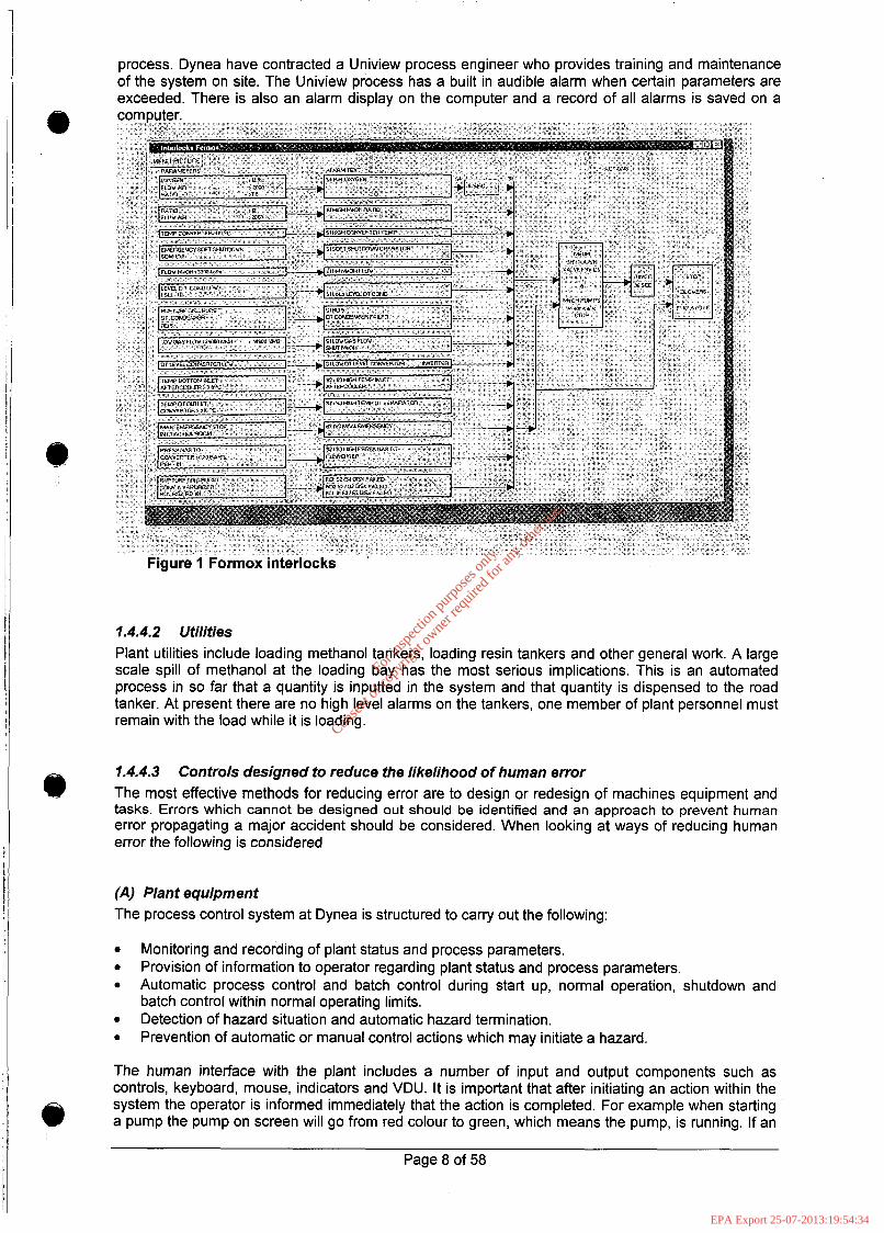
process. Dynea have contracted a Uniview process engineer who provides training and maintenance of the system on site. The Uniview process has a built in audible alarm when certain parameters are exceeded. There is also an alarm display on the computer and a record of all alarms is saved on a
1.4.4.2 Utilities Plant utilities include loading methanol tankers, loading resin tankers and other general work. A large scale spill of methanol at the loading bay has the most serious implications. This is an automated process in so far that a quantity is inputted in the system and that quantity is dispensed to the road tanker. At present there are no high level alarms on the tankers, one member of plant personnel must remain with the load while it is loading.
1.4.4.3 The most effective methods for reducing error are to design or redesign of machines equipment and tasks. Errors which cannot be designed out should be identified and an approach to prevent human error propagating a major accident should be considered. When looking at ways of reducing human error the following is considered
Controls designed to reduce the likelihood of human error
(A) Plant equipment The process control system at Dynea is structured to carry out the following:
0
0
0
0
0
Monitoring and recording of plant status and process parameters. Provision of information to operator regarding plant status and process parameters. Automatic process control and batch control during start up, normal operation, shutdown and batch control within normal operating limits. Detection of hazard situation and automatic hazard termination. Prevention of automatic or manual control actions which may initiate a hazard.
The human interface with the plant includes a number of input and output components such as controls, keyboard, mouse, indicators and VDU. It is important that after initiating an action within the system the operator is informed immediately that the action is completed. For example when starting a pump the pump on screen will go from red colour to green, which means the pump, is running. If an cc)
Page 8 of 58
For
insp
ectio
n pur
pose
s only
.
Conse
nt of
copy
right
owne
r req
uired
for a
ny ot
her u
se.
EPA Export 25-07-2013:19:54:34

action is made in error then it is possible to reverse such an action with the correct action without having an effect on the plant. The system will also notify operator when there is a deviation from safe operating conditions. All safety critical devices in the formox process and resin processes are tested to ensure that they are functioning correctly as part of a structured assessment of the plant.
(B) Alarm Systems Within the formox and reactor process, interlocks and trips are in place if an input creates an unstable operating condition.
Trips and interlocks provide a defence against operating limits being exceeded and an unstable process situation developing. Trip switches are not self resetting unless adequate justification for it has been made for it. Interlocks by their nature are self resetting as they prevent actions which may bring about a hazardous situation. Actuators and valves are properly selected for their duty and will fail in the safe position for example spring return valves. Alarm systems will alert the operator to plant conditions such as deviation from normal operating limits and to abnormal events which require action. The alarm system at the plant has the following characteristics.
@
The alarm is audible (above background noise) and a written message identifying the plant identification number is displayed on the computer High priority alarms are given specific priority over other alarms and are identified in red to show their importance. Procedures are in place to show the correct way as to investigate alarms. Operators are trained in this procedure Alarms are presented within the operator's field of view. The alarm remains on view until people are satisfied that it is safe to acknowledge it. Shift Supervisors are responsible for acknowledging alarms on the Uniview process. Data relating to alarms is saved on computer including alarms of low importance. The alarm system is maintained by Uniprocess engineers.
(C) Labelling Each piece of equipment on site has a unique label i.e. (PI01 Heiza Pump). This labelling is consistent about the plant as in all pumps will have the letter P and then a number to identify its location. These are easily read and are clearly identifiable in a list of all the equipment in the computer software. Any new pieces of equipment will only be logged on the computer by Uniprocess engineer who will give a unique identification number to that equipment.
(0) Visual Warning Signs Visual warning signs are very effective in highlighting hazards in a specific area. Signs to be effective have to include some of the following criteria.
The signs in place around the site are appropriate to the hazard i.e. toxic, biological. Signs are of sufficient size that it can be read easily. The typeface used for text on warning signs is a sans-serif type (Arial). Warning signs are replaced when effects of UV damage are noticeable, degradation due to exposure to weather, corrosion, size, positioning, orientation should be considered. Warning signs are placed at heights that all people regardless of their height can read. Emergency exit signage on site remains illuminated during power failure. Warning signs contain no more information than is necessary to inform the reader of its meaning. If signs are used to indicate direction, there is no ambiguity as to the route the sign indicates. All types of viewing conditions are considered when deciding on what types of warning sign to use Colour coding of signs is also taken into account to ensure legibility of the sign.
E) Control room Layout The control room-working environment can have effects on the people working there which could lead to human error and accidents. The following design criteria of the workplace were considered during its design.
Adequate access and egress is provided throughout the control room. Operational links between control room operators, such as communications etc are operational. a
I Page 9 of 58
For
insp
ectio
n pur
pose
s only
.
Conse
nt of
copy
right
owne
r req
uired
for a
ny ot
her u
se.
EPA Export 25-07-2013:19:54:34
0
0
0
0
0
The layout does not hinder verbal and non-verbal communication and facilitates team working. Process Alarms are loud enough to hear in control room but do not hinder communication. The layout of the control room allocates a specific area for supervision. Distances between workstations do encroach on operators 'intimate zones'. A comfortable distance between two operators is between 300mm and 700mm. Temperature and airflow within the control room is adjustable. As a guide, 'comfortable' temperature for office work should be between 18.3"C and 20.0"C with airflow between 0.11 and 0.15 m/s. The lighting in the control room is such that it will not create a glare on the computer screens and is adequate to carry out other work in the area. All the seats in the control room are leather (easy to clean) and ergonomically friendly.
e
0
0
Resources have been made available to upgrade the working environment in the control room. This refurbishment involves replacing the VDU screens with up to date versions and creating more ergonomically friendly workstations.
(F) Staffing Levels The staff level on site is thirty three. There are five shift teams. The three members of the shift team include a shift supervisor and 2 operators. These manning levels have been shown to be adequate in other Dynea sites across Europe. This manning level is adequate to keep two reactors operational and the shift leader monitors the formox process. The people involved in production have all been trained on the tasks they perform. Refresher training on all processes is part of Dynea's training program for the year. This includes resin training, formox training etc. The production team have all been trained in emergency response. All other personnel have been trained in the use of fire extinguishers and HSE matters.
At night time there are three people working on the plant. Their main objective in the event of an emergency is to get to safety and to call emergency services. The emergency centre allows for all plant processes to be controlled from this safe location i.e. safe formox shutdown and control of the resin reactors. All plant fire facilities are maintained regularly to ensure that they function when required. Training is provided on the use of the equipment so that personnel are equipped with the knowledge to manage an emergency.
4)
Large-scale spillage of formalin etc. can be contained by Dynea personnel with the appropriate PPE. The process involves directing the fire monitors onto the spill and covering the liquid with foam.
(G) Human factors and Emergency Managers at Dynea understand that not all people react the same way in an emergency. Some people will logically assess the situation and act accordingly while others may not react at all for whatever reason. It has been highlighted that lack of knowledge in an emergency situation is one of the main reasons why certain minor incidents may escalate into serious incidents. Training needs have been identified as a key to ensuring that people react in a way that ensures their own safety and the safety of others. A training program exists which deals with emergency response and each month a fire drill is carried out to ensure that everybody knows what is required of them in the case of an emergency. There are copies available of the emergency plan which highlights people's responsibilities and the correct actions that are required.
4)
In the event of an emergency the alarm can be raised from a variety of areas around the site. Break glass units are placed all around the site and are checked regularly by outside engineers to ensure they are functioning. At present Dynea are commissioning a man down system. Production personnel who are working on their own can trigger the man down alarm from a personal controller. If during an emergency the formox process needs to be shut down a red emergency stop button is placed on the wall of the control room within easy access for plant personnel to initiate an emergency stop. There is also an emergency stop in the loading bay area, which can also be activated in the event of an emergency by person on standby in the area. There is also an emergency stop at the jetty which stops the methanol loading and sounds the alarm
1.4.5 Zoning - Potentially Explosive Atmospheres All areas on site where potentially explosive atmospheres exist were examined in detail by Dynea (then Dynochem) engineers at the time of construction. The zoning drawings arising out of this process are shown on the following pages. The Resin Plant and utilities have been zoned according
Page 10 of 58
@
For
insp
ectio
n pur
pose
s only
.
Conse
nt of
copy
right
owne
r req
uired
for a
ny ot
her u
se.
EPA Export 25-07-2013:19:54:34
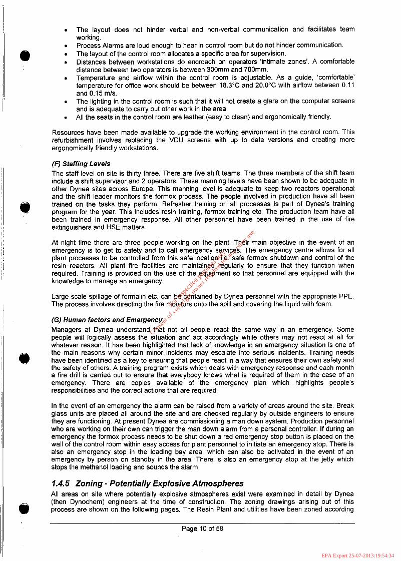
to the international standard IEC 79-1 0 “Classification of Hazardous Areas”. Under the ATEX Directive, Dynea are obliged to prepare a fire and explosion document. The Safety Report will be Dynea’s fire and explosion document. A full review of the zoning arrangements in line with the ATEX directive will be taking place and any changes to the zoning will be notified to all relevant parties. This zoning document will be included within the Safety Report. A consultant Safety Engineer has been commissioned to carry out this project. This project will be completed prior to the July 2006 deadline.
Q)
I
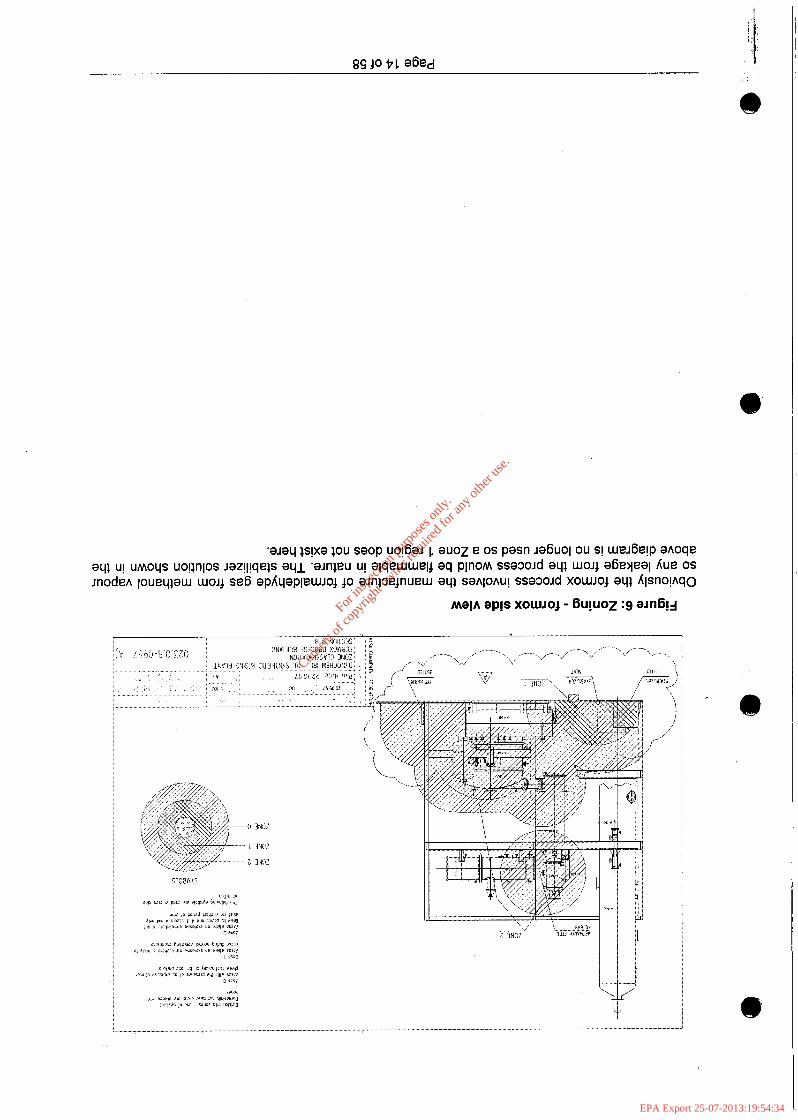
Figure 2: Zoning - reactors side view
The reactors are sealed vessels and a potentially explosive atmosphere could only occur outside them if manual charging of small volumes of, e.g. antifoam, were to take place during the batch process.
I Page 11 of 58 , 1:
For
insp
ectio
n pur
pose
s only
.
Conse
nt of
copy
right
owne
r req
uired
for a
ny ot
her u
se.
EPA Export 25-07-2013:19:54:34
1
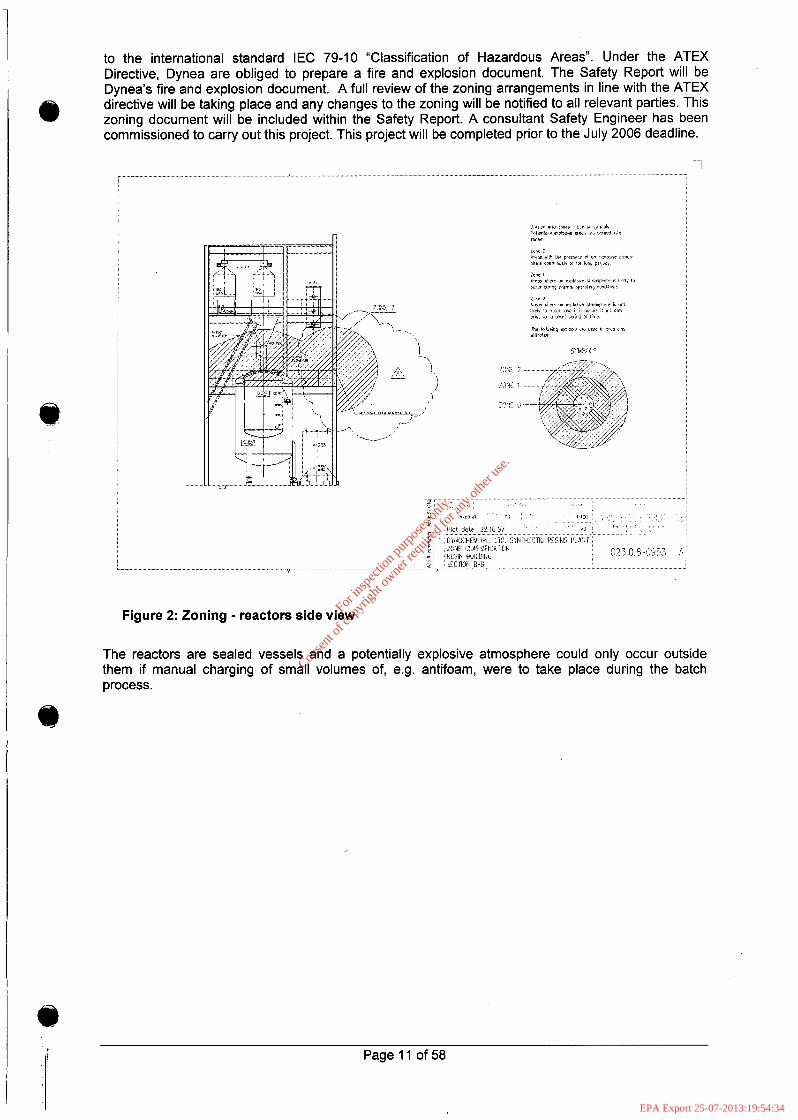
Figure 3: Zoning - reactors front view
. .... . .. ...
1 Irn &!
T
Figure 4: Zoning - reactors top view
Page 12 of 58
For
insp
ectio
n pur
pose
s only
.
Conse
nt of
copy
right
owne
r req
uired
for a
ny ot
her u
se.
EPA Export 25-07-2013:19:54:34
......
1 .......... "" - ............. *....-~~'... '*J .... ". X-.X.II.I.
.....................................................................
...............................................................................................................
I
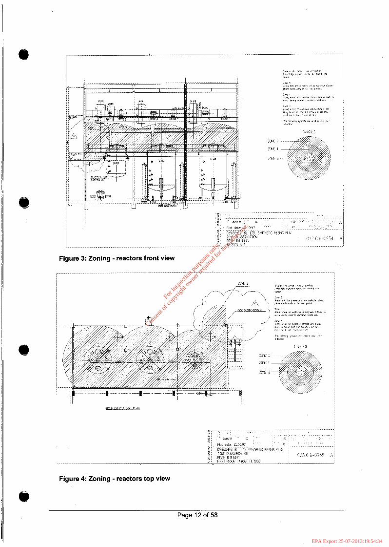
Figure 5: Zoning - reactors interior
The formalin charged to the reactors during the batch process contain approximately 1% methanol and this, along with the formaldehyde vapours, is what generates the potentially explosive atmosphere.
Page 13 of 58
For
insp
ectio
n pur
pose
s only
.
Conse
nt of
copy
right
owne
r req
uired
for a
ny ot
her u
se.
EPA Export 25-07-2013:19:54:34
a
I
For
insp
ectio
n pur
pose
s only
.
Conse
nt of
copy
right
owne
r req
uired
for a
ny ot
her u
se.
EPA Export 25-07-2013:19:54:34
\I ........ . . . .....
L
,.,'.
i
i: ,, ,.. ,,,, z 3 r a ;, /' ' ~- / ----i_,
... ~ . . .*A .__-, . . . . . . . . . . . . . . " ........... ............... . . . . . .
.................... .......
. .
For
insp
ectio
n pur
pose
s only
.
Conse
nt of
copy
right
owne
r req
uired
for a
ny ot
her u
se.
EPA Export 25-07-2013:19:54:34
. . . . . . . . . . ..o
i :
........ ............... ........ .................. ,/ . """" ............................. -1 r 7 t W
.* ..
. . .
I 1
e
For
insp
ectio
n pur
pose
s only
.
Conse
nt of
copy
right
owne
r req
uired
for a
ny ot
her u
se.
EPA Export 25-07-2013:19:54:34

L
Figure 11 : Zoning - methanol tank and loading area
The methanol tanker loading area is the area where methanol vapours are most likely to occur due to vessel venting and connecting/disconnecting of hoses. An automated fire and vapour detection system coupled to a fire suppression system will be installed by first quarter of 2006.
1.4.6 Location of Occupied Buildings Within Dynea the majority of staff are located in the controVoffice building which houses support functions such as quality control, accounts, engineering as well as the plant control room. The control room is located on the third floor of the administration building. Dynea have a Fire Safety Certificate (no. 95/BC/S/l216) for this building. This certificate was issued on the basis that the wall separating the control room from the formox process satisfied section 3.2.5.1 of the "Technical Guidance Document B, Fire" under article 5 of the Building Regulations, 1991. The requirement of section 3.2.5.1 is detailed below.
( 7 )
(2)
A building shall be so designed and constructed that, in the event of fire, its stability will be maintained for a reasonable period. A wall common to two or more buildings shall be so designed and constructed that it offers adequate resistance to the spread of fire between those buildings. A building shall be sub-divided with fire resisting construction where this is necessary to inhibit the spread of fire within the building. A building shall be so designed and constructed that the unseen spread of fire and smoke within concealed spaces in its structure or fabric is inhibited where necessary.
(a)
(b)
(3)
The bursting discs on the vapouriser and converter also offer increased protection during a fire or explosion situation
Page 17 of 58
For
insp
ectio
n pur
pose
s only
.
Conse
nt of
copy
right
owne
r req
uired
for a
ny ot
her u
se.
EPA Export 25-07-2013:19:54:34

Figure 12 shows a site map giving the locations of the main buildings etc as well as the numbers and locations of personnel.
dynes Dynea Ireland Limited, Marino Point
Scale approx. 1500 Do Not Scale
IFlPROPERlY
Figure 12: Site Map Showing Numbers of Personnel etc.
Areas of the site where a major accident hazard could occur on the site are marked with numbers on an orange background as follows:
1. 2. 3. 4.
The methanol storage tank, marked in red, is located at the south-west of the site. The resin production area located close to the centre of the site. The formaldehyde production (Formox) area to the East of No. 2 above. The formalin storage tanks, marked in yellow, are approximately in the centre of the site.
Escape routes to the assembly point are marked in solid light blue line. Alternate escape routes are in the dotted light blue line.
Appendix 8 includes a 3-0 drawing of the Dynea site with locations of buildings, storage tanks and emergency equipment.
e Description of Areas Where a Major Accident May Occur
The potential for a major accident to occur within the Dynea Ireland site relates to the following areas as identified from the major hazard identification study (i.e. PHA) described in Section 2.
Page 18 of 58
For
insp
ectio
n pur
pose
s only
.
Conse
nt of
copy
right
owne
r req
uired
for a
ny ot
her u
se.
EPA Export 25-07-2013:19:54:34
Methanol Bulk Storage
Formalin Manufacture
0 Formalin Bulk Storage
0 Resin Manufacture
A description is also given of the following areas which are central to Dynea activities.
0 Jetty Operations
0 TankFarm
0 Utilities
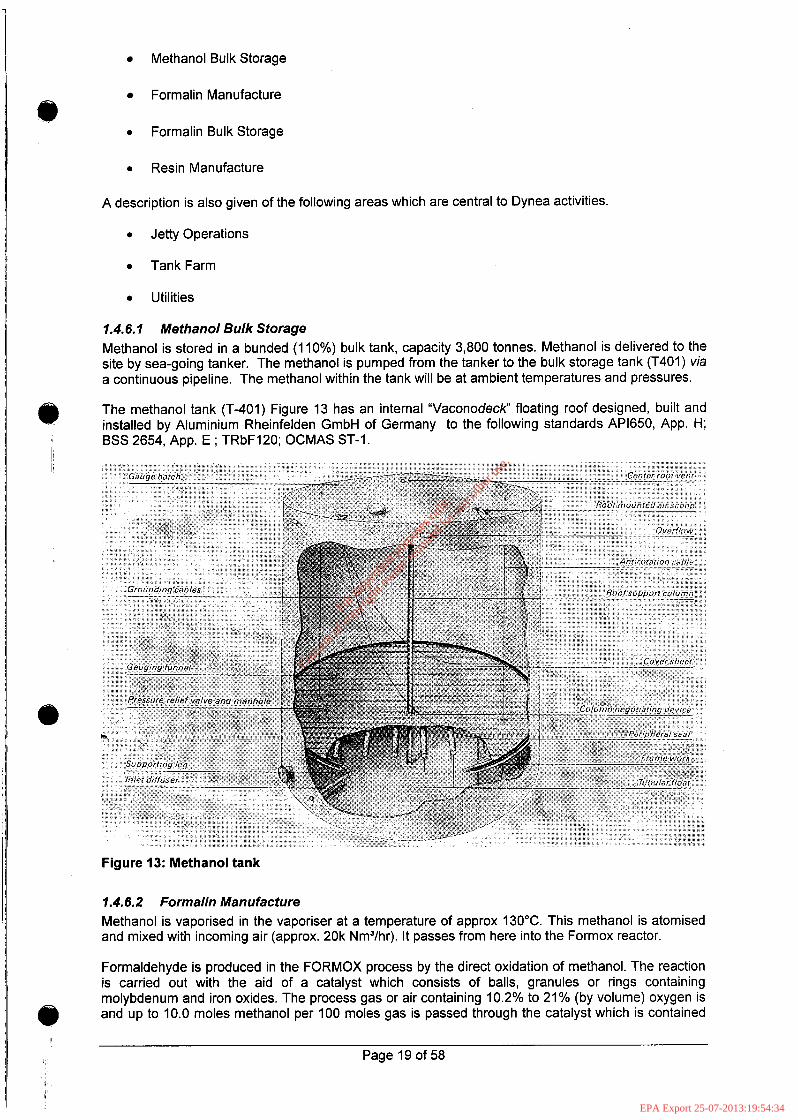
1.4.6.1 Methanol Bulk Storage Methanol is stored in a bunded (1 10%) bulk tank, capacity 3,800 tonnes. Methanol is delivered to the site by sea-going tanker. The methanol is pumped from the tanker to the bulk storage tank (T401) via a continuous pipeline. The methanol within the tank will be at ambient temperatures and pressures.
The methanol tank (T-401) Figure 13 has an internal “Vaconodeck“ floating roof designed, built and installed by Aluminium Rheinfelden GmbH of Germany to the following standards AP1650, App. H; BSS 2654, App. E ; TRbF120; OCMAS ST-1.
Figure 13: Methanol tank
1.4.6.2 Formalin Manufacture Methanol is vaporised in the vaporiser at a temperature of approx 130°C. This methanol is atomised and mixed with incoming air (approx. 20k Nm3/hr). It passes from here into the Formox reactor.
Formaldehyde is produced in the FORMOX process by the direct oxidation of methanol. The reaction is carried out with the aid of a catalyst which consists of balls, granules or rings containing molybdenum and iron oxides. The process gas or air containing 10.2% to 21% (by volume) oxygen is and up to 10.0 moles methanol per 100 moles gas is passed through the catalyst which is contained
Page 19 of 58
For
insp
ectio
n pur
pose
s only
.
Conse
nt of
copy
right
owne
r req
uired
for a
ny ot
her u
se.
EPA Export 25-07-2013:19:54:34
-
in a multiple tube unit called a converter where the reaction takes place. The first layer that the methanol/air stream comes into contact with in the tubes is a layer of non-reactive ceramic rings which would be at the same temperature as the Dowtherm oil - approx. 250°C. Dowtherm liquid serves as a heat transfer media in the converter. It both heats the air methanol mixture to the reaction temperature in the upper part of the catalyst tube and removes the heat of reaction in the lower part. The Dowtherm is operated at its boiling point, and the excess heat of reaction is carried away by the Dowtherm vapours which are condensed in the Dowtherm Condenser to produce high pressure steam for the process. The gas stream then passes onto the iron-molybdate catalyst rings and the reaction brings the temperature up to approx. 35O0C.-4OO0C (depending on the life stage of the catalyst and the throughput).
0
I
The gases which leave the converter are cooled in an aftercooler where low pressure steam is produced. The gas then enters an absorber where the formaldehyde is absorbed into water to produce up to 55% formaldehyde solution. The product solution contains small amounts of formic acid and unreacted methanol (less than 1%).
Each catalyst load operates for about 9 to 24 months, depending upon the production rate per tube. Higher production rates per tube cause the catalyst to lose activity faster and give a shorter catalyst life. Lower production rates per tube will give a longer catalyst life. The maximum production rate of the plant cannot be reached for about 5 to 10 days after a catalyst change. The catalyst continually loses its activity during the run, and it finally must be dumped and reloaded when too much unreacted methanol passes through the reactor.
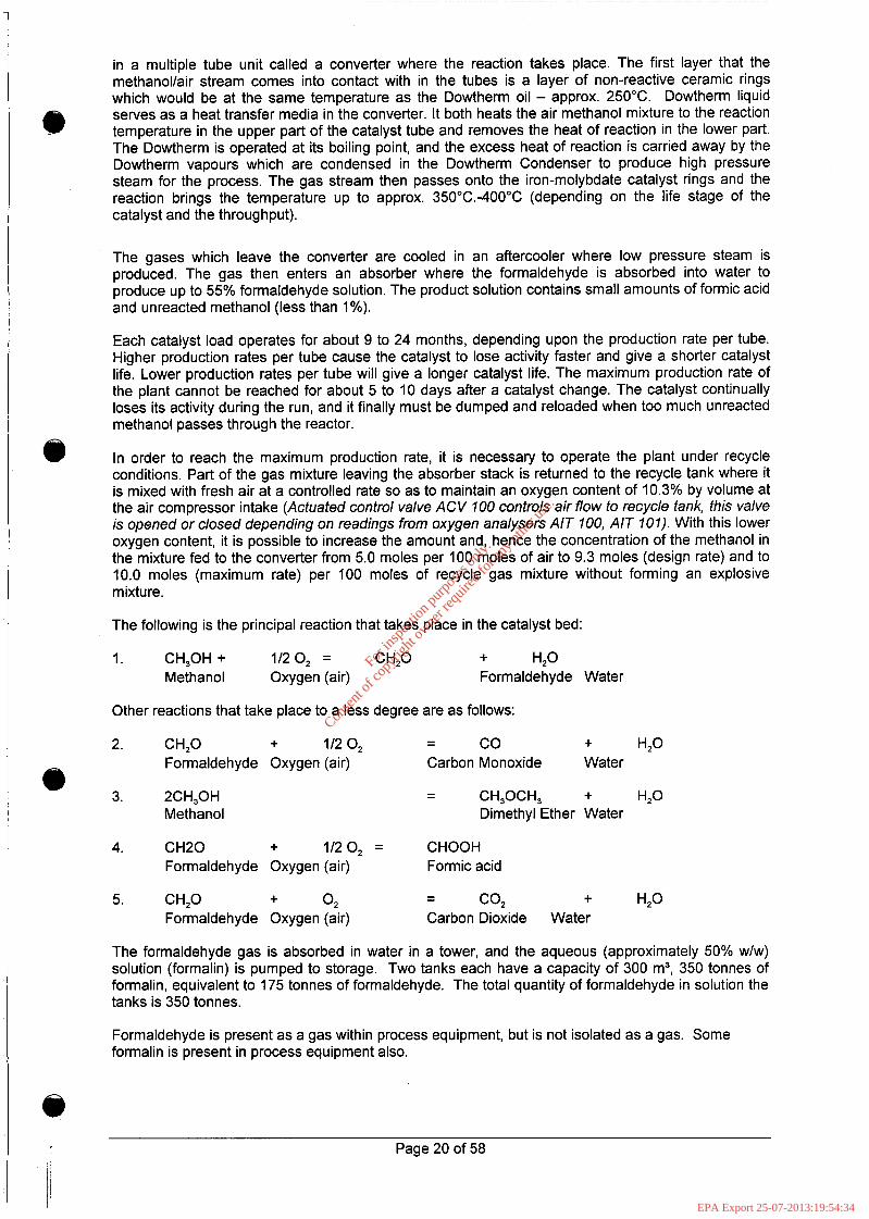
In order to reach the maximum production rate, it is necessary to operate the plant under recycle conditions. Part of the gas mixture leaving the absorber stack is returned to the recycle tank where it is mixed with fresh air at a controlled rate so as to maintain an oxygen content of 10.3% by volume at the air compressor intake (Actuated control valve ACV 100 controls air flow to recycle tank, this valve is opened or closed depending on readings from oxygen analysers AlT 100, AlT 101). With this lower oxygen content, it is possible to increase the amount and, hence the concentration of the methanol in the mixture fed to the converter from 5.0 moles per 100 moles of air to 9.3 moles (design rate) and to 10.0 moles (maximum rate) per 100 moles of recycle gas mixture without forming an explosive mixture.
The following is the principal reaction that takes place in the catalyst bed:
1. CH,OH + 1/2 0, = CH,O + H,O Methanol Oxygen (air) Formaldehyde Water
Other reactions that take place to a less degree are as follows:
CO + H2O 2. CH,O + 1/2 0, -
3. 2CH,OH - CH,OCH, + H2O
- Formaldehyde Oxygen (air) Carbon Monoxide Water
- Q Methanol Dimethyl Ether Water
4. CH20 + 1/20, = CHOOH Formaldehyde Oxygen (air) Formic acid
5. CH,O + 0, CO2 + H2O - - Formaldehyde Oxygen (air) Carbon Dioxide Water
The formaldehyde gas is absorbed in water in a tower, and the aqueous (approximately 50% w/w) solution (formalin) is pumped to storage. Two tanks each have a capacity of 300 m3, 350 tonnes of formalin, equivalent to 175 tonnes of formaldehyde. The total quantity of formaldehyde in solution the tanks is 350 tonnes.
Formaldehyde is present as a gas within process equipment, but is not isolated as a gas. Some formalin is present in process equipment also.
Page 20 of 58
For
insp
ectio
n pur
pose
s only
.
Conse
nt of
copy
right
owne
r req
uired
for a
ny ot
her u
se.
EPA Export 25-07-2013:19:54:34

e i '
For
insp
ectio
n pur
pose
s only
.
Conse
nt of
copy
right
owne
r req
uired
for a
ny ot
her u
se.
EPA Export 25-07-2013:19:54:35
1.4.6.3 Formalin Bulk Storage Formalin solution 55% concentration is pumped to two designated tanks (T402, T403) in the tank farm. These tanks are made of 304L Austenitic Stainless Steel. These tanks have a capacity of 300m3 .The tanks supply the reactors with formalin at approximately 50% concentration .The dilution is carried out using distillate produced (waste) during resin manufacture. The tanks are lagged and are kept at a temperature of 50 degrees C, this is to prevent the formation of paraformaldehyde. The vents from each of the formalin tanks are fed into a scrubber system which removes formaldehyde vapours to the distillate tank (T408). This vent is tested bimonthly for formaldehyde content, methanol and Dimethyl ether. The bund will contain the contents of a formalin tank however some of the formalin will splash onto the roadway during a catastrophic failure of the tank. This will be contained within the confines of the site. A process flow diagram of the formalin tanks is given in Appendix 11
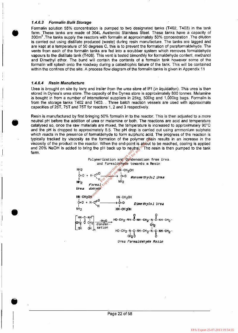
1.4.6.4 Resin Manufacture Urea is brought on site by lorry and trailer from the urea store at IF1 (in liquidation). This urea is then stored in Dynea's urea store. The capacity of the Dynea store is approximately 800 tonnes. Melamine is bought in from a number of international suppliers in 25kg, 500kg and 1,000kg bags. Formalin is from the storage tanks T402 and T403. . Three batch reaction vessels are used with approximate capacities of 25T, 75T and 75T for reactors 1, 2 and 3 respectively.
Resin is manufactured by first bringing 50% formalin in to the reactor. This is then adjusted to a more neutral pH before the addition of urea or melamine or both. The reactions are acid and temperature catalysed so, once the raw materials are mixed, the temperature is increased to approximately 90°C and the pH is dropped to approximately 5.5. The pH drop is carried out using ammonium sulphate which reacts in the presence of formaldehyde to form sulphuric acid. The progress of the reaction is typically tracked by viscosity as the formation of the polymer chain results in an increase in the viscosity of the product in the reactor. When the end-point is about to be reached, cooling is applied and 20% NaOH is added to bring the pH back up to neutral. The resin is then pumped to the tank farm.
@
Palymerizatian and ibndensation fram Urea and Formaldehyde towards a Resin
NH 2 HN -CHzQH I I
I H + '-'Zo- p" MJt70r'tE&~l03 UfEa 2 "2 Formal -
Urea debyn'e
For
insp
ectio
n pur
pose
s only
.
Conse
nt of
copy
right
owne
r req
uired
for a
ny ot
her u
se.
EPA Export 25-07-2013:19:54:35
Should the end point be missed for human error, process or raw material reasons there is the risk of the production "gelling". This entails the curing of the resin in the reactor resulting in a solids mass which must be dug out and sent to landfill. This material is classified as non-hazardous.
A number of systems are in place to prevent this happening, including regular pH and viscosity checks, ampere measurement alarms on the reactor agitators (high amp readings with increased viscosity) and caustic dump tanks to allow NaOH to be added rapidly to the reactors to stop the reaction.
0
The reactors are protected against the effects of overpressure by bursting disks. The bursting disk set pressure depends on the duty of the reactor, but is a maximum of 2.41 bar abs. at 12OoC.
The urea - formaldehyde methylolation reaction is weakly exothermic: - 6 kcal/mole. Less data is available for melamine, but it is even less exothermic. For a conservative estimate one may use the same figures as for urea - formaldehyde.
The Dynea Technical Centre in Lillestrsm have enclosed some of the literature on UF reactions to show the rate dependence of pH and temperature and this is given below:
Page 23 of 58
For
insp
ectio
n pur
pose
s only
.
Conse
nt of
copy
right
owne
r req
uired
for a
ny ot
her u
se.
EPA Export 25-07-2013:19:54:35

'? ' I-
Page 24 of 58
For
insp
ectio
n pur
pose
s only
.
Conse
nt of
copy
right
owne
r req
uired
for a
ny ot
her u
se.
EPA Export 25-07-2013:19:54:35

For
insp
ectio
n pur
pose
s only
.
Conse
nt of
copy
right
owne
r req
uired
for a
ny ot
her u
se.
EPA Export 25-07-2013:19:54:35

Methanol Tanker Loading
Methanol is filled into road tankers from the methanol bulk storage tank (T401). These tankers are shipped to (predominantly) the pharmaceutical industry within the Munster region.
The methanol loading area is fully bunded and the drain automatically transfers to the adjacent methanol tank bund in times of rainfall or spillage.
The methanol tanker is dropped in the loading bay by an approved tractor unit and the tractor unit then withdraws from the bay. The tanker is then connected to an earthing system which automatically both makes and proves the earth. Unless this shows that an earth has been made then the methanol transfer pumps cannot start.
The hose, fitted with a non-drip connecting fitting, is connected to the tanker which is also fitted with one of these fittings. The operator keys into the flowmeter the quantity to be transferred and starts the operation. The operation is monitored at all times by the operator who remains in the bay. When the flowmeter cuts out the pumps the operator disconnects the hose from the tanker.
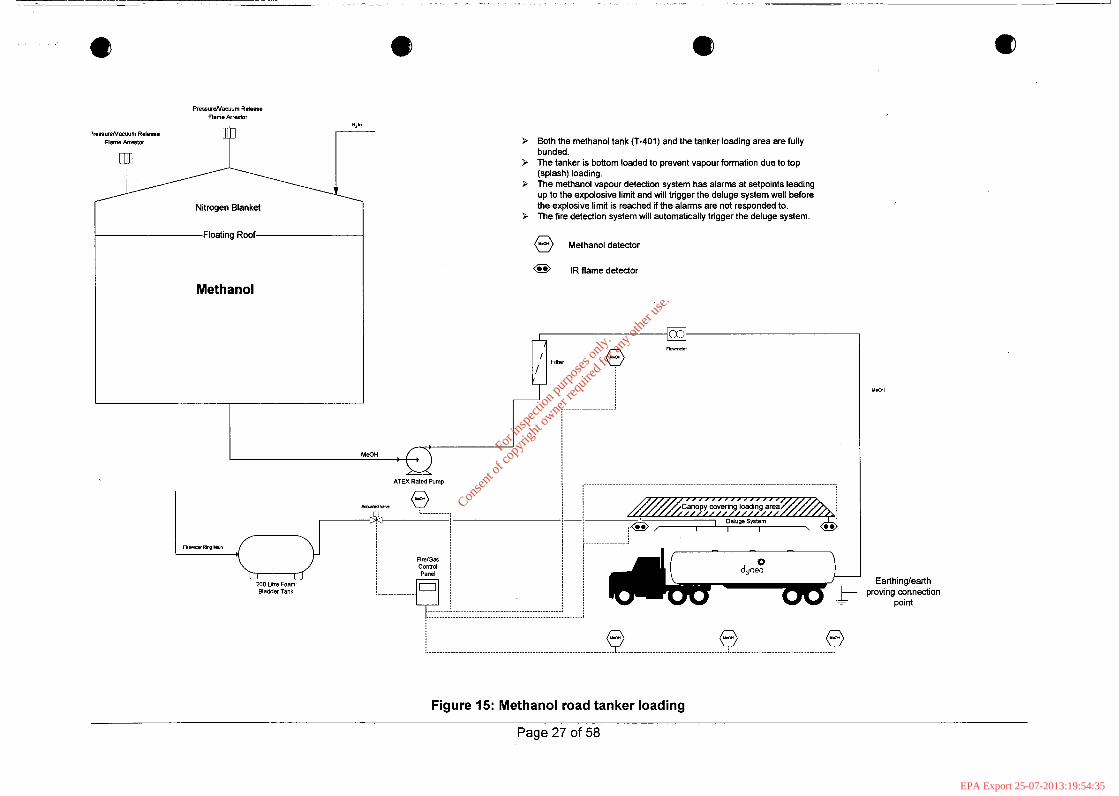
The loading bay is fitted with methanol vapour detectors and a flame detection system. Both of these systems trigger the foam deluge system mounted in the canopy over the bay which will cover the area in an alcohol resistant fire fighting foam. The process is shown in
Figure 15 below.
@
8 Page 26 of 58
For
insp
ectio
n pur
pose
s only
.
Conse
nt of
copy
right
owne
r req
uired
for a
ny ot
her u
se.
EPA Export 25-07-2013:19:54:35
Nitrogen Blanket
Floating Roof
Methanol
> Both the methanol tank (T-401) and the tanker loading area are fully bunded.
3 The tanker is bottom loaded to prevent vapour formation due to top (splash) loading.
3 The methanol vapour detection system has alarms at setpoints leading up to the expolosive limit and will trigger the deluge system well before the explosive limit is reached if the alarms are not responded to.
3 The fire detection system will automatically trigger the deluge system.
@ Methanol detector
@ IR flame detector
I MeOH
ATEX Rated Pump
Filler I L:. Rr- Rbq L1.i"
200 btre Foam Bladder Tank
Canopy covering loading area //////////////// ,
I I I , 0.' 1 DeluwSystem
j 0. ,
+ A I M
Earlhinglearth dyfiea
proving connection point
.... i
Figure 15: Methanol road tanker loading
Page 27 of 58
For
insp
ectio
n pur
pose
s only
.
Conse
nt of
copy
right
owne
r req
uired
for a
ny ot
her u
se.
EPA Export 25-07-2013:19:54:35
1.4.6.4. I Vessel Specifications Specifications for vessels associated with the Formox and Resin manufacturing processes are given through the following Tables.
Page 28 of 58
For
insp
ectio
n pur
pose
s only
.
Conse
nt of
copy
right
owne
r req
uired
for a
ny ot
her u
se.
EPA Export 25-07-2013:19:54:35
Limerick A-107 1 Recycle Tank bapphire Engineering, Co.
[Limerick A-108 I Dowtherm bteliers Geens PVBA, Belgium I Carbon Steel to DIN 17155 HI1 I ASME Vlll l l I AIB-Vinqotte
Stainless Steel - 304L BS 5500 Const. Cat 2 British Engine Insurance
A-109 A-303
Seal Pot Steam Boiler
Dowtherm Condenser
~~
H-101
Ateliers Geens PVBA, Belgium Carbon Steel to DIN 17155 HI1 ASME VIII/l AIB-Vin~otte Beel Industrial Boilers, Lincoln, Carbon Steel BS 2790 1992 Class 1 British Engine Insurance England Ateliers Geens PVBA, Belgium Stainless Steel - 304L ASME VIII/l AIB-VinGotte
H-102 H-301
- - . . - - . . - - . Aftercooler Excess Steam
~
T-30 1
Ateliers Geens PVBA, Belgium Stainless Steel - 304L ASME VIII/l AIB-Vin~otte Alcards, Sweden SS 1430, SS 1312 ASME VIII/I SAQ - Swedac Ackreditering
Condenser Condensate Tank
Ateliers Geens PVBA, Belgium Carbon Steel to DIN 17155 HI1 ASME VIII/l AI B-VinGotte
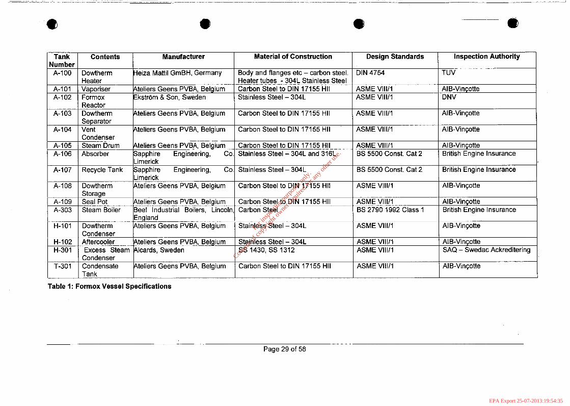
Table 1: Formox Vessel Specifications
Page 29 of 58
For
insp
ectio
n pur
pose
s only
.
Conse
nt of
copy
right
owne
r req
uired
for a
ny ot
her u
se.
EPA Export 25-07-2013:19:54:35
A-I 05 Tube - 4.5 Bar 5 Bar Shell - 0.5 Bar Gauge Tube - 5.5 Bar Gauge 2.0 BarG + F.V. Shell-1.1 Bar
I-H-lO1 - _
Tube - 6.75 Bar 7.5 Bar 160°C 3.8 BarGauge 160°C Shell - 0.8 Bar Gauge Tube - 8.25Bar Gauge Tube - 155°C Tube - 3.8 Bar Gauge Tube - 148°C 2.65 Bar Gauge + S.H 0-50°C 0.25 Bar Gauge 25°C Shell - 1.65 Bar Shell - 300°C Shell - 0 Bar Gauae Shell - 25°C
Tube - 300°C
Shell - 150°C
Tube - 0- 1 Bar Gauge
Shell - 0.28 Bar Gauge
Tube - 70°C
Shell - 67°C
H-211 H-301
T-30 1
Tube - 5 Bar 3 Bar 10.86 Bar Shell - 23 Bar Tube - -0.5/3 Bar Shell - 5 Bar
Contents
Tube - 7.5 Bar Tube - 150°C Tube - 5 Bar Gauge Tube - 160°C 4.5 Bar 400°C 0-1 Bar Gauge 214°C 16.31 Bar 10 Bar Gauge 185°C 200°C Shell - 35.25 Bar Shell - 220°C Shell - 18.5Bar Gauge Shell - 212°C Tube - 4.5 Bar Tube - 400°C Tube - 1 Bar Gauge Tube - 260°C Shell - 7.5 Bar Shell - 180°C Shell - 5 Bar Gauae Shell - 160°C
Dowtherm Heater
Tube- 3 Bar -116 Bar Gauge Shell - 15 Bar
Vaporiser
Tube - 4.5 Bar Tube - 400°C Tube - 2 Bar gauie Tube - 160°C 9 Bar Gauge 125°C 0 Bar gauge 40°C Shell - 23 Bar Shell - 225°C Shell - 1 OBar Gauge Shell - 185°C
Formox Reactor
Tube- 10 Bar -1/1 Bar
Dowtherm Separator Vent Condenser
Tube - 15 Bar Tube - 184°C Tube - 10Bar Gauge Tube - 185°C 3 Bar 116°C 0 Bar Gauge 90°C
Steam Drum Absorber
Recycle Tank Dowtherm Storage
- - - . - - - -
Seal Pot Steam Boiler Dowtherm Condenser
Aftercooler
Condenser Excess Steam Condenser
Condensate Tank
Design Pressure I Test Pressure 1 Design I Operating Pressure I Operating I Temperature 1 I Temperature
10 Bar I 13 Bar I300"C I 2 Bar aauae 1250°C U - - ~~
Shell - 5 Bar I Shell - 7.5 Bar I Shell - 180°C I Shell - 3.8 Bar Gauge 1 Shell - 160°C Tube - 3 Bar Shell - 3 Bar Gauge
I Tube - 4.5 Bar I Shell - 4.9 Bar Gauae
I Tube - 180°C I Shell - 400°C
I Tube - 0.28 Bar Gaige I Tube - 130°C I Shell - 0-1 Bar Gauae I Shell - 260°C
Tube - 3 Bar Gauge 3 Bar 1 4.5Bar 1400°C I 0-1 BarGauae I 260°C
I Tube - 4.9 Bar Gauge I Tube - 400°C I Tube - 0.28 Bar Gaige I Tube - 360°C _ _ - - - - - - . - -
Shell - -0.513 Bar I Shell - 6 Bar I Shell - 350°C I Shell - 0-1 Bar Gauge I Shell - 70°C
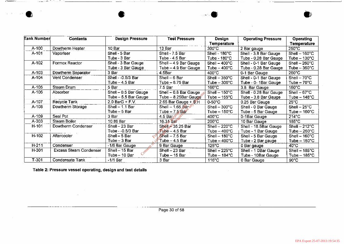
Table 2: Pressure vessel operating, design and test details
Page 30 of 58
For
insp
ectio
n pur
pose
s only
.
Conse
nt of
copy
right
owne
r req
uired
for a
ny ot
her u
se.
EPA Export 25-07-2013:19:54:35

Tank Jumber A-207
A-211
A-22 1
A-23 1
A-303
H-102
T-208
Air Receiver Air Receiver R I NaOH Dump Tank R2 NaOH Dump Tank R3 NaOH Dump Tank
T-301 ._ ._ - - - T-366 T-368 ..- __
N/A
N/A
N/A
17155 HI1 A.J. Metal Products, UK Carbon Steel BS 5169 Class 2 Grade C Lloyds Insurance Cool Technology, England Carbon Steel BS 5169 Class 2 Grade C Lloyds Insurance Sapphire Engineering, Co. Galvanised, Coated ASME VI11/1 Lloyds Limerick Carbon steel CMBB, Italy Galvanised, Coated ASME VIII/I ISPESL
Carbon steel CMBB, Italy Galvanised, Coated ASME VIII/I ISPESL
Carbon steel
(b
Inspection Authority
British Engine Insurance
British Engine Insurance
British Engine Insurance
British Engine Insurance
British Engine Insurance
AIB-Vincotte
Manufacturer
AI B-Vincotte
Table 3: Vessels associated with Reactors
Page 31 of 58
For
insp
ectio
n pur
pose
s only
.
Conse
nt of
copy
right
owne
r req
uired
for a
ny ot
her u
se.
EPA Export 25-07-2013:19:54:35
Tank Number Contents
A-231 Reactor 3
Shell - 0 Bar Gauge Tube - 10 Bar' Gauge
Shell - OBar Gauge Tube - 10 Bar Gauge
A-303 I Steam Boiler N/A I R1 NaOH
Shell - 80°C Tube-185°C
Shell - 80°C Tube-185°C
Design Pressure
Vessel - 2.5 Bar Gauge + F.V. Jacket - 11 Bar Gauge + F.V. Vessel - 2.5 Bar Gauge + F.V. Jacket - 11.5 Bar Gauge + F.V. Vessel - 2.5 Bar Gauge+ F.V. Jacket - 11 Bar Gauge + F.V. 10.86 Bar -1/3 Bar Gauge
A-22 1
11 Bar Gauge
Reactor 2 Capacity 60m3
11 Bar Gauge 0 Bar Gauge
Test Pressure
20°C
Vessel - 4.18 Bar Gauge + S.H. Jacket - 19.5 Bar Gauge.
Vessel - 4.38 Bar Gauge + S.H. Jacket - 19.5 Bar Gauge.
Vessel - 4.38 Bar Gauge + S.H. Jacket - 19.5 Bar Gauge
16.31 Bar 5 Bar gauge
16.5 Bar Gauge
16.5 Bar Gauge
Design Temperature
Vessel - 0-1 50°C Jacket - 0-200°C
Vessel - 0-1 50°C Jacket - 0-200°C
Vessel - 0-1 50°C Jacket - 0-200°C
200°C -1/+50"C
-1 0/+50"C
-1 0/+50"C
Gauge
185°C 0 Bar Gauge
I
0 Bar Gauge 120°C
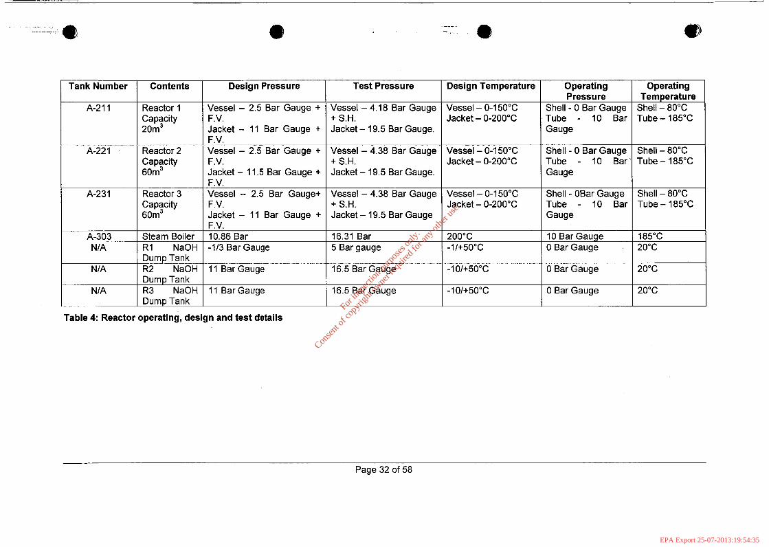
Table 4: Reactor operating, design and test details
Page 32 of 58
For
insp
ectio
n pur
pose
s only
.
Conse
nt of
copy
right
owne
r req
uired
for a
ny ot
her u
se.
EPA Export 25-07-2013:19:54:35
Dynea Ireland Limited Standard Operating Procedure Control of Major Accident Hazards Involving Dangerous Substances Regulations Safety Report Document Number: 1.0.3 Revision: Issue Date:1/12/05
I
dynea rc 3 6
1.4.6.4.2 Pipeline Specification The standards to which the pipelines are constructed are to ASME 831.3. The requirement for piping according to ASME B 31.3 is detailed in Appendix 24. Pipelines are painted to prevent corrosion and are inspected regularly.
1.4.6.5 Standards Review Dynea Technical Centre Norway is responsible for reviewing the present standards of pipe work, equipment design and plant design to ensure they meet current best practice. Dynea Corporate are developing market share year in year out which necessitates building new plants. This system ensures that the latest standard reviews are incorporated in new plants. Standards that were used in Dynea Ireland plant construction may have changed during the last 10 years. If these changes have safety and environmental implications Technical Centre will notify Dynea Ireland of the required changes. This ensures that the latest information regarding best practice is implemented at Dynea Ireland. e
Page 33 of 58
For
insp
ectio
n pur
pose
s only
.
Conse
nt of
copy
right
owne
r req
uired
for a
ny ot
her u
se.
EPA Export 25-07-2013:19:54:35
@
I ’ i
Dynea Ireland Limited Standard Operating Procedure Control of Major Accident Hazards Involving Dangerous Substances Regulations Safety Report Document Number: 1.0.3 Revision: Issue Date:1/12/05
3 dynea
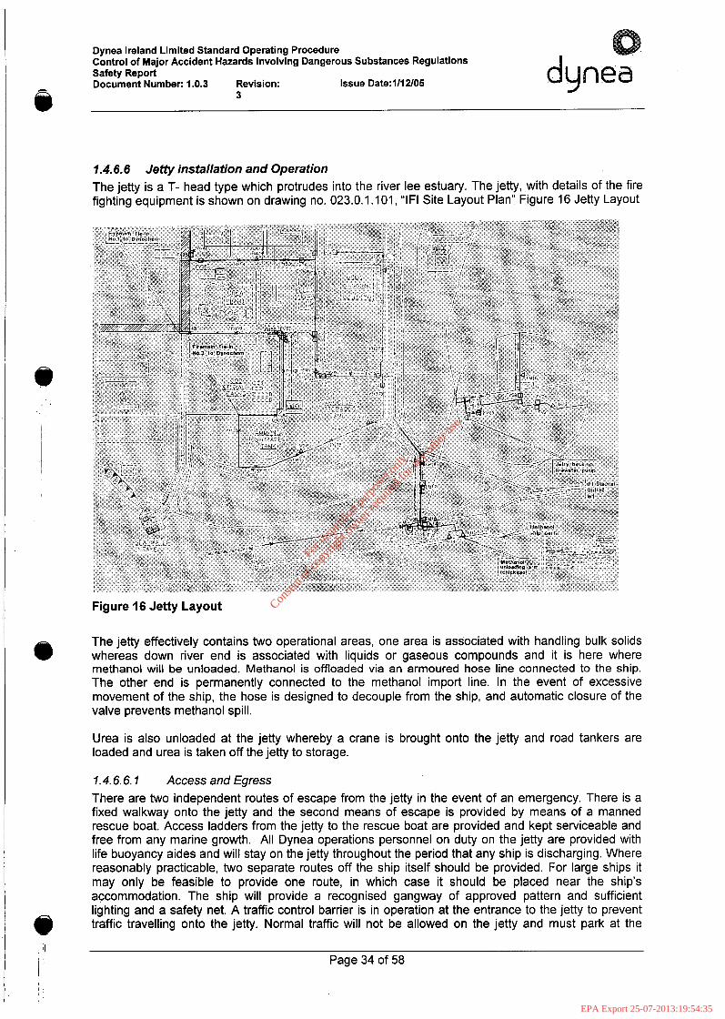
1.4.6.6 Jetty installation and Operation The jetty is a T- head type which protrudes into the river lee estuary. The jetty, with details of the fire fighting equipment is shown on drawing no. 023.0.1.101, “IF1 Site Layout Plan” Figure 16 Jetty Layout
Figure 16 Jetty Layout
The jetty effectively contains two operational areas, one area is associated with handling bulk solids whereas down river end is associated with liquids or gaseous compounds and it is here where methanol will be unloaded. Methanol is offloaded via an armoured hose line connected to the ship. The other end is permanently connected to the methanol import line. In the event of excessive movement of the ship, the hose is designed to decouple from the ship, and automatic closure of the valve prevents methanol spill.
Urea is also unloaded at the jetty whereby a crane is brought onto the jetty and road tankers are loaded and urea is taken off the jetty to storage.
1.4.6.6.1 Access and Egress There are two independent routes of escape from the jetty in the event of an emergency. There is a fixed walkway onto the jetty and the second means of escape is provided by means of a manned rescue boat. Access ladders from the jetty to the rescue boat are provided and kept serviceable and free from any marine growth. All Dynea operations personnel on duty on the jetty are provided with life buoyancy aides and will stay on the jetty throughout the period that any ship is discharging. Where reasonably practicable, two separate routes off the ship itself should be provided. For large ships it may only be feasible to provide one route, in which case it should be placed near the ship’s accommodation. The ship will provide a recognised gangway of approved pattern and sufficient lighting and a safety net. A traffic control barrier is in operation at the entrance to the jetty to prevent traffic travelling onto the jetty. Normal traffic will not be allowed on the jetty and must park at the
Page 34 of 58
For
insp
ectio
n pur
pose
s only
.
Conse
nt of
copy
right
owne
r req
uired
for a
ny ot
her u
se.
EPA Export 25-07-2013:19:54:35
Dynea Ireland Limited Standard Operating Procedure Control of Major Accident Hazards Involving Dangerous Substances Regulations Safety Report Document Number: 1.0.3 Revision: Issue Date:1/12/05 dynea
3
1 entrance to the jetty before the barrier. If a vehicle is required to travel onto the jetty, the vehicle r
should be controlled by means of a Hot Work Permit issued through the Dynea supervisor. For Emergency vehicles a Hot Work Permit shall not be considered necessary. For these situations the Dynea supervisor shall give clearance either verbally or by radio.
1.4.6.6.2 Ship- shore communication Effective communication should be maintained between the ships deck watch and Dynea personnel so that transfer of cargo is safely controlled. Dynea Ireland Ltd will provide communication equipment. The radio system is a Motorola system with Eurobase repeater and PABX connectivity through a Zetron Model 735 telephone patch. The radios used are Ex rated Motorola GP900Ex. People who can readily contact senior staff and if necessary commence emergency procedures continuously man telephones and radios.
1.4.6.6.3 Mooring of Vessels The minimum mooring line requirements for vessels over 750 DVVT are as follows: - 3 Head lines. 3 stern lines and a back spring line fore and aft.
I ’ ~ I
i Any ships whilst alongside the jetty shall provide emergency towing wireshopes of sufficient length to reach the waters edge with an eye on the outboard end made fast to the vessels bitts on the offshore bow and quarter. A notice board shall be displayed in a prominent position near to the access to the ship indicating “No Admittance Except on Business, No Smoking Allowed” (Smoking will not be allowed on deck or in the operation area).
I
1.4.6.6.4 Mobility of Ships While berthed, a ship should be prepared to move away at short notice, tidal conditions permitting. This will normally mean that the engines, steering gear and other manoeuvring equipment should be kept ready for use. The captain shall at all times remain on board with sufficient crew to work and move the vessel.
1.4.6.6.5 Prior to the ships arrival Dynea personnel will carry out the following:
Unloading and Discharge of Methanol
Ensure Ammonia/Methanol selector switch in control room on jetty is set to Methanol position. Ensure that mobile foam unit is positioned on Jetty and powered up. Ensure IBC drain unit is positioned on Jetty Check out instrument air supply and test SP 2705 and SP2703 valves. Test Fire Water Pump. Check out Methanol Line for any damage. Operate 2703-L Loading Arm and observe for any defects. Check Phone Communications from Jetty to Dynea Control room. Check Rope Winch equipment at eastern end of jetty. Operations Personnel to check their own PPE i.e.
o Chemical Splash Suit o Wellington Boots o P VC Gauntlets o Canister Mask with multi purpose filter
Before commencement of discharging the Dynea supervisor will accompany the Master or Chief Officer on a tour of the vessel to familiarise himself with the layout of equipment, valves, relief valves, etc., and to carry out inspections to ensure that all safety regulations are being observed. A safety checklist is completed between Dynea supervisor and a representative from the ship. Before discharging operations begin all lines not in use and connected to the cargo system shall be closed and blanked off. Immediately after discharging has commenced a responsible ship’s officer shall make an inspection to ensure that there are no leaks. He shall make a similar inspection periodically throughout the loading or discharging operation. Prior to discharging, the maximum discharging rate
Page 35 of 58
@
I
For
insp
ectio
n pur
pose
s only
.
Conse
nt of
copy
right
owne
r req
uired
for a
ny ot
her u
se.
EPA Export 25-07-2013:19:54:36

Dynea Ireland Limited Standard Operating Procedure Control of Major Accident Hazards Involving Dangerous Substances Regulations Safety Report Document Number: 1.0.3 Revision: Issue Date:1/12/05
I
dynea d 3 0
and pressure shall be agreed between the master and the Dynea Supervisor bearing in mind the product temperature, the size and capacity of the ship's cargo lines, the ship's pumping capacity for off loading Methanol. In no circumstances shall any attempt be made to reduce the rate of off-loading from shore by closing any shore valve. Tripping of quick closing valves with a response time less than or equal to 5 seconds is not permitted. If cargo transfer has to be interrupted all discharge pumps shall be stopped and isolation valves closed on the jetty and ship. Any cargo spillage shall be reported to the Dynea Supervisor.
All pipes, valves, connections and fittings, etc., used for handling cargo, shall be kept free from leakage.
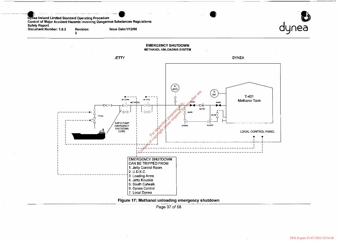
A high level alarm on T401 (Methanol Storage Tank at Dynea) will trip SP 2705 and SP2703 at the Jetty. It will also activate the Klaxon Alarm at the Jetty. Immediately the ship must stop their pumps. The actual valves and set up are given in Figure 17 below.
i
1 !I; Page 36 of 58 / I 1 II
For
insp
ectio
n pur
pose
s only
.
Conse
nt of
copy
right
owne
r req
uired
for a
ny ot
her u
se.
EPA Export 25-07-2013:19:54:36
- - 8 ._ - e ea Ireland Limited Standard Operating Procedure Control of Major Accident Hazards Involving Dangerous Substances Regulations Safety Report Document Number: 1.0.3 Revision: Issue Date:1/12/05
3
1
duma J
EMERGENCY SHUTDOWN METHANOL UNLOADING SYSTEM
JETTY DYNEA
T-40 1 Methanol Tank
481% % 4824E
RV4E86 RV-7
LOCAL CONTROL PANEL
T T I I
I I
I I I I I I I L- . _ . _
I
EMERGENCY SHUTDOWN CAN BE TRIPPED FROM 1. Jetty Control Room 2. U.D.E.C 3. Loading Arms 4. Jetty Knuckle 5. South Catwalk 6. Dynea Control 7. Local Dynea
Figure 17: Methanol unloading emergency shutdown
Page 37 of 5%
For
insp
ectio
n pur
pose
s only
.
Conse
nt of
copy
right
owne
r req
uired
for a
ny ot
her u
se.
EPA Export 25-07-2013:19:54:36
Dynea Ireland Limited Standard Operating Procedure Control of Major Accident Hazards Involving Dangerous Substances Regulations Safety Report Document Number: 1.0.3 Revision: Issue Date:1/12/05
3
1.4.6.6.6 Unloading and Discharge of Urea
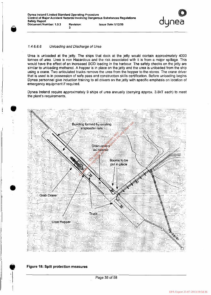
Urea is unloaded at the jetty. The ships that dock at the jetty would contain approximately 4000 tonnes of urea. Urea is non Hazardous and the risk associated with it is from a major spillage. This would have the effect of an increased BOD loading in the harbour. The safety checks on the jetty are similar to unloading methanol. A hopper is in place on the jetty and the urea is unloaded from the ship using a crane. Two articulated trucks remove the urea from the hopper to the stores. The crane driver that is used is in possession of safe pass and construction skills certification. Before unloading begins Dynea personnel give induction training to all drivers on the jetty with specific emphasis on location of emergency equipment if required.
Dynea Ireland require approximately 9 ships of urea annually (carrying approx. 3.8kT each) to meet the plant's requirements.
@ Figure 18: Spill protection measures
Page 38 of 58
For
insp
ectio
n pur
pose
s only
.
Conse
nt of
copy
right
owne
r req
uired
for a
ny ot
her u
se.
EPA Export 25-07-2013:19:54:36
Dynea Ireland Limited Standard Operating Procedure Control of Major Accident Hazards Involving Dangerous Substances Regulations Safety Report Document Number: 1.0.3 Revision: Issue Date:1/12/05
I
dynea J 3 U
1
The rails and their supporting concrete for the old urea shiploader provide bunding along the length of the jetty where the ship is docked. All drains on the jetty, where there is a risk of urea entering, are blocked to prevent contamination of the receiving waters. Booms are put in place to cover the section between the end of the rails and the jetty approach where urea might be washed into the river by rain etc. Adequate spill control measures - brushes, shovels, bags etc. - and dedicated cleaning personnel are present to allow the immediate clean up of any spillages which might occur, e.g. overspill form the hopper when the grab crane bucket opens.
Spills, if they occur, are brushed up by hand and shovelled into bags for transportation to the Dynea site for reworking.
Before the ship docks, the grab crane and hopper are brought into position. The ship docks at the jetty where trained Dynea personnel are in attendance. Once the hold has been inspected by Dynea appointed surveyors, and samples taken as needed, the unloading operation can begin. The grab crane begins unloading into the hopper. The bucket of the crane takes approximately 4T per grab. The unloading operation is carried out in a manner which minimises the creation of dust. From observing previous unloading operations at other locations where strict controls were not in place it could be seen that creation of dust was minimal. Dynea eliminates, as far as possible, the creation of dust during the offloading operation. The bucket on the crane is lowered into the hopper so that the urea is not dropped from a height etc.
Figure 19 gives the movement of traffic on and off the jetty. 4 rigid trucks are used in rotation with one being filled at all times and the other in various stages of the journey to and unloading in the urea store. Trucks drive onto the jetty via the jetty approach and turn left at the end of the approach, onto the jetty. They then wait until the previous truck has left the jetty when they reverse under the hopper to be filled. All trucks are fitted with tarpaulin covers which are closed as soon as the truck pulls away from the hopper and remain closed until the truck reaches the former IF1 (in liquidation) urea store.
Dynea personnel carefully supervise truck movement on and off the jetty.
The trucks go into the IF1 (in liquidation) urea store where they discharge their loads. As the trucks involved are tipper trucks and offloading is carried out within the store, protected from wind etc., then dust creation is minimal and is contained within the store.
The unloading operation typically takes 2 days (weather permitting).
, I Page 39 of 58 1 ;
1 1,
For
insp
ectio
n pur
pose
s only
.
Conse
nt of
copy
right
owne
r req
uired
for a
ny ot
her u
se.
EPA Export 25-07-2013:19:54:36

Dynea Ireland Limited Standard Operating Procedure Control of Major Accident Hazards Involving Dangerous Substances Regulations Safety Report Document Number: 1.0.3 Revision: Issue Date:1/12/05
3
dynea
Figure 19: Traffic movement on the jetty
Page 40 of 58
For
insp
ectio
n pur
pose
s only
.
Conse
nt of
copy
right
owne
r req
uired
for a
ny ot
her u
se.
EPA Export 25-07-2013:19:54:36
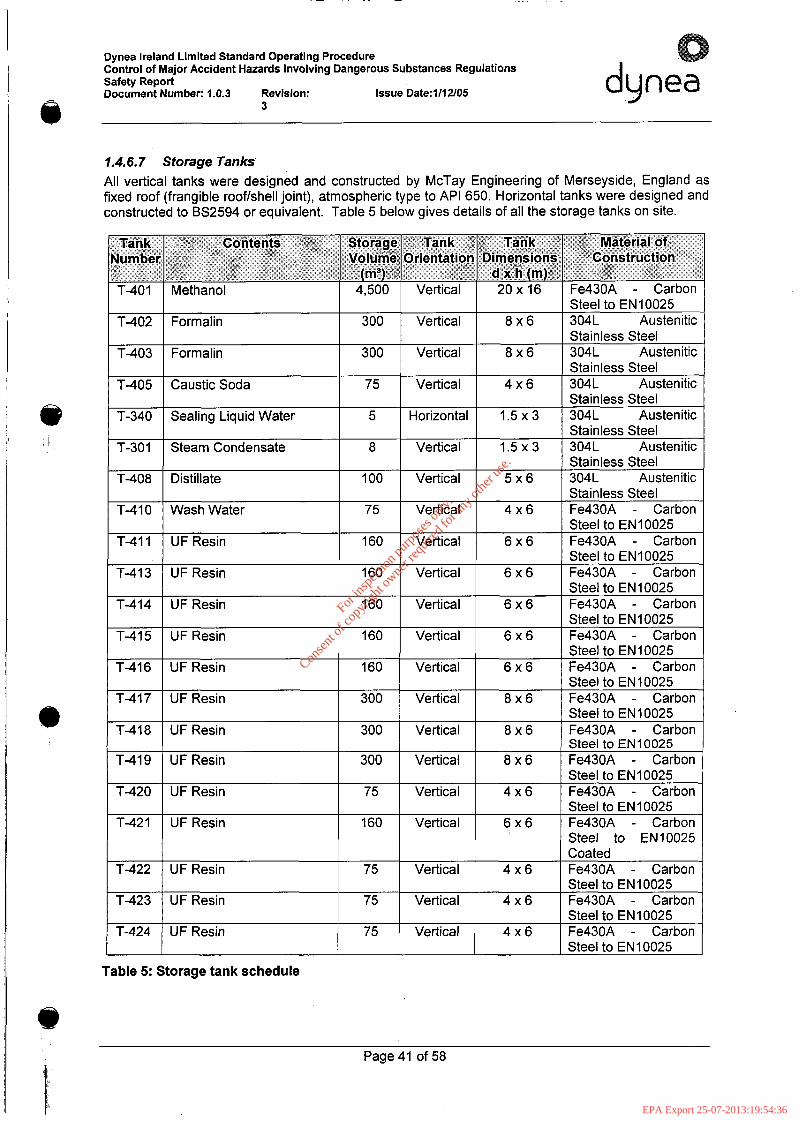
Dynea Ireland Limited Standard Operating Procedure Control of Major Accident Hazards Involving Dangerous Substances Regulations Safety Report Document Number: 1.0.3 Revision: Issue Date:1/12/05 dynea
3 e 1.4.6.7 Storage Tanks All vertical tanks were designed and constructed by McTay Engineering of Merseyside, England as fixed roof (frangible roofkhell joint), atmospheric type to API 650. Horizontal tanks were designed and constructed to BS2594 or equivalent. Table 5 below gives details of all the storage tanks on site.
Tank Contents Storage Tank Tank Material of Jumber Volume Orientation Dimensions Construction
T-401 Methanol 4.500 Vertical 20x 16 Fe430A - Carbon ( m3) d x h (m)
Stainless Steel
Stainless Steel
Steel to EN10025 T-411 UF Resin 160 Vertical 6 x 6 Fe430A - Carbon
I Steel to EN 10025 T-413 I UF Resin I 160 I Vertical I 6 x 6 I Fe430A - Carbon
Steel to EN10025 T-414 UFResin 160 Vertical 6 x 6 Fe430A - Carbon
Steel to EN 10025
Steel to EN10025
Steel to EN10025
T-415 UF Resin 160 Vertical 6 x 6 Fe430A - Carbon
T-416 UFResin 160 Vertical 6 x 6 Fe430A - Carbon
T-417 UFResin 300 Vertical 8 x 6 Fe430A - Carbon Steel to EN 10025
T-418 UFResin 300 Vertical 8 x 6 Fe430A - Carbon Steel to EN10025
T-419 UF Resin 300 Vertical 8 x 6 Fe430A - Carbon Steel to EN10025
T-420 UFResin 75 Vertical 4 x 6 Fe430A - Carbon Steel to EN10025
T-421 UF Resin 160 Vertical 6 x 6 Fe430A - Carbon Steel to EN10025 Coated
T-422 UF Resin 75 Vertical 4 x 6 Fe430A - Carbon I Steel to EN10025
T-423 1 UFResin 75 I Vertical I 4 x 6 1 Fe430A - Carbon Steel to EN10025
T-424 UF Resin 75 Vertical 4 x 6 Fe430A - Carbon I I Steel to EN10025
Table 5: Storage tank schedule
Page 41 of 58
For
insp
ectio
n pur
pose
s only
.
Conse
nt of
copy
right
owne
r req
uired
for a
ny ot
her u
se.
EPA Export 25-07-2013:19:54:36
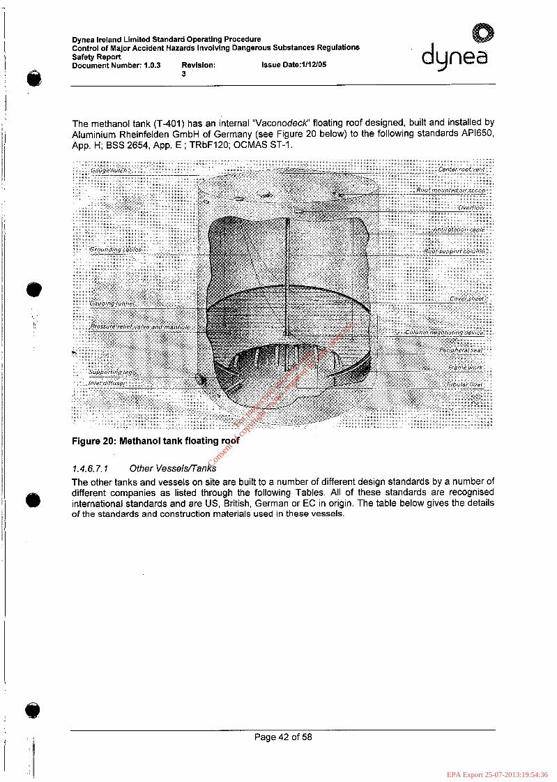
Dynea Ireland Limited Standard Operating Procedure Control of Major Accident Hazards Involving Dangerous Substances Regulations Safety Report Document Number: 1.0.3 Revision: Issue Date:l/l2/05 dynea
i 3
The methanol tank (T-401) has an internal “Vaconodecl? floating roof designed, built and installed by Aluminium Rheinfelden GmbH of Germany (see Figure 20 below) to the following standards AP1650, App. H; BSS 2654, App. E ; TRbF120; OCMAS ST-I.
Figure 20: Methanol tank floating roof
1.4.6.7.7 Other Vesselflanks The other tanks and vessels on site are built to a number of different design standards by a number of different companies as listed through the following Tables. All of these standards are recognised international standards and are US, British, German or EC in origin. The table below gives the details of the standards and construction materials used in these vessels.
Page 42 of 58
For
insp
ectio
n pur
pose
s only
.
Conse
nt of
copy
right
owne
r req
uired
for a
ny ot
her u
se.
EPA Export 25-07-2013:19:54:36
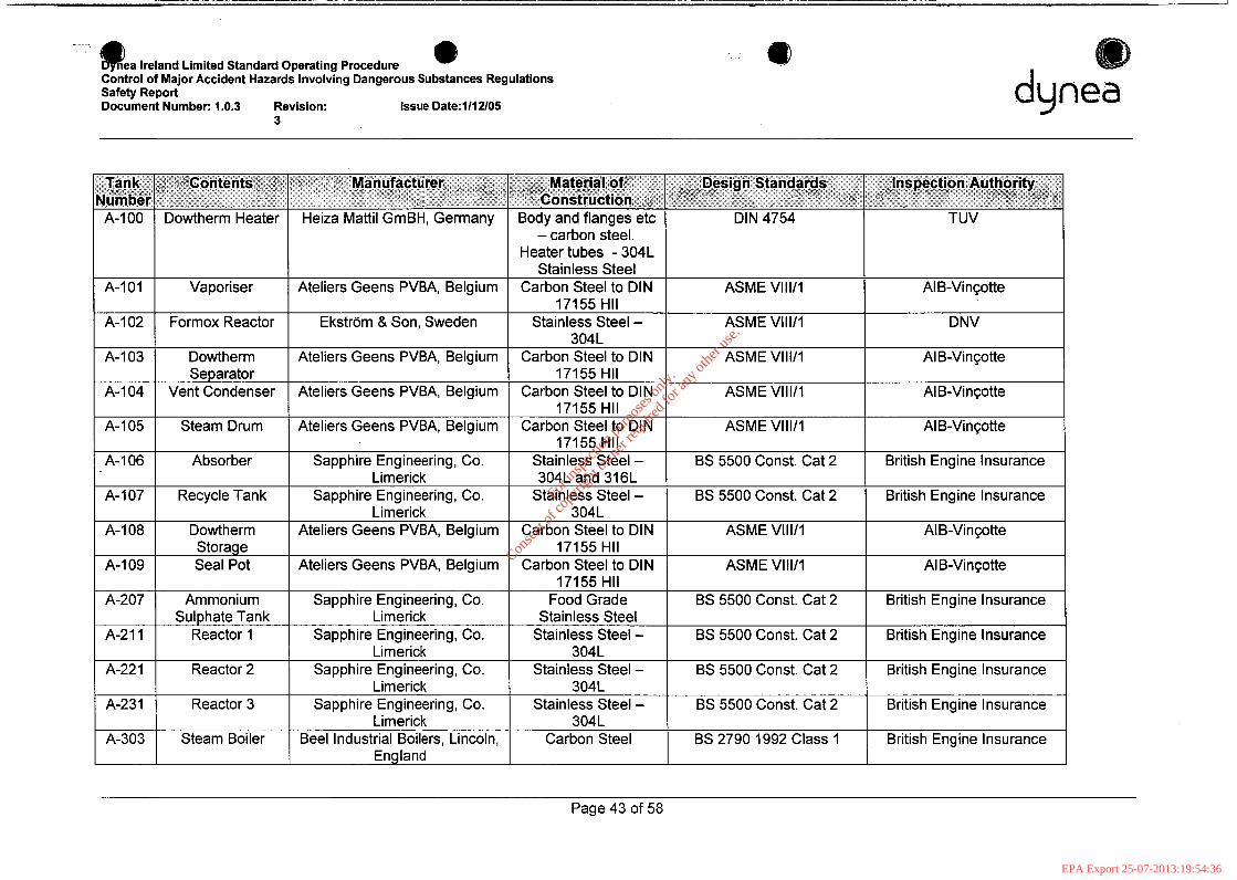
@ea Ireland Limited Standard ODeratina Procedure Q
Ammonium Sulphate Tank
Reactor 1
Reactor 2
Reactor 3
Steam Boiler
Cbntrol of Major Accident Hazards lnvolvhg Dangerous Substances Regulations Safety Report Document Number: 1.0.3 Revision: Issue Date:1/12/05
3
17155 HI1 Sapphire Engineering, Co. Food Grade BS 5500 Const. Cat 2 British Engine Insurance
Sapphire Engineering, Co. Stainless Steel - BS 5500 Const. Cat 2 British Engine Insurance
Sapphire Engineering, Co. Stainless Steel - BS 5500 Const. Cat 2 British Engine Insurance
Sapphire Engineering, Co. Stainless Steel - BS 5500 Const. Cat 2 British Engine Insurance
Beel Industrial Boilers, Lincoln, Carbon Steel BS 2790 1992 Class 1 British Engine Insurance
Limerick Stainless Steel
Limerick 3041
Limerick 3041
Limerick 3041
England
8 duma
J
A-1 01
A-I 02
A-I 03
A-104
A-105
A-I 06
A-I 07
A-I 08
A-I 09
A-207
A-211
A-22 1
A-231
A-303
- carbon steel. I Heatertubes -304L I
Page 43 of 58
For
insp
ectio
n pur
pose
s only
.
Conse
nt of
copy
right
owne
r req
uired
for a
ny ot
her u
se.
EPA Export 25-07-2013:19:54:36

Dynea Ireland Limited Standard ODeratina Procedure
____ Limerick CMBB, Italy
CMBB, Italy
Control of Major Accident Hazards Involvhg Dangerous Substances Regulations Safety Report Document Number: 1.0.3 Revision: Issue Date:l/l2/05
Carbon steel
Carbon steel Galvanised, Coated ASME VIII/I ISPESL
Galvanised, Coated ASME VIII/I ISPESL
5
N/A
Condenser Afte rcoo le r H-102 I
Tank R3 NaOH Dump
H-301 Excess Steam
T-208 Resin production Condenser
area caustic storage tank
T-301 Condensate Tank
1 ;-3: -1 Air Receiver- ~
Air Receiver R I NaOH Dump
Tank I T A - R2 NaOH DumD
Tank
304L
304L Ateliers Geens PVBA, Belgium Stainless Steel - ASME VIII/I AI B-VinGotte
Alcards, Sweden SS 1430, SS 1312 ASME VIII/I SAQ - Swedac Ackreditering
Sapphire Engineering, Co. Carbon steel Not a pressure vessel Manufacturer Limerick
I Carbon steel I I I Table 6: Other tanks and vessels
Page 44 of 58
For
insp
ectio
n pur
pose
s only
.
Conse
nt of
copy
right
owne
r req
uired
for a
ny ot
her u
se.
EPA Export 25-07-2013:19:54:36
Dynea Ireland Limited Standard Operating Procedure Control of Major Accident Hazards Involving Dangerous Substances Regulations Safety Report Document Number: 1.0.3 Revision: Issue
3 Date:lIl2105 dunea
1.4.6.7.2 Bunding The secondary containment measures on site were designed to the standards norms at the time of construction. The standards at the time of construction of the plant required that the capacity of a bund be sufficient to hold 110% of the volume of the largest tank in the bund. This criteria is met. However the standard 11 0% has now been amended to 1 10% of the volume of the largest tank or 25% of the total tank volume in the bund, whichever is greater. This information has come from the IPC guidance note on “Storage and transfer of Materials for scheduled activities” (Ref 01067-22-RP- 001 June 2004).
According to this document there are three types of containment systems
1. Local Bund system around tank 2. Remote 3. Combined A combination of both (1 + 2 above).
A containment system that contains spill away from the source
The tank farm fails the 25% rule as a stand alone local containment system; however there is extra capacity by combining this system and utilising spare capacity of Basin 1 thus meeting the requirement. This will be clarified with Environmental Protection Agency. Dynea commissioned Gannon and Associates to carry out bund integrity testing in 2005. They tested the bunds using the BS 8007standard and the EPA guidelines (Ref 01067-22-RP-001) above. A final report was prepared in August 2005 with actions regarding remedial work on the resin tank farm bund. Dynea have contracted Finbarr Gannon and Associates to carry out this remedial work. Completion of this work will be in the first quarter of 2006.
a. IBC/Chemicals Bund
Width (Internal) (W) = 8.07m Length (internal) (L) = 17.14m Minimum Height (at ramp) (H min) = 0.09m Maximum Height (at wall) (H max) = 0.17m
Volume of the bund = W x L x H min =
8.07m x 17.14m x 0.09m = 12.45m3
If the ramp was increased in height to the height of the bund wall then the volume would increase to 23.5m3.
No more than 10m3 of material will be stored in the bund so 110% of 10 = 11 m3. Largest tank in the bund will be ImS.
This bund, therefore meets the current best practice criteria for capacity.
b. Diesel Tank Bund
Width (Internal) (W) = 2.9m Length (internal) (L) = 2.6m Minimum Height (H min) = 0.56m
Volume of bund = 2.9m x 2.6m x 0.56m = 4.22m3
Tank volume = 1 .3m3 so the bund easily meets the 11 0% and 25% rules.
C. Methanol Tank Bund
Page 45 of 58
For
insp
ectio
n pur
pose
s only
.
Conse
nt of
copy
right
owne
r req
uired
for a
ny ot
her u
se.
EPA Export 25-07-2013:19:54:36
Dynea Ireland Limited Standard Operating Procedure Control of Major Accident Hazards Involving Dangerous Substances Regulations Safety Report Document Number: 1.0.3 Revision: Issue
3 Date:1112/05
The methanol tank bund has a capacity of 5,500m3. The methanol tank (T401) itself has a capacity of 4,500m3 so 110% of 4,500m3 = 4,950m3. Given that the bund only contains one tank, the 25% rule doesn’t apply.
d. Methanol Tanker Loading Area Bund
The actual volume of the methanol tanker loading area bund is difficult to calculate exactly due to sloping in certain parts of the bund. The figures below, therefore, give the minimum volume (the sloping is downward and will increase the bund volume).
Wall height = 0.21 m Bund length = 17.83m Bund width = 7.83m
Volume = 0.21 x 17.83 x 7.83 = 29.32m3
Roof support plinths, tanker buffers and other units in the bund will reduce this volume by approximately 0.95m3 so the actual minimum volume (see note above) of the bund is 28.37m3. Any spillage into the bund is automatically pumped, by air activated pump, into the methanol tank bund. The maximum tanker load which will be filled in this bund is 32.5m3. While the bund volume does not appear to meet the 110% criteria for tank capacity (note that the bund volume will actually be more than that given), the fact that material will be pumped into the larger bund obviously means that the capacity of the larger bund can also be taken into account.
e. Tank Farm Bund
This bund meets the 110% of largest tank volume specification which would have been the standard at time of construction. It would not, however, meet the 25% of total tankage specification.
f SpigoVJe tting Flow According to EPA Guidance Note on Storage and Transfer of Materials for Scheduled Activities spigot or jetting flow is defined as:
”a failure at the side of a tank, e.g. through a rupture or corrosion of the side wall, could result in the escape of a jet of liquid with sufficient force that it projects over the bund wall”.
It states that perimeter around the tank (p) must have a width of at least half the height (h) by which the tank protrudes above the bund wall.
i. IBC Bund
Height of IBC = 1.2m Height of 2001 drum on pallet = 1.03m
Height of bund wall = 0.17m
There the height by which an IBC protrudes over the bund wall (h) = 1.2 - 0.17 = 1.03m
The perimeter around the tank must at least equal half of this value so p 3 h/2
h/2 = 0.52m so IBCs must be placed at least 0.52m away from the bund wall to meet the criteria
2001 drums on pallets must be placed at least (1.03 - 0.17)/2m = 0.43m away from the bund wall.
Page 46 of 58
For
insp
ectio
n pur
pose
s only
.
Conse
nt of
copy
right
owne
r req
uired
for a
ny ot
her u
se.
EPA Export 25-07-2013:19:54:36
Dynea Ireland Limited Standard Operating Procedure Control of Major Accident Hazards involving Dangerous Substances Regulations Safety Report Document Number: 1.0.3 Revision: Issue
3 Date:l/l2105
I
ii. Diesel Tank Bund
Height of tank = 2.35m Height of bund wall = 0.56m
h = 2.35 - 0.56 = 1.79m h/2 = 0.895m
The minimum p of this tank is 0.74m (max is 0.86m). Therefore the tank bund does not meet these criteria. It should be said that the risk from a spill here is minimal as the drain is positioned a good distance away from the bund wall. This deficiency in the bund design will be noted and either the tank lowered on its stand or the height of the wall increased.
Methanol Tank Bund ... 111.
Tank height = 16m Bund wall height = 2.95m
h = 16m - 2.95m = 13.05m h/2 = 6.525m
The minimum perimeter (p) between the bund and tank walls = 9.95m so the bund meets the criteria.
iv. Methanol Tanker Loading Area Bund
The tallest road tanker which would use the loading bay has a height of 3.7m
The bund wall = 0.2m tall
Therefore, h = 3.5m
The minimum perimeter (p) between the tanker and the bund wall = 1.8m so as p 2 h/2 the necessary criteria are met. The loading bay on this side is covered by the canopy wall which reaches down to a point at or below the level of the bottom of the tanker barrel so extra protection is available here. The perimeter on the other side is 3.7m. At the front the perimeter is a minimum of 2.5m and at the back is a minimum of 4.5m so all is well within spec here.
V. Tank Farm Bund
This bund is not designed for prevention of either overtopping (due to catastrophic tank failure) or jetting/spigot flow as there is a low bund wall relative to the tank height and the tanks are positioned relatively close to the wall.
Any spillage from the tank farm bund will be onto the roadway and will be contained within the drain system so no threat to the aquatic or terrestrial environment would result.
I
Page 47 of 58 I ,
For
insp
ectio
n pur
pose
s only
.
Conse
nt of
copy
right
owne
r req
uired
for a
ny ot
her u
se.
EPA Export 25-07-2013:19:54:36
Dynea Ireland Limited Standard Operating Procedure Control of Major Accident Hazards Involving Dangerous Substances Regulations Safety Report Document Number: 1.0.3 Revision: Issue dynea
II 3 Date:l/l2/05 a
1.4.6.8 Plant Utilities
1.4.6.8.1 Electricity Dynea’s site is supplied by one feeder cable from the IF1 (in liquidation) main sub station to our main incoming 6.3 kV switchboard. Our maximum demand usage is approximately 1.1 MW. There are 3 No. 6.3 kV to 400 volt transformers located site wide 1 at MCCl 1.6 MVA, 1 at MCC2 630 kVA and 1 at MCC3 3 MVA. It is at each of these MCC’s that the voltage is distributed for use on motors pumps drives etc.
There is a main fire man’s switch which shuts off the 6.3 kV supply to the 3 No site transformers located up above the door at the 6.3 kV switch room. This is indicated on the site plan drawing. The high tension cables run underground and are protected from damage due to excavation etc by wooden sleepers running over the cables. A diagram showing the where the high tension cable runs in the plant is given in (Figure 21) @
/ /
Page 48 of 58
For
insp
ectio
n pur
pose
s only
.
Conse
nt of
copy
right
owne
r req
uired
for a
ny ot
her u
se.
EPA Export 25-07-2013:19:54:36
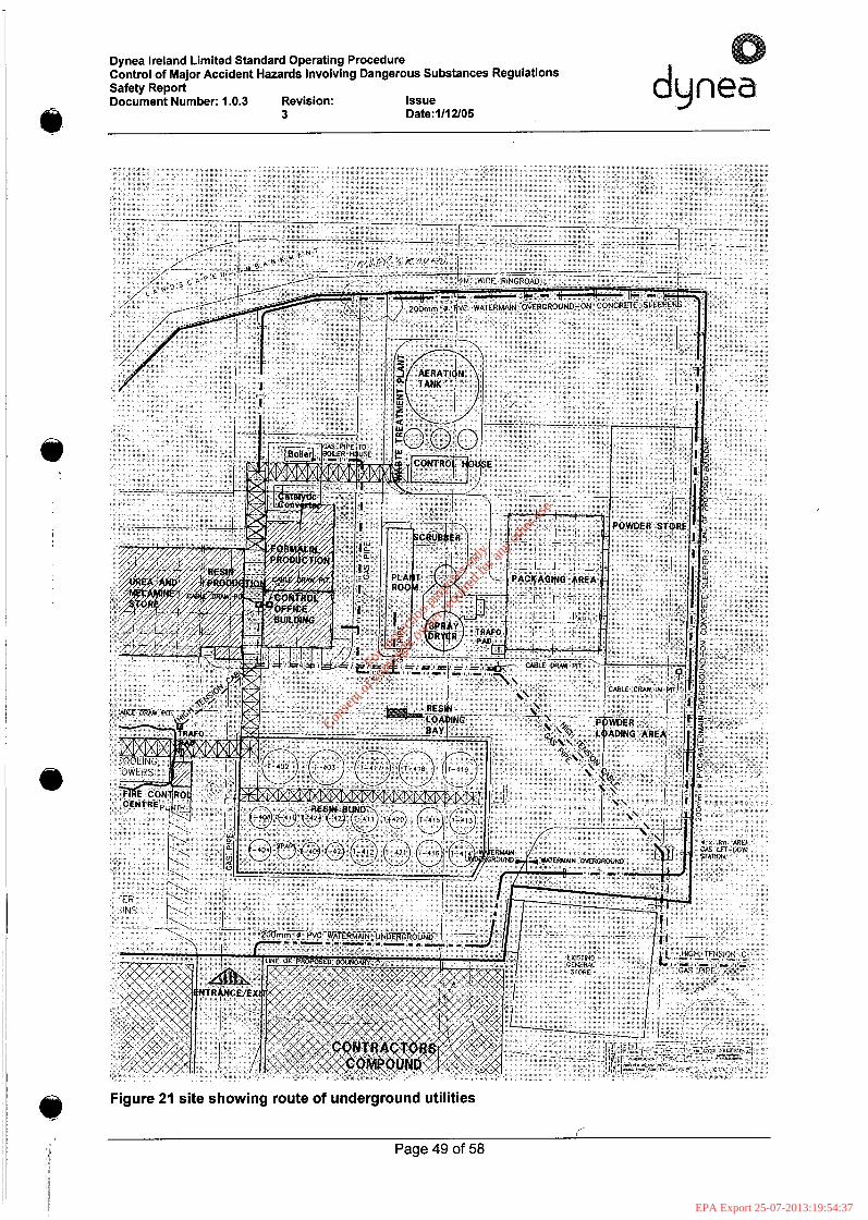
Dynea Ireland Limited Standard Operating Procedure Control of Major Accident Hazards Involving Dangerous Substances Regulations Safety Report Document Number: 1.0.3 Revision: Issue dynea
3 Date:l/l2/05
Figure 21 site showing route of underground utilities Q r
Page 49 of 58 <!
For
insp
ectio
n pur
pose
s only
.
Conse
nt of
copy
right
owne
r req
uired
for a
ny ot
her u
se.
EPA Export 25-07-2013:19:54:37
Dynea Ireland Limited Standard Operating Procedure Control of Major Accident Hazards Involving Dangerous Substances Regulations Safety Report Document Number: 1.0.3 Revision: Issue dynea
3 Date:1/12/05 @
There is a UPS (Uninterruptible Power Supply) back up supplying the Uniprocess DCS and has approximately 1 hour back up in the event of a power failure. In the event of a power failure at the site the following plant facilities would be affected:
0 Formoxarea 0 Resin Reactors 0 Plant Utilities
In the event of a power failure the formox process will shutdown in the safe mode. This process has occurred in the past and the plant behaved as was expected. The most critical part of batch production is during condensation. In the event of a power failure emergency caustic is available to "kill" the condensation reaction. Agitation of the batch is provided by a diesel compressor that is left on standby by the reactor floor which provides air to the base of the reactor and agitates the liquid. Other steps of the batch process are not affected critically by loss of power.
Plant utilities will also be affected by loss of power. Methanol loading will cease once the power has failed and all valves will close in the safe position. Methanol loading at the Jetty will also cease once power between Dynea and IF1 (in liquidation) is no longer available. An alarm is sounded on the jetty and all pumps are stopped and valves are automatically closed. Pumps on the ship will be switched off. Other utilities around the site will not have a serious consequence once power is lost.
0 i j
1.4.6.8.2 Gas The gas pipe enters the Dynea site on the south eastern side of the plant from the IF1 (in liquidation) site. The gas passes a reducing substation and then into the plant for usage. Consumption of gas has reduced considerably since the closure of the powder plant. The gas line is spaded off at the point of entry at the powder plant. In the year 2003, Dynea used 33,128 m3 of gas only. Gas is used specifically for running the boiler when steam is not available from the Dowtherm condenser to service reactors. The main risk associated with the gas line would be due to a rupture in the pipe itself or if a problem arose at the boiler house. The gas pipe is made from plastic and is built to a recognised standard. The route of the line is given in (Figure 21 site showing route of underground utilities).
I. 4.6.8.3 Instrument Air Supply All Dynea's instrumentation and utilities are fed from a common compressed air supply. This is supplied by 3 No air compressors 1 No Kaser 1 1 0 k W compressor 1 No. Compair 95 k W compressor and 1 No 70 kW compare compressor. The air is stored in two air receivers 1 m3 each at 6.5 bar approximately.
e
The air is then fed through two air dryers 1 No set of Dominic Hunter dryers or 1 No Ultra Filter and from there the air is fed around to the end users. If the air is lost for whatever reason all pneumatic valves will shut down in the safe mode. This will have the effect of shutting down the methanol valves to the formox. High level oxygen alarms will also be triggered on Uni-process. This is a safe condition as the molar ratio is zero between oxygen and methanol.
Valves on the reactors will also shut. If this occurs during condensation caustic will not be added in the conventional manner. In this scenario emergency caustic is added manually to the batch and the reaction stopped and full cooling will be put on.
The valves in the methanol loading will also shut. This means that methanol cannot be loaded until compressed air is restored. On the jetty there is an independent compressor which supplies air to the actuated valves. If this fails the valves on the jetty will shutdown safely.
Q Page 50 of 58
For
insp
ectio
n pur
pose
s only
.
Conse
nt of
copy
right
owne
r req
uired
for a
ny ot
her u
se.
EPA Export 25-07-2013:19:54:37
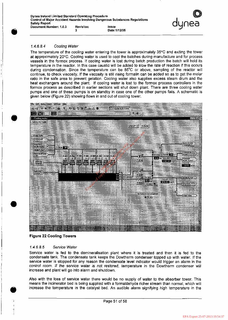
Dynea Ireland Limited Standard Operating Procedure Control of Major Accident Hazards Involving Dangerous Substances Regulations Safety Report Document Number: 1.0.3 Revision: Issue
3 Date:l/l2/05
I
duglea
I . 4.6.8.4 Cooling Water The temperature of the cooling water entering the tower is approximately 35°C and exiting the tower at approximately 20°C. Cooling water is used to cool the batches during manufacture and for process vessels in the formox process. If cooling water is lost during batch production the batch will hold its temperature in the reactor. In this case caustic will be added to slow the rate of reaction if this occurs during condensation. Since the temperature can be 85OC or above, sampling of the reactor will continue, to check viscosity. If the viscosity is still rising formalin can be added so as to get the molar ratio in the safe area to prevent gelation. Cooling water also supplies excess steam drum and the heat exchangers around the plant. If cooling water is lost to the formox process controllers in the formox process as described in earlier sections will shut down plant. There are three cooling water pumps and one of these pumps is on standby in case one of the other pumps fails. A schematic is given below (Figure 22) showing flows in and out of cooling tower.
Figure 22 Cooling Towers
1.4.6.8.5 Service Water Service water is fed to the demineralisation plant where it is treated and then it is fed to the condensate tank. The condensate tank keeps the Dowtherm condenser topped up with water. If the service water is stopped for any reason the condensate level indicator would trigger an alarm in the control room. If the service water is not restored, temperature in the Dowtherm condenser will increase and plant will go into alarm and shutdown.
Also with the loss of service water there would be no supply of water to the absorber tower. This means the incinerator bed is being supplied with a formaldehyde richer stream than normal, which will increase the temperature in the catalyst bed. An audible alarm signifying high temperature in the
Page 51 of 58
For
insp
ectio
n pur
pose
s only
.
Conse
nt of
copy
right
owne
r req
uired
for a
ny ot
her u
se.
EPA Export 25-07-2013:19:54:37
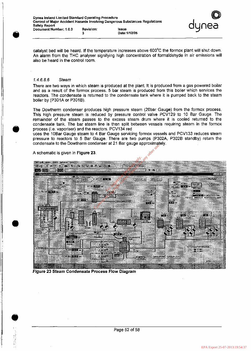
Dynea Ireland Limited Standard Operating Procedure Control of Major Accident Hazards Involving Dangerous Substances Regulations Safety Report Document Number: 1.0.3 Revision: Issue
3 Date:IIl U05
I
dunea
catalyst bed will be heard. If the temperature increases above 6OO0C the formox plant will shut down. An alarm from the THC analyser signifying high concentration of formaldehyde in air emissions will also be heard in the control room.
1.4.6.8.6 Sfeam There are two ways in which steam is produced at the plant. It is produced from a gas powered boiler and as a result of the formox process. 5 bar steam is produced from this boiler which services the reactors. The condensate is returned to the condensate tank where it is pumped back to the steam boiler by (P301A or P301B).
The Dowtherm condenser produces high pressure steam (20bar Gauge) from the formox process. This high pressure steam is reduced by pressure control valve PCV129 to 10 Bar Gauge. The remainder of the steam passes to the excess steam drum where it is cooled returned to the condensate tank. The bar steam line is then split between vessels requiring steam in the formox process (i.e. vaporiser) and the reactors. PCVl34 red uces the 10Bar Gauge steam to 4 Bar Gauge servicing formox vessels and PCVl33 reduces steam pressure to reactors to 5 Bar Gauge. There are two pumps (P302A, P302B standby) return the condensate to the Dowtherm condenser at 21 Bar gauge approximately.
A schematic is given in Figure 23.
Page 52 of 58
For
insp
ectio
n pur
pose
s only
.
Conse
nt of
copy
right
owne
r req
uired
for a
ny ot
her u
se.
EPA Export 25-07-2013:19:54:37
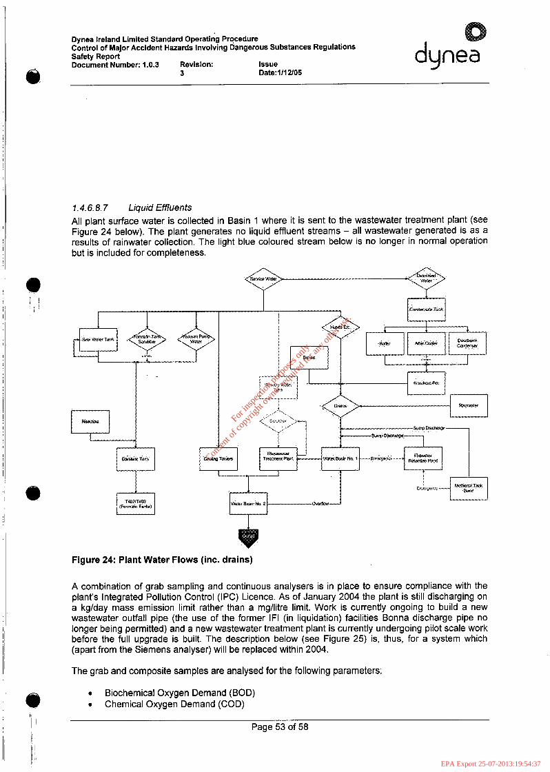
Dynea Ireland Limited Standard Operating Procedure Control of Major Accident Hazards Involving Dangerous Substances Regulations Safety Report Document Number: 1.0.3 Revision: Issue dynea
3 Date:1/12105
1.4.6.8.7 Liquid Effluents All plant surface water is collected in Basin 1 where it is sent to the wastewater treatment plant (see Figure 24 below). The plant generates no liquid effluent streams - all wastewater generated is as a results of rainwater collection. The light blue coloured stream below is no longer in normal operation but is included for completeness.
1 I
I _I
Figure 24: Plant Water Flows (inc. drains)
A combination of grab sampling and continuous analysers is in place to ensure compliance with the plant's Integrated Pollution Control (IPC) Licence. As of January 2004 the plant is still discharging on a kglday mass emission limit rather than a mg/litre limit. Work is currently ongoing to build a new wastewater outfall pipe (the use of the former IF1 (in liquidation) facilities Bonna discharge pipe no longer being permitted) and a new wastewater treatment plant is currently undergoing pilot scale work before the full upgrade is built. The description below (see Figure 25) is, thus, for a system which (apart from the Siemens analyser) will be replaced within 2004.
The grab and composite samples are analysed for the following parameters:
0 Biochemical Oxygen Demand (BOD) CD 0 Chemical Oxygen Demand (COD) I1
I ! Page 53 of 58 /i
For
insp
ectio
n pur
pose
s only
.
Conse
nt of
copy
right
owne
r req
uired
for a
ny ot
her u
se.
EPA Export 25-07-2013:19:54:37
Dynea Ireland Limited Standard Operating Procedure Control of Major Accident Hazards Involving Dangerous Substances Regulations Safety Report Document Number: 1.0.3 Revision: Issue
3 Date:l/l2/05
I
duma J
Total Suspended Solids (TSS) Total Nitrogen Formaldehyde Ammonia PH Phosphorous Oils, Fats and Grease
Based on the analysis of the final effluent tank grab sample (no inputs from the buffer tanks take place either during this analysis or while material is being pumped to Basin No. 2) the laboratory personnel calculate the permissible discharge volume. This information is then passed onto the shift leader who inputs the volume into the plant control system which then shuts off the pumps once this set point is reached.
The continuous analyser is a Siemens Aquascan system designed for the analysis of liquid effluents from a plant. The unit analyses the following parameters:
Biochemical Oxygen Demand (BOD) Chemical Oxygen Demand (COD) Total Organic Carbon (TOC) Total Suspended Solids (TSS) Ammonia
Conductivity Turbidity Colour Sample Temperature
PH
The ammonia and pH results are outputted to the plant control system. If the pH reading should come within 0.4 pH units of the limits then the pump will be automatically shut off. The working range for discharge from the wastewater treatment plant is thus 6.4 - 8.6 pH units. The ammonia reading works in conjunction with the flow meter to give a kg of ammonia discharged. The pump will cut off once the preset limit (which is 10% less than the licence limit) is reached. This system is a backup to ensure that licence limits will not be breached should an undetected or unreported spill occur on site.
The tanks in the wastewater treatment plant are all above ground riveted coated steel tanks except for T608 which is a concrete tank. Water Basin 2 is located separately to the wastewater treatment plant but is of the same construction as the tanks in that area.
Page 54 of 58
For
insp
ectio
n pur
pose
s only
.
Conse
nt of
copy
right
owne
r req
uired
for a
ny ot
her u
se.
EPA Export 25-07-2013:19:54:37
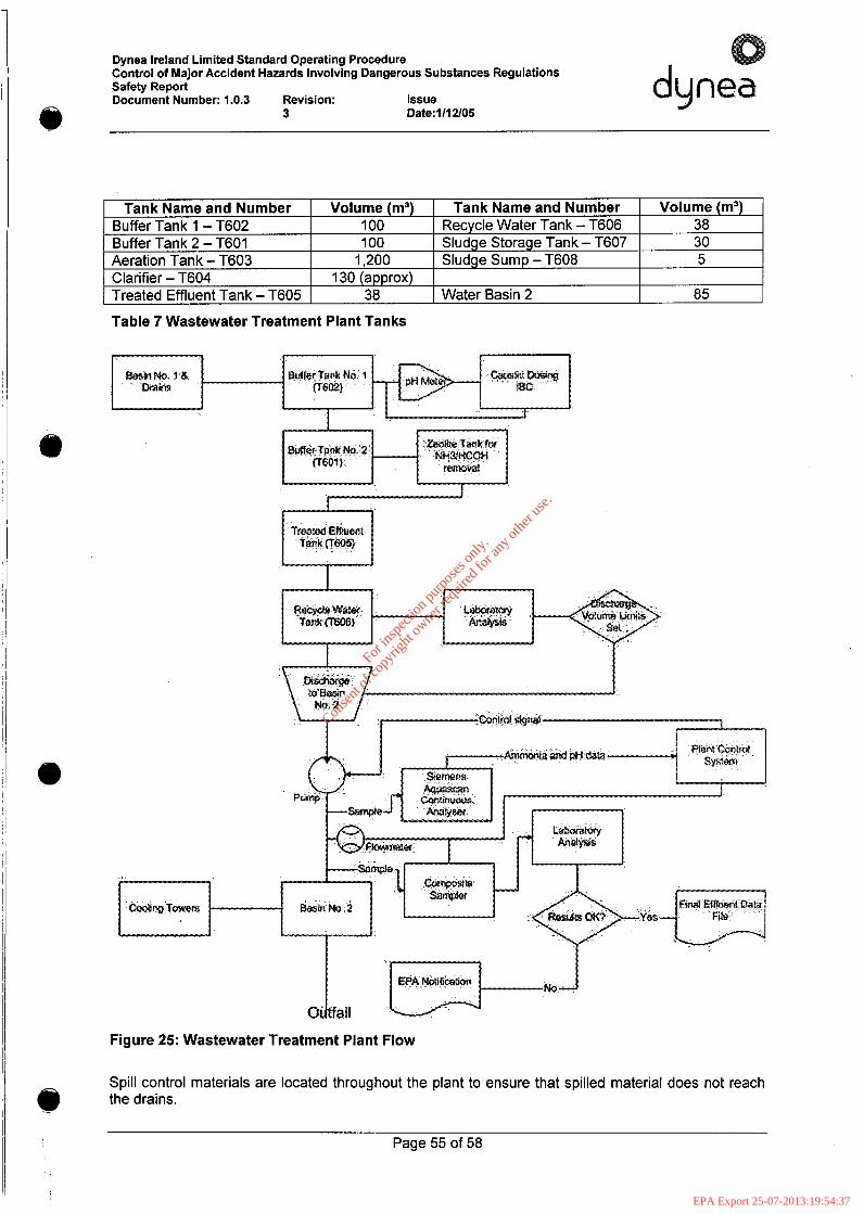
I
Q
Tank Name and Number Volume (m3) Tank Name and Number 100 Recycle Water Tank - T606 100 Sludge Storage Tank - T607
Buffer Tank 1 - T602 Buffer Tank 2 - T601 Aeration Tank - T603 1,200 Sludge Sump - T608 Clarifier - T604 130 (approx) Treated Effluent Tank - T605 38 Water Basin 2
l
l
I
i I
a
Volume (m3) 38 30 5
85
Dynea Ireland Limited Standard Operating Procedure Control of Major Accident Hazards Involving Dangerous Substances Regulations Safety Report Document Number: 1.0.3 Revision: Issue
3 Date:lll2/05
I
duma
Table 7 Wastewater Treatment Plant Tanks
. i
A I
Figure 25: Wastewater Treatment Plant Flow
Spill control materials are located throughout the plant to ensure that spilled material does not reach the drains.
Page 55 of 58
For
insp
ectio
n pur
pose
s only
.
Conse
nt of
copy
right
owne
r req
uired
for a
ny ot
her u
se.
EPA Export 25-07-2013:19:54:37
Dynea Ireland Limited Standard Operating Procedure Control of Major Accident Hazards Involving Dangerous Substances Regulations Safety Report Document Number: 1.0.3 Revision: Issue dynea
3 Date:l/l2/05
Typical stocks of spill control materials would be: 12 Tonnes “dead” sand 2 Tonnes “Adzorb multi-purpose absorbent 250kg “Green Stuff absorbent 20 x 1.5 metre chemical absorbent booms 20 x 1.5 metre hydrophobic booms (for oil spills and for use on the jetty during urea ship offloading) 200 x 400mm2 absorbent pads.
Pumping of effluent to outfall from the Dynea Ireland site occurs only as a result of manual intervention - there is no provision for automatic pump outs from the system.
Page 56 of 58
For
insp
ectio
n pur
pose
s only
.
Conse
nt of
copy
right
owne
r req
uired
for a
ny ot
her u
se.
EPA Export 25-07-2013:19:54:37
Dynea Ireland Limited Standard Operating Procedure Control of Major Accident Hazards Involving Dangerous Substances Regulations Safety Report Document Number: 1.0.3 Revision: Issue Date:
Page 57 of 58
For
insp
ectio
n pur
pose
s only
.
Conse
nt of
copy
right
owne
r req
uired
for a
ny ot
her u
se.
EPA Export 25-07-2013:19:54:37


