Attack Angle and Strength of Rudders for Power-free Underwater Vehicle in Kuroshio
Chuan-Tsung Lee1, Huang Hsing Pan 1, Ray-Yeng Yang2, Pei-ChiChang2 and Po-Chang Lee1 1Department of Civil Engineering, Kaohsiung University of Applied Sciences, Kaohsiung, TAIWAN, China
2 Tainan Hydraulics Laboratory, Cheng Kung University, Tainan, TAIWAN, China
ABSTRACT Power-free underwater vehicle with two rudders is developed and works in Kuroshio. Applied loads and strength of the rudder are determined by CFD and ANSYS at 0.3~1.8 m/s. A tested vehicle was conducted at 0.65 m/s flow in harbor. We concentrate on attack angle and strength of rudders of power-free underwater vehicle in low flow velocity. Results indicate that only 73.7% effective downward pressure of the rudder was measured due to the influence of turbulent flow. Pitch angle applied to the vehicle is essential to assure definitely submersible. Front rudder and rear rudder had better not be aligned in order to reduce the effect of wake flow. At flow velocity of 1.8 m/s, maximum lift force and drag force on the rudder are -13.0 kN and 8.05 kN, respectively. Maximum displacements locate on both end of rudder with a value of 0.673 mm. Deformation ratio of the rudder is 1/3165. Numerical calculations and the experiments reveal the rudder of power-free underwater vehicle is elastic. KEY WORDS: Rudder; power-free; underwater; Kuroshio; electricity. INTRODUCTION Due to excessive use of fossil fuels causing the environmental problems, an exploration of clean and renewable energy is essential all over the world nowadays. Ocean currents with stable flow speed and direction have an advantage over the other clean energies for electric power. Kuroshio is one of ocean currents in the Pacific passing through the eastern Taiwan, with a band of 120~170 km and flow speed of 1.0~1.5 m/s (Andres, 2008; Johns, 2011). According to monsoons and seasonal variation influence, the total power reaches 4 GW in winter and 10 GW in summer near the eastern Taiwan, and has an average of 5.5 GW for several representative cross sections (Hsin, 2008). Kuroshio’s flow velocity is pretty stable heading the north or northeast, and its flow capacity is about 20.7~22.1 Sv (Chen, 2010). Estimated reserves of Kuroshio power near Taiwan are at least 30 GW (Hsu, 1999; Tang, 2010). Kuroshio power potentially provides clean ocean energy for electricity. In operation, a floating vehicle carrying dynamo is necessary for
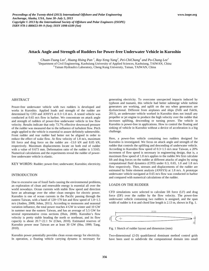
generating electricity. To overcome unexpected impacts induced by typhoon and tsunami, this vehicle had better submerge while turbine generators are working, and uplift on the sea when generators are dysfunctional. Different from airplanes and ships (Felli and Falchi, 2011), an underwater vehicle worked in Kuroshio does not install any propeller or jet engine to produce the high velocity over the rudder that increases uplifting, descending or turning power. The vehicle in Kuroshio is power-free in applications. How to control the floating and sinking of vehicle in Kuroshio without a device of acceleration is a big challenge. Here, a power-free vehicle containing two rudders designed for Kuroshio is investigated. We focus on attack angle and strength of the rudder that controls the uplifting and descending of underwater vehicle. According to Kuroshio flow speed of 0.3~1.5 m/s near Taiwan, a 20% increment of flow speed is necessary in engineering design, that is, a maximum flow speed of 1.8 m/s applies to the rudder.We first calculate lift and drag forces on the rudder at different attacks of angles by using computational fluid dynamics (CFD) under 0.3, 0.65, 1.0 and 1.8 m/s flow respectively. Then, stresses and displacements of the rudder are estimated by finite element analysis (ANSYS) at 1.8 m/s. A prototype underwater vehicle navigated at 0.65 m/s flow was conducted in harbor and compared with numerical calculations of the rudder. LOADS ON THE RUDDER CFD simulations were selected to calculate lift force (LF) and drag force (DF) over the rudder by the flow velocity. The power-free underwater vehicle containing two rudders is assigned, and the span width of rudder is 4 m and chord line length is 2.13 m, shown in Fig. 1.
Fig. 1 Sketch of rudder layout and dimension (mm) Two-dimensional (2-D) quadrilateral dominant method control grids have been used to subdivide the computational domain into small
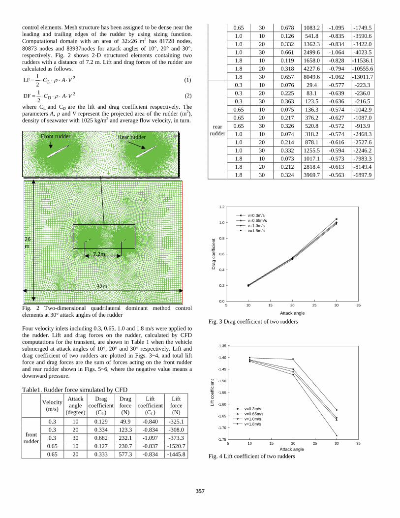
control elements. Mesh structure has been assigned to be dense near the leading and trailing edges of the rudder by using sizing function. Computational domain with an area of 32×26 m2 has 81728 nodes, 80873 nodes and 83937nodes for attack angles of 10°, 20° and 30°, respectively. Fig. 2 shows 2-D structured elements containing two rudders with a distance of 7.2 m. Lift and drag forces of the rudder are calculated as follows.
221LF VACL ⋅⋅⋅⋅= ρ (1)
2D2
1DF VAC ⋅⋅⋅⋅= ρ
(2)
where CL and CD are the lift and drag coefficient respectively. The parameters A, ρ and V represent the projected area of the rudder (m2), density of seawater with 1025 kg/m3 and average flow velocity, in turn.
Fig. 2 Two-dimensional quadrilateral dominant method control elements at 30° attack angles of the rudder Four velocity inlets including 0.3, 0.65, 1.0 and 1.8 m/s were applied to the rudder. Lift and drag forces on the rudder, calculated by CFD computations for the transient, are shown in Table 1 when the vehicle submerged at attack angles of 10°, 20° and 30° respectively. Lift and drag coefficient of two rudders are plotted in Figs. 3~4, and total lift force and drag forces are the sum of forces acting on the front rudder and rear rudder shown in Figs. 5~6, where the negative value means a downward pressure. Table1. Rudder force simulated by CFD
Fig. 6 Lift forces of two rudders Fig. 3 indicates the drag coefficients of rudder increase with increasing attack angles, and will reduce as the flow velocity raise from 0.3 to 1.8 m/s. At 0.65 m/s shown in Table 1, for example, CD of the front rudder is 0.127, 0.333 and 0.678 for attack angles of 10°, 20° and 30°, respectively. Drag coefficients of rear rudder has the similar trend. CD at the front rudder is almost twice of the rear rudder. Attack angle of the rudder is a dominate factor to affect the drag coefficient. From Fig. 3, flow velocity is less effective to CD of the underwater vehicle. In Table 1, the lift coefficient first decreases and then increases as attack angles increase from 10° to 30° for both front and rear rudder. However, total (the sum of front and rear rudder) CL increases as the attack angle raises, shown in Fig. 4. Besides, the value of CL at 0.3 m/s is higher than that at 1.8 m/s for any attack angles. When CL and CD were found, we continue to evaluate lift and drag forces of the underwater vehicle by using Eq. (1) and (2), and results are also shown in Table 1. Total LF and DF strongly depend on flow velocity, plotted in Figs. 5 and 6. In Fig. 5, drag forces at 10°, 20° and 30° attack angles, respectively, are 2.67 kN, 7.05 kN and 12.02 kN if flow velocity is 1.8 m/s. The drag force increases tremendously with increasing attack angles of the rudder. When a series of underwater vehicles are hold by the cables during the operation in Kuroshio, we
should pay attention to total drag forces change as the attack of angle alters in operations. In Table 1, the maximum lift force occurs at 1.8m/s and 30° attack angles with the value of -13.0 kN and -6.9 kN approximately on the front rudder and rear rudder, respectively. Apparently, lift force on the rear rudder is less than that on the front one because of the action of turbulent flow. Figs. 7 and 8 display the contour of total pressure and flow velocity, respectively, at the velocity inlets of 1.8 m/s and attack angles of 30°, where the distance between two rudders is 7.2 m. Turbulent flow is tail water caused by the front rudder that affects lift forces of the rear rudder. Turbulence effect to the rear rudder becomes important as attack angles of the rudder gradually increase shown in Table 1. From Fig. 6, flow velocity is more important than the attack angle for lift force of the underwater vehicle, where the sum of LF is -19.9 kN at 1.8 m/s and 30° attack angles.
Fig. 7 Contour of total pressure at 1.8m/s inlets and 30° attack angles
Fig. 8 Contour of flow velocity at 1.8m/s inlets and 30° attack angles
358
MECHANICAL PROPERTIES OF THE RUDDER From Table 1, a maximum lift force of 13.01 kN and maximum drag force of 8.05 kN are found, respectively, at 1.8 m/s and 30° attack angles. We select these two loadings applied to the rudder, and then calculate the strength of the rudder by ANSYS. Three dimensional (3-D) automatic control grids have been used to subdivide the rudder (computational domain) into small control elements. The relevance valve is 100, sizing relevance center setting “Fine”, and sizing smoothing is “High”. Fig. 9 shows 3-D structured elements in the rudder with the span width of 4 m and chord line length of 2.13 m, where mesh structure contains 210949 nodes and 106983 elements. The material of rudder is steel with the density of 7.85e-6 kg/mm3, tensile yield strength of 250 MPa and tensile ultimate strength of 460 MPa. There are three supports (two cylindrical supports and one fixed support) on the rudder in calculations, shown in Fig. 9.
Fig. 9 Three-dimensional structured elements of the rudder with three supports Lift force of -13011.7 N and the drag force of 8049.6 N were applied to the rudder, shown in Fig. 10. We defined the lift force acting on the +Y direction and drag force on the +X direction.
Fig. 10 Lift force and drag force acting on the rudder Results for equivalent (von Mises) stresses of the rudder are shown in Fig. 11. The maximum equivalent stress is 25.17 MPa, only 10% of tensile yield strength. Fig. 12 is the results for maximum principal stresses of the rudder. The maximum value of maximum principal
stress is 32.29 MPa, and that is 12.9% tensile yield strength of the material. Therefore, the rudder is still in elastic region under 1.8 m/s velocity inlets and 30° attack angles condition.
Fig. 11 Equivalent stress of the rudder
Fig. 12 Maximum principal stress of the rudder Total displacements of the rudder are computed and shown in Fig. 13. Maximum displacements located on both end of rudder are found with 0.673 mm. Compared with the chord line length of 2130 mm, the deformation ratio of the rudder is 1/3165 which is less the allowable deformation of 1/800.
Fig. 13 Total deformation of the rudder
359
EXPERIMENTS OF UNDERWATER VEHICLE Underwater vehicle does not install any propellers or engine, and the only designed power comes from ocean current of Kuroshio. This power-free tested vehicle needs to navigate under water when dynamos work, and uplift when dynamos fail. To assure the designed power-free underwater vehicle suitable for working in Kuroshio, a prototype vehicle with 12 m in length and 4.5 m in width is made by Wanchi Steel Industry Co., Ltd. (Taiwan), shown in Fig. 14. Two rudders made by ASTM A-36 steel are aligned individually on the front side and back side of the vehicle with a distance of 7.2 m in between. The dimension of the rudder is the same as Fig. 1. The vehicle weight is 38.9 kN. To maintain the vehicle buoyant on water before submerged, three PVC-pipe rafts on the left and right sides provide the buoyancy source of the vehicle. Let the reserved buoyancy force for the tested vehicle be 1.96 kN in advance. In Fig. 14, two hydraulic cylinders are installed to adjust attack angles of rudders in the vehicle. A wireless transmission apparatus was set up to command and adjust attack angles of rudder so as to control the rising and sinking of tested vehicle in the sea. In addition to the front and rear rudder, there are two balanced rudders in the central position of this vehicle to keep the posture being under balance.
Fig. 14 Prototype vehicle Test area locates on Hsinta harbor (Taiwan), where water depth is 5~6.5 m and tide fluctuation is less 0.5m (Pan, 2012). Before the test, we have to examine downward pressure to guarantee the tested vehicle submergible. From Fig. 6, the calculated lift force of two rudders with 30° attack angles is -2.66 kN at 0.65 m/s flow velocity. To hold the tested vehicle, we use the cable connected to capstan (winch) on the bank, shown in Fig. 15. Before the experiment, the tested vehicle is in the sea with a distance of 750 m to the bank. When the winch pulls the cable with an average flow speed of 0.65 m/s, the power-free vehicle analogically undergoes a 0.65 m/s flow velocity. At the first pulling distance of 0~50 m, two rudders were applied to 0° attack angle to examine the balance of tested vehicle. After that, we monitored the loading of rudders and the descent of the vehicle under the water when both attack angles from 0~30° and pitch angles from 0~15° applied to the rudders and the vehicle, respectively. While the underwater vehicle navigated at the water depth of 3 m, attack angles of the front and rear rudder were adjusted to find the most efficient attack angles. Finally, the winch was shut down to investigate whether the underwater vehicle automatically uplift or not.
Fig. 15 Prototype tested vehicle connected to capstan by a cable when descending Experimental results indicate that the rudders near the sea surface give rise to some ineffective work done due to turbulent flow at the pulling distance of 0~50 m. The tested vehicle has to apply to pitch angles and attack angles at the beginning of sinking. Results in Table 2 were recorded when the underwater vehicle navigated steadily. At first, the tested vehicle cannot completely submerge unless a pitch angle of 8~10° was applied, shown in Table 2. At the 50~100 m pulling distance, for example, attack of angle in the front and rear rudder is 22°~30° and 7°~15°, respectively, to maintain the vehicle cruise steadily at the water depth of 0 ~ -1m. Table2. Experimental results of the prototype vehicle
Pulling distance of the cable (m) 0~50 50~100 100~150 150~200
Fig.16 shows the underwater positions of tested vehicle with pitch angles and attack angles within the pulling distance of 0~200 m. Pitch angles will gradually decrease as the water depth of underwater vehicle increases. Attack angles for rear rudder and front rudder are 22°~30° and 15°~24° respectively if the water depth is at -2 ~ -3m. This reveals tail water is also an important factor to affect the lift force of the rear rudder when the vehicle navigates under the water. Similarly, from CFD simulations, downward pressure of the vehicle near the sea surface also has a 73.7% theoretical calculation because of the effect of turbulent flow induced by the front rudder.
360
Fig. 16 Underwater positions of tested vehicle with pitch angles and attack angles at 0.65 m/s flow velocity Experimental results show that steel rudders are in a controllable condition with no vibration and failure when the underwater vehicle navigates under the sea. The designed underwater vehicle with two rudders can sink without applying extra power, and is suitable for low flow velocity such as in Kuroshio. To reduce the effect of turbulent flow, rear rudder and front rudder had better not be aligned. CONCLUSIONS The power-free underwater vehicle containing two rudders designed for Kuroshio is developed. We analyze the lift and drag forces on the rudder at flow velocity of 0.3~1.8 m/s, and select maximum applied loads to calculate the stresses and displacements of the rudder. Following the experimental results of tested vehicle, attack angles and pitch angles are discussed when the vehicle navigates under the water. We conclude this study as follows. (1) In low flow velocity, attack angle of the rudder compared with
flow velocity is a dominate factor to the drag and lift coefficient. CD and CL of the front rudder are almost twice those of the rear one.
(2) Total drag forces on the rudders increases rapidly with increasing attack angles, especially at 1.8 m/s. However, attack angle is not effective to total lift forces.
(3) At 1.8 m/s flow, the maximum lift force and drag force on the front rudder are -13.0 kN and 8.05 kN, respectively. Numerical calculations and the experiments show that the stresses of the rudder are still elastic.
(4) Maximum displacements locate on both ends of rudders with a value of 0.673 mm. The deformation ratio of the rudder is 1/3165.
(5) At the beginning of sinking, pitch angles and attack angles applied to the vehicle are necessary.
(6) Total lift force of rudders containing 30° attack angles is 2.66 kN at 0.65 m/s. Effective downward pressure of the experiments on the rudders is only a 73.7% value of theoretical calculations as the vehicle is near the sea surface.
(7) Turbulence effect becomes important as attack angles of the rudder gradually increase for the underwater vehicle working in Kuroshio.
(8) The power-free underwater vehicle can sink at low flow velocity, and does not show detrimental vibrations. To diminish the turbulence effect, the rear rudder and front rudder should place on different water depths.
ACKNOWLEDGEMENTS The authors would like to thank Mr. Chin-Yen Pai, a chairman of Wanchi Steel Industrial Co., Ltd. (Taiwan), for technical assistance. REFERENCES Andres, M, Park, JH, Wimbush, M, Zhu, XH, Chang, KI, and Ichikawa,
H (2008). "Study of the Kuroshio/Ryukyu Current System Based on Satellite-Altimeter and in Situ Measurements," J. Oceanography, Vol 64, pp 937–50.
Chen, F (2010). "Kuroshio Power Plant Development Plan," Renewable and Sustainable Energy Rev, Vol 14, pp 2655-2668.
Felli, M, and Falchi, M (2011). "Propeller Tip and Hub Vortex Dynamics in the Interaction with a Rudder," Exp Fluids, Vol 51, pp 1385-1402.
Hsin, YC, Wu, CR, and Shaw, PT (2008). "Spatial and Temporal Variation of the Kuroshio East of Taiwan, 1982-2005: a Numerical Study," J Geography and Research, Vol 113, C04002.
Hsu, G, Liu, CT, Liu, CS, and Hsu, MK. (1999). "Power Generation from Kuroshio East of Taiwan," Tai Power Eng Monthly Digest, Vol 624, p 81.
Johns, WE, Lee, TN, Zhang, D, Zantopp, R, Liu, CT, and Yang, Y (2001). "The Kuroshio East of Taiwan: Moored Transport Observations from the WOCE PCM-1 Array," J. Phys. Oceano,Vol 31, pp 1031-1053.
Pan, HH, Lee, PC, Lee, CT, and Yang, RY (2012). "Rudder Controlling of Underwater Vehicle Using in Kuroshio," Advanced Materials Research, Vol 512-515, pp 2662-2669.
Tang, TY (2010). "Multi-Disciplinary Study on the Natural Resources in the Ocean East of Taiwan (I) Detailed Investigation of Current, Topography, Geology, Hydrography and Ecology of Lutao Area," Report to National Science Council, Taiwan.