56
Bulletin 221 † Mark owned by the Cooling Technology Institute †
| Date post: | 05-Aug-2018 |
| Category: |
Documents |
| Upload: | hoangkhuong |
| View: | 270 times |
| Download: | 0 times |

Bulletin 221
† Mark owned by the Cooling Technology Institute
†

2
Unique Fan Drive System
• Power-band belts for better lateral rigidity
• Advanced design aluminum fan blades
• Non-corroding cast aluminum sheaves
• Heavy-duty fan shaft bearings with L-10 life of 75,000 - 135,000 hrs
• All other components constructed of corrosion resistant materials
• Totally enclosed fan motors assure long life
Most Accessible Basin
• Access from all four sides
• Large open area simplifiesmaintenance
• Basin may be inspectedwith pumps running
©2009 EVAPCO, Inc.
Optional Pulse~Pure®
Water Treatment SystemThe ATWB is available with EVAPCO’s NEW optionalPulse~Pure® non-chemical water treatment system.The Pulse~Pure® Water Treatment System utilizespulsed-power technology to provide CHEMICAL FREEWater Treatment. EVAPCO’s Pulse~Pure® system isan environmentally responsible alternative for treatingwater in evaporative cooled equipment. It does notrelease harmful by-products to the environment andeliminates chemicals completely from cooler drift andblowdown. The Pulse~Pure® system delivers short,high-frequency bursts of low energy electromagneticfields to the recirculating water in the ATWB and will:
• Control bacteria to levels well below traditional chemical water treatment
• Control the formation of mineral scale
• Save water by operating at higher cycles ofconcentration
• Yield corrosion rates equivalent to chemical water treatment
Louver Access Door
• Louver access door is available on models with 5 and 6 ft. louver sizes
• Hinged assess panel with quick releasemechanism
• Allows easy access to perform routinemaintenance and inspection of the makeupassembly, strainer screen and basin
NEW!
Since its founding in 1976, EVAPCO,Incorporated has become an industry leader
in the engineering and manufacturing of qualityheat transfer products around the world.EVAPCO’s mission is to provide first class serviceand quality products for the following markets:
� Industrial Refrigeration� Commercial HVAC� Industrial Process� Power
EVAPCO’s powerful combination of financialstrength and technical expertise has establishedthe company as a recognized manufacturer ofmarket-leading products on a worldwide basis.EVAPCO is also recognized for the superiortechnology of their environmentally friendlyproduct innovations in sound reduction andwater management.
EVAPCO is an employee owned company with astrong emphasis on research & development andmodern manufacturing plants. EVAPCO hasearned a reputation for technologicalinnovation and superior product quality byfeaturing products that are designed to offerthese operating advantages:
� Higher System Efficiency� Environmentally Friendly� Lower Annual Operating Costs� Reliable, Simple Operation and
Maintenance
With an ongoing commitment to Research &Development programs, EVAPCO provides themost advanced products in the industry–Technology for the Future, Available Today!
EVAPCO products are manufactured in 17locations in 8 countries around the world andsupplied through a sales network consisting ofover 170 offices.
®
Super Low Sound Fan
• Extremely wide sloped fan bladesfor sound sensitive applications.
• One piece molded heavy dutyconstruction.
• 9-15 dB(A) sound reduction.

3
WST Air Inlet Louvers (Water and Sight Tight)
• Easily removable for access
• Improved design to keep sunlightout–preventing biological growth
• Keeps water in while keeping dirtand debris out
(Patent Pending)
Efficient Drift Eliminators
• Advanced design removes mistfrom the leaving airstream
• Made from corrosion resistantPVC for long life
(U.S. Patent No. 6315804)
PVC Spray Distribution Header with ZM® Nozzles
• Nozzles are threaded into header at proper orientation
• Large orifice fixed positionnozzles prevent clogging
• Threaded end caps for ease of cleaning
Design and Construction FeaturesThe Advanced Technology (AT) line of Closed Circuit Coolers has always reflected EVAPCO’s commitment toproduct development. Its advanced design and owner oriented features provide many operational andperformance advantages. The new and improved ATWB offers more models and box sizes and isdesigned with IBC Compliant construction and CTI Certified Performance.
NEW & Improved!
®
noitacifitreC daoL dniW dna cimsieSs r e w o T g n i l o o C T U , T A U , S S U , T A
s r e s n e d n o C e v i t a r o p a v E C T H d n a E - C T A srelooC tiucriC desolC WBTA
e h t t e e M o t d e r u t c a f u n a M d n a d e n g i s e D s t i n U : f o s t n e m e r i u q e R d a o L d n i W & c i m s i e S
0005 APFN 7-ECSA 6002 CBI
: y B n o i t a c i f i t r e C t n e d n e p e d n I
A P 6 2 2 - 5 1 7 8 3 3 4 : r e b m u N l a i r e S C B I
IBC Certification Label
• Provided with every unit to indicate inde-pendent certification and compliance
Easy Field Assembly
• A new field assembly seam designwhich ensures easier assembly andfewer field seam leaks
• Self-guiding channels guide the coilcasing section into position improvingthe quality of the field seam
• Eliminated up to 66% of fasteners
(Patent Pending)
NEW!
NEW!
† Mark owned by the Cooling Technology Institute
†
CTI CertifiedNEW!
†
OptionFeaturing Thermal-Pak® XT Construction
Introducing the Premier Closed Circuit Cooler Coil in the HVACindustry! The Titan provides:
• 304L SST Construction for Superior Corrosion Resistance.
• 5 Year Extended Coil Warranty – STANDARD!!• Patented Thermal-Pak® XT elliptical tube design with elliptical
return bends and extra tough construction.
NEW!

4
IBC CO M P L I A N C E
®
What is IBC?International Building CodeThe International Building Code (IBC) is a comprehensiveset of regulations addressing both the structural designand the installation requirements for building systems –including HVAC and industrial refrigeration equipment.The IBC is intended to replace BOCA’s The NationalBuilding Code, ICBO’s Uniform Building Code and SBCCI’sStandard Building Code.
Compared to previous building codes that consideredonly the building structure and component anchorage,the requirements contained within the IBC addressanchorage, structural integrity, and the operationalcapability of a component following either a seismic orwind load event. Simply stated, the IBC codeprovisions require that evaporative coolingequipment, and all other components permanentlyinstalled on a structure, must be designed to meetthe same seismic and wind load forces as thebuilding to which they are attached.
How Does IBC 2006 Apply to ClosedCircuit Coolers?Based on the project zip code and site design factors, cal-culations are made to determine the equivalent seismic“g force” and wind load (in pounds per square foot – psf)on the unit. The closed circuit cooler must be designed towithstand the greater of either the seismic or wind load.
More than 80% of the United States has design criteriaresulting in a seismic design force of 1.0g or below. Thesesites will be provided with the standard ATWB structuraldesign. An upgraded structural design is available forinstallations with design criteria resulting in “g forces”
greater than 1.0g. The highest “g force” location inNorth America is 5.12g. The highest wind load shown onthe maps is 170 mph, which is approximately equal to 145psf velocity pressure. Therefore, the upgraded struc-tural design package option for the New ATWB isdesigned for 5.12g and 145 psf making it applicableto ALL building locations in North America.
Seismic DesignThe attached chart from the US Geological SurveyWebsite (http://www.usgs.gov/) shows the potential seis-mic activity in the United States. Buildings constructed inthe red, orange and yellow areas of the map may requirethe upgraded ATWB construction design based on thesite seismic design factors and should be reviewed closely.Critical use facilities, such as hospitals, are also more likelyto require the upgraded design.
The project architect or civil engineer is responsible fordetermining the seismic design factors to be used for thebuilding design. A mechanical consulting engineer and/ordesign build contractor then applies these factors to aseries of charts and graphs to determine the appropriateseismic design factors based on the location of the instal-lation and ultimately the “importance” of the facility.The specific factors necessary for seismic design as well asa sample seismic calculation are shown on the next page.
32+
Highest Hazard
Lowest Hazard
%g
24-3216-248-164-82-40-2
Map courtesy US Geological Survey website
In its continuing commitment to be the leaders in evaporative cooling equipment design and services,EVAPCO ATWB Closed Circuit Coolers are now Independently Certified to withstand both Seismic
and Wind Loads in ALL Geographic Locations and Installations in accordance with IBC 2006.
The New ATWB is offered with a choice of TWOstructural design packages:
• Standard Structural Design – For projects with ≤ 1.0g seismic or 145 psf wind loads
• Upgraded Structural Design – Required forprojects with > 1.0g seismic or 145 psf max wind loads

5
®
Wind DesignThe IBC 2006 code book includes a map of basic windspeed (3-second gust) by contour lines. However, localregulations may be more stringent than these publishedspeeds. The specific factors necessary for wind load as wellas a sample wind load calculation are shown on Page 7.
Whichever design force - seismic or wind - is moresevere for the building, governs the design of thebuilding and all attached equipment.
Design ImplementationEVAPCO applies the given seismic and wind load informa-tion provided by the mechanical consulting engineer todetermine the equipment design necessary to meet IBCrequirements. This process ensures that the mechanicalequipment and its components are compliant per theprovisions of the IBC as given in the plans and specifica-tions for the project. For design build projects, EVAPCO isequipped to look up the information and submit theresulting loads for approval.
Independent CertificationPer the most recent edition of the code, the EVAPCOcompliance process included an exhaustive analysis by anindependent approval agency. As required by theInternationalBuilding Code,EVAPCO sup-plies a certifi-cate of compli-ance as part ofits submittaldocuments. Thecertificate ofcompliancedemonstrates
that the equipment has been independently tested andanalyzed in accordance with the IBC seismic and windload requirements. Evapco has worked closely with theindependent approval agency, The VMC Group, to com-plete the independent equipment testing and analysis.
If the seismic “g force” and wind “psf” load requirementsfor the project site are known, EVAPCO’s online equip-ment selection software, iES, will allow you to choose therequired structural design package – either standard con-struction or upgraded construction.
If the project requirements are unknown, the followingcalculations must be completed.
For further questions regarding IBC compliance, pleasecontact your local EVAPCO Representative or visitwww.evapco.com.
Seismic Load CalculationsThe data required to calculate the seismic load are:
Occupancy Category – I, II, III or IV depending on thenature of the building occupancy. Table 1604.5 in the IBC2006 Code Book defines each of the four categories indetail. In summary the four categories are:
• Category I - structures that represent a low hazard to human life in the event of a failure.
• Category III - structures that represent a substantial hazard to human life in the event of a failure.
• Category IV - structures designated as essential facilities.
• Category II - any structures not listed in I, III or IV.
Site Classification – A, B, C, D, E or F based on the typesof soil and their engineering properties. Table 1613.5.2 inthe IBC 2006 Code Book defines each of the categories indetail. IBC specifies site class “D” when soil properties areunknown.
Maximum Spectral Response Acceleration (Ss) –Numerical value found using the U.S. Geological (USGS)data based on the Zip Code of the project. This datapoint can be determined using the Ground MotionParameter Calculator at http://www.usgs.gov/. Note thecalculator assumes a site classification of B for the 0.2 sec-ond maximum Ss. The site coefficient (Fa), defined below,will correct for the actual site classification.
ecnailpmoC fo etacifitreCs r e w o T g n i l o o C T U , T A U , S S U , T A
srelooC tiucriC desolC WBTA s r e s n e d n o C e v i t a r o p a v E E - C T A HTC,
s n o i s i v o r P d a o L d n i W d n a c i m s i e S e h t d e e c x e r o t e e m o t d e i f i t r e c e r A . t c e j o r p s i h t r o f s e d o c g n i d l i u b e l b a c i l p p a e h t n i h t r o f t e s
l l a g n i w o l l o f d e r u t c a f u n a m n e e b e v a h s t c u d o r p e s e h T . s m a r g o r p e c n a r u s s a y t i l a u q e l b a c i l p p a
: s e d o C g n i d l i u B e l b a c i l p p A 6 0 0 2 C B I
7 - E C S A 0 0 0 5 A P F N
: t r o p e R d e c n e r e f e R 7 8 3 3 4 - A M V
: y c n e g A l a v o r p p A p u o r G g n i t l u s n o C c i m s i e S C M V
.secivreS dna stcudorP refsnarT taeH ni stsilaicepS...OCPAVE 1 0 0 C O C C B I D I
When using the EVAPCO selection software to make aselection, these calculations are already incorporatedinto the selection process. Simply enter the requiredseismic factors and the Seismic Design Force and WindLoad will be calculated automatically!!
IBC CO M P L I A N C E
Wind Load Map Courtesy IBC 2006 Text –See full-sized map for location specific values

Site Coefficient (Fa) – Values ranging from 0.8 to 2.5determined based on the Ss and the Site Classification.Table 1613.5.3(1) in the IBC 2006 Code Book definesthese values.
Design Spectral Response Acceleration (SDS) – A cal-culated value using the values for Ss and Fa.
Amplification Factor (ap) – 2.5 for flexible componentsor flexibly attached components. Due to its low inherentnatural frequencies, most evaporative cooling equipmentfalls under the definition of flexible. Therefore thedefault for Closed Circuit Coolers is 2.5. See Table 13.6-1in the American Society of Civil Engineers (ASCE)Standard 7-05, to which IBC often references, for moreinformation.
Response Modification Factor (Rp) – 2.5 for non-isolat-ed evaporative cooling equipment. 2.0 for vibration iso-lated evaporative cooling equipment. Table 13-6.1 ofASCE 7-05 provides additional information.
Component Operating Weight (Wp) – This weight termhas been removed from the equation below, becauseEVAPCO is expressing the force in terms of g’s and not lbs.
Importance Factor (Ip) – 1.5 for Occupancy Category IV,life safety components required to function after a seis-mic event or component containing hazardous content.1.0 for all other components. ASCE 7-05 Section 13.1.3provides additional detail on importance factors.
Installation Location (Z/h) – 0 for units installed atground level. 1.0 for units installed on a rooftop. PerASCE 7-05 Section 13.3, z = the height of the point ofattachment of the component and h = the relative roofheight.
Seismic Design Force, (Fp) – “G-force” that the unitmust be able to withstand. This number is calculatedusing the factors described above. The New ATWB isoffered with a choice of two structural design packages,consisting of:
– Standard Structural Design ≤ 1.0g – Upgraded Structural Design – up to 5.12g (the
maximum value for North America)
Seismic Load Sample Calculation
The following example demonstrates the procedure fordetermining which structural design package aCommunity Hospital located in Charleston, SC (zip code29401) would require under the latest version of IBC. Inthis example, the closed circuit cooler will be installed ona roof, approximately 60 feet above grade. The unit willalso be installed with a vibration isolation system.
Step 1: Calculate the Design Spectral ResponseAcceleration (SDS)
Where:
SS = 1.495; using the USGS Ground Motion Parameter Calculator
Fa = 1.0; from Table 1613.5.3(1) in the IBC 2006 CodeBook assuming a Site Classification of D
Step 2: Calculate the Seismic Design Force (Fp )
Where:
ap = 2.5; the default for cooling towers and closed circuit coolers
SDS = 0.9966; as calculated in Step 1
Wp = 1.0; the default for cooling towers and closed circuit coolers
Rp = 2.0; the default for isolated equipment
Ip = 1.5; the default for life safety components
z/h = 1.0; the default for units on a rooftop
In order to meet Code requirements, the unit and itsanchorage must be constructed to withstand 2.24g. Thiswill require that the upgraded structure option be chosento meet the seismic requirements of this project. Becausethe seismic load requires the upgraded structural design,the wind load calculation results will not change thedesign and are not required for this analysis.
6
®
SDS (Fa)(Ss)= 23 (1.0)(1.495)=0.9966= 2
3
FP 1+2 zh
= =0.4 (aP)(SDS)(WP) (1+2(1))=2.24g
RP
IP( )0.4 (2.5)(0.9966)(1)
2.01.5( )
( )
IBC CO M P L I A N C E
SDS (Fa)(Ss)= 23

Wind Load CalculationsNote, both the standard construction and the upgradedconstruction ATWB Closed Circuit Cooler are designed tomeet a wind load of 145 psf. Therefore, the followingdetails are provided for informational purposes only.
The data required to calculate the wind load are:
Basic Wind Speed (V) – Numerical value, in miles perhour (mph) found in ASCE 7-05 Figures 6-1 (A,B,C).
Wind Directionality Factor (Kd) – 0.85 for buildingcomponents and cladding. Table 6-4 of ASCE 7-05 pro-vides additional information.
Occupancy Category – I, II, III or IV depending on thenature of the building occupancy. Table 1604.5 in theIBC 2006 Code Book defines each of the categories indetail. This is the same Occupancy Category used inSeismic calculations.
Importance Factor (I) – Numerical value between 0.77and 1.15 based on the Basic Wind Speed and theOccupancy Category. These values are found in Table 6-1of ASCE 7-05.
Exposure Category – B, C or D as defined in Section6.5.6.3 of ASCE 7-05.
Component Elevation (z) – The anchorage height ofthe unit in feet.
Nominal Height of the Atmospheric Boundary Layer(zg) - Numerical value based on Exposure Category. Thesevalues are found in Table 6-2 of ASCE 7-05.
3 second Gust-Speed power Law Exponent (α) -Numerical value based on Exposure Category. Thesevalues are found in Table 6-2 of ASCE 7-05.
Velocity Pressure Exposure Coefficient (Kz) – Acalculated value using the values for zg and α.
Topographic Factor (Kzt) – 1.0 default whentopographic effects are not a factor. ASCE 7-05 Section6.5.7 provides additional detail on topographic factors.
Velocity Pressure (qz) – This number in pounds persquare foot (psf) is calculated using the factors describedabove. The New ATWB is offered with a choice of twostructural design packages, consisting of:
– Standard Design and Upgraded Structural Design – both up to 145 psf (the maximum value for North America)
Wind Load Sample Calculation
The following example demonstrates the procedure todetermine which structural design package aCondominium Building located in Miami, FL (zip code33101) would require under the latest version of IBC. Inthis example, the closed circuit cooler will be installed onthe top of the 60 foot tall building.
Step 1: Calculate the Exposure Category Coefficient (Kz)
Where:
z = 60; Installation Height
zg = 700; from ASCE 7-05 Table 2 using an ExposureCategory of D.
α = 11.5; from ASCE 7-05 Table 2 using an ExposureCategory of D.
Step 2: Calculate the Velocity Pressure (qp)
Where:
Kz = 1.31; as calculated above.
Kzt = 1.0; default when topographic effects are not afactor.
Kd = 0.85; default for building components andcladding.
V = 145; wind speed from ASCE 7-05 Figure 6-1.
I = 1.0; Based on an Occupancy Category of II.
In order to meet Code requirements, the unit and itsattachments must be designed and constructed towithstand 59.93 psf. Because the wind load does notdictate the closed circuit cooler design, the seismic loadcalculation must also be completed to determine if theresults will change the unit design.
7
®
( )KZ = 2.01 a
2zzg( )
qp = 0.00256(Kz)(Kzt)(Kd)(V2)(I) =
0.00256(1.31)(1.0)(0.85)(1452)(1.0) = 59.93psf
IBC CO M P L I A N C E
( )( )KZ = 2.01 a
2 2
11.5zzg( ) = 2.01 = 1.31
60700( )

8
Principle of OperationThe process fluid is circulated through the coil of the closedcircuit cooler. Heat from the process fluid is dissipatedthrough the coil tubes to the water cascading downward overthe tubes. Simultaneously, air is drawn in through the air inletlouvers at the base of the cooler and travels upward over thecoil opposite the water flow. A small portion of the water isevaporated which removes the heat. The warm moist air isdrawn to the top of the closed circuit cooler by the fan and isdischarged to the atmosphere. The remaining water falls tothe sump at the bottom of the cooler where it is recirculatedby the pump up through the water distribution system andback down over the coils.
Maintenance Free ZM® Spray NozzleWater Distribution SystemEVAPCO’S Zero Maintenance ZM® SprayNozzle remains clog-free while providingeven and constant water distribution forreliable, scale-free evaporative coolingunder all operating conditions.
The heavy duty nylon ZM® Spray nozzleshave a 1-5/16” diameter opening and a1-1/2” splash plate clearance enablingEVAPCO to use 75% fewer nozzles.Furthermore, the fixed position ZM®
nozzles are mounted in corrosion-freePVC water distribution pipes that havethreaded end caps. Together, theseelements combine to provide unequaledcoil coverage and scale prevention, andmake the industry’s best performingnon-corrosive, maintenance-free waterdistribution system.
Cooling CoilAll Evapco Closed Circuit Coolers utilize EVAPCO’s patentedThermal-Pak® coil design which assures greater operating effi-ciency. The elliptical tube design allows for closer tube spac-ing, resulting in greater surface area per plan area thanround-tube coil designs. In addition, the Thermal-Pak® designhas lower resistance to airflow and also permits greater waterloading, making the Thermal-Pak® coil the most effectivedesign available.
The coils are manufactured from high quality steel tubingfollowing the most stringent quality control procedures. Each circuit is inspected to ensure the material quality andthen tested before being assembled into a coil. Finally, theassembled coil is pneumatically tested at 400 psig under waterto ensure it is leak free.
To protect the coil against corrosion, it is placed in a heavy steelframe and then the entire assembly is dipped in molten zinc(hot-dip galvanized) at a temperature of approximately 800°F.
NOW Evapco offers the . Manufactured from type 304L Stainless Steel, the TITAN COILis manufactured using Evapco’s patented elliptical tubeThermal Pak® design upgraded to Xtra Tough constructionfeaturing: Xtra Durability, Xtra CorrosionResistance, and an Xtra long 5 YEAR coil warranty asstandard.
Principle of Operation
Hot Water In
CooledWater Out
Cool DryEntering
Air
Hot Saturated Discharge Air
Thermal-Pak® Coil
U.S
. Pat
ent
No
. 5,7
99,7
25
®
ZM® Nozzle
DE S I G N FE AT U R E S
Thermal-Pak® Coil by EVAPCO
Round Tube Coil by Others
Note: Closed circuit coolers should only be used on sealed,pressurized systems. Continual aeration of the water in anopen system can cause corrosion inside the tubes of thecooler leading to premature failure.

9
Efficient Drift EliminatorsThe ATWB is equipped with an efficient drift eliminatorsystem that effectively reduces entrained water droplets fromthe air discharge to less than 0.001% of the spray water flowrate.
The eliminators are constructed of non-corrosive PVC with amulti-pass design for maximum drift reduction. They areassembled in modular sections for easy removal and access tothe water distribution system.
In addition to reducing drift, the eliminators also function aseffective debris screens which protect the spray system fromsunlight and debris.
Belt Drive Units - 3’, 4’, 8-1/2’ and 17’ Wide ModelsThe fan motor and drive assembly on these units aredesigned to allow easy servicing of the motor andadjustment of the belt tension from the exterior of the unit.A T.E.F.C. fan motor is mounted on the outside of thesemodels. A protective cover swings away to allow servicingand belt adjustment.
Belt Drive Units - 10’, 12’, 20’, & 24’ Wide ModelsThe fan motor and drive assembly are designed to allow easyservicing of the motor and adjustment of the belt tensionfrom the exterior of the unit. The T.E.A.O. fan motor islocated inside the fan casing on a rugged heavy duty motorbase. The innovative motor base also features a uniquelocking mechanism for a positive adjustment.
The motor base isdesigned to swing outthrough a very large,14 square foot accessopening. This allowsfor easy servicing ofthe motor fromoutside of the unit.
Air Intake
Sunlight
Splashout
Debris
Sunlight
Splashout
Debris
External Motor Mount
Motor Base Assembly
Motor Access
Superior Air Inlet Louver and Screen Design – New & ImprovedEVAPCO’S WST Inlet Louvers (patent pending) keep water inand sunlight out of induced draft products. The unique non-planar design is made from light-weight framed PVC sectionswhich have no loose hardware, enabling easy unit access.
Developed with computational fluid dynamics (CFD) software,the louver’s air channels are optimized to maintain fluiddynamic and thermodynamic efficiency and block all line-of-sight paths into the basin eliminating splash-out; even whenthe fans are off. Additionally, algae growth is minimized byblocking all sunlight.
The combination of easy access, no splash-out and minimizedalgae growth saves the end user money on maintenancehours, water consumption and water treatment costs.
®
DE S I G N FE AT U R E S

10
Engineering Data & Dimensions
ATWB Models 3-2C3 to 3-5D3
† Model Numbers end in “-Z” for units with Series Flow piping configuration. 3x3 ATWB units are only available in Series Flow and will require crossoverpiping which can either be supplied by the factory or by others. Model numbers will include “C” for units with Stainless Steel coil(s), “R” for units withLow Sound Fan(s) and “S” for units with an option that negates CTI certification.
†† Heaviest section is the coil/fan section.* Gallons shown is water in suspension in unit and piping. Allow for additional water in bottom of remote sump to cover pump suction and strainer
during operation (12” would normally be sufficient).�� When a remote sump arrangement is selected, the spray pump, suction strainer and associated piping are omitted; the unit is provided with an
oversized outlet to facilitate drainage to the remote sump.� Unit dimensions and coil connections may vary slightly from catalog. See factory certified prints for dimensions, quantity of coil connections, and
piping configuration. Coil connections are 4” bevel for weld (BFW). Other connection types such as grooved for mechanical coupling or flanged arealso available as options.
ATWB CoilModel Heaviest Volume Gallons* Conn. Operating Coil Upper Lower Height
Number† Shipping Section†† Operating HP CFM HP GPM (Gallons) Required Size Weight (lbs) A U E H
ATWB 3-2C3-Z 1,150 870 1,680 1 4,600 3/4 50 16 45 6" 1,440 12" 5' 4-1/4" 2' 7-3/8" 7' 11-5/8"ATWB 3-3C3-Z 1,310 1,030 1,890 1 4,470 3/4 50 21 45 6" 1,650 20-1/2" 6' 3/4" 2' 7-3/8" 8' 8-1/8"ATWB 3-4C3-Z 1,450 1,170 2,070 1 4,340 3/4 50 26 45 6" 1,830 29" 6' 9-1/4" 2' 7-3/8" 9' 4-5/8"ATWB 3-4D3-Z 1,460 1,180 2,080 1.5 4,910 3/4 50 26 45 6" 1,840 29" 6' 9-1/4" 2' 7-3/8" 9' 4-5/8"ATWB 3-5C3-Z 1,600 1,320 2,260 1 4,210 3/4 50 31 45 6" 2,020 37-1/2" 7' 5-3/4" 2' 7-3/8" 10' 1-1/8"ATWB 3-5D3-Z 1,610 1,330 2,270 1.5 4,760 3/4 50 31 45 6" 2,030 37-1/2" 7' 5-3/4" 2' 7-3/8" 10' 1-1/8"
Weights (lbs) Fans Spray Pump Remote Sump �� Dimensions �
ACCESSDOOR
4 BFWFLUID IN
4 BFWFLUID OUT
1/2FPT VENT
M
1 MPT MAKE-UP
2 FPT OVERFLOW
2 MPT DRAIN
H
U
E
3
12-7/819-3/4
4-3/85-1/8
1-7/8 3' 1/2"
5-1/4
A
9
M
14-3/4
M
ACCESS DOOR
P
15
2' 11-3/4"
Note: The number of coil connections doubles when the flow rate exceeds 450 GPM on 3x3 models. This required option is referred to as the High Flow coil configuration.

11
4 BFWFLUID IN
4 BFWFLUID OUT
1/2 FPT VENTM
1 MPT MAKE-UP
2 FPT OVERFLOW
2 MPT DRAIN
H
3
12-7/819-3/4
4-3/8
5-1/8
1-7/8 4' 1/2" 3' 11-3/4"
ACCESSDOOR
M
14-3/4
MACCESS DOOR
P
1' 3/4"
A
5-1/4"
11-1/2" 1' 10"
E
U
Selections for ATWB Closed Circuit Coolers are available from EVAPCO’s iES Equipment Selection Program.
Please contact your local sales representative for more information on the iES program.
† Model Numbers end in “-Z” for units with Series Flow piping configuration. 4x4 ATWB units are only available in Series Flow and will require crossoverpiping which can either be supplied by the factory or by others. Model numbers will include “C” for units with Stainless Steel coil(s), “R” for units withLow Sound Fan(s) and “S” for units with an option that negates CTI certification.
†† Heaviest section is the coil/fan section.* Gallons shown is water in suspension in unit and piping. Allow for additional water in bottom of remote sump to cover pump suction and strainer
during operation (12” would normally be sufficient).�� When a remote sump arrangement is selected, the spray pump, suction strainer and associated piping are omitted; the unit is provided with an
oversized outlet to facilitate drainage to the remote sump.� Unit dimensions and coil connections may vary slightly from catalog. See factory certified prints for dimensions, quantity of coil connections, and
piping configuration. Coil connections are 4” bevel for weld (BFW). Other connection types such as grooved for mechanical coupling or flanged arealso available as options.
ATWB CoilModel Heaviest Volume Gallons* Conn. Operating Coil Upper Lower Height
Number† Shipping Section†† Operating HP CFM HP GPM (Gallons) Required Size Weight (lbs) A U E H
ATWB 4-2E4-Z 1,710 1,320 2,660 2 8,650 3/4 90 26 80 6" 2,310 12" 5' 4-1/8" 3' 1-5/8" 8' 5-3/4"ATWB 4-3E4-Z 2,000 1,610 3,030 2 8,400 3/4 90 36 80 6" 2,680 19-1/2" 5' 11-5/8" 3' 1-5/8" 9' 1-1/4"ATWB 4-4E4-Z 2,250 1,860 3,360 2 8,160 3/4 90 46 80 6" 3,010 27" 6' 7-1/8" 3' 1-5/8" 9' 8-3/4"ATWB 4-4F4-Z 2,280 1,890 3,390 3 9,190 3/4 90 46 80 6" 3,040 27" 6' 7-1/8" 3' 1-5/8" 9' 8-3/4"ATWB 4-5E4-Z 2,520 2,130 3,710 2 7,910 3/4 90 56 80 6" 3,360 34-1/2" 7' 2-5/8" 3' 1-5/8" 10' 4-1/4"ATWB 4-5F4-Z 2,550 2,160 3,740 3 8,910 3/4 90 56 80 6" 3,390 34-1/2" 7' 2-5/8" 3' 1-5/8" 10' 4-1/4"
Weights (lbs) Fans Spray Pump Remote Sump �� Dimensions �
Note: The number of coil connections doubles when the flow rate exceeds 450 GPM on 4x4 models. This required option is referred to as the High Flow coil configuration.
Engineering Data & Dimensions
ATWB Models 4-2E4 to 4-5F4

12
4 BFWFLUID IN
4 BFWFLUID OUT
1/2 FPT VENTM
1 MPT MAKE-UP
2 FPT OVERFLOW
2 MPT DRAIN
H
3
12-7/819-3/4
4-3/8
5-1/8
1-7/8 4' 1/2"
ACCESSDOOR
M
14-3/4
MACCESS DOOR
P
1' 3/4"
A
5-1/4"
1' 10-1/2"
E
U
5' 11-3/4"
† Model Numbers end in “-Z” for units with Series Flow piping configuration. Series Flow units may require additional coil connections and will requirecrossover piping. Model numbers will include “C” for units with Stainless Steel coil(s), “R” for units with Low Sound Fan(s) and “S” for units with anoption that negates CTI certification.
†† Heaviest section is the coil/fan section.* Gallons shown is water in suspension in unit and piping. Allow for additional water in bottom of remote sump to cover pump suction and strainer
during operation (12” would normally be sufficient).�� When a remote sump arrangement is selected, the spray pump, suction strainer and associated piping are omitted; the unit is provided with an
oversized outlet to facilitate drainage to the remote sump.� Unit dimensions and coil connections may vary slightly from catalog. See factory certified prints for dimensions, quantity of coil connections, and
piping configuration. Coil connections are 4” bevel for weld (BFW). Other connection types such as grooved for mechanical coupling or flanged arealso available as options.
ATWB CoilModel Heaviest Volume Gallons* Conn. Operating Coil Upper Lower Height
Number† Shipping Section†† Operating HP CFM HP GPM (Gallons) Required Size Weight (lbs) A U E H
ATWB 4-3E6 2,750 2,240 4,270 2 10,990 3/4 135 52 120 6" 3,810 19-1/2" 5' 11-5/8" 3' 1-5/8" 9' 1-1/4"ATWB 4-3F6 2,780 2,270 4,300 3 12,580 3/4 135 52 120 6" 3,840 19-1/2" 5' 11-5/8" 3' 1-5/8" 9' 1-1/4"ATWB 4-3G6 2,790 2,280 4,310 5 14,590 3/4 135 52 120 6" 3,850 19-1/2" 5' 11-5/8" 3' 1-5/8" 9' 1-1/4"ATWB 4-4E6 3,120 2,610 4,770 2 10,670 3/4 135 67 120 6" 4,310 27" 6' 7-1/8" 3' 1-5/8" 9' 8-3/4"ATWB 4-4F6 3,150 2,640 4,800 3 12,210 3/4 135 67 120 6" 4,340 27" 6' 7-1/8" 3' 1-5/8" 9' 8-3/4"ATWB 4-4G6 3,160 2,650 4,810 5 14,160 3/4 135 67 120 6" 4,350 27" 6' 7-1/8" 3' 1-5/8" 9' 8-3/4"ATWB 4-5E6 3,530 3,020 5,300 2 10,350 3/4 135 83 120 6" 4,840 34-1/2" 7' 2-5/8" 3' 1-5/8" 10' 4-1/4"ATWB 4-5F6 3,560 3,050 5,330 3 11,840 3/4 135 83 120 6" 4,870 34-1/2" 7' 2-5/8" 3' 1-5/8" 10' 4-1/4"ATWB 4-5G6 3,570 3,060 5,340 5 13,740 3/4 135 83 120 6" 4,880 34-1/2" 7' 2-5/8" 3' 1-5/8" 10' 4-1/4"
Weights (lbs) Fans Spray Pump Remote Sump �� Dimensions �
Note: The number of coil connections doubles when the flow rate exceeds 450 GPM on 4x6 models. This required option is referred to as the High Flow coil configuration.
Engineering Data & Dimensions
ATWB Models 4-3E6 to 4-5G6

13
1/2 FPT VENT
ACCESSDOOR
ACCESSDOOR
MM
14-3/4 L
MACCESS DOOR
MACCESS DOOR
P
4 BFWFLUID IN
4 BFWFLUID OUT
M
1 MPT MAKE-UP
2 FPT OVERFLOW
2 MPT DRAIN
H
3
12-7/819-3/4
4-3/8
5-1/8
1-7/8 4' 1/2"
1' 3/4"
A
5-1/4"
1' 10-1/2"
E
U
Selections for ATWB Closed Circuit Coolers are available from EVAPCO’s iES Equipment Selection Program.
Please contact your local sales representative for more information on the iES program.
† Model Numbers end in “-Z” for units with Series Flow piping configuration. Series Flow units may require additional coil connections and will requirecrossover piping. Model numbers will include “C” for units with Stainless Steel coil(s), “R” for units with Low Sound Fan(s) and “S” for units with anoption that negates CTI certification.
†† Heaviest section is the coil/fan section.* Gallons shown is water in suspension in unit and piping. Allow for additional water in bottom of remote sump to cover pump suction and strainer
during operation (12” would normally be sufficient).�� When a remote sump arrangement is selected, the spray pump, suction strainer and associated piping are omitted; the unit is provided with an
oversized outlet to facilitate drainage to the remote sump.� Unit dimensions and coil connections may vary slightly from catalog. See factory certified prints for dimensions, quantity of coil connections, and
piping configuration. Coil connections are 4” bevel for weld (BFW). Other connection types such as grooved for mechanical coupling or flanged arealso available as options.
ATWB CoilModel Heaviest Volume Gallons* Conn. Operating Coil Upper Lower Height Length
Number† Shipping Section†† Operating HP CFM HP GPM (Gallons) Required Size Weight (lbs) A U E H L
ATWB 4-3E9 4,050 3,380 6,250 (2) 2 18,110 1 200 76 180 6" 5,630 19-1/2" 5' 11-5/8" 3' 1-5/8" 9' 1-1/4" 8' 11-3/4"ATWB 4-3F9 4,110 3,440 6,310 (2) 3 20,520 1 200 76 180 6" 5,690 19-1/2" 5' 11-5/8" 3' 1-5/8" 9' 1-1/4" 8' 11-3/4"ATWB 4-4E9 4,600 3,930 6,990 (2) 2 17,580 1 200 99 180 6" 6,370 27" 6' 7-1/8" 3' 1-5/8" 9' 8-3/4" 8' 11-3/4"ATWB 4-4F9 4,660 3,990 7,050 (2) 3 19,920 1 200 99 180 6" 6,430 27" 6' 7-1/8" 3' 1-5/8" 9' 8-3/4" 8' 11-3/4"ATWB 4-5E9 5,190 4,520 7,780 (2) 2 17,060 1 200 122 180 6" 7,160 34-1/2" 7' 2-5/8" 3' 1-5/8" 10' 4-1/4" 8' 11-3/4"ATWB 4-5F9 5,250 4,580 7,840 (2) 3 19,320 1 200 122 180 6" 7,220 34-1/2" 7' 2-5/8" 3' 1-5/8" 10' 4-1/4" 8' 11-3/4"
ATWB 4-3E12 4,890 4,070 7,790 (2) 2 21,990 1.5 270 100 230 8" 7,010 19-1/2" 5' 11-5/8" 3' 1-5/8" 9' 1-1/4" 11' 11-3/4"ATWB 4-3F12 4,950 4,130 7,850 (2) 3 25,170 1.5 270 100 230 8" 7,070 19-1/2" 5' 11-5/8" 3' 1-5/8" 9' 1-1/4" 11' 11-3/4"ATWB 4-3G12 4,970 4,150 7,870 (2) 5 29,190 1.5 270 100 230 8" 7,090 19-1/2" 5' 11-5/8" 3' 1-5/8" 9' 1-1/4" 11' 11-3/4"ATWB 4-4E12 5,630 4,810 8,790 (2) 2 21,350 1.5 270 131 230 8" 8,010 27" 6' 7-1/8" 3' 1-5/8" 9' 8-3/4" 11' 11-3/4"ATWB 4-4F12 5,690 4,870 8,850 (2) 3 24,440 1.5 270 131 230 8" 8,070 27" 6' 7-1/8" 3' 1-5/8" 9' 8-3/4" 11' 11-3/4"ATWB 4-4G12 5,710 4,890 8,870 (2) 5 28,340 1.5 270 131 230 8" 8,090 27" 6' 7-1/8" 3' 1-5/8" 9' 8-3/4" 11' 11-3/4"ATWB 4-5E12 6,430 5,610 9,850 (2) 2 20,710 1.5 270 162 230 8" 9,070 34-1/2" 7' 2-5/8" 3' 1-5/8" 10' 4-1/4" 11' 11-3/4"ATWB 4-5F12 6,490 5,670 9,910 (2) 3 23,700 1.5 270 162 230 8" 9,130 34-1/2" 7' 2-5/8" 3' 1-5/8" 10' 4-1/4" 11' 11-3/4"ATWB 4-5G12 6,510 5,690 9,930 (2) 5 27,490 1.5 270 162 230 8" 9,150 34-1/2" 7' 2-5/8" 3' 1-5/8" 10' 4-1/4" 11' 11-3/4"
Weights (lbs) Fans Spray Pump Remote Sump �� Dimensions �
Note: The number of coil connections doubles when the flow rate exceeds 450 GPM on ATWB 4x9 and 4x12 models. This required option is referred to as the High Flow coil configuration.
Engineering Data & Dimensions
ATWB Models 4-3E9 to 4-5F9ATWB Models 4-3E12 to 4-5G12

14
7' 5-7/8" 8' 5-1/2"
45-1/4 22-1/2
15
3
23-1/8
E
U
H A
(2) 4 BFW
(2) 4 BFW
FLUID IN
FLUID OUT
2 MPTMAKE-UP
6
2 MPTDRAIN
3 MPTOVERFLOW
13-3/4
4-1/45-1/4
61-1/2
ACCESS DOOR
ACCESSDOOR
(2) 1/2 FPT VENT
P
30-5/8
21-3/8
Swing Out Radius of Motor Cover
† Model Numbers end in “-Z” for units with Series Flow piping configuration. Series Flow units may require additional coil connections and willrequire crossover piping. Model numbers will include “C” for units with Stainless Steel coil(s), “R” for units with Low Sound Fan(s) and “S” for unitswith an option that negates CTI certification.
†† Heaviest section is the coil/fan section.* Gallons shown is water in suspension in unit and piping. Allow for additional water in bottom of remote sump to cover pump suction and
strainer during operation (12” would normally be sufficient).�� When a remote sump arrangement is selected, the spray pump, suction strainer and associated piping are omitted; the unit is provided with an
oversized outlet to facilitate drainage to the remote sump.� Unit dimensions and coil connections may vary slightly from catalog. See factory certified prints for dimensions, quantity of coil connections,
and piping configuration. Coil connections are 4” bevel for weld (BFW). Other connection types such as grooved for mechanical coupling orflanged are also available as options.
ATWB CoilModel Heaviest Volume Gallons* Conn. Operating Coil Upper Lower Height
Number† Shipping Section†† Operating HP CFM HP GPM (Gallons) Required Size Weight (lbs) A U E H
ATWB 9-3G8 6,770 5,470 10,190 5 29,190 2 340 143 220 8" 9,090 19-1/2" 6' 7" 4' 1/4" 10' 7-1/4"ATWB 9-3H8 6,820 5,520 10,240 7.5 33,410 2 340 143 220 8" 9,140 19-1/2" 6' 7" 4' 1/4" 10' 7-1/4"ATWB 9-3I8 6,830 5,530 10,250 10 36,580 2 340 143 220 8" 9,150 19-1/2" 6' 7" 4' 1/4" 10' 7-1/4"ATWB 9-3J8 6,960 5,660 10,380 15 40,980 2 340 143 220 8" 9,280 19-1/2" 6' 7" 4' 1/4" 10' 7-1/4" ATWB 9-4G8 7,730 6,430 11,510 5 28,340 2 340 187 220 8" 10,410 27" 7' 2-1/2" 4' 1/4" 11' 2-3/4" ATWB 9-4H8 7,780 6,480 11,560 7.5 32,440 2 340 187 220 8" 10,460 27" 7' 2-1/2" 4' 1/4" 11' 2-3/4" ATWB 9-4I8 7,790 6,490 11,570 10 35,520 2 340 187 220 8" 10,470 27" 7' 2-1/2" 4' 1/4" 11' 2-3/4" ATWB 9-4J8 7,920 6,620 11,700 15 39,790 2 340 187 220 8" 10,600 27" 7' 2-1/2" 4' 1/4" 11' 2-3/4" ATWB 9-5H8 8,820 7,520 12,970 7.5 31,470 2 340 230 220 8" 11,870 34-1/2" 7' 10" 4' 1/4" 11' 10-1/4" ATWB 9-5I8 8,830 7,530 12,980 10 34,450 2 340 230 220 8" 11,880 34-1/2" 7' 10" 4' 1/4" 11' 10-1/4" ATWB 9-5J8 8,960 7,660 13,110 15 38,590 2 340 230 220 8" 12,010 34-1/2" 7' 10" 4' 1/4" 11' 10-1/4" ATWB 9-6H8 9,850 8,550 14,360 7.5 30,500 2 340 274 220 8" 13,260 42" 8' 5-1/2" 4' 1/4" 12' 5-3/4" ATWB 9-6I8 9,860 8,560 14,370 10 33,390 2 340 274 220 8" 13,270 42" 8' 5-1/2" 4' 1/4" 12' 5-3/4" ATWB 9-6J8 9,990 8,690 14,500 15 37,400 2 340 274 220 8" 13,400 42" 8' 5-1/2" 4' 1/4" 12' 5-3/4" ATWB 9-7H8 10,960 9,660 15,840 7.5 29,520 2 340 318 220 8" 14,740 47-3/4" 8' 11-1/4" 4' 1/4" 12' 11-1/2" ATWB 9-7I8 10,970 9,670 15,850 10 32,320 2 340 318 220 8" 14,750 47-3/4" 8' 11-1/4" 4' 1/4" 12' 11-1/2" ATWB 9-7J8 11,100 9,800 15,980 15 36,210 2 340 318 220 8" 14,880 47-3/4" 8' 11-1/4" 4' 1/4" 12' 11-1/2"
Weights (lbs) Fans Spray Pump Remote Sump �� Dimensions �
Note: The number of coil connections doubles when the flow rate exceeds 900 GPM on ATWB 9x8 models. This required option is referred to as the High Flow coil configuration.
Engineering Data & Dimensions
ATWB Models 9-3G8 to 9-7J8

8' 5-1/2" 8' 11-1/2"
48-3/4 26-3/8
15
3
23-1/8
E
U
H A
(2) 4 BFW
(2) 4 BFW
FLUID IN
FLUID OUT
2 MPTMAKE-UP
6
2 MPTDRAIN
3 MPTOVERFLOW
15-5/8
4-1/45-1/4
67-1/4
ACCESS DOOR
ACCESSDOOR
30-5/8
(2) 1/2 FPT VENT
21-3/8
P
Swing Out Radius of Motor Cover
15
Selections for ATWB Closed Circuit Coolers are available from EVAPCO’s iES Equipment Selection Program.
Please contact your local sales representative for more information on the iES program.
† Model Numbers end in “-Z” for units with Series Flow piping configuration. Series Flow units may require additional coil connections and will requirecrossover piping. Model numbers will include “C” for units with Stainless Steel coil(s), “R” for units with Low Sound Fan(s) and “S” for units with anoption that negates CTI certification.
†† Heaviest section is the coil/fan section.* Gallons shown is water in suspension in unit and piping. Allow for additional water in bottom of remote sump to cover pump suction and strainer
during operation (12” would normally be sufficient).�� When a remote sump arrangement is selected, the spray pump, suction strainer and associated piping are omitted; the unit is provided with an
oversized outlet to facilitate drainage to the remote sump.� Unit dimensions and coil connections may vary slightly from catalog. See factory certified prints for dimensions, quantity of coil connections, and
piping configuration. Coil connections are 4” bevel for weld (BFW). Other connection types such as grooved for mechanical coupling or flanged arealso available as options.
ATWB CoilModel Heaviest Volume Gallons* Conn. Operating Coil Upper Lower Height
Number† Shipping Section†† Operating HP CFM HP GPM (Gallons) Required Size Weight (lbs) A U E H
ATWB 9-3H9 8,030 6,590 12,020 7.5 37,660 2 410 164 250 8" 10,740 19-1/2" 6' 11-1/2" 4' 3-7/8" 11' 3-3/8"ATWB 9-3I9 8,040 6,600 12,030 10 41,440 2 410 164 250 8" 10,750 19-1/2" 6' 11-1/2" 4' 3-7/8" 11' 3-3/8" ATWB 9-3J9 8,170 6,730 12,160 15 46,620 2 410 164 250 8" 10,880 19-1/2" 6' 11-1/2" 4' 3-7/8" 11' 3-3/8" ATWB 9-3K9 8,230 6,790 12,220 20 50,540 2 410 164 250 8" 10,940 19-1/2" 6' 11-1/2" 4' 3-7/8" 11' 3-3/8" ATWB 9-4H9 9,190 7,750 13,590 7.5 36,560 2 410 215 250 8" 12,310 27" 7' 7" 4' 3-7/8" 11' 10-7/8" ATWB 9-4I9 9,200 7,760 13,600 10 40,240 2 410 215 250 8" 12,320 27" 7' 7" 4' 3-7/8" 11' 10-7/8" ATWB 9-4J9 9,330 7,890 13,730 15 45,270 2 410 215 250 8" 12,450 27" 7' 7" 4' 3-7/8" 11' 10-7/8" ATWB 9-4K9 9,390 7,950 13,790 20 49,060 2 410 215 250 8" 12,510 27" 7' 7" 4' 3-7/8" 11' 10-7/8" ATWB 9-5H9 10,450 9,010 15,270 7.5 35,460 2 410 265 250 8" 13,990 34-1/2" 8' 2-1/2" 4' 3-7/8" 12' 6-3/8" ATWB 9-5I9 10,460 9,020 15,280 10 39,030 2 410 265 250 8" 14,000 34-1/2" 8' 2-1/2" 4' 3-7/8" 12' 6-3/8" ATWB 9-5J9 10,590 9,150 15,410 15 43,910 2 410 265 250 8" 14,130 34-1/2" 8' 2-1/2" 4' 3-7/8" 12' 6-3/8" ATWB 9-5K9 10,650 9,210 15,470 20 47,590 2 410 265 250 8" 14,190 34-1/2" 8' 2-1/2" 4' 3-7/8" 12' 6-3/8" ATWB 9-6I9 11,690 10,250 16,930 10 37,820 2 410 315 250 8" 15,650 42" 8' 10" 4' 3-7/8" 13' 1-7/8" ATWB 9-6J9 11,820 10,380 17,060 15 42,550 2 410 315 250 8" 15,780 42" 8' 10" 4' 3-7/8" 13' 1-7/8" ATWB 9-6K9 11,880 10,440 17,120 20 46,120 2 410 315 250 8" 15,840 42" 8' 10" 4' 3-7/8" 13' 1-7/8" ATWB 9-7I9 13,200 11,760 18,860 10 36,620 2 410 365 250 8" 17,580 47-3/4" 9' 3-3/4" 4' 3-7/8" 13' 7-5/8" ATWB 9-7J9 13,330 11,890 18,990 15 41,190 2 410 365 250 8" 17,710 47-3/4" 9' 3-3/4" 4' 3-7/8" 13' 7-5/8" ATWB 9-7K9 13,390 11,950 19,050 20 44,650 2 410 365 250 8" 17,770 47-3/4" 9' 3-3/4" 4' 3-7/8" 13' 7-5/8"
Weights (lbs) Fans Spray Pump Remote Sump �� Dimensions �
Note: The number of coil connections doubles when the flow rate exceeds 900 GPM on ATWB 9x9 models. This required option is referred to as the High Flow coil configuration.
Engineering Data & Dimensions
ATWB Models 9-3H9 to 9-7K9

16
8' 5-1/2" 10' 5-1/2"
48-3/4 26-3/8
15
3
23-1/8
E
U
H A
(2) 4 BFW
(2) 4 BFW
FLUID IN
FLUID OUT
2 MPTMAKE-UP
6
2 MPTDRAIN
3 MPTOVERFLOW
15-5/8
4-1/45-1/4
67-1/4
ACCESS DOOR
ACCESSDOOR
30-5/8
(2) 1/2 FPT VENT
21-3/8
P
Swing Out Radius of Motor Cover
† Model Numbers end in “-Z” for units with Series Flow piping configuration. Series Flow units may require additional coil connections and willrequire crossover piping. Model numbers will include “C” for units with Stainless Steel coil(s), “R” for units with Low Sound Fan(s) and “S” for unitswith an option that negates CTI certification.
†† Heaviest section is the coil/fan section.* Gallons shown is water in suspension in unit and piping. Allow for additional water in bottom of remote sump to cover pump suction and
strainer during operation (12” would normally be sufficient).�� When a remote sump arrangement is selected, the spray pump, suction strainer and associated piping are omitted; the unit is provided with an
oversized outlet to facilitate drainage to the remote sump.� Unit dimensions and coil connections may vary slightly from catalog. See factory certified prints for dimensions, quantity of coil connections,
and piping configuration. Coil connections are 4” bevel for weld (BFW). Other connection types such as grooved for mechanical coupling orflanged are also available as options.
Note: The number of coil connections doubles when the flow rate exceeds 900 GPM on ATWB 9x11 models. This required option is referred to as the High Flow coil configuration.
Engineering Data & Dimensions
ATWB Models 9-3H11 to 9-7L11
ATWB CoilModel Heaviest Volume Gallons* Conn. Operating Coil Upper Lower Height
Number† Shipping Section†† Operating HP CFM HP GPM (Gallons) Required Size Weight (lbs) A U E H
ATWB 9-3H11 9,230 7,590 13,910 7.5 41,750 3 500 190 290 10" 12,400 19-1/2" 6' 11-1/2" 4' 3-7/8" 11' 3-3/8"ATWB 9-3I11 9,250 7,610 13,930 10 45,960 3 500 190 290 10" 12,420 19-1/2" 6' 11-1/2" 4' 3-7/8" 11' 3-3/8" ATWB 9-3J11 9,370 7,730 14,050 15 52,130 3 500 190 290 10" 12,540 19-1/2" 6' 11-1/2" 4' 3-7/8" 11' 3-3/8" ATWB 9-3K11 9,430 7,790 14,110 20 56,500 3 500 190 290 10" 12,600 19-1/2" 6' 11-1/2" 4' 3-7/8" 11' 3-3/8" ATWB 9-4H11 10,580 8,940 15,750 7.5 40,540 3 500 249 290 10" 14,240 27" 7' 7" 4' 3-7/8" 11' 10-7/8" ATWB 9-4I11 10,600 8,960 15,770 10 44,620 3 500 249 290 10" 14,260 27" 7' 7" 4' 3-7/8" 11' 10-7/8" ATWB 9-4J11 10,720 9,080 15,890 15 50,610 3 500 249 290 10" 14,380 27" 7' 7" 4' 3-7/8" 11' 10-7/8" ATWB 9-4K11 10,780 9,140 15,950 20 54,860 3 500 249 290 10" 14,440 27" 7' 7" 4' 3-7/8" 11' 10-7/8" ATWB 9-5I11 12,090 10,450 17,750 10 43,280 3 500 307 290 10" 16,240 34-1/2" 8' 2-1/2" 4' 3-7/8" 12' 6-3/8" ATWB 9-5J11 12,210 10,570 17,870 15 49,090 3 500 307 290 10" 16,360 34-1/2" 8' 2-1/2" 4' 3-7/8" 12' 6-3/8" ATWB 9-5K11 12,270 10,630 17,930 20 53,210 3 500 307 290 10" 16,420 34-1/2" 8' 2-1/2" 4' 3-7/8" 12' 6-3/8" ATWB 9-5L11 12,300 10,660 17,960 25 56,640 3 500 307 290 10" 16,450 34-1/2" 8' 2-1/2" 4' 3-7/8" 12' 6-3/8" ATWB 9-6J11 13,640 12,000 19,790 15 47,570 3 500 366 290 10" 18,280 42" 8' 10" 4' 3-7/8" 13' 1-7/8" ATWB 9-6K11 13,700 12,060 19,850 20 51,560 3 500 366 290 10" 18,340 42" 8' 10" 4' 3-7/8" 13' 1-7/8" ATWB 9-6L11 13,730 12,090 19,880 25 54,890 3 500 366 290 10" 18,370 42" 8' 10" 4' 3-7/8" 13' 1-7/8" ATWB 9-7J11 15,390 13,750 22,030 15 46,060 3 500 425 290 10" 20,520 47-3/4" 9' 3-3/4" 4' 3-7/8" 13' 7-5/8" ATWB 9-7K11 15,450 13,810 22,090 20 49,920 3 500 425 290 10" 20,580 47-3/4" 9' 3-3/4" 4' 3-7/8" 13' 7-5/8" ATWB 9-7L11 15,480 13,840 22,120 25 53,140 3 500 425 290 10" 20,610 47-3/4" 9' 3-3/4" 4' 3-7/8" 13' 7-5/8"
Weights (lbs) Fans Spray Pump Remote Sump �� Dimensions �

17
Selections for ATWB Closed Circuit Coolers are available from EVAPCO’s iES Equipment Selection Program.
Please contact your local sales representative for more information on the iES program.
8' 5-1/2" 11' 11-3/4"
48-3/4 26-3/8
15
3
23-1/8
E
U
H A
(2) 4 BFW
(2) 4 BFW
FLUID IN
FLUID OUT
2 MPTMAKE-UP
6
2 MPTDRAIN
3 MPTOVERFLOW
15-5/8
4-1/45-1/4
67-1/4
ACCESS DOOR
30-5/8
(2) 1/2 FPT VENT
21-3/8
P
Swing Out Radius of Motor Cover
† Model Numbers end in “-Z” for units with Series Flow piping configuration. Series Flow units may require additional coil connections and will requirecrossover piping. Model numbers will include “C” for units with Stainless Steel coil(s), “R” for units with Low Sound Fan(s) and “S” for units with anoption that negates CTI certification.
†† Heaviest section is the coil/fan section.* Gallons shown is water in suspension in unit and piping. Allow for additional water in bottom of remote sump to cover pump suction and strainer
during operation (12” would normally be sufficient).�� When a remote sump arrangement is selected, the spray pump, suction strainer and associated piping are omitted; the unit is provided with an
oversized outlet to facilitate drainage to the remote sump.� Unit dimensions and coil connections may vary slightly from catalog. See factory certified prints for dimensions, quantity of coil connections, and
piping configuration. Coil connections are 4” bevel for weld (BFW). Other connection types such as grooved for mechanical coupling or flangedare also available as options.
ATWB CoilModel Heaviest Volume Gallons* Conn. Operating Coil Upper Lower Heigh
Number† Shipping Section†† Operating HP CFM HP GPM (Gallons) Required Size Weight (lbs) A U E H
ATWB 9-3I12 9,940 8,140 15,380 10 50,310 3 550 216 330 10" 13,670 19-1/2" 6' 11-1/2" 4' 8-1/4" 11' 7-3/4"ATWB 9-3J12 10,070 8,270 15,510 15 57,490 3 550 216 330 10" 13,800 19-1/2" 6' 11-1/2" 4' 8-1/4" 11' 7-3/4" ATWB 9-3K12 10,130 8,330 15,570 20 62,310 3 550 216 330 10" 13,860 19-1/2" 6' 11-1/2" 4' 8-1/4" 11' 7-3/4" ATWB 9-3L12 10,160 8,360 15,600 25 66,330 3 550 216 330 10" 13,890 19-1/2" 6' 11-1/2" 4' 8-1/4" 11' 7-3/4" ATWB 9-4I12 11,520 9,720 17,520 10 48,850 3 550 283 330 10" 15,810 27" 7' 7" 4' 8-1/4" 12' 3-1/4" ATWB 9-4J12 11,650 9,850 17,650 15 55,810 3 550 283 330 10" 15,940 27" 7' 7" 4' 8-1/4" 12' 3-1/4" ATWB 9-4K12 11,710 9,910 17,710 20 60,490 3 550 283 330 10" 16,000 27" 7' 7" 4' 8-1/4" 12' 3-1/4" ATWB 9-4L12 11,740 9,940 17,740 25 64,390 3 550 283 330 10" 16,030 27" 7' 7" 4' 8-1/4" 12' 3-1/4" ATWB 9-5J12 13,230 11,430 19,790 15 54,140 3 550 350 330 10" 18,080 34-1/2" 8' 2-1/2" 4' 8-1/4" 12' 10-3/4" ATWB 9-5K12 13,290 11,490 19,850 20 58,680 3 550 350 330 10" 18,140 34-1/2" 8' 2-1/2" 4' 8-1/4" 12' 10-3/4" ATWB 9-5L12 13,320 11,520 19,880 25 62,460 3 550 350 330 10" 18,170 34-1/2" 8' 2-1/2" 4' 8-1/4" 12' 10-3/4" ATWB 9-5M12 13,370 11,570 19,930 30 65,730 3 550 350 330 10" 18,220 34-1/2" 8' 2-1/2" 4' 8-1/4" 12' 10-3/4" ATWB 9-6J12 14,870 13,070 21,990 15 52,460 3 550 418 330 10" 20,280 42" 8' 10" 4' 8-1/4" 13' 6-1/4" ATWB 9-6K12 14,930 13,130 22,050 20 56,860 3 550 418 330 10" 20,340 42" 8' 10" 4' 8-1/4" 13' 6-1/4" ATWB 9-6L12 14,960 13,160 22,080 25 60,530 3 550 418 330 10" 20,370 42" 8' 10" 4' 8-1/4" 13' 6-1/4" ATWB 9-6M12 15,010 13,210 22,130 30 63,700 3 550 418 330 10" 20,420 42" 8' 10" 4' 8-1/4" 13' 6-1/4" ATWB 9-7J12 16,800 15,000 24,480 15 50,790 3 550 485 330 10" 22,770 47-3/4" 9' 3-3/4" 4' 8-1/4" 14' 0" ATWB 9-7K12 16,860 15,060 24,540 20 55,050 3 550 485 330 10" 22,830 47-3/4" 9' 3-3/4" 4' 8-1/4" 14' 0" ATWB 9-7L12 16,890 15,090 24,570 25 58,600 3 550 485 330 10" 22,860 47-3/4" 9' 3-3/4" 4' 8-1/4" 14' 0" ATWB 9-7M12 16,940 15,140 24,620 30 61,670 3 550 485 330 10" 22,910 47-3/4" 9' 3-3/4" 4' 8-1/4" 14' 0"
Weights (lbs) Fans Spray Pump Remote Sump �� Dimensions �
Note: The number of coil connections doubles when the flow rate exceeds 900 GPM on ATWB 9x12 models. This required option is referred to as the High Flow coil configuration.
Engineering Data & Dimensions
ATWB Models 9-3I12 to 9-7M12

18
8' 5-1/2" 13' 11-3/4"
48-3/4 26-3/8
15
3
23-1/8
E
U
H A
(2) 4 BFW
(2) 4 BFW
FLUID IN
FLUID OUT
2 MPTMAKE-UP
6
2 MPTDRAIN
3 MPTOVERFLOW
16-1/8
4-1/45-1/4
67-1/4
ACCESS DOOR
30-5/8
(2) 1/2 FPT VENT
21-3/8
P
Swing Out Radius of Motor Cover
† Model Numbers end in “-Z” for units with Series Flow piping configuration. Series Flow units may require additional coil connections and willrequire crossover piping. Model numbers will include “C” for units with Stainless Steel coil(s), “R” for units with Low Sound Fan(s) and “S” forunits with an option that negates CTI certification.
†† Heaviest section is the coil/fan section.* Gallons shown is water in suspension in unit and piping. Allow for additional water in bottom of remote sump to cover pump suction and
strainer during operation (12” would normally be sufficient).�� When a remote sump arrangement is selected, the spray pump, suction strainer and associated piping are omitted; the unit is provided with
an oversized outlet to facilitate drainage to the remote sump.� Unit dimensions and coil connections may vary slightly from catalog. See factory certified prints for dimensions, quantity of coil connections,
and piping configuration. Coil connections are 4” bevel for weld (BFW). Other connection types such as grooved for mechanical coupling orflanged are also available as options.
Engineering Data & Dimensions
ATWB Models 9-3I14 to 9-7M14
ATWB CoilModel Heaviest Volume Gallons* Conn. Operating Coil Upper Lower Height
Number† Shipping Section†† Operating HP CFM HP GPM (Gallons) Required Size Weight (lbs) A U E H
ATWB 9-3I14 11,240 9,230 17,550 10 55,780 3 600 250 380 10" 15,590 19-1/2" 6' 11-1/2" 4' 8-1/4" 11' 7-3/4"ATWB 9-3J14 11,370 9,360 17,680 15 63,850 3 600 250 380 10" 15,720 19-1/2" 6' 11-1/2" 4' 8-1/4" 11' 7-3/4" ATWB 9-3K14 11,430 9,420 17,740 20 69,640 3 600 250 380 10" 15,780 19-1/2" 6' 11-1/2" 4' 8-1/4" 11' 7-3/4" ATWB 9-3L14 11,460 9,450 17,770 25 74,130 3 600 250 380 10" 15,810 19-1/2" 6' 11-1/2" 4' 8-1/4" 11' 7-3/4" ATWB 9-4J14 13,190 11,180 20,160 15 61,990 3 600 329 380 10" 18,200 27" 7' 7" 4' 8-1/4" 12' 3-1/4" ATWB 9-4K14 13,250 11,240 20,220 20 67,620 3 600 329 380 10" 18,260 27" 7' 7" 4' 8-1/4" 12' 3-1/4" ATWB 9-4L14 13,280 11,270 20,250 25 71,970 3 600 329 380 10" 18,290 27" 7' 7" 4' 8-1/4" 12' 3-1/4" ATWB 9-4M14 13,330 11,320 20,300 30 75,740 3 600 329 380 10" 18,340 27" 7' 7" 4' 8-1/4" 12' 3-1/4" ATWB 9-5J14 15,030 13,020 22,650 15 60,130 3 600 407 380 10" 20,690 34-1/2" 8' 2-1/2" 4' 8-1/4" 12' 10-3/4" ATWB 9-5K14 15,090 13,080 22,710 20 65,590 3 600 407 380 10" 20,750 34-1/2" 8' 2-1/2" 4' 8-1/4" 12' 10-3/4" ATWB 9-5L14 15,120 13,110 22,740 25 69,820 3 600 407 380 10" 20,780 34-1/2" 8' 2-1/2" 4' 8-1/4" 12' 10-3/4" ATWB 9-5M14 15,170 13,160 22,790 30 73,470 3 600 407 380 10" 20,830 34-1/2" 8' 2-1/2" 4' 8-1/4" 12' 10-3/4" ATWB 9-6K14 16,990 14,980 25,270 20 63,560 3 600 486 380 10" 23,310 42" 8' 10" 4' 8-1/4" 13' 6-1/4" ATWB 9-6L14 17,020 15,010 25,300 25 67,660 3 600 486 380 10" 23,340 42" 8' 10" 4' 8-1/4" 13' 6-1/4" ATWB 9-6M14 17,070 15,060 25,350 30 71,200 3 600 486 380 10" 23,390 42" 8' 10" 4' 8-1/4" 13' 6-1/4" ATWB 9-7K14 19,250 17,240 28,190 20 61,530 3 600 565 380 10" 26,230 47-3/4" 9' 3-3/4" 4' 8-1/4" 14' 0" ATWB 9-7L14 19,280 17,270 28,220 25 65,500 3 600 565 380 10" 26,260 47-3/4" 9' 3-3/4" 4' 8-1/4" 14' 0" ATWB 9-7M14 19,330 17,320 28,270 30 68,930 3 600 565 380 10" 26,310 47-3/4" 9' 3-3/4" 4' 8-1/4" 14' 0"
Weights (lbs) Fans Spray Pump Remote Sump �� Dimensions �
Note: The number of coil connections doubles when the flow rate exceeds 900 GPM on ATWB 9x14 models. This required option is referred to as the High Flow coil configuration.

19
Selections for ATWB Closed Circuit Coolers are available from EVAPCO’s iES Equipment Selection Program.
Please contact your local sales representative for more information on the iES program.
8' 5-1/2"
H
U
E2 MPT
MAKE-UP
3 MPTOVERFLOW
2 MPTDRAIN
4-1/45-1/4
67-1/4
48-3/4
1523-1/8
3
A
26-3/8
6
17
(2) 4 BFW
(2) 4 BFW
FLUID IN
FLUID OUT
ACCESS DOORACCESS DOOR
30-5/8 30-5/8
ACCESSDOOR
ACCESSDOOR
(2) 1/2 FPT VENT
21-3/8
P
Swing Out Radius of Motor Cover
18' 0"
† Model Numbers end in “-Z” for units with Series Flow piping configuration. Series Flow units may require additional coil connections and will requirecrossover piping. Model numbers will include “C” for units with Stainless Steel coil(s), “R” for units with Low Sound Fan(s) and “S” for units with anoption that negates CTI certification.
†† Heaviest section is the coil/fan section.* Gallons shown is water in suspension in unit and piping. Allow for additional water in bottom of remote sump to cover pump suction and strainer
during operation (12” would normally be sufficient).�� When a remote sump arrangement is selected, the spray pump, suction strainer and associated piping are omitted; the unit is provided with an
oversized outlet to facilitate drainage to the remote sump.� Unit dimensions and coil connections may vary slightly from catalog. See factory certified prints for dimensions, quantity of coil connections, and
piping configuration. Coil connections are 4” bevel for weld (BFW). Other connection types such as grooved for mechanical coupling or flangedare also available as options.
ATWB CoilModel Heaviest Volume Gallons* Conn. Operating Coil Upper Lower Height
Number† Shipping Section†† Operating HP CFM HP GPM (Gallons) Required Size Weight (lbs) A U E H
ATWB 9-3H18 15,200 12,410 23,370 (2) 7.5 75,570 5 800 319 510 12" 20,820 19 1/2" 6' 11-1/2" 5' 1/4" 11' 11-3/4"ATWB 9-3I18 15,230 12,440 23,400 (2) 10 83,180 5 800 319 510 12" 20,850 19 1/2" 6' 11-1/2" 5' 1/4" 11' 11-3/4" ATWB 9-3J18 15,480 12,690 23,650 (2) 15 93,600 5 800 319 510 12" 21,100 19 1/2" 6' 11-1/2" 5' 1/4" 11' 11-3/4" ATWB 9-3K18 15,600 12,810 23,770 (2) 20 101,450 5 800 319 510 12" 21,220 19 1/2" 6' 11-1/2" 5' 1/4" 11' 11-3/4" ATWB 9-4H18 17,600 14,810 26,610 (2) 7.5 73,370 5 800 420 510 12" 24,060 27" 7' 7" 5' 1/4" 12' 7-1/4" ATWB 9-4I18 17,630 14,840 26,640 (2) 10 80,760 5 800 420 510 12" 24,090 27" 7' 7" 5' 1/4" 12' 7-1/4" ATWB 9-4J18 17,880 15,090 26,890 (2) 15 90,880 5 800 420 510 12" 24,340 27" 7' 7" 5' 1/4" 12' 7-1/4" ATWB 9-4K18 18,000 15,210 27,010 (2) 20 98,500 5 800 420 510 12" 24,460 27" 7' 7" 5' 1/4" 12' 7-1/4" ATWB 9-5H18 19,920 17,130 29,780 (2) 7.5 71,170 5 800 522 510 12" 27,230 34 1/2" 8' 2-1/2" 5' 1/4" 13' 2-3/4" ATWB 9-5I18 19,950 17,160 29,810 (2) 10 78,330 5 800 522 510 12" 27,260 34 1/2" 8' 2-1/2" 5' 1/4" 13' 2-3/4" ATWB 9-5J18 20,200 17,410 30,060 (2) 15 88,150 5 800 522 510 12" 27,510 34 1/2" 8' 2-1/2" 5' 1/4" 13' 2-3/4" ATWB 9-5K18 20,320 17,530 30,180 (2) 20 95,540 5 800 522 510 12" 27,630 34 1/2" 8' 2-1/2" 5' 1/4" 13' 2-3/4" ATWB 9-6I18 22,410 19,620 33,120 (2) 10 75,910 5 800 623 510 12" 30,570 42" 8' 10" 5' 1/4" 13' 10-1/4" ATWB 9-6J18 22,660 19,870 33,370 (2) 15 85,420 5 800 623 510 12" 30,820 42" 8' 10" 5' 1/4" 13' 10-1/4" ATWB 9-6K18 22,780 19,990 33,490 (2) 20 92,590 5 800 623 510 12" 30,940 42" 8' 10" 5' 1/4" 13' 10-1/4" ATWB 9-7I18 25,280 22,490 36,830 (2) 10 73,490 5 800 725 510 12" 34,280 47 3/4" 9' 3-3/4" 5' 1/4" 14' 4" ATWB 9-7J18 25,530 22,740 37,080 (2) 15 82,700 5 800 725 510 12" 34,530 47 3/4" 9' 3-3/4" 5' 1/4" 14' 4" ATWB 9-7K18 25,650 22,860 37,200 (2) 20 89,630 5 800 725 510 12" 34,650 47 3/4" 9' 3-3/4" 5' 1/4" 14' 4"
Weights (lbs) Fans Spray Pump Remote Sump �� Dimensions �
Note: The number of coil connections doubles when the flow rate exceeds 900 GPM on ATWB 9x18 models. This required option is referred to as the High Flow coil configuration.
Engineering Data & Dimensions
ATWB Models 9-3-H18 to 9-7K18

20
8' 5-1/2" 21' 0"
H
U
E2 MPT
MAKE-UP
3 MPTOVERFLOW
2 MPTDRAIN
4-1/45-1/4
67-1/4
48-3/4
1523-1/8
3
A
26-3/8
6
24-1/4
(2) 4 BFW
(2) 4 BFW
FLUID IN
FLUID OUT
ACCESS DOORACCESS DOOR
30-5/8 30-5/8
ACCESSDOOR
ACCESSDOOR
(2) 1/2 FPT VENT
21-3/8
P
Swing Out Radius of Motor Cover
† Model Numbers end in “-Z” for units with Series Flow piping configuration. Series Flow units may require additional coil connections and willrequire crossover piping. Model numbers will include “C” for units with Stainless Steel coil(s), “R” for units with Low Sound Fan(s) and “S” forunits with an option that negates CTI certification.
†† Heaviest section is the coil/fan section.* Gallons shown is water in suspension in unit and piping. Allow for additional water in bottom of remote sump to cover pump suction and
strainer during operation (12” would normally be sufficient).�� When a remote sump arrangement is selected, the spray pump, suction strainer and associated piping are omitted; the unit is provided with
an oversized outlet to facilitate drainage to the remote sump.� Unit dimensions and coil connections may vary slightly from catalog. See factory certified prints for dimensions, quantity of coil connections,
and piping configuration. Coil connections are 4” bevel for weld (BFW). Other connection types such as grooved for mechanical coupling orflanged are also available as options.
Engineering Data & Dimensions
ATWB Models 9-3H21 to 9-7L21
ATWB CoilModel Heaviest Volume Gallons* Conn. Operating Coil Upper Lower Height
Number† Shipping Section†† Operating HP CFM HP GPM (Gallons) Required Size Weight (lbs) A U E H
ATWB 9-3H21 17,260 14,160 26,870 (2) 7.5 83,760 7.5 1,050 370 590 12" 23,900 19-1/2" 6' 11-1/2" 5' 1/4" 11' 11-3/4"ATWB 9-3I21 17,290 14,190 26,900 (2) 10 92,190 7.5 1,050 370 590 12" 23,930 19-1/2" 6' 11-1/2" 5' 1/4" 11' 11-3/4" ATWB 9-3J21 17,540 14,440 27,150 (2) 15 104,590 7.5 1,050 370 590 12" 24,180 19-1/2" 6' 11-1/2" 5' 1/4" 11' 11-3/4" ATWB 9-3K21 17,660 14,560 27,270 (2) 20 113,370 7.5 1,050 370 590 12" 24,300 19-1/2" 6' 11-1/2" 5' 1/4" 11' 11-3/4" ATWB 9-4H21 20,040 16,940 30,640 (2) 7.5 81,320 7.5 1,050 489 590 12" 27,670 27" 7' 7" 5' 1/4" 12' 7-1/4" ATWB 9-4I21 20,070 16,970 30,670 (2) 10 89,500 7.5 1,050 489 590 12" 27,700 27" 7' 7" 5' 1/4" 12' 7-1/4" ATWB 9-4J21 20,320 17,220 30,920 (2) 15 101,550 7.5 1,050 489 590 12" 27,950 27" 7' 7" 5' 1/4" 12' 7-1/4" ATWB 9-4K21 20,440 17,340 31,040 (2) 20 110,070 7.5 1,050 489 590 12" 28,070 27" 7' 7" 5' 1/4" 12' 7-1/4" ATWB 9-5I21 22,780 19,680 34,370 (2) 10 86,820 7.5 1,050 608 590 12" 31,400 34-1/2" 8' 2-1/2" 5' 1/4" 13' 2-3/4" ATWB 9-5J21 23,030 19,930 34,620 (2) 15 98,500 7.5 1,050 608 590 12" 31,650 34-1/2" 8' 2-1/2" 5' 1/4" 13' 2-3/4" ATWB 9-5K21 23,150 20,050 34,740 (2) 20 106,760 7.5 1,050 608 590 12" 31,770 34-1/2" 8' 2-1/2" 5' 1/4" 13' 2-3/4" ATWB 9-5L21 23,210 20,110 34,800 (2) 25 113,650 7.5 1,050 608 590 12" 31,830 34-1/2" 8' 2-1/2" 5' 1/4" 13' 2-3/4" ATWB 9-6J21 25,880 22,780 38,460 (2) 15 95,460 7.5 1,050 726 590 12" 35,490 42" 8' 10" 5' 1/4" 13' 10-1/4" ATWB 9-6K21 26,000 22,900 38,580 (2) 20 103,460 7.5 1,050 726 590 12" 35,610 42" 8' 10" 5' 1/4" 13' 10-1/4" ATWB 9-6L21 26,060 22,960 38,640 (2) 25 110,130 7.5 1,050 726 590 12" 35,670 42" 8' 10" 5' 1/4" 13' 10-1/4" ATWB 9-7J21 29,210 26,110 42,780 (2) 15 92,410 7.5 1,050 845 590 12" 39,810 47-3/4" 9' 3-3/4" 5' 1/4" 14' 4" ATWB 9-7K21 29,330 26,230 42,900 (2) 20 100,160 7.5 1,050 845 590 12" 39,930 47-3/4" 9' 3-3/4" 5' 1/4" 14' 4" ATWB 9-7L21 29,390 26,290 42,960 (2) 25 106,620 7.5 1,050 845 590 12" 39,990 47-3/4" 9' 3-3/4" 5' 1/4" 14' 4"
Weights (lbs) Fans Spray Pump Remote Sump �� Dimensions �
Note: The number of coil connections doubles when the flow rate exceeds 900 GPM on ATWB 9x21 models. This required option is referred to as the High Flow coil configuration.

21
Selections for ATWB Closed Circuit Coolers are available from EVAPCO’s iES Equipment Selection Program.
Please contact your local sales representative for more information on the iES program.
17' 4-1/8" 11' 11-3/4"101-1/25-1/8
96-1/497-1/4
23-1/8
15
3
(2) 2 MPTMAKE-UP
(2) 3 MPTOVERFLOW
(2) 2 MPTDRAIN
E
U
H
26-3/8
48-3/4
A
34-1/4
6
15-5/8
(4) 4 BFWFLUID IN
(4) 4 BFWFLUID OUT
ACCESS DOOR
ACCESS DOOR
ACCESSDOOR
ACCESSDOOR
21-3/8
30-5/8
30-5/8
(4) 1/2 FPT VENT
P
P
Swing Out Radius of Motor Cover
† Model Numbers end in “-Z” for units with Series Flow piping configuration. Series Flow units may require additional coil connections and will requirecrossover piping. Model numbers will include “C” for units with Stainless Steel coil(s), “R” for units with Low Sound Fan(s) and “S” for units with anoption that negates CTI certification.
†† Heaviest section is the coil/fan section.* Gallons shown is water in suspension in unit and piping. Allow for additional water in bottom of remote sump to cover pump suction and strainer
during operation (12” would normally be sufficient).�� When a remote sump arrangement is selected, the spray pump, suction strainer and associated piping are omitted; the unit is provided with an
oversized outlet to facilitate drainage to the remote sump.� Unit dimensions and coil connections may vary slightly from catalog. See factory certified prints for dimensions, quantity of coil connections, and
piping configuration. Coil connections are 4” bevel for weld (BFW). Other connection types such as grooved for mechanical coupling or flangedare also available as options.
Note: The number of coil connections doubles when the flow rate exceeds 1,800 GPM on ATWB 17x12 models. This required option is referred to as the High Flow coil configuration.
ATWB CoilModel Heaviest Volume Gallons* Conn. Operating Coil Upper Lower Height
Number† Shipping Section†† Operating HP CFM HP GPM (Gallons) Required Size Weight (lbs) A U E H
ATWB 17-3I12 19,880 8,140 30,760 (2) 10 100,630 (2) 3 1,100 432 660 (2) 10" 27,340 19-1/2" 6' 11-1/2" 5' 1/4" 11' 11-3/4"ATWB 17-3J12 20,140 8,270 31,020 (2) 15 114,970 (2) 3 1,100 432 660 (2) 10" 27,600 19-1/2" 6' 11-1/2" 5' 1/4" 11' 11-3/4" ATWB 17-3K12 20,260 8,330 31,140 (2) 20 124,620 (2) 3 1,100 432 660 (2) 10" 27,720 19-1/2" 6' 11-1/2" 5' 1/4" 11' 11-3/4" ATWB 17-3L12 20,320 8,360 31,200 (2) 25 132,650 (2) 3 1,100 432 660 (2) 10" 27,780 19-1/2" 6' 11-1/2" 5' 1/4" 11' 11-3/4" ATWB 17-4I12 23,040 9,720 35,040 (2) 10 97,700 (2) 3 1,100 566 660 (2) 10" 31,620 27" 7' 7" 5' 1/4" 12' 7-1/4" ATWB 17-4J12 23,300 9,850 35,300 (2) 15 111,620 (2) 3 1,100 566 660 (2) 10" 31,880 27" 7' 7" 5' 1/4" 12' 7-1/4" ATWB 17-4K12 23,420 9,910 35,420 (2) 20 120,990 (2) 3 1,100 566 660 (2) 10" 32,000 27" 7' 7" 5' 1/4" 12' 7-1/4" ATWB 17-4L12 23,480 9,940 35,480 (2) 25 128,790 (2) 3 1,100 566 660 (2) 10" 32,060 27" 7' 7" 5' 1/4" 12' 7-1/4" ATWB 17-5J12 26,460 11,430 39,580 (2) 15 108,280 (2) 3 1,100 701 660 (2) 10" 36,160 34-1/2" 8' 2-1/2" 5' 1/4" 13' 2-3/4" ATWB 17-5K12 26,580 11,490 39,700 (2) 20 117,360 (2) 3 1,100 701 660 (2) 10" 36,280 34-1/2" 8' 2-1/2" 5' 1/4" 13' 2-3/4" ATWB 17-5L12 26,640 11,520 39,760 (2) 25 124,920 (2) 3 1,100 701 660 (2) 10" 36,340 34-1/2" 8' 2-1/2" 5' 1/4" 13' 2-3/4" ATWB 17-5M12 26,740 11,570 39,860 (2) 30 131,470 (2) 3 1,100 701 660 (2) 10" 36,440 34-1/2" 8' 2-1/2" 5' 1/4" 13' 2-3/4" ATWB 17-6J12 29,740 13,070 43,980 (2) 15 104,930 (2) 3 1,100 835 660 (2) 10" 40,560 42" 8' 10" 5' 1/4" 13' 10-1/4" ATWB 17-6K12 29,860 13,130 44,100 (2) 20 113,730 (2) 3 1,100 835 660 (2) 10" 40,680 42" 8' 10" 5' 1/4" 13' 10-1/4" ATWB 17-6L12 29,920 13,160 44,160 (2) 25 121,060 (2) 3 1,100 835 660 (2) 10" 40,740 42" 8' 10" 5' 1/4" 13' 10-1/4" ATWB 17-6M12 30,020 13,210 44,260 (2) 30 127,400 (2) 3 1,100 835 660 (2) 10" 40,840 42" 8' 10" 5' 1/4" 13' 10-1/4" ATWB 17-7J12 33,600 15,000 48,960 (2) 15 101,580 (2) 3 1,100 969 660 (2) 10" 45,540 47-3/4" 9' 3-3/4" 5' 1/4" 14' 4" ATWB 17-7K12 33,720 15,060 49,080 (2) 20 110,100 (2) 3 1,100 969 660 (2) 10" 45,660 47-3/4" 9' 3-3/4" 5' 1/4" 14' 4" ATWB 17-7L12 33,780 15,090 49,140 (2) 25 117,200 (2) 3 1,100 969 660 (2) 10" 45,720 47-3/4" 9' 3-3/4" 5' 1/4" 14' 4" ATWB 17-7M12 33,880 15,140 49,240 (2) 30 123,340 (2) 3 1,100 969 660 (2) 10" 45,820 47-3/4" 9' 3-3/4" 5' 1/4" 14' 4"
Weights (lbs) Fans Spray Pump Remote Sump �� Dimensions �
Engineering Data & Dimensions
ATWB Models 17-3I12 to 17-7M12

22
17' 4-1/8" 13' 11-3/4"101-1/25-1/8
96-1/497-1/4
23-1/8
15
3
(2) 2 MPTMAKE-UP
(2) 3 MPTOVERFLOW
(2) 2 MPTDRAIN
E
U
H
26-3/8
48-3/4
A
34-1/4
6
15-5/8
(4) 4 BFWFLUID IN
(4) 4 BFWFLUID OUT
ACCESS DOOR
ACCESS DOOR
ACCESSDOOR
ACCESSDOOR
21-3/8
30-5/8
30-5/8
(4) 1/2 FPT VENT
P
P
Swing Out Radius of Motor Cover
† Model Numbers end in “-Z” for units with Series Flow piping configuration. Series Flow units may require additional coil connections and willrequire crossover piping. Model numbers will include “C” for units with Stainless Steel coil(s), “R” for units with Low Sound Fan(s) and “S” for unitswith an option that negates CTI certification.
†† Heaviest section is the coil/fan section.* Gallons shown is water in suspension in unit and piping. Allow for additional water in bottom of remote sump to cover pump suction and
strainer during operation (12” would normally be sufficient).�� When a remote sump arrangement is selected, the spray pump, suction strainer and associated piping are omitted; the unit is provided with an
oversized outlet to facilitate drainage to the remote sump.� Unit dimensions and coil connections may vary slightly from catalog. See factory certified prints for dimensions, quantity of coil connections,
and piping configuration. Coil connections are 4” bevel for weld (BFW). Other connection types such as grooved for mechanical coupling orflanged are also available as options.
Note: The number of coil connections doubles when the flow rate exceeds 1,800 GPM on ATWB 17x14 models. This required option is referred to as the High Flow coil configuration.
Engineering Data & Dimensions
ATWB Models 17-3I14 to 17-7M14
ATWB CoilModel Heaviest Volume Gallons* Conn. Operating Coil Upper Lower Height
Number† Shipping Section†† Operating HP CFM HP GPM (Gallons) Required Size Weight (lbs) A U E H
ATWB 17-3I14 22,480 9,230 35,100 (2) 10 111,550 (2) 3 1,200 500 760 (2) 10" 31,180 19-1/2" 6' 11-1/2" 5' 6-1/4" 12' 5-3/4"ATWB 17-3J14 22,740 9,360 35,360 (2) 15 127,690 (2) 3 1,200 500 760 (2) 10" 31,440 19-1/2" 6' 11-1/2" 5' 6-1/4" 12' 5-3/4" ATWB 17-3K14 22,860 9,420 35,480 (2) 20 139,290 (2) 3 1,200 500 760 (2) 10" 31,560 19-1/2" 6' 11-1/2" 5' 6-1/4" 12' 5-3/4" ATWB 17-3L14 22,920 9,450 35,540 (2) 25 148,270 (2) 3 1,200 500 760 (2) 10" 31,620 19-1/2" 6' 11-1/2" 5' 6-1/4" 12' 5-3/4" ATWB 17-4J14 26,380 11,180 40,320 (2) 15 123,970 (2) 3 1,200 658 760 (2) 10" 36,400 27" 7' 7" 5' 6-1/4" 13' 1-1/4" ATWB 17-4K14 26,500 11,240 40,440 (2) 20 135,230 (2) 3 1,200 658 760 (2) 10" 36,520 27" 7' 7" 5' 6-1/4" 13' 1-1/4" ATWB 17-4L14 26,560 11,270 40,500 (2) 25 143,950 (2) 3 1,200 658 760 (2) 10" 36,580 27" 7' 7" 5' 6-1/4" 13' 1-1/4" ATWB 17-4M14 26,660 11,320 40,600 (2) 30 151,490 (2) 3 1,200 658 760 (2) 10" 36,680 27" 7' 7" 5' 6-1/4" 13' 1-1/4" ATWB 17-5J14 30,060 13,020 45,300 (2) 15 120,250 (2) 3 1,200 815 760 (2) 10" 41,380 34-1/2" 8' 2-1/2" 5' 6-1/4" 13' 8-3/4" ATWB 17-5K14 30,180 13,080 45,420 (2) 20 131,170 (2) 3 1,200 815 760 (2) 10" 41,500 34-1/2" 8' 2-1/2" 5' 6-1/4" 13' 8-3/4" ATWB 17-5L14 30,240 13,110 45,480 (2) 25 139,630 (2) 3 1,200 815 760 (2) 10" 41,560 34-1/2" 8' 2-1/2" 5' 6-1/4" 13' 8-3/4" ATWB 17-5M14 30,340 13,160 45,580 (2) 30 146,940 (2) 3 1,200 815 760 (2) 10" 41,660 34-1/2" 8' 2-1/2" 5' 6-1/4" 13' 8-3/4" ATWB 17-6K14 33,980 14,980 50,540 (2) 20 127,120 (2) 3 1,200 972 760 (2) 10" 46,620 42" 8' 10" 5' 6-1/4" 14' 4-1/4" ATWB 17-6L14 34,040 15,010 50,600 (2) 25 135,310 (2) 3 1,200 972 760 (2) 10" 46,680 42" 8' 10" 5' 6-1/4" 14' 4-1/4" ATWB 17-6M14 34,140 15,060 50,700 (2) 30 142,400 (2) 3 1,200 972 760 (2) 10" 46,780 42" 8' 10" 5' 6-1/4" 14' 4-1/4" ATWB 17-7K14 38,500 17,240 56,380 (2) 20 123,060 (2) 3 1,200 1,129 760 (2) 10" 52,460 47-3/4" 9' 3-3/4" 5' 6-1/4" 14' 10" ATWB 17-7L14 38,560 17,270 56,440 (2) 25 130,990 (2) 3 1,200 1,129 760 (2) 10" 52,520 47-3/4" 9' 3-3/4" 5' 6-1/4" 14' 10" ATWB 17-7M14 38,660 17,320 56,540 (2) 30 137,850 (2) 3 1,200 1,129 760 (2) 10" 52,620 47-3/4" 9' 3-3/4" 5' 6-1/4" 14' 10"
Weights (lbs) Fans Spray Pump Remote Sump �� Dimensions �

9' 9-3/4" 11' 11-3/4"
57 30-3/8
16-7/8
3-5/8
25-1/4
E
U
7
H A
2 MPTMAKE-UP
6
3 MPTDRAIN
3 MPTOVERFLOW
17
4-1/45-1/4
71-3/4
(2) 4 BFWFLUID IN
(2) 4 BFWFLUID OUT
ACCESS DOOR
Access Door SwingsInside Unit
ACCESSDOOR
(2) 1/2 FPT VENT
P
23
† Model Numbers end in “-Z” for units with Series Flow piping configuration. Series Flow units may require additional coil connections and will requirecrossover piping. Model numbers will include “C” for units with Stainless Steel coil(s), “R” for units with Low Sound Fan(s) and “S” for units with anoption that negates CTI certification.
†† Heaviest section is the coil/fan section.* Gallons shown is water in suspension in unit and piping. Allow for additional water in bottom of remote sump to cover pump suction and strainer
during operation (12” would normally be sufficient).�� When a remote sump arrangement is selected, the spray pump, suction strainer and associated piping are omitted; the unit is provided with an
oversized outlet to facilitate drainage to the remote sump.� Unit dimensions and coil connections may vary slightly from catalog. See factory certified prints for dimensions, quantity of coil connections, and
piping configuration. Coil connections are 4” bevel for weld (BFW). Other connection types such as grooved for mechanical coupling or flangedare also available as options.
Note: The number of coil connections doubles when the flow rate exceeds 900 GPM on ATWB 10x12 models. This required option is referred to as the High Flow coil configuration.
ATWB CoilModel Heaviest Volume Gallons* Conn. Operating Coil Upper Lower Height
Number† Shipping Section†† Operating HP CFM HP GPM (Gallons) Required Size Weight (lbs) A U E H
ATWB 10-3I12 12,390 9,840 19,900 10 55,680 5 685 253 420 12" 16,330 22-1/4" 8' 3-5/8" 5' 2-1/4" 13' 5-7/8"ATWB 10-3J12 12,520 9,970 20,030 15 63,740 5 685 253 420 12" 16,460 22-1/4" 8' 3-5/8" 5' 2-1/4" 13' 5-7/8" ATWB 10-3K12 12,580 10,030 20,090 20 69,520 5 685 253 420 12" 16,520 22-1/4" 8' 3-5/8" 5' 2-1/4" 13' 5-7/8" ATWB 10-3L12 12,610 10,060 20,120 25 74,000 5 685 253 420 12" 16,550 22-1/4" 8' 3-5/8" 5' 2-1/4" 13' 5-7/8" ATWB 10-3M12 12,660 10,110 20,170 30 77,870 5 685 253 420 12" 16,600 22-1/4" 8' 3-5/8" 5' 2-1/4" 13' 5-7/8" ATWB 10-4I12 14,270 11,720 22,440 10 54,060 5 685 332 420 12" 18,870 30-3/4" 9' 1/8" 5' 2-1/4" 14' 2-3/8" ATWB 10-4J12 14,400 11,850 22,570 15 61,880 5 685 332 420 12" 19,000 30-3/4" 9' 1/8" 5' 2-1/4" 14' 2-3/8" ATWB 10-4K12 14,460 11,910 22,630 20 67,490 5 685 332 420 12" 19,060 30-3/4" 9' 1/8" 5' 2-1/4" 14' 2-3/8" ATWB 10-4L12 14,490 11,940 22,660 25 71,840 5 685 332 420 12" 19,090 30-3/4" 9' 1/8" 5' 2-1/4" 14' 2-3/8" ATWB 10-4M12 14,540 11,990 22,710 30 75,610 5 685 332 420 12" 19,140 30-3/4" 9' 1/8" 5' 2-1/4" 14' 2-3/8" ATWB 10-5I12 16,050 13,500 24,880 10 52,440 5 685 411 420 12" 21,310 39-1/4" 9' 8-5/8" 5' 2-1/4" 14' 10-7/8" ATWB 10-5J12 16,180 13,630 25,010 15 60,020 5 685 411 420 12" 21,440 39-1/4" 9' 8-5/8" 5' 2-1/4" 14' 10-7/8" ATWB 10-5K12 16,240 13,690 25,070 20 65,470 5 685 411 420 12" 21,500 39-1/4" 9' 8-5/8" 5' 2-1/4" 14' 10-7/8" ATWB 10-5L12 16,270 13,720 25,100 25 69,690 5 685 411 420 12" 21,530 39-1/4" 9' 8-5/8" 5' 2-1/4" 14' 10-7/8" ATWB 10-5M12 16,320 13,770 25,150 30 73,340 5 685 411 420 12" 21,580 39-1/4" 9' 8-5/8" 5' 2-1/4" 14' 10-7/8" ATWB 10-6I12 17,970 15,420 27,450 10 50,820 5 685 490 420 12" 23,880 47-3/4" 10' 5-1/8" 5' 2-1/4" 15' 7-3/8" ATWB 10-6J12 18,100 15,550 27,580 15 58,170 5 685 490 420 12" 24,010 47-3/4" 10' 5-1/8" 5' 2-1/4" 15' 7-3/8" ATWB 10-6K12 18,160 15,610 27,640 20 63,440 5 685 490 420 12" 24,070 47-3/4" 10' 5-1/8" 5' 2-1/4" 15' 7-3/8" ATWB 10-6L12 18,190 15,640 27,670 25 67,530 5 685 490 420 12" 24,100 47-3/4" 10' 5-1/8" 5' 2-1/4" 15' 7-3/8" ATWB 10-6M12 18,240 15,690 27,720 30 71,070 5 685 490 420 12" 24,150 47-3/4" 10' 5-1/8" 5' 2-1/4" 15' 7-3/8" ATWB 10-7I12 20,210 17,660 30,350 10 49,190 5 685 569 420 12" 26,780 47-3/4" 10' 5-1/8" 5' 2-1/4" 15' 7-3/8" ATWB 10-7J12 20,340 17,790 30,480 15 56,310 5 685 569 420 12" 26,910 47-3/4" 10' 5-1/8" 5' 2-1/4" 15' 7-3/8" ATWB 10-7K12 20,400 17,850 30,540 20 61,420 5 685 569 420 12" 26,970 47-3/4" 10' 5-1/8" 5' 2-1/4" 15' 7-3/8" ATWB 10-7L12 20,430 17,880 30,570 25 65,380 5 685 569 420 12" 27,000 47-3/4" 10' 5-1/8" 5' 2-1/4" 15' 7-3/8" ATWB 10-7M12 20,480 17,930 30,620 30 68,800 5 685 569 420 12" 27,050 47-3/4" 10' 5-1/8" 5' 2-1/4" 15' 7-3/8"
Weights (lbs) Fans Spray Pump Remote Sump �� Dimensions �
Selections for ATWB Closed Circuit Coolers are available from EVAPCO’s iES Equipment Selection Program.
Please contact your local sales representative for more information on the iES program.
Engineering Data & Dimensions
ATWB Models 10-3I12 to 10-7M12

24
9' 9-3/4" 18' 0"
57 30-3/8
16-7/8
3-5/8
25-1/4
E
U
7
H A
2 MPTMAKE-UP
6
3 MPTDRAIN
3 MPTOVERFLOW
4-1/45-1/4
71-3/4
(2) 4 BFWFLUID IN
(2) 4 BFWFLUID OUT
ACCESS DOOR
Access Door SwingsInside Unit
ACCESSDOOR
(2) 1/2 FPT VENT
P
23-1/4
Note: The number of coil connections doubles when the flow rate exceeds 900 GPM on ATWB 10x18 models. This required option is referred to as the High Flow coil configuration.
† Model Numbers end in “-Z” for units with Series Flow piping configuration. Series Flow units may require additional coil connections and willrequire crossover piping. Model numbers will include “C” for units with Stainless Steel coil(s), “R” for units with Low Sound Fan(s) and “S” for unitswith an option that negates CTI certification.
†† Heaviest section is the coil/fan section.* Gallons shown is water in suspension in unit and piping. Allow for additional water in bottom of remote sump to cover pump suction and
strainer during operation (12” would normally be sufficient).�� When a remote sump arrangement is selected, the spray pump, suction strainer and associated piping are omitted; the unit is provided with an
oversized outlet to facilitate drainage to the remote sump.� Unit dimensions and coil connections may vary slightly from catalog. See factory certified prints for dimensions, quantity of coil connections,
and piping configuration. Coil connections are 4” bevel for weld (BFW). Other connection types such as grooved for mechanical coupling orflanged are also available as options.
Engineering Data & Dimensions
ATWB Models 10-3I18 to 10-7N18
ATWB CoilModel Heaviest Volume Gallons* Conn. Operating Coil Upper Lower Height
Number† Shipping Section†† Operating HP CFM HP GPM (Gallons) Required Size Weight (lbs) A U E H
ATWB 10-3I18 17,630 13,980 28,910 10 73,130 7 1/2 1,030 374 630 12" 23,660 22-1/4" 8' 3-5/8" 5' 2-1/4" 13' 5-7/8"ATWB 10-3J18 17,760 14,110 29,040 15 83,710 7 1/2 1,030 374 630 12" 23,790 22-1/4" 8' 3-5/8" 5' 2-1/4" 13' 5-7/8" ATWB 10-3K18 17,820 14,170 29,100 20 92,130 7 1/2 1,030 374 630 12" 23,850 22-1/4" 8' 3-5/8" 5' 2-1/4" 13' 5-7/8" ATWB 10-3L18 17,850 14,200 29,130 25 99,250 7 1/2 1,030 374 630 12" 23,880 22-1/4" 8' 3-5/8" 5' 2-1/4" 13' 5-7/8" ATWB 10-3M18 17,900 14,250 29,180 30 104,530 7 1/2 1,030 374 630 12" 23,930 22-1/4" 8' 3-5/8" 5' 2-1/4" 13' 5-7/8" ATWB 10-3N18 18,060 14,410 29,340 40 113,300 7 1/2 1,030 374 630 12" 24,090 22-1/4" 8' 3-5/8" 5' 2-1/4" 13' 5-7/8" ATWB 10-4I18 20,420 16,770 32,690 10 71,000 7 1/2 1,030 494 630 12" 27,440 30-3/4" 9' 1/8" 5' 2-1/4" 14' 2-3/8" ATWB 10-4J18 20,550 16,900 32,820 15 81,270 7 1/2 1,030 494 630 12" 27,570 30-3/4" 9' 1/8" 5' 2-1/4" 14' 2-3/8" ATWB 10-4K18 20,610 16,960 32,880 20 89,450 7 1/2 1,030 494 630 12" 27,630 30-3/4" 9' 1/8" 5' 2-1/4" 14' 2-3/8" ATWB 10-4L18 20,640 16,990 32,910 25 96,360 7 1/2 1,030 494 630 12" 27,660 30-3/4" 9' 1/8" 5' 2-1/4" 14' 2-3/8" ATWB 10-4M18 20,690 17,040 32,960 30 101,480 7 1/2 1,030 494 630 12" 27,710 30-3/4" 9' 1/8" 5' 2-1/4" 14' 2-3/8" ATWB 10-4N18 20,850 17,200 33,120 40 110,000 7 1/2 1,030 494 630 12" 27,870 30-3/4" 9' 1/8" 5' 2-1/4" 14' 2-3/8" ATWB 10-5I18 23,130 19,480 36,400 10 68,870 7 1/2 1,030 613 630 12" 31,150 39-1/4" 9' 8-5/8" 5' 2-1/4" 14' 10-7/8" ATWB 10-5J18 23,260 19,610 36,530 15 78,830 7 1/2 1,030 613 630 12" 31,280 39-1/4" 9' 8-5/8" 5' 2-1/4" 14' 10-7/8" ATWB 10-5K18 23,320 19,670 36,590 20 86,770 7 1/2 1,030 613 630 12" 31,340 39-1/4" 9' 8-5/8" 5' 2-1/4" 14' 10-7/8" ATWB 10-5L18 23,350 19,700 36,620 25 93,470 7 1/2 1,030 613 630 12" 31,370 39-1/4" 9' 8-5/8" 5' 2-1/4" 14' 10-7/8" ATWB 10-5M18 23,400 19,750 36,670 30 98,440 7 1/2 1,030 613 630 12" 31,420 39-1/4" 9' 8-5/8" 5' 2-1/4" 14' 10-7/8" ATWB 10-5N18 23,560 19,910 36,830 40 106,700 7 1/2 1,030 613 630 12" 31,580 39-1/4" 9' 8-5/8" 5' 2-1/4" 14' 10-7/8" ATWB 10-6I18 25,990 22,340 40,250 10 66,740 7 1/2 1,030 732 630 12" 35,000 47-3/4" 10' 5-1/8" 5' 2-1/4" 15' 7-3/8" ATWB 10-6J18 26,120 22,470 40,380 15 76,400 7 1/2 1,030 732 630 12" 35,130 47-3/4" 10' 5-1/8" 5' 2-1/4" 15' 7-3/8" ATWB 10-6K18 26,180 22,530 40,440 20 84,080 7 1/2 1,030 732 630 12" 35,190 47-3/4" 10' 5-1/8" 5' 2-1/4" 15' 7-3/8" ATWB 10-6L18 26,210 22,560 40,470 25 90,580 7 1/2 1,030 732 630 12" 35,220 47-3/4" 10' 5-1/8" 5' 2-1/4" 15' 7-3/8" ATWB 10-6M18 26,260 22,610 40,520 30 95,400 7 1/2 1,030 732 630 12" 35,270 47-3/4" 10' 5-1/8" 5' 2-1/4" 15' 7-3/8" ATWB 10-6N18 26,420 22,770 40,680 40 103,400 7 1/2 1,030 732 630 12" 35,430 47-3/4" 10' 5-1/8" 5' 2-1/4" 15' 7-3/8" ATWB 10-7I18 29,350 25,700 44,610 10 64,610 7 1/2 1,030 851 630 12" 39,360 47-3/4" 10' 5-1/8" 5' 2-1/4" 15' 7-3/8" ATWB 10-7J18 29,480 25,830 44,740 15 73,960 7 1/2 1,030 851 630 12" 39,490 47-3/4" 10' 5-1/8" 5' 2-1/4" 15' 7-3/8" ATWB 10-7K18 29,540 25,890 44,800 20 81,400 7 1/2 1,030 851 630 12" 39,550 47-3/4" 10' 5-1/8" 5' 2-1/4" 15' 7-3/8" ATWB 10-7L18 29,570 25,920 44,830 25 87,680 7 1/2 1,030 851 630 12" 39,580 47-3/4" 10' 5-1/8" 5' 2-1/4" 15' 7-3/8" ATWB 10-7M18 29,620 25,970 44,880 30 92,350 7 1/2 1,030 851 630 12" 39,630 47-3/4" 10' 5-1/8" 5' 2-1/4" 15' 7-3/8" ATWB 10-7N18 29,780 26,130 45,040 40 100,100 7 1/2 1,030 851 630 12" 39,790 47-3/4" 10' 5-1/8" 5' 2-1/4" 15' 7-3/8"
Weights (lbs) Fans Spray Pump Remote Sump �� Dimensions �

25
9' 9-3/4" 24' 2"
H
E
U
(2) 2 MPTMAKE-UP
(2) 3 MPTOVERFLOW
(2) 3 MPTDRAIN
57 30-3/8
A
21-5/8
3-5/8
5-1/44-1/4
71-3/4
16-7/8
6
17 17
(2) 4 BFWFLUID IN
(2) 4 BFWFLUID OUT
ACCESS DOORACCESS DOOR
7
11' 11-3/4" 2-1/2
Access Doors SwingInside Unit
(2) 1/2 FPT VENT (2) 1/2 FPT VENT
ACCESSDOOR
ACCESSDOOR
P P
† Model Numbers end in “-Z” for units with Series Flow piping configuration. Series Flow units may require additional coil connections and will requirecrossover piping. Model numbers will include “C” for units with Stainless Steel coil(s), “R” for units with Low Sound Fan(s) and “S” for units with anoption that negates CTI certification.
†† Heaviest section is the coil/fan section.* Gallons shown is water in suspension in unit and piping. Allow for additional water in bottom of remote sump to cover pump suction and strainer
during operation (12” would normally be sufficient).�� When a remote sump arrangement is selected, the spray pump, suction strainer and associated piping are omitted; the unit is provided with an
oversized outlet to facilitate drainage to the remote sump.� Unit dimensions and coil connections may vary slightly from catalog. See factory certified prints for dimensions, quantity of coil connections, and
piping configuration. Coil connections are 4” bevel for weld (BFW). Other connection types such as grooved for mechanical coupling or flangedare also available as options.
Note: The number of coil connections doubles when the flow rate exceeds 1,800 GPM on ATWB 10x24 models. This required option is referred to as the High Flow coil configuration.
ATWB CoilModel Heaviest Volume Gallons* Conn. Operating Coil Upper Lower Height
Number† Shipping Section†† Operating HP CFM HP GPM (Gallons) Required Size Weight (lbs) A U E H
ATWB 10-3I24 25,040 9,840 40,060 (2) 10 111,360 (2) 5 1,370 507 840 (2) 12" 32,920 22-1/4" 8' 3-5/8" 6' 2-1/4" 14' 5-7/8"ATWB 10-3J24 25,300 9,970 40,320 (2) 15 127,480 (2) 5 1,370 507 840 (2) 12" 33,180 22-1/4" 8' 3-5/8" 6' 2-1/4" 14' 5-7/8" ATWB 10-3K24 25,420 10,030 40,440 (2) 20 139,030 (2) 5 1,370 507 840 (2) 12" 33,300 22-1/4" 8' 3-5/8" 6' 2-1/4" 14' 5-7/8" ATWB 10-3L24 25,480 10,060 40,500 (2) 25 148,000 (2) 5 1,370 507 840 (2) 12" 33,360 22-1/4" 8' 3-5/8" 6' 2-1/4" 14' 5-7/8" ATWB 10-3M24 25,580 10,110 40,600 (2) 30 155,750 (2) 5 1,370 507 840 (2) 12" 33,460 22-1/4" 8' 3-5/8" 6' 2-1/4" 14' 5-7/8" ATWB 10-4I24 28,800 11,720 45,140 (2) 10 108,120 (2) 5 1,370 664 840 (2) 12" 38,000 30-3/4" 9' 1/8" 6' 2-1/4" 15' 2-3/8" ATWB 10-4J24 29,060 11,850 45,400 (2) 15 123,760 (2) 5 1,370 664 840 (2) 12" 38,260 30-3/4" 9' 1/8" 6' 2-1/4" 15' 2-3/8" ATWB 10-4K24 29,180 11,910 45,520 (2) 20 134,980 (2) 5 1,370 664 840 (2) 12" 38,380 30-3/4" 9' 1/8" 6' 2-1/4" 15' 2-3/8" ATWB 10-4L24 29,240 11,940 45,580 (2) 25 143,690 (2) 5 1,370 664 840 (2) 12" 38,440 30-3/4" 9' 1/8" 6' 2-1/4" 15' 2-3/8" ATWB 10-4M24 29,340 11,990 45,680 (2) 30 151,210 (2) 5 1,370 664 840 (2) 12" 38,540 30-3/4" 9' 1/8" 6' 2-1/4" 15' 2-3/8" ATWB 10-5I24 32,360 13,500 50,020 (2) 10 104,870 (2) 5 1,370 822 840 (2) 12" 42,880 39-1/4" 9' 8-5/8" 6' 2-1/4" 15' 10-7/8" ATWB 10-5J24 32,620 13,630 50,280 (2) 15 120,050 (2) 5 1,370 822 840 (2) 12" 43,140 39-1/4" 9' 8-5/8" 6' 2-1/4" 15' 10-7/8" ATWB 10-5K24 32,740 13,690 50,400 (2) 20 130,930 (2) 5 1,370 822 840 (2) 12" 43,260 39-1/4" 9' 8-5/8" 6' 2-1/4" 15' 10-7/8" ATWB 10-5L24 32,800 13,720 50,460 (2) 25 139,380 (2) 5 1,370 822 840 (2) 12" 43,320 39-1/4" 9' 8-5/8" 6' 2-1/4" 15' 10-7/8" ATWB 10-5M24 32,900 13,770 50,560 (2) 30 146,680 (2) 5 1,370 822 840 (2) 12" 43,420 39-1/4" 9' 8-5/8" 6' 2-1/4" 15' 10-7/8" ATWB 10-6I24 36,200 15,420 55,160 (2) 10 101,630 (2) 5 1,370 980 840 (2) 12" 48,020 47-3/4" 10' 5-1/8" 6' 2-1/4" 16' 7-3/8" ATWB 10-6J24 36,460 15,550 55,420 (2) 15 116,340 (2) 5 1,370 980 840 (2) 12" 48,280 47-3/4" 10' 5-1/8" 6' 2-1/4" 16' 7-3/8" ATWB 10-6K24 36,580 15,610 55,540 (2) 20 126,880 (2) 5 1,370 980 840 (2) 12" 48,400 47-3/4" 10' 5-1/8" 6' 2-1/4" 16' 7-3/8" ATWB 10-6L24 36,640 15,640 55,600 (2) 25 135,060 (2) 5 1,370 980 840 (2) 12" 48,460 47-3/4" 10' 5-1/8" 6' 2-1/4" 16' 7-3/8" ATWB 10-6M24 36,740 15,690 55,700 (2) 30 142,140 (2) 5 1,370 980 840 (2) 12" 48,560 47-3/4" 10' 5-1/8" 6' 2-1/4" 16' 7-3/8" ATWB 10-7I24 40,680 17,660 60,960 (2) 10 98,390 (2) 5 1,370 1,138 840 (2) 12" 53,820 47-3/4" 10' 5-1/8" 6' 2-1/4" 16' 7-3/8" ATWB 10-7J24 40,940 17,790 61,220 (2) 15 112,620 (2) 5 1,370 1,138 840 (2) 12" 54,080 47-3/4" 10' 5-1/8" 6' 2-1/4" 16' 7-3/8" ATWB 10-7K24 41,060 17,850 61,340 (2) 20 122,830 (2) 5 1,370 1,138 840 (2) 12" 54,200 47-3/4" 10' 5-1/8" 6' 2-1/4" 16' 7-3/8" ATWB 10-7L24 41,120 17,880 61,400 (2) 25 130,750 (2) 5 1,370 1,138 840 (2) 12" 54,260 47-3/4" 10' 5-1/8" 6' 2-1/4" 16' 7-3/8" ATWB 10-7M24 41,220 17,930 61,500 (2) 30 137,600 (2) 5 1,370 1,138 840 (2) 12" 54,360 47-3/4" 10' 5-1/8" 6' 2-1/4" 16' 7-3/8"
Weights (lbs) Fans Spray Pump Remote Sump �� Dimensions �
Selections for ATWB Closed Circuit Coolers are available from EVAPCO’s iES Equipment Selection Program.
Please contact your local sales representative for more information on the iES program.
Engineering Data & Dimensions
ATWB Models 10-3I24 to 10-7M24

26
9' 9-3/4"
18'
36' 2-1/2"
H
E
U
(2) 2 MPTMAKE-UP
(2) 3 MPTOVERFLOW
(2) 3 MPTDRAIN
57 30-3/8
A
21-5/8
3-5/8
5-1/44-1/4
71-3/4
16-7/8
6
(2) 4 BFWFLUID IN
(2) 4 BFWFLUID OUT
ACCESS DOORACCESS DOOR
7
2-1/2
Access Doors SwingInside Unit
(2) 1/2 FPT VENT (2) 1/2 FPT VENT
ACCESSDOOR
ACCESSDOOR
P P
23-1/4 23-1/4
Note: The number of coil connections doubles when the flow rate exceeds 1,800 GPM on ATWB 10x36 models. This required option is referred to as the High Flow coil configuration.
† Model Numbers end in “-Z” for units with Series Flow piping configuration. Series Flow units may require additional coil connections and willrequire crossover piping. Model numbers will include “C” for units with Stainless Steel coil(s), “R” for units with Low Sound Fan(s) and “S” for unitswith an option that negates CTI certification.
†† Heaviest section is the coil/fan section.* Gallons shown is water in suspension in unit and piping. Allow for additional water in bottom of remote sump to cover pump suction and
strainer during operation (12” would normally be sufficient).�� When a remote sump arrangement is selected, the spray pump, suction strainer and associated piping are omitted; the unit is provided with an
oversized outlet to facilitate drainage to the remote sump.� Unit dimensions and coil connections may vary slightly from catalog. See factory certified prints for dimensions, quantity of coil connections,
and piping configuration. Coil connections are 4” bevel for weld (BFW). Other connection types such as grooved for mechanical coupling orflanged are also available as options.
Engineering Data & Dimensions
ATWB Models 10-3I36 to 10-7N36
ATWB CoilModel Heaviest Volume Gallons* Conn. Operating Coil Upper Lower Height
Number† Shipping Section†† Operating HP CFM HP GPM (Gallons) Required Size Weight (lbs) A U E H
ATWB 10-3I36 35,260 13,980 57,820 (2) 10 146,260 (2) 7.5 2,060 748 1,260 (2) 12" 47,320 22-1/4" 8' 3-5/8" 6' 2-1/4" 14' 5-7/8"ATWB 10-3J36 35,520 14,110 58,080 (2) 15 167,420 (2) 7.5 2,060 748 1,260 (2) 12" 47,580 22-1/4" 8' 3-5/8" 6' 2-1/4" 14' 5-7/8" ATWB 10-3K36 35,640 14,170 58,200 (2) 20 184,270 (2) 7.5 2,060 748 1,260 (2) 12" 47,700 22-1/4" 8' 3-5/8" 6' 2-1/4" 14' 5-7/8" ATWB 10-3L36 35,700 14,200 58,260 (2) 25 198,490 (2) 7.5 2,060 748 1,260 (2) 12" 47,760 22-1/4" 8' 3-5/8" 6' 2-1/4" 14' 5-7/8" ATWB 10-3M36 35,800 14,250 58,360 (2) 30 209,060 (2) 7.5 2,060 748 1,260 (2) 12" 47,860 22-1/4" 8' 3-5/8" 6' 2-1/4" 14' 5-7/8" ATWB 10-3N36 36,120 14,410 58,680 (2) 40 226,590 (2) 7.5 2,060 748 1,260 (2) 12" 48,180 22-1/4" 8' 3-5/8" 6' 2-1/4" 14' 5-7/8" ATWB 10-4I36 40,840 16,770 65,380 (2) 10 142,000 (2) 7.5 2,060 987 1,260 (2) 12" 54,880 30-3/4" 9' 1/8" 6' 2-1/4" 15' 2-3/8" ATWB 10-4J36 41,100 16,900 65,640 (2) 15 162,540 (2) 7.5 2,060 987 1,260 (2) 12" 55,140 30-3/4" 9' 1/8" 6' 2-1/4" 15' 2-3/8" ATWB 10-4K36 41,220 16,960 65,760 (2) 20 178,900 (2) 7.5 2,060 987 1,260 (2) 12" 55,260 30-3/4" 9' 1/8" 6' 2-1/4" 15' 2-3/8" ATWB 10-4L36 41,280 16,990 65,820 (2) 25 192,710 (2) 7.5 2,060 987 1,260 (2) 12" 55,320 30-3/4" 9' 1/8" 6' 2-1/4" 15' 2-3/8" ATWB 10-4M36 41,380 17,040 65,920 (2) 30 202,970 (2) 7.5 2,060 987 1,260 (2) 12" 55,420 30-3/4" 9' 1/8" 6' 2-1/4" 15' 2-3/8" ATWB 10-4N36 41,700 17,200 66,240 (2) 40 219,990 (2) 7.5 2,060 987 1,260 (2) 12" 55,740 30-3/4" 9' 1/8" 6' 2-1/4" 15' 2-3/8" ATWB 10-5I36 46,260 19,480 72,800 (2) 10 137,740 (2) 7.5 2,060 1,226 1,260 (2) 12" 62,300 39-1/4" 9' 8-5/8" 6' 2-1/4" 15' 10-7/8" ATWB 10-5J36 46,520 19,610 73,060 (2) 15 157,670 (2) 7.5 2,060 1,226 1,260 (2) 12" 62,560 39-1/4" 9' 8-5/8" 6' 2-1/4" 15' 10-7/8" ATWB 10-5K36 46,640 19,670 73,180 (2) 20 173,530 (2) 7.5 2,060 1,226 1,260 (2) 12" 62,680 39-1/4" 9' 8-5/8" 6' 2-1/4" 15' 10-7/8" ATWB 10-5L36 46,700 19,700 73,240 (2) 25 186,930 (2) 7.5 2,060 1,226 1,260 (2) 12" 62,740 39-1/4" 9' 8-5/8" 6' 2-1/4" 15' 10-7/8" ATWB 10-5M36 46,800 19,750 73,340 (2) 30 196,880 (2) 7.5 2,060 1,226 1,260 (2) 12" 62,840 39-1/4" 9' 8-5/8" 6' 2-1/4" 15' 10-7/8" ATWB 10-5N36 47,120 19,910 73,660 (2) 40 213,390 (2) 7.5 2,060 1,226 1,260 (2) 12" 63,160 39-1/4" 9' 8-5/8" 6' 2-1/4" 15' 10-7/8" ATWB 10-6I36 51,980 22,340 80,500 (2) 10 133,480 (2) 7.5 2,060 1,464 1,260 (2) 12" 70,000 47-3/4" 10' 5-1/8" 6' 2-1/4" 16' 7-3/8" ATWB 10-6J36 52,240 22,470 80,760 (2) 15 152,790 (2) 7.5 2,060 1,464 1,260 (2) 12" 70,260 47-3/4" 10' 5-1/8" 6' 2-1/4" 16' 7-3/8" ATWB 10-6K36 52,360 22,530 80,880 (2) 20 168,170 (2) 7.5 2,060 1,464 1,260 (2) 12" 70,380 47-3/4" 10' 5-1/8" 6' 2-1/4" 16' 7-3/8" ATWB 10-6L36 52,420 22,560 80,940 (2) 25 181,150 (2) 7.5 2,060 1,464 1,260 (2) 12" 70,440 47-3/4" 10' 5-1/8" 6' 2-1/4" 16' 7-3/8" ATWB 10-6M36 52,520 22,610 81,040 (2) 30 190,790 (2) 7.5 2,060 1,464 1,260 (2) 12" 70,540 47-3/4" 10' 5-1/8" 6' 2-1/4" 16' 7-3/8" ATWB 10-6N36 52,840 22,770 81,360 (2) 40 206,790 (2) 7.5 2,060 1,464 1,260 (2) 12" 70,860 47-3/4" 10' 5-1/8" 6' 2-1/4" 16' 7-3/8" ATWB 10-7I36 58,700 25,700 89,220 (2) 10 129,220 (2) 7.5 2,060 1,703 1,260 (2) 12" 78,720 47-3/4" 10' 5-1/8" 6' 2-1/4" 16' 7-3/8" ATWB 10-7J36 58,960 25,830 89,480 (2) 15 147,910 (2) 7.5 2,060 1,703 1,260 (2) 12" 78,980 47-3/4" 10' 5-1/8" 6' 2-1/4" 16' 7-3/8" ATWB 10-7K36 59,080 25,890 89,600 (2) 20 162,800 (2) 7.5 2,060 1,703 1,260 (2) 12" 79,100 47-3/4" 10' 5-1/8" 6' 2-1/4" 16' 7-3/8" ATWB 10-7L36 59,140 25,920 89,660 (2) 25 175,370 (2) 7.5 2,060 1,703 1,260 (2) 12" 79,160 47-3/4" 10' 5-1/8" 6' 2-1/4" 16' 7-3/8" ATWB 10-7M36 59,240 25,970 89,760 (2) 30 184,700 (2) 7.5 2,060 1,703 1,260 (2) 12" 79,260 47-3/4" 10' 5-1/8" 6' 2-1/4" 16' 7-3/8" ATWB 10-7N36 59,560 26,130 90,080 (2) 40 200,190 (2) 7.5 2,060 1,703 1,260 (2) 12" 79,580 47-3/4" 10' 5-1/8" 6' 2-1/4" 16' 7-3/8"
Weights (lbs) Fans Spray Pump Remote Sump �� Dimensions �

27
Selections for ATWB Closed Circuit Coolers are available from EVAPCO’s iES Equipment Selection Program.
Please contact your local sales representative for more information on the iES program.
20' 5/8"11' 11-3/4"
117-3/45-1/8
112-1/2113-1/2
25-1/416-7/8
3-5/8
(2) 2 MPT MAKE-UP (2) 3 MPT OVERFLOW(2) 3 MPT DRAIN
E
U
H
7
30-3/8
57
A
46
6
17
(4) 4 BFWFLUID IN
(4) 4 BFWFLUID OUT
ACCESS DOOR
ACCESS DOOR
ACCESSDOOR
ACCESSDOOR
(4) 1/2 FPT VENT
Access DoorsSwing Inside Unit
P
P
† Model Numbers end in “-Z” for units with Series Flow piping configuration. Series Flow units may require additional coil connections and will requirecrossover piping. Model numbers will include “C” for units with Stainless Steel coil(s), “R” for units with Low Sound Fan(s) and “S” for units with anoption that negates CTI certification.
†† Heaviest section is the coil/fan section.* Gallons shown is water in suspension in unit and piping. Allow for additional water in bottom of remote sump to cover pump suction and strainer
during operation (12” would normally be sufficient).�� When a remote sump arrangement is selected, the spray pump, suction strainer and associated piping are omitted; the unit is provided with an
oversized outlet to facilitate drainage to the remote sump.� Unit dimensions and coil connections may vary slightly from catalog. See factory certified prints for dimensions, quantity of coil connections, and
piping configuration. Coil connections are 4” bevel for weld (BFW). Other connection types such as grooved for mechanical coupling or flangedare also available as options.
Note: The number of coil connections doubles when the flow rate exceeds 1,800 GPM on ATWB 20x12 models. This required option is referred to as the High Flow coil configuration.
ATWB CoilModel Heaviest Volume Gallons* Conn. Operating Coil Upper Lower Height
Number† Shipping Section†† Operating HP CFM HP GPM (Gallons) Required Size Weight (lbs) A U E H
ATWB 20-3I12 24,800 9,840 39,820 (2) 10 111,360 (2) 5 1,370 507 840 (2) 12" 32,680 22-1/4" 8' 3-5/8" 6' 2-1/4" 14' 5-7/8"ATWB 20-3J12 25,060 9,970 40,080 (2) 15 127,480 (2) 5 1,370 507 840 (2) 12" 32,940 22-1/4" 8' 3-5/8" 6' 2-1/4" 14' 5-7/8"ATWB 20-3K12 25,180 10,030 40,200 (2) 20 139,030 (2) 5 1,370 507 840 (2) 12" 33,060 22-1/4" 8' 3-5/8" 6' 2-1/4" 14' 5-7/8" ATWB 20-3L12 25,240 10,060 40,260 (2) 25 148,000 (2) 5 1,370 507 840 (2) 12" 33,120 22-1/4" 8' 3-5/8" 6' 2-1/4" 14' 5-7/8" ATWB 20-3M12 25,340 10,110 40,360 (2) 30 155,750 (2) 5 1,370 507 840 (2) 12" 33,220 22-1/4" 8' 3-5/8" 6' 2-1/4" 14' 5-7/8" ATWB 20-4I12 28,560 11,720 44,900 (2) 10 108,120 (2) 5 1,370 664 840 (2) 12" 37,760 30-3/4" 9' 1/8" 6' 2-1/4" 15' 2-3/8" ATWB 20-4J12 28,820 11,850 45,160 (2) 15 123,760 (2) 5 1,370 664 840 (2) 12" 38,020 30-3/4" 9' 1/8" 6' 2-1/4" 15' 2-3/8" ATWB 20-4K12 28,940 11,910 45,280 (2) 20 134,980 (2) 5 1,370 664 840 (2) 12" 38,140 30-3/4" 9' 1/8" 6' 2-1/4" 15' 2-3/8" ATWB 20-4L12 29,000 11,940 45,340 (2) 25 143,690 (2) 5 1,370 664 840 (2) 12" 38,200 30-3/4" 9' 1/8" 6' 2-1/4" 15' 2-3/8" ATWB 20-4M12 29,100 11,990 45,440 (2) 30 151,210 (2) 5 1,370 664 840 (2) 12" 38,300 30-3/4" 9' 1/8" 6' 2-1/4" 15' 2-3/8" ATWB 20-5I12 32,120 13,500 49,780 (2) 10 104,870 (2) 5 1,370 822 840 (2) 12" 42,640 39-1/4" 9' 8-5/8" 6' 2-1/4" 15' 10-7/8" ATWB 20-5J12 32,380 13,630 50,040 (2) 15 120,050 (2) 5 1,370 822 840 (2) 12" 42,900 39-1/4" 9' 8-5/8" 6' 2-1/4" 15' 10-7/8" ATWB 20-5K12 32,500 13,690 50,160 (2) 20 130,930 (2) 5 1,370 822 840 (2) 12" 43,020 39-1/4" 9' 8-5/8" 6' 2-1/4" 15' 10-7/8" ATWB 20-5L12 32,560 13,720 50,220 (2) 25 139,380 (2) 5 1,370 822 840 (2) 12" 43,080 39-1/4" 9' 8-5/8" 6' 2-1/4" 15' 10-7/8" ATWB 20-5M12 32,660 13,770 50,320 (2) 30 146,680 (2) 5 1,370 822 840 (2) 12" 43,180 39-1/4" 9' 8-5/8" 6' 2-1/4" 15' 10-7/8" ATWB 20-6I12 35,960 15,420 54,920 (2) 10 101,630 (2) 5 1,370 980 840 (2) 12" 47,780 47-3/4" 10' 5-1/8" 6' 2-1/4" 16' 7-3/8" ATWB 20-6J12 36,220 15,550 55,180 (2) 15 116,340 (2) 5 1,370 980 840 (2) 12" 48,040 47-3/4" 10' 5-1/8" 6' 2-1/4" 16' 7-3/8" ATWB 20-6K12 36,340 15,610 55,300 (2) 20 126,880 (2) 5 1,370 980 840 (2) 12" 48,160 47-3/4" 10' 5-1/8" 6' 2-1/4" 16' 7-3/8" ATWB 20-6L12 36,400 15,640 55,360 (2) 25 135,060 (2) 5 1,370 980 840 (2) 12" 48,220 47-3/4" 10' 5-1/8" 6' 2-1/4" 16' 7-3/8" ATWB 20-6M12 36,500 15,690 55,460 (2) 30 142,140 (2) 5 1,370 980 840 (2) 12" 48,320 47-3/4" 10' 5-1/8" 6' 2-1/4" 16' 7-3/8" ATWB 20-7I12 40,440 17,660 60,720 (2) 10 98,390 (2) 5 1,370 1,138 840 (2) 12" 53,580 47-3/4" 10' 5-1/8" 6' 2-1/4" 16' 7-3/8" ATWB 20-7J12 40,700 17,790 60,980 (2) 15 112,620 (2) 5 1,370 1,138 840 (2) 12" 53,840 47-3/4" 10' 5-1/8" 6' 2-1/4" 16' 7-3/8" ATWB 20-7K12 40,820 17,850 61,100 (2) 20 122,830 (2) 5 1,370 1,138 840 (2) 12" 53,960 47-3/4" 10' 5-1/8" 6' 2-1/4" 16' 7-3/8" ATWB 20-7L12 40,880 17,880 61,160 (2) 25 130,750 (2) 5 1,370 1,138 840 (2) 12" 54,020 47-3/4" 10' 5-1/8" 6' 2-1/4" 16' 7-3/8" ATWB 20-7M12 40,980 17,930 61,260 (2) 30 137,600 (2) 5 1,370 1,138 840 (2) 12" 54,120 47-3/4" 10' 5-1/8" 6' 2-1/4" 16' 7-3/8"
Weights (lbs) Fans Spray Pump Remote Sump �� Dimensions �
Engineering Data & Dimensions
ATWB Models 20-3I12 to 20-7M12

28
20' 5/8"18' 0"
117-3/45-1/8
112-1/2113-1/2
25-1/416-7/8
3-5/8
(2) 2 MPT MAKE-UP (2) 3 MPT OVERFLOW(2) 3 MPT DRAIN
E
U
H
7
30-3/8
57
A
46
6
23-1/4
(4) 4 BFWFLUID IN
(4) 4 BFWFLUID OUT
ACCESS DOOR
ACCESS DOOR
ACCESSDOOR
ACCESSDOOR
(4) 1/2 FPT VENT
Access DoorsSwing Inside Unit
P
P
Note: The number of coil connections doubles when the flow rate exceeds 1,800 GPM on ATWB 20x18 models. This required option is referred to as the High Flow coil configuration.
† Model Numbers end in “-Z” for units with Series Flow piping configuration. Series Flow units may require additional coil connections and willrequire crossover piping. Model numbers will include “C” for units with Stainless Steel coil(s), “R” for units with Low Sound Fan(s) and “S” for unitswith an option that negates CTI certification.
†† Heaviest section is the coil/fan section.* Gallons shown is water in suspension in unit and piping. Allow for additional water in bottom of remote sump to cover pump suction and
strainer during operation (12” would normally be sufficient).�� When a remote sump arrangement is selected, the spray pump, suction strainer and associated piping are omitted; the unit is provided with an
oversized outlet to facilitate drainage to the remote sump.� Unit dimensions and coil connections may vary slightly from catalog. See factory certified prints for dimensions, quantity of coil connections,
and piping configuration. Coil connections are 4” bevel for weld (BFW). Other connection types such as grooved for mechanical coupling orflanged are also available as options.
Engineering Data & Dimensions
ATWB Models 20-3I18 to 20-7N18
ATWB CoilModel Heaviest Volume Gallons* Conn. Operating Coil Upper Lower Height
Number† Shipping Section†† Operating HP CFM HP GPM (Gallons) Required Size Weight (lbs) A U E H
ATWB 20-3I18 35,300 13,980 57,860 (2) 10 146,260 (2) 7.5 2,060 748 1,260 (2) 12" 47,360 22-1/4" 8' 3-5/8" 7' 2-1/4" 15' 5-7/8"ATWB 20-3J18 35,560 14,110 58,120 (2) 15 167,420 (2) 7.5 2,060 748 1,260 (2) 12" 47,620 22-1/4" 8' 3-5/8" 7' 2-1/4" 15' 5-7/8" ATWB 20-3K18 35,680 14,170 58,240 (2) 20 184,270 (2) 7.5 2,060 748 1,260 (2) 12" 47,740 22-1/4" 8' 3-5/8" 7' 2-1/4" 15' 5-7/8" ATWB 20-3L18 35,740 14,200 58,300 (2) 25 198,490 (2) 7.5 2,060 748 1,260 (2) 12" 47,800 22-1/4" 8' 3-5/8" 7' 2-1/4" 15' 5-7/8" ATWB 20-3M18 35,840 14,250 58,400 (2) 30 209,060 (2) 7.5 2,060 748 1,260 (2) 12" 47,900 22-1/4" 8' 3-5/8" 7' 2-1/4" 15' 5-7/8" ATWB 20-3N18 36,160 14,410 58,720 (2) 40 226,590 (2) 7.5 2,060 748 1,260 (2) 12" 48,220 22-1/4" 8' 3-5/8" 7' 2-1/4" 15' 5-7/8" ATWB 20-4I18 40,880 16,770 65,420 (2) 10 142,000 (2) 7.5 2,060 987 1,260 (2) 12" 54,920 30-3/4" 9' 1/8" 7' 2-1/4" 16' 2-3/8" ATWB 20-4J18 41,140 16,900 65,680 (2) 15 162,540 (2) 7.5 2,060 987 1,260 (2) 12" 55,180 30-3/4" 9' 1/8" 7' 2-1/4" 16' 2-3/8" ATWB 20-4K18 41,260 16,960 65,800 (2) 20 178,900 (2) 7.5 2,060 987 1,260 (2) 12" 55,300 30-3/4" 9' 1/8" 7' 2-1/4" 16' 2-3/8" ATWB 20-4L18 41,320 16,990 65,860 (2) 25 192,710 (2) 7.5 2,060 987 1,260 (2) 12" 55,360 30-3/4" 9' 1/8" 7' 2-1/4" 16' 2-3/8" ATWB 20-4M18 41,420 17,040 65,960 (2) 30 202,970 (2) 7.5 2,060 987 1,260 (2) 12" 55,460 30-3/4" 9' 1/8" 7' 2-1/4" 16' 2-3/8" ATWB 20-4N18 41,740 17,200 66,280 (2) 40 219,990 (2) 7.5 2,060 987 1,260 (2) 12" 55,780 30-3/4" 9' 1/8" 7' 2-1/4" 16' 2-3/8" ATWB 20-5I18 46,300 19,480 72,840 (2) 10 137,740 (2) 7.5 2,060 1,226 1,260 (2) 12" 62,340 39-1/4" 9' 8-5/8" 7' 2-1/4" 16' 10-7/8" ATWB 20-5J18 46,560 19,610 73,100 (2) 15 157,670 (2) 7.5 2,060 1,226 1,260 (2) 12" 62,600 39-1/4" 9' 8-5/8" 7' 2-1/4" 16' 10-7/8" ATWB 20-5K18 46,680 19,670 73,220 (2) 20 173,530 (2) 7.5 2,060 1,226 1,260 (2) 12" 62,720 39-1/4" 9' 8-5/8" 7' 2-1/4" 16' 10-7/8" ATWB 20-5L18 46,740 19,700 73,280 (2) 25 186,930 (2) 7.5 2,060 1,226 1,260 (2) 12" 62,780 39-1/4" 9' 8-5/8" 7' 2-1/4" 16' 10-7/8" ATWB 20-5M18 46,840 19,750 73,380 (2) 30 196,880 (2) 7.5 2,060 1,226 1,260 (2) 12" 62,880 39-1/4" 9' 8-5/8" 7' 2-1/4" 16' 10-7/8" ATWB 20-5N18 47,160 19,910 73,700 (2) 40 213,390 (2) 7.5 2,060 1,226 1,260 (2) 12" 63,200 39-1/4" 9' 8-5/8" 7' 2-1/4" 16' 10-7/8" ATWB 20-6I18 52,020 22,340 80,540 (2) 10 133,480 (2) 7.5 2,060 1,464 1,260 (2) 12" 70,040 47-3/4" 10' 5-1/8" 7' 2-1/4" 17' 7-3/8" ATWB 20-6J18 52,280 22,470 80,800 (2) 15 152,790 (2) 7.5 2,060 1,464 1,260 (2) 12" 70,300 47-3/4" 10' 5-1/8" 7' 2-1/4" 17' 7-3/8" ATWB 20-6K18 52,400 22,530 80,920 (2) 20 168,170 (2) 7.5 2,060 1,464 1,260 (2) 12" 70,420 47-3/4" 10' 5-1/8" 7' 2-1/4" 17' 7-3/8" ATWB 20-6L18 52,460 22,560 80,980 (2) 25 181,150 (2) 7.5 2,060 1,464 1,260 (2) 12" 70,480 47-3/4" 10' 5-1/8" 7' 2-1/4" 17' 7-3/8" ATWB 20-6M18 52,560 22,610 81,080 (2) 30 190,790 (2) 7.5 2,060 1,464 1,260 (2) 12" 70,580 47-3/4" 10' 5-1/8" 7' 2-1/4" 17' 7-3/8" ATWB 20-6N18 52,880 22,770 81,400 (2) 40 206,790 (2) 7.5 2,060 1,464 1,260 (2) 12" 70,900 47-3/4" 10' 5-1/8" 7' 2-1/4" 17' 7-3/8" ATWB 20-7I18 58,740 25,700 89,260 (2) 10 129,220 (2) 7.5 2,060 1,703 1,260 (2) 12" 78,760 47-3/4" 10' 5-1/8" 7' 2-1/4" 17' 7-3/8" ATWB 20-7J18 59,000 25,830 89,520 (2) 15 147,910 (2) 7.5 2,060 1,703 1,260 (2) 12" 79,020 47-3/4" 10' 5-1/8" 7' 2-1/4" 17' 7-3/8" ATWB 20-7K18 59,120 25,890 89,640 (2) 20 162,800 (2) 7.5 2,060 1,703 1,260 (2) 12" 79,140 47-3/4" 10' 5-1/8" 7' 2-1/4" 17' 7-3/8" ATWB 20-7L18 59,180 25,920 89,700 (2) 25 175,370 (2) 7.5 2,060 1,703 1,260 (2) 12" 79,200 47-3/4" 10' 5-1/8" 7' 2-1/4" 17' 7-3/8" ATWB 20-7M18 59,280 25,970 89,800 (2) 30 184,700 (2) 7.5 2,060 1,703 1,260 (2) 12" 79,300 47-3/4" 10' 5-1/8" 7' 2-1/4" 17' 7-3/8" ATWB 20-7N18 59,600 26,130 90,120 (2) 40 200,190 (2) 7.5 2,060 1,703 1,260 (2) 12" 79,620 47-3/4" 10' 5-1/8" 7' 2-1/4" 17' 7-3/8"
Weights (lbs) Fans Spray Pump Remote Sump �� Dimensions �

29
Selections for ATWB Closed Circuit Coolers are available from EVAPCO’s iES Equipment Selection Program.
Please contact your local sales representative for more information on the iES program.
(4) 3 MPTDRAIN
(4) 2 MPTMAKE-UP
(8) 4 BFWFLUID IN
3-5/8
25-1/4
17
A
H
30-3/857
6
46112-1/2
113-1/2
20' 5/8" 24' 2"(4) 3 MPTOVERFLOW
(8) 4 BFWFLUID OUT
117-3/45-1/8
E
U
7
17 17
ACCESS DOOR
Access Doors SwingInside Unit
ACCESS DOOR
ACCESS DOOR ACCESS DOOR
ACCESSDOOR
ACCESSDOOR
ACCESSDOOR
ACCESSDOOR
(4) 1/2 FPT VENT (4) 1/2 FPT VENT
† Model Numbers end in “-Z” for units with Series Flow piping configuration. Series Flow units may require additional coil connections and will requirecrossover piping. Model numbers will include “C” for units with Stainless Steel coil(s), “R” for units with Low Sound Fan(s) and “S” for units with anoption that negates CTI certification.
†† Heaviest section is the coil/fan section.* Gallons shown is water in suspension in unit and piping. Allow for additional water in bottom of remote sump to cover pump suction and strainer
during operation (12” would normally be sufficient).�� When a remote sump arrangement is selected, the spray pump, suction strainer and associated piping are omitted; the unit is provided with an
oversized outlet to facilitate drainage to the remote sump.� Unit dimensions and coil connections may vary slightly from catalog. See factory certified prints for dimensions, quantity of coil connections, and
piping configuration. Coil connections are 4” bevel for weld (BFW). Other connection types such as grooved for mechanical coupling or flangedare also available as options.
Note: The number of coil connections doubles when the flow rate exceeds 3,600 GPM on ATWB 20x24 models. This required option is referred to as the High Flow coil configuration.
ATWB CoilModel Heaviest Volume Gallons* Conn. Operating Coil Upper Lower Height
Number† Shipping Section†† Operating HP CFM HP GPM (Gallons) Required Size Weight (lbs) A U E H
ATWB 20-3I24 50,180 9,840 80,200 (4) 10 222,720 (4) 5 2,740 1,013 1,680 (4) 12" 65,920 22-1/4" 8' 3-5/8" 8' 2-1/4" 16' 5-7/8"ATWB 20-3J24 50,700 9,970 80,720 (4) 15 254,950 (4) 5 2,740 1,013 1,680 (4) 12" 66,440 22-1/4" 8' 3-5/8" 8' 2-1/4" 16' 5-7/8" ATWB 20-3K24 50,940 10,030 80,960 (4) 20 278,070 (4) 5 2,740 1,013 1,680 (4) 12" 66,680 22-1/4" 8' 3-5/8" 8' 2-1/4" 16' 5-7/8" ATWB 20-3L24 51,060 10,060 81,080 (4) 25 295,990 (4) 5 2,740 1,013 1,680 (4) 12" 66,800 22-1/4" 8' 3-5/8" 8' 2-1/4" 16' 5-7/8" ATWB 20-3M24 51,260 10,110 81,280 (4) 30 311,500 (4) 5 2,740 1,013 1,680 (4) 12" 67,000 22-1/4" 8' 3-5/8" 8' 2-1/4" 16' 5-7/8" ATWB 20-4I24 57,700 11,720 90,360 (4) 10 216,240 (4) 5 2,740 1,329 1,680 (4) 12" 76,080 30-3/4" 9' 1/8" 8' 2-1/4" 17' 2-3/8" ATWB 20-4J24 58,220 11,850 90,880 (4) 15 247,530 (4) 5 2,740 1,329 1,680 (4) 12" 76,600 30-3/4" 9' 1/8" 8' 2-1/4" 17' 2-3/8" ATWB 20-4K24 58,460 11,910 91,120 (4) 20 269,970 (4) 5 2,740 1,329 1,680 (4) 12" 76,840 30-3/4" 9' 1/8" 8' 2-1/4" 17' 2-3/8" ATWB 20-4L24 58,580 11,940 91,240 (4) 25 287,370 (4) 5 2,740 1,329 1,680 (4) 12" 76,960 30-3/4" 9' 1/8" 8' 2-1/4" 17' 2-3/8" ATWB 20-4M24 58,780 11,990 91,440 (4) 30 302,420 (4) 5 2,740 1,329 1,680 (4) 12" 77,160 30-3/4" 9' 1/8" 8' 2-1/4" 17' 2-3/8" ATWB 20-5I24 64,820 13,500 100,120 (4) 10 209,750 (4) 5 2,740 1,645 1,680 (4) 12" 85,840 39-1/4" 9' 8-5/8" 8' 2-1/4" 17' 10-7/8" ATWB 20-5J24 65,340 13,630 100,640 (4) 15 240,100 (4) 5 2,740 1,645 1,680 (4) 12" 86,360 39-1/4" 9' 8-5/8" 8' 2-1/4" 17' 10-7/8" ATWB 20-5K24 65,580 13,690 100,880 (4) 20 261,870 (4) 5 2,740 1,645 1,680 (4) 12" 86,600 39-1/4" 9' 8-5/8" 8' 2-1/4" 17' 10-7/8" ATWB 20-5L24 65,700 13,720 101,000 (4) 25 278,750 (4) 5 2,740 1,645 1,680 (4) 12" 86,720 39-1/4" 9' 8-5/8" 8' 2-1/4" 17' 10-7/8" ATWB 20-5M24 65,900 13,770 101,200 (4) 30 293,350 (4) 5 2,740 1,645 1,680 (4) 12" 86,920 39-1/4" 9' 8-5/8" 8' 2-1/4" 17' 10-7/8" ATWB 20-6I24 72,500 15,420 110,400 (4) 10 203,260 (4) 5 2,740 1,961 1,680 (4) 12" 96,120 47-3/4" 10' 5-1/8" 8' 2-1/4" 18' 7-3/8" ATWB 20-6J24 73,020 15,550 110,920 (4) 15 232,670 (4) 5 2,740 1,961 1,680 (4) 12" 96,640 47-3/4" 10' 5-1/8" 8' 2-1/4" 18' 7-3/8" ATWB 20-6K24 73,260 15,610 111,160 (4) 20 253,770 (4) 5 2,740 1,961 1,680 (4) 12" 96,880 47-3/4" 10' 5-1/8" 8' 2-1/4" 18' 7-3/8" ATWB 20-6L24 73,380 15,640 111,280 (4) 25 270,130 (4) 5 2,740 1,961 1,680 (4) 12" 97,000 47-3/4" 10' 5-1/8" 8' 2-1/4" 18' 7-3/8" ATWB 20-6M24 73,580 15,690 111,480 (4) 30 284,280 (4) 5 2,740 1,961 1,680 (4) 12" 97,200 47-3/4" 10' 5-1/8" 8' 2-1/4" 18' 7-3/8" ATWB 20-7I24 81,460 17,660 122,000 (4) 10 196,770 (4) 5 2,740 2,276 1,680 (4) 12" 107,720 47-3/4" 10' 5-1/8" 8' 2-1/4" 18' 7-3/8" ATWB 20-7J24 81,980 17,790 122,520 (4) 15 225,250 (4) 5 2,740 2,276 1,680 (4) 12" 108,240 47-3/4" 10' 5-1/8" 8' 2-1/4" 18' 7-3/8" ATWB 20-7K24 82,220 17,850 122,760 (4) 20 245,670 (4) 5 2,740 2,276 1,680 (4) 12" 108,480 47-3/4" 10' 5-1/8" 8' 2-1/4" 18' 7-3/8" ATWB 20-7L24 82,340 17,880 122,880 (4) 25 261,510 (4) 5 2,740 2,276 1,680 (4) 12" 108,600 47-3/4" 10' 5-1/8" 8' 2-1/4" 18' 7-3/8" ATWB 20-7M24 82,540 17,930 123,080 (4) 30 275,210 (4) 5 2,740 2,276 1,680 (4) 12" 108,800 47-3/4" 10' 5-1/8" 8' 2-1/4" 18' 7-3/8"
Weights (lbs) Fans Spray Pump Remote Sump �� Dimensions �
Engineering Data & Dimensions
ATWB Models 20-3I24 to 20-7M24

30
(4) 3 MPTDRAIN
(4) 2 MPTMAKE-UP
(8) 4 BFWFLUID IN
3-5/8
25-1/4
17
A
H
30-3/857
6
46112-1/2
113-1/2
20' 5/8" 36' 2-1/2"(4) 3 MPTOVERFLOW
(8) 4 BFWFLUID OUT
117-3/45-1/8
E
U
7
23-1/4 23-1/4
ACCESS DOOR
Access Doors SwingInside Unit
ACCESS DOOR
ACCESS DOOR ACCESS DOOR
ACCESSDOOR
ACCESSDOOR
ACCESSDOOR
ACCESSDOOR
(4) 1/2 FPT VENT (4) 1/2 FPT VENT
Note: The number of coil connections doubles when the flow rate exceeds 3,600 GPM on ATWB 20x36 models. This required option is referred to as the High Flow coil configuration.
† Model Numbers end in “-Z” for units with Series Flow piping configuration. Series Flow units may require additional coil connections and willrequire crossover piping. Model numbers will include “C” for units with Stainless Steel coil(s), “R” for units with Low Sound Fan(s) and “S” for unitswith an option that negates CTI certification.
†† Heaviest section is the coil/fan section.* Gallons shown is water in suspension in unit and piping. Allow for additional water in bottom of remote sump to cover pump suction and
strainer during operation (12” would normally be sufficient).�� When a remote sump arrangement is selected, the spray pump, suction strainer and associated piping are omitted; the unit is provided with an
oversized outlet to facilitate drainage to the remote sump.� Unit dimensions and coil connections may vary slightly from catalog. See factory certified prints for dimensions, quantity of coil connections,
and piping configuration. Coil connections are 4” bevel for weld (BFW). Other connection types such as grooved for mechanical coupling orflanged are also available as options.
Engineering Data & Dimensions
ATWB Models 20-3I36 to 20-7N36
ATWB CoilModel Heaviest Volume Gallons* Conn. Operating Coil Upper Lower Height
Number† Shipping Section†† Operating HP CFM HP GPM (Gallons) Required Size Weight (lbs) A U E H
ATWB 20-3I36 71,200 13,980 116,640 (4) 10 292,510 (4) 7.5 4,120 1,497 2,520 (4) 12" 95,660 22-1/4" 8' 3-5/8" 8' 2-1/4" 16' 5-7/8"ATWB 20-3J36 71,720 14,110 117,160 (4) 15 334,840 (4) 7.5 4,120 1,497 2,520 (4) 12" 96,180 22-1/4" 8' 3-5/8" 8' 2-1/4" 16' 5-7/8"ATWB 20-3K36 71,960 14,170 117,400 (4) 20 368,530 (4) 7.5 4,120 1,497 2,520 (4) 12" 96,420 22-1/4" 8' 3-5/8" 8' 2-1/4" 16' 5-7/8" ATWB 20-3L36 72,080 14,200 117,520 (4) 25 396,990 (4) 7.5 4,120 1,497 2,520 (4) 12" 96,540 22-1/4" 8' 3-5/8" 8' 2-1/4" 16' 5-7/8" ATWB 20-3M36 72,280 14,250 117,720 (4) 30 418,120 (4) 7.5 4,120 1,497 2,520 (4) 12" 96,740 22-1/4" 8' 3-5/8" 8' 2-1/4" 16' 5-7/8" ATWB 20-3N36 72,920 14,410 118,360 (4) 40 453,190 (4) 7.5 4,120 1,497 2,520 (4) 12" 97,380 22-1/4" 8' 3-5/8" 8' 2-1/4" 16' 5-7/8" ATWB 20-4I36 82,360 16,770 131,760 (4) 10 283,990 (4) 7.5 4,120 1,974 2,520 (4) 12" 110,780 30-3/4" 9' 1/8" 8' 2-1/4" 17' 2-3/8" ATWB 20-4J36 82,880 16,900 132,280 (4) 15 325,090 (4) 7.5 4,120 1,974 2,520 (4) 12" 111,300 30-3/4" 9' 1/8" 8' 2-1/4" 17' 2-3/8" ATWB 20-4K36 83,120 16,960 132,520 (4) 20 357,800 (4) 7.5 4,120 1,974 2,520 (4) 12" 111,540 30-3/4" 9' 1/8" 8' 2-1/4" 17' 2-3/8" ATWB 20-4L36 83,240 16,990 132,640 (4) 25 385,430 (4) 7.5 4,120 1,974 2,520 (4) 12" 111,660 30-3/4" 9' 1/8" 8' 2-1/4" 17' 2-3/8" ATWB 20-4M36 83,440 17,040 132,840 (4) 30 405,940 (4) 7.5 4,120 1,974 2,520 (4) 12" 111,860 30-3/4" 9' 1/8" 8' 2-1/4" 17' 2-3/8" ATWB 20-4N36 84,080 17,200 133,480 (4) 40 439,990 (4) 7.5 4,120 1,974 2,520 (4) 12" 112,500 30-3/4" 9' 1/8" 8' 2-1/4" 17' 2-3/8" ATWB 20-5I36 93,200 19,480 146,600 (4) 10 275,470 (4) 7.5 4,120 2,451 2,520 (4) 12" 125,620 39-1/4" 9' 8-5/8" 8' 2-1/4" 17' 10-7/8" ATWB 20-5J36 93,720 19,610 147,120 (4) 15 315,330 (4) 7.5 4,120 2,451 2,520 (4) 12" 126,140 39-1/4" 9' 8-5/8" 8' 2-1/4" 17' 10-7/8" ATWB 20-5K36 93,960 19,670 147,360 (4) 20 347,070 (4) 7.5 4,120 2,451 2,520 (4) 12" 126,380 39-1/4" 9' 8-5/8" 8' 2-1/4" 17' 10-7/8" ATWB 20-5L36 94,080 19,700 147,480 (4) 25 373,860 (4) 7.5 4,120 2,451 2,520 (4) 12" 126,500 39-1/4" 9' 8-5/8" 8' 2-1/4" 17' 10-7/8" ATWB 20-5M36 94,280 19,750 147,680 (4) 30 393,760 (4) 7.5 4,120 2,451 2,520 (4) 12" 126,700 39-1/4" 9' 8-5/8" 8' 2-1/4" 17' 10-7/8" ATWB 20-5N36 94,920 19,910 148,320 (4) 40 426,790 (4) 7.5 4,120 2,451 2,520 (4) 12" 127,340 39-1/4" 9' 8-5/8" 8' 2-1/4" 17' 10-7/8" ATWB 20-6I36 104,640 22,340 162,000 (4) 10 266,950 (4) 7.5 4,120 2,928 2,520 (4) 12" 141,020 47-3/4" 10' 5-1/8" 8' 2-1/4" 18' 7-3/8" ATWB 20-6J36 105,160 22,470 162,520 (4) 15 305,580 (4) 7.5 4,120 2,928 2,520 (4) 12" 141,540 47-3/4" 10' 5-1/8" 8' 2-1/4" 18' 7-3/8" ATWB 20-6K36 105,400 22,530 162,760 (4) 20 336,330 (4) 7.5 4,120 2,928 2,520 (4) 12" 141,780 47-3/4" 10' 5-1/8" 8' 2-1/4" 18' 7-3/8" ATWB 20-6L36 105,520 22,560 162,880 (4) 25 362,300 (4) 7.5 4,120 2,928 2,520 (4) 12" 141,900 47-3/4" 10' 5-1/8" 8' 2-1/4" 18' 7-3/8" ATWB 20-6M36 105,720 22,610 163,080 (4) 30 381,580 (4) 7.5 4,120 2,928 2,520 (4) 12" 142,100 47-3/4" 10' 5-1/8" 8' 2-1/4" 18' 7-3/8" ATWB 20-6N36 106,360 22,770 163,720 (4) 40 413,590 (4) 7.5 4,120 2,928 2,520 (4) 12" 142,740 47-3/4" 10' 5-1/8" 8' 2-1/4" 18' 7-3/8" ATWB 20-7I36 118,080 25,700 179,440 (4) 10 258,430 (4) 7.5 4,120 3,405 2,520 (4) 12" 158,460 47-3/4" 10' 5-1/8" 8' 2-1/4" 18' 7-3/8" ATWB 20-7J36 118,600 25,830 179,960 (4) 15 295,830 (4) 7.5 4,120 3,405 2,520 (4) 12" 158,980 47-3/4" 10' 5-1/8" 8' 2-1/4" 18' 7-3/8" ATWB 20-7K36 118,840 25,890 180,200 (4) 20 325,600 (4) 7.5 4,120 3,405 2,520 (4) 12" 159,220 47-3/4" 10' 5-1/8" 8' 2-1/4" 18' 7-3/8" ATWB 20-7L36 118,960 25,920 180,320 (4) 25 350,740 (4) 7.5 4,120 3,405 2,520 (4) 12" 159,340 47-3/4" 10' 5-1/8" 8' 2-1/4" 18' 7-3/8" ATWB 20-7M36 119,160 25,970 180,520 (4) 30 369,400 (4) 7.5 4,120 3,405 2,520 (4) 12" 159,540 47-3/4" 10' 5-1/8" 8' 2-1/4" 18' 7-3/8" ATWB 20-7N36 119,800 26,130 181,160 (4) 40 400,390 (4) 7.5 4,120 3,405 2,520 (4) 12" 160,180 47-3/4" 10' 5-1/8" 8' 2-1/4" 18' 7-3/8"
Weights (lbs) Fans Spray Pump Remote Sump �� Dimensions �

31
Selections for ATWB Closed Circuit Coolers are available from EVAPCO’s iES Equipment Selection Program.
Please contact your local sales representative for more information on the iES program.
11' 10" 11' 11-3/4"
69-1/4 36-3/8
173-5/8
25-1/4
E
U
7
H A
2 MPTMAKE-UP
6
3 MPTDRAIN
3 MPTOVERFLOW
4-1/45-1/4
8616-3/4
(2) 4 BFWFLUID IN
(2) 4 BFWFLUID OUT
ACCESS DOOR
ACCESSDOOR
(2) 1/2 FPT VENT
Access Door SwingsInside Unit
P
† Model Numbers end in “-Z” for units with Series Flow piping configuration. Series Flow units may require additional coil connections and will requirecrossover piping. Model numbers will include “C” for units with Stainless Steel coil(s), “R” for units with Low Sound Fan(s) and “S” for units with anoption that negates CTI certification.
†† Heaviest section is the coil/fan section.* Gallons shown is water in suspension in unit and piping. Allow for additional water in bottom of remote sump to cover pump suction and strainer
during operation (12” would normally be sufficient).�� When a remote sump arrangement is selected, the spray pump, suction strainer and associated piping are omitted; the unit is provided with an
oversized outlet to facilitate drainage to the remote sump.� Unit dimensions and coil connections may vary slightly from catalog. See factory certified prints for dimensions, quantity of coil connections, and
piping configuration. Coil connections are 4” bevel for weld (BFW). Other connection types such as grooved for mechanical coupling or flangedare also available as options.
Note: The number of coil connections doubles when the flow rate exceeds 900 GPM on ATWB 12x12 models. This required option is referred to as the High Flow coil configuration.
ATWB CoilModel Heaviest Volume Gallons* Conn. Operating Coil Upper Lower Height
Number† Shipping Section†† Operating HP CFM HP GPM (Gallons) Required Size Weight (lbs) A U E H
ATWB 12-3J12 14,250 11,540 22,870 15 72,500 5 800 312 490 12" 18,920 22-1/4" 8' 3-5/8" 5' 2-1/4" 13' 5-7/8" ATWB 12-3K12 14,310 11,600 22,930 20 79,790 5 800 312 490 12" 18,980 22-1/4" 8' 3-5/8" 5' 2-1/4" 13' 5-7/8" ATWB 12-3L12 14,340 11,630 22,960 25 85,040 5 800 312 490 12" 19,010 22-1/4" 8' 3-5/8" 5' 2-1/4" 13' 5-7/8" ATWB 12-3M12 14,390 11,680 23,010 30 89,490 5 800 312 490 12" 19,060 22-1/4" 8' 3-5/8" 5' 2-1/4" 13' 5-7/8" ATWB 12-4J12 16,560 13,850 26,000 15 70,390 5 800 409 490 12" 22,050 30-3/4" 9' 1/8" 5' 2-1/4" 14' 2-3/8" ATWB 12-4K12 16,620 13,910 26,060 20 77,470 5 800 409 490 12" 22,110 30-3/4" 9' 1/8" 5' 2-1/4" 14' 2-3/8" ATWB 12-4L12 16,650 13,940 26,090 25 82,560 5 800 409 490 12" 22,140 30-3/4" 9' 1/8" 5' 2-1/4" 14' 2-3/8" ATWB 12-4M12 16,700 13,990 26,140 30 86,890 5 800 409 490 12" 22,190 30-3/4" 9' 1/8" 5' 2-1/4" 14' 2-3/8" ATWB 12-4N12 16,860 14,150 26,300 40 94,180 5 800 409 490 12" 22,350 30-3/4" 9' 1/8" 5' 2-1/4" 14' 2-3/8" ATWB 12-5K12 18,800 16,090 29,050 20 75,150 5 800 506 490 12" 25,100 39-1/4" 9' 8-5/8" 5' 2-1/4" 14' 10-7/8" ATWB 12-5L12 18,830 16,120 29,080 25 80,090 5 800 506 490 12" 25,130 39-1/4" 9' 8-5/8" 5' 2-1/4" 14' 10-7/8" ATWB 12-5M12 18,880 16,170 29,130 30 84,280 5 800 506 490 12" 25,180 39-1/4" 9' 8-5/8" 5' 2-1/4" 14' 10-7/8" ATWB 12-5N12 19,040 16,330 29,290 40 91,350 5 800 506 490 12" 25,340 39-1/4" 9' 8-5/8" 5' 2-1/4" 14' 10-7/8" ATWB 12-6L12 21,190 18,480 32,250 25 77,610 5 800 604 490 12" 28,300 47-3/4" 10' 5-1/8" 5' 2-1/4" 15' 7-3/8" ATWB 12-6M12 21,240 18,530 32,300 30 81,670 5 800 604 490 12" 28,350 47-3/4" 10' 5-1/8" 5' 2-1/4" 15' 7-3/8" ATWB 12-6N12 21,400 18,690 32,460 40 88,530 5 800 604 490 12" 28,510 47-3/4" 10' 5-1/8" 5' 2-1/4" 15' 7-3/8" ATWB 12-7L12 23,810 21,100 35,690 25 75,130 5 800 701 490 12" 31,740 47-3/4" 10' 5-1/8" 5' 2-1/4" 15' 7-3/8" ATWB 12-7M12 23,860 21,150 35,740 30 79,070 5 800 701 490 12" 31,790 47-3/4" 10' 5-1/8" 5' 2-1/4" 15' 7-3/8" ATWB 12-7N12 24,020 21,310 35,900 40 85,700 5 800 701 490 12" 31,950 47-3/4" 10' 5-1/8" 5' 2-1/4" 15' 7-3/8"
Weights (lbs) Fans Spray Pump Remote Sump �� Dimensions �
Engineering Data & Dimensions
ATWB Models 12-3J12 to 12-7N12

32
11' 10" 13' 11-3/4"
69-1/4 36-3/8
173-5/8
25-1/4
E
U
7
H A
2 MPTMAKE-UP
6
3 MPTDRAIN
3 MPTOVERFLOW
4-1/45-1/4
8616-3/4
(2) 4 BFWFLUID IN
(2) 4 BFWFLUID OUT
ACCESS DOOR
ACCESSDOOR
(2) 1/2 FPT VENT
Access Door SwingsInside Unit
P
† Model Numbers end in “-Z” for units with Series Flow piping configuration. Series Flow units may require additional coil connections and will requirecrossover piping. Model numbers will include “C” for units with Stainless Steel coil(s), “R” for units with Low Sound Fan(s) and “S” for units with anoption that negates CTI certification.
†† Heaviest section is the coil/fan section.* Gallons shown is water in suspension in unit and piping. Allow for additional water in bottom of remote sump to cover pump suction and strainer
during operation (12” would normally be sufficient).�� When a remote sump arrangement is selected, the spray pump, suction strainer and associated piping are omitted; the unit is provided with an
oversized outlet to facilitate drainage to the remote sump.� Unit dimensions and coil connections may vary slightly from catalog. See factory certified prints for dimensions, quantity of coil connections, and
piping configuration. Coil connections are 4” bevel for weld (BFW). Other connection types such as grooved for mechanical coupling or flangedare also available as options.
Note: The number of coil connections doubles when the flow rate exceeds 900 GPM on ATWB 12x14 models. This required option is referred to as the High Flow coil configuration.
Engineering Data & Dimensions
ATWB Models 12-3K14 to 12-7N14
ATWB CoilModel Heaviest Volume Gallons* Conn. Operating Coil Upper Lower Height
Number† Shipping Section†† Operating HP CFM HP GPM (Gallons) Required Size Weight (lbs) A U E H
ATWB 12-3K14 16,170 13,110 26,290 20 88,450 5 900 361 570 12" 21,720 22-1/4" 8' 3-5/8" 5' 8-1/4" 13' 11-7/8" ATWB 12-3L14 16,200 13,140 26,320 25 95,050 5 900 361 570 12" 21,750 22-1/4" 8' 3-5/8" 5' 8-1/4" 13' 11-7/8" ATWB 12-3M14 16,250 13,190 26,370 30 100,020 5 900 361 570 12" 21,800 22-1/4" 8' 3-5/8" 5' 8-1/4" 13' 11-7/8" ATWB 12-3N14 16,410 13,350 26,530 40 108,410 5 900 361 570 12" 21,960 22-1/4" 8' 3-5/8" 5' 8-1/4" 13' 11-7/8" ATWB 12-4K14 18,860 15,800 29,930 20 85,870 5 900 475 570 12" 25,360 30-3/4" 9' 1/8" 5' 8-1/4" 14' 8-3/8" ATWB 12-4L14 18,890 15,830 29,960 25 92,280 5 900 475 570 12" 25,390 30-3/4" 9' 1/8" 5' 8-1/4" 14' 8-3/8" ATWB 12-4M14 18,940 15,880 30,010 30 97,110 5 900 475 570 12" 25,440 30-3/4" 9' 1/8" 5' 8-1/4" 14' 8-3/8" ATWB 12-4N14 19,100 16,040 30,170 40 105,260 5 900 475 570 12" 25,600 30-3/4" 9' 1/8" 5' 8-1/4" 14' 8-3/8" ATWB 12-5L14 21,390 18,330 33,410 25 89,510 5 900 589 570 12" 28,840 39-1/4" 9' 8-5/8" 5' 8-1/4" 15' 4-7/8" ATWB 12-5M14 21,440 18,380 33,460 30 94,200 5 900 589 570 12" 28,890 39-1/4" 9' 8-5/8" 5' 8-1/4" 15' 4-7/8" ATWB 12-5N14 21,600 18,540 33,620 40 102,100 5 900 589 570 12" 29,050 39-1/4" 9' 8-5/8" 5' 8-1/4" 15' 4-7/8" ATWB 12-6L14 24,390 21,330 37,360 25 86,740 5 900 703 570 12" 32,790 47-3/4" 10' 5-1/8" 5' 8-1/4" 16' 1-3/8" ATWB 12-6M14 24,440 21,380 37,410 30 91,280 5 900 703 570 12" 32,840 47-3/4" 10' 5-1/8" 5' 8-1/4" 16' 1-3/8" ATWB 12-6N14 24,600 21,540 37,570 40 98,940 5 900 703 570 12" 33,000 47-3/4" 10' 5-1/8" 5' 8-1/4" 16' 1-3/8" ATWB 12-7L14 27,490 24,430 41,410 25 83,970 5 900 817 570 12" 36,840 47-3/4" 10' 5-1/8" 5' 8-1/4" 16' 1-3/8" ATWB 12-7M14 27,540 24,480 41,460 30 88,370 5 900 817 570 12" 36,890 47-3/4" 10' 5-1/8" 5' 8-1/4" 16' 1-3/8" ATWB 12-7N14 27,700 24,640 41,620 40 95,780 5 900 817 570 12" 37,050 47-3/4" 10' 5-1/8" 5' 8-1/4" 16' 1-3/8"
Weights (lbs) Fans Spray Pump Remote Sump �� Dimensions �

33
Selections for ATWB Closed Circuit Coolers are available from EVAPCO’s iES Equipment Selection Program.
Please contact your local sales representative for more information on the iES program.
11' 10" 18' 0"
69-1/4 36-3/8
173-5/8
25-1/4
E
U
7
H A
2 MPTMAKE-UP
6
3 MPTDRAIN
3 MPTOVERFLOW
4-1/45-1/4
8623-1/8
(2) 4 BFWFLUID IN
(2) 4 BFWFLUID OUT
ACCESS DOOR
ACCESSDOOR
(2) 1/2 FPT VENT
Access Door SwingsInside Unit
P
† Model Numbers end in “-Z” for units with Series Flow piping configuration. Series Flow units may require additional coil connections and will requirecrossover piping. Model numbers will include “C” for units with Stainless Steel coil(s), “R” for units with Low Sound Fan(s) and “S” for units with anoption that negates CTI certification.
†† Heaviest section is the coil/fan section.* Gallons shown is water in suspension in unit and piping. Allow for additional water in bottom of remote sump to cover pump suction and strainer
during operation (12” would normally be sufficient).�� When a remote sump arrangement is selected, the spray pump, suction strainer and associated piping are omitted; the unit is provided with an
oversized outlet to facilitate drainage to the remote sump.� Unit dimensions and coil connections may vary slightly from catalog. See factory certified prints for dimensions, quantity of coil connections, and
piping configuration. Coil connections are 4” bevel for weld (BFW). Other connection types such as grooved for mechanical coupling or flangedare also available as options.
Note: The number of coil connections doubles when the flow rate exceeds 900 GPM on ATWB 12x18 models. This required option is referred to as the High Flow coil configuration.
ATWB CoilModel Heaviest Volume Gallons* Conn. Operating Coil Upper Lower Height
Number† Shipping Section†† Operating HP CFM HP GPM (Gallons) Required Size Weight (lbs) A U E H
ATWB 12-3K18 20,260 16,340 33,200 20 108,040 7.5 1,200 461 720 12" 27,330 22-1/4" 8' 3-5/8" 6' 2-1/4" 14' 5-7/8" ATWB 12-3L18 20,290 16,370 33,230 25 116,380 7.5 1,200 461 720 12" 27,360 22-1/4" 8' 3-5/8" 6' 2-1/4" 14' 5-7/8" ATWB 12-3M18 20,340 16,420 33,280 30 123,680 7.5 1,200 461 720 12" 27,410 22-1/4" 8' 3-5/8" 6' 2-1/4" 14' 5-7/8" ATWB 12-3N18 20,500 16,580 33,440 40 134,230 7.5 1,200 461 720 12" 27,570 22-1/4" 8' 3-5/8" 6' 2-1/4" 14' 5-7/8" ATWB 12-4K18 23,690 19,770 37,860 20 104,900 7.5 1,200 608 720 12" 31,990 30-3/4" 9' 1/8" 6' 2-1/4" 15' 2-3/8" ATWB 12-4L18 23,720 19,800 37,890 25 112,990 7.5 1,200 608 720 12" 32,020 30-3/4" 9' 1/8" 6' 2-1/4" 15' 2-3/8" ATWB 12-4M18 23,770 19,850 37,940 30 120,070 7.5 1,200 608 720 12" 32,070 30-3/4" 9' 1/8" 6' 2-1/4" 15' 2-3/8" ATWB 12-4N18 23,930 20,010 38,100 40 130,320 7.5 1,200 608 720 12" 32,230 30-3/4" 9' 1/8" 6' 2-1/4" 15' 2-3/8" ATWB 12-4O18 23,940 20,020 38,110 50 138,720 7.5 1,200 608 720 12" 32,240 30-3/4" 9' 1/8" 6' 2-1/4" 15' 2-3/8" ATWB 12-5L18 27,020 23,100 42,410 25 109,600 7.5 1,200 755 720 12" 36,540 39-1/4" 9' 8-5/8" 6' 2-1/4" 15' 10-7/8" ATWB 12-5M18 27,070 23,150 42,460 30 116,470 7.5 1,200 755 720 12" 36,590 39-1/4" 9' 8-5/8" 6' 2-1/4" 15' 10-7/8" ATWB 12-5N18 27,230 23,310 42,620 40 126,410 7.5 1,200 755 720 12" 36,750 39-1/4" 9' 8-5/8" 6' 2-1/4" 15' 10-7/8" ATWB 12-5O18 27,240 23,320 42,630 50 134,560 7.5 1,200 755 720 12" 36,760 39-1/4" 9' 8-5/8" 6' 2-1/4" 15' 10-7/8" ATWB 12-6M18 30,460 26,540 47,080 30 112,870 7.5 1,200 902 720 12" 41,210 47-3/4" 10' 5-1/8" 6' 2-1/4" 16' 7-3/8" ATWB 12-6N18 30,620 26,700 47,240 40 122,500 7.5 1,200 902 720 12" 41,370 47-3/4" 10' 5-1/8" 6' 2-1/4" 16' 7-3/8" ATWB 12-6O18 30,630 26,710 47,250 50 130,390 7.5 1,200 902 720 12" 41,380 47-3/4" 10' 5-1/8" 6' 2-1/4" 16' 7-3/8" ATWB 12-6P18 30,830 26,910 47,450 60 137,220 7.5 1,200 902 720 12" 41,580 47-3/4" 10' 5-1/8" 6' 2-1/4" 16' 7-3/8" ATWB 12-7M18 34,380 30,460 52,230 30 109,270 7.5 1,200 1,050 720 12" 46,360 47-3/4" 10' 5-1/8" 6' 2-1/4" 16' 7-3/8" ATWB 12-7N18 34,540 30,620 52,390 40 118,590 7.5 1,200 1,050 720 12" 46,520 47-3/4" 10' 5-1/8" 6' 2-1/4" 16' 7-3/8" ATWB 12-7O18 34,550 30,630 52,400 50 126,230 7.5 1,200 1,050 720 12" 46,530 47-3/4" 10' 5-1/8" 6' 2-1/4" 16' 7-3/8" ATWB 12-7P18 34,750 30,830 52,600 60 132,840 7.5 1,200 1,050 720 12" 46,730 47-3/4" 10' 5-1/8" 6' 2-1/4" 16' 7-3/8"
Weights (lbs) Fans Spray Pump Remote Sump �� Dimensions �
Engineering Data & Dimensions
ATWB Models 12-3K18 to 12-7P18

34
11' 10" 20' 0"
69-1/4 36-3/8
173-5/8
25-1/4
E
U
7
H A
2 MPTMAKE-UP
6
3 MPTDRAIN
3 MPTOVERFLOW
4-1/45-1/4
8624-1/2
(2) 4 BFWFLUID IN
(2) 4 BFWFLUID OUT
ACCESS DOOR
ACCESSDOOR
(2) 1/2 FPT VENT
Access Door SwingsInside Unit
P
† Model Numbers end in “-Z” for units with Series Flow piping configuration. Series Flow units may require additional coil connections and will requirecrossover piping. Model numbers will include “C” for units with Stainless Steel coil(s), “R” for units with Low Sound Fan(s) and “S” for units with anoption that negates CTI certification.
†† Heaviest section is the coil/fan section.* Gallons shown is water in suspension in unit and piping. Allow for additional water in bottom of remote sump to cover pump suction and strainer
during operation (12” would normally be sufficient).�� When a remote sump arrangement is selected, the spray pump, suction strainer and associated piping are omitted; the unit is provided with an
oversized outlet to facilitate drainage to the remote sump.� Unit dimensions and coil connections may vary slightly from catalog. See factory certified prints for dimensions, quantity of coil connections, and
piping configuration. Coil connections are 4” bevel for weld (BFW). Other connection types such as grooved for mechanical coupling or flangedare also available as options.
Note: The number of coil connections doubles when the flow rate exceeds 900 GPM on ATWB 12x20 models. This required option is referred to as the High Flow coil configuration.
Engineering Data & Dimensions
ATWB Models 12-3L20 to 12-7P20
ATWB CoilModel Heaviest Volume Gallons* Conn. Operating Coil Upper Lower Height
Number† Shipping Section†† Operating HP CFM HP GPM (Gallons) Required Size Weight (lbs) A U E H
ATWB 12-3L20 22,360 17,850 36,830 25 124,860 10 1,400 511 800 14" 30,130 22-1/4" 8' 3-5/8" 6' 2-1/4" 14' 5-7/8"ATWB 12-3M20 22,410 17,900 36,880 30 132,680 10 1,400 511 800 14" 30,180 22-1/4" 8' 3-5/8" 6' 2-1/4" 14' 5-7/8" ATWB 12-3N20 22,570 18,060 37,040 40 144,810 10 1,400 511 800 14" 30,340 22-1/4" 8' 3-5/8" 6' 2-1/4" 14' 5-7/8" ATWB 12-3O20 22,580 18,070 37,050 50 154,150 10 1,400 511 800 14" 30,350 22-1/4" 8' 3-5/8" 6' 2-1/4" 14' 5-7/8" ATWB 12-4L20 26,140 21,630 41,980 25 121,220 10 1,400 674 800 14" 35,280 30-3/4" 9' 1/8" 6' 2-1/4" 15' 2-3/8" ATWB 12-4M20 26,190 21,680 42,030 30 128,820 10 1,400 674 800 14" 35,330 30-3/4" 9' 1/8" 6' 2-1/4" 15' 2-3/8" ATWB 12-4N20 26,350 21,840 42,190 40 140,590 10 1,400 674 800 14" 35,490 30-3/4" 9' 1/8" 6' 2-1/4" 15' 2-3/8" ATWB 12-4O20 26,360 21,850 42,200 50 149,660 10 1,400 674 800 14" 35,500 30-3/4" 9' 1/8" 6' 2-1/4" 15' 2-3/8" ATWB 12-5M20 29,870 25,360 47,080 30 124,950 10 1,400 838 800 14" 40,380 39-1/4" 9' 8-5/8" 6' 2-1/4" 15' 10-7/8" ATWB 12-5N20 30,030 25,520 47,240 40 136,380 10 1,400 838 800 14" 40,540 39-1/4" 9' 8-5/8" 6' 2-1/4" 15' 10-7/8" ATWB 12-5O20 30,040 25,530 47,250 50 145,170 10 1,400 838 800 14" 40,550 39-1/4" 9' 8-5/8" 6' 2-1/4" 15' 10-7/8" ATWB 12-5P20 30,240 25,730 47,450 60 152,770 10 1,400 838 800 14" 40,750 39-1/4" 9' 8-5/8" 6' 2-1/4" 15' 10-7/8" ATWB 12-6N20 34,180 29,670 52,750 40 132,160 10 1,400 1,002 800 14" 46,050 47-3/4" 10' 5-1/8" 6' 2-1/4" 16' 7-3/8" ATWB 12-6O20 34,190 29,680 52,760 50 140,680 10 1,400 1,002 800 14" 46,060 47-3/4" 10' 5-1/8" 6' 2-1/4" 16' 7-3/8" ATWB 12-6P20 34,390 29,880 52,960 60 148,050 10 1,400 1,002 800 14" 46,260 47-3/4" 10' 5-1/8" 6' 2-1/4" 16' 7-3/8" ATWB 12-7N20 38,610 34,100 58,550 40 127,940 10 1,400 1,166 800 14" 51,850 47-3/4" 10' 5-1/8" 6' 2-1/4" 16' 7-3/8" ATWB 12-7O20 38,620 34,110 58,560 50 136,190 10 1,400 1,166 800 14" 51,860 47-3/4" 10' 5-1/8" 6' 2-1/4" 16' 7-3/8" ATWB 12-7P20 38,820 34,310 58,760 60 143,320 10 1,400 1,166 800 14" 52,060 47-3/4" 10' 5-1/8" 6' 2-1/4" 16' 7-3/8"
Weights (lbs) Fans Spray Pump Remote Sump �� Dimensions �
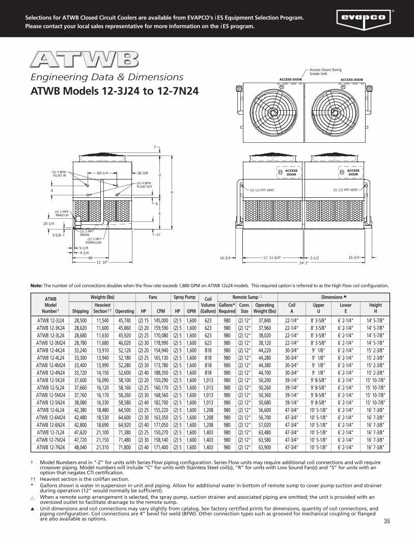
35
Selections for ATWB Closed Circuit Coolers are available from EVAPCO’s iES Equipment Selection Program.
Please contact your local sales representative for more information on the iES program.
11' 10" 24' 2"11' 11-3/4"
H
E
U
7
(2) 2 MPTMAKE-UP
(2) 3 MPTOVERFLOW
(2) 3 MPTDRAIN
2-1/2
69-1/4 36-3/8
A
25-1/4
3-5/8
5-1/44-1/4
86
17
6
16-3/4
(4) 4 BFWFLUID IN
(4) 4 BFWFLUID OUT
16-3/4
ACCESS DOORACCESS DOOR
ACCESSDOOR
ACCESSDOOR
(2) 1/2 FPT VENT (2) 1/2 FPT VENT
Access Doors SwingInside Unit
P P
† Model Numbers end in “-Z” for units with Series Flow piping configuration. Series Flow units may require additional coil connections and will requirecrossover piping. Model numbers will include “C” for units with Stainless Steel coil(s), “R” for units with Low Sound Fan(s) and “S” for units with anoption that negates CTI certification.
†† Heaviest section is the coil/fan section.* Gallons shown is water in suspension in unit and piping. Allow for additional water in bottom of remote sump to cover pump suction and strainer
during operation (12” would normally be sufficient).�� When a remote sump arrangement is selected, the spray pump, suction strainer and associated piping are omitted; the unit is provided with an
oversized outlet to facilitate drainage to the remote sump.� Unit dimensions and coil connections may vary slightly from catalog. See factory certified prints for dimensions, quantity of coil connections, and
piping configuration. Coil connections are 4” bevel for weld (BFW). Other connection types such as grooved for mechanical coupling or flangedare also available as options.
Note: The number of coil connections doubles when the flow rate exceeds 1,800 GPM on ATWB 12x24 models. This required option is referred to as the High Flow coil configuration.
ATWB CoilModel Heaviest Volume Gallons* Conn. Operating Coil Upper Lower Height
Number† Shipping Section†† Operating HP CFM HP GPM (Gallons) Required Size Weight (lbs) A U E H
ATWB 12-3J24 28,500 11,540 45,740 (2) 15 145,000 (2) 5 1,600 623 980 (2) 12" 37,840 22-1/4" 8' 3-5/8" 6' 2-1/4" 14' 5-7/8"ATWB 12-3K24 28,620 11,600 45,860 (2) 20 159,590 (2) 5 1,600 623 980 (2) 12" 37,960 22-1/4" 8' 3-5/8" 6' 2-1/4" 14' 5-7/8" ATWB 12-3L24 28,680 11,630 45,920 (2) 25 170,080 (2) 5 1,600 623 980 (2) 12" 38,020 22-1/4" 8' 3-5/8" 6' 2-1/4" 14' 5-7/8" ATWB 12-3M24 28,780 11,680 46,020 (2) 30 178,990 (2) 5 1,600 623 980 (2) 12" 38,120 22-1/4" 8' 3-5/8" 6' 2-1/4" 14' 5-7/8" ATWB 12-4K24 33,240 13,910 52,120 (2) 20 154,940 (2) 5 1,600 818 980 (2) 12" 44,220 30-3/4" 9' 1/8" 6' 2-1/4" 15' 2-3/8" ATWB 12-4L24 33,300 13,940 52,180 (2) 25 165,130 (2) 5 1,600 818 980 (2) 12" 44,280 30-3/4" 9' 1/8" 6' 2-1/4" 15' 2-3/8" ATWB 12-4M24 33,400 13,990 52,280 (2) 30 173,780 (2) 5 1,600 818 980 (2) 12" 44,380 30-3/4" 9' 1/8" 6' 2-1/4" 15' 2-3/8" ATWB 12-4N24 33,720 14,150 52,600 (2) 40 188,350 (2) 5 1,600 818 980 (2) 12" 44,700 30-3/4" 9' 1/8" 6' 2-1/4" 15' 2-3/8" ATWB 12-5K24 37,600 16,090 58,100 (2) 20 150,290 (2) 5 1,600 1,013 980 (2) 12" 50,200 39-1/4" 9' 8-5/8" 6' 2-1/4" 15' 10-7/8" ATWB 12-5L24 37,660 16,120 58,160 (2) 25 160,170 (2) 5 1,600 1,013 980 (2) 12" 50,260 39-1/4" 9' 8-5/8" 6' 2-1/4" 15' 10-7/8" ATWB 12-5M24 37,760 16,170 58,260 (2) 30 168,560 (2) 5 1,600 1,013 980 (2) 12" 50,360 39-1/4" 9' 8-5/8" 6' 2-1/4" 15' 10-7/8" ATWB 12-5N24 38,080 16,330 58,580 (2) 40 182,700 (2) 5 1,600 1,013 980 (2) 12" 50,680 39-1/4" 9' 8-5/8" 6' 2-1/4" 15' 10-7/8" ATWB 12-6L24 42,380 18,480 64,500 (2) 25 155,220 (2) 5 1,600 1,208 980 (2) 12" 56,600 47-3/4" 10' 5-1/8" 6' 2-1/4" 16' 7-3/8" ATWB 12-6M24 42,480 18,530 64,600 (2) 30 163,350 (2) 5 1,600 1,208 980 (2) 12" 56,700 47-3/4" 10' 5-1/8" 6' 2-1/4" 16' 7-3/8" ATWB 12-6N24 42,800 18,690 64,920 (2) 40 177,050 (2) 5 1,600 1,208 980 (2) 12" 57,020 47-3/4" 10' 5-1/8" 6' 2-1/4" 16' 7-3/8" ATWB 12-7L24 47,620 21,100 71,380 (2) 25 150,270 (2) 5 1,600 1,403 980 (2) 12" 63,480 47-3/4" 10' 5-1/8" 6' 2-1/4" 16' 7-3/8" ATWB 12-7M24 47,720 21,150 71,480 (2) 30 158,140 (2) 5 1,600 1,403 980 (2) 12" 63,580 47-3/4" 10' 5-1/8" 6' 2-1/4" 16' 7-3/8" ATWB 12-7N24 48,040 21,310 71,800 (2) 40 171,400 (2) 5 1,600 1,403 980 (2) 12" 63,900 47-3/4" 10' 5-1/8" 6' 2-1/4" 16' 7-3/8"
Weights (lbs) Fans Spray Pump Remote Sump �� Dimensions �
Engineering Data & Dimensions
ATWB Models 12-3J24 to 12-7N24

36
11' 10" 28' 2"13' 11-3/4"
H
E
U
7
(2) 2 MPTMAKE-UP
(2) 3 MPTOVERFLOW
(2) 3 MPTDRAIN
2-1/2
69-1/4 36-3/8
A
25-1/4
3-5/8
5-1/44-1/4
86
17
6
16-3/4
(4) 4 BFWFLUID IN
(4) 4 BFWFLUID OUT
16-3/4
ACCESS DOORACCESS DOOR
ACCESSDOOR
ACCESSDOOR
(2) 1/2 FPT VENT (2) 1/2 FPT VENT
Access Doors SwingInside Unit
P P
† Model Numbers end in “-Z” for units with Series Flow piping configuration. Series Flow units may require additional coil connections and will requirecrossover piping. Model numbers will include “C” for units with Stainless Steel coil(s), “R” for units with Low Sound Fan(s) and “S” for units with anoption that negates CTI certification.
†† Heaviest section is the coil/fan section.* Gallons shown is water in suspension in unit and piping. Allow for additional water in bottom of remote sump to cover pump suction and strainer
during operation (12” would normally be sufficient).�� When a remote sump arrangement is selected, the spray pump, suction strainer and associated piping are omitted; the unit is provided with an
oversized outlet to facilitate drainage to the remote sump.� Unit dimensions and coil connections may vary slightly from catalog. See factory certified prints for dimensions, quantity of coil connections, and
piping configuration. Coil connections are 4” bevel for weld (BFW). Other connection types such as grooved for mechanical coupling or flangedare also available as options.
Note: The number of coil connections doubles when the flow rate exceeds 1,800 GPM on ATWB 12x28 models. This required option is referred to as the High Flow coil configuration.
Engineering Data & Dimensions
ATWB Models 12-3K28 to 12-7N28
ATWB CoilModel Heaviest Volume Gallons* Conn. Operating Coil Upper Lower Height
Number† Shipping Section†† Operating HP CFM HP GPM (Gallons) Required Size Weight (lbs) A U E H
ATWB 12-3K28 32,340 13,110 52,580 (2) 20 176,900 (2) 5 1,800 723 1,140 (2) 12" 43,440 22-1/4" 8' 3-5/8" 7' 2-1/4" 15' 5-7/8"ATWB 12-3L28 32,400 13,140 52,640 (2) 25 190,090 (2) 5 1,800 723 1,140 (2) 12" 43,500 22-1/4" 8' 3-5/8" 7' 2-1/4" 15' 5-7/8" ATWB 12-3M28 32,500 13,190 52,740 (2) 30 200,050 (2) 5 1,800 723 1,140 (2) 12" 43,600 22-1/4" 8' 3-5/8" 7' 2-1/4" 15' 5-7/8" ATWB 12-3N28 32,820 13,350 53,060 (2) 40 216,830 (2) 5 1,800 723 1,140 (2) 12" 43,920 22-1/4" 8' 3-5/8" 7' 2-1/4" 15' 5-7/8" ATWB 12-4K28 37,720 15,800 59,860 (2) 20 171,750 (2) 5 1,800 951 1,140 (2) 12" 50,720 30-3/4" 9' 1/8" 7' 2-1/4" 16' 2-3/8" ATWB 12-4L28 37,780 15,830 59,920 (2) 25 184,560 (2) 5 1,800 951 1,140 (2) 12" 50,780 30-3/4" 9' 1/8" 7' 2-1/4" 16' 2-3/8" ATWB 12-4M28 37,880 15,880 60,020 (2) 30 194,220 (2) 5 1,800 951 1,140 (2) 12" 50,880 30-3/4" 9' 1/8" 7' 2-1/4" 16' 2-3/8" ATWB 12-4N28 38,200 16,040 60,340 (2) 40 210,510 (2) 5 1,800 951 1,140 (2) 12" 51,200 30-3/4" 9' 1/8" 7' 2-1/4" 16' 2-3/8" ATWB 12-5L28 42,780 18,330 66,820 (2) 25 179,020 (2) 5 1,800 1,179 1,140 (2) 12" 57,680 39-1/4" 9' 8-5/8" 7' 2-1/4" 16' 10-7/8" ATWB 12-5M28 42,880 18,380 66,920 (2) 30 188,400 (2) 5 1,800 1,179 1,140 (2) 12" 57,780 39-1/4" 9' 8-5/8" 7' 2-1/4" 16' 10-7/8" ATWB 12-5N28 43,200 18,540 67,240 (2) 40 204,200 (2) 5 1,800 1,179 1,140 (2) 12" 58,100 39-1/4" 9' 8-5/8" 7' 2-1/4" 16' 10-7/8" ATWB 12-6L28 48,780 21,330 74,720 (2) 25 173,480 (2) 5 1,800 1,407 1,140 (2) 12" 65,580 47-3/4" 10' 5-1/8" 7' 2-1/4" 17' 7-3/8" ATWB 12-6M28 48,880 21,380 74,820 (2) 30 182,570 (2) 5 1,800 1,407 1,140 (2) 12" 65,680 47-3/4" 10' 5-1/8" 7' 2-1/4" 17' 7-3/8" ATWB 12-6N28 49,200 21,540 75,140 (2) 40 197,880 (2) 5 1,800 1,407 1,140 (2) 12" 66,000 47-3/4" 10' 5-1/8" 7' 2-1/4" 17' 7-3/8" ATWB 12-7L28 54,980 24,430 82,820 (2) 25 167,950 (2) 5 1,800 1,635 1,140 (2) 12" 73,680 47-3/4" 10' 5-1/8" 7' 2-1/4" 17' 7-3/8" ATWB 12-7M28 55,080 24,480 82,920 (2) 30 176,740 (2) 5 1,800 1,635 1,140 (2) 12" 73,780 47-3/4" 10' 5-1/8" 7' 2-1/4" 17' 7-3/8" ATWB 12-7N28 55,400 24,640 83,240 (2) 40 191,570 (2) 5 1,800 1,635 1,140 (2) 12" 74,100 47-3/4" 10' 5-1/8" 7' 2-1/4" 17' 7-3/8"
Weights (lbs) Fans Spray Pump Remote Sump �� Dimensions �

37
Selections for ATWB Closed Circuit Coolers are available from EVAPCO’s iES Equipment Selection Program.
Please contact your local sales representative for more information on the iES program.
11' 10"
18'
36' 2-1/2"
H
E
U
7
(2) 2 MPTMAKE-UP
(2) 3 MPTOVERFLOW
(2) 3 MPTDRAIN
2-1/2
69-1/4 36-3/8
A
25-1/4
3-5/8
5-1/44-1/4
86
17
6
23-1/8 23-1/8
(2) 4 BFWFLUID IN
(2) 4 BFWFLUID OUT
ACCESS DOORACCESS DOOR
ACCESSDOOR
ACCESSDOOR
(2) 1/2 FPT VENT (2) 1/2 FPT VENT
Access Doors SwingInside Unit
P P
† Model Numbers end in “-Z” for units with Series Flow piping configuration. Series Flow units may require additional coil connections and will requirecrossover piping. Model numbers will include “C” for units with Stainless Steel coil(s), “R” for units with Low Sound Fan(s) and “S” for units with anoption that negates CTI certification.
†† Heaviest section is the coil/fan section.* Gallons shown is water in suspension in unit and piping. Allow for additional water in bottom of remote sump to cover pump suction and strainer
during operation (12” would normally be sufficient).�� When a remote sump arrangement is selected, the spray pump, suction strainer and associated piping are omitted; the unit is provided with an
oversized outlet to facilitate drainage to the remote sump.� Unit dimensions and coil connections may vary slightly from catalog. See factory certified prints for dimensions, quantity of coil connections, and
piping configuration. Coil connections are 4” bevel for weld (BFW). Other connection types such as grooved for mechanical coupling or flangedare also available as options.
Note: The number of coil connections doubles when the flow rate exceeds 1,800 GPM on ATWB 12x36 models. This required option is referred to as the High Flow coil configuration.
ATWB CoilModel Heaviest Volume Gallons* Conn. Operating Coil Upper Lower Height
Number† Shipping Section†† Operating HP CFM HP GPM (Gallons) Required Size Weight (lbs) A U E H
ATWB 12-3K36 40,520 16,340 66,400 (2) 20 216,080 (2) 7.5 2,400 922 1,440 (2) 12" 54,660 22-1/4" 8' 3-5/8" 7' 2-1/4" 15' 5-7/8"ATWB 12-3L36 40,580 16,370 66,460 (2) 25 232,770 (2) 7.5 2,400 922 1,440 (2) 12" 54,720 22-1/4" 8' 3-5/8" 7' 2-1/4" 15' 5-7/8" ATWB 12-3M36 40,680 16,420 66,560 (2) 30 247,350 (2) 7.5 2,400 922 1,440 (2) 12" 54,820 22-1/4" 8' 3-5/8" 7' 2-1/4" 15' 5-7/8" ATWB 12-3N36 41,000 16,580 66,880 (2) 40 268,450 (2) 7.5 2,400 922 1,440 (2) 12" 55,140 22-1/4" 8' 3-5/8" 7' 2-1/4" 15' 5-7/8" ATWB 12-4K36 47,380 19,770 75,720 (2) 20 209,790 (2) 7.5 2,400 1,216 1,440 (2) 12" 63,980 30-3/4" 9' 1/8" 7' 2-1/4" 16' 2-3/8" ATWB 12-4L36 47,440 19,800 75,780 (2) 25 225,990 (2) 7.5 2,400 1,216 1,440 (2) 12" 64,040 30-3/4" 9' 1/8" 7' 2-1/4" 16' 2-3/8" ATWB 12-4M36 47,540 19,850 75,880 (2) 30 240,150 (2) 7.5 2,400 1,216 1,440 (2) 12" 64,140 30-3/4" 9' 1/8" 7' 2-1/4" 16' 2-3/8" ATWB 12-4N36 47,860 20,010 76,200 (2) 40 260,630 (2) 7.5 2,400 1,216 1,440 (2) 12" 64,460 30-3/4" 9' 1/8" 7' 2-1/4" 16' 2-3/8" ATWB 12-4O36 47,880 20,020 76,220 (2) 50 277,440 (2) 7.5 2,400 1,216 1,440 (2) 12" 64,480 30-3/4" 9' 1/8" 7' 2-1/4" 16' 2-3/8" ATWB 12-5L36 54,040 23,100 84,820 (2) 25 219,210 (2) 7.5 2,400 1,510 1,440 (2) 12" 73,080 39-1/4" 9' 8-5/8" 7' 2-1/4" 16' 10-7/8" ATWB 12-5M36 54,140 23,150 84,920 (2) 30 232,940 (2) 7.5 2,400 1,510 1,440 (2) 12" 73,180 39-1/4" 9' 8-5/8" 7' 2-1/4" 16' 10-7/8" ATWB 12-5N36 54,460 23,310 85,240 (2) 40 252,810 (2) 7.5 2,400 1,510 1,440 (2) 12" 73,500 39-1/4" 9' 8-5/8" 7' 2-1/4" 16' 10-7/8" ATWB 12-5O36 54,480 23,320 85,260 (2) 50 269,110 (2) 7.5 2,400 1,510 1,440 (2) 12" 73,520 39-1/4" 9' 8-5/8" 7' 2-1/4" 16' 10-7/8" ATWB 12-6M36 60,920 26,540 94,160 (2) 30 225,740 (2) 7.5 2,400 1,805 1,440 (2) 12" 82,420 47-3/4" 10' 5-1/8" 7' 2-1/4" 17' 7-3/8" ATWB 12-6N36 61,240 26,700 94,480 (2) 40 244,990 (2) 7.5 2,400 1,805 1,440 (2) 12" 82,740 47-3/4" 10' 5-1/8" 7' 2-1/4" 17' 7-3/8" ATWB 12-6O36 61,260 26,710 94,500 (2) 50 260,790 (2) 7.5 2,400 1,805 1,440 (2) 12" 82,760 47-3/4" 10' 5-1/8" 7' 2-1/4" 17' 7-3/8" ATWB 12-6P36 61,660 26,910 94,900 (2) 60 274,450 (2) 7.5 2,400 1,805 1,440 (2) 12" 83,160 47-3/4" 10' 5-1/8" 7' 2-1/4" 17' 7-3/8" ATWB 12-7M36 68,760 30,460 104,460 (2) 30 218,530 (2) 7.5 2,400 2,099 1,440 (2) 12" 92,720 47-3/4" 10' 5-1/8" 7' 2-1/4" 17' 7-3/8" ATWB 12-7N36 69,080 30,620 104,780 (2) 40 237,170 (2) 7.5 2,400 2,099 1,440 (2) 12" 93,040 47-3/4" 10' 5-1/8" 7' 2-1/4" 17' 7-3/8" ATWB 12-7O36 69,100 30,630 104,800 (2) 50 252,470 (2) 7.5 2,400 2,099 1,440 (2) 12" 93,060 47-3/4" 10' 5-1/8" 7' 2-1/4" 17' 7-3/8" ATWB 12-7P36 69,500 30,830 105,200 (2) 60 265,690 (2) 7.5 2,400 2,099 1,440 (2) 12" 93,460 47-3/4" 10' 5-1/8" 7' 2-1/4" 17' 7-3/8"
Weights (lbs) Fans Spray Pump Remote Sump �� Dimensions �
Engineering Data & Dimensions
ATWB Models 12-3K36 to 12-7P36

38
11' 10" 40' 2-1/2"
20'
H
E
U
7
(2) 2 MPTMAKE-UP
(2) 3 MPTOVERFLOW
(2) 3 MPTDRAIN
2-1/2
69-1/4 36-3/8
A
25-1/4
3-5/8
5-1/44-1/4
86
17
6
24-1/2 24-1/2
(2) 4 BFWFLUID IN
(2) 4 BFWFLUID OUT
ACCESS DOORACCESS DOOR
ACCESSDOOR
ACCESSDOOR
(2) 1/2 FPT VENT (2) 1/2 FPT VENT
Access Doors SwingInside Unit
P P
† Model Numbers end in “-Z” for units with Series Flow piping configuration. Series Flow units may require additional coil connections and willrequire crossover piping. Model numbers will include “C” for units with Stainless Steel coil(s), “R” for units with Low Sound Fan(s) and “S” for unitswith an option that negates CTI certification.
†† Heaviest section is the coil/fan section.* Gallons shown is water in suspension in unit and piping. Allow for additional water in bottom of remote sump to cover pump suction and
strainer during operation (12” would normally be sufficient).�� When a remote sump arrangement is selected, the spray pump, suction strainer and associated piping are omitted; the unit is provided with an
oversized outlet to facilitate drainage to the remote sump.� Unit dimensions and coil connections may vary slightly from catalog. See factory certified prints for dimensions, quantity of coil connections,
and piping configuration. Coil connections are 4” bevel for weld (BFW). Other connection types such as grooved for mechanical coupling orflanged are also available as options.
Note: The number of coil connections doubles when the flow rate exceeds 1,800 GPM on ATWB 12x40 models. This required option is referred to as the High Flow coil configuration.
Engineering Data & Dimensions
ATWB Models 12-3L40 to 12-7P40
ATWB CoilModel Heaviest Volume Gallons* Conn. Operating Coil Upper Lower Height
Number† Shipping Section†† Operating HP CFM HP GPM (Gallons) Required Size Weight (lbs) A U E H
ATWB 12-3L40 44,720 17,850 73,660 (2) 25 249,720 (2) 10 2,800 1,021 1,600 (2) 14" 60,260 22-1/4" 8' 3-5/8" 7' 2-1/4" 15' 5-7/8"ATWB 12-3M40 44,820 17,900 73,760 (2) 30 265,370 (2) 10 2,800 1,021 1,600 (2) 14" 60,360 22-1/4" 8' 3-5/8" 7' 2-1/4" 15' 5-7/8" ATWB 12-3N40 45,140 18,060 74,080 (2) 40 289,620 (2) 10 2,800 1,021 1,600 (2) 14" 60,680 22-1/4" 8' 3-5/8" 7' 2-1/4" 15' 5-7/8" ATWB 12-3O40 45,160 18,070 74,100 (2) 50 308,300 (2) 10 2,800 1,021 1,600 (2) 14" 60,700 22-1/4" 8' 3-5/8" 7' 2-1/4" 15' 5-7/8" ATWB 12-4L40 52,280 21,630 83,960 (2) 25 242,450 (2) 10 2,800 1,349 1,600 (2) 14" 70,560 30-3/4" 9' 1/8" 7' 2-1/4" 16' 2-3/8" ATWB 12-4M40 52,380 21,680 84,060 (2) 30 257,640 (2) 10 2,800 1,349 1,600 (2) 14" 70,660 30-3/4" 9' 1/8" 7' 2-1/4" 16' 2-3/8" ATWB 12-4N40 52,700 21,840 84,380 (2) 40 281,190 (2) 10 2,800 1,349 1,600 (2) 14" 70,980 30-3/4" 9' 1/8" 7' 2-1/4" 16' 2-3/8" ATWB 12-4O40 52,720 21,850 84,400 (2) 50 299,320 (2) 10 2,800 1,349 1,600 (2) 14" 71,000 30-3/4" 9' 1/8" 7' 2-1/4" 16' 2-3/8" ATWB 12-5M40 59,740 25,360 94,160 (2) 30 249,910 (2) 10 2,800 1,676 1,600 (2) 14" 80,760 39-1/4" 9' 8-5/8" 7' 2-1/4" 16' 10-7/8" ATWB 12-5N40 60,060 25,520 94,480 (2) 40 272,750 (2) 10 2,800 1,676 1,600 (2) 14" 81,080 39-1/4" 9' 8-5/8" 7' 2-1/4" 16' 10-7/8" ATWB 12-5O40 60,080 25,530 94,500 (2) 50 290,340 (2) 10 2,800 1,676 1,600 (2) 14" 81,100 39-1/4" 9' 8-5/8" 7' 2-1/4" 16' 10-7/8" ATWB 12-5P40 60,480 25,730 94,900 (2) 60 305,540 (2) 10 2,800 1,676 1,600 (2) 14" 81,500 39-1/4" 9' 8-5/8" 7' 2-1/4" 16' 10-7/8" ATWB 12-6N40 68,360 29,670 105,500 (2) 40 264,320 (2) 10 2,800 2,004 1,600 (2) 14" 92,100 47-3/4" 10' 5-1/8" 7' 2-1/4" 17' 7-3/8" ATWB 12-6O40 68,380 29,680 105,520 (2) 50 281,360 (2) 10 2,800 2,004 1,600 (2) 14" 92,120 47-3/4" 10' 5-1/8" 7' 2-1/4" 17' 7-3/8" ATWB 12-6P40 68,780 29,880 105,920 (2) 60 296,090 (2) 10 2,800 2,004 1,600 (2) 14" 92,520 47-3/4" 10' 5-1/8" 7' 2-1/4" 17' 7-3/8" ATWB 12-7N40 77,220 34,100 117,100 (2) 40 255,880 (2) 10 2,800 2,331 1,600 (2) 14" 103,700 47-3/4" 10' 5-1/8" 7' 2-1/4" 17' 7-3/8" ATWB 12-7O40 77,240 34,110 117,120 (2) 50 272,380 (2) 10 2,800 2,331 1,600 (2) 14" 103,720 47-3/4" 10' 5-1/8" 7' 2-1/4" 17' 7-3/8" ATWB 12-7P40 77,640 34,310 117,520 (2) 60 286,650 (2) 10 2,800 2,331 1,600 (2) 14" 104,120 47-3/4" 10' 5-1/8" 7' 2-1/4" 17' 7-3/8"
Weights (lbs) Fans Spray Pump Remote Sump �� Dimensions �

39
Selections for ATWB Closed Circuit Coolers are available from EVAPCO’s iES Equipment Selection Program.
Please contact your local sales representative for more information on the iES program.
24' 1-1/8" 11' 11-3/4"1425-1/8
136-3/4137-3/4
25-1/417
3-5/8
(2) 2 MPTMAKE-UP
(2) 3 MPTOVERFLOW
(2) 2 MPTDRAIN
E
U
H
7
36-3/8
69-1/4
A
56
6
18-1/2
(4) 4 BFWFLUID IN
(4) 4 BFWFLUID OUT
ACCESS DOOR
ACCESS DOOR
ACCESSDOOR
ACCESSDOOR
(4) 1/2 FPT VENT
Access Doors SwingInside Unit
P
P
† Model Numbers end in “-Z” for units with Series Flow piping configuration. Series Flow units may require additional coil connections and will requirecrossover piping. Model numbers will include “C” for units with Stainless Steel coil(s), “R” for units with Low Sound Fan(s) and “S” for units with anoption that negates CTI certification.
†† Heaviest section is the coil/fan section.* Gallons shown is water in suspension in unit and piping. Allow for additional water in bottom of remote sump to cover pump suction and strainer
during operation (12” would normally be sufficient).�� When a remote sump arrangement is selected, the spray pump, suction strainer and associated piping are omitted; the unit is provided with an
oversized outlet to facilitate drainage to the remote sump.� Unit dimensions and coil connections may vary slightly from catalog. See factory certified prints for dimensions, quantity of coil connections, and
piping configuration. Coil connections are 4” bevel for weld (BFW). Other connection types such as grooved for mechanical coupling or flangedare also available as options.
Note: The number of coil connections doubles when the flow rate exceeds 1,800 GPM on ATWB 24x12 models. This required option is referred to as the High Flow coil configuration.
ATWB CoilModel Heaviest Volume Gallons* Conn. Operating Coil Upper Lower Height
Number† Shipping Section†† Operating HP CFM HP GPM (Gallons) Required Size Weight (lbs) A U E H
ATWB 24-3J12 28,500 11,540 45,740 (2) 15 145,000 (2) 5 1,600 623 980 (2) 12" 37,840 22-1/4" 8' 3-5/8" 6' 2-1/4" 14' 5-7/8"ATWB 24-3K12 28,620 11,600 45,860 (2) 20 159,590 (2) 5 1,600 623 980 (2) 12" 37,960 22-1/4" 8' 3-5/8" 6' 2-1/4" 14' 5-7/8" ATWB 24-3L12 28,680 11,630 45,920 (2) 25 170,080 (2) 5 1,600 623 980 (2) 12" 38,020 22-1/4" 8' 3-5/8" 6' 2-1/4" 14' 5-7/8" ATWB 24-3M12 28,780 11,680 46,020 (2) 30 178,990 (2) 5 1,600 623 980 (2) 12" 38,120 22-1/4" 8' 3-5/8" 6' 2-1/4" 14' 5-7/8" ATWB 24-4K12 33,240 13,910 52,120 (2) 20 154,940 (2) 5 1,600 818 980 (2) 12" 44,220 30-3/4" 9' 1/8" 6' 2-1/4" 15' 2-3/8" ATWB 24-4L12 33,300 13,940 52,180 (2) 25 165,130 (2) 5 1,600 818 980 (2) 12" 44,280 30-3/4" 9' 1/8" 6' 2-1/4" 15' 2-3/8" ATWB 24-4M12 33,400 13,990 52,280 (2) 30 173,780 (2) 5 1,600 818 980 (2) 12" 44,380 30-3/4" 9' 1/8" 6' 2-1/4" 15' 2-3/8" ATWB 24-4N12 33,720 14,150 52,600 (2) 40 188,350 (2) 5 1,600 818 980 (2) 12" 44,700 30-3/4" 9' 1/8" 6' 2-1/4" 15' 2-3/8" ATWB 24-5K12 37,600 16,090 58,100 (2) 20 150,290 (2) 5 1,600 1,013 980 (2) 12" 50,200 39-1/4" 9' 8-5/8" 6' 2-1/4" 15' 10-7/8" ATWB 24-5L12 37,660 16,120 58,160 (2) 25 160,170 (2) 5 1,600 1,013 980 (2) 12" 50,260 39-1/4" 9' 8-5/8" 6' 2-1/4" 15' 10-7/8" ATWB 24-5M12 37,760 16,170 58,260 (2) 30 168,560 (2) 5 1,600 1,013 980 (2) 12" 50,360 39-1/4" 9' 8-5/8" 6' 2-1/4" 15' 10-7/8" ATWB 24-5N12 38,080 16,330 58,580 (2) 40 182,700 (2) 5 1,600 1,013 980 (2) 12" 50,680 39-1/4" 9' 8-5/8" 6' 2-1/4" 15' 10-7/8" ATWB 24-6L12 42,380 18,480 64,500 (2) 25 155,220 (2) 5 1,600 1,208 980 (2) 12" 56,600 47-3/4" 10' 5-1/8" 6' 2-1/4" 16' 7-3/8" ATWB 24-6M12 42,480 18,530 64,600 (2) 30 163,350 (2) 5 1,600 1,208 980 (2) 12" 56,700 47-3/4" 10' 5-1/8" 6' 2-1/4" 16' 7-3/8" ATWB 24-6N12 42,800 18,690 64,920 (2) 40 177,050 (2) 5 1,600 1,208 980 (2) 12" 57,020 47-3/4" 10' 5-1/8" 6' 2-1/4" 16' 7-3/8" ATWB 24-7L12 47,620 21,100 71,380 (2) 25 150,270 (2) 5 1,600 1,403 980 (2) 12" 63,480 47-3/4" 10' 5-1/8" 6' 2-1/4" 16' 7-3/8" ATWB 24-7M12 47,720 21,150 71,480 (2) 30 158,140 (2) 5 1,600 1,403 980 (2) 12" 63,580 47-3/4" 10' 5-1/8" 6' 2-1/4" 16' 7-3/8" ATWB 24-7N12 48,040 21,310 71,800 (2) 40 171,400 (2) 5 1,600 1,403 980 (2) 12" 63,900 47-3/4" 10' 5-1/8" 6' 2-1/4" 16' 7-3/8"
Weights (lbs) Fans Spray Pump Remote Sump �� Dimensions �
Engineering Data & Dimensions
ATWB Models 24-3J12 to 24-7N12

40
24' 1-1/8" 13' 11-3/4"1425-1/8
136-3/4137-3/4
25-1/417
3-5/8
(2) 2 MPTMAKE-UP
(2) 3 MPTOVERFLOW
(2) 2 MPTDRAIN
E
U
H
7
36-3/8
69-1/4
A
56
6
18-1/2
(4) 4 BFWFLUID IN
(4) 4 BFWFLUID OUT
ACCESS DOOR
ACCESS DOOR
ACCESSDOOR
ACCESSDOOR
(4) 1/2 FPT VENT
Access Doors SwingInside Unit
P
P
† Model Numbers end in “-Z” for units with Series Flow piping configuration. Series Flow units may require additional coil connections and will requirecrossover piping. Model numbers will include “C” for units with Stainless Steel coil(s), “R” for units with Low Sound Fan(s) and “S” for units with anoption that negates CTI certification.
†† Heaviest section is the coil/fan section.* Gallons shown is water in suspension in unit and piping. Allow for additional water in bottom of remote sump to cover pump suction and strainer
during operation (12” would normally be sufficient).�� When a remote sump arrangement is selected, the spray pump, suction strainer and associated piping are omitted; the unit is provided with an
oversized outlet to facilitate drainage to the remote sump.� Unit dimensions and coil connections may vary slightly from catalog. See factory certified prints for dimensions, quantity of coil connections, and
piping configuration. Coil connections are 4” bevel for weld (BFW). Other connection types such as grooved for mechanical coupling or flanged arealso available as options.
Note: The number of coil connections doubles when the flow rate exceeds 1,800 GPM on ATWB 24x14 models. This required option is referred to as the High Flow coil configuration.
Engineering Data & Dimensions
ATWB Models 24-3K14 to 24-7N14
ATWB CoilModel Heaviest Volume Gallons* Conn. Operating Coil Upper Lower Height
Number† Shipping Section†† Operating HP CFM HP GPM (Gallons) Required Size Weight (lbs) A U E H
ATWB 24-3K14 32,340 13,110 52,580 (2) 20 176,900 (2) 5 1,800 723 1,140 (2) 12" 43,440 22-1/4" 8' 3-5/8" 7' 2-1/4" 15' 5-7/8"ATWB 24-3L14 32,400 13,140 52,640 (2) 25 190,090 (2) 5 1,800 723 1,140 (2) 12" 43,500 22-1/4" 8' 3-5/8" 7' 2-1/4" 15' 5-7/8" ATWB 24-3M14 32,500 13,190 52,740 (2) 30 200,050 (2) 5 1,800 723 1,140 (2) 12" 43,600 22-1/4" 8' 3-5/8" 7' 2-1/4" 15' 5-7/8" ATWB 24-3N14 32,820 13,350 53,060 (2) 40 216,830 (2) 5 1,800 723 1,140 (2) 12" 43,920 22-1/4" 8' 3-5/8" 7' 2-1/4" 15' 5-7/8" ATWB 24-4K14 37,720 15,800 59,860 (2) 20 171,750 (2) 5 1,800 951 1,140 (2) 12" 50,720 30-3/4" 9' 1/8" 7' 2-1/4" 16' 2-3/8" ATWB 24-4L14 37,780 15,830 59,920 (2) 25 184,560 (2) 5 1,800 951 1,140 (2) 12" 50,780 30-3/4" 9' 1/8" 7' 2-1/4" 16' 2-3/8" ATWB 24-4M14 37,880 15,880 60,020 (2) 30 194,220 (2) 5 1,800 951 1,140 (2) 12" 50,880 30-3/4" 9' 1/8" 7' 2-1/4" 16' 2-3/8" ATWB 24-4N14 38,200 16,040 60,340 (2) 40 210,510 (2) 5 1,800 951 1,140 (2) 12" 51,200 30-3/4" 9' 1/8" 7' 2-1/4" 16' 2-3/8" ATWB 24-5L14 42,780 18,330 66,820 (2) 25 179,020 (2) 5 1,800 1,179 1,140 (2) 12" 57,680 39-1/4" 9' 8-5/8" 7' 2-1/4" 16' 10-7/8" ATWB 24-5M14 42,880 18,380 66,920 (2) 30 188,400 (2) 5 1,800 1,179 1,140 (2) 12" 57,780 39-1/4" 9' 8-5/8" 7' 2-1/4" 16' 10-7/8" ATWB 24-5N14 43,200 18,540 67,240 (2) 40 204,200 (2) 5 1,800 1,179 1,140 (2) 12" 58,100 39-1/4" 9' 8-5/8" 7' 2-1/4" 16' 10-7/8" ATWB 24-6L14 48,780 21,330 74,720 (2) 25 173,480 (2) 5 1,800 1,407 1,140 (2) 12" 65,580 47-3/4" 10' 5-1/8" 7' 2-1/4" 17' 7-3/8" ATWB 24-6M14 48,880 21,380 74,820 (2) 30 182,570 (2) 5 1,800 1,407 1,140 (2) 12" 65,680 47-3/4" 10' 5-1/8" 7' 2-1/4" 17' 7-3/8" ATWB 24-6N14 49,200 21,540 75,140 (2) 40 197,880 (2) 5 1,800 1,407 1,140 (2) 12" 66,000 47-3/4" 10' 5-1/8" 7' 2-1/4" 17' 7-3/8" ATWB 24-7L14 54,980 24,430 82,820 (2) 25 167,950 (2) 5 1,800 1,635 1,140 (2) 12" 73,680 47-3/4" 10' 5-1/8" 7' 2-1/4" 17' 7-3/8" ATWB 24-7M14 55,080 24,480 82,920 (2) 30 176,740 (2) 5 1,800 1,635 1,140 (2) 12" 73,780 47-3/4" 10' 5-1/8" 7' 2-1/4" 17' 7-3/8" ATWB 24-7N14 55,400 24,640 83,240 (2) 40 191,570 (2) 5 1,800 1,635 1,140 (2) 12" 74,100 47-3/4" 10' 5-1/8" 7' 2-1/4" 17' 7-3/8"
Weights (lbs) Fans Spray Pump Remote Sump �� Dimensions �

24' 1-1/8" 18' 0"1425-1/8
136-3/4137-3/4
25-1/417
3-5/8
(2) 2 MPTMAKE-UP
(2) 3 MPTOVERFLOW
(2) 2 MPTDRAIN
E
U
H
36-3/869-1/4
A
56
6
23-1/8
(4) 4 BFWFLUID IN
(4) 4 BFWFLUID OUT
ACCESS DOOR
ACCESS DOOR
ACCESSDOOR
ACCESSDOOR
(4) 1/2 FPT VENT
Access Doors SwingInside Unit
P
P
41
Selections for ATWB Closed Circuit Coolers are available from EVAPCO’s iES Equipment Selection Program.
Please contact your local sales representative for more information on the iES program.
† Model Numbers end in “-Z” for units with Series Flow piping configuration. Series Flow units may require additional coil connections and will requirecrossover piping. Model numbers will include “C” for units with Stainless Steel coil(s), “R” for units with Low Sound Fan(s) and “S” for units with anoption that negates CTI certification.
†† Heaviest section is the coil/fan section.* Gallons shown is water in suspension in unit and piping. Allow for additional water in bottom of remote sump to cover pump suction and strainer
during operation (12” would normally be sufficient).�� When a remote sump arrangement is selected, the spray pump, suction strainer and associated piping are omitted; the unit is provided with an
oversized outlet to facilitate drainage to the remote sump.� Unit dimensions and coil connections may vary slightly from catalog. See factory certified prints for dimensions, quantity of coil connections, and
piping configuration. Coil connections are 4” bevel for weld (BFW). Other connection types such as grooved for mechanical coupling or flangedare also available as options.
Note: The number of coil connections doubles when the flow rate exceeds 1,800 GPM on ATWB 24x18 models. This required option is referred to as the High Flow coil configuration.
ATWB CoilModel Heaviest Volume Gallons* Conn. Operating Coil Upper Lower Height
Number† Shipping Section†† Operating HP CFM HP GPM (Gallons) Required Size Weight (lbs) A U E H
ATWB 24-3K18 40,520 16,340 66,400 (2) 20 216,080 (2) 7.5 2,400 922 1,440 (2) 12" 54,660 22-1/4" 8' 3-5/8" 8' 2-1/4" 16' 5-7/8"ATWB 24-3L18 40,580 16,370 66,460 (2) 25 232,770 (2) 7.5 2,400 922 1,440 (2) 12" 54,720 22-1/4" 8' 3-5/8" 8' 2-1/4" 16' 5-7/8" ATWB 24-3M18 40,680 16,420 66,560 (2) 30 247,350 (2) 7.5 2,400 922 1,440 (2) 12" 54,820 22-1/4" 8' 3-5/8" 8' 2-1/4" 16' 5-7/8" ATWB 24-3N18 41,000 16,580 66,880 (2) 40 268,450 (2) 7.5 2,400 922 1,440 (2) 12" 55,140 22-1/4" 8' 3-5/8" 8' 2-1/4" 16' 5-7/8" ATWB 24-4K18 47,380 19,770 75,720 (2) 20 209,790 (2) 7.5 2,400 1,216 1,440 (2) 12" 63,980 30-3/4" 9' 1/8" 8' 2-1/4" 17' 2-3/8" ATWB 24-4L18 47,440 19,800 75,780 (2) 25 225,990 (2) 7.5 2,400 1,216 1,440 (2) 12" 64,040 30-3/4" 9' 1/8" 8' 2-1/4" 17' 2-3/8" ATWB 24-4M18 47,540 19,850 75,880 (2) 30 240,150 (2) 7.5 2,400 1,216 1,440 (2) 12" 64,140 30-3/4" 9' 1/8" 8' 2-1/4" 17' 2-3/8" ATWB 24-4N18 47,860 20,010 76,200 (2) 40 260,630 (2) 7.5 2,400 1,216 1,440 (2) 12" 64,460 30-3/4" 9' 1/8" 8' 2-1/4" 17' 2-3/8" ATWB 24-4O18 47,880 20,020 76,220 (2) 50 277,440 (2) 7.5 2,400 1,216 1,440 (2) 12" 64,480 30-3/4" 9' 1/8" 8' 2-1/4" 17' 2-3/8" ATWB 24-5L18 54,040 23,100 84,820 (2) 25 219,210 (2) 7.5 2,400 1,510 1,440 (2) 12" 73,080 39-1/4" 9' 8-5/8" 8' 2-1/4" 17' 10-7/8" ATWB 24-5M18 54,140 23,150 84,920 (2) 30 232,940 (2) 7.5 2,400 1,510 1,440 (2) 12" 73,180 39-1/4" 9' 8-5/8" 8' 2-1/4" 17' 10-7/8" ATWB 24-5N18 54,460 23,310 85,240 (2) 40 252,810 (2) 7.5 2,400 1,510 1,440 (2) 12" 73,500 39-1/4" 9' 8-5/8" 8' 2-1/4" 17' 10-7/8" ATWB 24-5O18 54,480 23,320 85,260 (2) 50 269,110 (2) 7.5 2,400 1,510 1,440 (2) 12" 73,520 39-1/4" 9' 8-5/8" 8' 2-1/4" 17' 10-7/8" ATWB 24-6M18 60,920 26,540 94,160 (2) 30 225,740 (2) 7.5 2,400 1,805 1,440 (2) 12" 82,420 47-3/4" 10' 5-1/8" 8' 2-1/4" 18' 7-3/8" ATWB 24-6N18 61,240 26,700 94,480 (2) 40 244,990 (2) 7.5 2,400 1,805 1,440 (2) 12" 82,740 47-3/4" 10' 5-1/8" 8' 2-1/4" 18' 7-3/8" ATWB 24-6O18 61,260 26,710 94,500 (2) 50 260,790 (2) 7.5 2,400 1,805 1,440 (2) 12" 82,760 47-3/4" 10' 5-1/8" 8' 2-1/4" 18' 7-3/8" ATWB 24-6P18 61,660 26,910 94,900 (2) 60 274,450 (2) 7.5 2,400 1,805 1,440 (2) 12" 83,160 47-3/4" 10' 5-1/8" 8' 2-1/4" 18' 7-3/8" ATWB 24-7M18 68,760 30,460 104,460 (2) 30 218,530 (2) 7.5 2,400 2,099 1,440 (2) 12" 92,720 47-3/4" 10' 5-1/8" 8' 2-1/4" 18' 7-3/8" ATWB 24-7N18 69,080 30,620 104,780 (2) 40 237,170 (2) 7.5 2,400 2,099 1,440 (2) 12" 93,040 47-3/4" 10' 5-1/8" 8' 2-1/4" 18' 7-3/8" ATWB 24-7O18 69,100 30,630 104,800 (2) 50 252,470 (2) 7.5 2,400 2,099 1,440 (2) 12" 93,060 47-3/4" 10' 5-1/8" 8' 2-1/4" 18' 7-3/8" ATWB 24-7P18 69,500 30,830 105,200 (2) 60 265,690 (2) 7.5 2,400 2,099 1,440 (2) 12" 93,460 47-3/4" 10' 5-1/8" 8' 2-1/4" 18' 7-3/8"
Weights (lbs) Fans Spray Pump Remote Sump �� Dimensions �
Engineering Data & Dimensions
ATWB Models 24-3K18 to 24-7P18

42
24' 1-1/8" 20' 0"1425-1/8
136-3/4137-3/4
25-1/417
3-5/8
(2) 2 MPTMAKE-UP
(2) 3 MPTOVERFLOW
(2) 2 MPTDRAIN
E
U
H
36-3/869-1/4
A
56
6
25-5/8
(4) 4 BFWFLUID IN
(4) 4 BFWFLUID OUT
ACCESS DOOR
ACCESS DOOR
ACCESSDOOR
ACCESSDOOR
(4) 1/2 FPT VENT
Access Doors SwingInside Unit
P
P
† Model Numbers end in “-Z” for units with Series Flow piping configuration. Series Flow units may require additional coil connections and will requirecrossover piping. Model numbers will include “C” for units with Stainless Steel coil(s), “R” for units with Low Sound Fan(s) and “S” for units with anoption that negates CTI certification.
†† Heaviest section is the coil/fan section.* Gallons shown is water in suspension in unit and piping. Allow for additional water in bottom of remote sump to cover pump suction and strainer
during operation (12” would normally be sufficient).�� When a remote sump arrangement is selected, the spray pump, suction strainer and associated piping are omitted; the unit is provided with an
oversized outlet to facilitate drainage to the remote sump.� Unit dimensions and coil connections may vary slightly from catalog. See factory certified prints for dimensions, quantity of coil connections, and
piping configuration. Coil connections are 4” bevel for weld (BFW). Other connection types such as grooved for mechanical coupling or flanged arealso available as options.
Note: The number of coil connections doubles when the flow rate exceeds 1,800 GPM on ATWB 24x20 models. This required option is referred to as the High Flow coil configuration.
Engineering Data & Dimensions
ATWB Models 24-3L20 to 24-7P20
ATWB CoilModel Heaviest Volume Gallons* Conn. Operating Coil Upper Lower Height
Number† Shipping Section†† Operating HP CFM HP GPM (Gallons) Required Size Weight (lbs) A U E H
ATWB 24-3L20 44,720 17,850 73,660 (2) 25 249,720 (2) 10 2,800 1,021 1,600 (2) 14" 60,260 22-1/4" 8' 3-5/8" 8' 2-1/4" 16' 5-7/8"ATWB 24-3M20 44,820 17,900 73,760 (2) 30 265,370 (2) 10 2,800 1,021 1,600 (2) 14" 60,360 22-1/4" 8' 3-5/8" 8' 2-1/4" 16' 5-7/8" ATWB 24-3N20 45,140 18,060 74,080 (2) 40 289,620 (2) 10 2,800 1,021 1,600 (2) 14" 60,680 22-1/4" 8' 3-5/8" 8' 2-1/4" 16' 5-7/8" ATWB 24-3O20 45,160 18,070 74,100 (2) 50 308,300 (2) 10 2,800 1,021 1,600 (2) 14" 60,700 22-1/4" 8' 3-5/8" 8' 2-1/4" 16' 5-7/8" ATWB 24-4L20 52,280 21,630 83,960 (2) 25 242,450 (2) 10 2,800 1,349 1,600 (2) 14" 70,560 30-3/4" 9' 1/8" 8' 2-1/4" 17' 2-3/8" ATWB 24-4M20 52,380 21,680 84,060 (2) 30 257,640 (2) 10 2,800 1,349 1,600 (2) 14" 70,660 30-3/4" 9' 1/8" 8' 2-1/4" 17' 2-3/8" ATWB 24-4N20 52,700 21,840 84,380 (2) 40 281,190 (2) 10 2,800 1,349 1,600 (2) 14" 70,980 30-3/4" 9' 1/8" 8' 2-1/4" 17' 2-3/8" ATWB 24-4O20 52,720 21,850 84,400 (2) 50 299,320 (2) 10 2,800 1,349 1,600 (2) 14" 71,000 30-3/4" 9' 1/8" 8' 2-1/4" 17' 2-3/8" ATWB 24-5M20 59,740 25,360 94,160 (2) 30 249,910 (2) 10 2,800 1,676 1,600 (2) 14" 80,760 39-1/4" 9' 8-5/8" 8' 2-1/4" 17' 10-7/8" ATWB 24-5N20 60,060 25,520 94,480 (2) 40 272,750 (2) 10 2,800 1,676 1,600 (2) 14" 81,080 39-1/4" 9' 8-5/8" 8' 2-1/4" 17' 10-7/8" ATWB 24-5O20 60,080 25,530 94,500 (2) 50 290,340 (2) 10 2,800 1,676 1,600 (2) 14" 81,100 39-1/4" 9' 8-5/8" 8' 2-1/4" 17' 10-7/8" ATWB 24-5P20 60,480 25,730 94,900 (2) 60 305,540 (2) 10 2,800 1,676 1,600 (2) 14" 81,500 39-1/4" 9' 8-5/8" 8' 2-1/4" 17' 10-7/8" ATWB 24-6N20 68,360 29,670 105,500 (2) 40 264,320 (2) 10 2,800 2,004 1,600 (2) 14" 92,100 47-3/4" 10' 5-1/8" 8' 2-1/4" 18' 7-3/8" ATWB 24-6O20 68,380 29,680 105,520 (2) 50 281,360 (2) 10 2,800 2,004 1,600 (2) 14" 92,120 47-3/4" 10' 5-1/8" 8' 2-1/4" 18' 7-3/8" ATWB 24-6P20 68,780 29,880 105,920 (2) 60 296,090 (2) 10 2,800 2,004 1,600 (2) 14" 92,520 47-3/4" 10' 5-1/8" 8' 2-1/4" 18' 7-3/8" ATWB 24-7N20 77,220 34,100 117,100 (2) 40 255,880 (2) 10 2,800 2,331 1,600 (2) 14" 103,700 47-3/4" 10' 5-1/8" 8' 2-1/4" 18' 7-3/8" ATWB 24-7O20 77,240 34,110 117,120 (2) 50 272,380 (2) 10 2,800 2,331 1,600 (2) 14" 103,720 47-3/4" 10' 5-1/8" 8' 2-1/4" 18' 7-3/8" ATWB 24-7P20 77,640 34,310 117,520 (2) 60 286,650 (2) 10 2,800 2,331 1,600 (2) 14" 104,120 47-3/4" 10' 5-1/8" 8' 2-1/4" 18' 7-3/8"
Weights (lbs) Fans Spray Pump Remote Sump �� Dimensions �

43
Selections for ATWB Closed Circuit Coolers are available from EVAPCO’s iES Equipment Selection Program.
Please contact your local sales representative for more information on the iES program.
24' 1-1/8" 24' 2"1425-1/8
E
U
7
H6
69-1/4 36-3/8
137-3/4136-3/4
56
A
18-1/2 18-1/2
(4) 2 MPT MAKE-UP(4) 3 MPT DRAIN
(4) 3 MPT OVERFLOW
3-5/817
25-1/4
(8) 4 BFWFLUID IN
(8) 4 BFWFLUID OUT
ACCESS DOORACCESS DOOR
ACCESS DOOR ACCESS DOOR
ACCESSDOOR
ACCESSDOOR
ACCESSDOOR
ACCESSDOOR
(4) 1/2 FPT VENT (4) 1/2 FPT VENT
Access Doors SwingInside Unit
P
P
P
P
† Model Numbers end in “-Z” for units with Series Flow piping configuration. Series Flow units may require additional coil connections and will requirecrossover piping. Model numbers will include “C” for units with Stainless Steel coil(s), “R” for units with Low Sound Fan(s) and “S” for units with anoption that negates CTI certification.
†† Heaviest section is the coil/fan section.* Gallons shown is water in suspension in unit and piping. Allow for additional water in bottom of remote sump to cover pump suction and strainer
during operation (12” would normally be sufficient).�� When a remote sump arrangement is selected, the spray pump, suction strainer and associated piping are omitted; the unit is provided with an
oversized outlet to facilitate drainage to the remote sump.� Unit dimensions and coil connections may vary slightly from catalog. See factory certified prints for dimensions, quantity of coil connections, and
piping configuration. Coil connections are 4” bevel for weld (BFW). Other connection types such as grooved for mechanical coupling or flangedare also available as options.
Note: The number of coil connections doubles when the flow rate exceeds 3,600 GPM on ATWB 24x24 models. This required option is referred to as the High Flow coil configuration.
ATWB CoilModel Heaviest Volume Gallons* Conn. Operating Coil Upper Lower Height
Number† Shipping Section†† Operating HP CFM HP GPM (Gallons) Required Size Weight (lbs) A U E H
ATWB 24-3J24 57,340 11,540 91,840 (4) 15 289,990 (4) 5 3,200 1,246 1,960 (4) 12" 75,780 22-1/4" 8' 3-5/8" 8' 2-1/4" 16' 5-7/8" ATWB 24-3K24 57,580 11,600 92,080 (4) 20 319,180 (4) 5 3,200 1,246 1,960 (4) 12" 76,020 22-1/4" 8' 3-5/8" 8' 2-1/4" 16' 5-7/8" ATWB 24-3L24 57,700 11,630 92,200 (4) 25 340,160 (4) 5 3,200 1,246 1,960 (4) 12" 76,140 22-1/4" 8' 3-5/8" 8' 2-1/4" 16' 5-7/8" ATWB 24-3M24 57,900 11,680 92,400 (4) 30 357,980 (4) 5 3,200 1,246 1,960 (4) 12" 76,340 22-1/4" 8' 3-5/8" 8' 2-1/4" 16' 5-7/8" ATWB 24-4J24 66,580 13,850 104,360 (4) 15 281,550 (4) 5 3,200 1,636 1,960 (4) 12" 88,300 30-3/4" 9' 1/8" 8' 2-1/4" 17' 2-3/8" ATWB 24-4K24 66,820 13,910 104,600 (4) 20 309,880 (4) 5 3,200 1,636 1,960 (4) 12" 88,540 30-3/4" 9' 1/8" 8' 2-1/4" 17' 2-3/8" ATWB 24-4L24 66,940 13,940 104,720 (4) 25 330,250 (4) 5 3,200 1,636 1,960 (4) 12" 88,660 30-3/4" 9' 1/8" 8' 2-1/4" 17' 2-3/8" ATWB 24-4M24 67,140 13,990 104,920 (4) 30 347,550 (4) 5 3,200 1,636 1,960 (4) 12" 88,860 30-3/4" 9' 1/8" 8' 2-1/4" 17' 2-3/8" ATWB 24-4N24 67,780 14,150 105,560 (4) 40 376,710 (4) 5 3,200 1,636 1,960 (4) 12" 89,500 30-3/4" 9' 1/8" 8' 2-1/4" 17' 2-3/8" ATWB 24-5K24 75,540 16,090 116,560 (4) 20 300,580 (4) 5 3,200 2,026 1,960 (4) 12" 100,500 39-1/4" 9' 8-5/8" 8' 2-1/4" 17' 10-7/8" ATWB 24-5L24 75,660 16,120 116,680 (4) 25 320,350 (4) 5 3,200 2,026 1,960 (4) 12" 100,620 39-1/4" 9' 8-5/8" 8' 2-1/4" 17' 10-7/8" ATWB 24-5M24 75,860 16,170 116,880 (4) 30 337,130 (4) 5 3,200 2,026 1,960 (4) 12" 100,820 39-1/4" 9' 8-5/8" 8' 2-1/4" 17' 10-7/8" ATWB 24-5N24 76,500 16,330 117,520 (4) 40 365,400 (4) 5 3,200 2,026 1,960 (4) 12" 101,460 39-1/4" 9' 8-5/8" 8' 2-1/4" 17' 10-7/8" ATWB 24-6L24 85,100 18,480 129,360 (4) 25 310,440 (4) 5 3,200 2,415 1,960 (4) 12" 113,300 47-3/4" 10' 5-1/8" 8' 2-1/4" 18' 7-3/8" ATWB 24-6M24 85,300 18,530 129,560 (4) 30 326,700 (4) 5 3,200 2,415 1,960 (4) 12" 113,500 47-3/4" 10' 5-1/8" 8' 2-1/4" 18' 7-3/8" ATWB 24-6N24 85,940 18,690 130,200 (4) 40 354,100 (4) 5 3,200 2,415 1,960 (4) 12" 114,140 47-3/4" 10' 5-1/8" 8' 2-1/4" 18' 7-3/8" ATWB 24-7L24 95,580 21,100 143,120 (4) 25 300,530 (4) 5 3,200 2,805 1,960 (4) 12" 127,060 47-3/4" 10' 5-1/8" 8' 2-1/4" 18' 7-3/8" ATWB 24-7M24 95,780 21,150 143,320 (4) 30 316,270 (4) 5 3,200 2,805 1,960 (4) 12" 127,260 47-3/4" 10' 5-1/8" 8' 2-1/4" 18' 7-3/8" ATWB 24-7N24 96,420 21,310 143,960 (4) 40 342,800 (4) 5 3,200 2,805 1,960 (4) 12" 127,900 47-3/4" 10' 5-1/8" 8' 2-1/4" 18' 7-3/8"
Weights (lbs) Fans Spray Pump Remote Sump �� Dimensions �
Engineering Data & Dimensions
ATWB Models 24-3J24 to 24-7N24

44
24' 1-1/8" 28' 2"1425-1/8
E
U
7
H6
69-1/4 36-3/8
137-3/4136-3/4
56
A
18-1/2 18-1/2
(4) 2 MPT MAKE-UP(4) 3 MPT DRAIN
(4) 3 MPT OVERFLOW
3-5/817
25-1/4
(8) 4 BFWFLUID IN
(8) 4 BFWFLUID OUT
ACCESS DOORACCESS DOOR
ACCESS DOOR ACCESS DOOR
ACCESSDOOR
ACCESSDOOR
ACCESSDOOR
ACCESSDOOR
(4) 1/2 FPT VENT (4) 1/2 FPT VENT
Access Doors SwingInside Unit
P
P
P
P
† Model Numbers end in “-Z” for units with Series Flow piping configuration. Series Flow units may require additional coil connections and willrequire crossover piping. Model numbers will include “C” for units with Stainless Steel coil(s), “R” for units with Low Sound Fan(s) and “S” for unitswith an option that negates CTI certification.
†† Heaviest section is the coil/fan section.* Gallons shown is water in suspension in unit and piping. Allow for additional water in bottom of remote sump to cover pump suction and
strainer during operation (12” would normally be sufficient).�� When a remote sump arrangement is selected, the spray pump, suction strainer and associated piping are omitted; the unit is provided with an
oversized outlet to facilitate drainage to the remote sump.� Unit dimensions and coil connections may vary slightly from catalog. See factory certified prints for dimensions, quantity of coil connections,
and piping configuration. Coil connections are 4” bevel for weld (BFW). Other connection types such as grooved for mechanical coupling orflanged are also available as options.
Note: The number of coil connections doubles when the flow rate exceeds 3,600 GPM on ATWB 24x28 models. This required option is referred to as the High Flow coil configuration.
Engineering Data & Dimensions
ATWB Models 24-3K28 to 24-7N28
ATWB CoilModel Heaviest Volume Gallons* Conn. Operating Coil Upper Lower Height
Number† Shipping Section†† Operating HP CFM HP GPM (Gallons) Required Size Weight (lbs) A U E H
ATWB 24-3K28 64,880 13,110 105,500 (4) 20 353,800 (4) 5 3,600 1,445 2,280 (4) 12" 86,940 22-1/4" 8' 3-5/8" 8' 2-1/4" 16' 5-7/8"ATWB 24-3L28 65,000 13,140 105,620 (4) 25 380,180 (4) 5 3,600 1,445 2,280 (4) 12" 87,060 22-1/4" 8' 3-5/8" 8' 2-1/4" 16' 5-7/8" ATWB 24-3M28 65,200 13,190 105,820 (4) 30 400,100 (4) 5 3,600 1,445 2,280 (4) 12" 87,260 22-1/4" 8' 3-5/8" 8' 2-1/4" 16' 5-7/8" ATWB 24-3N28 65,840 13,350 106,460 (4) 40 433,660 (4) 5 3,600 1,445 2,280 (4) 12" 87,900 22-1/4" 8' 3-5/8" 8' 2-1/4" 16' 5-7/8" ATWB 24-4K28 75,640 15,800 120,060 (4) 20 343,500 (4) 5 3,600 1,901 2,280 (4) 12" 101,500 30-3/4" 9' 1/8" 8' 2-1/4" 17' 2-3/8" ATWB 24-4L28 75,760 15,830 120,180 (4) 25 369,110 (4) 5 3,600 1,901 2,280 (4) 12" 101,620 30-3/4" 9' 1/8" 8' 2-1/4" 17' 2-3/8" ATWB 24-4M28 75,960 15,880 120,380 (4) 30 388,440 (4) 5 3,600 1,901 2,280 (4) 12" 101,820 30-3/4" 9' 1/8" 8' 2-1/4" 17' 2-3/8" ATWB 24-4N28 76,600 16,040 121,020 (4) 40 421,030 (4) 5 3,600 1,901 2,280 (4) 12" 102,460 30-3/4" 9' 1/8" 8' 2-1/4" 17' 2-3/8" ATWB 24-5L28 85,760 18,330 133,980 (4) 25 358,040 (4) 5 3,600 2,357 2,280 (4) 12" 115,420 39-1/4" 9' 8-5/8" 8' 2-1/4" 17' 10-7/8" ATWB 24-5M28 85,960 18,380 134,180 (4) 30 376,790 (4) 5 3,600 2,357 2,280 (4) 12" 115,620 39-1/4" 9' 8-5/8" 8' 2-1/4" 17' 10-7/8" ATWB 24-5N28 86,600 18,540 134,820 (4) 40 408,400 (4) 5 3,600 2,357 2,280 (4) 12" 116,260 39-1/4" 9' 8-5/8" 8' 2-1/4" 17' 10-7/8" ATWB 24-6L28 97,760 21,330 149,780 (4) 25 346,960 (4) 5 3,600 2,813 2,280 (4) 12" 131,220 47-3/4" 10' 5-1/8" 8' 2-1/4" 18' 7-3/8" ATWB 24-6M28 97,960 21,380 149,980 (4) 30 365,140 (4) 5 3,600 2,813 2,280 (4) 12" 131,420 47-3/4" 10' 5-1/8" 8' 2-1/4" 18' 7-3/8" ATWB 24-6N28 98,600 21,540 150,620 (4) 40 395,770 (4) 5 3,600 2,813 2,280 (4) 12" 132,060 47-3/4" 10' 5-1/8" 8' 2-1/4" 18' 7-3/8" ATWB 24-7L28 110,160 24,430 165,980 (4) 25 335,890 (4) 5 3,600 3,269 2,280 (4) 12" 147,420 47-3/4" 10' 5-1/8" 8' 2-1/4" 18' 7-3/8" ATWB 24-7M28 110,360 24,480 166,180 (4) 30 353,480 (4) 5 3,600 3,269 2,280 (4) 12" 147,620 47-3/4" 10' 5-1/8" 8' 2-1/4" 18' 7-3/8" ATWB 24-7N28 111,000 24,640 166,820 (4) 40 383,140 (4) 5 3,600 3,269 2,280 (4) 12" 148,260 47-3/4" 10' 5-1/8" 8' 2-1/4" 18' 7-3/8"
Weights (lbs) Fans Spray Pump Remote Sump �� Dimensions �

45
Selections for ATWB Closed Circuit Coolers are available from EVAPCO’s iES Equipment Selection Program.
Please contact your local sales representative for more information on the iES program.
24' 1-1/8" 36' 2-1/2"
1425-1/8
E
U
7
H
6
69-1/4 36-3/8
137-3/4136-3/4
56
A
(4) 2 MPTMAKE-UP(4) 3 MPT
DRAIN
(4) 3 MPTOVERFLOW
3-5/817
25-1/4
(8) 4 BFWFLUID IN
(8) 4 BFWFLUID OUT
ACCESS DOORACCESS DOOR
ACCESS DOOR ACCESS DOOR
ACCESSDOOR
ACCESSDOOR
ACCESSDOOR
ACCESSDOOR
23-1/8 23-1/8
(4) 1/2 FPT VENT (4) 1/2 FPT VENT
Access Doors SwingInside Unit
P
P
P
P
† Model Numbers end in “-Z” for units with Series Flow piping configuration. Series Flow units may require additional coil connections and will requirecrossover piping. Model numbers will include “C” for units with Stainless Steel coil(s), “R” for units with Low Sound Fan(s) and “S” for units with anoption that negates CTI certification.
†† Heaviest section is the coil/fan section.* Gallons shown is water in suspension in unit and piping. Allow for additional water in bottom of remote sump to cover pump suction and
strainer during operation (12” would normally be sufficient).�� When a remote sump arrangement is selected, the spray pump, suction strainer and associated piping are omitted; the unit is provided with an
oversized outlet to facilitate drainage to the remote sump.� Unit dimensions and coil connections may vary slightly from catalog. See factory certified prints for dimensions, quantity of coil connections, and
piping configuration. Coil connections are 4” bevel for weld (BFW). Other connection types such as grooved for mechanical coupling or flangedare also available as options.
Note: The number of coil connections doubles when the flow rate exceeds 3,600 GPM on ATWB 24x36 models. This required option is referred to as the High Flow coil configuration.
ATWB CoilModel Heaviest Volume Gallons* Conn. Operating Coil Upper Lower Height
Number† Shipping Section†† Operating HP CFM HP GPM (Gallons) Required Size Weight (lbs) A U E H
ATWB 24-3K36 81,640 16,340 133,600 (4) 20 418,800 (4) 7.5 4,800 1,843 2,880 (4) 12" 109,820 22-1/4" 8' 3-5/8" 8' 2-1/4" 16' 5-7/8"ATWB 24-3L36 81,760 16,370 133,720 (4) 25 451,140 (4) 7.5 4,800 1,843 2,880 (4) 12" 109,940 22-1/4" 8' 3-5/8" 8' 2-1/4" 16' 5-7/8" ATWB 24-3M36 81,960 16,420 133,920 (4) 30 479,400 (4) 7.5 4,800 1,843 2,880 (4) 12" 110,140 22-1/4" 8' 3-5/8" 8' 2-1/4" 16' 5-7/8" ATWB 24-3N36 82,600 16,580 134,560 (4) 40 520,300 (4) 7.5 4,800 1,843 2,880 (4) 12" 110,780 22-1/4" 8' 3-5/8" 8' 2-1/4" 16' 5-7/8" ATWB 24-4K36 95,360 19,770 152,240 (4) 20 406,610 (4) 7.5 4,800 2,432 2,880 (4) 12" 128,460 30-3/4" 9' 1/8" 8' 2-1/4" 17' 2-3/8" ATWB 24-4L36 95,480 19,800 152,360 (4) 25 438,000 (4) 7.5 4,800 2,432 2,880 (4) 12" 128,580 30-3/4" 9' 1/8" 8' 2-1/4" 17' 2-3/8" ATWB 24-4M36 95,680 19,850 152,560 (4) 30 465,440 (4) 7.5 4,800 2,432 2,880 (4) 12" 128,780 30-3/4" 9' 1/8" 8' 2-1/4" 17' 2-3/8" ATWB 24-4N36 96,320 20,010 153,200 (4) 40 505,140 (4) 7.5 4,800 2,432 2,880 (4) 12" 129,420 30-3/4" 9' 1/8" 8' 2-1/4" 17' 2-3/8" ATWB 24-5L36 108,680 23,100 170,440 (4) 25 424,860 (4) 7.5 4,800 3,021 2,880 (4) 12" 146,660 39-1/4" 9' 8-5/8" 8' 2-1/4" 17' 10-7/8" ATWB 24-5M36 108,880 23,150 170,640 (4) 30 451,480 (4) 7.5 4,800 3,021 2,880 (4) 12" 146,860 39-1/4" 9' 8-5/8" 8' 2-1/4" 17' 10-7/8" ATWB 24-5N36 109,520 23,310 171,280 (4) 40 489,990 (4) 7.5 4,800 3,021 2,880 (4) 12" 147,500 39-1/4" 9' 8-5/8" 8' 2-1/4" 17' 10-7/8" ATWB 24-5O36 109,560 23,320 171,320 (4) 50 521,580 (4) 7.5 4,800 3,021 2,880 (4) 12" 147,540 39-1/4" 9' 8-5/8" 8' 2-1/4" 17' 10-7/8" ATWB 24-6M36 122,440 26,540 189,120 (4) 30 437,510 (4) 7.5 4,800 3,609 2,880 (4) 12" 165,340 47-3/4" 10' 5-1/8" 8' 2-1/4" 18' 7-3/8" ATWB 24-6N36 123,080 26,700 189,760 (4) 40 474,830 (4) 7.5 4,800 3,609 2,880 (4) 12" 165,980 47-3/4" 10' 5-1/8" 8' 2-1/4" 18' 7-3/8" ATWB 24-6O36 123,120 26,710 189,800 (4) 50 505,450 (4) 7.5 4,800 3,609 2,880 (4) 12" 166,020 47-3/4" 10' 5-1/8" 8' 2-1/4" 18' 7-3/8" ATWB 24-6P36 123,920 26,910 190,600 (4) 60 531,920 (4) 7.5 4,800 3,609 2,880 (4) 12" 166,820 47-3/4" 10' 5-1/8" 8' 2-1/4" 18' 7-3/8" ATWB 24-7M36 138,120 30,460 209,720 (4) 30 423,550 (4) 7.5 4,800 4,198 2,880 (4) 12" 185,940 47-3/4" 10' 5-1/8" 8' 2-1/4" 18' 7-3/8" ATWB 24-7N36 138,760 30,620 210,360 (4) 40 459,680 (4) 7.5 4,800 4,198 2,880 (4) 12" 186,580 47-3/4" 10' 5-1/8" 8' 2-1/4" 18' 7-3/8" ATWB 24-7O36 138,800 30,630 210,400 (4) 50 489,320 (4) 7.5 4,800 4,198 2,880 (4) 12" 186,620 47-3/4" 10' 5-1/8" 8' 2-1/4" 18' 7-3/8" ATWB 24-7P36 139,600 30,830 211,200 (4) 60 514,940 (4) 7.5 4,800 4,198 2,880 (4) 12" 187,420 47-3/4" 10' 5-1/8" 8' 2-1/4" 18' 7-3/8"
Weights (lbs) Fans Spray Pump Remote Sump �� Dimensions �
Engineering Data & Dimensions
ATWB Models 24-3K36 to 24-7P36

46
24' 1-1/8" 40' 2-1/2"1425-1/8
E
U
7
H
6
69-1/4 36-3/8
137-3/4136-3/4
56
A
(4) 2 MPTMAKE-UP(4) 3 MPT
DRAIN
(4) 3 MPTOVERFLOW
3-5/817
25-1/4
(8) 4 BFWFLUID IN
(8) 4 BFWFLUID OUT
ACCESS DOORACCESS DOOR
ACCESS DOOR ACCESS DOOR
ACCESSDOOR
ACCESSDOOR
ACCESSDOOR
ACCESSDOOR
25-5/8 25-5/8
(4) 1/2 FPT VENT (4) 1/2 FPT VENT
Access Doors SwingInside Unit
P
P
P
P
† Model Numbers end in “-Z” for units with Series Flow piping configuration. Series Flow units require crossover piping. Model numbers will include“C” for units with Stainless Steel coil(s), “R” for units with Low Sound Fan(s) and “S” for units with an option that negates CTI certification.
†† Heaviest section is the coil/fan section.* Gallons shown is water in suspension in unit and piping. Allow for additional water in bottom of remote sump to cover pump suction and
strainer during operation (12” would normally be sufficient).
�� When a remote sump arrangement is selected, the spray pump, suction strainer and associated piping are omitted; the unit is provided with anoversized outlet to facilitate drainage to the remote sump.
� Unit dimensions and coil connections may vary slightly from catalog. See factory certified prints for dimensions, quantity of coil connections,and piping configuration. Coil connections are 4” bevel for weld (BFW). Other connection types such as grooved for mechanical coupling orflanged are also available as options.
Note: The number of coil connections doubles when the flow rate exceeds 3,600 GPM on ATWB 24x40 models. This required option is referred to as the High Flow coil configuration.
Engineering Data & Dimensions
ATWB Models 24-3L40 to 24-7P40
ATWB CoilModel Heaviest Volume Gallons* Conn. Operating Coil Upper Lower Height
Number† Shipping Section†† Operating HP CFM HP GPM (Gallons) Required Size Weight (lbs) A U E H
ATWB 24-3L40 89,540 17,850 147,600 (4) 25 499,440 (4) 10 5,600 2,042 3,200 (4) 14" 120,500 22-1/4" 8' 3-5/8" 8' 2-1/4" 16' 5-7/8"ATWB 24-3M40 89,740 17,900 147,800 (4) 30 530,730 (4) 10 5,600 2,042 3,200 (4) 14" 120,700 22-1/4" 8' 3-5/8" 8' 2-1/4" 16' 5-7/8" ATWB 24-3N40 90,380 18,060 148,440 (4) 40 579,250 (4) 10 5,600 2,042 3,200 (4) 14" 121,340 22-1/4" 8' 3-5/8" 8' 2-1/4" 16' 5-7/8" ATWB 24-3O40 90,420 18,070 148,480 (4) 50 616,590 (4) 10 5,600 2,042 3,200 (4) 14" 121,380 22-1/4" 8' 3-5/8" 8' 2-1/4" 16' 5-7/8" ATWB 24-4L40 104,660 21,630 168,200 (4) 25 484,890 (4) 10 5,600 2,697 3,200 (4) 14" 141,100 30-3/4" 9' 1/8" 8' 2-1/4" 17' 2-3/8" ATWB 24-4M40 104,860 21,680 168,400 (4) 30 515,270 (4) 10 5,600 2,697 3,200 (4) 14" 141,300 30-3/4" 9' 1/8" 8' 2-1/4" 17' 2-3/8" ATWB 24-4N40 105,500 21,840 169,040 (4) 40 562,380 (4) 10 5,600 2,697 3,200 (4) 14" 141,940 30-3/4" 9' 1/8" 8' 2-1/4" 17' 2-3/8" ATWB 24-4O40 105,540 21,850 169,080 (4) 50 598,640 (4) 10 5,600 2,697 3,200 (4) 14" 141,980 30-3/4" 9' 1/8" 8' 2-1/4" 17' 2-3/8" ATWB 24-5M40 119,580 25,360 188,600 (4) 30 499,820 (4) 10 5,600 3,352 3,200 (4) 14" 161,500 39-1/4" 9' 8-5/8" 8' 2-1/4" 17' 10-7/8" ATWB 24-5N40 120,220 25,520 189,240 (4) 40 545,510 (4) 10 5,600 3,352 3,200 (4) 14" 162,140 39-1/4" 9' 8-5/8" 8' 2-1/4" 17' 10-7/8" ATWB 24-5O40 120,260 25,530 189,280 (4) 50 580,680 (4) 10 5,600 3,352 3,200 (4) 14" 162,180 39-1/4" 9' 8-5/8" 8' 2-1/4" 17' 10-7/8" ATWB 24-5P40 121,060 25,730 190,080 (4) 60 611,090 (4) 10 5,600 3,352 3,200 (4) 14" 162,980 39-1/4" 9' 8-5/8" 8' 2-1/4" 17' 10-7/8" ATWB 24-6N40 136,820 29,670 211,280 (4) 40 528,630 (4) 10 5,600 4,007 3,200 (4) 14" 184,180 47-3/4" 10' 5-1/8" 8' 2-1/4" 18' 7-3/8" ATWB 24-6O40 136,860 29,680 211,320 (4) 50 562,720 (4) 10 5,600 4,007 3,200 (4) 14" 184,220 47-3/4" 10' 5-1/8" 8' 2-1/4" 18' 7-3/8" ATWB 24-6P40 137,660 29,880 212,120 (4) 60 592,190 (4) 10 5,600 4,007 3,200 (4) 14" 185,020 47-3/4" 10' 5-1/8" 8' 2-1/4" 18' 7-3/8" ATWB 24-7N40 154,540 34,100 234,480 (4) 40 511,760 (4) 10 5,600 4,662 3,200 (4) 14" 207,380 47-3/4" 10' 5-1/8" 8' 2-1/4" 18' 7-3/8" ATWB 24-7O40 154,580 34,110 234,520 (4) 50 544,760 (4) 10 5,600 4,662 3,200 (4) 14" 207,420 47-3/4" 10' 5-1/8" 8' 2-1/4" 18' 7-3/8" ATWB 24-7P40 155,380 34,310 235,320 (4) 60 573,290 (4) 10 5,600 4,662 3,200 (4) 14" 208,220 47-3/4" 10' 5-1/8" 8' 2-1/4" 18' 7-3/8"
Weights (lbs) Fans Spray Pump Remote Sump �� Dimensions �

®
ST E E L SU P P O RT
47
Recommended Steel SupportThe recommended support for EVAPCO Closed CircuitCoolers is structural “I” beams located under the outerflanges and running the entire length of the unit. Theunit should be elevated to allow access underneath theunit and to the roof below. Mounting holes, 3/4” indiameter are located in the bottom flanges of the pansection to provide for bolting to the structural steel.(Refer to certified drawings from the factory for bolthole locations.)Beams should be level before setting the unit in place.Do not level the unit by shimming between the unit andthe structural steel. Dimensions, weights, and data aresubject to change without notice. Refer to the factorycertified drawings for exact dimensions.NOTE: Consult IBC 2006 for required steel support layoutand structural design.
A
A
4' to 12' WIDE MODELS
17' to 24' WIDE MODELS
B
B
4' to 12' WIDE MODELS
17' to 24' WIDE MODELS
Plan Views
End Elevations
ATWB SUPPORTING STEEL DIMENSIONS3' Wide Models A B
ATWB 3x3 2’ 11-7/8” 3’ 1/4”
4' Wide Models A B
ATWB 4x4 3’ 11-7/8” 4’ 1/4”
ATWB 4x6 5’ 11-7/8” 4’ 1/4”
ATWB 4x9 8’ 11-1/2” 4’ 1/4”
ATWB 4x12 11’ 11-3/4” 4’ 1/4”
8-1/2' Wide Models A B
ATWB 9x8 8’ 5-1/2” 7’ 5-7/8”
ATWB 9x9 8’ 11-1/2” 8’ 5-1/2”
ATWB 9x11 10’ 5-1/2” 8’ 5-1/2”
ATWB 9x12 11’ 11-3/4” 8’ 5-1/2”
ATWB 9x14 13’ 11-3/4” 8’ 5-1/2”
ATWB 9x18 18’ 0” 8’ 5-1/2”
ATWB 9x21 21’ 0” 8’ 5-1/2”
10' Wide Models A B
ATWB 10x12 11' 11-3/4" 9' 9-3/4"
ATWB 10x18 18' 0" 9' 9-3/4"
ATWB 10x24 24' 2" 9' 9-3/4"
ATWB 10x36 36' 2-1/2" 9' 9-3/4"
12' Wide Models A B
ATWB 12x12 11’ 11-3/4” 11’ 10”
ATWB 12x14 13’ 11-3/4” 11’ 10”
ATWB 12x18 18’ 0” 11’ 10”
ATWB 12x20 20’ 0” 11’ 10”
ATWB 12x24 24’ 2” 11’ 10”
ATWB 12x28 28’ 2” 11’ 10”
ATWB 12x36 36’ 2-1/2” 11’ 10”
ATWB 12x40 40’ 2-1/2” 11’ 10”
17' Wide Models A B
ATWB 17x12 11’ 11-3/4” 17’ 1-1/2”
ATWB 17x14 13’ 11-3/4” 17’ 1-1/2”
20' Wide Models A B
ATWB 20x12 11' 11-3/4" 20' 5/8"
ATWB 20x18 18' 0" 20' 5/8"
ATWB 20x24 24' 1-3/4" 20' 5/8"
ATWB 20x36 36' 2-1/4" 20' 5/8"
24' Wide Models A B
ATWB 24x12 11’ 11-3/4” 24’ 1-1/8”
ATWB 24x14 13’ 11-3/4” 24’ 1-1/8”
ATWB 24x18 18’ 0” 24’ 1-1/8”
ATWB 24x20 20’ 0” 24’ 1-1/8”
ATWB 24x24 24’ 2” 24’ 1-1/8”
ATWB 24x28 28’ 2” 24’ 1-1/8”
ATWB 24x36 36’ 2-1/2” 24’ 1-1/8”
ATWB 24x40 40’ 2-1/2” 24’ 1-1/8”

®
OP T I O N A L EQ U I P M E N T
48
Pulse~Pure® Water Treatment System
The ATWB is availablewith EVAPCO’s optionalPulse~Pure® non-chemi-cal water treatment sys-tem. The Pulse~Pure®
Water Treatment Systemutilizes pulsed-power technology to provide CHEMI-CAL FREE Water Treatment and is an environmentallyresponsible alternative for treating water in evapora-tive cooled equipment. It does not release harmfulby-products to the environment and eliminates costlychemicals completely from cooler drift and blow-down. The Pulse~Pure® system delivers short, high-frequency bursts of low energy electromagnetic fieldsto the recirculating water in the ATWB and will:
• Control Bacteria to Levels Well Below MostChemical Water Treatment Programs.
• Control the Formation of Mineral Scale on Heat-Exchange Surfaces.
• Save Water by Operating at Higher Cycles ofConcentration.
• Yield Corrosion Rates Equivalent to Chemical Water Treatment.
More benefits of offering EVAPCO’s Pulse~Pure®
Water Treatment System on the new ATWB are:
• Optional Pulse~Pure® Factory Mounting -Factory Installation of the Pulse~Pure® SystemGuarantees Your Water Treatment is Installed toFactory Specifications.
• Integral Cutting Edge Conductivity Control andBlowdown Packages that are contained in asingle feeder panel:
Conductivity Control Package – MeasuresConductivity Utilizing a Non-Fouling Torodial Probeand Features:
• One power connection of 120 volt or 460 volt isall that is required.
• USB port for downloadable 60 day audit trail ofsystem operation.
• Self draining conductivity loop.
Motorized Blowdown Valve – Standard for the mostreliable operation in bleed control. Three-way valveoperation provides good bleed flow without a standingcolumn of water.
Because ongoing watertreatment service is anabsolute requirement forany evaporative cooledsystem, each purchase ofa Pulse~Pure® Water
Treatment System includes, as standard, a 1 yearwater treatment service and monitoring contractprovided by your EVAPCO Representative
EVAPCO’s Pulse~Pure® systemoffers ATWB owners a single-source of responsibility forequipment, water treatmentand service.

®
OP T I O N A L EQ U I P M E N T
49
Electric Water Level ControlClosed circuit coolers maybe ordered with an electricwater level control in lieuof the standard mechanicalfloat and make-up assem-bly. This package providesaccurate control of waterlevels and does not requirefield adjustment.
Stainless Steel BasinEVAPCO coolers have a modular design which allows specificareas to be enhanced for increased corrosion protection. Thebasin area of the cooler experiences turbulent mixing of airand water, in addition to silt build-up. In conjunction withthe EVAPCOAT Corrosion Protection System, EVAPCO offersan optional Stainless Steel Basin. This option provides Type304 or 316 stainless steel for the entire basin area includingthe support columns of the cooler and the louver frames.
The basin section provides structural support for the unit; it isalso the part of the unit that is most prone to corrosion. Formaximum protection against corrosion, EVAPCO can providea Stainless Steel Basin as an affordable option.
Extended Surface CoilClosed circuit coolers can be provided with spiral fins on theheat exchanger coil to increase the dry performance of theunit. Dry performance is accomplished by rejecting heat tothe atmosphere without the useof the spray pump and theevaporation process. Dry opera-tion can be practical in cold cli-mates and/or when reducedwinter loads exist. The quantityof finned rows can be varied tooptimize dry performance.
Capacity ControlTwo Speed MotorsTwo speed fan motors can provide an excellent means ofcapacity control. In periods of lightened loads or reducedwet bulb temperatures, the fans can operate at low speed,which will provide about 60% of full speed capacity, yetconsume only about 15% of the power compared with highspeed. In addition to the energy savings, the sound levels ofthe units will be greatly reduced at low speed.
Inverter Duty MotorsInverter Duty motors are available for closed circuitcooler applications which utilize variable frequencydrive systems for capacity control. Inverter Dutymotors offer totally enclosed premium efficiencyconstruction which is designed for variable frequencydrive applications.Note: Variable Frequency Drive control may requireother component modification such as motor shaftgrounding brushes, AC load reactors, low pass filtersand tuned trap filters to ensure proper motorperformance and service life.
Self Supporting Working PlatformEVAPCO coolers are available with a self-supporting platformwith ladder, which may be easily installed in the field. Thisoption offers significant savings compared to fieldconstructed catwalks, which must be supported by astructure external to the unit. The platform may be installedon either side, or the end opposite the connections.
Motor DavitIn the event that afan motor shouldneed to bereplaced, a motordavit is availablefrom which achain fall can bemounted to easilylower the motorto the ground.
Remote Sump ConfigurationFor units operating in areas where temperatures may be verylow, or where low temperatures may occur during periodswhen the unit is not operating, a sump located inside thebuilding is the preferred means of ensuring that the basin
water will not freeze.For these applications,the cooler will besupplied without thespray pump, suctionstrainers and allassociated piping, butis furnished with anoversized bottomoutlet.

®
OP T I O N A L EQ U I P M E N T
50
Super Low Sound Fan 9–15 dB(A) Reduction versus Standard Fan!
The Super Low Sound Fanoffered by EVAPCO uses anextremely wide chord bladedesign for very sound sensitiveapplications where the lowestsound levels are required. Thefan is one-piece molded heavyduty FRP construction utilizinga forward swept blade design.The Super Low Sound fan iscapable of reducing the unit
sound pressure levels 9 dB(A) to 15 dB(A), depending onspecific unit selection and measurement location. The fansare high efficiency axial propeller type.
The Super Low Sound Fan is available on all 8.5 ft. and largerAT Cooling Towers, ATWB Closed Circuit Coolers, and ATCEvaporative Condensers.
Low Sound Fan 4–7 dB(A) Reduction!
The Low Sound Fan offered by EVAPCO uses a wide chordblade design for sound sensitive applications where low
sound levels aredesired. Low SoundFan constructionuses aluminumblades and a steelfan hub. The LowSound Fan is capableof reducing the unitsound pressure levels4 dB(A) to 7dB(A),depending on
specific unit selection and measurement location. The fansare high efficiency axial propeller type.
Fan Discharge Sound Attenuation Up to 10 dB(A) Reduction!
The ATWB Fan Discharge Attenuator offered by EVAPCO is anadditional option available to further reduce the sound levelof the unit. The attenuator can be used with the standardATWB fan or in combination with the Low Sound Fan option.
The discharge attenuator is a factory-assembled straight-sideddischarge hood designed to reduce overall discharge soundlevels at full fan speed 5 dB(A) to 10 dB(A), depending onspecific unit selection and measurement location. It isconstructed of G-235 galvanized steel as standard (options
available for Type 304stainless steel) and includesinsulated walls and a lowpressure drop bafflingsystem that is acousticallylined with high densityfiberglass. The dischargeattenuator is self-supportedby the unit and is shippedloose for field mounting. Aheavy-gauge, hot-dipgalvanized steel fan guard
covers the discharge attenuator to prevent debris fromentering the attenuator.
The discharge attenuator has minimal impact on unit thermalperformance (0%-2% derate depending on specific unitselection).
The Discharge Attenuator is available on: ALL standard ATCooling Towers, ATWB Closed Circuit Coolers, and ATCEvaporative Condensers. It is also available on 12 ft. and 24 ft.wide AT, ATWB and ATC Models with the Low Sound Fanoption.
(Note: The ATWB Fan Discharge Attenuator Option is NOTavailable on ATWB Models provided with the Super LowSound Fan.)
Water Silencer Up to 7 dB(A) Reduction!
The water silencer option is available for all ATWB models andis located in the falling water area of the cold water basin. The
water silencer reduces thehigh frequency noiseassociated with the fallingwater and is capable ofreducing overall soundlevels 4 dB(A) to 7 dB(A)measured at 5 ft. from theside or end of the unit.The water silencers reduceoverall sound levels 9 db(A)to 12 db(A) (depending on
water loading and louver height) measured 5 ft. from the sideor end of the unit when water is circulated with fans off.
The water silencers are constructed of lightweight PVC sectionsand can be easily removed for access to the basin area.
Consult EVAPCO’s Advanced Technology Low SoundSolutions Bulletin No. 650-US for detailed product and specification information.
Solutions for Sound Sensitive ApplicationsThe ATWB Closed Circuit Cooler is now available with four (4) equipment options to reduce the overall sound generated from theside or top of the ATWB Closed Circuit Cooler. Each option provides various levels of sound reduction and options can be combinedto provide the lowest sound level. Consult EVAPCO’s iES selection program for unit sound levels. If a detailed analysis or full octaveband data sheet is required for your application, please consult your EVAPCO Sales Representative.
NOTE: These low sound options may impact the overall installed dimensions of the ATWB Closed Circuit Cooler selected.

®
SP E C I F I C AT I O N S
51
Furnish and install as shown on the plans an EVAPCO ModelATWB_________ induced draft counterflow closed circuitcooler. Each unit shall have the capacity to cool _________ GPM of_______ from ______ °F to ______ °F with a _____ °F enteringwet bulb temperature.
IBC 2006 ComplianceThe closed circuit cooler shall be designed and constructed tomeet the International Building Code (IBC 2006) specifica-tions for installed components per ASCE 7-05. The manufac-turer shall provide a certificate of compliance to demonstratethat the equipment/unit has been independently tested andcertified in accordance with the IBC program.
Basin and CasingThe basin and casing shall be constructed of G-235 hot-dipgalvanized steel for long life and durability. Standard basinaccessories shall include overflow, drain, type 304 stainlesssteel strainers, and brass make-up valve with plastic float.
Belt Drive Models 3’, 4’, 8-1/2’ & 17’ WideFan Motor_________ horsepower totally enclosed fan cooled motors with1.15 service factor shall be furnished suitable for outdoorservice on _________ volts, _________ hertz, and _________phase. Motor(s) shall be mounted on an adjustable basewhich is accessible from the outside of the unit for service. Aswing away protective cover shall shield the motor andsheave from the weather.
DriveThe fan drive shall be multigroove, solid back V-belt typewith taper lock sheaves designed for 1.5 service factor of themotor nameplate horsepower. The belt material shall beneoprene reinforced with polyester cord and specificallydesigned for evaporative cooler service. Fan sheave shall bealuminum alloy construction. The fans and the fan sheavesshall be mounted on the shaft with a specially coated bush-ing to provide maximum corrosion protection. Belt adjust-ment shall be accomplished from the exterior of the unit.Bearing lube lines shall be extended to the exterior of theunit for easy maintenance.
Belt Drive Models 10’, 12’, 20’ & 24’ WideFan Motor_________ horsepower totally enclosed air over ball bearingfan motor(s), with 1.15 service factor shall be furnishedsuitable for service on _________ volts, _________ hertz, and_________ phase. Motor(s) shall be mounted on an adjustablebase which allows the motor to swing to the outside of theunit for servicing.
DriveThe fan drive shall be a multigroove, solid back V-belt typewith taper lock sheaves designed for 1.5 service factor of themotor nameplate horsepower. The belt material shall beneoprene reinforced with polyester cord and specificallydesigned for evaporative cooler service. Fan and motorsheaves shall be aluminum alloy construction. The fans andfan sheaves shall be mounted on the shaft with a speciallycoated bushing to provide maximum corrosion protection.Belt adjustment shall be accomplished from the exterior ofthe unit. Bearing lube lines shall be extended to the exteriorof the unit for easy maintenance.
Axial Propeller FansFans shall be heavy duty axial propeller type staticallybalanced. The fans shall be constructed of aluminum alloyblades, installed in a closely fitted cowl with venturi air inlet.Fan screens shall be galvanized steel mesh and frame, boltedto the fan cowl.
Fan Shaft BearingsFan shaft bearings shall be heavy duty self-aligning ball typewith grease fittings extended to the outside of the unit.Materials shall be stainless steel balls with chrome steel racesand zinc plated housing for corrosion resistance. Bearingsshall be designed for a minimum L-10 life of 75,000 hours.
Water Recirculation PumpThe pump(s) shall be a close-coupled, centrifugal type withmechanical seal, installed vertically at the factory to allowfree drainage on shut down. _________ horsepower totallyenclosed motor(s) shall be furnished suitable for outdoorservice on _________ volts, _________ hertz, and _________phase.
Heat Transfer CoilCooling coil(s) shall be all prime surface steel, encased in a steelframework and hot-dip galvanized after fabrication as acomplete assembly. The tubes shall be arranged in a self-spacing, staggered pattern in the direction of airflow formaximum heat transfer efficiency and minimum pressure drop,without the use of additional spacers between the coil tubes.The coil(s) shall be pneumatically tested at 400 psig, underwater.
Water Distribution SystemThe spray header shall be constructed of schedule 40 polyvinylchloride pipe for corrosion resistance. All spray branches shallbe removable and include a threaded end plug for cleaning.The water shall be distributed over the entire coil surface byheavy-duty molded nylon ZM spray nozzles with large 1-5/16”diameter openings and internal sludge ring to eliminateclogging. Nozzles shall be threaded into the spray header toprovide easy removal for maintenance.
EliminatorsThe eliminators shall be constructed entirely of inert polyvinylchloride (PVC) in easily handled sections. The eliminatordesign shall incorporate three changes in air direction toassure complete removal of all entrained moisture from thedischarge air stream. Maximum drift rate shall be less than0.001% of the circulating water rate.
LouversThe air inlet louvers are constructed from UV inhibitedpolyvinyl chloride (PVC) and incorporate a framedinterlocking design that allows for easy removal of louversfor access to the entire basin area for maintenance. Thelouvers have a minimum of two changes in air direction andare of a non-planar design to prevent splashout, block directsunlight and debris from entering the basin. (Patent Pending)
FinishAll basin and casing materials shall be constructed of G-235heavy gauge mill hot-dip galvanized steel. Duringfabrication, all panel edges shall be coated with a 95% purezinc-rich compound for superior protection against corrosion.

®
AP P L I C AT I O N S
52
DesignEVAPCO units are of heavy-duty construction and designed forlong trouble-free operation. Proper equipment selection,installation and maintenance is, however, necessary to ensurefull unit performance. Some of the major considerations in theapplication of a cooler are presented below. For additionalinformation, contact the factory.
Air CirculationIt is important that proper air circulation be provided. The bestlocation is on an unobstructed roof top or on ground level awayfrom walls and other barriers. Those closed circuit coolers locatedin wells, enclosures or adjacent to high walls must be properlylocated to avoid the problems associated with recirculation.Recirculation raises the wet bulb temperature of the entering aircausing the water temperature to rise above the design. Forthese cases, the discharge of the fan should be located at aheight even with the adjacent wall, thereby reducing the chanceof recirculation. For additional information, see the EVAPCOEquipment Layout Manual.Good engineering practice dictates that the closed circuit coolerdischarge air not be directed or located close to or in the vicinityof building air intakes.
PipingCooler piping should be designed and installed in accordancewith generally accepted engineering practices. The piping layoutshould be symmetrical on multiple unit systems, and sized for areasonably low water velocity and pressure drop.The standard closed circuit cooler is recommended only on aclosed, pressurized system. The piping system should include anexpansion tank to allow for fluid expansion and purging air fromthe system.Note: Closed Circuit Coolers should never be used on an opentype system. An open type system with a cooler may result inpremature coil failure.The piping system should be designed to permit completedrainage of the heat exchanger coil. This will require a vacuumbreaker or air vent to be installed at the high point and a drainvalve installed at the low point of the piping system. Both mustbe adequately sized.All piping should be securely anchored by properly designedhangers and supports. No external loads should be placed uponthe cooler connections, nor should any of the pipe supports beanchored to the cooler framework.
Recirculating Water QualityProper water treatment is an essential part of the maintenancerequired for evaporative cooling equipment. A well designedand consistently implemented water treatment program willhelp to ensure efficient system operation while maximizing theequipment’s service life. A qualified water treatment companyshould design a site specific water treatment protocol based onequipment (including all metallurgies in the cooling system),location, makeup water quality, and usage.
Bleed offEvaporative cooling equipment requires a bleed or blowdownline, located on the discharge side of the recirculating pump, toremove concentrated (cycled up) water from the system. Evapcorecommends an automated conductivity controller to maximizethe water efficiency of your system. Based on recommendations
from your water treatment company, the conductivity controllershould open and close a motorized ball or solenoid valve tomaintain the conductivity of the recirculating water. If a manualvalve is used to control the rate of bleed it should be set tomaintain the conductivity of the recirculating water duringperiods of peak load at the maximum level recommended byyour water treatment company.
Water Treatment The water treatment program prescribed for the givenconditions must be compatible with the unit’s materials ofconstruction, including any galvanized components. The initialcommissioning and passivation period is a critical time formaximizing the service life of galvanized equipment. Evapcorecommends that the site specific water treatment protocolincludes a passivation procedure which details water chemistry,any necessary chemical addition, and visual inspections duringthe first six (6) to twelve (12) weeks of operation. During thispassivation period, recirculating water pH should be maintainedabove 7.0 and below 8.0 at all times. Batch feeding of chemicalsis not recommended.
Control of Biological ContaminantsEvaporative cooling equipment should be inspected regularly toensure good microbiological control. Inspections should includeboth monitoring of microbial populations via culturingtechniques and visual inspections for evidence of biofouling.
Poor microbiological control can result in loss of heat transferefficiency, increase corrosion potential, and increase the risk ofpathogens such as those that cause Legionnaires’ disease. Yoursite specific water treatment protocol should include proceduresfor routine operation, startup after a shut-down period, andsystem lay-up, if applicable. If excessive microbiologicalcontamination is detected, a more aggressive mechanicalcleaning and/or water treatment program should be undertaken.
Freeze ProtectionIf the units are installed in a cold climate and operated year-round, freeze protection must be provided for the heatexchanger coil in the unit as well as for the recirculating water system.
Recirculating Water SystemThe surest way to protect the recirculating water system fromfreezing is with a remote sump. The remote sump should belocated inside the building and below the unit. When a remotesump arrangement is selected, the spray pump is provided byothers and installed at the remote sump. All water in the closedcircuit cooler basin should drain to the remote sump when thespray pump cycles off. Other freeze protection methods are available when a remotesump is not feasible. Electric pan heaters or steam or hot watercoils can be used to keep the pan water from freezing when theunit cycles off. Water lines to and from the unit, spray pump andrelated piping should be heat traced and insulated up to theoverflow level in order to protect from freezing.The unit should not be operated dry (fans on, pump off) unless thebasin is completely drained and the unit has been designed for dryoperation. Consult the factory when dry operation is arequirement.

®
53
Heat Exchanger CoilThe simplest and most foolproof method of protecting the heatexchanger coil from freeze-up is to use a glycol solution. If this isnot possible, an auxiliary heat load must be maintained on thecoil at all times so that the water temperature does not dropbelow 50°F when the cooler is shut down. Also, a minimumrecommended flow rate per unit must be maintained. Refer toHeat Loss Data Table on page 55 for heat loss data.
Discharge Hoods with Positive Closure DampersWhen a closed circuit cooler is used in a water-to-air heat pumpsystem or in certain process cooling applications, a method ofreducing the heat loss during idle periods of wintertime operationmay be required. For these cases, an optional discharge hood withpositive closure dampers and damper actuator is available.The discharge hood with dampers is designed to minimize theheat loss from convective airflow through an idle cooler. Furtherreductions in heat loss may be obtained with the addition ofinsulation to the hood and casing, minimizing conductive heatlosses. Insulation may be factory installed on the hood andcasing or field installed by an insulation contractor.The discharge hood and dampers are constructed of hot-dipgalvanized steel. Hoods are equipped with access panels tofacilitate maintenance of the eliminators and water distributionsystem. The dampers, damper actuator and linkage are all factoryassembled. Actuator controls and wiring are field supplied byothers. Damper actuators require 120 volt power supply.The system control sequence should allow for dampers to befully open before the fans are running and closed when the fansare off; the damper actuator must be interlocked with thetemperature control system for this purpose. Heat loss data is provided for standard units without hoods, withhoods and with hoods and insulation. Table ratings are based on50°F water in the coil, -10°F ambient and 45 MPH winds (fan andpump off). Refer to page 55.
Discharge Hood Dimensions
* Overall unit height will be height of the base unit plus the H dimension.
L
H
W
Standard Flow Series FlowMinimum Flows GPM GPM
3' Wide ModelsATWB 3x3 – 26
4' Wide ModelsATWB 4x4 to 4x12 – 37
8-1/2' Wide ModelsATWB 9x8 to 9x21 160 80
10' Wide ModelsATWB 10x12 to 10x18 188 94ATWB 10x24 to 10x36 376 188
12' Wide ModelsATWB 12x12 to 12x20 232 116ATWB 12x24 to 12x40 464 232
17' Wide ModelsATWB 17x12 to 17x14 320 160
20' Wide ModelsATWB 20x12 to 20x18 376 188ATWB 20x24 to 20x36 752 376
24' Wide ModelsATWB 24x12 to 24x20 464 232ATWB 24x24 to 24x40 928 464
NumberModel L H* W Weight of Hoods
ATWB 3x3 2' 11-7/8” 1’ 6" 3’ 1/4” 140 1
ATWB 4x4 3' 11-7/8” 1’ 6" 4’ 1/4” 240 1
ATWB 4x6 5' 11-7/8” 1’ 6" 4’ 1/4” 360 1
ATWB 4x9 8' 11-1/2” 1’ 6" 4’ 1/4” 510 1
ATWB 4x12 11' 11-3/4” 1’ 6" 4’ 1/4” 660 1
ATWB 9x8 7' 5-7/8” 1’ 4" 8’ 5-1/2” 850 1
ATWB 9x9 8' 11-3/8” 1’ 4" 8’ 5-1/2” 980 1
ATWB 9x11
ATWB 9x12 10' 5-1/2” 1’ 4" 8’ 5-1/2” 1,140 1
ATWB 9x14
ATWB 9x18 8' 11-1/2” 1’ 4" 8’ 5-1/2” 1,960 2
ATWB 9x21 10' 5-1/2” 1’ 4" 8’ 5-1/2” 2,280 2
ATWB 17x12 10' 5-1/2” 1’ 4" 8’ 5-1/2” 2,120 2ATWB 17x14
ATWB 10x12 11' 11-5/8" 1’ 2" 10' 2-1/4" 1,730 1ATWB 10x18
ATWB 10x24
ATWB 10x36 11' 11-5/8" 1’ 2" 10' 2-1/4" 3,460 2ATWB 20x12
ATWB 20x18
ATWB 20x24 11' 11-5/8" 1' 2" 10' 2-1/4" 6,920 4ATWB 20x36
ATWB 12x12
ATWB 12x14 11' 11-3/4” 1’ 2" 11’ 10” 1,800 1ATWB 12x18
ATWB 12x20
ATWB 12x24
ATWB 12x28 11' 11-3/4” 1’ 2" 11’ 10” 3,600 2ATWB 12x36
ATWB 12x40
ATWB 24x12
ATWB 24x14 11' 11-3/4” 1’ 2" 11’ 10” 3,600 2ATWB 24x18
ATWB 24x20
ATWB 24x24
ATWB 24x28 11' 11-3/4” 1’ 2" 11’ 10” 7,200 4ATWB 24x36
ATWB 24x40

®
54
Electric Basin HeatersElectric immersion heaters are available factory-installed inthe basin of the cooler. Standard Heaters are sized tomaintain a +40°F pan water temperature with the fans andpumps off and an ambient air temperature of 0°F. Theheater option includes a thermostat and low-waterprotection device to control the heater and to prevent itfrom energizing unless they are completely submerged. Allcomponents are in weather proof enclosures for outdoor use.The heater power contactors and electric wiring are notincluded as standard.
ATWB Heater Sizes *
* Electric heater selection based on ambient air temperature shown.
0°F -20°F -40°FUnit No. kW kW kW
ATWB 3x3 2 2 3
ATWB 4x4 2 3 4
ATWB 4x6 3 4 5
ATWB 4x9 4 5 7
ATWB 4x12 5 7 9
ATWB 9x8 6 8 12
ATWB 9x9 7 10 15
ATWB 9x11 8 12 15
ATWB 9x12 (2) 4 (2) 7 (2) 9
ATWB 9x14 (2) 5 (2) 7 (2) 10
ATWB 9x18 (2) 6 (2) 9 (2) 12
ATWB 9x21 (2) 7 (2) 12 (2) 15
ATWB 17x12 (4) 4 (4) 7 (4) 9
ATWB 17x14 (4) 5 (4) 7 (4) 10
ATWB 10x12 (2) 5 (2) 8 (2) 10
ATWB 10x18 (2) 7 (2) 12 (2) 15
ATWB 10x24 (4) 5 (4) 8 (4) 10
ATWB 10x36 (4) 7 (4) 12 (4) 15
ATWB 20x12 (4) 5 (4) 8 (4) 10
ATWB 20x18 (4) 7 (4) 12 (4) 15
ATWB 20x24 (4) 10 (4) 15 (4) 20
ATWB 20x36 (4) 15 (6) 15 (6) 20
ATWB 12x12 (2) 6 (2) 9 (2) 12
ATWB 12x14 (2) 7 (2) 10 (2) 15
ATWB 12x18 (2) 9 (2) 15 (2) 18
ATWB 12x20 (2) 10 (2) 15 (3) 15
ATWB 12x24 (4) 6 (4) 9 (4) 12
ATWB 12x28 (4) 7 (4) 10 (4) 15
ATWB 12x36 (4) 9 (4) 15 (4) 18
ATWB 12x40 (4) 10 (4) 15 (6) 15
ATWB 24x12 (4) 6 (4) 9 (4) 12
ATWB 24x14 (4) 7 (4) 10 (4) 15
ATWB 24x18 (4) 9 (4) 15 (4) 18
ATWB 24x20 (4) 10 (4) 15 (4) 20
ATWB 24x24 (4) 12 (4) 18 (6) 15
ATWB 24x28 (4) 15 (4) 20 (6) 18
ATWB 24x36 (4) 18 (6) 18 (8) 18
ATWB 24x40 (4) 20 (6) 20 (8) 20

®
55
Heat Loss Data, MBH
ATWB Standard Unit Hood andModel Unit w/Hood Insulation
9-3x21 530 220 141
9-4x21 641 233 149
9-5x21 724 245 157
9-6x21 769 258 165
9-7x21 897 301 193
17-3x12 600 284 182
17-4x12 726 302 194
17-5x12 816 320 194
17-6x12 870 336 216
17-7x12 1015 392 252
17-3x14 704 312 200
17-4x14 850 330 212
17-5x14 956 350 224
17-6x14 1018 368 236
17-7x14 1188 429 275
10-3x12 346 161 103
10-4x12 418 170 109
10-5x12 470 179 115
10-6x12 502 189 121
10-7x12 585 220 141
10-3x18 523 203 130
10-4x18 631 215 138
10-5x18 711 226 145
10-6x18 758 238 152
10-7x18 884 278 178
10-3x24 692 323 206
10-4x24 836 340 219
10-5x24 940 358 230
10-6x24 1003 378 241
10-7x24 1170 441 282
10-3x36 1045 407 261
10-4x36 1263 430 276
10-5x36 1421 452 290
10-6x36 1515 477 305
10-7x36 1768 556 355
20-3x12 692 323 206
20-4x12 836 340 219
20-5x12 940 358 230
20-6x12 1003 378 241
20-7x12 1170 441 282
20-3x18 1045 407 261
20-4x18 1263 430 276
20-5x18 1421 452 290
20-6x18 1515 477 305
20-7x18 1768 556 355
ATWB Standard Unit Hood andModel Unit w/Hood Insulation
20-3x24 1384 645 412
20-4x24 1673 681 438
20-5x24 1880 716 460
20-6x24 2007 755 483
20-7x24 2341 881 563
20-3x36 2091 814 522
20-4x36 2525 859 551
20-5x36 2843 904 580
20-6x36 3031 953 609
20-7x36 3536 1112 711
12-3x12 427 199 127
12-4x12 516 210 135
12-5x12 580 221 142
12-6x12 619 233 149
12-7x12 722 272 174
12-3x14 500 216 138
12-4x14 604 228 146
12-5x14 679 241 154
12-6x14 725 253 162
12-7x14 846 295 189
12-3x18 645 251 161
12-4x18 779 265 170
12-5x18 877 279 179
12-6x18 935 294 188
12-7x18 1091 343 219
12-3x20 718 268 172
12-4x20 867 283 182
12-5x20 976 299 191
12-6x20 1041 314 201
12-7x20 1215 366 235
12-3x24 854 398 254
12-4x24 1032 420 270
12-5x24 1160 442 284
12-6x24 1238 466 298
12-7x24 1444 544 348
12-3x28 1000 432 276
12-4x28 1208 456 292
12-5x28 1358 482 308
12-6x28 1450 506 324
12-7x28 1692 590 378
12-3x36 1290 502 322
12-4x36 1558 530 340
12-5x36 1754 558 358
12-6x36 1870 588 376
12-7x36 2182 686 439
ATWB Standard Unit Hood andModel Unit w/Hood Insulation
12-3x40 1436 536 344
12-4x40 1734 566 364
12-5x40 1952 598 382
12-6x40 2082 628 402
12-7x40 2429 733 469
24-3x12 854 398 254
24-4x12 1032 420 270
24-5x12 1160 442 284
24-6x12 1238 466 298
24-7x12 1444 544 348
24-3x14 1000 432 276
24-4x14 1208 456 292
24-5x14 1358 482 308
24-6x14 1450 506 324
24-7x14 1692 590 378
24-3x18 1290 502 322
24-4x18 1558 530 340
24-5x18 1754 558 358
24-6x18 1870 588 376
24-7x18 2182 686 439
24-3x20 1436 536 344
24-4x20 1734 566 364
24-5x20 1952 598 382
24-6x20 2082 628 402
24-7x20 2429 733 469
24-3x24 1708 796 508
24-4x24 2064 840 540
24-5x24 2320 884 568
24-6x24 2476 932 596
24-7x24 2889 1087 695
24-3x28 2000 864 552
24-4x28 2416 912 584
24-5x28 2716 964 616
24-6x28 2900 1012 648
24-7x28 3383 1181 756
24-3x36 2580 1004 644
24-4x36 3116 1060 680
24-5x36 3508 1116 716
24-6x36 3740 1176 752
24-7x36 4363 1372 877
24-3x40 2872 1072 688
24-4x40 3468 1132 728
24-5x40 3904 1196 764
24-6x40 4164 1256 804
24-7x40 4858 1465 938
ATWB Standard Unit Hood andModel Unit w/Hood Insulation
3-2x3 19 18 113-3x3 24 20 133-4x3 28 21 143-5x3 32 23 154-2x4 36 34 22 4-3x4 45 38 24 4-4x4 54 41 26 4-5x4 61 43 28 4-3x6 67 57 364-4x6 81 61 394-5x6 91 65 424-3x9 102 72 464-4x9 123 77 504-5x9 138 83 534-3x12 137 94 604-4x12 165 101 654-5x12 186 108 699-3x8 192 109 709-4x8 232 116 749-5x8 261 123 799-6x8 279 129 839-7x8 326 151 97 9-3x9 224 122 789-4x9 270 129 839-5x9 304 137 889-6x9 324 144 929-7x9 378 168 107 9-3x11 262 132 859-4x11 316 140 909-5x11 356 148 959-6x11 380 156 1009-7x11 443 182 117 9-3x12 300 142 919-4x12 363 151 979-5x12 408 160 1029-6x12 435 168 1089-7x12 508 196 126 9-3x14 352 156 1009-4x14 425 165 1069-5x14 478 175 1129-6x14 509 184 1189-7x14 594 215 138 9-3x18 454 200 1289-4x18 548 211 1359-5x18 617 222 1429-6x18 658 234 1509-7x18 768 273 175

World Headquarters/Research and Development Center
EVAPCO Facilities
WReD
©2009 EVAPCO, Inc.
EVAPCO PRODUCTS ARE MANUFACTURED WORLDWIDE
Member MCAAMechanical Contractors Association of America
EVAPCO...SPECIALISTS IN HEAT TRANSFERPRODUCTS AND SERVICES.
EVAPCO, Inc. — World Headquarters & Research/Development Center
EVAPCO, Inc.World HeadquartersP.O. Box 1300Westminster, MD 21158 USAPhone: 410-756-2600Fax: 410-756-6450E-mail: [email protected]
EVAPCO Asia/Pacific
EVAPCO Asia/Pacific Headquarters1159 Luoning Rd. Baoshan Industrial ZoneShanghai, P. R. China, Postal Code: 200949Phone: (86) 21-6687-7786Fax: (86) 21-6687-7008E-mail: [email protected]
EVAPCO Europe
EVAPCO Europe, N.V.European HeadquartersIndustrieterrein Oost 40103700 Tongeren, BelgiumPhone: (32) 12-395029Fax: (32) 12-238527E-mail: [email protected]
EVAPCO East5151 Allendale LaneTaneytown, MD 21787 USAPhone: 410-756-2600Fax: 410-756-6450E-mail: [email protected]
EVAPCO Midwest1723 York RoadGreenup, IL 62428 USAPhone: 217-923-3431Fax: 217-923-3300E-mail: [email protected]
EVAPCO West1900 West Almond AvenueMadera, CA 93637 USAPhone: 559-673-2207Fax: 559-673-2378E-mail: [email protected]
EVAPCO Iowa925 Quality DriveLake View, IA 51450 USAPhone: 712-657-3223Fax: 712-657-3226
EVAPCO IowaSales & Engineering1234 Brady BoulevardOwatonna, MN 55060 USAPhone: 507-446-8005Fax: 507-446-8239E-mail: [email protected]
Refrigeration Valves & Systems CorporationA wholly owned subsidiary of EVAPCO, Inc.1520 Crosswind Dr.Bryan, TX 77808 USAPhone: 979-778-0095Fax: 979-778-0030E-mail: [email protected]
McCormack Coil Company, Inc.A wholly owned subsidiary of EVAPCO, Inc.P.O. Box 17276333 S.W. Lakeview BoulevardLake Oswego, OR 97035 USAPhone: 503-639-2137Fax: 503-639-1800E-mail: [email protected]
EvapTech, Inc.A wholly owned subsidiary of EVAPCO, Inc.8331 Nieman RoadLenexa, KS 66214 USAPhone: 913-322-5165Fax: 913-322-5166E-mail: [email protected]
Tower Components, Inc.A wholly owned subsidiary of EVAPCO, Inc.5960 US HWY 64ERamseur, NC 27316Phone: 336-824-2102Fax: 336-824-2190E-mail: [email protected]
EVAPCO Newton701 East Jourdan StreetNewton, IL 62448 USAPhone: 618-783-3433Fax: 618-783-3499E-mail: [email protected]
EVAPCO Europe, S.r.l.Via Ciro Menotti 10I-20017 Passirana di RhoMilan, ItalyPhone: (39) 02-939-9041Fax: (39) 02-935-00840E-mail: [email protected] Europe, S.r.l.Via Dosso 223020 Piateda Sondrio, ItalyEVAPCO Europe, GmbHBovert 22D-40670 Meerbusch, GermanyPhone: (49) 2159-69560Fax: (49) 2159-695611E-mail: [email protected] coil a/sA subsidiary of EVAPCO, Inc.Knøsgårdvej 115DK-9440 Aabybro DenmarkPhone: (45) 9824 4999Fax: (45) 9824 4990E-mail: [email protected] S.A. (Pty.) Ltd.A licensed manufacturer of EVAPCO, Inc.18 Quality RoadIsando 1600Republic of South AfricaPhone: (27) 11 392-6630Fax: (27) 11-392-6615E-mail: [email protected] Engineering Industries Co.A licensed manufacturer of EVAPCO, Inc.5 Al Nasr Road St.Nasr City, Cairo, EgyptPhone: (20) 2-290-7483/(20) 2-291-3610Fax: (20) 2-404-4667/ (20) 2-290-0892E-mail: [email protected]
Evapco (Shanghai) Refrigeration Equipment Co., Ltd.1159 Louning Rd., Baoshan Industrial ZoneShanghai, P.R. China, Postal Code: 200949Phone: (86) 21-6687-7786Fax: (86) 21-6687-7008E-mail: [email protected]
Beijing EVAPCO Refrigeration Equipment Co., Ltd.Yan Qi Industrial Development DistrictHuai Rou County Beijing, P.R. China, Postal Code: 101407Phone: (86) 10 6166-7238Fax: (86) 10 6166-7395E-mail: [email protected]
Aqua-Cool Towers (Pty.) Ltd.A licensed manufacturer of EVAPCO, Inc.34-42 Melbourne St.P.O. Box 436Riverstone, N.S.W. Australia 2765Phone: (61) 29 627-3322Fax: (61) 29 627-1715E-mail: [email protected]
EvapTech Asia Pacific Sdn. BhdA wholly owned subsidiary of EvapTech, Inc.IOI Business Park, 2/F Unit 21Persiaran Puchong Jaya SelatanBandar Puchong Jaya,47170 Puchong, Selangor, MalaysiaPhone: (60-3) 8070 7255Fax: (60-3) 8070 5731E-mail: [email protected]
EVAPCO North America
EVAPCO, Inc. • P.O. Box 1300 • Westminster, MD 21158 USAPHONE: 410-756-2600 • FAX: 410-756-6450 • E-MAIL: [email protected]
Visit EVAPCO’s Website at: http://www.evapco.com
5M/02-09/DGD


![[ International Code ] Seismic Design Manual - IBC 2012 Vol 2](https://static.documents.pub/doc/80x56/55cf979d550346d03392950e/-international-code-seismic-design-manual-ibc-2012-vol-2.jpg)


