6
ATX - Workbench Power Supply Project by Jeff Manross – [email protected] – 614-519-7136 FROM THIS …. …. TO THIS

ATX - Workbench Power Supply Project by Jeff Manross – [email protected] – 614-519-7136
FROM THIS ….
…. TO THIS

Figure 1
Enclosure
Figure 2
Front panel
Figure 3
Components needed
Figure 4
Finished front panel
Qty Description Part Number Mouser Part Number DiGiKey
1 Power Supply Enclosure SellStuffHere eBay Call 614-519-7136
1 ATX Power Supply local pc shop or eBay 300w Min
1 ATX Extension(20/24 pin) www.ebay.com Any Vendor – Shop for Price
6 Fuse Holder Body/Cap 576-03453LF1H F1490-ND
1 Binding Post – Black 530-111-0103-1 J165-ND
1 Binding Post – Blue 530-111-0110-1 J155-ND
1 Binding Post – White 530-111-0101-1 J370-ND
1 Binding Post – Yellow 530-111-0107-1 J372-ND
1 Binding Post – Red 530-111-0102-1 J164-ND
1 Binding Post – Green 530-111-0104-1 J371-ND
1 LED Red 5V 941-C503BRCNCW0Z0AA1 67-1648-ND
1 LED Holder 593-CLP125 67-1332-ND
1 SPDT Switch 108-1MS1T1B1M2QE-EVX 360-1887-ND
1 10 Ohm 10 Watt Resistor 71-RH10-10 RHRB-10-ND
1 330 Ohm Resistor 660-MOS1CT52R331J PPC330BCT-ND
1 Rubber Feet 546-1421T2 SJ5012-0-ND
16 #6 or #8 - 1/4” Pan Head Screw Home Depot 03069924681
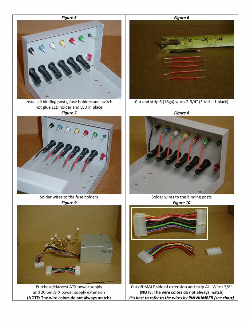
Figure 5
Install all binding posts, fuse holders and switch
hot glue LED holder and LED in place
Figure 6
Cut and strip 6 (18ga) wires 2-3/4” (5 red – 1 black)
Figure 7
Solder wires to the fuse holders
Figure 8
Solder wires to the binding posts
Figure 9
Purchase/Harvest ATX power supply
and 20 pin ATX power supply extension (NOTE: The wire colors do not always match)
Figure 10
Cut off MALE side of extension and strip ALL Wires 3/8”
(NOTE: The wire colors do not always match) it’s best to refer to the wires by PIN NUMBER (see chart)
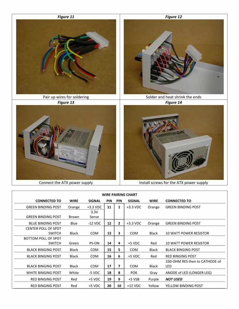
Figure 11
Pair up wires for soldering
Figure 12
Solder and heat shrink the ends
Figure 13
Connect the ATX power supply
Figure 14
Install screws for the ATX power supply
WIRE PAIRING CHART
CONNECTED TO WIRE SIGNAL PIN PIN SIGNAL WIRE CONNECTED TO
GREEN BINDING POST Orange +3.3 VDC 11 1 +3.3 VDC Orange GREEN BINDING POST
GREEN BINDING POST Brown 3.3V
Sense BLUE BINDING POST Blue -12 VDC 12 2 +3.3 VDC Orange GREEN BINDING POST
CENTER POLL OF SPDT SWITCH Black COM 13 3 COM Black 10 WATT POWER RESISTOR
BOTTOM POLL OF SPDT SWITCH Green PS-ON 14 4 +5 VDC Red 10 WATT POWER RESISTOR
BLACK BINGING POST Black COM 15 5 COM Black BLACK BINGING POST
BLACK BINGING POST Black COM 16 6 +5 VDC Red RED BINGING POST
BLACK BINGING POST Black COM 17 7 COM Black 330-OHM RES then to CATHODE of LED
WHITE BINGING POST White -5 VDC 18 8 POK Gray ANODE of LED (LONGER LEG)
RED BINGING POST Red +5 VDC 19 9 +5 VSB Purple NOT USED
RED BINGING POST Red +5 VDC 20 10 +12 VDC Yellow YELLOW BINDING POST
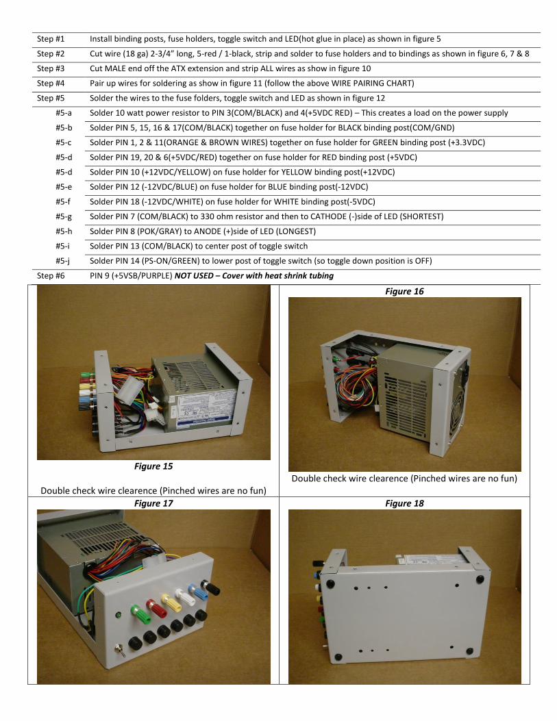
Step #1 Install binding posts, fuse holders, toggle switch and LED(hot glue in place) as shown in figure 5
Step #2 Cut wire (18 ga) 2-3/4” long, 5-red / 1-black, strip and solder to fuse holders and to bindings as shown in figure 6, 7 & 8
Step #3 Cut MALE end off the ATX extension and strip ALL wires as show in figure 10
Step #4 Pair up wires for soldering as show in figure 11 (follow the above WIRE PAIRING CHART)
Step #5 Solder the wires to the fuse folders, toggle switch and LED as shown in figure 12
#5-a Solder 10 watt power resistor to PIN 3(COM/BLACK) and 4(+5VDC RED) – This creates a load on the power supply
#5-b Solder PIN 5, 15, 16 & 17(COM/BLACK) together on fuse holder for BLACK binding post(COM/GND)
#5-c Solder PIN 1, 2 & 11(ORANGE & BROWN WIRES) together on fuse holder for GREEN binding post (+3.3VDC)
#5-d Solder PIN 19, 20 & 6(+5VDC/RED) together on fuse holder for RED binding post (+5VDC)
#5-d Solder PIN 10 (+12VDC/YELLOW) on fuse holder for YELLOW binding post(+12VDC)
#5-e Solder PIN 12 (-12VDC/BLUE) on fuse holder for BLUE binding post(-12VDC)
#5-f Solder PIN 18 (-12VDC/WHITE) on fuse holder for WHITE binding post(-5VDC)
#5-g Solder PIN 7 (COM/BLACK) to 330 ohm resistor and then to CATHODE (-)side of LED (SHORTEST)
#5-h Solder PIN 8 (POK/GRAY) to ANODE (+)side of LED (LONGEST)
#5-i Solder PIN 13 (COM/BLACK) to center post of toggle switch
#5-j Solder PIN 14 (PS-ON/GREEN) to lower post of toggle switch (so toggle down position is OFF)
Step #6 PIN 9 (+5VSB/PURPLE) NOT USED – Cover with heat shrink tubing
Figure 15
Double check wire clearence (Pinched wires are no fun)
Figure 16
Double check wire clearence (Pinched wires are no fun)
Figure 17
Figure 18
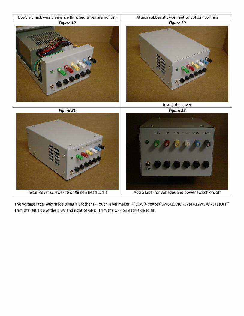
Double check wire clearence (Pinched wires are no fun) Attach rubber stick-on feet to bottom corners
Figure 19
Figure 20
Install the cover
Figure 21
Install cover screws (#6 or #8 pan head 1/4”)
Figure 22
Add a label for voltages and power switch on/off
The voltage label was made using a Brother P-Touch label maker – “3.3V(6 spaces)5V(6)12V(6)-5V(4)-12V(5)GND(2)OFF”
Trim the left side of the 3.3V and right of GND. Trim the OFF on each side to fit.


