Transfer switches atys-s_018_a ATyS S - ATyS d S Remotely operated Transfer Switching Equipment from 40 to 125 A > Genset < 90 kVA > Heating systems > Climate control > Ventilation systems > Telecommunications The solution for > Extensive power supply range > Safety and reliability > Easy integration > Simplified maintenance > ATyS d S: Dual power supply Strong points > IEC 60947-6-1 > IEC 60947-3 > GB 14048-11 Conformity to standards Function ATyS S products are 4 pole remotely operated transfer switches with positive break indication. They enable the on-load transfer of two three-phase supplies via remote volt-free contacts, from either an external automatic controller, using pulse logic, or a switch. They are intended for use in low voltage power supply systems where a brief interruption of the load supply is acceptable during transfer. Advantages Extensive power supply range The ATyS S is available in four supply versions, each with a broad range (+/-30%). The four versions are: • 12 VDC power supply. • 24/48 VDC power supply. • 230 VAC single power supply. • 2 x 230 VAC dual power supply. Safety and reliability ATyS S products use stable position technology, ensuring constant pressure on the contacts and preventing premature faults. In addition, they do not require a power supply to maintain position, thus protecting their loads from voltage fluctuations. Easy integration ATyS S products can be easily installed inside enclosures. Their design, and in particular their compact size, enables integration within most 200 mm deep enclosures. Simplified maintenance Maintenance can be carried out easily under load, with manual operation still available. The control and motorisation section can be replaced simply by removing 4 screws, with no work required on the installation cabling. ATyS d S: Dual power supply In addition to the functions offered by the ATyS S, the ATyS d S incorporates supply redundancy without the need for additional wiring. This is obtained by integrating a double supply (2 independent supplies) directly within the product. Approvals and certifications 434 General Catalogue 2017-2018
Transcript
Tran
sfer
sw
itch
es
atys
-s_0
18_a
ATyS S - ATyS d SRemotely operated Transfer Switching Equipmentfrom 40 to 125 A
> Genset < 90 kVA > Heating systems > Climate control > Ventilation systems > Telecommunications
The solution for
> Extensive power supply range
> Safety and reliability > Easy integration > Simplified maintenance > ATyS d S: Dual power supply
Strong points
> IEC 60947-6-1 > IEC 60947-3 > GB 14048-11
Conformity to standards
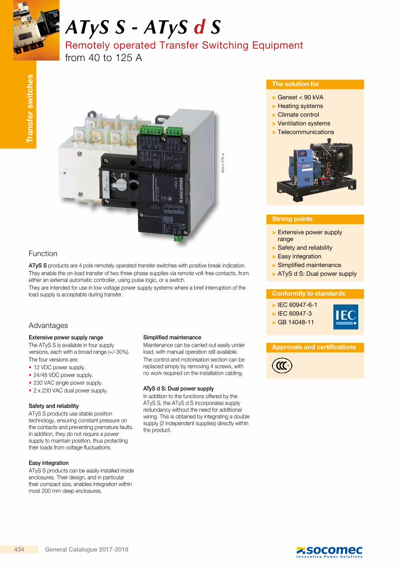
Function
ATyS S products are 4 pole remotely operated transfer switches with positive break indication.They enable the on-load transfer of two three-phase supplies via remote volt-free contacts, from either an external automatic controller, using pulse logic, or a switch.They are intended for use in low voltage power supply systems where a brief interruption of the load supply is acceptable during transfer.
Advantages
Extensive power supply rangeThe ATyS S is available in four supply versions, each with a broad range (+/-30%).The four versions are: • 12 VDC power supply. • 24/48 VDC power supply. • 230 VAC single power supply. • 2 x 230 VAC dual power supply.
Safety and reliabilityATyS S products use stable position technology, ensuring constant pressure on the contacts and preventing premature faults. In addition, they do not require a power supply to maintain position, thus protecting their loads from voltage fluctuations.
Easy integrationATyS S products can be easily installed inside enclosures. Their design, and in particular their compact size, enables integration within most 200 mm deep enclosures.
Simplified maintenanceMaintenance can be carried out easily under load, with manual operation still available.The control and motorisation section can be replaced simply by removing 4 screws, with no work required on the installation cabling.
ATyS d S: Dual power supplyIn addition to the functions offered by the ATyS S, the ATyS d S incorporates supply redundancy without the need for additional wiring. This is obtained by integrating a double supply (2 independent supplies) directly within the product.
Approvals and certifications
ATyS S - ATyS d SRemotely operated Transfer Switching Equipment
from 40 to 125 A
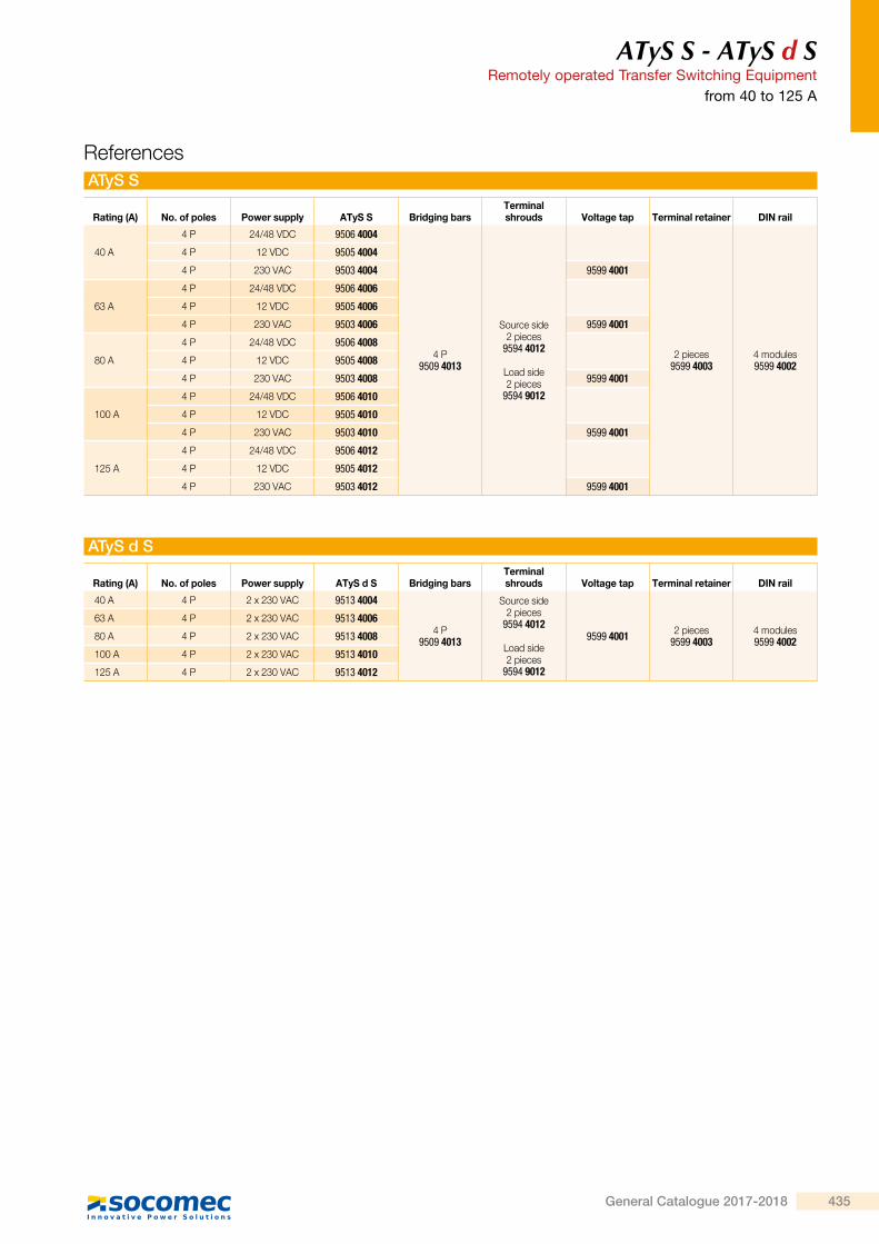
Rating (A) No. of poles Power supply ATyS S Bridging barsTerminal shrouds Voltage tap Terminal retainer DIN rail
40 A
4 P 24/48 VDC 9506 4004
4 P9509 4013
Source side2 pieces
9594 4012
Load side2 pieces
9594 9012
2 pieces9599 4003
4 modules9599 4002
4 P 12 VDC 9505 4004
4 P 230 VAC 9503 4004 9599 4001
63 A
4 P 24/48 VDC 9506 4006
4 P 12 VDC 9505 4006
4 P 230 VAC 9503 4006 9599 4001
80 A
4 P 24/48 VDC 9506 4008
4 P 12 VDC 9505 4008
4 P 230 VAC 9503 4008 9599 4001
100 A
4 P 24/48 VDC 9506 4010
4 P 12 VDC 9505 4010
4 P 230 VAC 9503 4010 9599 4001
125 A
4 P 24/48 VDC 9506 4012
4 P 12 VDC 9505 4012
4 P 230 VAC 9503 4012 9599 4001
Rating (A) No. of poles Power supply ATyS d S Bridging barsTerminal shrouds Voltage tap Terminal retainer DIN rail
40 A 4 P 2 x 230 VAC 9513 4004
4 P9509 4013
Source side2 pieces
9594 4012
Load side2 pieces
9594 9012
9599 4001 2 pieces9599 4003
4 modules9599 4002
63 A 4 P 2 x 230 VAC 9513 4006
80 A 4 P 2 x 230 VAC 9513 4008
100 A 4 P 2 x 230 VAC 9513 4010
125 A 4 P 2 x 230 VAC 9513 4012
References ATyS S
ATyS d S
434 General Catalogue 2017-2018
Tran
sfer
sw
itch
es
atys
-s_0
18_a
ATyS S - ATyS d SRemotely operated Transfer Switching Equipmentfrom 40 to 125 A
> Genset < 90 kVA > Heating systems > Climate control > Ventilation systems > Telecommunications
The solution for
> Extensive power supply range
> Safety and reliability > Easy integration > Simplified maintenance > ATyS d S: Dual power supply
Strong points
> IEC 60947-6-1 > IEC 60947-3 > GB 14048-11
Conformity to standards
Function
ATyS S products are 4 pole remotely operated transfer switches with positive break indication.They enable the on-load transfer of two three-phase supplies via remote volt-free contacts, from either an external automatic controller, using pulse logic, or a switch.They are intended for use in low voltage power supply systems where a brief interruption of the load supply is acceptable during transfer.
Advantages
Extensive power supply rangeThe ATyS S is available in four supply versions, each with a broad range (+/-30%).The four versions are: • 12 VDC power supply. • 24/48 VDC power supply. • 230 VAC single power supply. • 2 x 230 VAC dual power supply.
Safety and reliabilityATyS S products use stable position technology, ensuring constant pressure on the contacts and preventing premature faults. In addition, they do not require a power supply to maintain position, thus protecting their loads from voltage fluctuations.
Easy integrationATyS S products can be easily installed inside enclosures. Their design, and in particular their compact size, enables integration within most 200 mm deep enclosures.
Simplified maintenanceMaintenance can be carried out easily under load, with manual operation still available.The control and motorisation section can be replaced simply by removing 4 screws, with no work required on the installation cabling.
ATyS d S: Dual power supplyIn addition to the functions offered by the ATyS S, the ATyS d S incorporates supply redundancy without the need for additional wiring. This is obtained by integrating a double supply (2 independent supplies) directly within the product.
Approvals and certifications
ATyS S - ATyS d SRemotely operated Transfer Switching Equipment
from 40 to 125 A
Rating (A) No. of poles Power supply ATyS S Bridging barsTerminal shrouds Voltage tap Terminal retainer DIN rail
40 A
4 P 24/48 VDC 9506 4004
4 P9509 4013
Source side2 pieces
9594 4012
Load side2 pieces
9594 9012
2 pieces9599 4003
4 modules9599 4002
4 P 12 VDC 9505 4004
4 P 230 VAC 9503 4004 9599 4001
63 A
4 P 24/48 VDC 9506 4006
4 P 12 VDC 9505 4006
4 P 230 VAC 9503 4006 9599 4001
80 A
4 P 24/48 VDC 9506 4008
4 P 12 VDC 9505 4008
4 P 230 VAC 9503 4008 9599 4001
100 A
4 P 24/48 VDC 9506 4010
4 P 12 VDC 9505 4010
4 P 230 VAC 9503 4010 9599 4001
125 A
4 P 24/48 VDC 9506 4012
4 P 12 VDC 9505 4012
4 P 230 VAC 9503 4012 9599 4001
Rating (A) No. of poles Power supply ATyS d S Bridging barsTerminal shrouds Voltage tap Terminal retainer DIN rail
40 A 4 P 2 x 230 VAC 9513 4004
4 P9509 4013
Source side2 pieces
9594 4012
Load side2 pieces
9594 9012
9599 4001 2 pieces9599 4003
4 modules9599 4002
63 A 4 P 2 x 230 VAC 9513 4006
80 A 4 P 2 x 230 VAC 9513 4008
100 A 4 P 2 x 230 VAC 9513 4010
125 A 4 P 2 x 230 VAC 9513 4012
References ATyS S
ATyS d S
435General Catalogue 2017-2018
ATyS S - ATyS d SRemotely operated Transfer Switching Equipmentfrom 40 to 125 A
Autotransformer 400/230 VAC
UseFor applications without neutral, this autotransformer provides the 230 VAC required to power these ATyS products.
Dimensions75x80x72 mm
Rating (A) Reference
40 … 125 9599 4004
Accessories
DIN railUseThis 4-module DIN rail can be installed directly on the front of the ATyS S and can be utilised, for example, for the installation of a surge protection device.
Rating (A) Reference
40 … 125 9599 4002
Bridging barsUseFor bridging power terminals on the top or bottom side of the switch.
Rating (A) No. of poles Reference
40 … 125 4 P 9509 4013
acce
s_39
5_a_
2_ca
t
Terminal shroudsUseIP2X protection against direct contact with terminals or connecting parts.
Terminal shrouds for the source side
Rating (A) Pack Reference
40 … 125 2 pieces 9594 4012
Terminal shrouds for the load side
Rating (A) Pack Reference
40 … 125 2 pieces 9594 9012
atys
-s_0
20_a
atys
-s_0
20_a
Terminal retainer
UseThese clips have a dual function: - to prevent direct access to the power supply and control terminals and - to secure these connector terminals.
Rating (A) Pack Reference
40 … 125 2 pieces 9599 4003
atys
-s_0
21_a
Voltage tapUseEnables the required power supply for ATyS S 230 VAC and ATyS d S products to be tapped directly from the product's incoming power terminals. Can also be utilised in applications without neutral, to provide 400 VAC to the autotransformer.
Rating (A) Reference
40 … 125 9599 4001
atys
-s_0
22_a
acce
s_41
7_a_
1_ca
t
ATyS S - ATyS d SRemotely operated Transfer Switching Equipment
from 40 to 125 A
Spares Motorisation unit
Switching unit
Manual emergency operation handle
Connector kit
UseThe motorisation module of the ATyS S can be easily replaced in case of problems, even when the load is supplied.
UseReferences to be used for replacing the switching module of ATyS S products.
UseThis handle can be used on the product whether the motor unit is mounted or not.
UseThis kit, including all the connector types for the different products, can be ordered in case of loss or breaking of one connector.
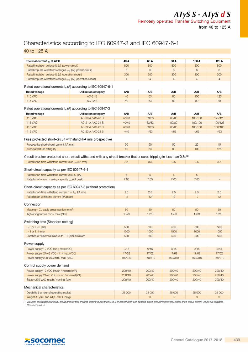
(1) Value for coordination with any circuit breaker that ensures tripping in less than 0.3s. For coordination with specific circuit-breaker references, higher short-circuit current values are available. Please consult us.
Characteristics according to IEC 60947-3 and IEC 60947-6-140 to 125 A
438 General Catalogue 2017-2018
ATyS S - ATyS d SRemotely operated Transfer Switching Equipmentfrom 40 to 125 A
(1) Value for coordination with any circuit breaker that ensures tripping in less than 0.3s. For coordination with specific circuit-breaker references, higher short-circuit current values are available. Please consult us.
Characteristics according to IEC 60947-3 and IEC 60947-6-140 to 125 A
439General Catalogue 2017-2018
ATyS S - ATyS d SRemotely operated Transfer Switching Equipmentfrom 40 to 125 A
Terminals and connections
1
4
7
2 3
1 2
317 316 315 314 04 01 24 21 14 11
65
8
201202
101102
atys
_830
_a_1
_x_c
at
ATyS d S: 2 x 230 VAC
preferred source alternate source1 : position 0 control2 : position I control3 : position II control4 : auxiliary contact, closed when the switch is in
position 05 : auxiliary contact, closed when the switch is in
position II6 : auxiliary contact, closed when the switch is in
position I7 : power supply kit I: 230 VAC (160-310 VAC)8 : power supply kit II: 230 VAC (160-310 VAC)
21
1
4
2 3
1 2
DC7
317 316 315 314 04 01 24 21 14 11
65
401402
atys
_831
_b_1
_x_c
at
ATyS S DC version
preferred source alternate source1 : position 0 control2 : position I control3 : position II control4 : auxiliary contact, closed when the switch is in position 05 : auxiliary contact, closed when the switch is in position II6 : auxiliary contact, closed when the switch is in position I7 : power supply 12 VDC (9-15 VDC) or 24 VDC / 48 VDC
(17-62 VDC) depending on the version.
21
1
4
2 3
1 2
7
317 316 315 314 04 01 24 21 14 11
65
301302
atys
_832
_a_1
_x_c
at
ATyS S: 230 VAC
preferred source alternate source1 : position 0 control2 : position I control3 : position II control4 : auxiliary contact, closed when the switch is in
position 05 : auxiliary contact, closed when the switch is in
position II6 : auxiliary contact, closed when the switch is in
position I7 : power supply kit: 230 VAC (160-310 VAC)
21
ATyS S - ATyS d SRemotely operated Transfer Switching Equipment
from 40 to 125 A
Dimensions
Cut-out dimension
Connection terminal
106
94 90.6
11
104.5
115.2 74
72
143.
5
15
113
25
7210
010
0
198
8
26.5 26.527.5
44
181 42.5
100
Ø 6.4
32
16
14
M6 125
45
37
16
14
Ø M6
atys
-s_0
24_a
_1_x
_cat
atys
-s_0
36_a
_1_x
_cat
440 General Catalogue 2017-2018
ATyS S - ATyS d SRemotely operated Transfer Switching Equipmentfrom 40 to 125 A
Terminals and connections
1
4
7
2 3
1 2
317 316 315 314 04 01 24 21 14 11
65
8
201202
101102
atys
_830
_a_1
_x_c
at
ATyS d S: 2 x 230 VAC
preferred source alternate source1 : position 0 control2 : position I control3 : position II control4 : auxiliary contact, closed when the switch is in
position 05 : auxiliary contact, closed when the switch is in
position II6 : auxiliary contact, closed when the switch is in
position I7 : power supply kit I: 230 VAC (160-310 VAC)8 : power supply kit II: 230 VAC (160-310 VAC)
21
1
4
2 3
1 2
DC7
317 316 315 314 04 01 24 21 14 11
65
401402
atys
_831
_b_1
_x_c
at
ATyS S DC version
preferred source alternate source1 : position 0 control2 : position I control3 : position II control4 : auxiliary contact, closed when the switch is in position 05 : auxiliary contact, closed when the switch is in position II6 : auxiliary contact, closed when the switch is in position I7 : power supply 12 VDC (9-15 VDC) or 24 VDC / 48 VDC
(17-62 VDC) depending on the version.
21
1
4
2 3
1 2
7
317 316 315 314 04 01 24 21 14 11
65
301302
atys
_832
_a_1
_x_c
at
ATyS S: 230 VAC
preferred source alternate source1 : position 0 control2 : position I control3 : position II control4 : auxiliary contact, closed when the switch is in
position 05 : auxiliary contact, closed when the switch is in
position II6 : auxiliary contact, closed when the switch is in
position I7 : power supply kit: 230 VAC (160-310 VAC)
21
ATyS S - ATyS d SRemotely operated Transfer Switching Equipment