ALMA International Induction Drive Loudspeakers Marshall Buck 1 , David Graebener 2, and Patrick Turnmire 3 1 Psychotechnology, Inc., Los Angeles, CA 90034 USA [email protected]2 Wisdom Audio, LLC, Carson City, NV 89706 USA [email protected]3 RedRock Acoustics, Arroyo Seco, NM 87514 USA [email protected]ABSTRACT Induction loudspeaker motors use a transformer with fixed primary and moving secondary in a static magnetic field. FEA modeling has driven this technology forward. We have built very high efficiency, mid/high compression drivers, and a linear, long stroke woofer with high output. The mid exhibits an output of over 80 acoustic watts, and a maximum 10 Watt efficiency of 45%. Reliability of induction drive is high due to the elimination of moving lead in wires. 1. INTRODUCTION Induction motors for a loudspeaker use a transformer assembly with a fixed primary and moving secondary (often a single shorted turn driving ring) immersed in a static magnetic field. Current is induced in the secondary by magnetic induction, and this current interacts with the transverse magnetic field in a conventional manner to generate an orthogonal force, which then drives the transducer diaphragm. Advantages include: • Mechanical Simplicity – No lead wires to driving ring, thus high reliability. • Single layer solid driving ring with no insulation required, further increasing reliability. • Parametric Flexibility – Impedance can be easily changed over a wide range by varying the wire size and number of turns in the primary. • Very high BL can be achieved, as well as very linear BL vs. X, and L vs. X. Design tools utilized – Finite Element Analysis (FEA) for magnetic and thermal optimization. We used a multiphysics FEA to optimize electromagnetics coupled with physics to model forces. We also utilized FEA to model diaphragm modes and simulate frequency response. Neodymium magnets are an integral element in these designs. In these realizations, a powdered metal pot surrounds the magnetic path to provide a high permeability flux path for both static and audio frequency force lines. Induction drive audio transducers can be designed to produce very high efficiency, high output mid/high devices. In another configuration a very linear, long stroke woofer with high output is realizable. Measurements will be provided on prototypes of both types of devices. 1.1. History of Induction Drive Transducers Induction drive audio transducers are not new. Nyman filed a patent for one used as a telephone receiver in 1923 ( Figure 1).
Transcript
ALMA International
Induction Drive Loudspeakers Marshall Buck1, David Graebener2, and Patrick Turnmire3
1 Psychotechnology, Inc., Los Angeles, CA 90034 USA [email protected]
Induction loudspeaker motors use a transformer with fixed primary and moving secondary in a static magnetic field. FEA modeling has driven this technology forward. We have built very high efficiency, mid/high compression drivers, and a linear, long stroke woofer with high output. The mid exhibits an output of over 80 acoustic watts, and a maximum 10 Watt efficiency of 45%. Reliability of induction drive is high due to the elimination of moving lead in wires.
1. INTRODUCTION
Induction motors for a loudspeaker use a transformer assembly with a fixed primary and moving secondary (often a single shorted turn driving ring) immersed in a static magnetic field. Current is induced in the secondary by magnetic induction, and this current interacts with the transverse magnetic field in a conventional manner to generate an orthogonal force, which then drives the transducer diaphragm. Advantages include:
• Mechanical Simplicity – No lead wires to driving ring, thus high reliability.
• Single layer solid driving ring with no insulation required, further increasing reliability.
• Parametric Flexibility – Impedance can be easily changed over a wide range by varying the wire size and number of turns in the primary.
• Very high BL can be achieved, as well as very linear BL vs. X, and L vs. X.
Design tools utilized – Finite Element Analysis (FEA) for magnetic and thermal optimization. We used a multiphysics FEA to optimize electromagnetics coupled with physics to model forces. We also utilized FEA to
model diaphragm modes and simulate frequency response. Neodymium magnets are an integral element in these designs. In these realizations, a powdered metal pot surrounds the magnetic path to provide a high permeability flux path for both static and audio frequency force lines. Induction drive audio transducers can be designed to produce very high efficiency, high output mid/high devices. In another configuration a very linear, long stroke woofer with high output is realizable. Measurements will be provided on prototypes of both types of devices.
1.1. History of Induction Drive Transducers
Induction drive audio transducers are not new. Nyman filed a patent for one used as a telephone receiver in 1923 ( Figure 1).
Buck, et. al. Induction Drive Loudspeakers
ALMA International Las Vegas, January 6, 2010 Page 2 of 12
Figure 1 Induction Drive Telephone Receiver
Induction drive transducers have been designed as tweeters in coaxial placement to cone woofers, using a conductive dome as a shorted turn secondary, with the woofer voice coil as the primary. Efficiency has generally been low. A patent by Elieli shows a coaxial assembly with a horn loaded induction drive tweeter (Figure 2).
Figure 2 above: Elieli patent drawing for induction drive tweeter in a coaxial configuration.
The horn loading improves the response accuracy and the efficiency so the tweeter level matches the woofer.
Figure 3 above shows Klipsch designs from 1991, with variations on primary coil locations.
Figure 4 above shows a proprietary Wisdom Audio design (2008) using a powdered iron pot structure to increase flux linkage while reducing eddy current losses.
Buck, et. al. Induction Drive Loudspeakers
ALMA International Las Vegas, January 6, 2010 Page 3 of 12
2. INDUCTION DRIVE #1 18 INCH WOOFER
Figure 5 above shows Solidworks cutaway of induction motor The working principles of the induction motor as applied in the new designs was as follows:
Figure 6 above diagrams motor function
The force is generated following the right hand rule of three orthogonal vectors.
Using the design principles outlined above, an 18 inch woofer was designed and tested.
Figure 7 above shows 18 inch woofer motor structure. The yellow painted rings are the powdered iron pot elements, used to close the flux loops around the transformer primary/secondary assembly.
2.1. Measurements of the completed prototype 18 inch woofer
Figure 8 above is the free air impedance of the 18 incher. Below is a table of the Thiele/Small parameters of the 18, as calculated with MLSSA SPO. Monster 18 T/S "Method: Mass-loaded (399.000 grams)" "DCR mode: Measure (-0.12 ohms)" "Area (Sd): 1164.16 sq cm" "Series resistance: 75.00 ohms" "Stimulus level: 1.00 volts"
Buck, et. al. Induction Drive Loudspeakers
ALMA International Las Vegas, January 6, 2010 Page 4 of 12
"SPLref reference impedance: 8 ohms" "Large units (volume = liters, mass = grams)" 5.213 "RMSE-free Ohms" 40.935 "Fs Hz" 1.325 "Re Ohms[dc]" 24.019 "Res Ohms" 2.987 "Qms " 0.165 "Qes " 0.156 "Qts " 2.781 "L1 mH" 3.490 "L2 mH" 12.225 "R2 Ohms" 4.244 "RMSE-load Ohms" 58.214 "Vas(Sd) liters" 494.278 "Mms grams" 30.583 "Cms uM/Newton" 31.971 "Bl Tesla-M" 103.483 "SPLref(Sd) dB " 0.258 "Rub-index " Klippel analysis revealed that this driver had very linear motor parameters as a function of displacement.
KLIPPEL
0
5
10
15
20
25
30
35
-25 -20 -15 -10 -5 0 5 10 15 20 25
Force factor Bl vs. displacement X
Bl
[N/A
]
Displacement X [mm]
Bl(X)
Figure 9 above shows a very linear BL vs x within a 30 mm range.
KLIPPEL
0.0
0.1
0.2
0.3
0.4
0.5
0.6
0.7
0.8
0.9
1.0
-25 -20 -15 -10 -5 0 5 10 15 20 25
Voice coil inductance Le vs. displacement X
Le [
mH
]
Displacement X [mm]
Le(X)
Figure 10 above shows a very linear inductance vs. x
Figure 11 above shows a not very linear compliance vs. x .
2.2. Lessons Learned from 18 in Induction Motor Woofer
The 18 inch woofer suffered shipping damage on its last trip, so we did not succeed in testing it fully, in an enclosure.
Buck, et. al. Induction Drive Loudspeakers
ALMA International Las Vegas, January 6, 2010 Page 5 of 12
It did show that the induction motor created high BL and linear excursion.
It was decided to exploit the high BL feature of an induction motor by designing a compression driver. There is no upper limit for BL in a compression driver on a horn – performance keeps improving as the motor strength increases. Work had been done recently on an acoustic hailing device for military shipboard use, and a high output voice range driver was targeted. The goal was to produce 500 acoustic watts, thus projecting 98 dB SPL at 500 Meters on a horn with 17 dB directivity index (DI), a 30 x 30 degree coverage. Efficiency goal was 75%, so 666 Watts input would be required to produce the target SPL.
3.1. Modeling and Measurements of Prototype #2
A number of FEA simulations were performed, and a 4 inch diameter secondary driving a 6 inch diameter concave diaphragm was chosen, The 4 inch diameter motor was designed to have a BL of 42 Finecone simulations were performed on various Ti 6 inch diameter domes, and we selected the 5 inch radius version in 6 mil thickness.
Figure 12 above shows the dome simulation with a peak at 3.5 kHz.
Figure 13 above shows a photo of the CID gap with primary and PM segments.
Figure 14 above shows a photo of the CID dome, frame, and secondary
Buck, et. al. Induction Drive Loudspeakers
ALMA International Las Vegas, January 6, 2010 Page 6 of 12
3.1.1. Equivalent Circuit Modeling
Rp Xeq
Xm Rm
Rs XsN1 : 1 BL : 1 Mms Rms Cms
AC u
Figure 15 above is the equivalent circuit for the induction motor impedance. The first 4 terms are from standard transformer theory with terms modified to reflect application to an induction speaker. These terms are also common for use with induction machines in general. Xm Magnetizing inductance. (Permeability of
the gap area between primary and secondary)
Rm Hysteresis losses in the plates, pole Xeq Series Inductance. (Flux Leakage or
coupling factor “K”) Rp Resistance of the primary Rs Resistance of the secondary Xs Inductance of the secondary Rms Mechanical resistance of the system Cms Compliance of the total suspension Mms Mass of the moving parts including air
load N1 Turns in the primary
Figure 16 above is a comparison graph of LSPCad simulated vs. measured impedance of the CID.
A major difference between the induction motor Z and a standard driver is the drop in impedance at low frequencies, which is accurately modeled by the equivalent circuit proposed above. Another way to view this is that the impedance above resonance is higher than in a standard driver.
Figure 17 above shows an LTSpice equivalent circuit model for the induction mid. Running this simulation resulted in graphs showing frequency response, impedance and displacement.
Figure 18 above shows the frequency response of the CID on a plane wave tube. Comparing Figure 18 with the LTSpice SPL, Figure 19, there a good correlation with the major characteristics.
Buck, et. al. Induction Drive Loudspeakers
ALMA International Las Vegas, January 6, 2010 Page 7 of 12
Figure 19 above shows an LTSpice model plot of SPL.
Figure 20 above shows an LTSpice model plot of impedance for the induction mid.
KLIPPEL
2.5
5.0
7.5
10.0
12.5
2 5 10 20 50 100 200 500 1k 2k 5k 10k
Magnitude of transfer function H(f)H(f)= Voltage Speaker 1 / Current Speaker 1
[Ohm]
Frequency [Hz]
Magnitude
Figure 21 above shows the Klippel analyzer measured impedance of the CID. It correlates well with the LTSpice simulation.
Figure 22 above shows the LTSpice predicted displacement
Figure 23 above shows the Klippel measured displacement with 0.5 volt drive. The measured displacement correlates well with the LTSpice simulation.
3.1.2. Finite Element (FEA) Modeling
Figure 24 above shows a SolidWorks image of the CIM motor.
Buck, et. al. Induction Drive Loudspeakers
ALMA International Las Vegas, January 6, 2010 Page 8 of 12
FEMM Electromagnetic Modeling
Figure 25 above shows current density at 1 kHz in CID
Figure 26 above shows flux density at DC in CID
FEA 3D power analysis: One solid PM ring
Figure 27 above shows the heat in the PM using a solid ring magnet. AC time=0, Eddy current (410 Amp, peak) induced in the PM. (1 solid ring). Primary current (intensity by color mapping, direction given by arrows) is 1000AT at 300 Hz. Average power dissipated in PM is 221 W
Figure 28 above shows the heat in the secondary using a solid ring PM. AC time=0, Peak Current induced in the secondary (590 Amp). Primary current (intensity by color mapping, direction given by arrows) is 1000AT at 300 Hz. Average Power induced is 321.5 Watts.
Buck, et. al. Induction Drive Loudspeakers
ALMA International Las Vegas, January 6, 2010 Page 9 of 12
FEA 3D power analysis: Six (6) 60-degree PM segments
Figure 29 above shows the heat in the segmented PM.
AC time=90, Eddy current induced (peak) in the PM. (6 blocks of 60 degrees each). Primary current (intensity by color mapping, direction given by arrows) is 1000AT at 300 Hz.
Only .14 W dissipated in PM’s.
Note: Main contribution is secondary coil magnetic field. Therefore a six segment magnet was designed.
Figure 30 above shows the heat in the secondary, with the segmented PM.
FEA Thermal Analysis Assuming 170 Watt dissipated in the primary coil and a convection coefficient of 6.3 W/(m**2.K)
Figure 31 above shows transient rise in primary coil temperature. Primary temperature reached 150 C in 60 seconds. AC time=0, Current induced in the secondary (998 Amps). Primary current (intensity by color mapping, direction given by arrows) is 1000AT at 300 Hz. Average Power induced is 368 Watts.
Figure 32 above shows transient rise in secondary temperature Secondary temperature reached 280 C in 60 seconds.
Buck, et. al. Induction Drive Loudspeakers
ALMA International Las Vegas, January 6, 2010 Page 10 of 12
These temperature profiles show that the highest temperatures will occur in the secondary. Ferrofluid can be useful in this application.
Figure 33 above shows the heat in the sectioned secondary at the five second point of the transient. Assumptions: 380 Amps generated in secondary for 53 Watts dissipated at 300Hz Secondary physical properties are: K = 6.02 W/in.K Density = .044 Kg/in**3 C = 366 J/kg.K Convection coefficient on surface of coil is 15 W/m**2.K (.01W/in**2.K). Ambient temperature is 25 C
Figure 34 above shows induced current density in secondary at 300 Hz.
Figure 35 above shows the simulated steady state temperature in the CID motor.
Buck, et. al. Induction Drive Loudspeakers
ALMA International Las Vegas, January 6, 2010 Page 11 of 12
4. MAXIMUM OUTPUT AND EFFICIENCY TESTS
A Smith theory phasing plug was designed and constructed using stereo lithography apparatus.
The Bob Smith design targets selected crossmodes for cancellation. The first three modes were calculated using Bessel solutions to be 2000, 3661 and 5307 Hz. As the third mode was out of band, we chose the first two modes for cancellation, requiring a two slot plug. An Excel spreadsheet was written to calculate the required slot dimensions using GoalSeek to achieve the desired entrance and exit areas, to realize a 5:1 compression ratio. Calculations showed that the compression ratio for maximum efficiency was 50.9, but this would create too much distortion for high quality music reproduction, so the lower ratio was chosen. A 50:1 plug could be designed for speech only work.
Figure 36 above shows the phase plug entrance slots.
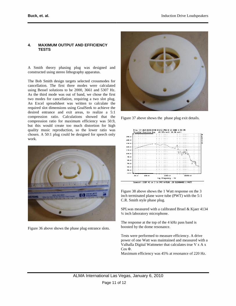
Figure 37 above shows the phase plug exit details.
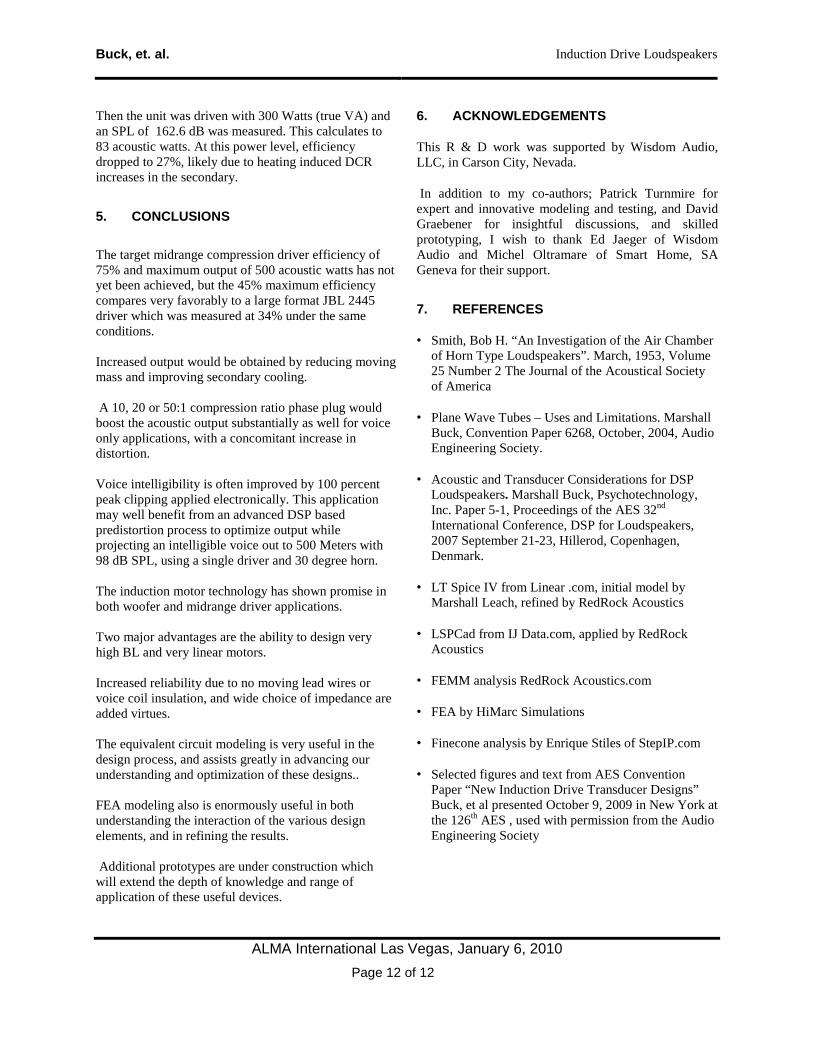
Figure 38 above shows the 1 Watt response on the 3 inch terminated plane wave tube (PWT) with the 5:1 C.R. Smith style phase plug. SPLwas measured with a calibrated Bruel & Kjaer 4134 ¼ inch laboratory microphone. The response at the top of the 4 kHz pass band is boosted by the dome resonance. Tests were performed to measure efficiency. A drive power of one Watt was maintained and measured with a Valhalla Digital Wattmeter that calculates true V x A x Cos Φ. Maximum efficiency was 45% at resonance of 220 Hz.
Buck, et. al. Induction Drive Loudspeakers
ALMA International Las Vegas, January 6, 2010 Page 12 of 12
Then the unit was driven with 300 Watts (true VA) and an SPL of 162.6 dB was measured. This calculates to 83 acoustic watts. At this power level, efficiency dropped to 27%, likely due to heating induced DCR increases in the secondary.
5. CONCLUSIONS
The target midrange compression driver efficiency of 75% and maximum output of 500 acoustic watts has not yet been achieved, but the 45% maximum efficiency compares very favorably to a large format JBL 2445 driver which was measured at 34% under the same conditions. Increased output would be obtained by reducing moving mass and improving secondary cooling. A 10, 20 or 50:1 compression ratio phase plug would boost the acoustic output substantially as well for voice only applications, with a concomitant increase in distortion. Voice intelligibility is often improved by 100 percent peak clipping applied electronically. This application may well benefit from an advanced DSP based predistortion process to optimize output while projecting an intelligible voice out to 500 Meters with 98 dB SPL, using a single driver and 30 degree horn. The induction motor technology has shown promise in both woofer and midrange driver applications. Two major advantages are the ability to design very high BL and very linear motors. Increased reliability due to no moving lead wires or voice coil insulation, and wide choice of impedance are added virtues. The equivalent circuit modeling is very useful in the design process, and assists greatly in advancing our understanding and optimization of these designs.. FEA modeling also is enormously useful in both understanding the interaction of the various design elements, and in refining the results. Additional prototypes are under construction which will extend the depth of knowledge and range of application of these useful devices.
6. ACKNOWLEDGEMENTS
This R & D work was supported by Wisdom Audio, LLC, in Carson City, Nevada.
In addition to my co-authors; Patrick Turnmire for expert and innovative modeling and testing, and David Graebener for insightful discussions, and skilled prototyping, I wish to thank Ed Jaeger of Wisdom Audio and Michel Oltramare of Smart Home, SA Geneva for their support.
7. REFERENCES
• Smith, Bob H. “An Investigation of the Air Chamber of Horn Type Loudspeakers”. March, 1953, Volume 25 Number 2 The Journal of the Acoustical Society of America
• Plane Wave Tubes – Uses and Limitations. Marshall Buck, Convention Paper 6268, October, 2004, Audio Engineering Society.
• Acoustic and Transducer Considerations for DSP Loudspeakers. Marshall Buck, Psychotechnology, Inc. Paper 5-1, Proceedings of the AES 32nd International Conference, DSP for Loudspeakers, 2007 September 21-23, Hillerod, Copenhagen, Denmark.
• LT Spice IV from Linear .com, initial model by Marshall Leach, refined by RedRock Acoustics
• LSPCad from IJ Data.com, applied by RedRock Acoustics
• FEMM analysis RedRock Acoustics.com
• FEA by HiMarc Simulations
• Finecone analysis by Enrique Stiles of StepIP.com
• Selected figures and text from AES Convention Paper “New Induction Drive Transducer Designs” Buck, et al presented October 9, 2009 in New York at the 126th AES , used with permission from the Audio Engineering Society