Electrical and Computer Engineering, Cleveland State University Audio File Transmission using GNU RADIO and USRP EEC 687 - Mobile Computing (Fall 2016) Final Project Report Raag Kharadi CSUID: 2644321 Harshil Mehta CSUID: 2643874
Transcript
Electrical and Computer Engineering, Cleveland State University
Audio File Transmission using GNU RADIO and USRP
EEC 687 - Mobile Computing (Fall 2016)
Final Project Report
Raag Kharadi CSUID: 2644321
Harshil Mehta CSUID: 2643874
Electrical and Computer Engineering, Cleveland State University
Introduction
In radio engineering radio engineers were facing problem related to chip computing power so they
had to think again to redesign of radio receivers. Since, from many decades’ hardware for radio
transceiver consist of signal were down converted to intermediate frequency then filtered and then
demodulated after converting to baseband signal. After few years around 1980’s digital signal
processor leads to development of digital transceivers. This kind of digital transceivers requires
hardware for just for limiting frequency to narrow band frequency and then ADC and other portion of architecture consist of software interface so this kind of transceivers leads to so-called Software
Define Radios(SDR’s). In SDR there is general purpose processors and other devices which perform
signal processing are integrated in FPGA.
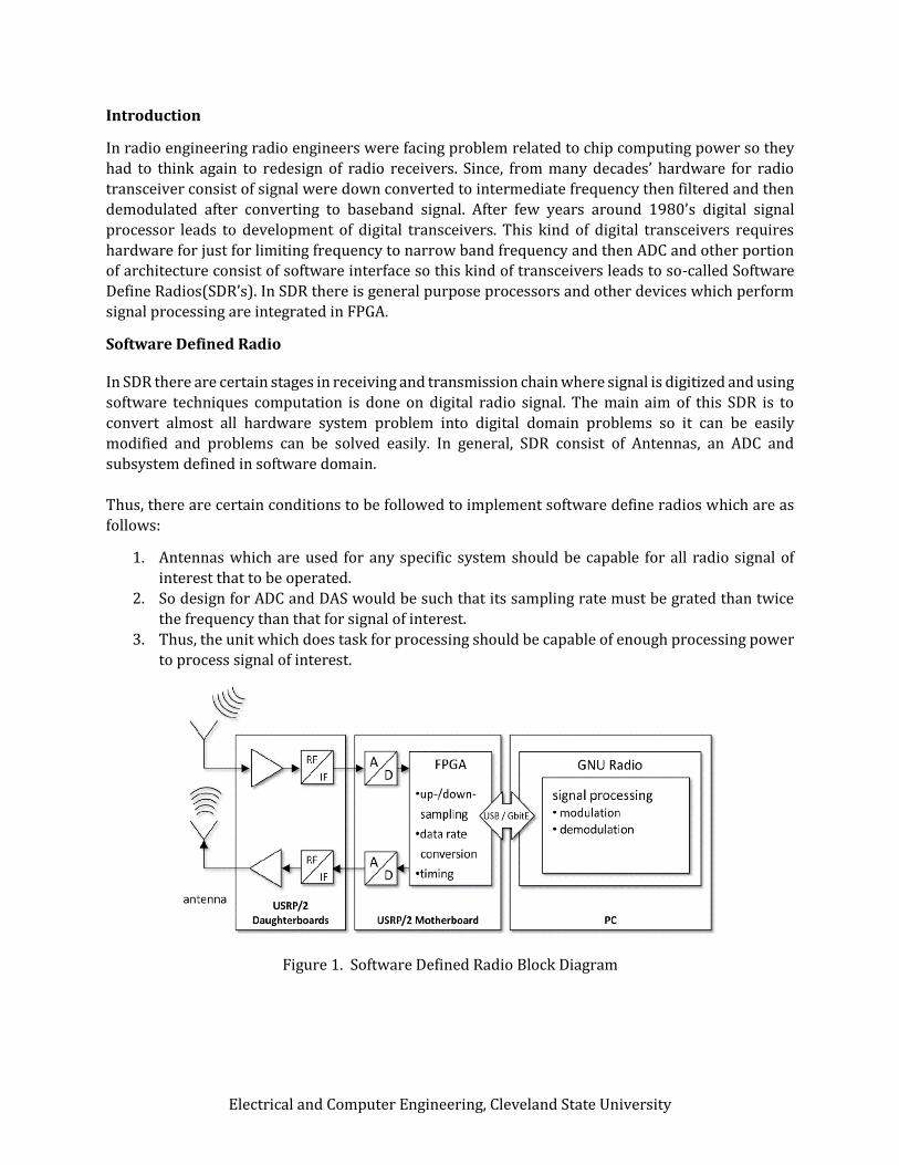
Software Defined Radio In SDR there are certain stages in receiving and transmission chain where signal is digitized and using
software techniques computation is done on digital radio signal. The main aim of this SDR is to
convert almost all hardware system problem into digital domain problems so it can be easily
modified and problems can be solved easily. In general, SDR consist of Antennas, an ADC and
subsystem defined in software domain.
Thus, there are certain conditions to be followed to implement software define radios which are as
follows:
1. Antennas which are used for any specific system should be capable for all radio signal of
interest that to be operated.
2. So design for ADC and DAS would be such that its sampling rate must be grated than twice
the frequency than that for signal of interest.
3. Thus, the unit which does task for processing should be capable of enough processing power
to process signal of interest.
Figure 1. Software Defined Radio Block Diagram
Electrical and Computer Engineering, Cleveland State University
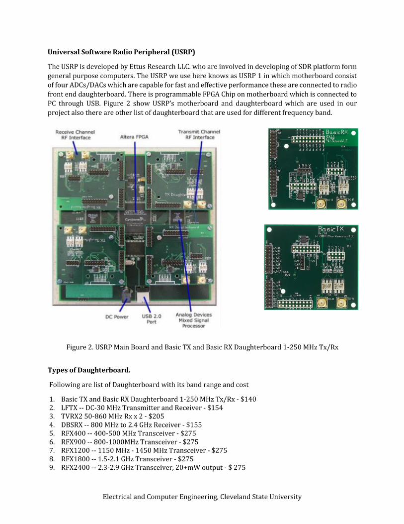
Universal Software Radio Peripheral (USRP)
The USRP is developed by Ettus Research LLC. who are involved in developing of SDR platform form
general purpose computers. The USRP we use here knows as USRP 1 in which motherboard consist
of four ADCs/DACs which are capable for fast and effective performance these are connected to radio
front end daughterboard. There is programmable FPGA Chip on motherboard which is connected to
PC through USB. Figure 2 show USRP’s motherboard and daughterboard which are used in our
project also there are other list of daughterboard that are used for different frequency band.
Figure 2. USRP Main Board and Basic TX and Basic RX Daughterboard 1-250 MHz Tx/Rx
Types of Daughterboard.
Following are list of Daughterboard with its band range and cost
Electrical and Computer Engineering, Cleveland State University
GNU Radio
GNU radio provide software environment for developing and which is open source and free of cost software and also has inbuilt signal processing blocks for implementation of software radios. For creating SDR it provides less cost RF hardware and it also provides stimulation like user interface which does not required physical hardware. It is widely used in real radio systems and for research related work for wireless communication.
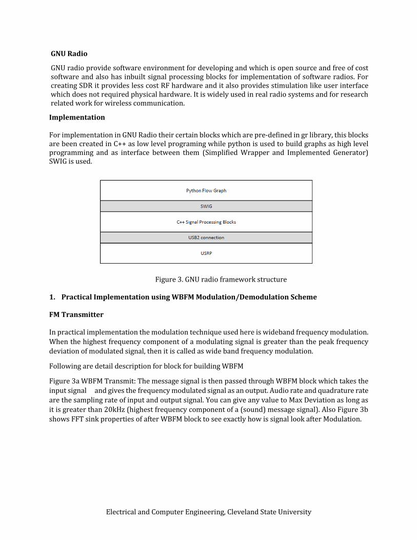
Implementation For implementation in GNU Radio their certain blocks which are pre-defined in gr library, this blocks are been created in C++ as low level programing while python is used to build graphs as high level programming and as interface between them (Simplified Wrapper and Implemented Generator) SWIG is used.
Figure 3. GNU radio framework structure
1. Practical Implementation using WBFM Modulation/Demodulation Scheme FM Transmitter In practical implementation the modulation technique used here is wideband frequency modulation.
When the highest frequency component of a modulating signal is greater than the peak frequency
deviation of modulated signal, then it is called as wide band frequency modulation.
Following are detail description for block for building WBFM
Figure 3a WBFM Transmit: The message signal is then passed through WBFM block which takes the
input signal and gives the frequency modulated signal as an output. Audio rate and quadrature rate
are the sampling rate of input and output signal. You can give any value to Max Deviation as long as
it is greater than 20kHz (highest frequency component of a (sound) message signal). Also Figure 3b
shows FFT sink properties of after WBFM block to see exactly how is signal look after Modulation.
Electrical and Computer Engineering, Cleveland State University
(A)
(B) (C)
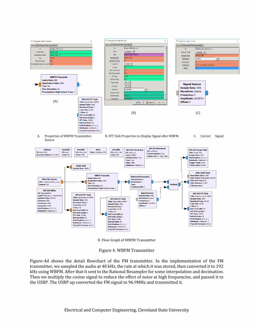
A. Properties of WBFM Transmitter. B. FFT Sink Properties to Display Signal after WBFM. C. Carrier Signal Source
D. Flow Graph of WBFM Transmitter
Figure 4. WBFM Transmitter
Figure-4d shows the detail flowchart of the FM transmitter. In the implementation of the FM transmitter, we sampled the audio at 48 kHz, the rate at which it was stored, then converted it to 192 kHz using WBFM. After that it sent to the Rational Resampler for some interpolation and decimation. Then we multiply the cosine signal to reduce the effect of noise at high frequencies, and passed it to the USRP. The USRP up converted the FM signal to 96.9MHz and transmitted it.
Electrical and Computer Engineering, Cleveland State University
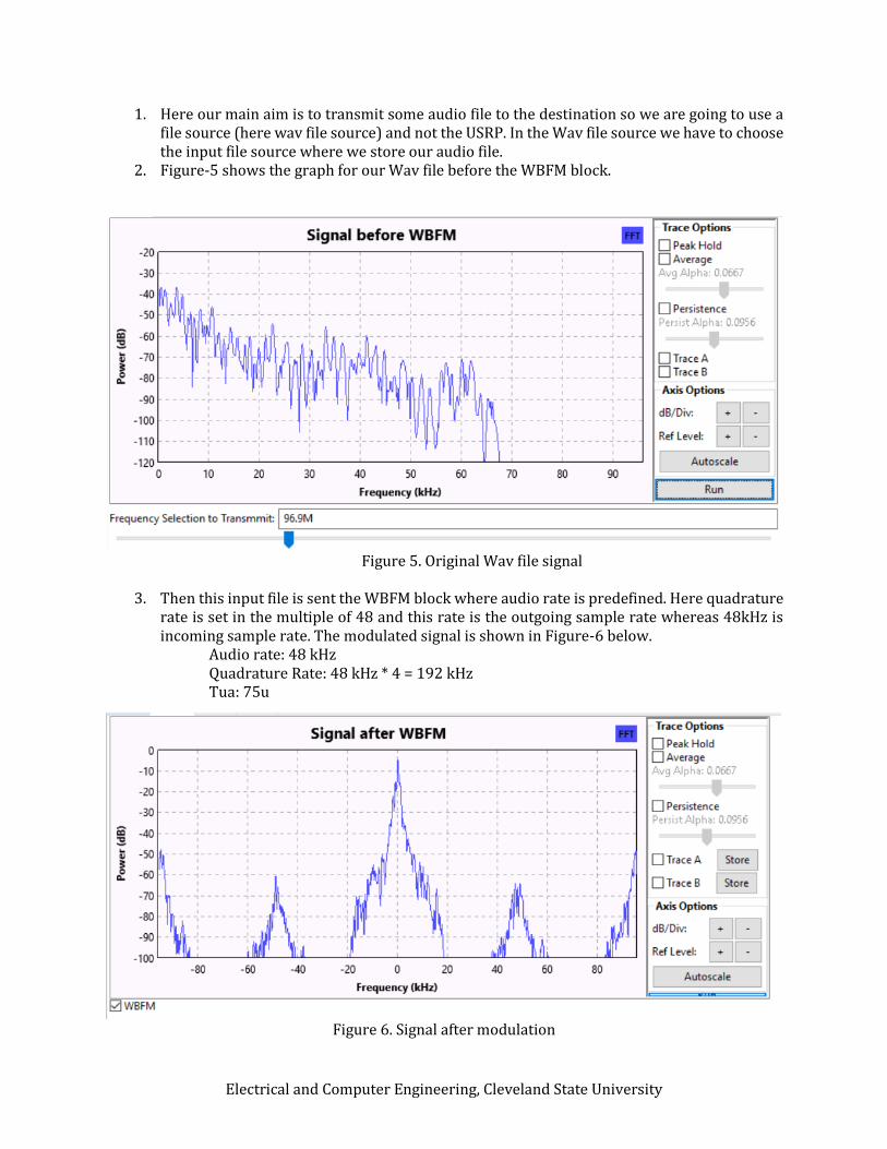
1. Here our main aim is to transmit some audio file to the destination so we are going to use a file source (here wav file source) and not the USRP. In the Wav file source we have to choose the input file source where we store our audio file.
2. Figure-5 shows the graph for our Wav file before the WBFM block.
Figure 5. Original Wav file signal
3. Then this input file is sent the WBFM block where audio rate is predefined. Here quadrature rate is set in the multiple of 48 and this rate is the outgoing sample rate whereas 48kHz is incoming sample rate. The modulated signal is shown in Figure-6 below.
Electrical and Computer Engineering, Cleveland State University
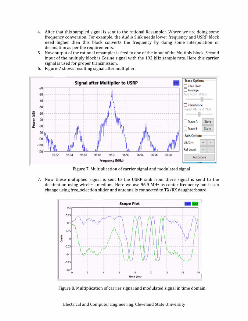
4. After that this sampled signal is sent to the rational Resampler. Where we are doing some frequency conversion. For example, the Audio Sink needs lower frequency and USRP block need higher then this block converts the frequency by doing some interpolation or decimation as per the requirements.
5. Now output of the rational resampler is feed to one of the input of the Multiply block. Second input of the multiply block is Cosine signal with the 192 kHz sample rate. Here this carrier signal is used for proper transmission.
6. Figure-7 shows resulting signal after multiplier.
Figure 7. Multiplication of carrier signal and modulated signal
7. Now these multiplied signal is sent to the USRP sink from there signal is send to the
destination using wireless medium. Here we use 96.9 MHz as center frequency but it can change using freq_selection slider and antenna is connected to TX/RX daughterboard.
Figure 8. Multiplication of carrier signal and modulated signal in time domain
Electrical and Computer Engineering, Cleveland State University
FM Receiver
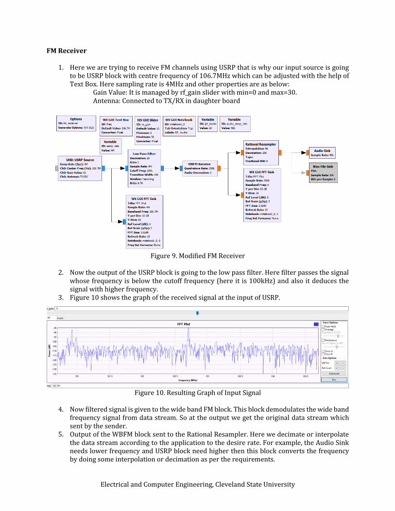
1. Here we are trying to receive FM channels using USRP that is why our input source is going to be USRP block with centre frequency of 106.7MHz which can be adjusted with the help of Text Box. Here sampling rate is 4MHz and other properties are as below:
Gain Value: It is managed by rf_gain slider with min=0 and max=30. Antenna: Connected to TX/RX in daughter board
Figure 9. Modified FM Receiver
2. Now the output of the USRP block is going to the low pass filter. Here filter passes the signal
whose frequency is below the cutoff frequency (here it is 100kHz) and also it deduces the signal with higher frequency.
3. Figure 10 shows the graph of the received signal at the input of USRP.
Figure 10. Resulting Graph of Input Signal
4. Now filtered signal is given to the wide band FM block. This block demodulates the wide band frequency signal from data stream. So at the output we get the original data stream which sent by the sender.
5. Output of the WBFM block sent to the Rational Resampler. Here we decimate or interpolate the data stream according to the application to the desire rate. For example, the Audio Sink needs lower frequency and USRP block need higher then this block converts the frequency by doing some interpolation or decimation as per the requirements.
Electrical and Computer Engineering, Cleveland State University
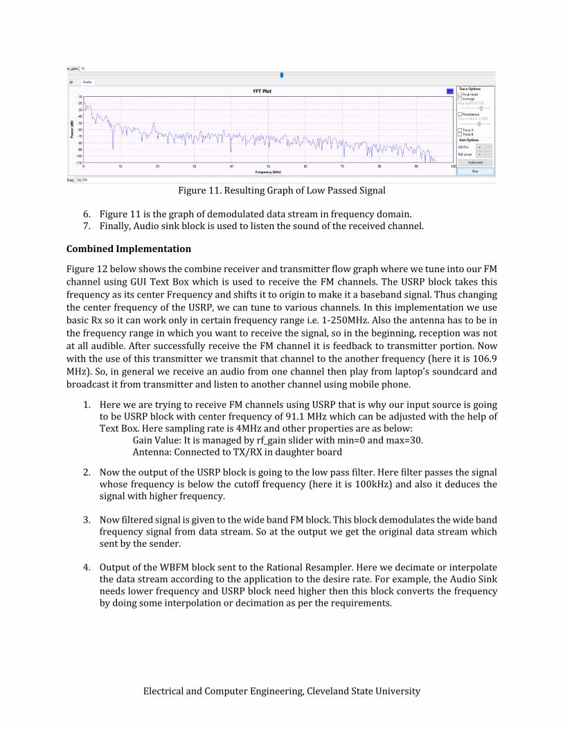
Figure 11. Resulting Graph of Low Passed Signal
6. Figure 11 is the graph of demodulated data stream in frequency domain. 7. Finally, Audio sink block is used to listen the sound of the received channel.
Combined Implementation
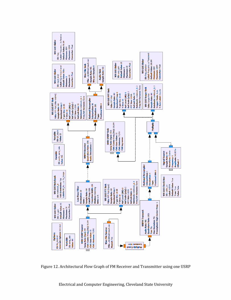
Figure 12 below shows the combine receiver and transmitter flow graph where we tune into our FM
channel using GUI Text Box which is used to receive the FM channels. The USRP block takes this
frequency as its center Frequency and shifts it to origin to make it a baseband signal. Thus changing
the center frequency of the USRP, we can tune to various channels. In this implementation we use
basic Rx so it can work only in certain frequency range i.e. 1-250MHz. Also the antenna has to be in
the frequency range in which you want to receive the signal, so in the beginning, reception was not
at all audible. After successfully receive the FM channel it is feedback to transmitter portion. Now
with the use of this transmitter we transmit that channel to the another frequency (here it is 106.9
MHz). So, in general we receive an audio from one channel then play from laptop’s soundcard and
broadcast it from transmitter and listen to another channel using mobile phone.
1. Here we are trying to receive FM channels using USRP that is why our input source is going to be USRP block with center frequency of 91.1 MHz which can be adjusted with the help of Text Box. Here sampling rate is 4MHz and other properties are as below:
Gain Value: It is managed by rf_gain slider with min=0 and max=30. Antenna: Connected to TX/RX in daughter board
2. Now the output of the USRP block is going to the low pass filter. Here filter passes the signal whose frequency is below the cutoff frequency (here it is 100kHz) and also it deduces the signal with higher frequency.
3. Now filtered signal is given to the wide band FM block. This block demodulates the wide band
frequency signal from data stream. So at the output we get the original data stream which sent by the sender.
4. Output of the WBFM block sent to the Rational Resampler. Here we decimate or interpolate
the data stream according to the application to the desire rate. For example, the Audio Sink needs lower frequency and USRP block need higher then this block converts the frequency by doing some interpolation or decimation as per the requirements.
Electrical and Computer Engineering, Cleveland State University
Figure 12. Architectural Flow Graph of FM Receiver and Transmitter using one USRP
Electrical and Computer Engineering, Cleveland State University
5. Finally, Audio sink block is used to listen the sound of the received channel. Now as per our flow graph we are going to feed this back to transmitter for broadcasting. That’s why it is used as input to the WBFM block.
6. Here in WBFM block quadrature rate is set in the multiple of 96 (i.e. 192 kHz) and this rate is
7. After that this sampled signal is sent to the rational Resampler. Where we are doing some
frequency conversion again.
8. Now output of the rational resampler is feed to one of the input of the Multiply block. Second input of the multiply block is Cosine signal with the 192 kHz sample rate. Here this carrier signal is used for proper transmission.
9. Now these multiplied signal is sent to the USRP sink from there signal is send to the destination using wireless medium. Here we use 106.9 MHz as center frequency but it can change and antenna is connected to TX/RX on daughterboard.
2. Implementation using GMSK Modulation/Demodulation Scheme
What is GMSK?
Gaussian Minimum Shift Keying (GMSK)
When we use half sinusoidal pulse instead of rectangular pulse then it creates the MSK (Minimum
Shift Keying) signal. But when we use Gaussian Pulse shape rather than rectangular pulse then that
type of modulation scheme is known as Gaussian Minimum Shift Keying (GMSK). Many studies states
that GMSK digital modulation technique is revised adaptation of Minimum Shift Keying (MSK) in
terms of bandwidth and spectral efficiency. In addition to that, GMSK has comparatively curtail side
lobe level than the rectangular pulse and its main lobe is also confined than the QPSK and MSK. We
can consider GMSK not only frequency modulation scheme but also we can view GMSK as phase
modulation. Although changing of phase is restricted because of Gaussian response but advance or
delay of 90˚ over bit period is not limited so beat shaping depends on Bandwidth Time Product (BT).
Here in GMSK system bandwidth is totally depends on multiplication of filter bandwidth (before
modulation) B and bit period T. Because of narrow bandwidth, GMSK suffers from Inter Symbol
Interference (ISI) which decrease the signal power.
GMSK Modulation
Frequency Shift Keyed Modulation and Quadrature Phase shift keyed Modulation are the two main
methods for generating the GMSK.
Electrical and Computer Engineering, Cleveland State University
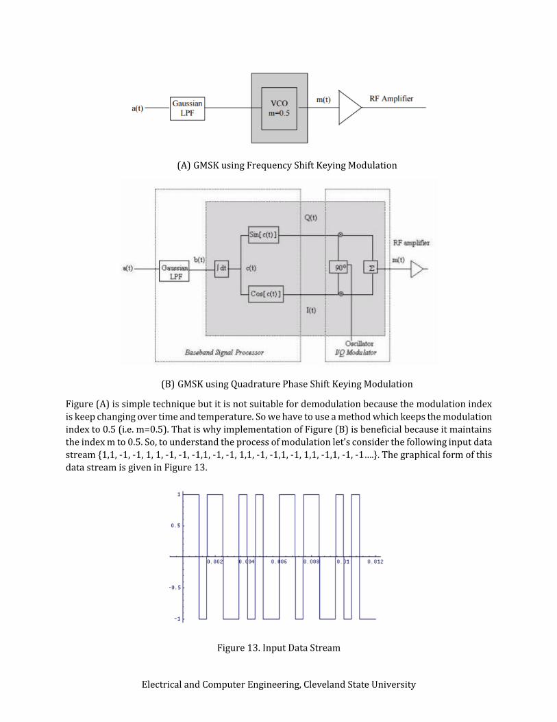
(A) GMSK using Frequency Shift Keying Modulation
(B) GMSK using Quadrature Phase Shift Keying Modulation
Figure (A) is simple technique but it is not suitable for demodulation because the modulation index
is keep changing over time and temperature. So we have to use a method which keeps the modulation
index to 0.5 (i.e. m=0.5). That is why implementation of Figure (B) is beneficial because it maintains
the index m to 0.5. So, to understand the process of modulation let’s consider the following input data
stream {1,1, -1, -1, 1, 1, -1, -1, -1,1, -1, -1, 1,1, -1, -1,1, -1, 1,1, -1,1, -1, -1….}. The graphical form of this
data stream is given in Figure 13.
Figure 13. Input Data Stream
Electrical and Computer Engineering, Cleveland State University
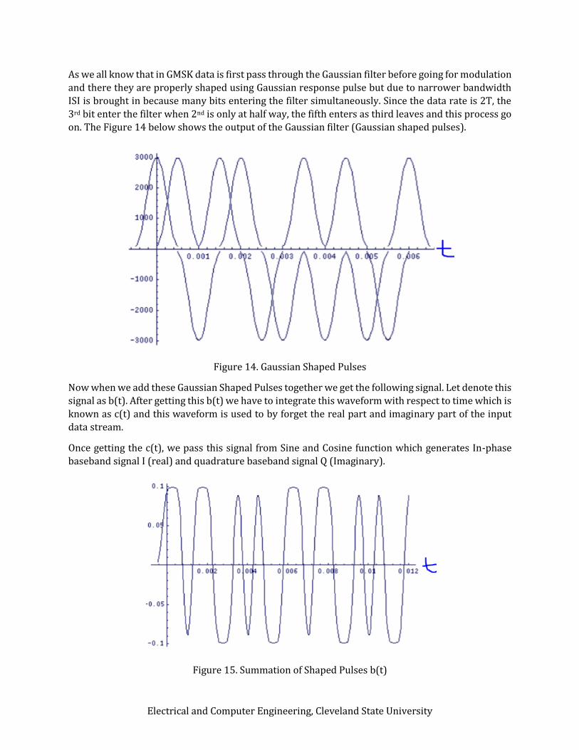
As we all know that in GMSK data is first pass through the Gaussian filter before going for modulation
and there they are properly shaped using Gaussian response pulse but due to narrower bandwidth
ISI is brought in because many bits entering the filter simultaneously. Since the data rate is 2T, the
3rd bit enter the filter when 2nd is only at half way, the fifth enters as third leaves and this process go
on. The Figure 14 below shows the output of the Gaussian filter (Gaussian shaped pulses).
Figure 14. Gaussian Shaped Pulses
Now when we add these Gaussian Shaped Pulses together we get the following signal. Let denote this
signal as b(t). After getting this b(t) we have to integrate this waveform with respect to time which is
known as c(t) and this waveform is used to by forget the real part and imaginary part of the input
data stream.
Once getting the c(t), we pass this signal from Sine and Cosine function which generates In-phase
baseband signal I (real) and quadrature baseband signal Q (Imaginary).
Figure 15. Summation of Shaped Pulses b(t)
Electrical and Computer Engineering, Cleveland State University
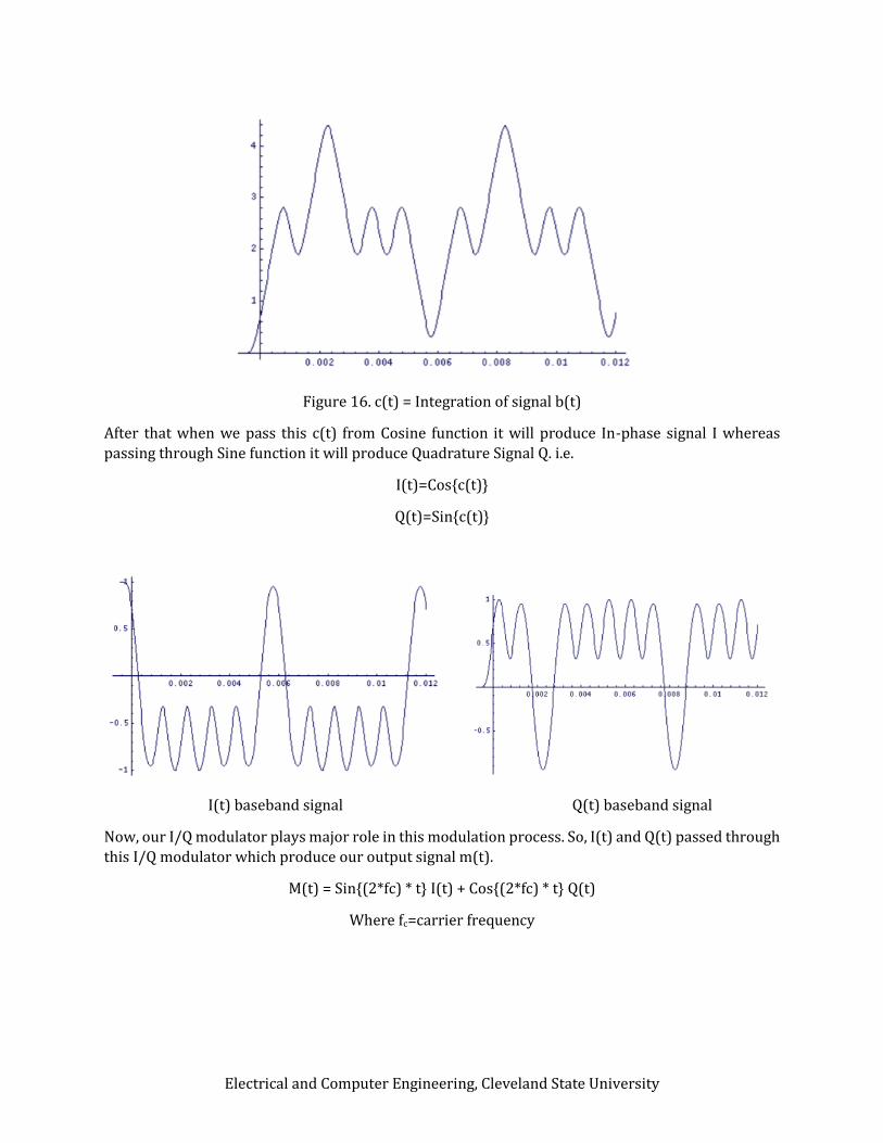
Figure 16. c(t) = Integration of signal b(t)
After that when we pass this c(t) from Cosine function it will produce In-phase signal I whereas
passing through Sine function it will produce Quadrature Signal Q. i.e.
I(t)=Cos{c(t)}
Q(t)=Sin{c(t)}
I(t) baseband signal Q(t) baseband signal
Now, our I/Q modulator plays major role in this modulation process. So, I(t) and Q(t) passed through
this I/Q modulator which produce our output signal m(t).
Electrical and Computer Engineering, Cleveland State University
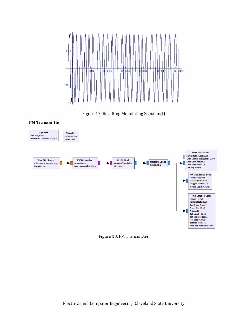
Figure 17: Resulting Modulating Signal m(t)
FM Transmitter
Figure 18. FM Transmitter
Electrical and Computer Engineering, Cleveland State University
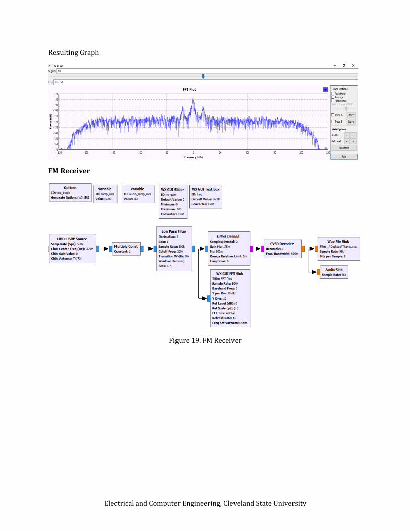
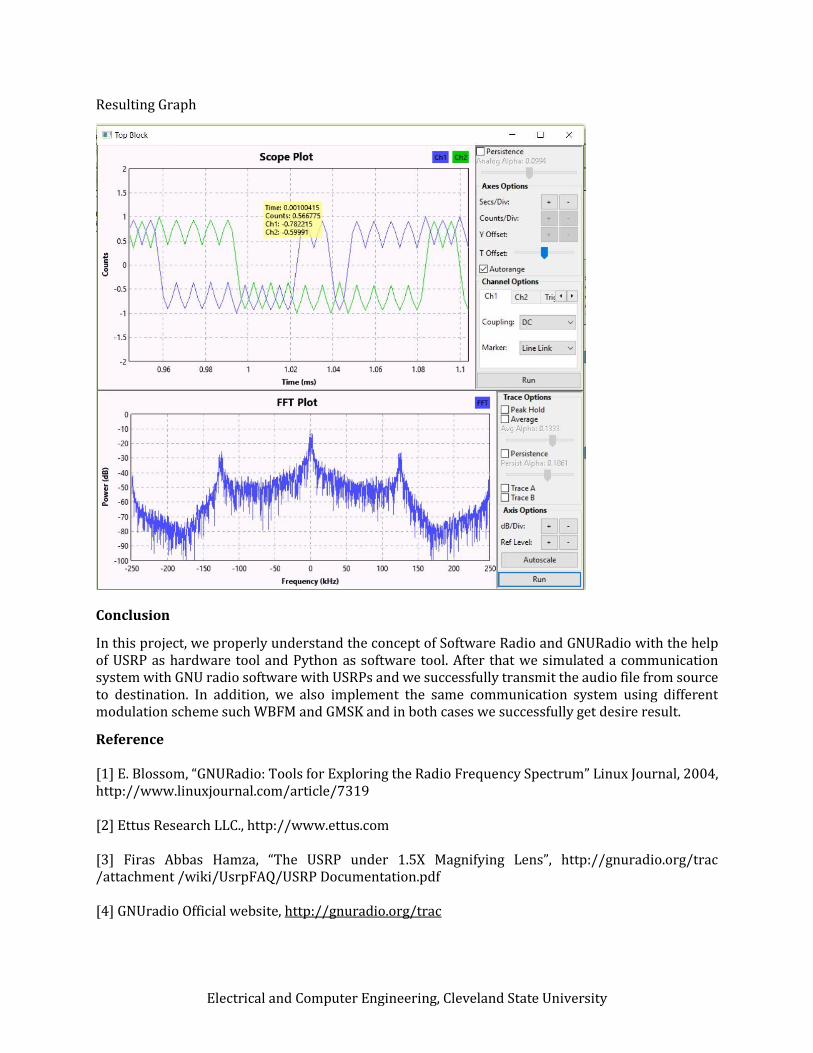
Resulting Graph
FM Receiver
Figure 19. FM Receiver
Electrical and Computer Engineering, Cleveland State University
Resulting Graph
Conclusion
In this project, we properly understand the concept of Software Radio and GNURadio with the help of USRP as hardware tool and Python as software tool. After that we simulated a communication system with GNU radio software with USRPs and we successfully transmit the audio file from source to destination. In addition, we also implement the same communication system using different modulation scheme such WBFM and GMSK and in both cases we successfully get desire result.
Reference [1] E. Blossom, “GNURadio: Tools for Exploring the Radio Frequency Spectrum” Linux Journal, 2004, http://www.linuxjournal.com/article/7319 [2] Ettus Research LLC., http://www.ettus.com [3] Firas Abbas Hamza, “The USRP under 1.5X Magnifying Lens”, http://gnuradio.org/trac /attachment /wiki/UsrpFAQ/USRP Documentation.pdf [4] GNUradio Official website, http://gnuradio.org/trac