33
Audio Power Amplifiers D. G. Meyer School of Electrical & Computer Engineering
Audio Power Amplifiers
D. G. MeyerSchool of Electrical & Computer
Engineering
Outline• How much power do I need?• How does loudspeaker cable affect
performance?• Audio Power Amplifier Classes
–A–A–B–AB–G–H–D–I
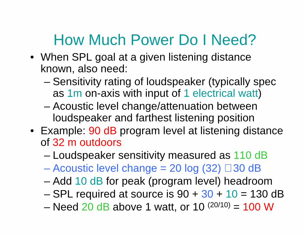
How Much Power Do I Need?• When SPL goal at a given listening distance
known, also need:– Sensitivity rating of loudspeaker (typically spec
as 1m on-axis with input of 1 electrical watt)– Acoustic level change/attenuation between
loudspeaker and farthest listening positionloudspeaker and farthest listening position• Example: 90 dB program level at listening distance
of 32 m outdoors– Loudspeaker sensitivity measured as 110 dB– Acoustic level change = 20 log (32) ≅ 30 dB– Add 10 dB for peak (program level) headroom– SPL required at source is 90 + 30 + 10 = 130 dB– Need 20 dB above 1 watt, or 10 (20/10) = 100 W
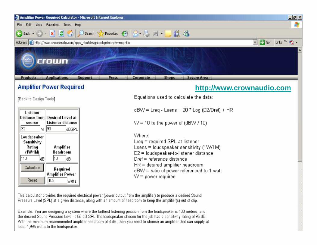
http://www.crownaudio.com
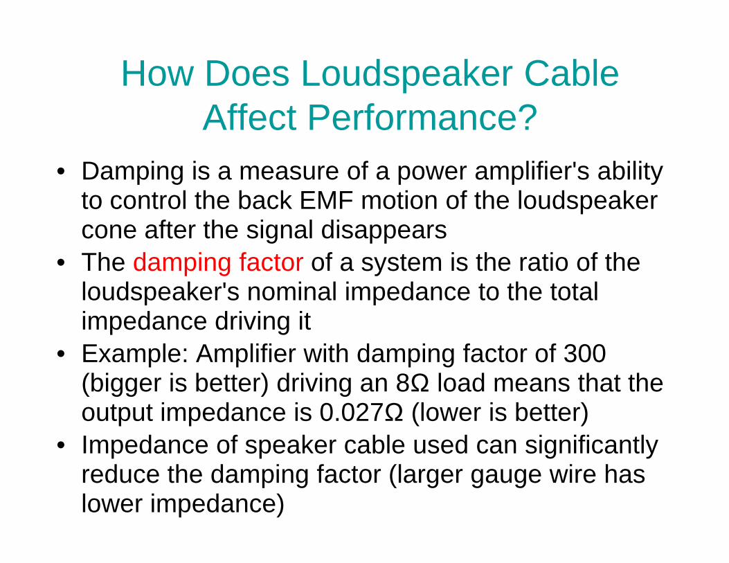
How Does Loudspeaker Cable Affect Performance?
• Damping is a measure of a power amplifier's ability to control the back EMF motion of the loudspeaker cone after the signal disappears
• The damping factor of a system is the ratio of the loudspeaker's nominal impedance to the total loudspeaker's nominal impedance to the total impedance driving it
• Example: Amplifier with damping factor of 300 (bigger is better) driving an 8Ω load means that the output impedance is 0.027Ω (lower is better)
• Impedance of speaker cable used can significantly reduce the damping factor (larger gauge wire has lower impedance)


Audio Power Amplifier Classes• Audio power amplifiers were originally classified
according to the relationship between the output voltage swing and the input voltage swing
• Classification was based on the amount of time the output devices operate during one complete cycle of a signal swinga signal swing
• Classes were also defined in terms of output bias current (the amount of current flowing in the output devices with no applied signal)
• For discussion purposes (with the exception of class A), assume a simple output stage consisting of two complementary devices (one positive polarity and one negative polarity) using any type of transistor

Basic Power Amplifier Output Stage(Voltage-Follower MOSFET Configuration)
+V
-V
Vin Vout
acts as a current amplifier with high input impedance and very low output impedance

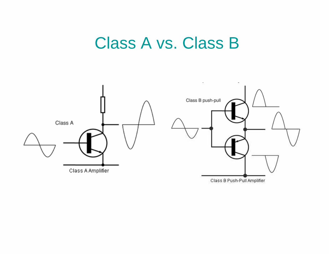
Power Amplifier Classes – “A”• Class “A”
– key ingredient of class A operation is that output device is always on
– single-ended design with only one type polarity output device
– the most inefficient of all power amplifier – the most inefficient of all power amplifier designs, averaging only around 20% (large, heavy, and run very hot)
– are inherently the most linear, with the least amount of distortion
– impractical for professional audio applications due to inefficiency

Example: Hawk A18 (2x10W)

Power Amplifier Classes – “B”• Class “B”
– opposite of class A: both output devices are never allowed to be on at the same time
– each output device is on for exactly one half of a complete sinusoidal signal cycle
– class B designs show high efficiency but poor – class B designs show high efficiency but poor linearity around the crossover region (due to the time it takes to turn one device off and the other device on, which translates into extreme crossover distortion )
– class B designs restricted to low power applications, e.g., battery operated equipment, such as communications audio
Class A vs. Class B
Power Amplifier Classes – “AB”• Class “AB”
– intermediate case: both devices are allowed to be on at the same time, but just barely
– output bias is set so that current flows in a specific output device appreciably more than a half cycle but less than the entire cycle (enough half cycle but less than the entire cycle (enough to keep each device operating so they respond instantly to input voltage demands)
– the inherent non-linearity of class B designs is eliminated, without the gross inefficiencies of the class A design
– combination of good efficiency (around 50%) with excellent linearity that makes class AB the most popular consumer audio amplifier design

Class AB
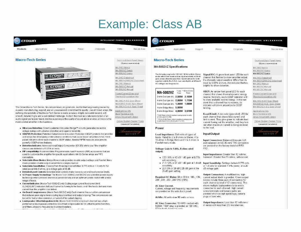
Example: Class AB

Power Amplifier Classes – “G”• Class “G”
– operation involves changing the power supply voltage from a lower level to a higher level when larger output swings are required
– common for pro audio designs– several ways to do this:
• simplest involves a single class AB output stage that is • simplest involves a single class AB output stage that is connected to two power supply rails by a diode or transistor
– for most musical program material, the output stage is connected to the lower supply voltage
– automatically switches to the higher rails for large signal peaks (thus the nickname rail-switcher)
• Another approach uses two class AB output stages, each connected to a different power supply voltage
– the magnitude of the input signal determines the signal path
– use of two power supplies improves efficiency enough to allow significantly more power for a given size/weight

Class G
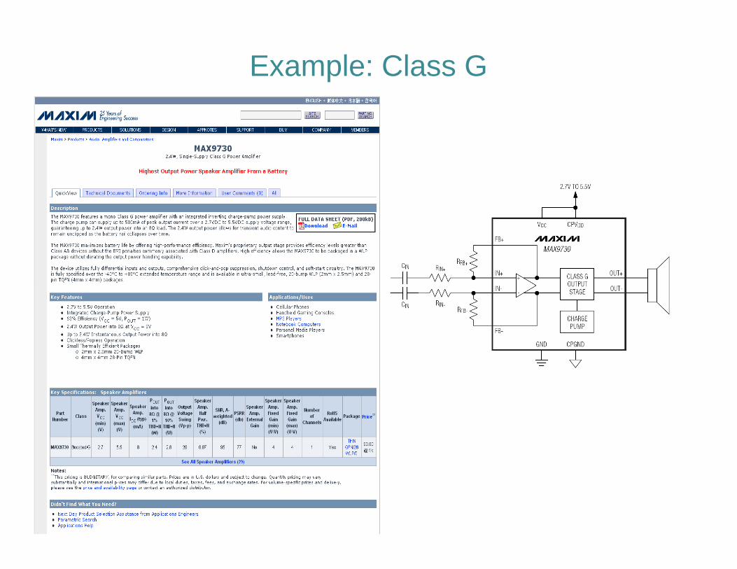
Example: Class G

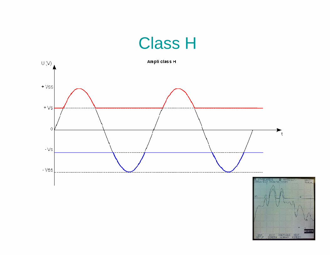
Power Amplifier Classes – “H”• Class “H”
– takes the class G design one step further and actually modulates the higher power supply voltage by the input signal
– allows the power supply to track the audio input and provide just enough voltage for optimum and provide just enough voltage for optimum operation of the output devices (thus the nickname rail-tracker or tracking power amplifier)
– the efficiency of class H is comparable to class G designs
Class H
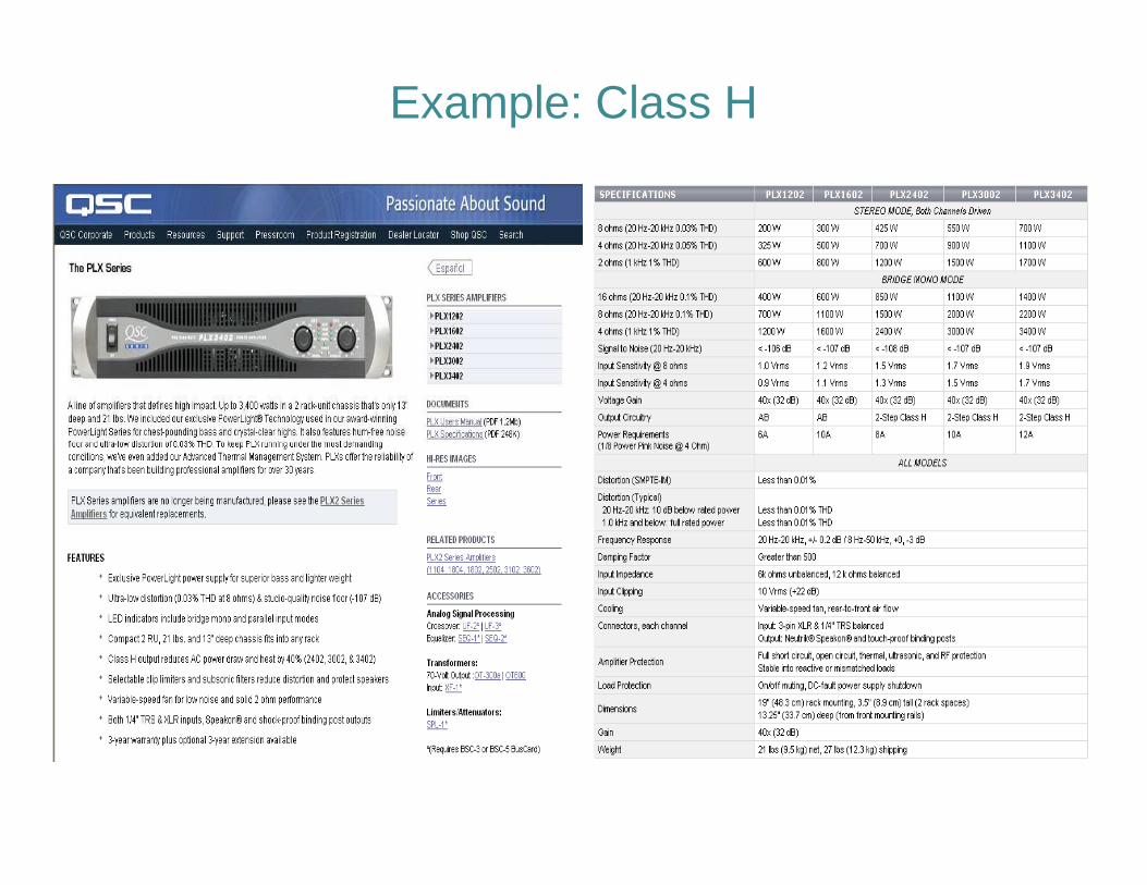
Example: Class H

More Efficient Linear Designs
AB G2
wasted power
G3 H
Power Amplifier Classes• Class “D”
– operation is switching, hence the term switching power amplifier
– output devices are rapidly switched on and off at least twice for each cycle
– the output devices are either completely on or completely off so theoretically they do not completely off so theoretically they do not dissipate any power
– class D operation is theoretically 100% efficient, but this requires zero on-impedance switches with infinitely fast switching times
– practical designs do exist with true efficiencies approaching 90%
– Class D is at least as old as 1954 (U.S. Patent 2,821,639: solid-state full-bridge servo amplifier)
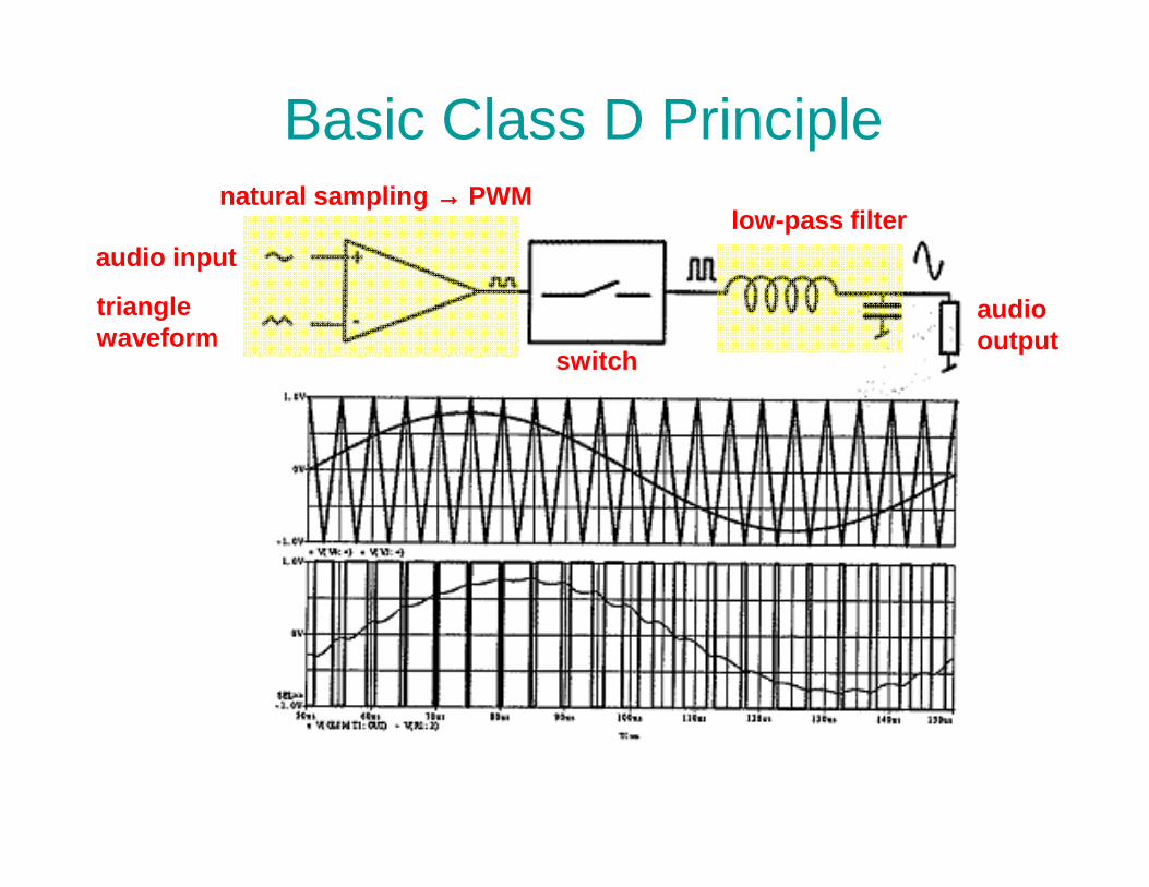
Basic Class D Principle
low-pass filternatural sampling →→→→ PWM
audio input
triangle waveform
audio output
switch
Power Amplifier Classes – “D”• Class “D” – Complications
– need to operate at high switching speed (e.g., 250 KHz) for full audio bandwidth (20 KHz) reproduction with low distortion
– traditional design requires “dead time” between positive and negative polarity phases (to avoid positive and negative polarity phases (to avoid destruction of output switching devices) –introduces additional distortion
– quality of switching devices (“on” resistance, switching speed) limit efficiency/performance

Example: Class D

Example: Class D

Power Amplifier Classes – “S”• Class “S”
– first invented in 1932– used for both amplification and amplitude
modulation– similar to Class D except the rectangular PWM
voltage waveform is applied to a low-pass filter voltage waveform is applied to a low-pass filter that allows only the slowly varying DC or average voltage component to appear across the load
– essentially this is what is called “Class D” today
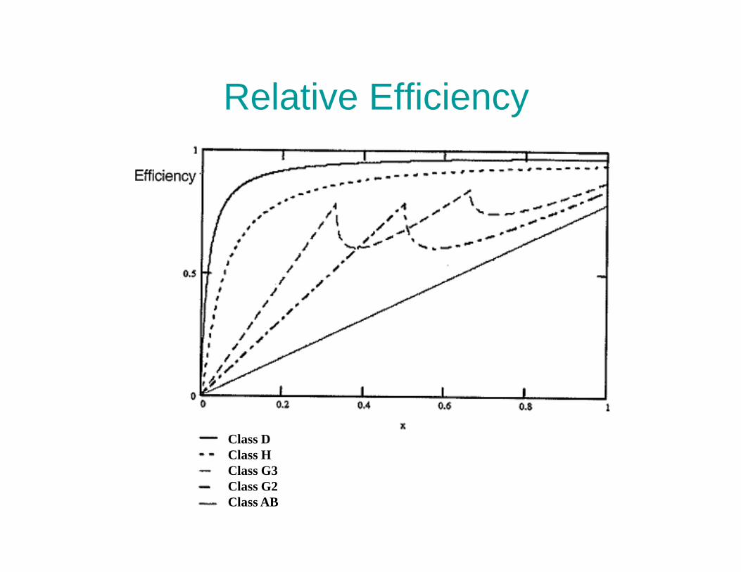
Relative Efficiency
Class DClass HClass G3Class G2Class AB

Power Amplifier Classes – “I”• Class “I”
– based on patent U.S. 5,657,219 covering opposed current converters
– "I" is short for "interleave" as this is the only four-quadrant converter known that uses two switches yet that has an interleave number of 2 yet that has an interleave number of 2
– when used with fixed-frequency naturally sampled two-sided PWM it forms a theoretically optimum converter having the least unnecessary/undesirable PWM spectra
– also called a “balanced current amplifier”
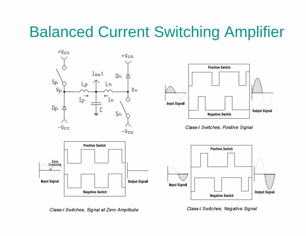
Balanced Current Switching Amplifier

Example: Class I
Industry Trends• Analog amplifier (“Class AB”) market share $2-3B in
2003 (Class D market share was only 2-3%)• By 2006, digital amplifier (“Class D”) market share
rose to 15% and by 2008 to 30%• By 2011, Class D market share predicted to be 67%• By 2011, Class D market share predicted to be 67%• Conclusion: Class D is here to stay!


