AV-1 AUDIO VISUAL, NAVIGATION & TELEPHONE SYS- TEM K ELECTRICAL CONTENTS C D E F G H I J L M SECTION AV A B AV Revision: 2004 April 2002 Q45 AUDIO VISUAL, NAVIGATION & TELEPHONE SYSTEM PRECAUTIONS ......................................................... 3 Precautions for Supplemental Restraint System (SRS) “AIR BAG” and “SEAT BELT PRE-TEN- SIONER” ................................................................. 3 Wiring Diagrams and Trouble Diagnosis ................. 3 AUDIO ........................................................................ 4 System Description ................................................. 4 AUDIO SYSTEM .................................................. 4 AV COMMUNICATION LINE ................................ 4 Schematic ............................................................... 5 Wiring Diagram—AUDIO— ..................................... 6 Wiring Diagram —REMOTE— .............................. 12 Wiring Diagram —CD AUTO CHANGER— .......... 13 Terminals and Reference Value for Bose Speaker Amplifier ................................................................ 14 Terminals and Reference Value for Audio Unit ...... 16 Terminals and Reference Value for CD Auto Changer ................................................................ 19 Terminals and Reference Value for Rear Control Switch .................................................................... 20 Self-Diagnosis Function ........................................ 20 DESCRIPTION ................................................... 20 DIAGNOSIS ITEM .............................................. 20 Self-Diagnosis Mode ............................................. 20 OPERATION PROCEDURE .............................. 20 Confirmation/Adjustment Mode ............................. 20 OPERATION PROCEDURE .............................. 20 Trouble Diagnosis ................................................. 21 PROBLEM WITH RADIO, TAPE AND CD ......... 21 FOR RADIO ONLY ............................................. 22 FOR CASSETTE PLAYER ONLY ...................... 22 FOR CD ONLY ................................................... 22 Noise Inspection .................................................... 23 TYPE OF NOISE AND POSSIBLE CAUSE ....... 23 Power Supply Circuit Inspection ........................... 23 Audio System Does Not Turn On .......................... 24 Steering Switch Does Not Operate ....................... 25 Rear Control Switch Audio Operation Does Not Work ...................................................................... 26 Removal and Installation of Audio Unit ................. 27 Removal and Installation of CD Auto Changer ...... 27 Removal and Installation of Door Speaker ............ 28 Removal and Installation of Instrument Panel Speaker ................................................................. 28 Removal and Installation of Woofer ....................... 28 Removal and Installation of Bose Speaker Amplifier ... 28 Removal and Installation of Steering Wheel Switch ... 29 Removal and Installation of Rear Control Switch ... 29 AUDIO ANTENNA ................................................... 30 Wiring Diagram —W/ANT— .................................. 30 Location of Antenna ............................................... 31 Window Antenna Repair ........................................ 31 ELEMENT CHECK ............................................. 31 TELEPHONE (PRE WIRE) ...................................... 32 Wiring Diagram — PHONE — ............................... 32 NAVIGATION SYSTEM ............................................ 33 System Description ................................................ 33 TRAVEL DISTANCE ........................................... 33 TRAVEL DIRECTION ......................................... 33 MAP-MATCHING ................................................ 33 GPS (GLOBAL POSITIONING SYSTEM) ......... 34 COMPONENT DESCRIPTION ........................... 35 BIRD VIEW™ ..................................................... 36 MAP DISPLAY .................................................... 37 FUNCTION OF MULTIFUNCTION SWITCH ...... 37 “VIEW” MODE .................................................... 40 “GPS INFORMATION” MODE ............................ 40 “SAVE CURRENT LOCATION” MODE .............. 41 “QUICK STOP CUSTOMER SETTING” MODE ... 41 “AUTO RE-ROUTE” MODE ................................ 41 “TRACKING” MODE ........................................... 41 “EDIT ADDRESS BOOK” MODE ....................... 42 “HEADING” MODE ............................................. 42 “NEARBY DISPLAY ICONS” MODE .................. 42 “ADJUST CURRENT LOCATION” MODE .......... 42 “SET AVERAGE SPEED FOR ESTIMATED JOURNEY TIME” MODE .................................... 43 “CLEAR MEMORY” MODE ................................ 43 GUIDE VOLUME SETTING ............................... 43 Precautions for AV and NAVI Control Unit Replace-
Transcript
AV-1
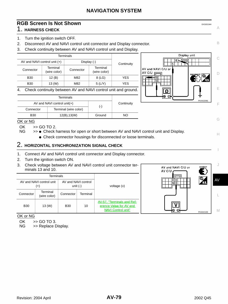
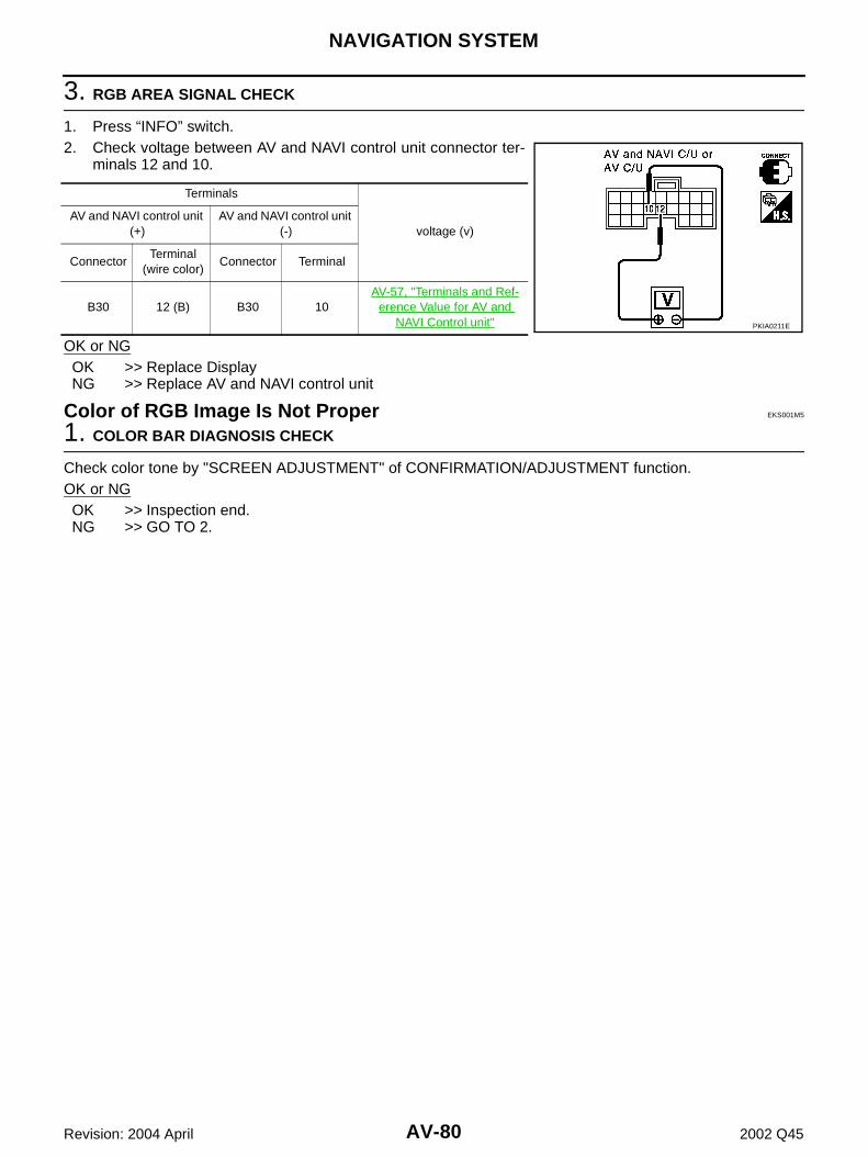
AUDIO VISUAL, NAVIGATION & TELEPHONE SYS-TEM
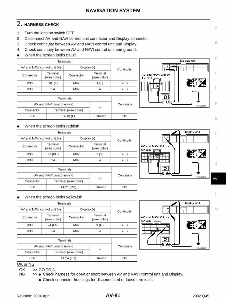
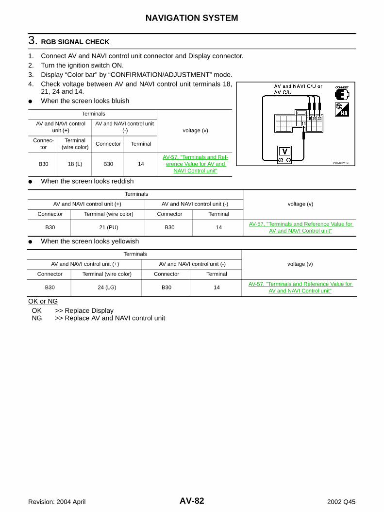
K ELECTRICAL
CONTENTS
C
D
E
F
G
H
I
J
L
M
SECTION AVA
B
AV
Revision: 2004 April 2002 Q45
AUDIO VISUAL, NAVIGATION & TELEPHONE SYSTEM
PRECAUTIONS .......................................................... 3Precautions for Supplemental Restraint System (SRS) “AIR BAG” and “SEAT BELT PRE-TEN-SIONER” .................................................................. 3Wiring Diagrams and Trouble Diagnosis .................. 3
AUDIO SYSTEM ................................................... 4AV COMMUNICATION LINE ................................. 4
Schematic ................................................................ 5Wiring Diagram—AUDIO— ...................................... 6Wiring Diagram —REMOTE— ............................... 12Wiring Diagram —CD AUTO CHANGER— ........... 13Terminals and Reference Value for Bose Speaker Amplifier ................................................................. 14Terminals and Reference Value for Audio Unit ....... 16Terminals and Reference Value for CD Auto Changer ................................................................. 19Terminals and Reference Value for Rear Control Switch ..................................................................... 20Self-Diagnosis Function ......................................... 20
Trouble Diagnosis .................................................. 21PROBLEM WITH RADIO, TAPE AND CD .......... 21FOR RADIO ONLY .............................................. 22FOR CASSETTE PLAYER ONLY ....................... 22FOR CD ONLY .................................................... 22
Noise Inspection ..................................................... 23TYPE OF NOISE AND POSSIBLE CAUSE ........ 23
Power Supply Circuit Inspection ............................ 23Audio System Does Not Turn On ........................... 24Steering Switch Does Not Operate ........................ 25Rear Control Switch Audio Operation Does Not Work ....................................................................... 26Removal and Installation of Audio Unit .................. 27
Removal and Installation of CD Auto Changer ....... 27Removal and Installation of Door Speaker ............. 28Removal and Installation of Instrument Panel Speaker .................................................................. 28Removal and Installation of Woofer ........................ 28Removal and Installation of Bose Speaker Amplifier ... 28Removal and Installation of Steering Wheel Switch ... 29Removal and Installation of Rear Control Switch ... 29
ment ........................................................................ 44Component Parts Location ..................................... 45Location of Antenna ................................................ 46Schematic ............................................................... 47Wiring Diagram —NAVI— ....................................... 48Terminals and Reference Value for AV and NAVI Control unit ............................................................. 57On Board Self-Diagnosis Function (without CON-SULT–II) .................................................................. 62
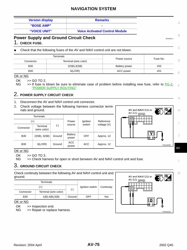
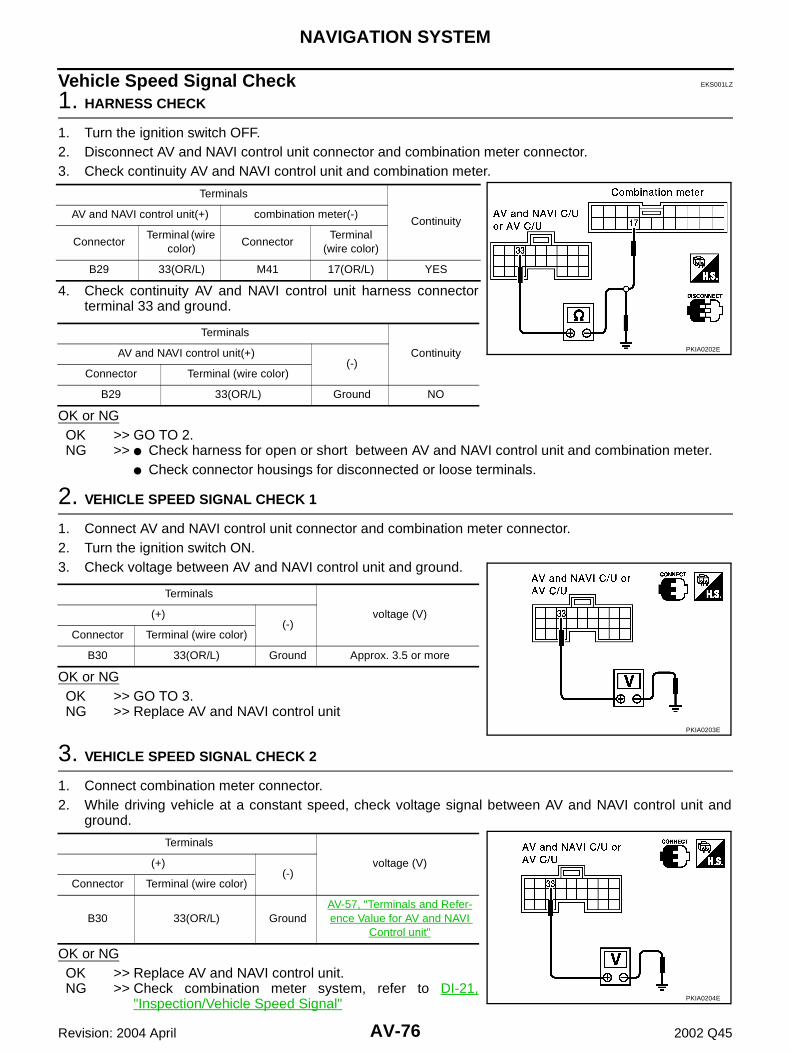
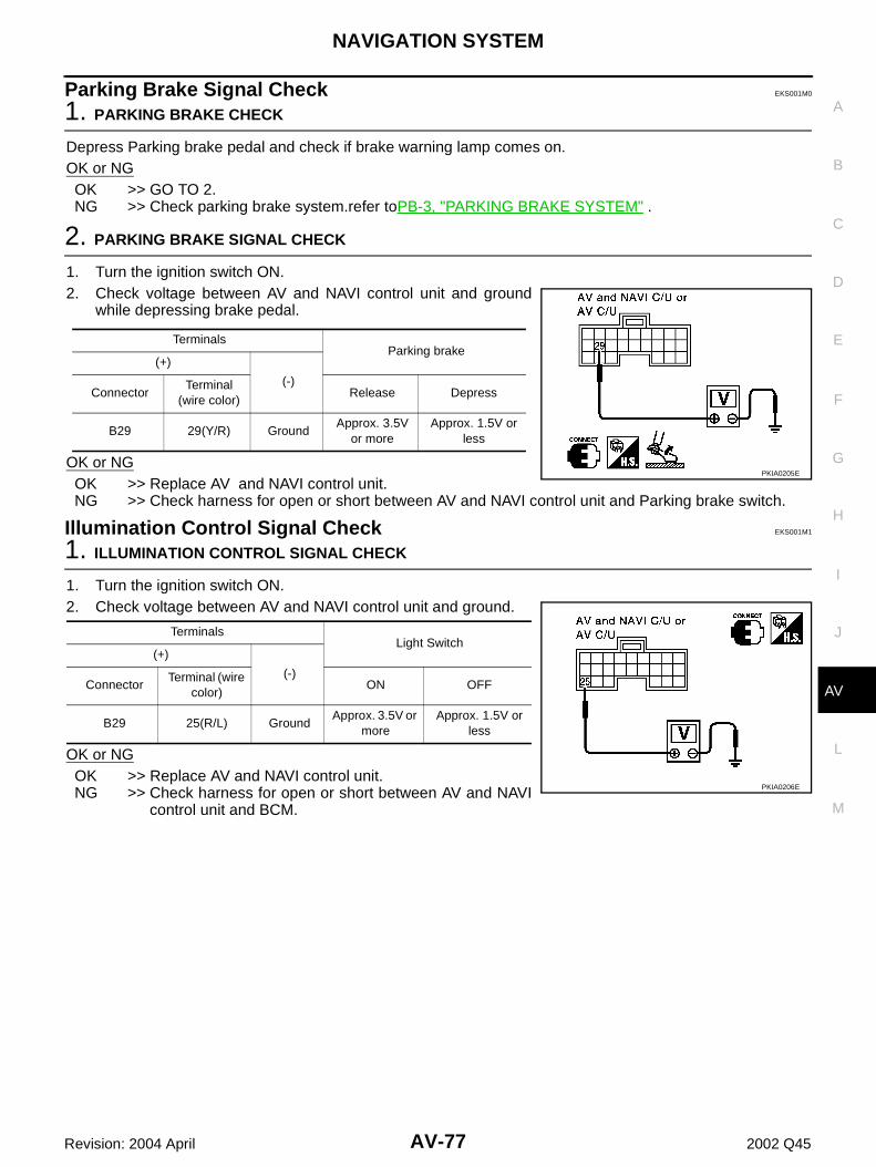
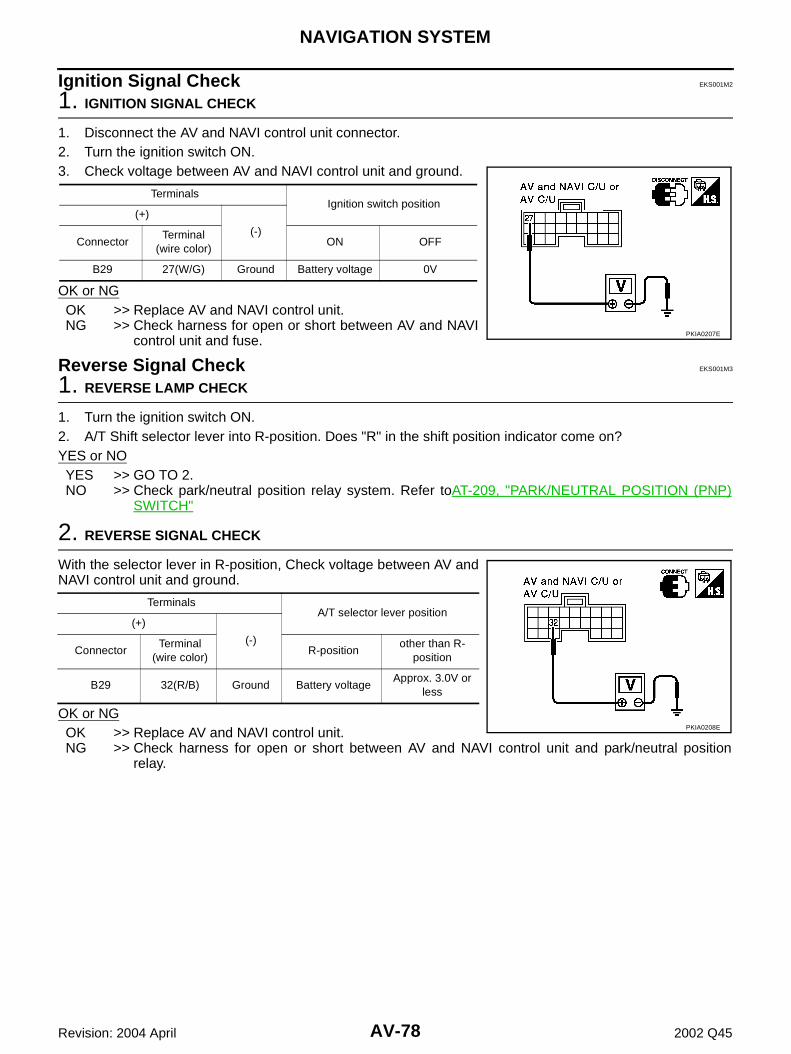
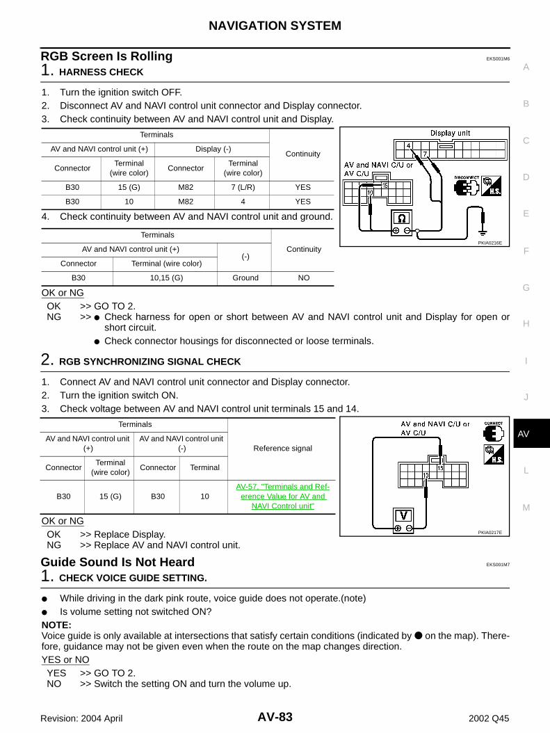
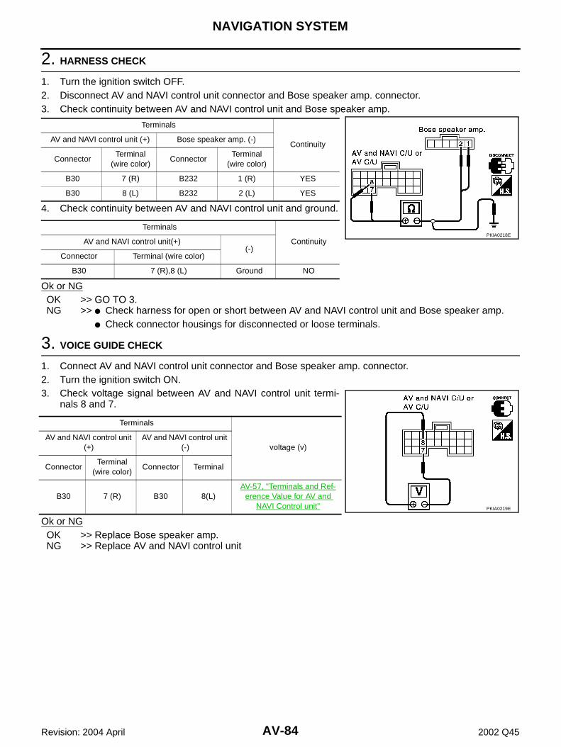
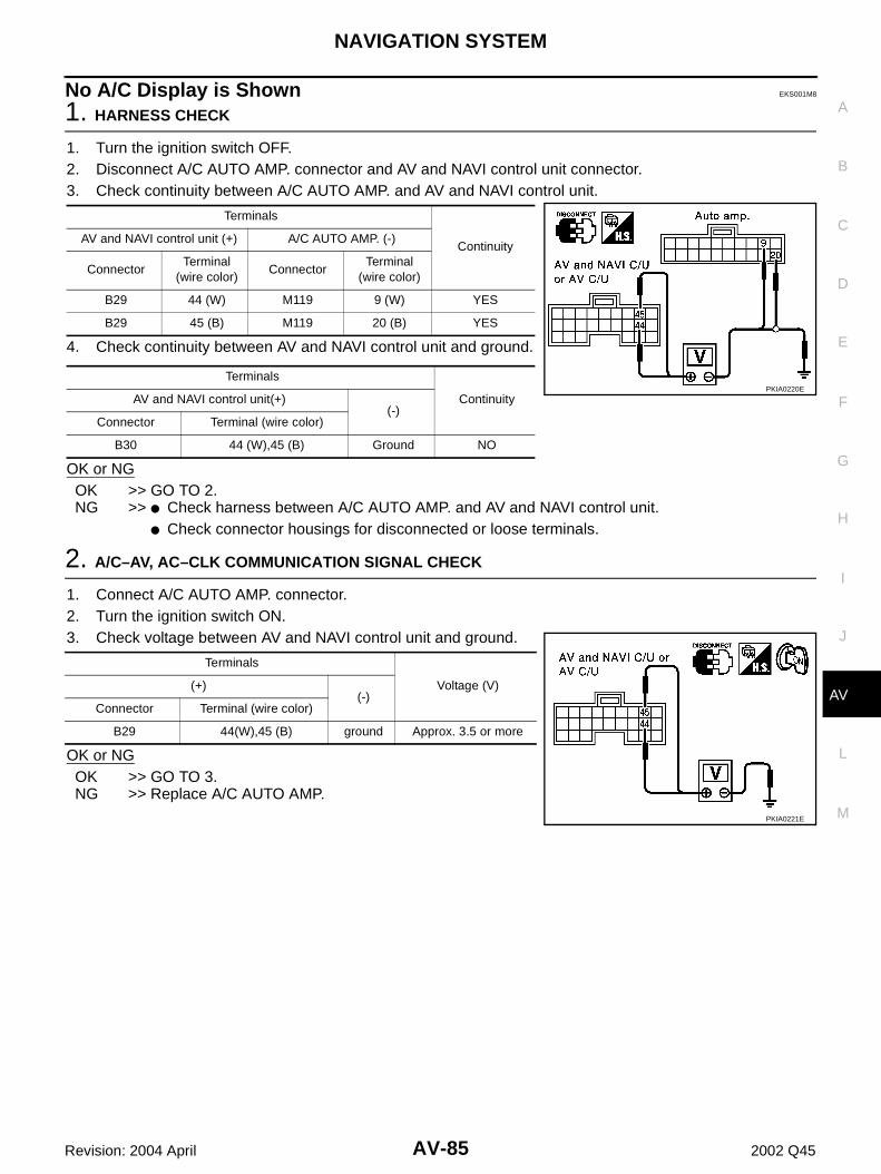
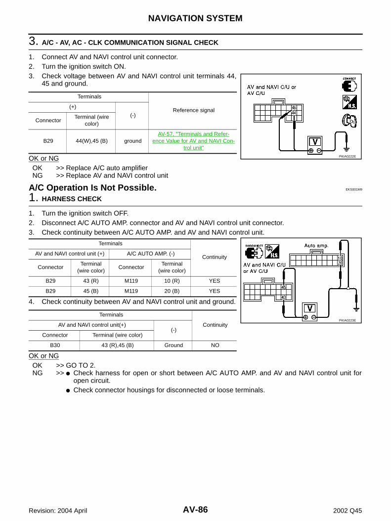
Power Supply and Ground Circuit Check ............... 75Vehicle Speed Signal Check .................................. 76Parking Brake Signal Check ................................... 77Illumination Control Signal Check ........................... 77Ignition Signal Check .............................................. 78Reverse Signal Check ............................................ 78RGB Screen Is Not Shown ..................................... 79Color of RGB Image Is Not Proper ......................... 80RGB Screen Is Rolling ............................................ 83Guide Sound Is Not Heard ..................................... 83No A/C Display is Shown ........................................ 85A/C Operation Is Not Possible. ............................... 86
No Fuel Information Is Displayed/No Warning Mes-sage Is Displayed. ...................................................88Vehicle Condition Setting Is Not Possible. ..............89Previous Conditions Are Not Stored. ......................90The Position of The Current-Location Mark Is Not Correct. ...................................................................90Radio Wave From The GPS Satellite Is Not Received. ................................................................91Driving Test .............................................................91Example of Symptoms Judged Not Abnormal ........92
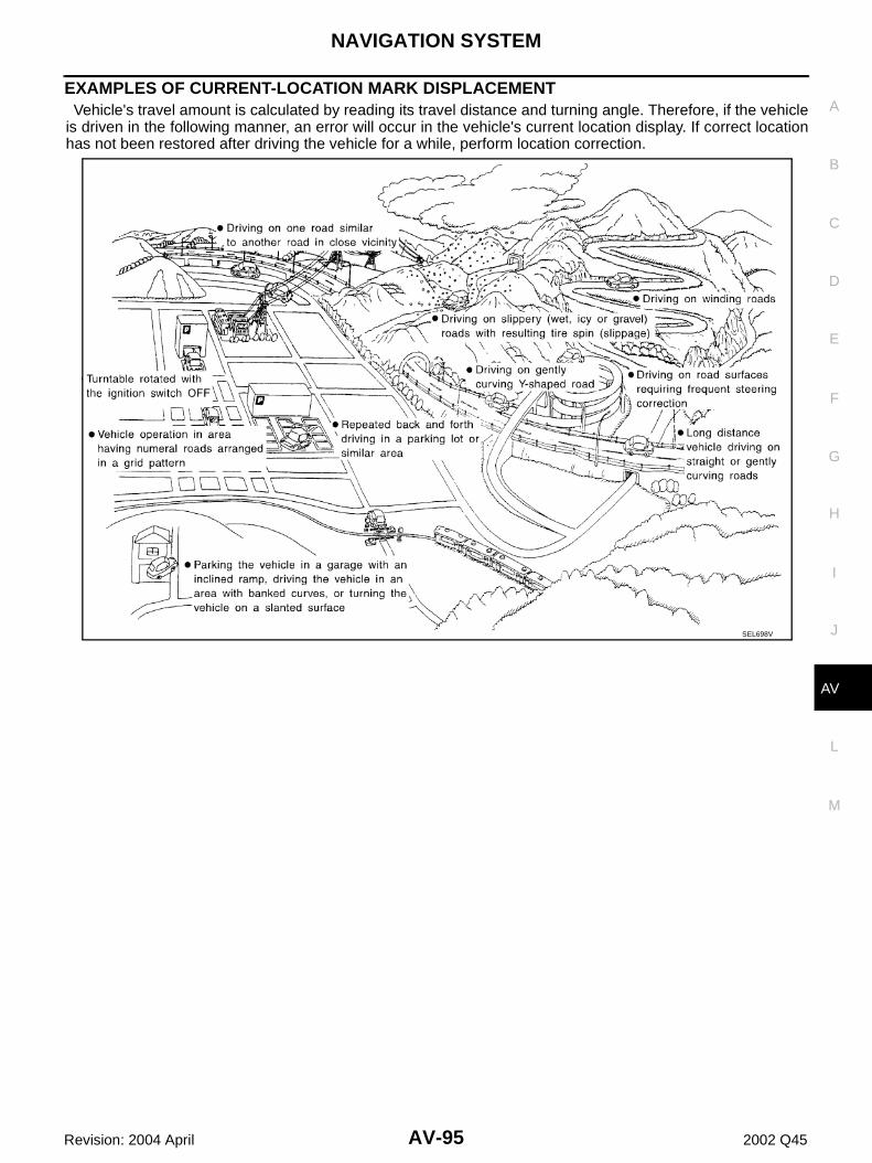
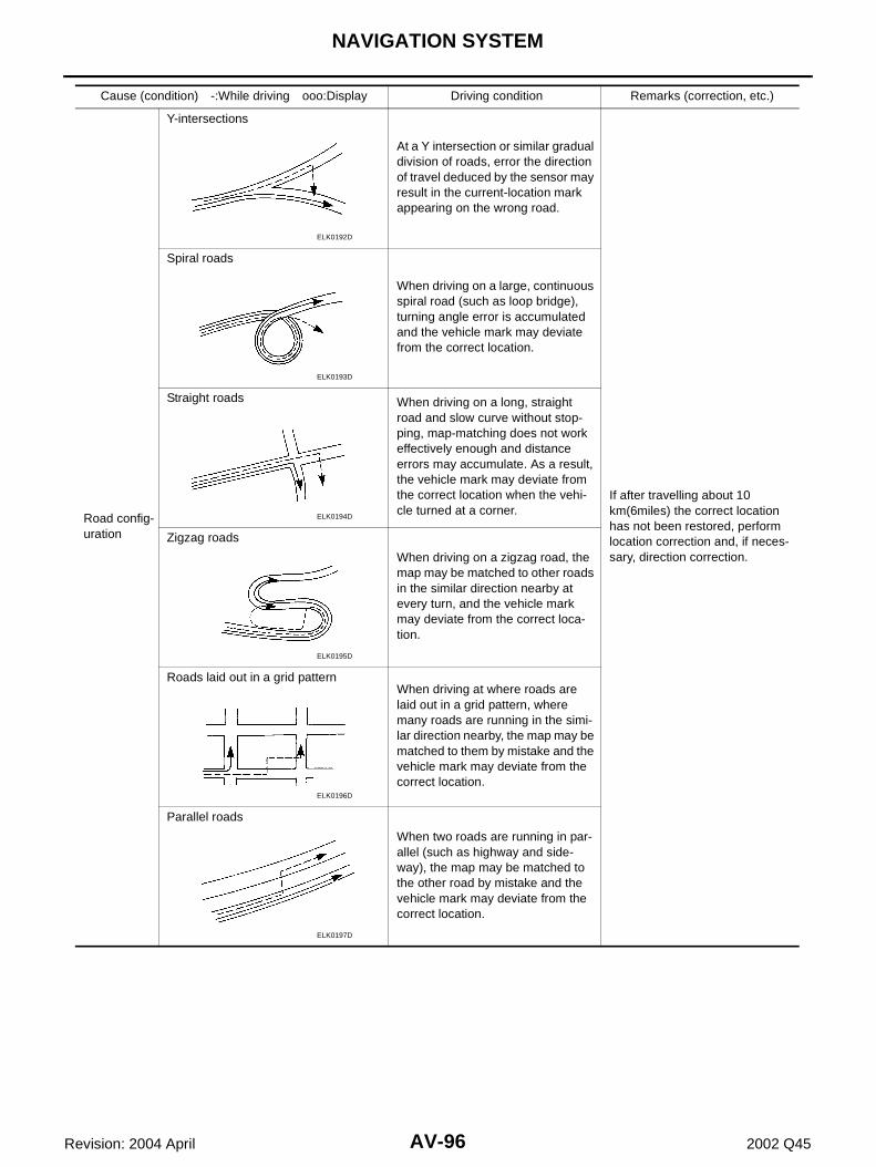
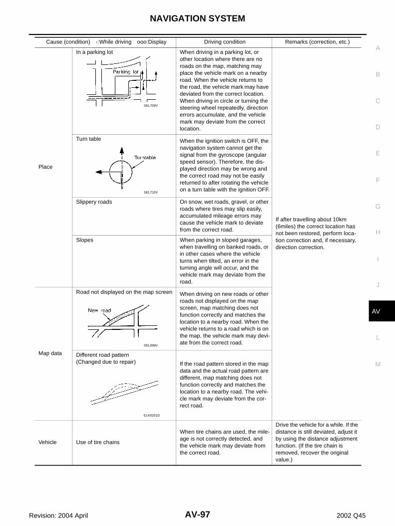
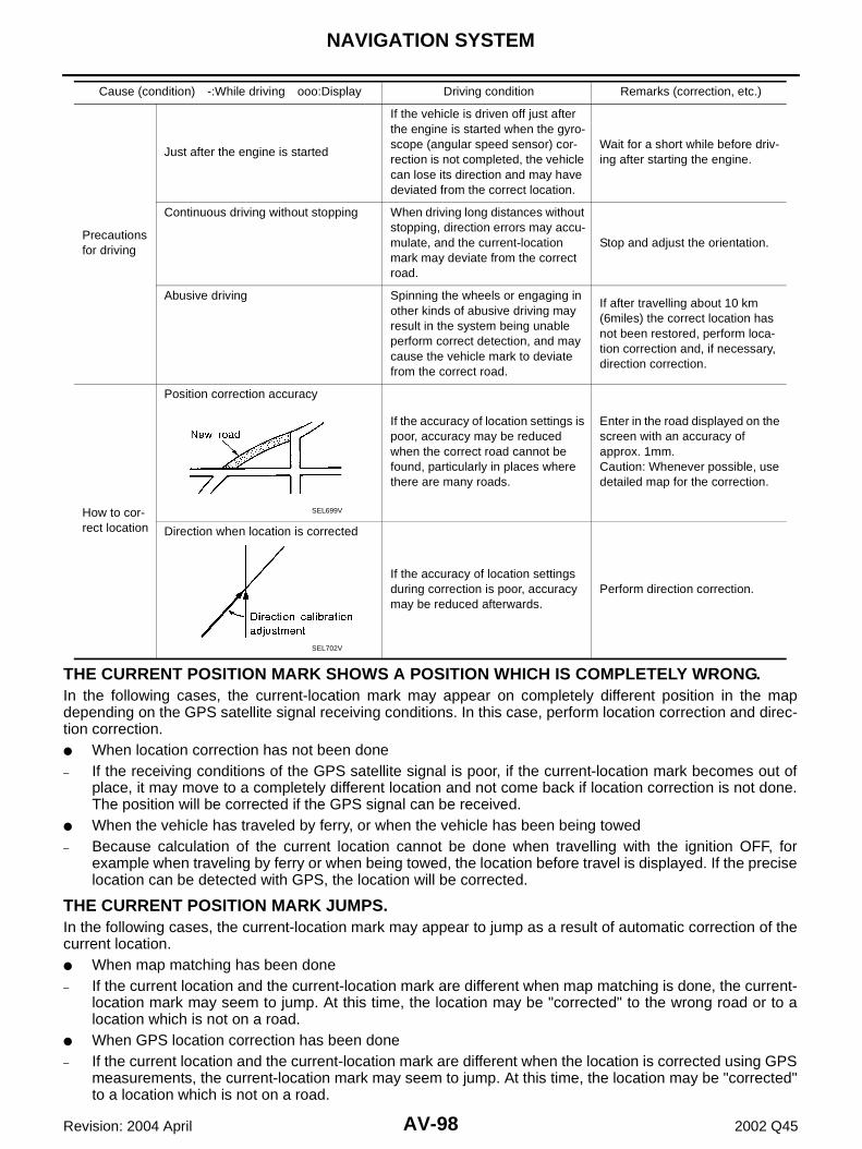
BASIC OPERATION ............................................92VEHICLE MARK ..................................................92DESTINATION, PASSING POINTS, AND MENU ITEMS CANNOT BE SELECTED/SET. ...............93VOICE GUIDE .....................................................94ROUTE SEARCHING ..........................................94EXAMPLES OF CURRENT-LOCATION MARK DISPLACEMENT .................................................95THE CURRENT POSITION MARK SHOWS A POSITION WHICH IS COMPLETELY WRONG. ...98THE CURRENT POSITION MARK JUMPS. .......98THE CURRENT LOCATION MARK IS IN A RIVER OR THE SEA. ..........................................99WHEN DRIVING ON THE SAME ROAD, SOME-TIMES THE CURRENT-LOCATION MARK IS IN THE RIGHT PLACE AND SOMETIMES IT IS THE WRONG PLACE. .................................................99LOCATION CORRECTION BY MAP MATCHING IS SLOW. .............................................................99ALTHOUGH THE GPS RECEIVING DISPLAY IS GREEN, THE VEHICLE MARK DOES NOT RETURN TO THE CORRECT LOCATION. .........99THE NAME OF THE CURRENT PLACE IS NOT DISPLAYED. ........................................................99CONTENTS OF THE DISPLAY DIFFER FOR THE BIRD VIEW™ AND THE (FLAT) MAP SCREEN. .............................................................99
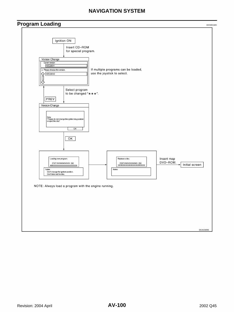
Program Loading ..................................................100Removal and Installation of AV and NAVI Control Unit ........................................................................101Removal and Installation of GPS Antenna ............101Removal and Installation of Steering Wheel Switch .101Removal and Installation of Rear Control Switch ..101
PRECAUTIONS
AV-3
C
D
E
F
G
H
I
J
L
M
A
B
AV
Revision: 2004 April 2002 Q45
PRECAUTIONS PFP:00001
Precautions for Supplemental Restraint System (SRS) “AIR BAG” and “SEAT BELT PRE-TENSIONER” EKS001C0
The Supplemental Restraint System such as “AIR BAG” and “SEAT BELT PRE-TENSIONER”, used alongwith a front seat belt, helps to reduce the risk or severity of injury to the driver and front passenger for certaintypes of collision. Information necessary to service the system safely is included in the SRS and SB section ofthis Service Manual.WARNING:● To avoid rendering the SRS inoperative, which could increase the risk of personal injury or death
in the event of a collision which would result in air bag inflation, all maintenance must be per-formed by an authorized NISSAN/INFINITI dealer.
● Improper maintenance, including incorrect removal and installation of the SRS, can lead to per-sonal injury caused by unintentional activation of the system. For removal of Spiral Cable and AirBag Module, see the SRS section.
● Do not use electrical test equipment on any circuit related to the SRS unless instructed to in thisService Manual. SRS wiring harnesses can be identified by yellow and/or orange harnesses orharness connectors.
Wiring Diagrams and Trouble Diagnosis EKS001RC
When you read wiring diagrams, refer to the followings:● Refer to GI-14, "How to Read Wiring Diagrams" .● Refer to PG-2, "POWER SUPPLY ROUTING" for power distribution circuit.When you perform trouble diagnosis, refer to the followings:● Refer to GI-10, "HOW TO FOLLOW TEST GROUPS IN TROUBLE DIAGNOSES" .● Refer to GI-26, "How to Perform Efficient Diagnosis for an Electrical Incident" .
AV-4
AUDIO
Revision: 2004 April 2002 Q45
AUDIO PFP:28111
System Description EKS0019O
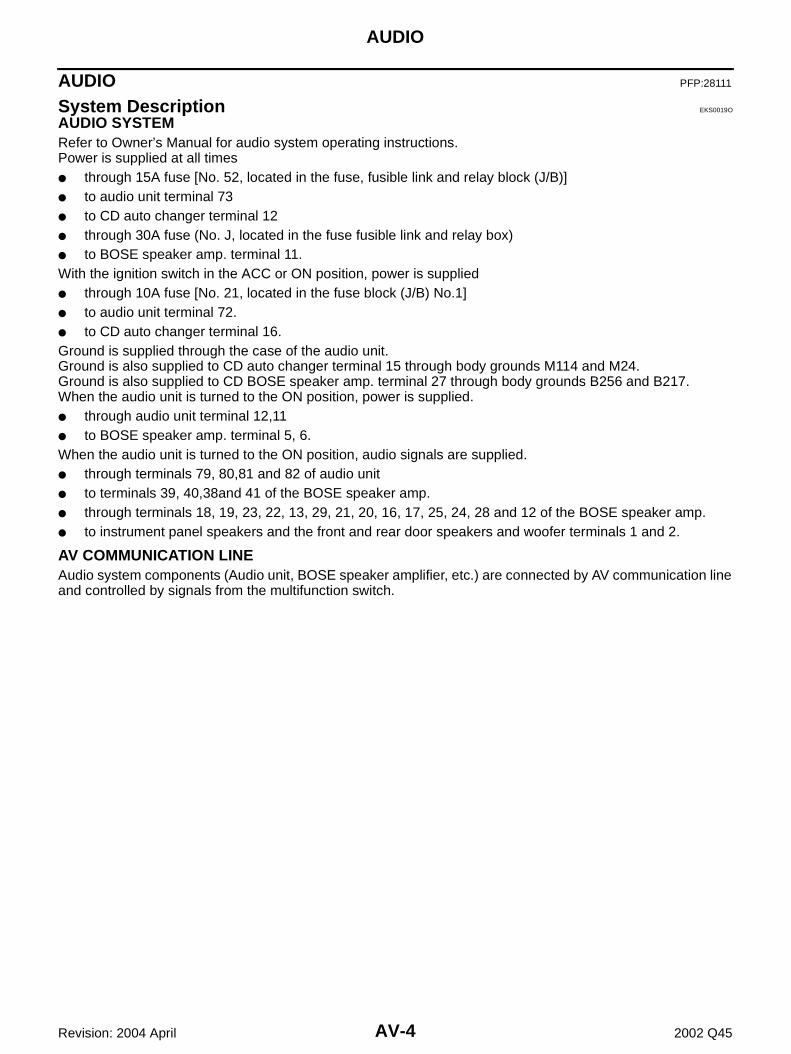
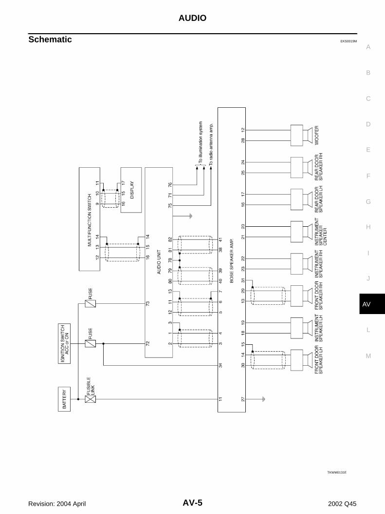
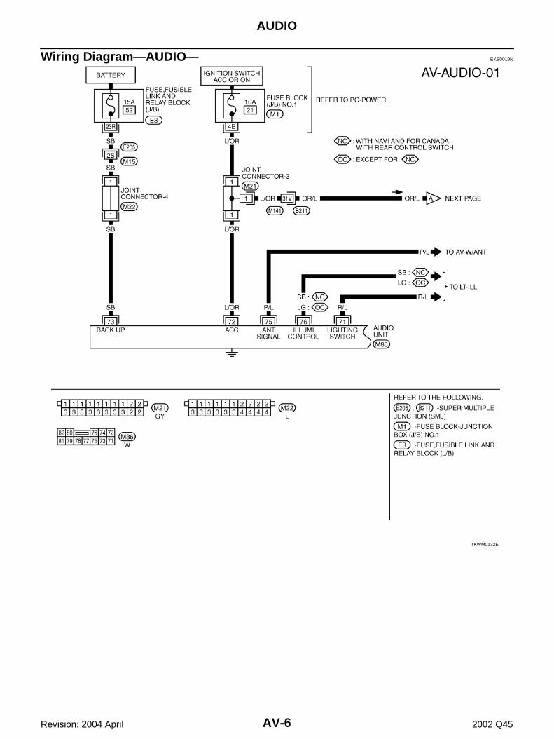
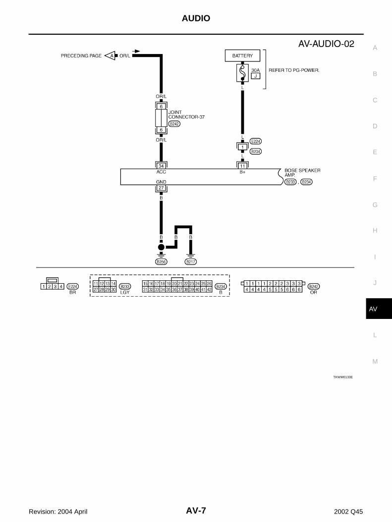
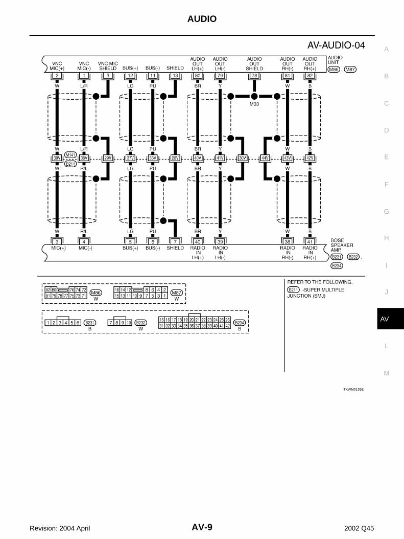
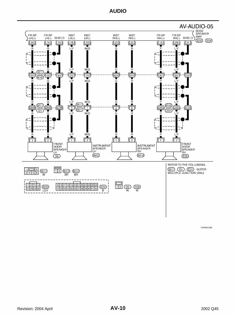
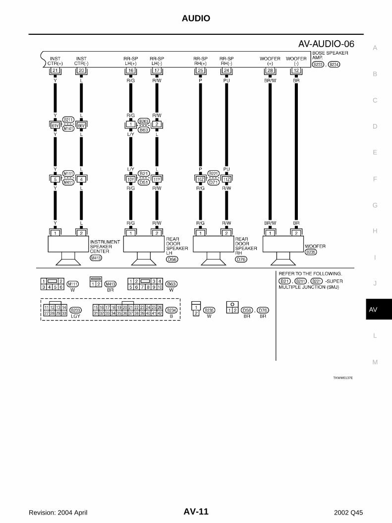
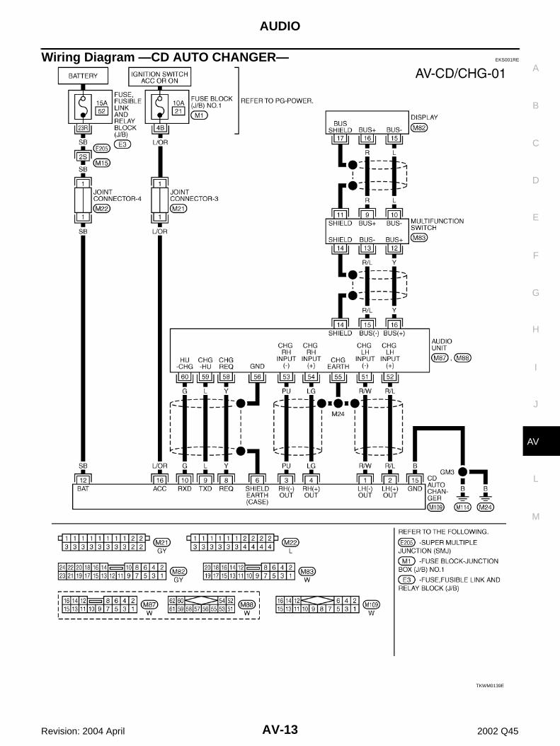
AUDIO SYSTEM Refer to Owner’s Manual for audio system operating instructions.Power is supplied at all times● through 15A fuse [No. 52, located in the fuse, fusible link and relay block (J/B)]● to audio unit terminal 73● to CD auto changer terminal 12● through 30A fuse (No. J, located in the fuse fusible link and relay box)● to BOSE speaker amp. terminal 11.With the ignition switch in the ACC or ON position, power is supplied● through 10A fuse [No. 21, located in the fuse block (J/B) No.1]● to audio unit terminal 72.● to CD auto changer terminal 16.Ground is supplied through the case of the audio unit.Ground is also supplied to CD auto changer terminal 15 through body grounds M114 and M24.Ground is also supplied to CD BOSE speaker amp. terminal 27 through body grounds B256 and B217.When the audio unit is turned to the ON position, power is supplied.● through audio unit terminal 12,11● to BOSE speaker amp. terminal 5, 6.When the audio unit is turned to the ON position, audio signals are supplied.● through terminals 79, 80,81 and 82 of audio unit● to terminals 39, 40,38and 41 of the BOSE speaker amp.● through terminals 18, 19, 23, 22, 13, 29, 21, 20, 16, 17, 25, 24, 28 and 12 of the BOSE speaker amp.● to instrument panel speakers and the front and rear door speakers and woofer terminals 1 and 2.
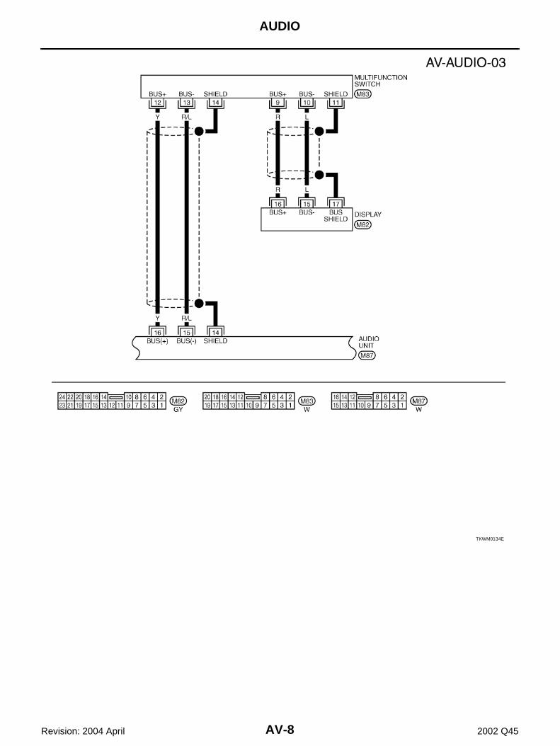
AV COMMUNICATION LINEAudio system components (Audio unit, BOSE speaker amplifier, etc.) are connected by AV communication lineand controlled by signals from the multifunction switch.
AUDIO
AV-5
C
D
E
F
G
H
I
J
L
M
A
B
AV
Revision: 2004 April 2002 Q45
Schematic EKS0019M
TKWM0131E
AV-6
AUDIO
Revision: 2004 April 2002 Q45
Wiring Diagram—AUDIO— EKS0019N
TKWM0132E
AUDIO
AV-7
C
D
E
F
G
H
I
J
L
M
A
B
AV
Revision: 2004 April 2002 Q45
TKWM0133E
AV-8
AUDIO
Revision: 2004 April 2002 Q45
TKWM0134E
AUDIO
AV-9
C
D
E
F
G
H
I
J
L
M
A
B
AV
Revision: 2004 April 2002 Q45
TKWM0135E
AV-10
AUDIO
Revision: 2004 April 2002 Q45
TKWM0136E
AUDIO
AV-11
C
D
E
F
G
H
I
J
L
M
A
B
AV
Revision: 2004 April 2002 Q45
TKWM0137E
AV-12
AUDIO
Revision: 2004 April 2002 Q45
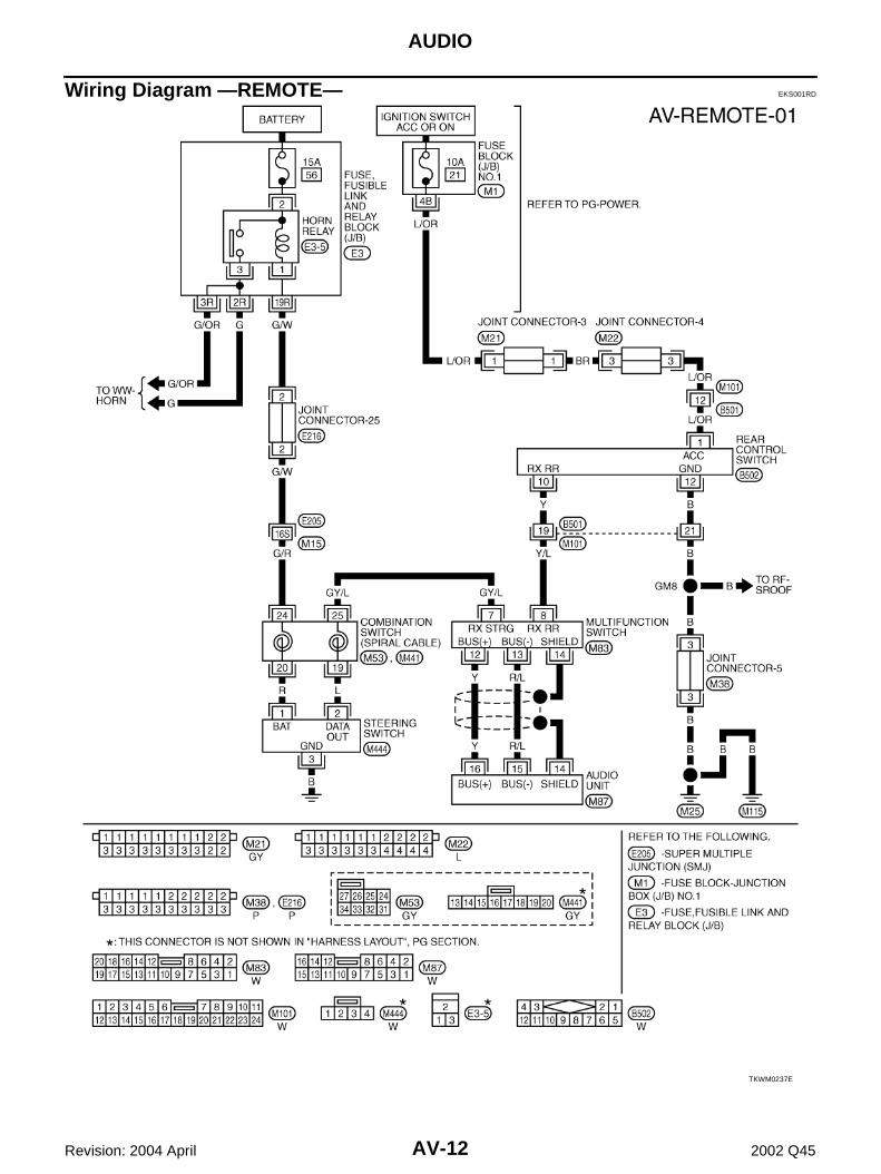
Wiring Diagram —REMOTE— EKS001RD
TKWM0237E
AUDIO
AV-13
C
D
E
F
G
H
I
J
L
M
A
B
AV
Revision: 2004 April 2002 Q45
Wiring Diagram —CD AUTO CHANGER— EKS001RE
TKWM0139E
AV-14
AUDIO
Revision: 2004 April 2002 Q45
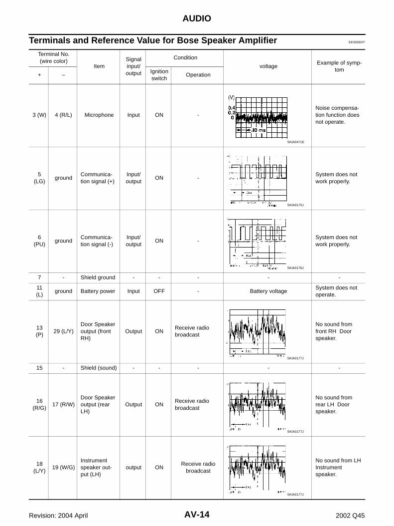
Terminals and Reference Value for Bose Speaker Amplifier EKS000XT
Terminal No. (wire color)
ItemSignal input/output
Condition
voltageExample of symp-
tom+ –
Ignition switch
Operation
3 (W) 4 (R/L) Microphone Input ON -Noise compensa-tion function does not operate.
5 (LG)
groundCommunica-tion signal (+)
Input/output
ON -System does not work properly.
6 (PU)
groundCommunica-tion signal (-)
Input/output
ON -System does not work properly.
7 - Shield ground - - - - -
11 (L)
ground Battery power Input OFF - Battery voltageSystem does not operate.
13 (P)
29 (L/Y)Door Speaker output (front RH)
Output ONReceive radio broadcast
No sound from front RH Door speaker.
15 - Shield (sound) - - - - -
16 (R/G)
17 (R/W)Door Speaker output (rear LH)
Output ONReceive radio broadcast
No sound from rear LH Door speaker.
18 (L/Y)
19 (W/G)Instrument speaker out-put (LH)
output ONReceive radio
broadcast
No sound from LH Instrument speaker.
SKIA0471E
SKIA0175J
SKIA0176J
SKIA0177J
SKIA0177J
SKIA0177J
AUDIO
AV-15
C
D
E
F
G
H
I
J
L
M
A
B
AV
Revision: 2004 April 2002 Q45
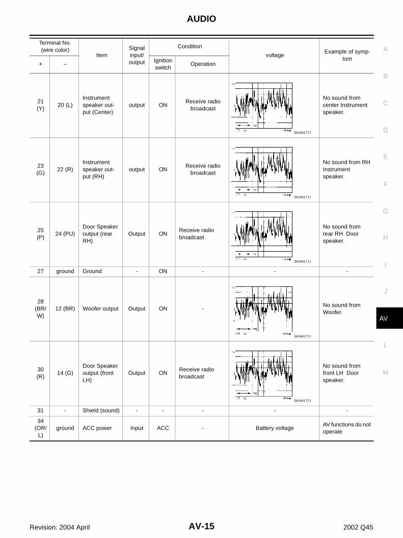
21 (Y)
20 (L)Instrument speaker out-put (Center)
output ONReceive radio
broadcast
No sound from center Instrument speaker.
23 (G)
22 (R)Instrument speaker out-put (RH)
output ONReceive radio
broadcast
No sound from RH Instrument speaker.
25 (P)
24 (PU)Door Speaker output (rear RH)
Output ONReceive radio broadcast
No sound from rear RH Door speaker.
27 ground Ground - ON - - -
28 (BR/W)
12 (BR) Woofer output Output ON -No sound from Woofer.
30 (R)
14 (G)Door Speaker output (front LH)
Output ONReceive radio broadcast
No sound from front LH Door speaker.
31 - Shield (sound) - - - - -
34 (OR/
L)ground ACC power Input ACC - Battery voltage
AV functions do not operate
Terminal No. (wire color)
ItemSignal input/output
Condition
voltageExample of symp-
tom+ –
Ignition switch
Operation
SKIA0177J
SKIA0177J
SKIA0177J
SKIA0177J
SKIA0177J
AV-16
AUDIO
Revision: 2004 April 2002 Q45
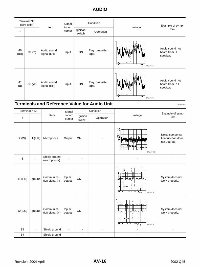
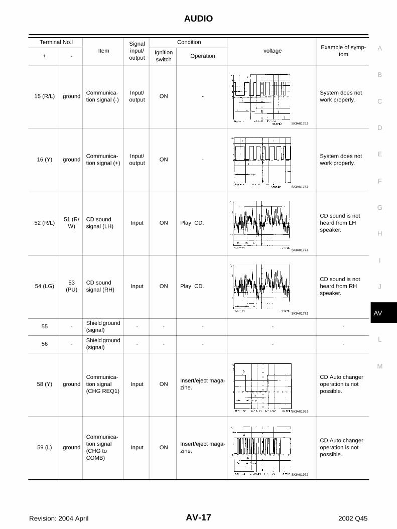
Terminals and Reference Value for Audio Unit EKS000XU
40 (BR)
39 (Y)Audio sound signal (LH)
Input ONPlay cassette tape.
Audio sound not heard from LH speaker.
41 (B)
38 (W)Audio sound signal (RH)
Input ONPlay cassette tape.
Audio sound not heard from RH speaker.
Terminal No. (wire color)
ItemSignal input/output
Condition
voltageExample of symp-
tom+ –
Ignition switch
Operation
SKIA0177J
SKIA0177J
Terminal No.l
ItemSignal input/output
Condition
voltageExample of symp-
tom+ -Ignition switch
Operation
2 (W) 1 (L/R) Microphone Output ON -Noise compensa-tion function does not operate.
3 -Shield ground (microphone)
- - - - -
11 (PU) groundCommunica-tion signal (-)
Input/output
ON -System does not work properly.
12 (LG) groundCommunica-tion signal (+)
Input/output
ON -System does not work properly.
13 - Shield ground - - - - -
14 - Shield ground - - - - -
SKIA0471E
SKIA0176J
SKIA0175J
AUDIO
AV-17
C
D
E
F
G
H
I
J
L
M
A
B
AV
Revision: 2004 April 2002 Q45
15 (R/L) groundCommunica-tion signal (-)
Input/output
ON -System does not work properly.
16 (Y) groundCommunica-tion signal (+)
Input/output
ON -System does not work properly.
52 (R/L)51 (R/
W)CD sound signal (LH)
Input ON Play CD.CD sound is not heard from LH speaker.
54 (LG)53
(PU)CD sound signal (RH)
Input ON Play CD.CD sound is not heard from RH speaker.
55 -Shield ground (signal)
- - - - -
56 -Shield ground (signal)
- - - - -
58 (Y) groundCommunica-tion signal (CHG REQ1)
Input ONInsert/eject maga-zine.
CD Auto changer operation is not possible.
59 (L) ground
Communica-tion signal (CHG to COMB)
Input ONInsert/eject maga-zine.
CD Auto changer operation is not possible.
Terminal No.l
ItemSignal input/output
Condition
voltageExample of symp-
tom+ -Ignition switch
Operation
SKIA0176J
SKIA0175J
SKIA0177J
SKIA0177J
SKIA0196J
SKIA0197J
AV-18
AUDIO
Revision: 2004 April 2002 Q45
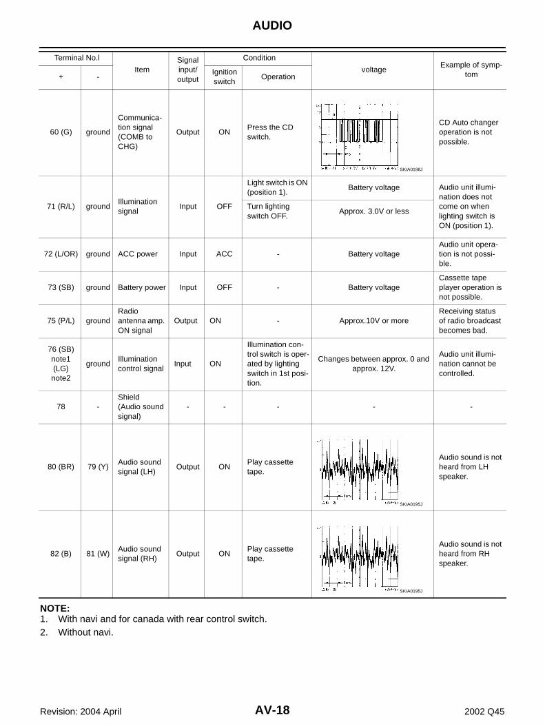
NOTE:1. With navi and for canada with rear control switch.2. Without navi.
60 (G) ground
Communica-tion signal (COMB to CHG)
Output ONPress the CD switch.
CD Auto changer operation is not possible.
71 (R/L) groundIllumination signal
Input OFF
Light switch is ON (position 1).
Battery voltage Audio unit illumi-nation does not come on when lighting switch is ON (position 1).
Turn lighting switch OFF.
Approx. 3.0V or less
72 (L/OR) ground ACC power Input ACC - Battery voltageAudio unit opera-tion is not possi-ble.
73 (SB) ground Battery power Input OFF - Battery voltageCassette tape player operation is not possible.
75 (P/L) groundRadio antenna amp. ON signal
Output ON - Approx.10V or moreReceiving status of radio broadcast becomes bad.
76 (SB) note1 (LG) note2
groundIllumination control signal
Input ON
Illumination con-trol switch is oper-ated by lighting switch in 1st posi-tion.
Changes between approx. 0 and approx. 12V.
Audio unit illumi-nation cannot be controlled.
78 -Shield(Audio sound signal)
- - - - -
80 (BR) 79 (Y)Audio sound signal (LH)
Output ONPlay cassette tape.
Audio sound is not heard from LH speaker.
82 (B) 81 (W)Audio sound signal (RH)
Output ONPlay cassette tape.
Audio sound is not heard from RH speaker.
Terminal No.l
ItemSignal input/output
Condition
voltageExample of symp-
tom+ -Ignition switch
Operation
SKIA0198J
SKIA0195J
SKIA0195J
AUDIO
AV-19
C
D
E
F
G
H
I
J
L
M
A
B
AV
Revision: 2004 April 2002 Q45
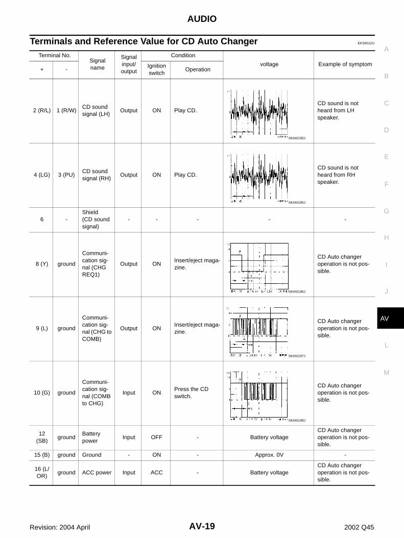
Terminals and Reference Value for CD Auto Changer EKS0012U
Terminal No.Signal name
Signal input/output
Condition
voltage Example of symptom+ -
Ignition switch
Operation
2 (R/L) 1 (R/W)CD sound signal (LH)
Output ON Play CD.CD sound is not heard from LH speaker.
4 (LG) 3 (PU)CD sound signal (RH)
Output ON Play CD.CD sound is not heard from RH speaker.
6 -Shield(CD sound signal)
- - - - -
8 (Y) ground
Communi-cation sig-nal (CHG REQ1)
Output ONInsert/eject maga-zine.
CD Auto changer operation is not pos-sible.
9 (L) ground
Communi-cation sig-nal (CHG to COMB)
Output ONInsert/eject maga-zine.
CD Auto changer operation is not pos-sible.
10 (G) ground
Communi-cation sig-nal (COMB to CHG)
Input ONPress the CD switch.
CD Auto changer operation is not pos-sible.
12 (SB)
groundBattery power
Input OFF - Battery voltageCD Auto changer operation is not pos-sible.
15 (B) ground Ground - ON - Approx. 0V -
16 (L/OR)
ground ACC power Input ACC - Battery voltageCD Auto changer operation is not pos-sible.
SKIA0195J
SKIA0195J
SKIA0196J
SKIA0197J
SKIA0198J
AV-20
AUDIO
Revision: 2004 April 2002 Q45
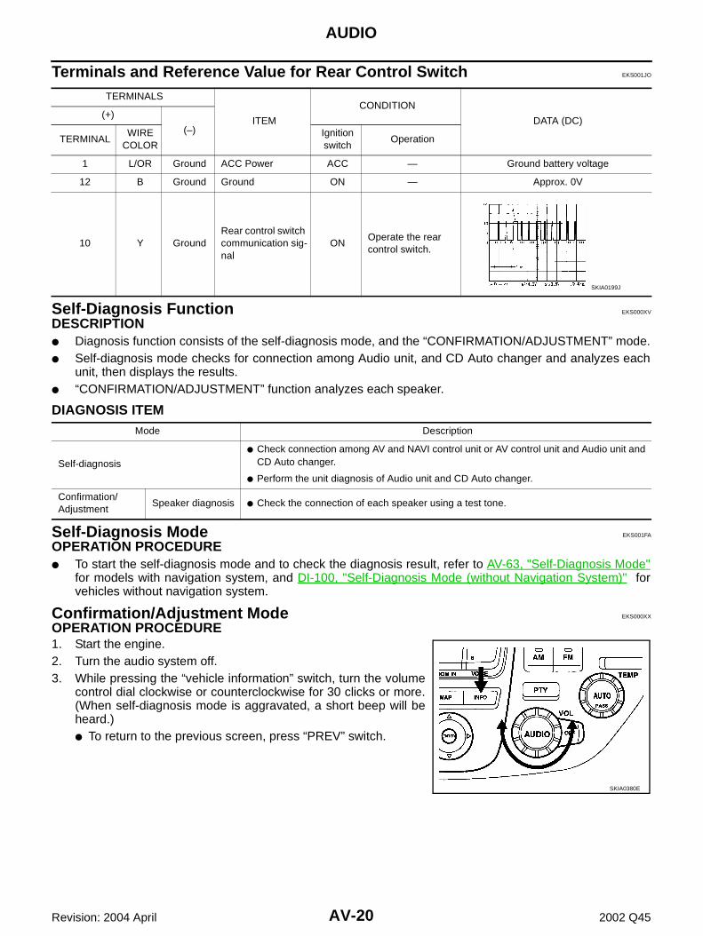
Terminals and Reference Value for Rear Control Switch EKS001JO
Self-Diagnosis Function EKS000XV
DESCRIPTION ● Diagnosis function consists of the self-diagnosis mode, and the “CONFIRMATION/ADJUSTMENT” mode.● Self-diagnosis mode checks for connection among Audio unit, and CD Auto changer and analyzes each
unit, then displays the results.● “CONFIRMATION/ADJUSTMENT” function analyzes each speaker.
DIAGNOSIS ITEM
Self-Diagnosis Mode EKS001FA
OPERATION PROCEDURE ● To start the self-diagnosis mode and to check the diagnosis result, refer to AV-63, "Self-Diagnosis Mode"
for models with navigation system, and DI-100, "Self-Diagnosis Mode (without Navigation System)" forvehicles without navigation system.
Confirmation/Adjustment Mode EKS000XX
OPERATION PROCEDURE 1. Start the engine.2. Turn the audio system off.3. While pressing the “vehicle information” switch, turn the volume
control dial clockwise or counterclockwise for 30 clicks or more.(When self-diagnosis mode is aggravated, a short beep will beheard.)● To return to the previous screen, press “PREV” switch.
TERMINALS
ITEM
CONDITION
DATA (DC)(+)
(–)TERMINAL
WIRE COLOR
Ignition switch
Operation
1 L/OR Ground ACC Power ACC — Ground battery voltage
12 B Ground Ground ON — Approx. 0V
10 Y GroundRear control switch communication sig-nal
ONOperate the rear control switch.
SKIA0199J
Mode Description
Self-diagnosis
● Check connection among AV and NAVI control unit or AV control unit and Audio unit and CD Auto changer.
● Perform the unit diagnosis of Audio unit and CD Auto changer.
Confirmation/Adjustment
Speaker diagnosis ● Check the connection of each speaker using a test tone.
SKIA0380E
AUDIO
AV-21
C
D
E
F
G
H
I
J
L
M
A
B
AV
Revision: 2004 April 2002 Q45
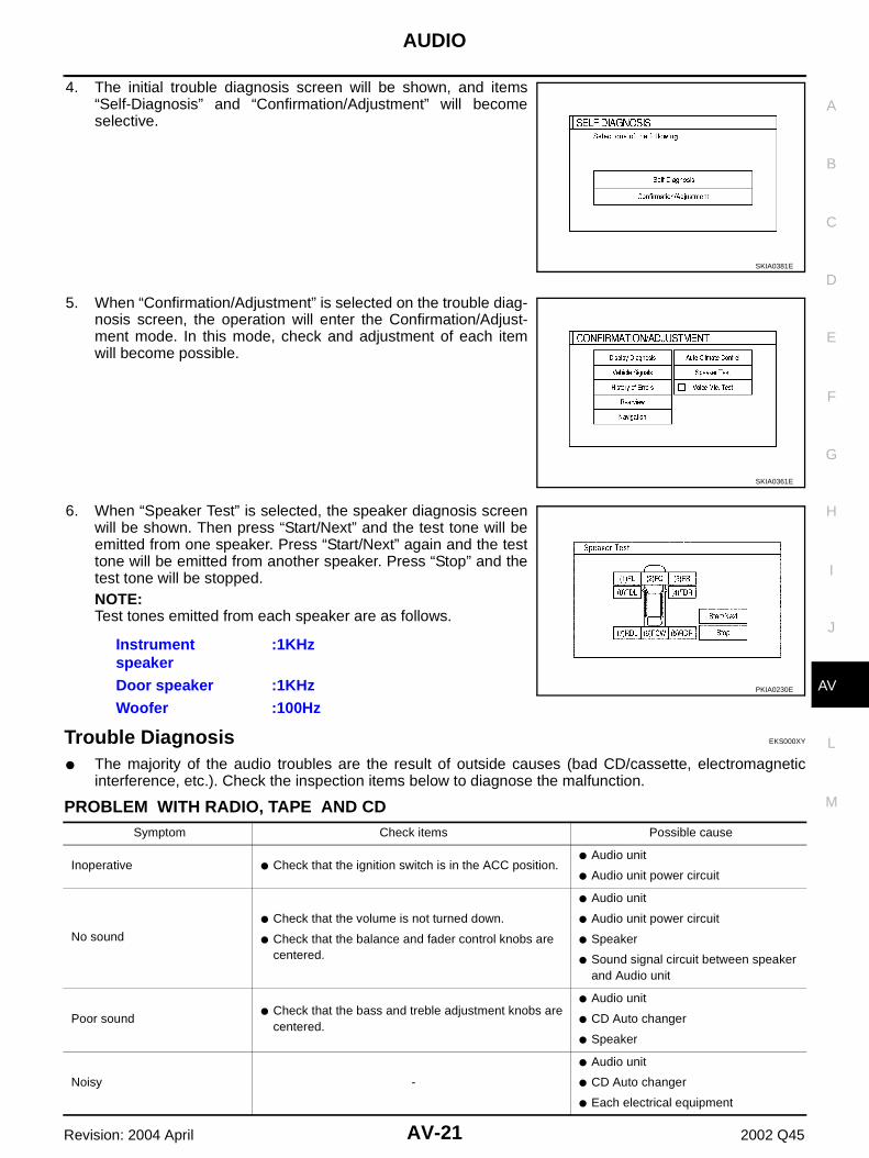
4. The initial trouble diagnosis screen will be shown, and items“Self-Diagnosis” and “Confirmation/Adjustment” will becomeselective.
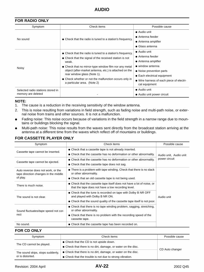
5. When “Confirmation/Adjustment” is selected on the trouble diag-nosis screen, the operation will enter the Confirmation/Adjust-ment mode. In this mode, check and adjustment of each itemwill become possible.
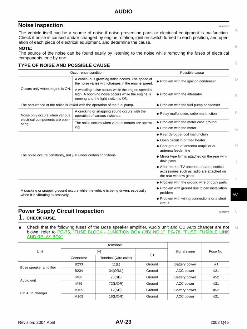
6. When “Speaker Test” is selected, the speaker diagnosis screenwill be shown. Then press “Start/Next” and the test tone will beemitted from one speaker. Press “Start/Next” again and the testtone will be emitted from another speaker. Press “Stop” and thetest tone will be stopped.NOTE:Test tones emitted from each speaker are as follows.
Trouble Diagnosis EKS000XY
● The majority of the audio troubles are the result of outside causes (bad CD/cassette, electromagneticinterference, etc.). Check the inspection items below to diagnose the malfunction.
PROBLEM WITH RADIO, TAPE AND CD
SKIA0381E
SKIA0361E
Instrument speaker
:1KHz
Door speaker :1KHzWoofer :100Hz
PKIA0230E
Symptom Check items Possible cause
Inoperative ● Check that the ignition switch is in the ACC position.● Audio unit
● Audio unit power circuit
No sound
● Check that the volume is not turned down.
● Check that the balance and fader control knobs are centered.
● Audio unit
● Audio unit power circuit
● Speaker
● Sound signal circuit between speaker and Audio unit
Poor sound● Check that the bass and treble adjustment knobs are
centered.
● Audio unit
● CD Auto changer
● Speaker
Noisy -
● Audio unit
● CD Auto changer
● Each electrical equipment
AV-22
AUDIO
Revision: 2004 April 2002 Q45
FOR RADIO ONLY
NOTE:1. The cause is a reduction in the receiving sensitivity of the window antenna.2. This is noise resulting from variations in field strength, such as fading noise and multi-path noise, or exter-
nal noise from trains and other sources. It is not a malfunction.● Fading noise: This noise occurs because of variations in the field strength in a narrow range due to moun-
tains or buildings blocking the signal.● Multi-path noise: This noise results from the waves sent directly from the broadcast station arriving at the
antenna at a different time from the waves which reflect off of mountains or buildings.
FOR CASSETTE PLAYER ONLY
FOR CD ONLY
Symptom Check items Possible cause
No sound ● Check that the radio is tuned to a station's frequency.
● Audio unit
● Antenna feeder
● Antenna amplifier
● Glass antenna
Noisy
● Check that the radio is tuned to a station's frequency.
● Check that the signal of the received station is not weak.
● Check that no mirror-type window film nor any metal object (after-market antenna, etc.) is attached on the rear window glass (Note 1).
● Check whether or not the malfunction occurs only in a particular area. (Note 2)
● Audio unit
● Antenna feeder
● Antenna amplifier
● window antenna
● Noise prevention parts
● Each electrical equipment
● Wire harness of each piece of electri-cal equipment
Selected radio stations stored in memory are deleted -
● Audio unit
● Audio unit power circuit
Symptom Check items Possible cause
Cassette tape cannot be inserted.● Check that a cassette tape is not already inserted.
● Check that the cassette has no deformation or other abnormality. Audio unit, Audio unit power circuit
Cassette tape cannot be ejected.● Check that the cassette has no deformation or other abnormality.
● Check that the cassette tape does not sag.
Auto reverse does not work, or the tape direction changes in the middle of play.
● There is a problem with tape winding. Check that there is no slack or other abnormality.
● Check that an old cassette tape is not being used.
Audio unit
There is much noise.● Check that the cassette tape itself does not have a lot of noise, or
that the tape does not have a low recording level.
The sound is not clear.
● Check that the tune is recorded on tape with Dolby B NR OFF and played with Dolby B NR ON.
● Check that the sound quality of the cassette tape itself is not poor.
Sound fluctuates/tape speed not cor-rect
● Check that there is no tape winding problem, sagging, stretching, or other abnormality.
● Check that there is no problem with the recording speed of the cassette tape.
No sound. ● Check that the cassette tape has been recorded on.
Symptom Check items Possible cause
The CD cannot be played.● Check that the CD is not upside down.
● Check that there is no dirt, damage, or water on the disc.CD Auto changer
The sound skips, stops suddenly, or is distorted.
● Check that there is no dirt, damage, or water on the disc.
● Check that the trouble is not due to strong vibration.
AUDIO
AV-23
C
D
E
F
G
H
I
J
L
M
A
B
AV
Revision: 2004 April 2002 Q45
Noise Inspection EKS000XZ
The vehicle itself can be a source of noise if noise prevention parts or electrical equipment is malfunction.Check if noise is caused and/or changed by engine rotation, ignition switch turned to each position, and oper-ation of each piece of electrical equipment, and determine the cause.NOTE:The source of the noise can be found easily by listening to the noise while removing the fuses of electricalcomponents, one by one.
TYPE OF NOISE AND POSSIBLE CAUSE
Power Supply Circuit Inspection EKS000Y0
1. CHECK FUSE.
● Check that the following fuses of the Bose speaker amplifier, Audio unit and CD Auto changer are notblown, refer to PG-75, "FUSE BLOCK - JUNCTION BOX (J/B) NO.1" .PG-78, "FUSE, FUSIBLE LINKAND RELAY BOX" .
Occurrence condition Possible cause
Occurs only when engine is ON.
A continuous growling noise occurs. The speed of the noise varies with changes in the engine speed.
● Problem with the ignition condenser.
A whistling noise occurs while the engine speed is high. A booming noise occurs while the engine is running and the light switch is ON.
● Problem with the alternator
The occurrence of the noise is linked with the operation of the fuel pump. ● Problem with the fuel pump condenser
Noise only occurs when various electrical components are oper-ating.
A cracking or snapping sound occurs with the operation of various switches.
● Relay malfunction, radio malfunction
The noise occurs when various motors are operat-ing.
● Problem with the motor case ground
● Problem with the motor
The noise occurs constantly, not just under certain conditions.
● Rear defogger coil malfunction
● Open circuit in printed heater
● Poor ground of antenna amplifier or antenna feeder line
● Mirror type film is attached on the rear win-dow glass.
● After-market TV antenna and/or electrical accessories such as radio are attached on the rear window glass.
A cracking or snapping sound occurs while the vehicle is being driven, especially when it is vibrating excessively.
● Problem with the ground wire of body parts
● Problem with ground due to part installation problem
● Problem with wiring connections or a short circuit
Unit
Terminals
Signal name Fuse No.(+)(-)
Connector Terminal (wire color)
Bose speaker amplifierB233 11(L) Ground Battery power #J
B234 34(OR/L) Ground ACC power #21
Audio unitM86 73(SB) Ground Battery power #52
M86 72(L/OR) Ground ACC power #21
CD Auto changerM109 12(SB) Ground Battery power #52
M109 16(L/OR) Ground ACC power #21
AV-24
AUDIO
Revision: 2004 April 2002 Q45
OK or NGOK >> GO TO 2.NG >> If fuse is blown be sure to eliminate cause of problem before installing new fuse. refer to PG-2,
"POWER SUPPLY ROUTING" .
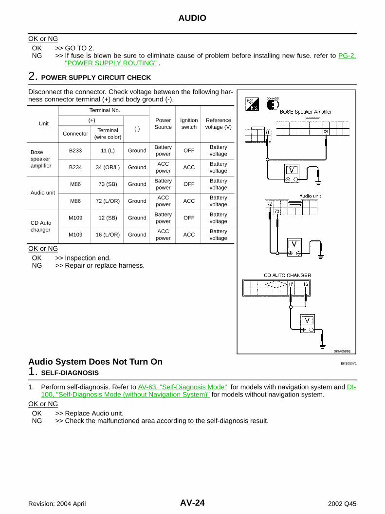
2. POWER SUPPLY CIRCUIT CHECK
Disconnect the connector. Check voltage between the following har-ness connector terminal (+) and body ground (-).
OK or NGOK >> Inspection end.NG >> Repair or replace harness.
Audio System Does Not Turn On EKS000Y1
1. SELF-DIAGNOSIS
1. Perform self-diagnosis. Refer to AV-63, "Self-Diagnosis Mode" for models with navigation system and DI-100, "Self-Diagnosis Mode (without Navigation System)" for models without navigation system.
OK or NGOK >> Replace Audio unit.NG >> Check the malfunctioned area according to the self-diagnosis result.
Unit
Terminal No.
Power Source
Ignition switch
Reference voltage (V)
(+)
(-)Connector
Terminal (wire color)
Bose speaker amplifier
B233 11 (L) GroundBattery power
OFFBattery voltage
B234 34 (OR/L) GroundACC
powerACC
Battery voltage
Audio unit
M86 73 (SB) GroundBattery power
OFFBattery voltage
M86 72 (L/OR) GroundACC
powerACC
Battery voltage
CD Auto changer
M109 12 (SB) GroundBattery power
OFFBattery voltage
M109 16 (L/OR) GroundACC
powerACC
Battery voltage
SKIA0589E
AUDIO
AV-25
C
D
E
F
G
H
I
J
L
M
A
B
AV
Revision: 2004 April 2002 Q45
Steering Switch Does Not Operate EKS001JP
1. SELF-DIAGNOSIS MODE OF MULTIFUNCTION SWITCH
1. Carry out the self-diagnosis mode in the self-diagnosis function. 2. Push steering switch.
OK or NGOK >> GO TO 2.NO >> GO TO 3.
2. SELF-DIAGNOSIS MODE OF AV COMMUNICATION LINE
1. Carry out the self-diagnosis mode in the self-diagnosis function.Refer to AV-63, "Self-Diagnosis Mode"(with navigation system) or refer to DI-100, "Self-Diagnosis Mode (without Navigation System)" .
Dose self–diagnosis start?YES >> With self-diagnosis results, check the malfunction part.NO >> ● Check multifunction switch of power supply and ground circuit check.Refer to DI-122, "Power
Supply and Ground Circuit Check for Multifunction Switch" .● Check harness between multifunction switch and AV and NAVI control unit or AV control unit.
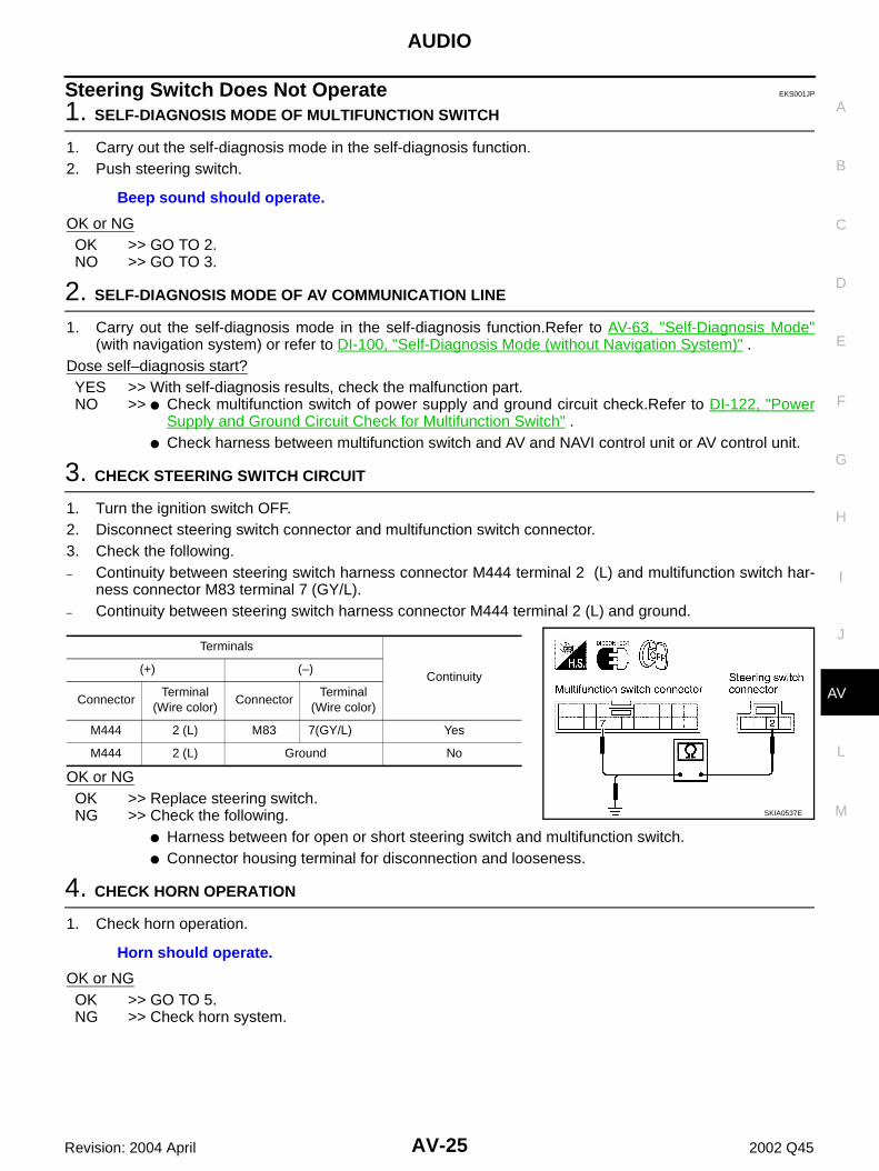
3. CHECK STEERING SWITCH CIRCUIT
1. Turn the ignition switch OFF.2. Disconnect steering switch connector and multifunction switch connector.3. Check the following.– Continuity between steering switch harness connector M444 terminal 2 (L) and multifunction switch har-
ness connector M83 terminal 7 (GY/L).– Continuity between steering switch harness connector M444 terminal 2 (L) and ground.
OK or NGOK >> Replace steering switch.NG >> Check the following.
● Harness between for open or short steering switch and multifunction switch.● Connector housing terminal for disconnection and looseness.
4. CHECK HORN OPERATION
1. Check horn operation.
OK or NGOK >> GO TO 5.NG >> Check horn system.
Beep sound should operate.
Terminals
Continuity(+) (–)
ConnectorTerminal
(Wire color)Connector
Terminal(Wire color)
M444 2 (L) M83 7(GY/L) Yes
M444 2 (L) Ground No
SKIA0537E
Horn should operate.
AV-26
AUDIO
Revision: 2004 April 2002 Q45
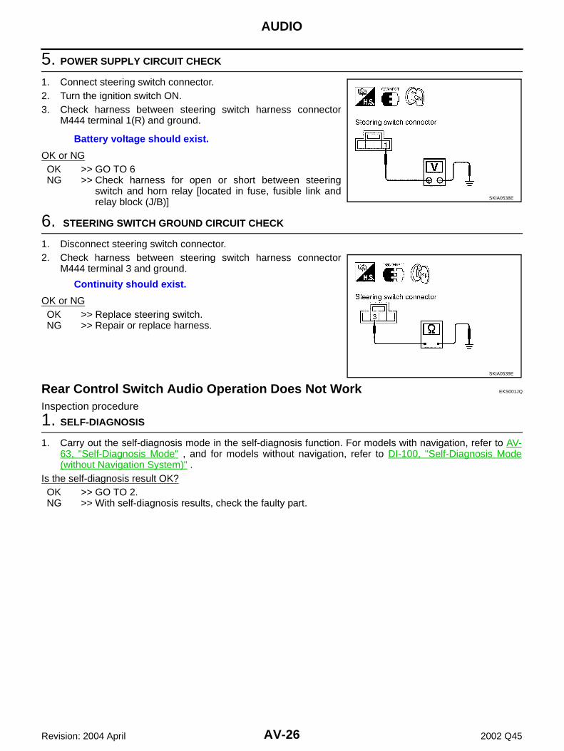
5. POWER SUPPLY CIRCUIT CHECK
1. Connect steering switch connector.2. Turn the ignition switch ON.3. Check harness between steering switch harness connector
M444 terminal 1(R) and ground.
OK or NGOK >> GO TO 6NG >> Check harness for open or short between steering
switch and horn relay [located in fuse, fusible link andrelay block (J/B)]
OK or NGOK >> Replace steering switch.NG >> Repair or replace harness.
Rear Control Switch Audio Operation Does Not Work EKS001JQ
Inspection procedure
1. SELF-DIAGNOSIS
1. Carry out the self-diagnosis mode in the self-diagnosis function. For models with navigation, refer to AV-63, "Self-Diagnosis Mode" , and for models without navigation, refer to DI-100, "Self-Diagnosis Mode(without Navigation System)" .
Is the self-diagnosis result OK?OK >> GO TO 2.NG >> With self-diagnosis results, check the faulty part.
Battery voltage should exist.
SKIA0538E
Continuity should exist.
SKIA0539E
AUDIO
AV-27
C
D
E
F
G
H
I
J
L
M
A
B
AV
Revision: 2004 April 2002 Q45
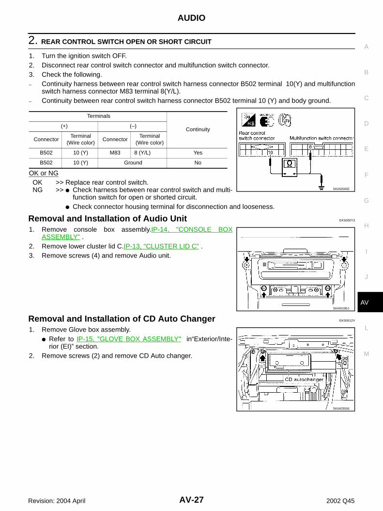
2. REAR CONTROL SWITCH OPEN OR SHORT CIRCUIT
1. Turn the ignition switch OFF.2. Disconnect rear control switch connector and multifunction switch connector.3. Check the following.– Continuity harness between rear control switch harness connector B502 terminal 10(Y) and multifunction
switch harness connector M83 terminal 8(Y/L). – Continuity between rear control switch harness connector B502 terminal 10 (Y) and body ground.
OK or NGOK >> Replace rear control switch.NG >> ● Check harness between rear control switch and multi-
function switch for open or shorted circuit.● Check connector housing terminal for disconnection and looseness.
Removal and Installation of Steering Wheel Switch EKS001HQ
SRS-34, "DRIVER AIR BAG MODULE".
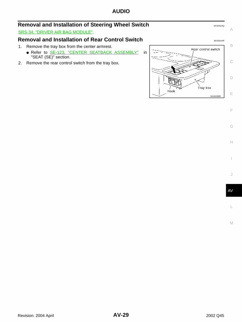
Removal and Installation of Rear Control Switch EKS001HR
1. Remove the tray box from the center armrest.● Refer to SE-123, "CENTER SEATBACK ASSEMBLY" in
"SEAT (SE)" section.2. Remove the rear control switch from the tray box.
SKIA0390E
AV-30
AUDIO ANTENNA
Revision: 2004 April 2002 Q45
AUDIO ANTENNA PFP:28200
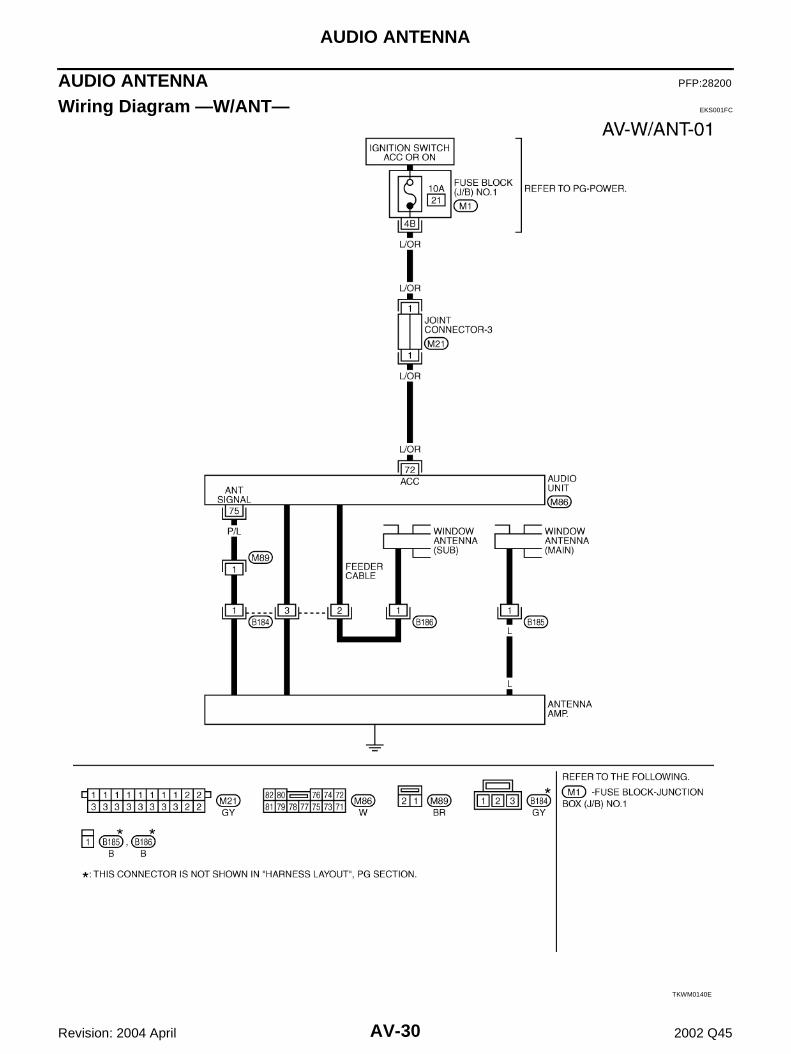
Wiring Diagram —W/ANT— EKS001FC
TKWM0140E
AUDIO ANTENNA
AV-31
C
D
E
F
G
H
I
J
L
M
A
B
AV
Revision: 2004 April 2002 Q45
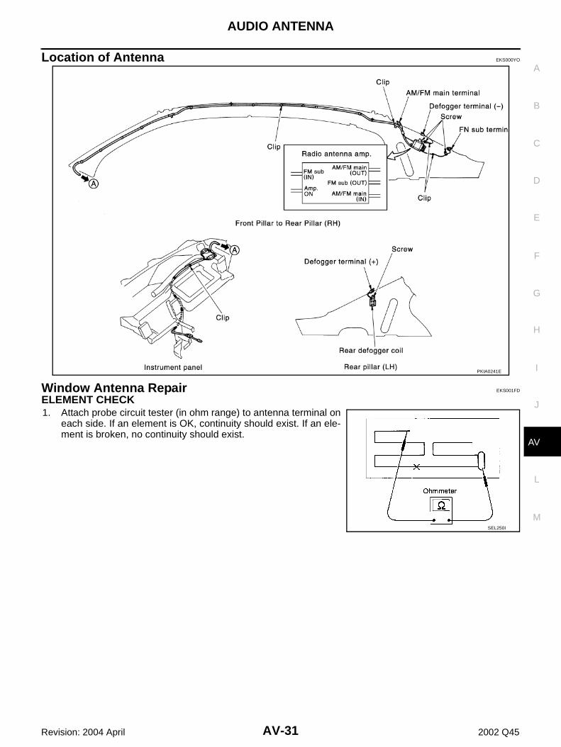
Location of Antenna EKS000YO
Window Antenna Repair EKS001FD
ELEMENT CHECK 1. Attach probe circuit tester (in ohm range) to antenna terminal on
each side. If an element is OK, continuity should exist. If an ele-ment is broken, no continuity should exist.
PKIA0241E
SEL250I
AV-32
TELEPHONE (PRE WIRE)
Revision: 2004 April 2002 Q45
TELEPHONE (PRE WIRE) PFP:28342
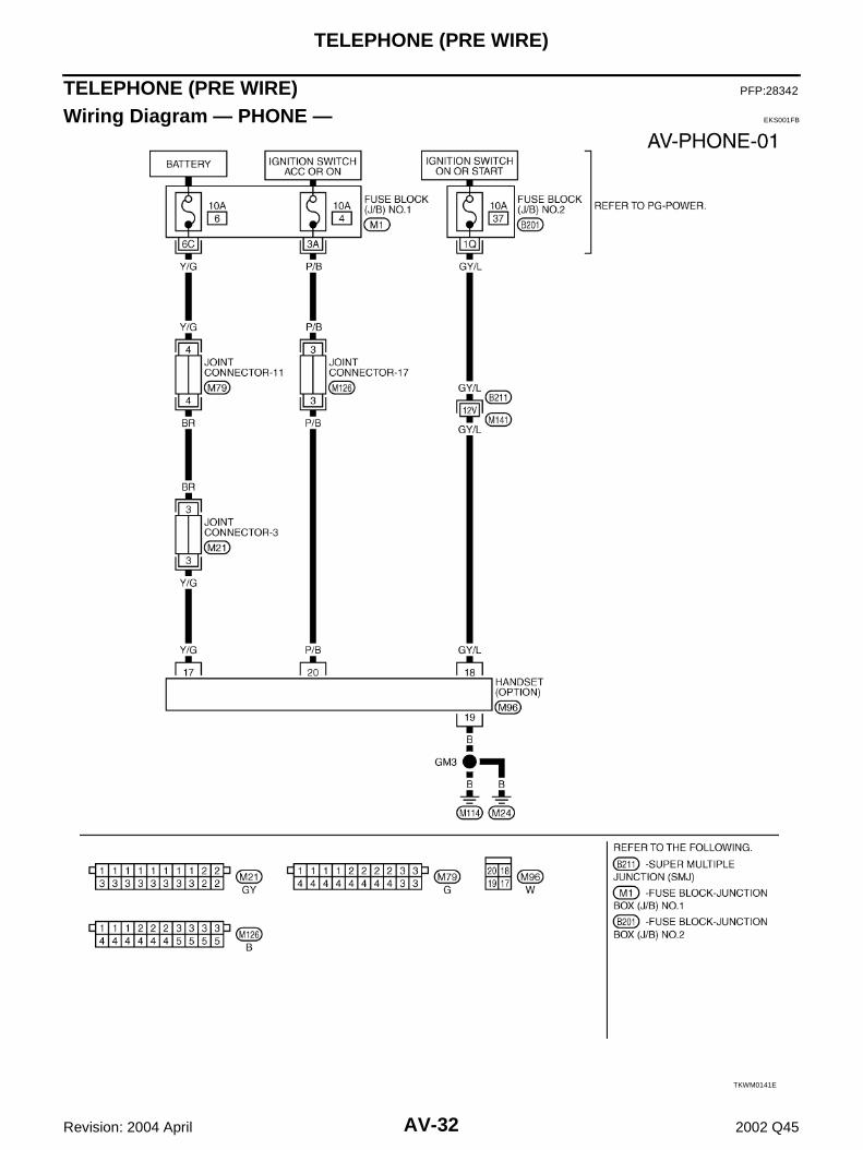
Wiring Diagram — PHONE — EKS001FB
TKWM0141E
NAVIGATION SYSTEM
AV-33
C
D
E
F
G
H
I
J
L
M
A
B
AV
Revision: 2004 April 2002 Q45
NAVIGATION SYSTEM PFP:25915
System Description EKS001LN
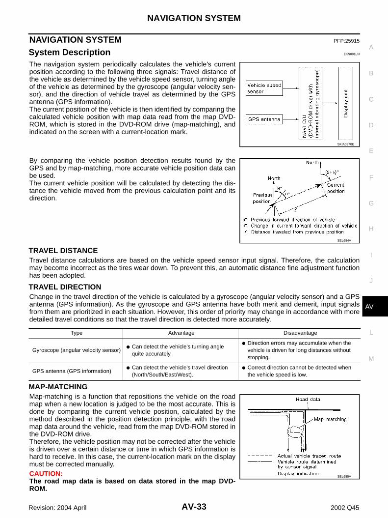
The navigation system periodically calculates the vehicle's currentposition according to the following three signals: Travel distance ofthe vehicle as determined by the vehicle speed sensor, turning angleof the vehicle as determined by the gyroscope (angular velocity sen-sor), and the direction of vehicle travel as determined by the GPSantenna (GPS information).The current position of the vehicle is then identified by comparing thecalculated vehicle position with map data read from the map DVD-ROM, which is stored in the DVD-ROM drive (map-matching), andindicated on the screen with a current-location mark.
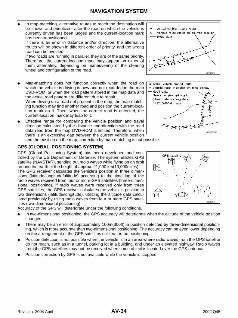
By comparing the vehicle position detection results found by theGPS and by map-matching, more accurate vehicle position data canbe used.The current vehicle position will be calculated by detecting the dis-tance the vehicle moved from the previous calculation point and itsdirection.
TRAVEL DISTANCE Travel distance calculations are based on the vehicle speed sensor input signal. Therefore, the calculationmay become incorrect as the tires wear down. To prevent this, an automatic distance fine adjustment functionhas been adopted.
TRAVEL DIRECTION Change in the travel direction of the vehicle is calculated by a gyroscope (angular velocity sensor) and a GPSantenna (GPS information). As the gyroscope and GPS antenna have both merit and demerit, input signalsfrom them are prioritized in each situation. However, this order of priority may change in accordance with moredetailed travel conditions so that the travel direction is detected more accurately.
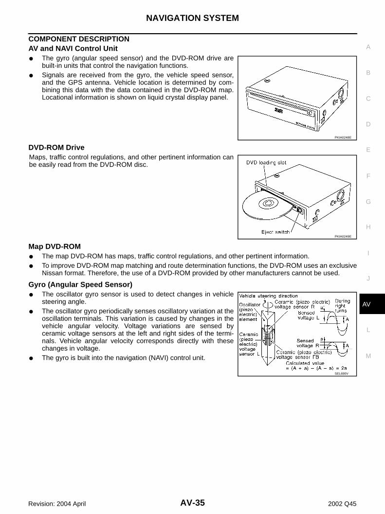
MAP-MATCHINGMap-matching is a function that repositions the vehicle on the roadmap when a new location is judged to be the most accurate. This isdone by comparing the current vehicle position, calculated by themethod described in the position detection principle, with the roadmap data around the vehicle, read from the map DVD-ROM stored inthe DVD-ROM drive.Therefore, the vehicle position may not be corrected after the vehicleis driven over a certain distance or time in which GPS information ishard to receive. In this case, the current-location mark on the displaymust be corrected manually.CAUTION:The road map data is based on data stored in the map DVD-ROM.
SKIA0370E
SEL684V
Type Advantage Disadvantage
Gyroscope (angular velocity sensor)● Can detect the vehicle's turning angle
quite accurately.
● Direction errors may accumulate when the vehicle is driven for long distances without stopping.
GPS antenna (GPS information)● Can detect the vehicle's travel direction
(North/South/East/West).● Correct direction cannot be detected when
the vehicle speed is low.
SEL685V
AV-34
NAVIGATION SYSTEM
Revision: 2004 April 2002 Q45
● In map-matching, alternative routes to reach the destination willbe shown and prioritized, after the road on which the vehicle iscurrently driven has been judged and the current-location markhas been repositioned.If there is an error in distance and/or direction, the alternativeroutes will be shown in different order of priority, and the wrongroad can be avoided.If two roads are running in parallel, they are of the same priority.Therefore, the current-location mark may appear on either ofthem alternately, depending on maneuvering of the steeringwheel and configuration of the road.
● Map-matching does not function correctly when the road onwhich the vehicle is driving is new and not recorded in the mapDVD-ROM, or when the road pattern stored in the map data andthe actual road pattern are different due to repair.When driving on a road not present in the map, the map-match-ing function may find another road and position the current-loca-tion mark on it. Then, when the correct road is detected, thecurrent-location mark may leap to it.
● Effective range for comparing the vehicle position and traveldirection calculated by the distance and direction with the roaddata read from the map DVD-ROM is limited. Therefore, whenthere is an excessive gap between the current vehicle positionand the position on the map, correction by map-matching is not possible.
GPS (GLOBAL POSITIONING SYSTEM)GPS (Global Positioning System) has been developed and con-trolled by the US Department of Defense. The system utilizes GPSsatellite (NAVSTAR), sending out radio waves while flying on an orbitaround the earth at the height of approx. 21,000 km(13,000miles).The GPS receiver calculates the vehicle's position in three dimen-sions (latitude/longitude/altitude) according to the time lag of theradio waves received from four or more GPS satellites (three-dimen-sional positioning). If radio waves were received only from threeGPS satellites, the GPS receiver calculates the vehicle's position intwo dimensions (latitude/longitude), utilizing the altitude data calcu-lated previously by using radio waves from four or more GPS satel-lites (two-dimensional positioning).Accuracy of the GPS will deteriorate under the following conditions.● In two-dimensional positioning, the GPS accuracy will deteriorate when the altitude of the vehicle position
changes.● There may be an error of approximately 100m(300ft) in position detected by three-dimensional position-
ing, which is more accurate than two-dimensional positioning. The accuracy can be even lower dependingon the arrangement of the GPS satellites utilized for the positioning.
● Position detection is not possible when the vehicle is in an area where radio waves from the GPS satellitedo not reach, such as in a tunnel, parking lot in a building, and under an elevated highway. Radio wavesfrom the GPS satellites may not be received when some object is located over the GPS antenna.
● Position correction by GPS is not available while the vehicle is stopped.
SEL686V
SKIA0613E
SEL526V
NAVIGATION SYSTEM
AV-35
C
D
E
F
G
H
I
J
L
M
A
B
AV
Revision: 2004 April 2002 Q45
COMPONENT DESCRIPTION AV and NAVI Control Unit● The gyro (angular speed sensor) and the DVD-ROM drive are
built-in units that control the navigation functions.● Signals are received from the gyro, the vehicle speed sensor,
and the GPS antenna. Vehicle location is determined by com-bining this data with the data contained in the DVD-ROM map.Locational information is shown on liquid crystal display panel.
DVD-ROM DriveMaps, traffic control regulations, and other pertinent information canbe easily read from the DVD-ROM disc.
Map DVD-ROM● The map DVD-ROM has maps, traffic control regulations, and other pertinent information.● To improve DVD-ROM map matching and route determination functions, the DVD-ROM uses an exclusive
Nissan format. Therefore, the use of a DVD-ROM provided by other manufacturers cannot be used.
Gyro (Angular Speed Sensor)● The oscillator gyro sensor is used to detect changes in vehicle
steering angle.● The oscillator gyro periodically senses oscillatory variation at the
oscillation terminals. This variation is caused by changes in thevehicle angular velocity. Voltage variations are sensed byceramic voltage sensors at the left and right sides of the termi-nals. Vehicle angular velocity corresponds directly with thesechanges in voltage.
● The gyro is built into the navigation (NAVI) control unit.
PKIA0248E
PKIA0249E
SEL690V
AV-36
NAVIGATION SYSTEM
Revision: 2004 April 2002 Q45
BIRD VIEW™
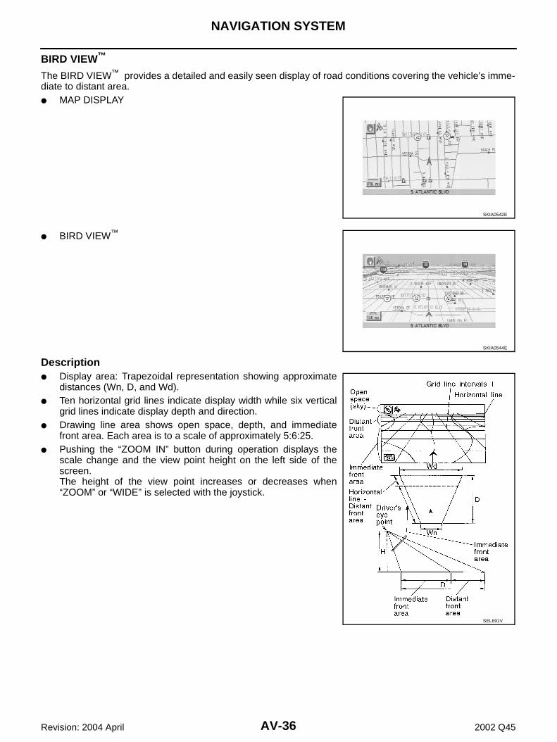
The BIRD VIEW™ provides a detailed and easily seen display of road conditions covering the vehicle's imme-diate to distant area.● MAP DISPLAY
distances (Wn, D, and Wd).● Ten horizontal grid lines indicate display width while six vertical
grid lines indicate display depth and direction.● Drawing line area shows open space, depth, and immediate
front area. Each area is to a scale of approximately 5:6:25.● Pushing the “ZOOM IN” button during operation displays the
scale change and the view point height on the left side of thescreen.The height of the view point increases or decreases when“ZOOM” or “WIDE” is selected with the joystick.
SKIA0542E
SKIA0544E
SEL691V
NAVIGATION SYSTEM
AV-37
C
D
E
F
G
H
I
J
L
M
A
B
AV
Revision: 2004 April 2002 Q45
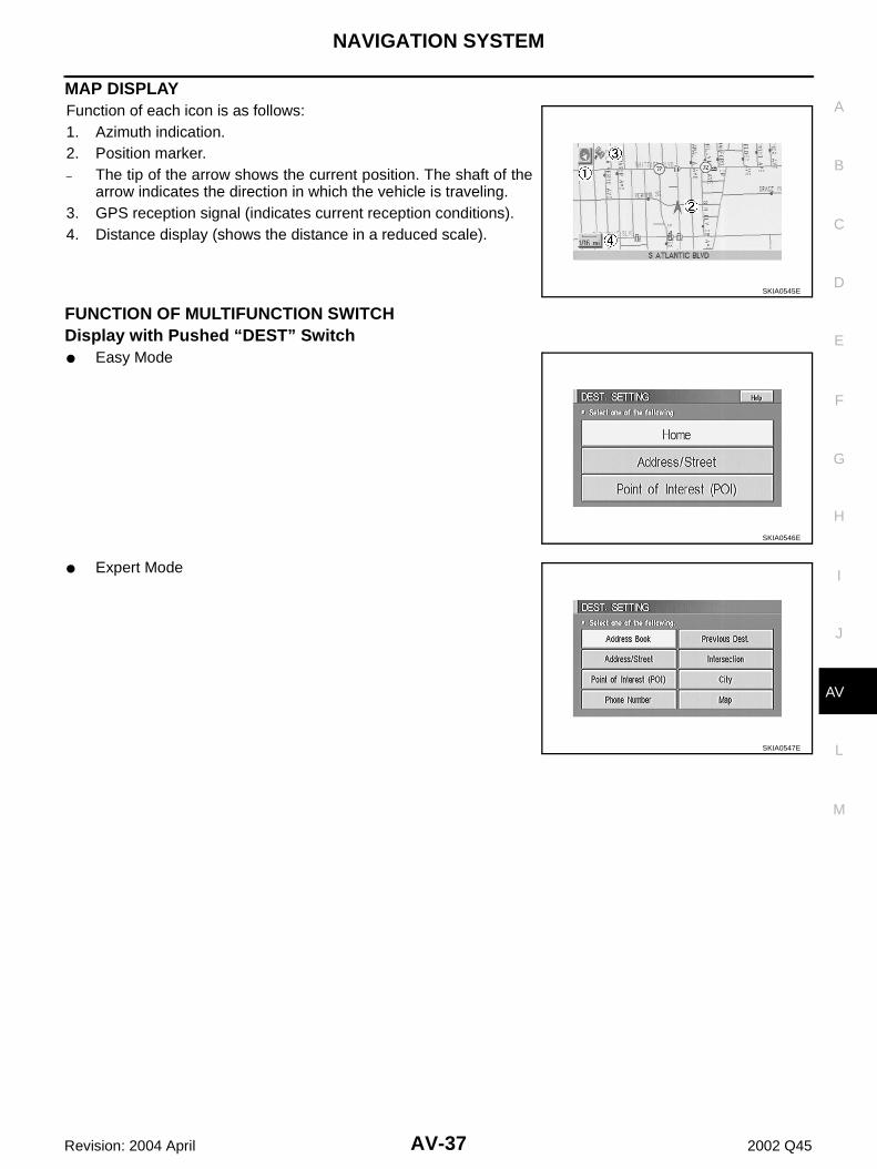
MAP DISPLAY Function of each icon is as follows:1. Azimuth indication.2. Position marker.– The tip of the arrow shows the current position. The shaft of the
arrow indicates the direction in which the vehicle is traveling.3. GPS reception signal (indicates current reception conditions).4. Distance display (shows the distance in a reduced scale).
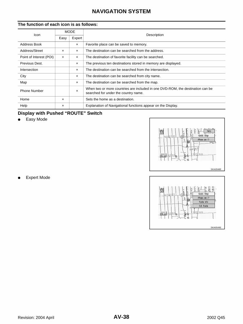
FUNCTION OF MULTIFUNCTION SWITCH Display with Pushed “DEST” Switch● Easy Mode
● Expert Mode
SKIA0545E
SKIA0546E
SKIA0547E
AV-38
NAVIGATION SYSTEM
Revision: 2004 April 2002 Q45
The function of each icon is as follows:
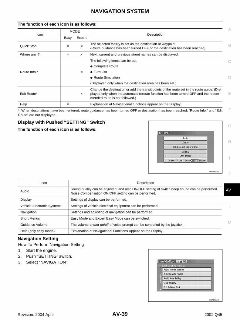
Display with Pushed “ROUTE” Switch● Easy Mode
● Expert Mode
IconMODE
DescriptionEasy Expert
Address Book × Favorite place can be saved to memory.
Address/Street × × The destination can be searched from the address.
Point of Interest (POI) × × The destination of favorite facility can be searched.
Previous Dest. × The previous ten destinations stored in memory are displayed.
Intersection × The destination can be searched from the intersection.
City × The destination can be searched from city name.
Map × The destination can be searched from the map.
Phone Number × When two or more countries are included in one DVD-ROM, the destination can be searched for under the country name.
Home × Sets the home as a destination.
Help × Explanation of Navigational functions appear on the Display.
SKIA0548E
SKIA0549E
NAVIGATION SYSTEM
AV-39
C
D
E
F
G
H
I
J
L
M
A
B
AV
Revision: 2004 April 2002 Q45
The function of each icon is as follows:
*: When destinations have been entered, route guidance has been turned OFF or destination has been reached, “Route Info.” and “EditRoute” are not displayed.
Display with Pushed “SETTING” Switch
The function of each icon is as follows:
Navigation SettingHow To Perform Navigation Setting1. Start the engine.2. Push “SETTING” switch.3. Select “NAVIGATION”.
IconMODE
DescriptionEasy Expert
Quick Stop × × The selected facility is set as the destination or waypoint.(Route guidance has been turned OFF or the destination has been reached)
Where am I? × × Next, current and previous street names can be displayed.
Route Info.* ×
The following items can be set.
● Complete Route
● Turn List
● Route Simulation
(Displayed only when the destination area has been set.)
Edit Route* ×Change the destination or add the transit points of the route set in the route guide. (Dis-played only when the automatic reroute function has been turned OFF and the recom-mended route is not followed.)
Help × Explanation of Navigational functions appear on the Display.
SKIA0550E
Icon Description
AudioSound quality can be adjusted, and also ON/OFF setting of switch beep sound can be performed.Noise Compensation ON/OFF setting can be performed.
Display Settings of display can be performed.
Vehicle Electronic Systems Settings of vehicle electrical equipment can be performed.
Navigation Settings and adjusting of navigation can be performed.
Short Menus Easy Mode and Expert Easy Mode can be switched.
Guidance Volume The volume and/or on/off of voice prompt can be controlled by the joystick.
Help (only easy mode) Explanation of Navigational Functions Appear on the Display.
SKIA0551E
AV-40
NAVIGATION SYSTEM
Revision: 2004 April 2002 Q45
Application Items
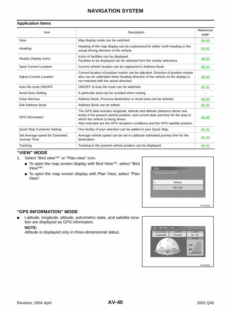
“VIEW” MODE1. Select “Bird view™” or “Plan view” icon.
● To open the map screen display with Bird View™, select “BirdView™”.
● To open the map screen display with Plan View, select “PlanView”.
tion are displayed as GPS information.NOTE:Altitude is displayed only in three-dimensional status.
Icon DescriptionReference
page
View Map display mode can be switched. AV-40
HeadingHeading of the map display can be customized for either north heading or the actual driving direction of the vehicle.
AV-42
Nearby Display IconsIcons of facilities can be displayed.Facilities to be displayed can be selected from the variety selections.
AV-42
Save Current Location Current vehicle location can be registered in Address Book. AV-41
Adjust Current LocationCurrent location of position marker can be adjusted. Direction of position marker also can be calibrated when heading direction of the vehicle on the display is not matched with the actual direction.
AV-42
Auto Re-route ON/OFF ON/OFF of Auto Re-route can be switched. AV-41
Avoid Area Setting A particular area can be avoided when routing. -
Clear Memory Address Book, Previous destination or Avoid area can be deleted. AV-43
Edit Address Book Address Book can be edited. AV-42
GPS Information
The GPS data includes longitude, latitude and altitude (distance above sea level) of the present vehicle position, and current date and time for the area in which the vehicle is being driven.Also indicated are the GPS reception conditions and the GPS satellite position.
AV-40
Quick Stop Customer Setting One facility of your selection can be added to your Quick Stop. AV-41
Set Average speed for Estimated Journey Time
Average vehicle speed can be set to calibrate estimated journey time for the destination.
AV-43
Tracking Tracking to the present vehicle position can be displayed. AV-41
SKIA0554E
SKIA0555E
NAVIGATION SYSTEM
AV-41
C
D
E
F
G
H
I
J
L
M
A
B
AV
Revision: 2004 April 2002 Q45
“SAVE CURRENT LOCATION” MODE● The current vehicle location can be registered in “Address
Book”.NOTE:“Address Book” can store 50 items max.
“QUICK STOP CUSTOMER SETTING” MODE● Select a category for the “Quick Stop” menu.
“AUTO RE-ROUTE” MODE● To Perform the auto re-route of route, select “ON”.● Not to Perform the auto re-route of route, select “OFF”.
“TRACKING” MODE● To leave no trail on the map, select “Off”.● To leave a trail in the map, select “On”.NOTE:When a trail display is turned OFF, trail data is erased from the mem-ory.
SKIA0556E
SKIA0557E
SKIA0558E
SKIA0559E
AV-42
NAVIGATION SYSTEM
Revision: 2004 April 2002 Q45
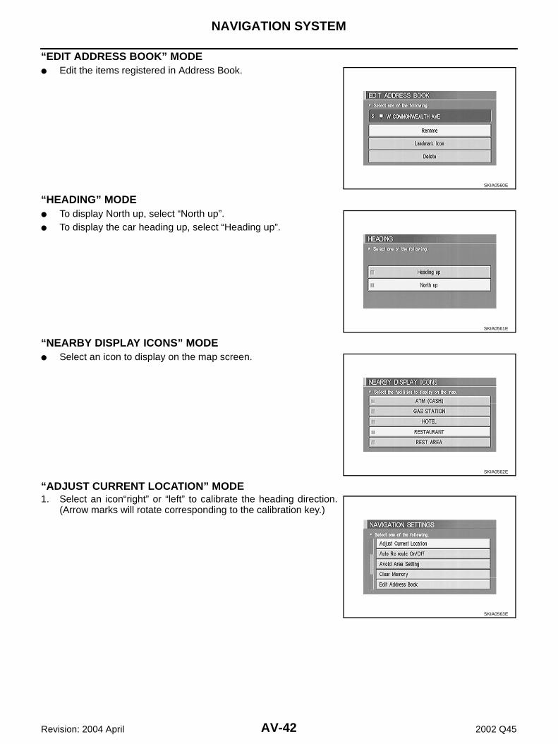
“EDIT ADDRESS BOOK” MODE● Edit the items registered in Address Book.
“HEADING” MODE● To display North up, select “North up”.● To display the car heading up, select “Heading up”.
“NEARBY DISPLAY ICONS” MODE● Select an icon to display on the map screen.
“ADJUST CURRENT LOCATION” MODE1. Select an icon“right” or “left” to calibrate the heading direction.
(Arrow marks will rotate corresponding to the calibration key.)
SKIA0560E
SKIA0561E
SKIA0562E
SKIA0563E
NAVIGATION SYSTEM
AV-43
C
D
E
F
G
H
I
J
L
M
A
B
AV
Revision: 2004 April 2002 Q45
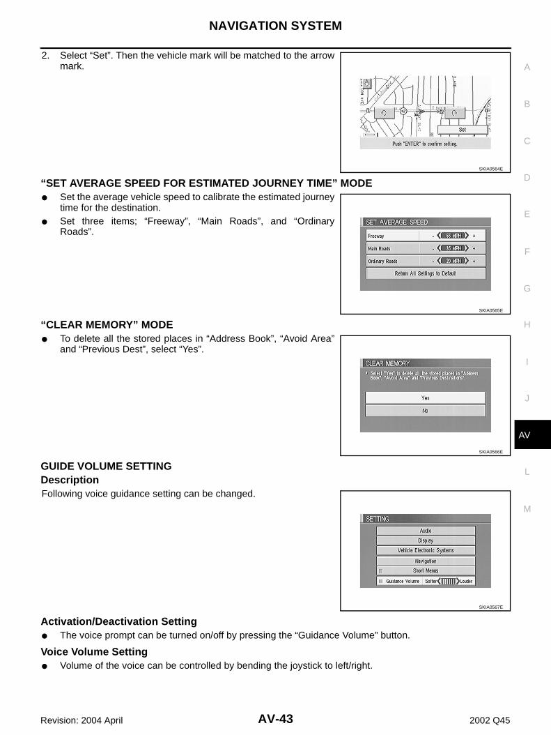
2. Select “Set”. Then the vehicle mark will be matched to the arrowmark.
“SET AVERAGE SPEED FOR ESTIMATED JOURNEY TIME” MODE● Set the average vehicle speed to calibrate the estimated journey
time for the destination.● Set three items; “Freeway”, “Main Roads”, and “Ordinary
Roads”.
“CLEAR MEMORY” MODE● To delete all the stored places in “Address Book”, “Avoid Area”
and “Previous Dest”, select “Yes”.
GUIDE VOLUME SETTING DescriptionFollowing voice guidance setting can be changed.
Activation/Deactivation Setting● The voice prompt can be turned on/off by pressing the “Guidance Volume” button.
Voice Volume Setting● Volume of the voice can be controlled by bending the joystick to left/right.
SKIA0564E
SKIA0565E
SKIA0566E
SKIA0567E
AV-44
NAVIGATION SYSTEM
Revision: 2004 April 2002 Q45
Precautions for AV and NAVI Control Unit Replacement EKS001LO
● When replacing the AV and NAVI control unit, eject the map DVD-ROM before disconnecting the battery.● The AV and NAVI control unit has the following information stored in its memory. Record the memory con-
tents before replacing the control unit, and input them in the new unit as necessary.
NOTE:Only removing the battery does not erase the memory.
<FM·AM> ● Preset frequency● Area for indicating station, selection of overlapped stations
<CD> ● Program status<Sound quality> ● Volume balance memory set values
● Equalizer memory set values<Image quality> ● Brightness of light when ON/OFF
● Current position● Destination, passing point 1 - 5● Registered places, their names, etc.
NAVIGATION SYSTEM
AV-45
C
D
E
F
G
H
I
J
L
M
A
B
AV
Revision: 2004 April 2002 Q45
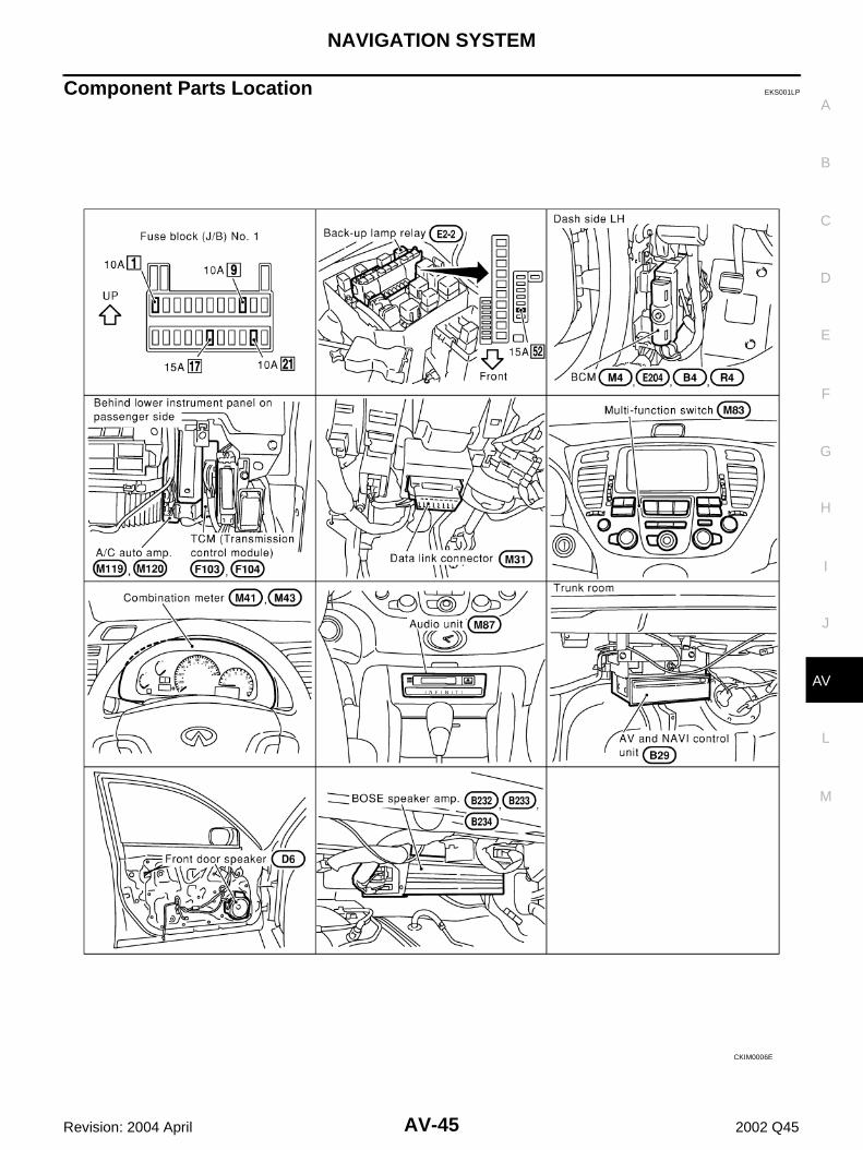
Component Parts Location EKS001LP
CKIM0006E
AV-46
NAVIGATION SYSTEM
Revision: 2004 April 2002 Q45
Location of Antenna EKS001LQ
Refer to AV-31, "Location of Antenna" .
NAVIGATION SYSTEM
AV-47
C
D
E
F
G
H
I
J
L
M
A
B
AV
Revision: 2004 April 2002 Q45
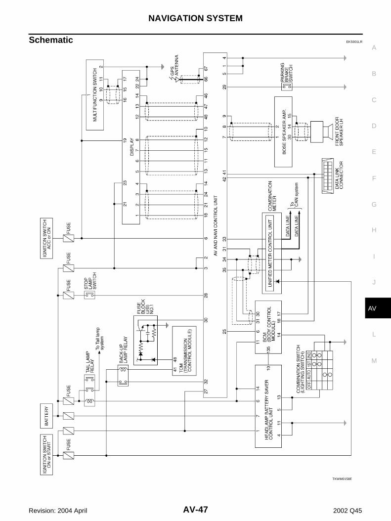
Schematic EKS001LR
TKWM0158E
AV-48
NAVIGATION SYSTEM
Revision: 2004 April 2002 Q45
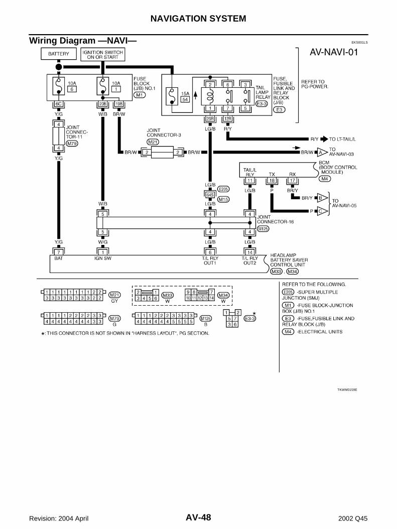
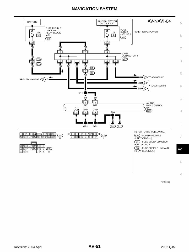
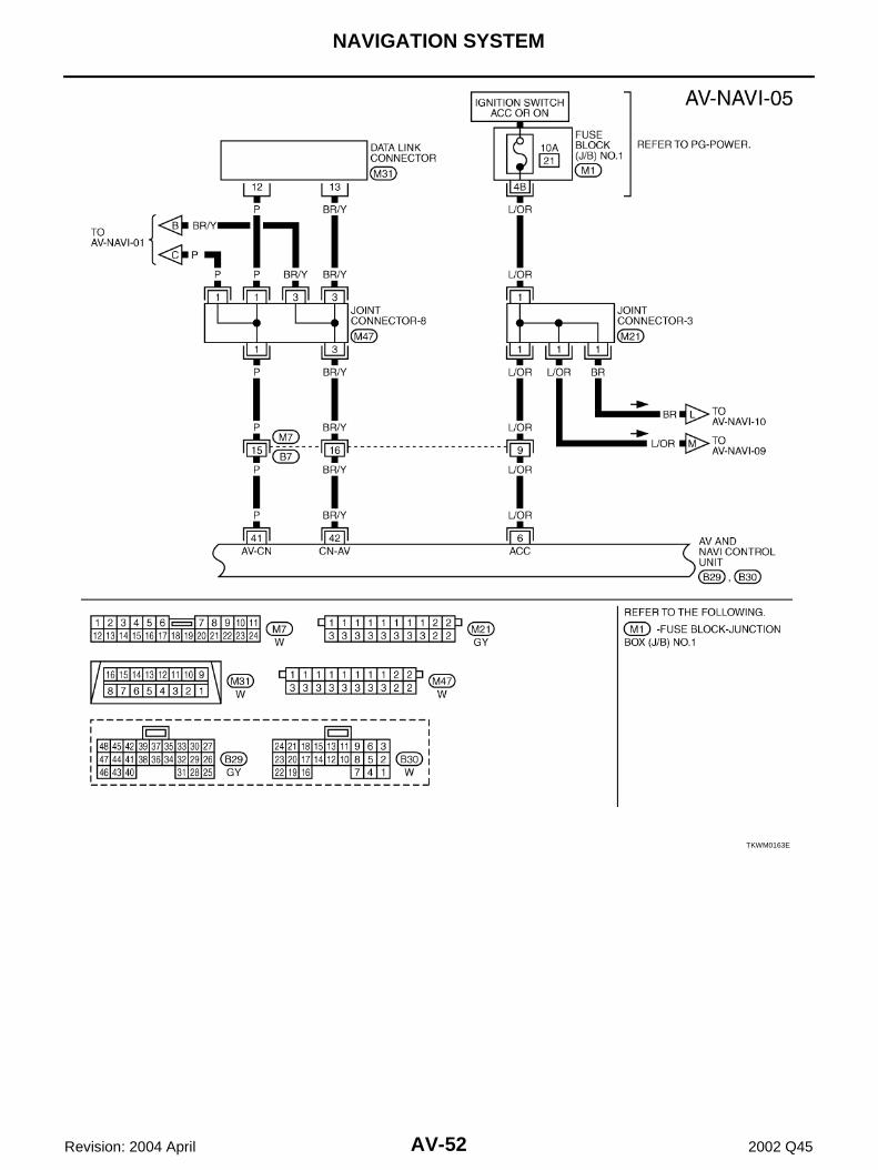
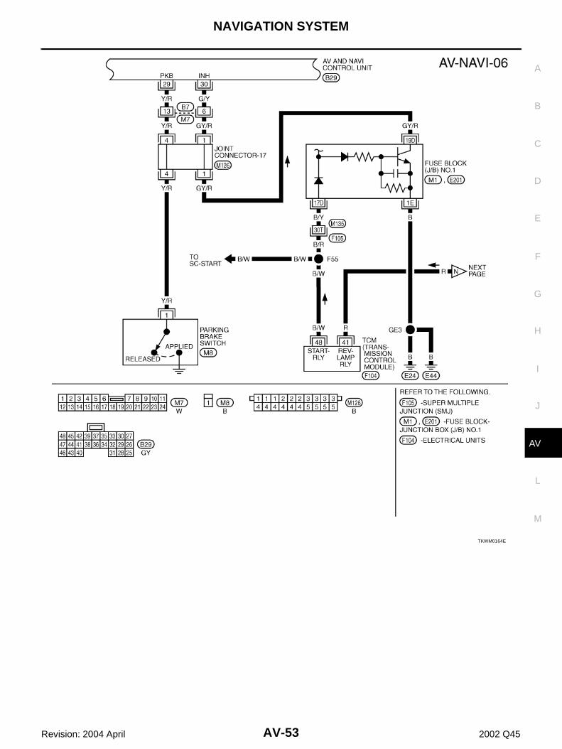
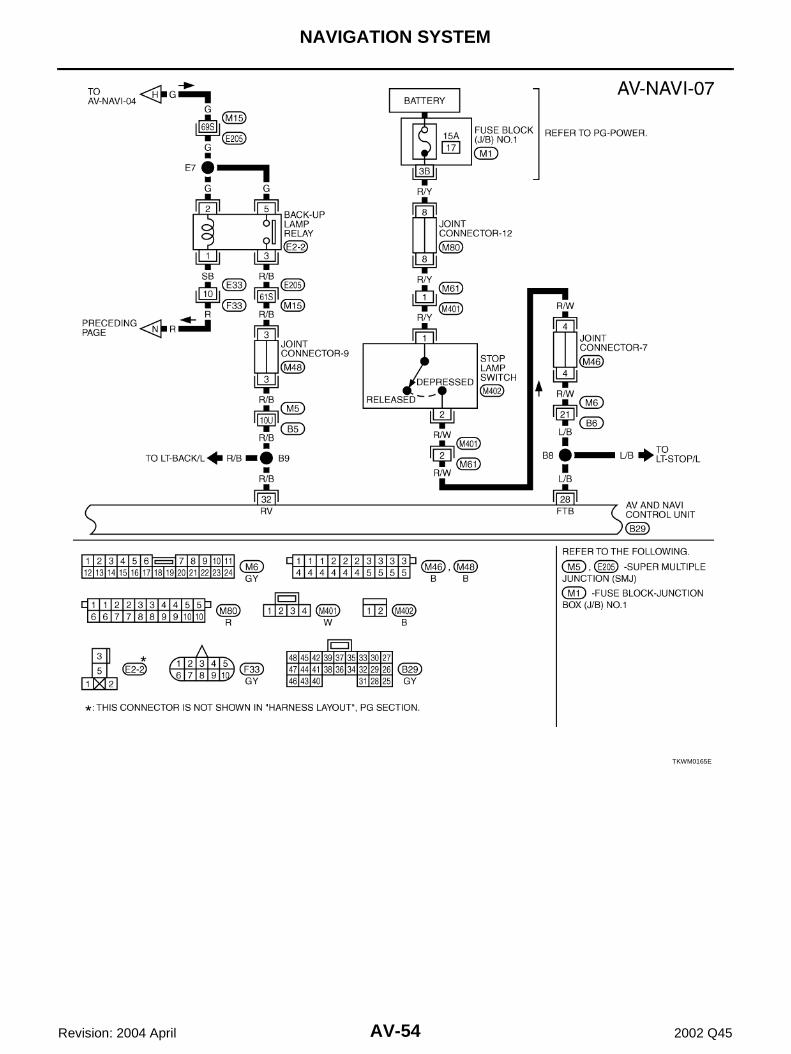
Wiring Diagram —NAVI— EKS001LS
TKWM0159E
NAVIGATION SYSTEM
AV-49
C
D
E
F
G
H
I
J
L
M
A
B
AV
Revision: 2004 April 2002 Q45
TKWM0160E
AV-50
NAVIGATION SYSTEM
Revision: 2004 April 2002 Q45
TKWM0161E
NAVIGATION SYSTEM
AV-51
C
D
E
F
G
H
I
J
L
M
A
B
AV
Revision: 2004 April 2002 Q45
TKWM0162E
AV-52
NAVIGATION SYSTEM
Revision: 2004 April 2002 Q45
TKWM0163E
NAVIGATION SYSTEM
AV-53
C
D
E
F
G
H
I
J
L
M
A
B
AV
Revision: 2004 April 2002 Q45
TKWM0164E
AV-54
NAVIGATION SYSTEM
Revision: 2004 April 2002 Q45
TKWM0165E
NAVIGATION SYSTEM
AV-55
C
D
E
F
G
H
I
J
L
M
A
B
AV
Revision: 2004 April 2002 Q45
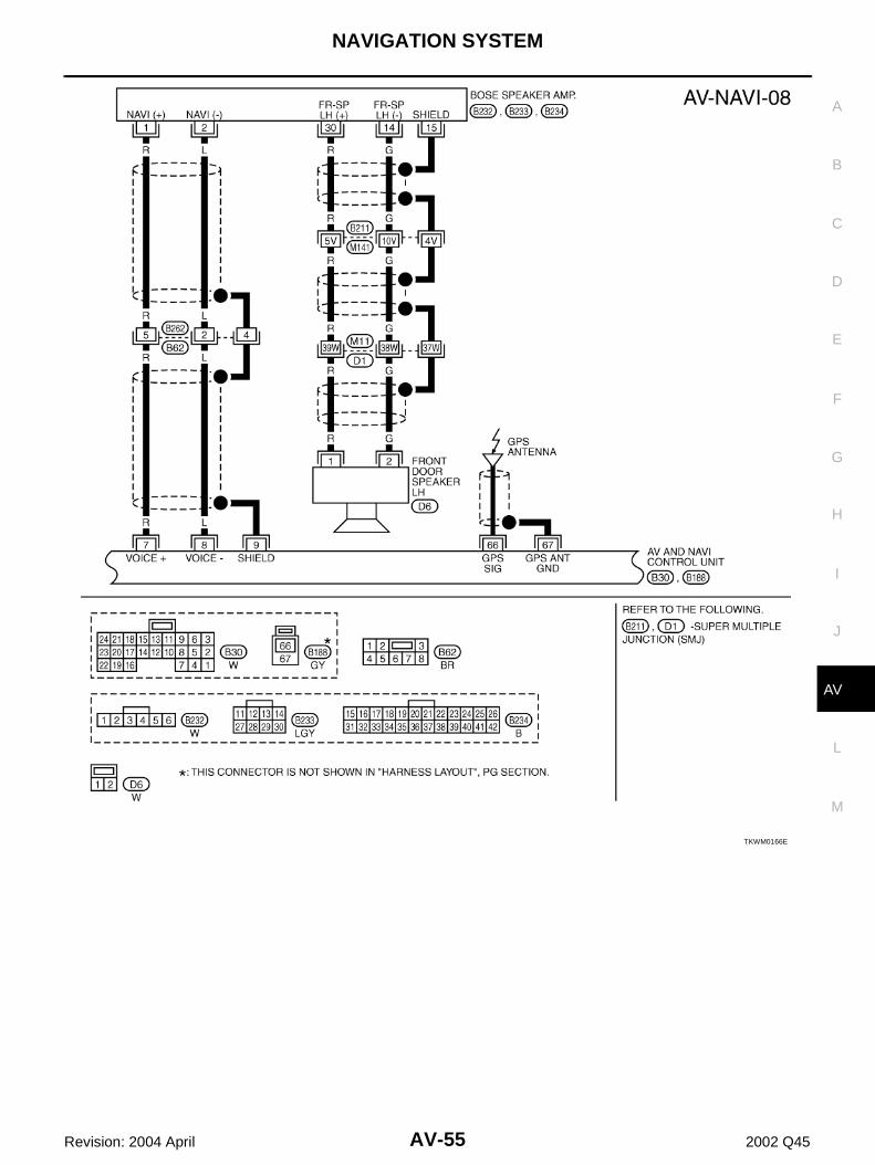
TKWM0166E
AV-56
NAVIGATION SYSTEM
Revision: 2004 April 2002 Q45
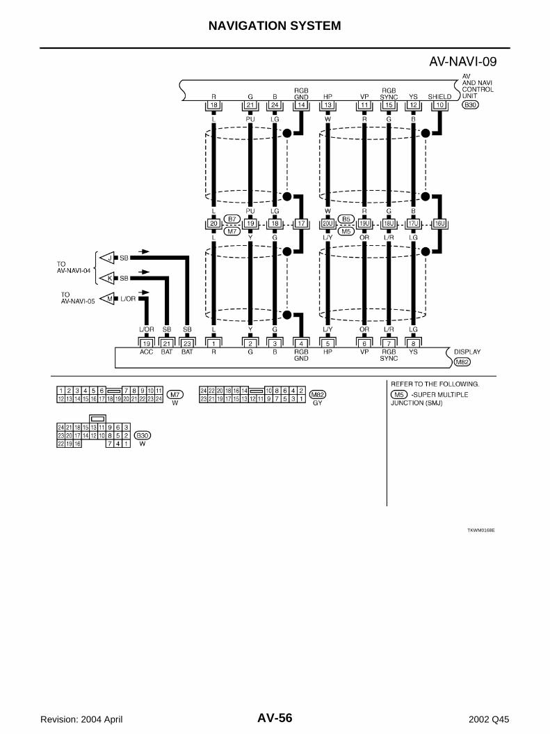
TKWM0168E
NAVIGATION SYSTEM
AV-57
C
D
E
F
G
H
I
J
L
M
A
B
AV
Revision: 2004 April 2002 Q45
Terminals and Reference Value for AV and NAVI Control unit EKS001LT
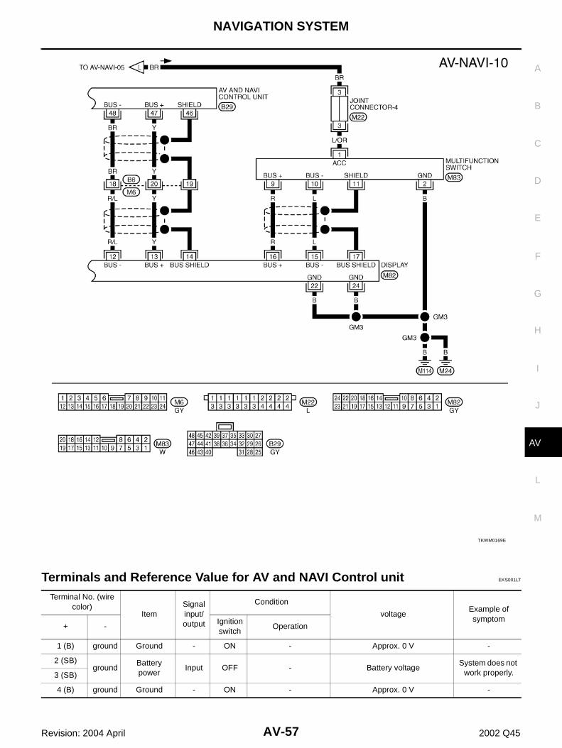
TKWM0169E
Terminal No. (wire color)
ItemSignal input/output
Condition
voltageExample of symptom
+ -Ignition switch
Operation
1 (B) ground Ground - ON - Approx. 0 V -
2 (SB)ground
Battery power
Input OFF - Battery voltageSystem does not
work properly.3 (SB)
4 (B) ground Ground - ON - Approx. 0 V -
AV-58
NAVIGATION SYSTEM
Revision: 2004 April 2002 Q45
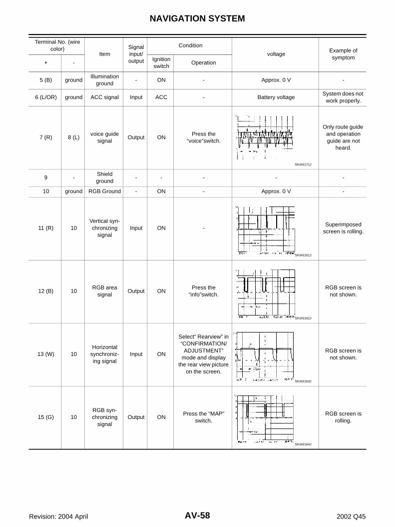
5 (B) groundIllumination
ground- ON - Approx. 0 V -
6 (L/OR) ground ACC signal Input ACC - Battery voltageSystem does not
work properly.
7 (R) 8 (L)voice guide
signalOutput ON
Press the “voice”switch.
Only route guide and operation guide are not
heard.
9 -Shield ground
- - - - -
10 ground RGB Ground - ON - Approx. 0 V -
11 (R) 10Vertical syn-chronizing
signalInput ON -
Superimposed screen is rolling.
12 (B) 10RGB area
signalOutput ON
Press the “info”switch.
RGB screen is not shown.
13 (W) 10Horizontal
synchroniz-ing signal
Input ON
Select“ Rearview” in “CONFIRMATION/
ADJUSTMENT” mode and display
the rear view picture on the screen.
RGB screen is not shown.
15 (G) 10RGB syn-chronizing
signalOutput ON
Press the “MAP” switch.
RGB screen is rolling.
Terminal No. (wire color)
ItemSignal input/output
Condition
voltageExample of symptom
+ -Ignition switch
Operation
SKIA0171J
SKIA0161J
SKIA0162J
SKIA0163J
SKIA0164J
NAVIGATION SYSTEM
AV-59
C
D
E
F
G
H
I
J
L
M
A
B
AV
Revision: 2004 April 2002 Q45
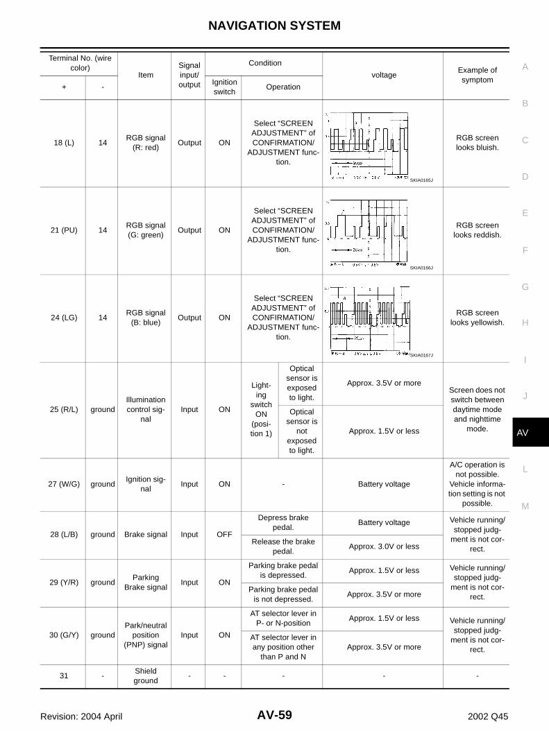
18 (L) 14RGB signal
(R: red)Output ON
Select “SCREEN ADJUSTMENT” of CONFIRMATION/
ADJUSTMENT func-tion.
RGB screen looks bluish.
21 (PU) 14RGB signal (G: green)
Output ON
Select “SCREEN ADJUSTMENT” of CONFIRMATION/
ADJUSTMENT func-tion.
RGB screen looks reddish.
24 (LG) 14RGB signal
(B: blue)Output ON
Select “SCREEN ADJUSTMENT” of CONFIRMATION/
ADJUSTMENT func-tion.
RGB screen looks yellowish.
25 (R/L) groundIllumination control sig-
nalInput ON
Light-ing
switch ON
(posi-tion 1)
Optical sensor is exposed to light.
Approx. 3.5V or moreScreen does not switch between daytime mode and nighttime
mode.
Optical sensor is
not exposed to light.
Approx. 1.5V or less
27 (W/G) groundIgnition sig-
nalInput ON - Battery voltage
A/C operation is not possible.
Vehicle informa-tion setting is not
possible.
28 (L/B) ground Brake signal Input OFF
Depress brake pedal.
Battery voltage Vehicle running/stopped judg-
ment is not cor-rect.
Release the brake pedal.
Approx. 3.0V or less
29 (Y/R) groundParking
Brake signalInput ON
Parking brake pedal is depressed.
Approx. 1.5V or less Vehicle running/stopped judg-
ment is not cor-rect.
Parking brake pedal is not depressed.
Approx. 3.5V or more
30 (G/Y) groundPark/neutral
position (PNP) signal
Input ON
AT selector lever in P- or N-position
Approx. 1.5V or less Vehicle running/stopped judg-
ment is not cor-rect.
AT selector lever in any position other
than P and NApprox. 3.5V or more
31 -Shield ground
- - - - -
Terminal No. (wire color)
ItemSignal input/output
Condition
voltageExample of symptom
+ -Ignition switch
Operation
SKIA0165J
SKIA0166J
SKIA0167J
AV-60
NAVIGATION SYSTEM
Revision: 2004 April 2002 Q45
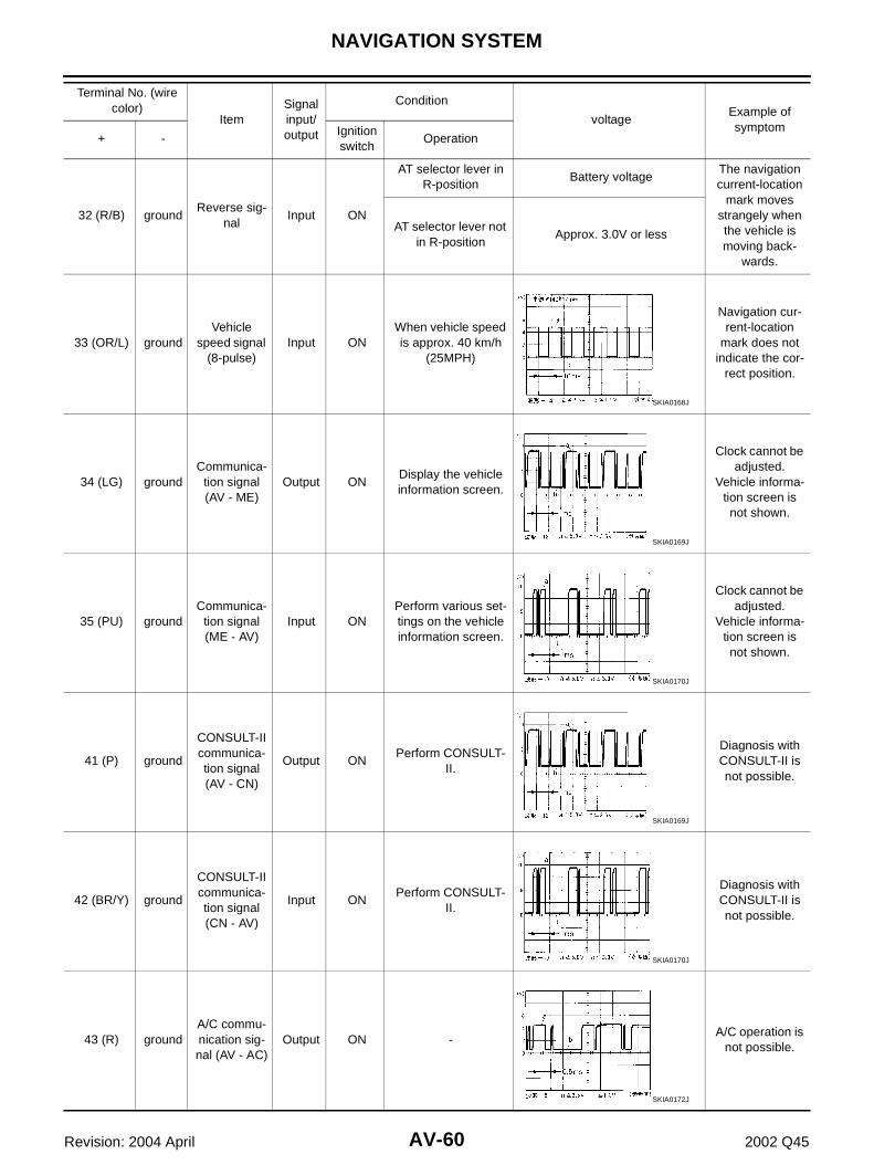
32 (R/B) groundReverse sig-
nalInput ON
AT selector lever in R-position
Battery voltageThe navigation current-location
mark moves strangely when the vehicle is moving back-
wards.
AT selector lever not in R-position
Approx. 3.0V or less
33 (OR/L) groundVehicle
speed signal (8-pulse)
Input ONWhen vehicle speed is approx. 40 km/h
(25MPH)
Navigation cur-rent-location
mark does not indicate the cor-
rect position.
34 (LG) groundCommunica-
tion signal (AV - ME)
Output ONDisplay the vehicle information screen.
Clock cannot be adjusted.
Vehicle informa-tion screen is not shown.
35 (PU) groundCommunica-
tion signal (ME - AV)
Input ONPerform various set-tings on the vehicle information screen.
Clock cannot be adjusted.
Vehicle informa-tion screen is not shown.
41 (P) ground
CONSULT-II communica-tion signal (AV - CN)
Output ONPerform CONSULT-
II.
Diagnosis with CONSULT-II is not possible.
42 (BR/Y) ground
CONSULT-II communica-tion signal (CN - AV)
Input ONPerform CONSULT-
II.
Diagnosis with CONSULT-II is not possible.
43 (R) groundA/C commu-nication sig-nal (AV - AC)
Output ON -A/C operation is
not possible.
Terminal No. (wire color)
ItemSignal input/output
Condition
voltageExample of symptom
+ -Ignition switch
Operation
SKIA0168J
SKIA0169J
SKIA0170J
SKIA0169J
SKIA0170J
SKIA0172J
NAVIGATION SYSTEM
AV-61
C
D
E
F
G
H
I
J
L
M
A
B
AV
Revision: 2004 April 2002 Q45
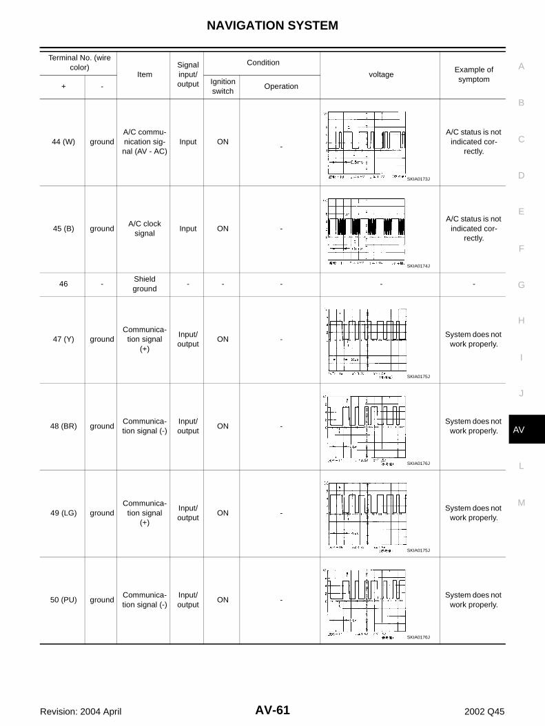
44 (W) groundA/C commu-nication sig-nal (AV - AC)
Input ON-
A/C status is not indicated cor-
rectly.
45 (B) groundA/C clock
signalInput ON -
A/C status is not indicated cor-
rectly.
46 -Shield ground
- - - - -
47 (Y) groundCommunica-
tion signal (+)
Input/output
ON -System does not
work properly.
48 (BR) groundCommunica-tion signal (-)
Input/output
ON -System does not
work properly.
49 (LG) groundCommunica-
tion signal (+)
Input/output
ON -System does not
work properly.
50 (PU) groundCommunica-tion signal (-)
Input/output
ON -System does not
work properly.
Terminal No. (wire color)
ItemSignal input/output
Condition
voltageExample of symptom
+ -Ignition switch
Operation
SKIA0173J
SKIA0174J
SKIA0175J
SKIA0176J
SKIA0175J
SKIA0176J
AV-62
NAVIGATION SYSTEM
Revision: 2004 April 2002 Q45
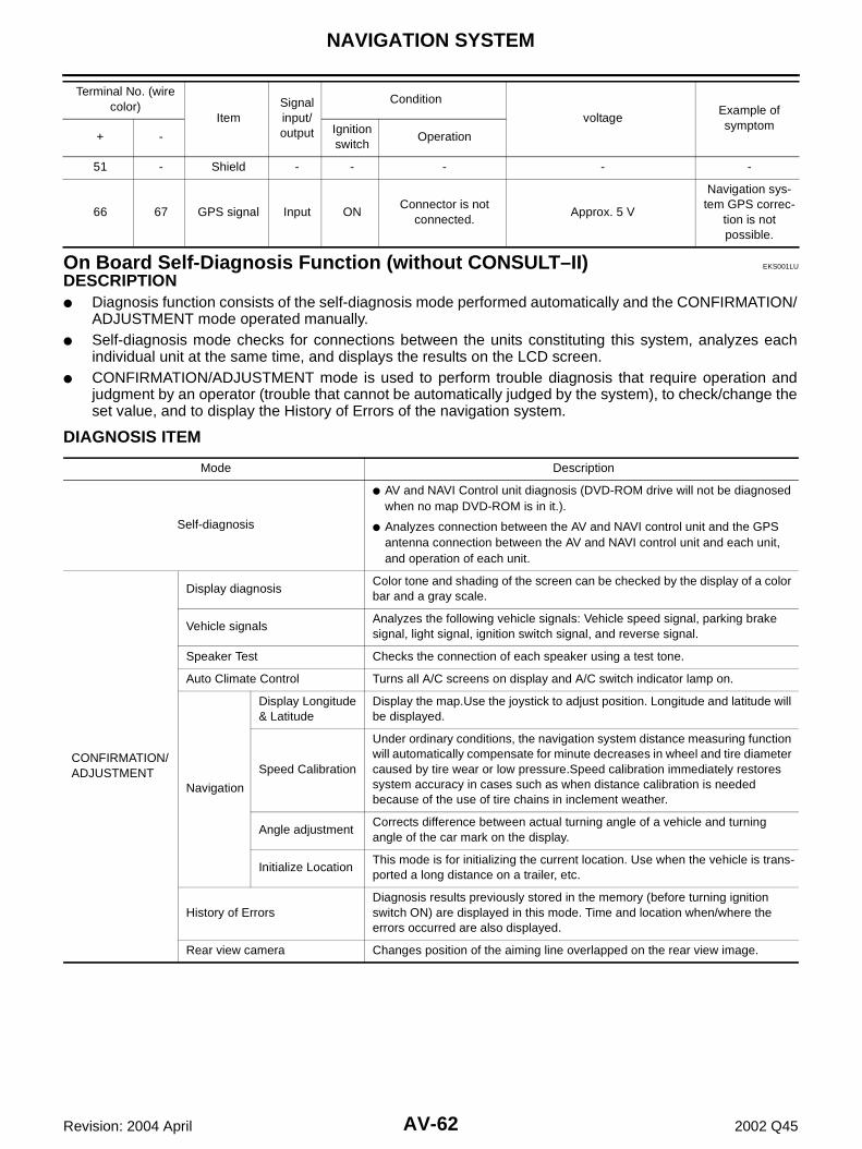
On Board Self-Diagnosis Function (without CONSULT–II) EKS001LU
DESCRIPTION ● Diagnosis function consists of the self-diagnosis mode performed automatically and the CONFIRMATION/
ADJUSTMENT mode operated manually.● Self-diagnosis mode checks for connections between the units constituting this system, analyzes each
individual unit at the same time, and displays the results on the LCD screen.● CONFIRMATION/ADJUSTMENT mode is used to perform trouble diagnosis that require operation and
judgment by an operator (trouble that cannot be automatically judged by the system), to check/change theset value, and to display the History of Errors of the navigation system.
DIAGNOSIS ITEM
51 - Shield - - - - -
66 67 GPS signal Input ONConnector is not
connected.Approx. 5 V
Navigation sys-tem GPS correc-
tion is not possible.
Terminal No. (wire color)
ItemSignal input/output
Condition
voltageExample of symptom
+ -Ignition switch
Operation
Mode Description
Self-diagnosis
● AV and NAVI Control unit diagnosis (DVD-ROM drive will not be diagnosed when no map DVD-ROM is in it.).
● Analyzes connection between the AV and NAVI control unit and the GPS antenna connection between the AV and NAVI control unit and each unit, and operation of each unit.
CONFIRMATION/ADJUSTMENT
Display diagnosisColor tone and shading of the screen can be checked by the display of a color bar and a gray scale.
Vehicle signalsAnalyzes the following vehicle signals: Vehicle speed signal, parking brake signal, light signal, ignition switch signal, and reverse signal.
Speaker Test Checks the connection of each speaker using a test tone.
Auto Climate Control Turns all A/C screens on display and A/C switch indicator lamp on.
Navigation
Display Longitude & Latitude
Display the map.Use the joystick to adjust position. Longitude and latitude will be displayed.
Speed Calibration
Under ordinary conditions, the navigation system distance measuring function will automatically compensate for minute decreases in wheel and tire diameter caused by tire wear or low pressure.Speed calibration immediately restores system accuracy in cases such as when distance calibration is needed because of the use of tire chains in inclement weather.
Angle adjustmentCorrects difference between actual turning angle of a vehicle and turning angle of the car mark on the display.
Initialize LocationThis mode is for initializing the current location. Use when the vehicle is trans-ported a long distance on a trailer, etc.
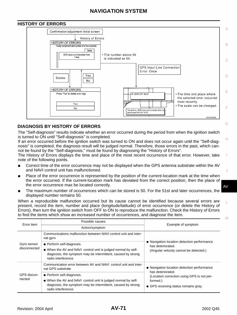
History of ErrorsDiagnosis results previously stored in the memory (before turning ignition switch ON) are displayed in this mode. Time and location when/where the errors occurred are also displayed.
Rear view camera Changes position of the aiming line overlapped on the rear view image.
NAVIGATION SYSTEM
AV-63
C
D
E
F
G
H
I
J
L
M
A
B
AV
Revision: 2004 April 2002 Q45
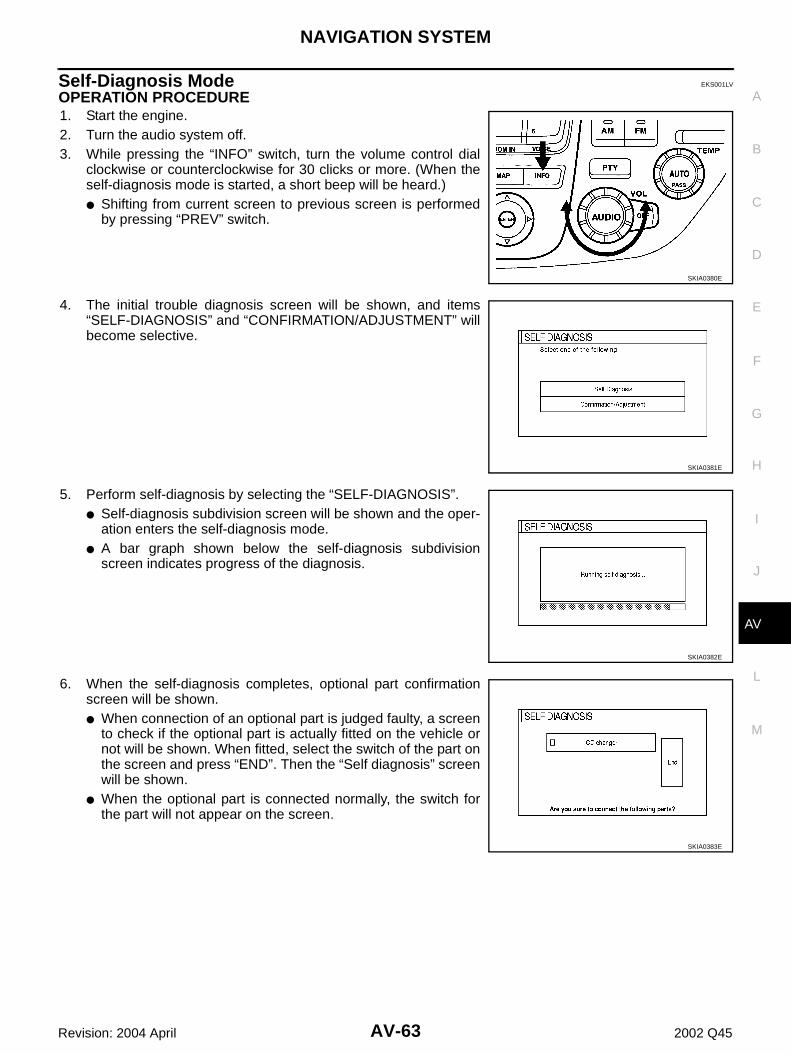
Self-Diagnosis Mode EKS001LV
OPERATION PROCEDURE 1. Start the engine.2. Turn the audio system off.3. While pressing the “INFO” switch, turn the volume control dial
clockwise or counterclockwise for 30 clicks or more. (When theself-diagnosis mode is started, a short beep will be heard.)● Shifting from current screen to previous screen is performed
by pressing “PREV” switch.
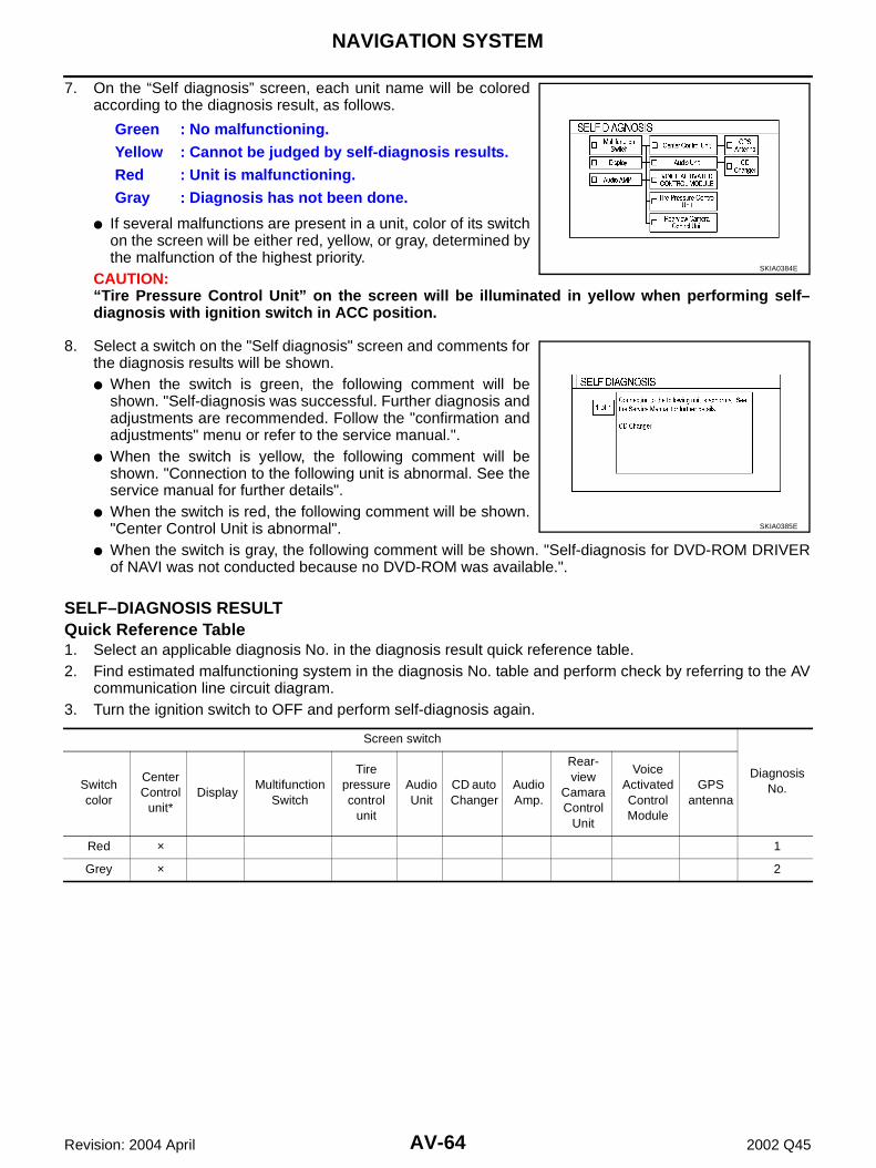
4. The initial trouble diagnosis screen will be shown, and items“SELF-DIAGNOSIS” and “CONFIRMATION/ADJUSTMENT” willbecome selective.
5. Perform self-diagnosis by selecting the “SELF-DIAGNOSIS”.● Self-diagnosis subdivision screen will be shown and the oper-
ation enters the self-diagnosis mode.● A bar graph shown below the self-diagnosis subdivision
screen indicates progress of the diagnosis.
6. When the self-diagnosis completes, optional part confirmationscreen will be shown.● When connection of an optional part is judged faulty, a screen
to check if the optional part is actually fitted on the vehicle ornot will be shown. When fitted, select the switch of the part onthe screen and press “END”. Then the “Self diagnosis” screenwill be shown.
● When the optional part is connected normally, the switch forthe part will not appear on the screen.
SKIA0380E
SKIA0381E
SKIA0382E
SKIA0383E
AV-64
NAVIGATION SYSTEM
Revision: 2004 April 2002 Q45
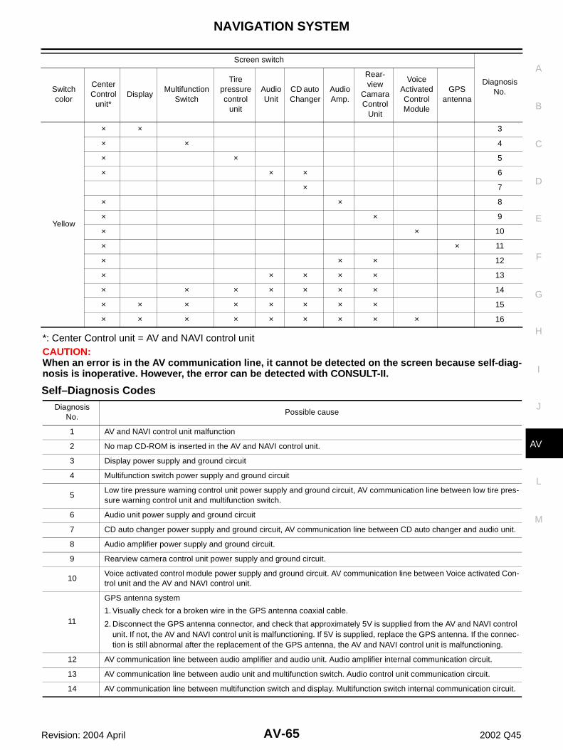
7. On the “Self diagnosis” screen, each unit name will be coloredaccording to the diagnosis result, as follows.
● If several malfunctions are present in a unit, color of its switchon the screen will be either red, yellow, or gray, determined bythe malfunction of the highest priority.
CAUTION:“Tire Pressure Control Unit” on the screen will be illuminated in yellow when performing self–diagnosis with ignition switch in ACC position.
8. Select a switch on the "Self diagnosis" screen and comments forthe diagnosis results will be shown.● When the switch is green, the following comment will be
shown. "Self-diagnosis was successful. Further diagnosis andadjustments are recommended. Follow the "confirmation andadjustments" menu or refer to the service manual.".
● When the switch is yellow, the following comment will beshown. "Connection to the following unit is abnormal. See theservice manual for further details".
● When the switch is red, the following comment will be shown."Center Control Unit is abnormal".
● When the switch is gray, the following comment will be shown. "Self-diagnosis for DVD-ROM DRIVERof NAVI was not conducted because no DVD-ROM was available.".
SELF–DIAGNOSIS RESULT Quick Reference Table1. Select an applicable diagnosis No. in the diagnosis result quick reference table.2. Find estimated malfunctioning system in the diagnosis No. table and perform check by referring to the AV
communication line circuit diagram.3. Turn the ignition switch to OFF and perform self-diagnosis again.
Green : No malfunctioning.Yellow : Cannot be judged by self-diagnosis results.Red : Unit is malfunctioning.Gray : Diagnosis has not been done.
SKIA0384E
SKIA0385E
Screen switch
Diagnosis No.Switch
color
Center Control
unit*Display
Multifunction Switch
Tire pressure control
unit
Audio Unit
CD auto Changer
Audio Amp.
Rear-view
Camara Control
Unit
Voice Activated Control Module
GPS antenna
Red × 1
Grey × 2
NAVIGATION SYSTEM
AV-65
C
D
E
F
G
H
I
J
L
M
A
B
AV
Revision: 2004 April 2002 Q45
*: Center Control unit = AV and NAVI control unitCAUTION:When an error is in the AV communication line, it cannot be detected on the screen because self-diag-nosis is inoperative. However, the error can be detected with CONSULT-II.
Self–Diagnosis Codes
Yellow
× × 3
× × 4
× × 5
× × × 6
× 7
× × 8
× × 9
× × 10
× × 11
× × × 12
× × × × × 13
× × × × × × × 14
× × × × × × × × 15
× × × × × × × × × 16
Screen switch
Diagnosis No.Switch
color
Center Control
unit*Display
Multifunction Switch
Tire pressure control
unit
Audio Unit
CD auto Changer
Audio Amp.
Rear-view
Camara Control
Unit
Voice Activated Control Module
GPS antenna
Diagnosis No.
Possible cause
1 AV and NAVI control unit malfunction
2 No map CD-ROM is inserted in the AV and NAVI control unit.
3 Display power supply and ground circuit
4 Multifunction switch power supply and ground circuit
5Low tire pressure warning control unit power supply and ground circuit, AV communication line between low tire pres-sure warning control unit and multifunction switch.
6 Audio unit power supply and ground circuit
7 CD auto changer power supply and ground circuit, AV communication line between CD auto changer and audio unit.
8 Audio amplifier power supply and ground circuit.
9 Rearview camera control unit power supply and ground circuit.
10Voice activated control module power supply and ground circuit. AV communication line between Voice activated Con-trol unit and the AV and NAVI control unit.
11
GPS antenna system
1. Visually check for a broken wire in the GPS antenna coaxial cable.
2. Disconnect the GPS antenna connector, and check that approximately 5V is supplied from the AV and NAVI control unit. If not, the AV and NAVI control unit is malfunctioning. If 5V is supplied, replace the GPS antenna. If the connec-tion is still abnormal after the replacement of the GPS antenna, the AV and NAVI control unit is malfunctioning.
12 AV communication line between audio amplifier and audio unit. Audio amplifier internal communication circuit.
13 AV communication line between audio unit and multifunction switch. Audio control unit communication circuit.
14 AV communication line between multifunction switch and display. Multifunction switch internal communication circuit.
AV-66
NAVIGATION SYSTEM
Revision: 2004 April 2002 Q45
15 AV communication line between display and the AV and NAVI control unit. Display internal communication circuit.
16
AV communication line circuit malfunction.
1. Disconnect the AV and NAVI cotrol unit SD B31 connector, perform self-diagnosis. If the Voice activated control module is displayed in yellow as a result of self-diagnosis, check for short the communication circuits between AV and NAVI control unit and Voice activated control module.
2. Check for any incidents in the communication circuits between the AV and NAVI control unit and display, Voice Acti-vated Control unit and display, display and multifunction switch, multifunction switch and low tire pressure warning control unit, multifunction switch and audio unit, audio unit and audio amplifier, audio amplifier and rear view camera control unit.
3. If the malfunction cannot be solved by the procedure above, the internal communication circuit of the AV and NAVI control unit is malfunctioning.
Diagnosis No.
Possible cause
NAVIGATION SYSTEM
AV-67
C
D
E
F
G
H
I
J
L
M
A
B
AV
Revision: 2004 April 2002 Q45
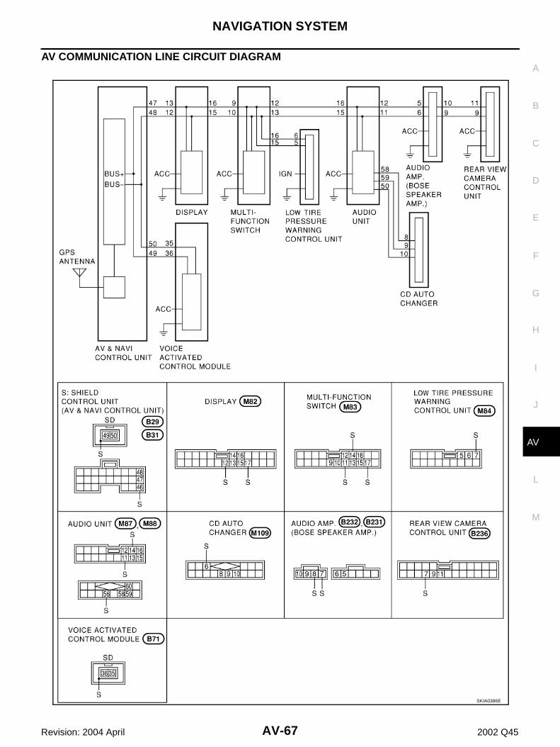
AV COMMUNICATION LINE CIRCUIT DIAGRAM
SKIA0386E
AV-68
NAVIGATION SYSTEM
Revision: 2004 April 2002 Q45
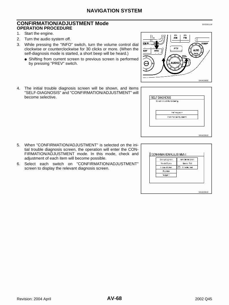
CONFIRMATION/ADJUSTMENT Mode EKS001LW
OPERATION PROCEDURE 1. Start the engine.2. Turn the audio system off.3. While pressing the "INFO" switch, turn the volume control dial
clockwise or counterclockwise for 30 clicks or more. (When theself-diagnosis mode is started, a short beep will be heard.)● Shifting from current screen to previous screen is performed
by pressing "PREV" switch.
4. The initial trouble diagnosis screen will be shown, and items"SELF-DIAGNOSIS" and "CONFIRMATION/ADJUSTMENT" willbecome selective.
5. When "CONFIRMATION/ADJUSTMENT" is selected on the ini-tial trouble diagnosis screen, the operation will enter the CON-FIRMATION/ADJUSTMENT mode. In this mode, check andadjustment of each item will become possible.
6. Select each switch on "CONFIRMATION/ADJUSTMENT"screen to display the relevant diagnosis screen.
SKIA0380E
SKIA0381E
SKIA0361E
NAVIGATION SYSTEM
AV-69
C
D
E
F
G
H
I
J
L
M
A
B
AV
Revision: 2004 April 2002 Q45
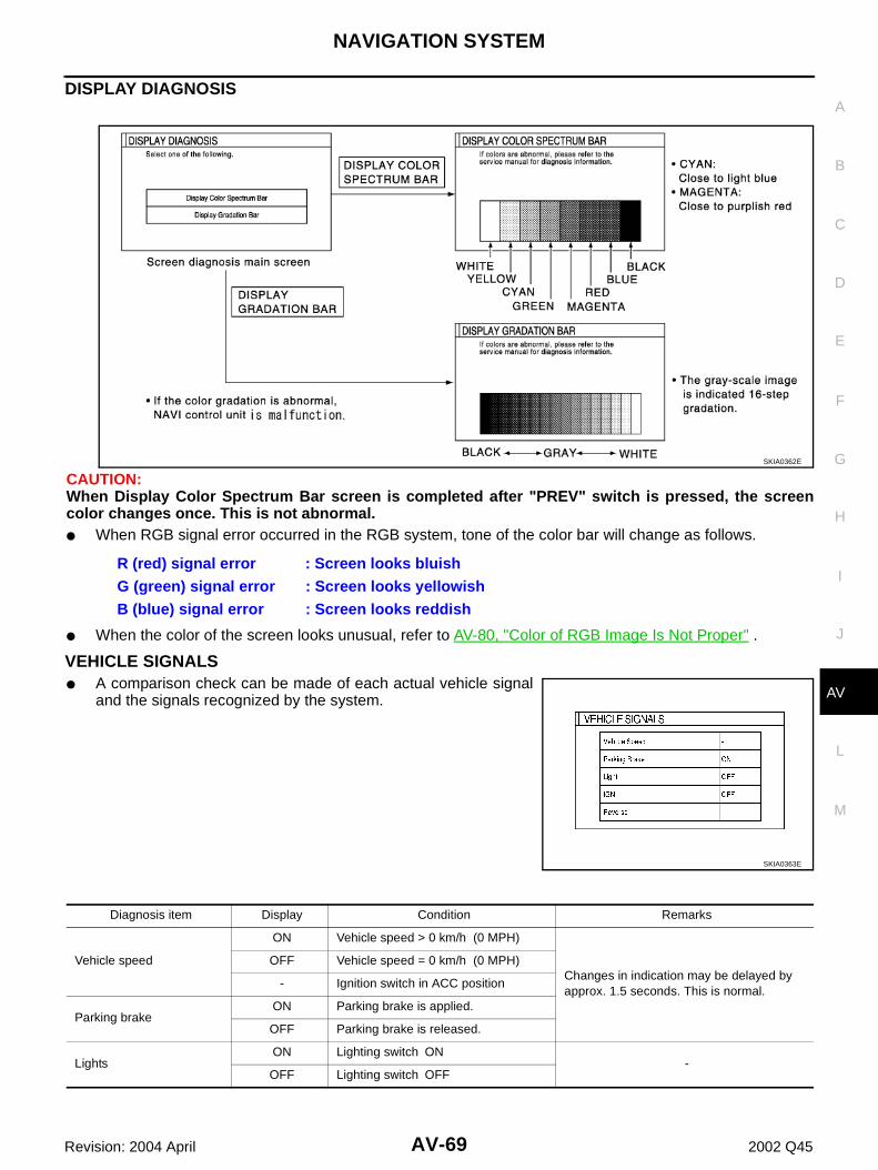
DISPLAY DIAGNOSIS
CAUTION:When Display Color Spectrum Bar screen is completed after "PREV" switch is pressed, the screencolor changes once. This is not abnormal.● When RGB signal error occurred in the RGB system, tone of the color bar will change as follows.
● When the color of the screen looks unusual, refer to AV-80, "Color of RGB Image Is Not Proper" .
VEHICLE SIGNALS ● A comparison check can be made of each actual vehicle signal
and the signals recognized by the system.
R (red) signal error : Screen looks bluishG (green) signal error : Screen looks yellowishB (blue) signal error : Screen looks reddish
SKIA0362E
SKIA0363E
Diagnosis item Display Condition Remarks
Vehicle speed
ON Vehicle speed > 0 km/h (0 MPH)
Changes in indication may be delayed by approx. 1.5 seconds. This is normal.
OFF Vehicle speed = 0 km/h (0 MPH)
- Ignition switch in ACC position
Parking brakeON Parking brake is applied.
OFF Parking brake is released.
LightsON Lighting switch ON
-OFF Lighting switch OFF
AV-70
NAVIGATION SYSTEM
Revision: 2004 April 2002 Q45
● If vehicle speed is NG, refer to AV-76, "Vehicle Speed Signal Check" .● If parking brake is NG, refer to AV-77, "Parking Brake Signal Check" .● If light is NG, refer to AV-77, "Illumination Control Signal Check" .● If IGN is NG, refer to AV-78, "Ignition Signal Check" .● If reverse is NG, refer to AV-78, "Reverse Signal Check"
SPEAKER TEST● Refer to AV-20, "Confirmation/Adjustment Mode" for the details.
AUTO CLIMATE CONTROL● Refer to "ATC Automatic Air Conditioner ATC-48, "Self-diagnosis Function" for the details.
NAVIGATION Angle Adjustment● Adjusts turning angle output detected by the gyroscope.
SPEED CALIBRATION● During normal driving, distance error caused by tire wear and
tire pressure change is automatically adjusted for by the auto-matic distance correction function. This function, on the otherhand, is for immediate adjustment, in cases such as driving withtire chain fitted on tires.
IGNON Ignition switch ON
-OFF Ignition switch ACC or OFF
Reverse
ON Selector lever in R-positionChanges in indication may be delayed by approx. 1.5 seconds. This is normal.
OFF Selector lever in other than R-position
- Ignition switch in ACC position
Diagnosis item Display Condition Remarks
SKIA0364E
SKIA0365E
NAVIGATION SYSTEM
AV-71
C
D
E
F
G
H
I
J
L
M
A
B
AV
Revision: 2004 April 2002 Q45
HISTORY OF ERRORS
DIAGNOSIS BY HISTORY OF ERRORSThe "Self-diagnosis" results indicate whether an error occurred during the period from when the ignition switchis turned to ON until "Self-diagnosis" is completed.If an error occurred before the ignition switch was turned to ON and does not occur again until the "Self-diag-nosis" is completed, the diagnosis result will be judged normal. Therefore, those errors in the past, which can-not be found by the "Self-diagnosis," must be found by diagnosing the "History of Errors".The History of Errors displays the time and place of the most recent occurrence of that error. However, takenote of the following points.● Correct time of the error occurrence may not be displayed when the GPS antenna substrate within the AV
and NAVI control unit has malfunctioned.● Place of the error occurrence is represented by the position of the current-location mark at the time when
the error occurred. If the current-location mark has deviated from the correct position, then the place ofthe error occurrence max be located correctly.
● The maximum number of occurrences which can be stored is 50. For the 51st and later occurrences, thedisplayed number remains 50.
When a reproducible malfunction occurred but its cause cannot be identified because several errors arepresent, record the item, number and place (longitude/latitude) of error occurrence (or delete the History ofErrors), then turn the ignition switch from OFF to ON to reproduce the malfunction. Check the History of Errorsto find the items which show an increased number of occurrences, and diagnose the item.
SKIA0366E
Error itemPossible causes
Example of symptomAction/symptom
Gyro sensor disconnected
Communications malfunction between NAVI control unit and inter-nal gyro
● Navigation location detection performance has deteriorated.(Angular velocity cannot be detected.)
● Perform self-diagnosis.
● When the AV and NAVI control unit is judged normal by self-diagnosis, the symptom may be intermittent, caused by strong radio interference.
GPS discon-nected
Communication error between AV and NAVI control unit and inter-nal GPS substrate ● Navigation location detection performance
has deteriorated.(Location correction using GPS is not per-formed.)
● GPS receiving status remains gray.
● Perform self-diagnosis.
● When the AV and NAVI control unit is judged normal by self-diagnosis, the symptom may be intermittent, caused by strong radio interference.
AV-72
NAVIGATION SYSTEM
Revision: 2004 April 2002 Q45
GPS trans-mission cable malfunction
Malfunctioning transmission wires to AV and NAVI control unit and internal GPS substrate
● During self-diagnosis, GPS diagnosis is not performed.
● Perform self-diagnosis.
● When the AV and NAVI control unit is judged normal by self-diagnosis, the symptom may be intermittent, caused by strong radio interference.
GPS input line connec-tion error
Malfunctioning receiving wires to AV and NAVI control unit and internal GPS substrate ● Navigation location detection performance
has deteriorated.(Location correction using GPS is not per-formed.)
● GPS receiving status remains gray.
● Perform self-diagnosis.
● When the AV and NAVI control unit is judged normal by self-diagnosis, the symptom may be intermittent, caused by strong radio interference.
GPS TCX0 overGPS TCX0 under
Oscillating frequency of the GPS substrate frequency synchroniz-ing oscillation circuit exceeded (or below) the specification ● Navigation location detection performance
has deteriorated.(Location correction using GPS is not per-formed.)
● GPS receiving status remains gray.
● Perform self-diagnosis.
● When the AV and NAVI control unit is judged normal by self-diagnosis, the symptom may be intermittent, caused by strong radio interference, or the control unit may have been subjected to excessively high or low temperatures.
GPS ROM malfunctionGPS RAM malfunction
Contents of ROM (or RAM) in GPS substrate are malfunctioning. ● Location detection accuracy of the navigation system will deteriorate, depending on the failed area in the memory, because GPS can-not make correct positioning.(Location correction using GPS is not per-formed.)
● Perform self-diagnosis.
● When the AV and NAVI control unit is judged normal by self-diagnosis, the symptom may be intermittent, caused by strong radio interference.
GPS RTC malfunction
Clock IC in GPS substrate is malfunctioning. ● Correct time may not be displayed.
● After the power is turned on, the system always takes some time until GPS positioning becomes possible. (The GPS receiver starts positioning without re-collecting the whole sat-ellite information when it judged the data stored in the receiver is correct.)
● Correct time of error occurrence may not be stored in the "History of Errors".
● Perform self-diagnosis.
● When the AV and NAVI control unit is judged normal by self-diagnosis, the symptom may be intermittent, caused by strong radio interference.
GPS antenna disconnected
Malfunctioning connection between GPS substrate in AV and NAVI control unit and GPS antenna. ● Navigation location detection performance
has deteriorated.(Location correction using GPS is not per-formed.)
● GPS receiving status remains gray.
● Perform self-diagnosis.
● When connection between AV and NAVI control unit and GPS antenna is judged normal by self-diagnosis, the symptom may be intermittent, caused by impact or vibration.
Low voltage of GPS
The power voltage supplied to the GPS circuit board has decreased. ● Navigation location detection performance
has deteriorated.(Location correction using GPS is not per-formed.)
● GPS receiving status remains gray.
● Perform self-diagnosis.
● When connection between AV and NAVI control unit and GPS antenna is judged normal by self-diagnosis, the symptom may be intermittent, caused by impact or vibration.
Error itemPossible causes
Example of symptomAction/symptom
NAVIGATION SYSTEM
AV-73
C
D
E
F
G
H
I
J
L
M
A
B
AV
Revision: 2004 April 2002 Q45
REAR VIEW CAMERA ● Refer to DI-146, "Confirmation/Adjustment Mode" for the details.
CONSULT-II Function EKS001LX
OPERATION PROCEDURE 1. Turn the ignition switch OFF.2. Connect CONSULT-II to vehicle side data link connector.3. Turn the ignition switch ON.4. Touch "START" and then "MULTI AV SYSTEM" on the CONSULT-II screen.
SELF-DIAG RESULTS ● Checks for connection between each unit and analyzes each individual unit, then displays the results on
DATA MONITOR● Displays status of the vehicle signal input to the AV and NAVI
control unit. (Refer to AV-68, "CONFIRMATION/ADJUSTMENTMode" for operation conditions for the connections to be indi-cated.)
● For each signal, a comparison of actual operating status and the status recognized by the system can bechecked.
VERSION Displays version of each unit connected to the AV and NAVI control unit.
PKIA0239E
DATA MONITOR item Display Condition Remarks
VHCL SPD SIG
ON Vehicle speed > km/h (0 MPH)
Changes in indication may be delayed by approx. 1.5 seconds. This is normal.
OFF Vehicle speed = km/h (0 MPH)
- Ignition switch in ACC position
BREAKON Parking brake is applied.
OFF Parking brake is released.
MTR ILL DIMON Lighting switch ON
-OFF Lighting switch OFF
IGN SWON Ignition switch ON
-OFF Ignition switch ACC or OFF
R POSI SIG
ON Selector lever in R-positionChanges in indication may be delayed by approx. 1.5 seconds. This is normal.
OFF Selector lever in other than R-position
- Ignition switch in ACC position
Version display Remarks
“PANEL SW” Multifunction switch
“MAP DISK” Map Disc
“HEAD UNIT” AV and NAVI control unit
“REAR VIEW CAMERA” -
“FRONT SEAT DISPLAY” Display
“AUDIO HEAD UNIT” -
“AIR COMP RECEIVER” Low Tire Pressure Warning Control Unit
PKIA0240E
NAVIGATION SYSTEM
AV-75
C
D
E
F
G
H
I
J
L
M
A
B
AV
Revision: 2004 April 2002 Q45
Power Supply and Ground Circuit Check EKS001LY
1. CHECK FUSE.
● Check that the following fuses of the AV and NAVI control unit are not blown.
OK or NGOK >> GO TO 2.NG >> If fuse is blown be sure to eliminate case of problem before installing new fuse, refer to PG-2,
"POWER SUPPLY ROUTING"
2. POWER SUPPLY CIRCUIT CHECK
1. Disconnect the AV and NAVI control unit connector. 2. Check voltage between the following harness connector termi-
nals and ground.
OK or NGOK >> GO TO 3.NG >> Check harness for open or short berween AV and NAVI control unit and fuse.
3. GROUND CIRCUIT CHECK
Check continuity between the following AV and NAVI control unit andground.
OK or NGOK >> Inspection end.NG >> Repair or replace harness.
"BOSE AMP" -
“VOICE UNIT” Voice Activated Control Module
Version display Remarks
TerminalsPower source Fuse No.
Connector Terminal (wire color)
B30 2(SB),3(SB) Battery power #52
B30 6(L/OR) ACC power #21
Terminals
Power source
Ignition switch
Reference voltage (V)
(+)
(-)Connector
Terminal (wire color)
B30 2(SB), 3(SB) GroundBattery power
OFF Approx. 12
B30 6(L/OR) GroundACC
powerACC Approx. 12 PKIA0200E
Terminals
Ignition switch Continuity(+)(-)
Connector Terminal (wire color)
B30 1(B),4(B),5(B) Ground OFF Yes
PKIA0201E
AV-76
NAVIGATION SYSTEM
Revision: 2004 April 2002 Q45
Vehicle Speed Signal Check EKS001LZ
1. HARNESS CHECK
1. Turn the ignition switch OFF.2. Disconnect AV and NAVI control unit connector and combination meter connector.3. Check continuity AV and NAVI control unit and combination meter.
4. Check continuity AV and NAVI control unit harness connectorterminal 33 and ground.
OK or NGOK >> GO TO 2.NG >> ● Check harness for open or short between AV and NAVI control unit and combination meter.
● Check connector housings for disconnected or loose terminals.
2. VEHICLE SPEED SIGNAL CHECK 1
1. Connect AV and NAVI control unit connector and combination meter connector.2. Turn the ignition switch ON.3. Check voltage between AV and NAVI control unit and ground.
OK or NGOK >> GO TO 3.NG >> Replace AV and NAVI control unit
3. VEHICLE SPEED SIGNAL CHECK 2
1. Connect combination meter connector.2. While driving vehicle at a constant speed, check voltage signal between AV and NAVI control unit and
ground.
OK or NGOK >> Replace AV and NAVI control unit.NG >> Check combination meter system, refer to DI-21,
"Inspection/Vehicle Speed Signal"
Terminals
ContinuityAV and NAVI control unit(+) combination meter(-)
ConnectorTerminal (wire
color)Connector
Terminal (wire color)
B29 33(OR/L) M41 17(OR/L) YES
Terminals
ContinuityAV and NAVI control unit(+)(-)
Connector Terminal (wire color)
B29 33(OR/L) Ground NO
PKIA0202E
Terminals
voltage (V)(+)(-)
Connector Terminal (wire color)
B30 33(OR/L) Ground Approx. 3.5 or more
PKIA0203E
Terminals
voltage (V)(+)(-)
Connector Terminal (wire color)
B30 33(OR/L) GroundAV-57, "Terminals and Refer-ence Value for AV and NAVI
Control unit"
PKIA0204E
NAVIGATION SYSTEM
AV-77
C
D
E
F
G
H
I
J
L
M
A
B
AV
Revision: 2004 April 2002 Q45
Parking Brake Signal Check EKS001M0
1. PARKING BRAKE CHECK
Depress Parking brake pedal and check if brake warning lamp comes on.OK or NGOK >> GO TO 2.NG >> Check parking brake system.refer toPB-3, "PARKING BRAKE SYSTEM" .
2. PARKING BRAKE SIGNAL CHECK
1. Turn the ignition switch ON.2. Check voltage between AV and NAVI control unit and ground
while depressing brake pedal.
OK or NGOK >> Replace AV and NAVI control unit.NG >> Check harness for open or short between AV and NAVI control unit and Parking brake switch.
Illumination Control Signal Check EKS001M1
1. ILLUMINATION CONTROL SIGNAL CHECK
1. Turn the ignition switch ON.2. Check voltage between AV and NAVI control unit and ground.
OK or NGOK >> Replace AV and NAVI control unit.NG >> Check harness for open or short between AV and NAVI
control unit and BCM.
TerminalsParking brake
(+)
(-)Connector
Terminal (wire color)
Release Depress
B29 29(Y/R) GroundApprox. 3.5V
or moreApprox. 1.5V or
less
PKIA0205E
TerminalsLight Switch
(+)
(-)Connector
Terminal (wire color)
ON OFF
B29 25(R/L) GroundApprox. 3.5V or
moreApprox. 1.5V or
less
PKIA0206E
AV-78
NAVIGATION SYSTEM
Revision: 2004 April 2002 Q45
Ignition Signal Check EKS001M2
1. IGNITION SIGNAL CHECK
1. Disconnect the AV and NAVI control unit connector.2. Turn the ignition switch ON.3. Check voltage between AV and NAVI control unit and ground.
OK or NGOK >> Replace AV and NAVI control unit.NG >> Check harness for open or short between AV and NAVI
control unit and fuse.
Reverse Signal Check EKS001M3
1. REVERSE LAMP CHECK
1. Turn the ignition switch ON.2. A/T Shift selector lever into R-position. Does "R" in the shift position indicator come on?YES or NOYES >> GO TO 2.NO >> Check park/neutral position relay system. Refer toAT-209, "PARK/NEUTRAL POSITION (PNP)
SWITCH"
2. REVERSE SIGNAL CHECK
With the selector lever in R-position, Check voltage between AV andNAVI control unit and ground.
OK or NGOK >> Replace AV and NAVI control unit.NG >> Check harness for open or short between AV and NAVI control unit and park/neutral position
relay.
TerminalsIgnition switch position
(+)
(-)Connector
Terminal (wire color)
ON OFF
B29 27(W/G) Ground Battery voltage 0V
PKIA0207E
TerminalsA/T selector lever position
(+)
(-)Connector
Terminal (wire color)
R-positionother than R-
position
B29 32(R/B) Ground Battery voltageApprox. 3.0V or
less
PKIA0208E
NAVIGATION SYSTEM
AV-79
C
D
E
F
G
H
I
J
L
M
A
B
AV
Revision: 2004 April 2002 Q45
RGB Screen Is Not Shown EKS001M4
1. HARNESS CHECK
1. Turn the ignition switch OFF.2. Disconnect AV and NAVI control unit connector and Display connector.3. Check continuity between AV and NAVI control unit and Display.
4. Check continuity between AV and NAVI control unit and ground.
OK or NGOK >> GO TO 2.NG >> ● Check harness for open or short between AV and NAVI control unit and Display.
● Check connector housings for disconnected or loose terminals.
2. HORIZONTAL SYNCHRONIZATION SIGNAL CHECK
1. Connect AV and NAVI control unit connector and Display connector.2. Turn the ignition switch ON.3. Check voltage between AV and NAVI control unit connector ter-
minals 13 and 10.
OK or NGOK >> GO TO 3.NG >> Replace Display.
Terminals
ContinuityAV and NAVI control unit (+) Display (-)
ConnectorTerminal
(wire color)Connector
Terminal (wire color)
B30 12 (B) M82 8 (LG) YES
B30 13 (W) M82 5 (L/Y) YES
Terminals
ContinuityAV and NAVI control unit(+)(-)
Connector Terminal (wire color)
B30 12(B),13(W) Ground NO
PKIA0209E
Terminals
voltage (v)AV and NAVI control unit
(+)AV and NAVI control
unit (-)
ConnectorTerminal
(wire color)Connector Terminal
B30 13 (W) B30 10AV-57, "Terminals and Ref-
erence Value for AV and NAVI Control unit"
PKIA0210E
AV-80
NAVIGATION SYSTEM
Revision: 2004 April 2002 Q45
3. RGB AREA SIGNAL CHECK
1. Press “INFO” switch.2. Check voltage between AV and NAVI control unit connector ter-
minals 12 and 10.
OK or NGOK >> Replace Display NG >> Replace AV and NAVI control unit
Color of RGB Image Is Not Proper EKS001M5
1. COLOR BAR DIAGNOSIS CHECK
Check color tone by "SCREEN ADJUSTMENT" of CONFIRMATION/ADJUSTMENT function.OK or NGOK >> Inspection end.NG >> GO TO 2.
Terminals
voltage (v)AV and NAVI control unit
(+)AV and NAVI control unit
(-)
ConnectorTerminal
(wire color)Connector Terminal
B30 12 (B) B30 10AV-57, "Terminals and Ref-
erence Value for AV and NAVI Control unit" PKIA0211E
NAVIGATION SYSTEM
AV-81
C
D
E
F
G
H
I
J
L
M
A
B
AV
Revision: 2004 April 2002 Q45
2. HARNESS CHECK
1. Turn the ignition switch OFF.2. Disconnect AV and NAVI control unit connector and Display connector.3. Check continuity between AV and NAVI control unit and Display.4. Check continuity between AV and NAVI control unit and ground.● When the screen looks bluish
● When the screen looks reddish
● When the screen looks yellowish
OK or NGOK >> GO TO 3.NG >> ● Check harness for open or short between AV and NAVI control unit and Display.
● Check connector housings for disconnected or loose terminals.
Terminals
ContinuityAV and NAVI control unit (+) Display (-)
ConnectorTerminal
(wire color)Connector
Terminal (wire color)
B30 18 (L) M82 1 (L) YES
B30 14 M82 4 YES
Terminals
ContinuityAV and NAVI control unit(+)(-)
Connector Terminal (wire color)
B30 14,18 (L) Ground NO
PKIA0212E
Terminals
ContinuityAV and NAVI control unit (+) Display (-)
ConnectorTerminal
(wire color)Connector
Terminal (wire color)
B30 21 (PU) M82 2 (Y) YES
B30 14 M82 4 YES
Terminals
ContinuityAV and NAVI control unit(+)(-)
Connector Terminal (wire color)
B30 14,21 (PU) Ground NO
PKIA0213E
Terminals
ContinuityAV and NAVI control unit (+) Display (-)
ConnectorTerminal
(wire color)Connector
Terminal (wire color)
B30 24 (LG) M82 3 (G) YES
B30 14 M82 4 YES
Terminals
ContinuityAV and NAVI control unit(+)(-)
Connector Terminal (wire color)
B30 14,24 (LG) Ground NO
PKIA0214E
AV-82
NAVIGATION SYSTEM
Revision: 2004 April 2002 Q45
3. RGB SIGNAL CHECK
1. Connect AV and NAVI control unit connector and Display connector.2. Turn the ignition switch ON.3. Display “Color bar" by “CONFIRMATION/ADJUSTMENT” mode.4. Check voltage between AV and NAVI control unit terminals 18,
21, 24 and 14.● When the screen looks bluish
● When the screen looks reddish
● When the screen looks yellowish
OK or NGOK >> Replace DisplayNG >> Replace AV and NAVI control unit
Terminals
voltage (v)AV and NAVI control
unit (+)AV and NAVI control unit
(-)
Connec-tor
Terminal (wire color)
Connector Terminal
B30 18 (L) B30 14AV-57, "Terminals and Ref-
erence Value for AV and NAVI Control unit"
PKIA0215E
Terminals
voltage (v)AV and NAVI control unit (+) AV and NAVI control unit (-)
B30 24 (LG) B30 14AV-57, "Terminals and Reference Value for
AV and NAVI Control unit"
NAVIGATION SYSTEM
AV-83
C
D
E
F
G
H
I
J
L
M
A
B
AV
Revision: 2004 April 2002 Q45
RGB Screen Is Rolling EKS001M6
1. HARNESS CHECK
1. Turn the ignition switch OFF.2. Disconnect AV and NAVI control unit connector and Display connector.3. Check continuity between AV and NAVI control unit and Display.
4. Check continuity between AV and NAVI control unit and ground.
OK or NGOK >> GO TO 2.NG >> ● Check harness for open or short between AV and NAVI control unit and Display for open or
short circuit.● Check connector housings for disconnected or loose terminals.
2. RGB SYNCHRONIZING SIGNAL CHECK
1. Connect AV and NAVI control unit connector and Display connector.2. Turn the ignition switch ON.3. Check voltage between AV and NAVI control unit terminals 15 and 14.
OK or NGOK >> Replace Display.NG >> Replace AV and NAVI control unit.
Guide Sound Is Not Heard EKS001M7
1. CHECK VOICE GUIDE SETTING.
● While driving in the dark pink route, voice guide does not operate.(note)● Is volume setting not switched ON?NOTE:Voice guide is only available at intersections that satisfy certain conditions (indicated by ● on the map). There-fore, guidance may not be given even when the route on the map changes direction.YES or NOYES >> GO TO 2.NO >> Switch the setting ON and turn the volume up.
Terminals
ContinuityAV and NAVI control unit (+) Display (-)
ConnectorTerminal
(wire color)Connector
Terminal (wire color)
B30 15 (G) M82 7 (L/R) YES
B30 10 M82 4 YES
Terminals
ContinuityAV and NAVI control unit (+)(-)
Connector Terminal (wire color)
B30 10,15 (G) Ground NO
PKIA0216E
Terminals
Reference signalAV and NAVI control unit
(+)AV and NAVI control unit
(-)
ConnectorTerminal
(wire color)Connector Terminal
B30 15 (G) B30 10AV-57, "Terminals and Ref-
erence Value for AV and NAVI Control unit"
PKIA0217E
AV-84
NAVIGATION SYSTEM
Revision: 2004 April 2002 Q45
2. HARNESS CHECK
1. Turn the ignition switch OFF.2. Disconnect AV and NAVI control unit connector and Bose speaker amp. connector.3. Check continuity between AV and NAVI control unit and Bose speaker amp.
4. Check continuity between AV and NAVI control unit and ground.
Ok or NGOK >> GO TO 3.NG >> ● Check harness for open or short between AV and NAVI control unit and Bose speaker amp.
● Check connector housings for disconnected or loose terminals.
3. VOICE GUIDE CHECK
1. Connect AV and NAVI control unit connector and Bose speaker amp. connector.2. Turn the ignition switch ON.3. Check voltage signal between AV and NAVI control unit termi-
nals 8 and 7.
Ok or NGOK >> Replace Bose speaker amp.NG >> Replace AV and NAVI control unit
Terminals
ContinuityAV and NAVI control unit (+) Bose speaker amp. (-)
ConnectorTerminal
(wire color)Connector
Terminal (wire color)
B30 7 (R) B232 1 (R) YES
B30 8 (L) B232 2 (L) YES
Terminals
ContinuityAV and NAVI control unit(+)(-)
Connector Terminal (wire color)
B30 7 (R),8 (L) Ground NO
PKIA0218E
Terminals
voltage (v)AV and NAVI control unit
(+)AV and NAVI control unit
(-)
ConnectorTerminal
(wire color)Connector Terminal
B30 7 (R) B30 8(L)AV-57, "Terminals and Ref-
erence Value for AV and NAVI Control unit" PKIA0219E
NAVIGATION SYSTEM
AV-85
C
D
E
F
G
H
I
J
L
M
A
B
AV
Revision: 2004 April 2002 Q45
No A/C Display is Shown EKS001M8
1. HARNESS CHECK
1. Turn the ignition switch OFF.2. Disconnect A/C AUTO AMP. connector and AV and NAVI control unit connector.3. Check continuity between A/C AUTO AMP. and AV and NAVI control unit.
4. Check continuity between AV and NAVI control unit and ground.
OK or NGOK >> GO TO 2.NG >> ● Check harness between A/C AUTO AMP. and AV and NAVI control unit.
● Check connector housings for disconnected or loose terminals.
2. A/C–AV, AC–CLK COMMUNICATION SIGNAL CHECK
1. Connect A/C AUTO AMP. connector.2. Turn the ignition switch ON.3. Check voltage between AV and NAVI control unit and ground.
OK or NGOK >> GO TO 3.NG >> Replace A/C AUTO AMP.
Terminals
ContinuityAV and NAVI control unit (+) A/C AUTO AMP. (-)
ConnectorTerminal
(wire color)Connector
Terminal (wire color)
B29 44 (W) M119 9 (W) YES
B29 45 (B) M119 20 (B) YES
Terminals
ContinuityAV and NAVI control unit(+)(-)
Connector Terminal (wire color)
B30 44 (W),45 (B) Ground NO
PKIA0220E
Terminals
Voltage (V)(+)(-)
Connector Terminal (wire color)
B29 44(W),45 (B) ground Approx. 3.5 or more
PKIA0221E
AV-86
NAVIGATION SYSTEM
Revision: 2004 April 2002 Q45
3. A/C - AV, AC - CLK COMMUNICATION SIGNAL CHECK
1. Connect AV and NAVI control unit connector.2. Turn the ignition switch ON.3. Check voltage between AV and NAVI control unit terminals 44,
45 and ground.
OK or NGOK >> Replace A/C auto amplifierNG >> Replace AV and NAVI control unit
A/C Operation Is Not Possible. EKS001M9
1. HARNESS CHECK
1. Turn the ignition switch OFF.2. Disconnect A/C AUTO AMP. connector and AV and NAVI control unit connector.3. Check continuity between A/C AUTO AMP. and AV and NAVI control unit.
4. Check continuity between AV and NAVI control unit and ground.
OK or NGOK >> GO TO 2.NG >> ● Check harness for open or short between A/C AUTO AMP. and AV and NAVI control unit for
open circuit.● Check connector housings for disconnected or loose terminals.
Terminals
Reference signal(+)
(-)Connector
Terminal (wire color)
B29 44(W),45 (B) groundAV-57, "Terminals and Refer-
ence Value for AV and NAVI Con-trol unit"
PKIA0222E
Terminals
ContinuityAV and NAVI control unit (+) A/C AUTO AMP. (-)
ConnectorTerminal
(wire color)Connector
Terminal (wire color)
B29 43 (R) M119 10 (R) YES
B29 45 (B) M119 20 (B) YES
Terminals
ContinuityAV and NAVI control unit(+)(-)
Connector Terminal (wire color)
B30 43 (R),45 (B) Ground NO
PKIA0223E
NAVIGATION SYSTEM
AV-87
C
D
E
F
G
H
I
J
L
M
A
B
AV
Revision: 2004 April 2002 Q45
2. AV - A/C, AC - CLK COMMUNICATION SIGNAL CHECK
1. Connect A/C AUTO AMP. connector.2. Turn the ignition switch ON.3. Check voltage between AV and NAVI control unit terminal 43
and ground.
OK or NGOK >> GO TO 3.NG >> Replace A/C auto amplifier
3. AV–A/C, AC–CLK COMMUNICATION SIGNAL CHECK
1. Connect AV and NAVI control unit connector.2. Turn the ignition switch ON.3. Check voltage between AV and NAVI control unit terminals 43,
45 and ground.
OK or NGOK >> Replace A/C auto amplifierNG >> Replace AV and NAVI control unit
Terminals
Reference voltage (V)(+)(-)
Connector Terminal (wire color)
B29 43 (R) ground Approx. 3.5 or more
PKIA0224E
Terminals
Reference signal(+)
(-)Connector
Terminal (wire color)
B29 43 (R),45 (B) groundAV-57, "Terminals and Reference
Value for AV and NAVI Control unit"
PKIA0225E
AV-88
NAVIGATION SYSTEM
Revision: 2004 April 2002 Q45
No Fuel Information Is Displayed/No Warning Message Is Displayed. EKS001MA
1. HARNESS CHECK
1. Turn the ignition switch OFF.2. Disconnect connectors of combination meter, BCM, and AV and NAVI control unit.3. Check continuity between AV and NAVI control unit and combination meter.
4. Check continuity between AV and NAVI control unit and ground.
OK or NGOK >> GO TO 2.NG >> ● Check harness for open or short between AV and NAVI control unit and combination meter for
open or short circuit.● Check connector housings for disconnected or loose terminals.
2. COMMUNICATION SIGNAL (AV–ME) CHECK
1. Connect connectors of combination meter, BCM, and AV and NAVI control unit.2. Turn the ignition switch ON.3. Check voltage between AV and NAVI control unit terminal 34 and ground.
OK or NGOK >> GO TO 3.NG >> Replace AV and NAVI control unit
Terminals
ContinuityAV and NAVI control unit (+) combination meter (-)
ConnectorTerminal
(wire color)Connector
Terminal (wire color)
B29 34 (LG) M41 7 (LG) YES
B29 35 (PU) M41 6 (PU) YES
Terminals
ContinuityAV and NAVI control unit(+)(-)
Connector Terminal (wire color)
B29 34 (LG),35 (PU) Ground NO
PKIA0226E
Terminals
Voltage (V)(+)(-)
Connector Terminal (wire color)
B29 34 (LG) groundAV-57, "Terminals and Refer-ence Value for AV and NAVI
Control unit"
PKIA0227E
NAVIGATION SYSTEM
AV-89
C
D
E
F
G
H
I
J
L
M
A
B
AV
Revision: 2004 April 2002 Q45
3. COMMUNICATION SIGNAL (ME–AV) CHECK
1. Turn ignition switch to ON and display “VEHICLE ELECTRONIC SYSTEMS”screen.2. Check voltage between AV and NAVI control unit terminal 35
and ground.
OK or NGOK >> Replace AV and NAVI control unit.NG >> Replace combination meter,.
Vehicle Condition Setting Is Not Possible. EKS001MB
1. HARNESS CHECK
1. Turn the ignition switch OFF.2. Disconnect connectors of combination meter, BCM, and AV and NAVI control unit.3. Check continuity AV and NAVI control unit and BCM.
4. Check continuity between AV and NAVI control unit and ground.
OK or NGOK >> GO TO 2.NG >> ● Check harness between AV and NAVI control unit and BCM for open or short circuit.
● Check connector housings for disconnected or loose terminals.
Terminals
Voltage (V)(+)(-)
Connector Terminal (wire color)
B29 35 (PU) groundAV-57, "Terminals and Refer-ence Value for AV and NAVI
Control unit"
PKIA0228E
Terminals
ContinuityAV and NAVI control unit (+) BCM (-)
ConnectorTerminal
(wire color)Connector
Terminal (wire color)
B29 34 (LG) M4 31 (LG) YES
B29 35 (PU) M4 30 (PU) YES
Terminals
ContinuityAV and NAVI control unit(+)(-)
Connector Terminal (wire color)
B29 34 (LG),35 (PU) Ground NO
PKIA0229E
AV-90
NAVIGATION SYSTEM
Revision: 2004 April 2002 Q45
2. COMMUNICATION SIGNAL (AV–ME) CHECK
1. Connect connectors of combination meter, BCM, and control unit.2. Turn the ignition switch ON.3. Check voltage signal between AV and NAVI control unit terminal 34 and ground.
OK or NGOK >> GO TO 3.NG >> Replace AV and NAVI control unit
3. COMMUNICATION SIGNAL (ME–AV) CHECK
1. Turn ignition switch to ON and display "VEHICLE ELECTRONIC SYSTEMS"screen.2. Check voltage signal between AV and NAVI control unit terminal 35 and ground.
OK or NGOK >> Replace AV and NAVI control unit.NG >> Replace BCM .
Previous Conditions Are Not Stored. EKS001MC
1. BATTERY POWER CHECK
● Check AV and NAVI control unit battery power.Refer toAV-75, "Power Supply and Ground Circuit Check" .
OK or NGOK >> Replace AV and NAVI control unitNG >> Check AV and NAVI control unit battery power system harness
The Position of The Current-Location Mark Is Not Correct. EKS001MD
1. SELF-DIAGNOSIS
● "Self-diagnosis mode" of the self-diagnosis functionAV-63, "Self-Diagnosis Mode" .OK or NGOK >> GO TO 2.NG >> Check the applicable parts.
2. HISTORY OF ERRORS DIAGNOSIS
● Was any error stored in AV-71, "HISTORY OF ERRORS" of the CONFIRMATION/ADJUSTMENT mode?YES or NOYES >> AV-71, "DIAGNOSIS BY HISTORY OF ERRORS".NO >> .AV-91, "Driving Test"
Terminals
Reference signal(+)(-)
Connector Terminal (wire color)
B29 34 (LG) groundAV-57, "Terminals and Refer-ence Value for AV and NAVI
Control unit"
PKIA0227E
Terminals
Reference signal(+)(-)
Connector Terminal (wire color)
B29 35 (PU) groundAV-57, "Terminals and Refer-ence Value for AV and NAVI
Control unit"
PKIA0228E
NAVIGATION SYSTEM
AV-91
C
D
E
F
G
H
I
J
L
M
A
B
AV
Revision: 2004 April 2002 Q45
Radio Wave From The GPS Satellite Is Not Received. EKS001ME
1. ENVIRONMENT CHECK
● Check if any metal object that intercepts radio waves or an object that emits radio waves (such as a porta-ble phone) is located near the GPS antenna. Check if the vehicle is shielded by a building.
OK or NGOK >> ● System is not faulty.
The GPS antenna may not be able to receive radio waves from the GPS satellite if it is shieldedby metal object or an object emitting radio waves is placed near it.
NG >> GO TO 2.
2. SELF-DIAGNOSIS
● Refer to AV-63, "Self-Diagnosis Mode" .OK or NGOK >> Replace GPS antennaNG >> Check the applicable parts.
Driving Test EKS001MF
1. DRIVING TEST 1
1. Scroll the map screen to display the area to make correction. Press "ENTER" and select "CURRENTLOCATION CORRECTION".
2. Correct direction of the vehicle mark.3. Perform the distance correction of the CONFIRMATION/ADJUSTMENT mode.
Note: Normally, adjustment is not necessary because this system has automatic distance correction func-tion. However, when a tire chain is fitted, adjustment in accordance with the tire diameter ratio must bemade.
4. Are symptoms applicable to the AV-92, "Example of Symptoms Judged Not Abnormal" present after driv-ing the vehicle?
YES or NOYES >> Limit of the location detection capacity of the navigation systemNO >> GO TO 2.
2. DRIVING TEST 2
● Did any problem occur when the proper test in the following test patterns is performed?● Test pattern
Driving test finds the difference between the symptoms monitored with and without each sensor.– Test pattern 1: Test method with no GPS location correction
Disconnect the GPS antenna connector (GT5) connected to the AV and NAVI control unit. Accuratelyadjust the current position and the direction, then drive the vehicle.
– Test pattern 2: Test method with no map-matchingAccurately adjust the current position and the direction. Eject the map DVD-ROM from the AV and NAVIcontrol unit with the ignition switch turned to OFF, then drive the vehicle. After driving, insert the map
AV-92
NAVIGATION SYSTEM
Revision: 2004 April 2002 Q45
DVD-ROM back in the unit, display the track of the vehicle on the map screen and compare it with theactual road configuration.
● Sample tests– <To determine if the current-location mark skips at the same position, if so, whether it is caused by map-
matching or by GPS>Perform test pattern 1.
– <To determine if the pattern of streets displayed is correct or not>Perform test pattern 1&2.Compare the track of the vehicle on the map screen and the actual road configuration. For fairly accuratetracking, plotting shall be made every several hundred meters.
– <When the distance is adjusted accurately>Perform test pattern 1&2.Drive on a road of which distance is accurately known (by utilizing distance posts on a highway). Calculatethe rate of change (increased/decreased) of the distance by comparing with the actual distance.Correction = A/BA: Distance shown on the screenB: Actual distance
YES or NOYES >> ● If adjustment is insufficient, perform adjustment again.
● If any error is found in the map, please let us know.● Replace AV and NAVI control unit
NO >> Limit of the location detection capacity of the navigation system
Example of Symptoms Judged Not Abnormal EKS001MG
BASIC OPERATION
VEHICLE MARK
Symptom Cause Remedy
No image is shown. Display brightness adjustment is set fully to DARK side.
Adjust the display brightness.
No guide sound is heard.Audio guide volume is too low or too high.
Volume control is set to OFF, MIN or MAX. Adjust the audio guide volume.
Audio guidance is not available while the vehicle is driving on a dark pink route.
System is not malfunction.
Screen is too dark.Motion of the image is too slow.
Temperature inside the vehicle is low. Wait until the temperature inside the vehicle reaches the proper temperature.
Small black or bright spots appear on the screen.
Symptom peculiar to a liquid crystal display. System is not malfunction.
Symptom Cause Remedy
Map screen and bird view ™Name of the place vary with the screen.
Some thinning of the character data is done to prevent the display becoming to complex. In some cases and in some locations, the display contents may differ.The same place name, street name, etc. may not be displayed every time on account of the data processing.
System is not malfunction.
Vehicle mark is not positioned cor-rectly.
Vehicle is transferred by ferry or by towing after its ignition switch is turned to OFF.
Drive the vehicle for a while in the GPS sat-ellite signal receiving condition.
Screen will not switch to nighttime mode after the lighting switch is turned ON.
The daytime screen is selected by the "SWITCH SCREENS" when the last time the screen dim-ming setting is done.Switching between daytime/nighttime screen may be inhibited by the automatic illumination adjust-ment function.
Perform screen dimming and select the nighttime screen by "SWITCH SCREENS".
Map screen will not scroll in accor-dance with the vehicle travel.
Current location is not displayed. Press "MAP" switch to display the current location.
Vehicle mark will not be shown. Current location is not displayed. Press "MAP" switch to display the current location.
NAVIGATION SYSTEM
AV-93
C
D
E
F
G
H
I
J
L
M
A
B
AV
Revision: 2004 April 2002 Q45
DESTINATION, PASSING POINTS, AND MENU ITEMS CANNOT BE SELECTED/SET.
Accuracy indicator (GPS satellite mark) on the map screen stays gray.
GPS satellite signal is intercepted because the vehicle is in or behind a building.
Move the vehicle out to an open space.
GPS satellite signal cannot be received because an obstacle is placed on top of the display.
Do not place anything in the center on top of the display.
GPS satellites are located badly. Wait until the location becomes better.
Vehicle location accuracy is low. Accuracy indicator (GPS satellite mark) on the map screen stays gray.
Current location is not determined.
Vehicle speed setting by the vehicle speed pulse has been deviated (advanced or retarded) from the actual vehicle speed because tire chain is fit-ted or the system has been used on another vehi-cle.
Drive the vehicle for a while {for approx. 30 minutes at approx. 30 km/h(19MPH)} and the deviation will be automatically adjusted. If advancement or retard still occur, perform the distance adjustment by CONFIRMA-TION/ADJUSTMENT mode of diagnosis function.
Map data has error or omission. (Vehicle mark is always deviated to the same position.)
As a rule, an updated map DVD-ROM will be released once a year.
Symptom Cause Remedy
Symptom Cause Remedy
Destination cannot be set. Destination to be set is on an expressway. Set the destination on an ordinary road.
Passing point is not searched when re-searching the route.
The vehicle has already passed the passing point, or the system judged so.
To include the passing points that have been passed into the route again, set the route again.
Route information will not be dis-played.
Route searching has not been done. Set the destination and perform route searching.
Vehicle mark is not on the recommended route. Drive on the recommended route.
Route guide is turned OFF. Turn the route guide ON.
Route information is not available on the dark pink route.
System is not malfunction.
After the route searching, no guide sign will appear as the vehicle goes near the entrance/exit to the toll road.
Vehicle mark is not on the recommended route. (On the display, only guide signs related to the recommended route will be shown.)
Drive on the recommended route.
Automatic route searching is not possible.
Vehicle is driving on a highway (gray route), or no recommended route is available.
Drive on a road to be searched. Or re-search the route manually. In this case, how-ever, the whole route will be searched.
Performed automatic detour search (or detour search). How-ever, the result is the same as that of the previous search.
Performed search with every conditions consid-ered. However, the result is the same as that of the previous search.
System is not malfunction.
Passing points cannot be set. More than five passing points were set. Passing points can be set up to five. To stop at more than five points, perform sharing in several steps.
When setting the route, the start-ing point cannot be selected.
The current vehicle location is always set as the starting point of a route.
System is not malfunction.
Some menu items cannot be selected.
The vehicle is being driven. Stop the vehicle at a safe place and then operate the system.
AV-94
NAVIGATION SYSTEM
Revision: 2004 April 2002 Q45
VOICE GUIDE
ROUTE SEARCHING
NOTE:Except for the ordinance-designated cities and the prefectural capitals (Applicable areas may be changed in the updated map disc.)
Symptom Cause Remedy
Voice guide will not operate. Note: Voice guide is only available at intersections that satisfy certain conditions (indicated by ● on the map). Therefore, guidance may not be given even when the route on the map changes direc-tion.
System is not malfunction.
The vehicle is not on the recommended route. Return to the recommended route or re-search the route.
Voice guide is turned OFF. Turn the voice guide ON.
Route guide is turned OFF. Turn the route guide ON.
Voice guide does not match the actual road pattern.
Voice guide may vary with the direction to which the vehicle is turn and the connection of the road to other roads.
Drive in conformity to the actual traffic rules.
Symptom Cause Remedy
No route is shown. No road to be searched is found around the des-tination.
Find wider road (orange road or wider) nearby and reset the destination and passing points onto it. Take care of the traveling direction when there are separate up and down roads.
Starting point and the destination are too close. Set the destination at more distant point.
Conditional traffic regulation (day of the week/time of the day) is set at the area around the cur-rent position or the destination.
Turn the time-regulating search conditions OFF. Turn "Avoid regulation time" in the search conditions OFF.
Indicated route is intermittent. In some areas, highways (gray routes) are not
used for the search(Note) Therefore, the route to the current position or the passing points may be intermittent.
System is not malfunction.
When the vehicle has passed the recommended route, it is deleted from the screen.
A recommended route is controlled by each sec-tion. When the vehicle has passed the passing point 1, then the map data from the starting point up to the passing point 1 will be deleted. (The data may remain undeleted in some area.)
System is not malfunction.
Detouring route is recommended. In some areas, highways (gray routes) are not used for the search. (Note). Therefore, detour route may be recommended.
Set the route closer to the basic route (gray route).
A detour route may be shown when some traffic regulation (one-way traffic, etc.) is set at the area around the starting point or the destination.
Slightly move the starting point or the desti-nation, or set the passing point on the route of your choice.
In the area where highways (gray routes) are used for the search, left turn has priority around the current position and the destination (passing points). For this reason, the recommended route may be detouring.
System is not malfunction.
Landmarks on the map do not match the actual ones.
This can be happen due to omission or error in the map data.
As a rule, an updated map DVD-ROM will be released once a year. Wait until the latest map has become available.
Recommended route is far from the starting point, passing points, and destination.
Starting point, passing points, and destination of the route guide were set far from the desired points because route searching data around these area were not stored.
Reset the destination onto the road nearby. If this road is one of the highways (gray routes), an ordinary road nearby may be dis-played as the recommended route.
NAVIGATION SYSTEM
AV-95
C
D
E
F
G
H
I
J
L
M
A
B
AV
Revision: 2004 April 2002 Q45
EXAMPLES OF CURRENT-LOCATION MARK DISPLACEMENT Vehicle's travel amount is calculated by reading its travel distance and turning angle. Therefore, if the vehicle
is driven in the following manner, an error will occur in the vehicle's current location display. If correct locationhas not been restored after driving the vehicle for a while, perform location correction.
SEL698V
AV-96
NAVIGATION SYSTEM
Revision: 2004 April 2002 Q45
Cause (condition) -:While driving ooo:Display Driving condition Remarks (correction, etc.)
Road config-uration
Y-intersections
At a Y intersection or similar gradual division of roads, error the direction of travel deduced by the sensor may result in the current-location mark appearing on the wrong road.
If after travelling about 10 km(6miles) the correct location has not been restored, perform location correction and, if neces-sary, direction correction.
Spiral roads
When driving on a large, continuous spiral road (such as loop bridge), turning angle error is accumulated and the vehicle mark may deviate from the correct location.
Straight roads When driving on a long, straight road and slow curve without stop-ping, map-matching does not work effectively enough and distance errors may accumulate. As a result, the vehicle mark may deviate from the correct location when the vehi-cle turned at a corner.
Zigzag roads
When driving on a zigzag road, the map may be matched to other roads in the similar direction nearby at every turn, and the vehicle mark may deviate from the correct loca-tion.
Roads laid out in a grid patternWhen driving at where roads are laid out in a grid pattern, where many roads are running in the simi-lar direction nearby, the map may be matched to them by mistake and the vehicle mark may deviate from the correct location.
Parallel roads
When two roads are running in par-allel (such as highway and side-way), the map may be matched to the other road by mistake and the vehicle mark may deviate from the correct location.
ELK0192D
ELK0193D
ELK0194D
ELK0195D
ELK0196D
ELK0197D
NAVIGATION SYSTEM
AV-97
C
D
E
F
G
H
I
J
L
M
A
B
AV
Revision: 2004 April 2002 Q45
Place
In a parking lot When driving in a parking lot, or other location where there are no roads on the map, matching may place the vehicle mark on a nearby road. When the vehicle returns to the road, the vehicle mark may have deviated from the correct location.When driving in circle or turning the steering wheel repeatedly, direction errors accumulate, and the vehicle mark may deviate from the correct location.
If after travelling about 10km (6miles) the correct location has not been restored, perform loca-tion correction and, if necessary, direction correction.
Turn table When the ignition switch is OFF, the navigation system cannot get the signal from the gyroscope (angular speed sensor). Therefore, the dis-played direction may be wrong and the correct road may not be easily returned to after rotating the vehicle on a turn table with the ignition OFF.
Slippery roads On snow, wet roads, gravel, or other roads where tires may slip easily, accumulated mileage errors may cause the vehicle mark to deviate from the correct road.
Slopes When parking in sloped garages, when travelling on banked roads, or in other cases where the vehicle turns when tilted, an error in the turning angle will occur, and the vehicle mark may deviate from the road.
Map data
Road not displayed on the map screen When driving on new roads or other roads not displayed on the map screen, map matching does not function correctly and matches the location to a nearby road. When the vehicle returns to a road which is on the map, the vehicle mark may devi-ate from the correct road.
Different road pattern(Changed due to repair) If the road pattern stored in the map
data and the actual road pattern are different, map matching does not function correctly and matches the location to a nearby road. The vehi-cle mark may deviate from the cor-rect road.
Vehicle Use of tire chains
When tire chains are used, the mile-age is not correctly detected, and the vehicle mark may deviate from the correct road.
Drive the vehicle for a while. If the distance is still deviated, adjust it by using the distance adjustment function. (If the tire chain is removed, recover the original value.)
Cause (condition) -:While driving ooo:Display Driving condition Remarks (correction, etc.)
SEL709V
SEL710V
SEL699V
ELK0201D
AV-98
NAVIGATION SYSTEM
Revision: 2004 April 2002 Q45
THE CURRENT POSITION MARK SHOWS A POSITION WHICH IS COMPLETELY WRONG.In the following cases, the current-location mark may appear on completely different position in the mapdepending on the GPS satellite signal receiving conditions. In this case, perform location correction and direc-tion correction.● When location correction has not been done– If the receiving conditions of the GPS satellite signal is poor, if the current-location mark becomes out of
place, it may move to a completely different location and not come back if location correction is not done.The position will be corrected if the GPS signal can be received.
● When the vehicle has traveled by ferry, or when the vehicle has been being towed– Because calculation of the current location cannot be done when travelling with the ignition OFF, for
example when traveling by ferry or when being towed, the location before travel is displayed. If the preciselocation can be detected with GPS, the location will be corrected.
THE CURRENT POSITION MARK JUMPS.In the following cases, the current-location mark may appear to jump as a result of automatic correction of thecurrent location.● When map matching has been done– If the current location and the current-location mark are different when map matching is done, the current-
location mark may seem to jump. At this time, the location may be "corrected" to the wrong road or to alocation which is not on a road.
● When GPS location correction has been done– If the current location and the current-location mark are different when the location is corrected using GPS
measurements, the current-location mark may seem to jump. At this time, the location may be "corrected"to a location which is not on a road.
Precautions for driving
Just after the engine is started
If the vehicle is driven off just after the engine is started when the gyro-scope (angular speed sensor) cor-rection is not completed, the vehicle can lose its direction and may have deviated from the correct location.
Wait for a short while before driv-ing after starting the engine.
Continuous driving without stopping When driving long distances without stopping, direction errors may accu-mulate, and the current-location mark may deviate from the correct road.
Stop and adjust the orientation.
Abusive driving Spinning the wheels or engaging in other kinds of abusive driving may result in the system being unable perform correct detection, and may cause the vehicle mark to deviate from the correct road.
If after travelling about 10 km (6miles) the correct location has not been restored, perform loca-tion correction and, if necessary, direction correction.
How to cor-rect location
Position correction accuracy
If the accuracy of location settings is poor, accuracy may be reduced when the correct road cannot be found, particularly in places where there are many roads.
Enter in the road displayed on the screen with an accuracy of approx. 1mm.Caution: Whenever possible, use detailed map for the correction.
Direction when location is corrected
If the accuracy of location settings during correction is poor, accuracy may be reduced afterwards.
Perform direction correction.
Cause (condition) -:While driving ooo:Display Driving condition Remarks (correction, etc.)
SEL699V
SEL702V
NAVIGATION SYSTEM
AV-99
C
D
E
F
G
H
I
J
L
M
A
B
AV
Revision: 2004 April 2002 Q45
THE CURRENT LOCATION MARK IS IN A RIVER OR THE SEA.The navigation system moves the current location mark with no distinction between land and rivers or sea. Ifthe location mark is somehow out of place, it may appear that the vehicle is driving in a river or the sea.
WHEN DRIVING ON THE SAME ROAD, SOMETIMES THE CURRENT-LOCATION MARK IS IN THE RIGHT PLACE AND SOMETIMES IT IS THE WRONG PLACE.The conditions of the GPS antenna (GPS data) and gyroscope (angular speed sensor) change gradually.Depending on the road traveled and the operation of the steering wheel, the location detection results will bedifferent. Therefore, even on a road on which the location has never been wrong, conditions may cause thevehicle mark to deviate.
LOCATION CORRECTION BY MAP MATCHING IS SLOW.● The map matching function needs to refer to the data of the surrounding area. It is necessary to drive
some distance for the function to work.● Because map matching operates on this principle, when there are many roads running in similar direc-
tions in the surrounding area, no matching determination may be made. The location may not be cor-rected until some special feature is found.
ALTHOUGH THE GPS RECEIVING DISPLAY IS GREEN, THE VEHICLE MARK DOES NOT RETURN TO THE CORRECT LOCATION.● The GPS accuracy has an error of about 100 m (300ft). In some cases the current-location mark may not
be on the correct street, even when GPS location-correction is done.● The navigation system compares the results of GPS location detection with the results from map-match-
ing location detection. The one which is determined to have higher accuracy is used.● GPS location correction may not be performed when the vehicle is stopped.
THE NAME OF THE CURRENT PLACE IS NOT DISPLAYED.The current place name may not be displayed if there are no place names displayed on the map screen.
CONTENTS OF THE DISPLAY DIFFER FOR THE BIRD VIEW™ AND THE (FLAT) MAP SCREEN.Difference of the bird view™ screen from the flat map screen are as follows.● The current place name displays names which are primarily in the direction of vehicle travel.● The amount of time before the vehicle travel or turn angle is updated on the screen is longer than for the
(flat) map display.● The conditions for display of place names, roads, and other data are different for nearby areas and for
more distant areas.● Some thinning of the character data is done to prevent the display becoming to complex. In some cases
and in some locations, the display contents may differ.● The same place name, street name, etc. may be displayed multiple times.
AV-100
NAVIGATION SYSTEM
Revision: 2004 April 2002 Q45
Program Loading EKS001MH
SKIA0389E
NAVIGATION SYSTEM
AV-101
C
D
E
F
G
H
I
J
L
M
A
B
AV
Revision: 2004 April 2002 Q45
Removal and Installation of AV and NAVI Control Unit EKS001MI
1. Refer to AV-44, "Precautions for AV and NAVI Control Unit Replacement" . and Take a note of necessaryitems.
2. Remove the trunk compartment trim. EI-51, "TRUNK ROOM TRIM & TRUNK LID FINISHER" .3. Remove the screws and remove the AV and NAVI control unit.