66250870-EN - V2.1 - 30/11/16 1 Audiokit 8KC Audiokit 8KC Series - Installation instructions Art. 8KC/3011-3012-3111-3102G Audiokit with digital codelock GENERAL DIRECTIONS FOR INSTALLATION In order to achieve the best results from the schematics described it is necessary to install only original VIDEX equipment, strictly keeping to the items indicated on each schematic and follow these General Directions for Installation: • The system must be installed according to national rules in force, in any case the running of cables of any intercom unit must be carried out separately from the mains (see the next paragraph for connection to mains and power supply installation); • All multipair cables should be compliant to CW1308 specification (0.5mm twisted pair telephone cable); • Cables for speech line and service should have a max resistance of 10Ω; • Lock release wires should be doubled up (Lock release wires and power supply wires should have a max resistance of 3Ω); • The cables sizes above can be used for distances up to 50m. On distances above 50m the cable sizes should be increased to keep the overall resistance of the cable below the RESISTANCES indicated above; • Double check the connections before power up; 3 Power up the system then check all functions. CONNECTION TO MAINS AND POWER SUPPLY MOUNTING INSTRUCTIONS The system must be installed according to national rules in force, in particular we recommend to: • Connect the system to the mains through an all-pole circuit breaker which shall have contact separation of at least 3mm in each pole and shall disconnect all poles simultaneously; • The all-pole circuit breaker shall be placed for easy access and the switch shall remain readily operable. POWER SUPPLY INSTALLATION • Remove the terminal side covers by unscrewing the retaining screws; • Fix the power supply to a DIN bar or directly to the wall using two expansion type screws; • Switch off the mains using the circuit breaker mentioned above and then make the connections as shown on the installation diagrams; • Check the connections and secure the wires into the terminals; • Replace the terminal covers and fix them using the relevant screws; • When all connections are made, restore the mains. LOCK RELEASE BACK EMF PROTECTION A varistor must be fitted across the terminals on AC lock release (Fig.1A) and a diode must be fitted across the terminals on a DC lock release (Fig.1B) to suppress back EMF voltages. Connect the components to the lock releases as shown in figures. VARISTOR (MOV) 12V AC LOCK RELEASE Fig. 1A DIODE 1N4002 12V DC LOCK RELEASE Fig. 1B ENG
Transcript
66250870-EN - V2.1 - 30/11/161
Audiokit 8KC
Audiokit 8KC Series - Installation instructions
Art. 8KC/3011-3012-3111-3102G Audiokit with digital codelock
GENERAL DIRECTIONS FOR INSTALLATIONIn order to achieve the best results from the schematics described it is necessary to install only original VIDEX equipment, strictly keeping to the items indicated on each schematic and follow these General Directions for Installation:• The system must be installed according to national rules in force, in any case the running of cables of any intercom unit must be
carried out separately from the mains (see the next paragraph for connection to mains and power supply installation);• All multipair cables should be compliant to CW1308 specification (0.5mm twisted pair telephone cable);• Cables for speech line and service should have a max resistance of 10Ω;• Lock release wires should be doubled up (Lock release wires and power supply wires should have a max resistance of 3Ω);• The cables sizes above can be used for distances up to 50m. On distances above 50m the cable sizes should be increased to keep
the overall resistance of the cable below the RESISTANCES indicated above;• Double check the connections before power up; 3 Power up the system then check all functions.
CONNECTION TO MAINS AND POWER SUPPLY MOUNTING INSTRUCTIONS
The system must be installed according to national rules in force, in particular we recommend to:• Connect the system to the mains through an all-pole circuit breaker which shall have contact separation of at least 3mm in
each pole and shall disconnect all poles simultaneously;• The all-pole circuit breaker shall be placed for easy access and the switch shall remain readily operable.
POWER SUPPLY INSTALLATION• Remove the terminal side covers by unscrewing the retaining screws;• Fix the power supply to a DIN bar or directly to the wall using two expansion type screws;• Switch off the mains using the circuit breaker mentioned above and then make the connections as shown on the installation
diagrams;• Check the connections and secure the wires into the terminals;• Replace the terminal covers and fix them using the relevant screws;• When all connections are made, restore the mains.
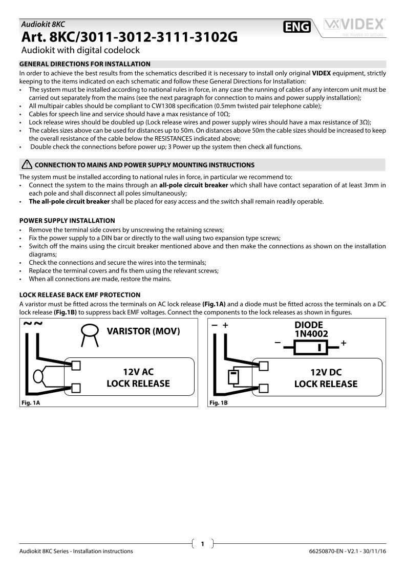
LOCK RELEASE BACK EMF PROTECTIONA varistor must be fi tted across the terminals on AC lock release (Fig.1A) and a diode must be fi tted across the terminals on a DC lock release (Fig.1B) to suppress back EMF voltages. Connect the components to the lock releases as shown in fi gures.
VARISTOR (MOV)
12V ACLOCK RELEASE
Fig. 1A
DIODE1N4002
12V DCLOCK RELEASE
Fig. 1B
ENG
66250870-EN - V2.1 - 30/11/162
Audiokit 8KC
Audiokit 8KC Series - Installation instructions
Art. 8KC/3011-3012-3111-3102G Audiokit with digital codelock
Videx Electronics S.p.A.Via del Lavoro 1, 63846 Monte Giberto (FM)Phone: +39 0734 631669 - Fax +39 0734 631669www.videx.it - [email protected]
Autore:
Data modifica:
Data creazione:Title:
Notes:
Titolo:
Note: Cod.File:
Foglio
/ 21
Marco Rongoni
8kcgeneral.dwg
06/09/2016
11/07/2016
ART.321
50/60 Hz230V
230V
12V
ART.3011-3012-3111-3102G- Citofono- Intercom- Innenstelle- Poste d'appartement- Teléfono- Telefone
ART.8836M-1- Pulsantiera con portiere elettrico- Front panel with built in audio amplifier- Aussenstelle mit Sprecheinheit- Platine de rue avec groupe phonie- Unidad de habla/Botonera con parlante- Botoneira com porteiro eléctrico
*- Regolazione volume della nota elettronica (3 livelli).- Call tone volume control (3 Levels).- Régulation du volume de l'appel électronique (sur 3 niveaux).- Lautstärkeregulierung des elektronischen Rufs (auf 3 Niveaus).- Control de volumen del tono electrónico (3 niveles)- Controle de volume (3 nÍveis) de chamada electrónica.
ART.8KC-1 / 1S3011-3012-3111-3102G
VIDEXVIDEX VIDEX
YEL
LOW
6
BLA
CK
VO
L.R
EG.
4
RED
93
GR
EEN
2 1 5 8
VIDEX
ON
OFF
+
Art.8800
Art.8836M-11
12V
SE
66250870-EN - V2.1 - 30/11/163
Audiokit 8KC
Audiokit 8KC Series - Installation instructions
Art. 8KC/3011-3012-3111-3102G Audiokit with digital codelock
Videx Electronics S.p.A.Via del Lavoro 1, 63846 Monte Giberto (FM)Phone: +39 0734 631669 - Fax +39 0734 631669www.videx.it - [email protected]
Autore:
Data modifica:
Data creazione:Title:
Notes:
Titolo:
Note: Cod.File:
Foglio
/ 22
Marco Rongoni
8kcgeneral.dwg
06/09/2016
11/07/2016
ART.321
50/60 Hz230V
230V
12V
12V
SE
ART.3011-3012-3111-3102G- Citofono- Intercom- Innenstelle- Poste d'appartement- Teléfono- Telefone
ART.8836M-2- Pulsantiera con portiere elettrico- Front panel with built in audio amplifier- Aussenstelle mit Sprecheinheit- Platine de rue avec groupe phonie- Unidad de habla/Botonera con parlante- Botoneira com porteiro eléctrico
*- Regolazione volume della nota elettronica (3 livelli).- Call tone volume control (3 Levels).- Régulation du volume de l'appel électronique (sur 3 niveaux).- Lautstärkeregulierung des elektronischen Rufs (auf 3 Niveaus).- Control de volumen del tono electrónico (3 niveles)- Controle de volume (3 nÍveis) de chamada electrónica.
264 1 3 5 8 9
To GateOverride
To Gate Trigger
Art.3102GVIDEX
ON
OFF
2 5 893164
*
ART.8KC-2 / 2S3011-3012-3111-3102G
12
+
Art.8800
Art.8836M-2
66250870-EN - V2.1 - 30/11/164
Audiokit 8KC
Audiokit 8KC Series - Installation instructions
Wiring Guide Line
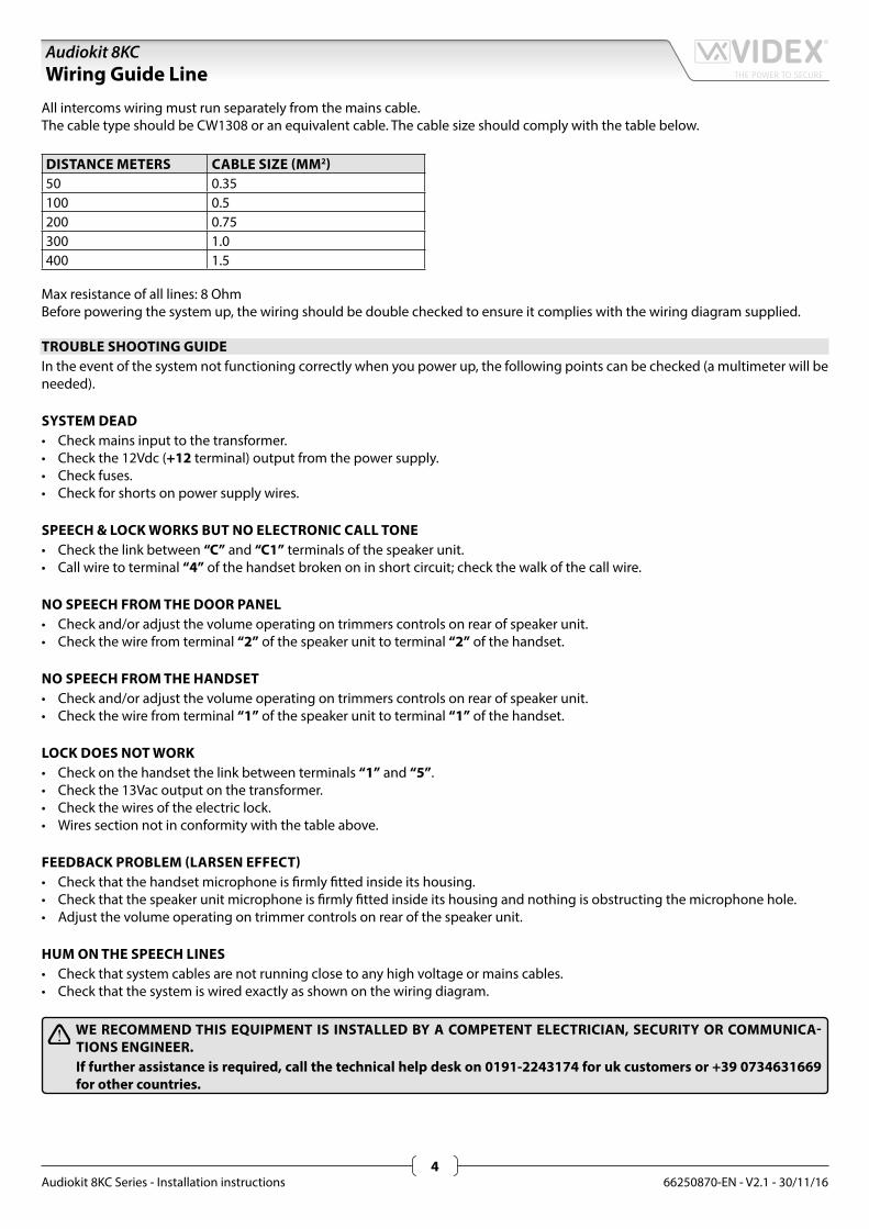
All intercoms wiring must run separately from the mains cable.The cable type should be CW1308 or an equivalent cable. The cable size should comply with the table below.
Max resistance of all lines: 8 OhmBefore powering the system up, the wiring should be double checked to ensure it complies with the wiring diagram supplied.
TROUBLE SHOOTING GUIDEIn the event of the system not functioning correctly when you power up, the following points can be checked (a multimeter will be needed).
SYSTEM DEAD• Check mains input to the transformer.• Check the 12Vdc (+12 terminal) output from the power supply.• Check fuses.• Check for shorts on power supply wires.
SPEECH & LOCK WORKS BUT NO ELECTRONIC CALL TONE• Check the link between “C” and “C1” terminals of the speaker unit.• Call wire to terminal “4” of the handset broken on in short circuit; check the walk of the call wire.
NO SPEECH FROM THE DOOR PANEL• Check and/or adjust the volume operating on trimmers controls on rear of speaker unit.• Check the wire from terminal “2” of the speaker unit to terminal “2” of the handset.
NO SPEECH FROM THE HANDSET• Check and/or adjust the volume operating on trimmers controls on rear of speaker unit.• Check the wire from terminal “1” of the speaker unit to terminal “1” of the handset.
LOCK DOES NOT WORK• Check on the handset the link between terminals “1” and “5”.• Check the 13Vac output on the transformer.• Check the wires of the electric lock.• Wires section not in conformity with the table above.
FEEDBACK PROBLEM (LARSEN EFFECT)• Check that the handset microphone is firmly fitted inside its housing.• Check that the speaker unit microphone is firmly fitted inside its housing and nothing is obstructing the microphone hole.• Adjust the volume operating on trimmer controls on rear of the speaker unit.
HUM ON THE SPEECH LINES• Check that system cables are not running close to any high voltage or mains cables.• Check that the system is wired exactly as shown on the wiring diagram.
WE RECOMMEND THIS EQUIPMENT IS INSTALLED BY A COMPETENT ELECTRICIAN, SECURITY OR COMMUNICA-TIONS ENGINEER.If further assistance is required, call the technical help desk on 0191-2243174 for uk customers or +39 0734631669 for other countries.
66250870-EN - V2.1 - 30/11/165
Audiokit 8KC
Audiokit 8KC Series - Installation instructions
INSTALLING A FLUSH MOUNTING DOOR STATION
1. Mount back box S (Fig. 2) at 165 cm from ground level (Fig. 1);2. If more than one flush box is needed, connect them by using the plastic spacers provided A (Fig. 2);3. If necessary finish and clean properly the module support fixing holes and all other holes B (Fig. 2);4. A rainshield D (Fig. 3 & 4) can be mounted using the fixing screws G (Fig. 4) to conceal possible wall finishing defects and pro-
tect against rain;
In order to prevent water ingress we highly recommend using a silicon sealant between the wall and the back box and between the wall and the rainshield D (Fig.3);
5. Remove the fixing screws H (Fig. 5) and remove the plastic cover E (Fig. 5) of the module support;6. Insert the modules F (Fig. 6) according the required configuration;7. Insert the microphone of the door unit amplifier into the microphone hole X (Fig. 7);8. Secure the modules by refitting the plastic cover E (Fig. 8) and using the screws H (Fig. 8);9. Insert the hinge I (Fig. 9) and fix it with the two screws K (Fig. 9) provided;10. Make all connections following accurately the wiring diagram provided. Check the installation and if necessary adjust speech
levels using volume controls L (Fig. 9);11. Lever the support R (Fig. 10) upwards and fix it to the back box with the screw M (Fig. 11) using an alan key P (Fig. 11);12. Conceal the screw using the plastic cover N (Fig. 11) provided.
INSTALLING A SURFACE MOUNTING DOOR STATION
Fix the surface box on the wall at a distance of 165 cm between the top of the box and the ground (Fig. 1).
In order to prevent water ingress we highly recommend using a silicon sealant between the wall and the back box J (Fig.12) and around all holes W (Fig.12).
To complete the installation follow the same steps described above for the flush box.
Note: if additional holes are made in the box or rainshield, oxidation problems may appear unless the unprotected metal is coated with a protective paint.
HOW TO REMOVE THE CARD NAME HOLDER• To avoid damage to the module front plate, tape the side that will be in contact with the screwdriver blade;• lnsert a flat screwdriver into the card-holder hole as shown in Fig. 13;• Move the screwdriver to the left as shown in Fig. 14 to extract the card name holder;• Edit the card name then replace it inside the holder and refit: insert the holder inside its housing from the left or right side then
push the other side until it clips into place.
8000 Series Surface and flush mounting door station installation
66250870-EN - V2.1 - 30/11/16
Fig. 1
S
D
G
Fig. 4
X
Fig. 7
R
Fig. 10
Fig. 13
A B
B
S
Fig. 2
E
H
Fig. 5
H
E
Fig. 8
M
P
N
Fig. 11
Fig. 14
D
Fig. 3
F
Fig. 6
L
K
I
Fig. 9
W
J
Fig. 12
6
Audiokit 8KC
Audiokit 8KC Series - Installation instructions
EXAMPLE: INSTALLING A TWO MODULE OUTDOOR STATION8000 Series surface and flush mounting door station installation
66250870-EN - V2.1 - 30/11/167
Audiokit 8KC
Audiokit 8KC Series - Installation instructions
Art. 8800 - Art. 8800-3 Digital codelock module DESCRIPTIONAccess control system with 2 codes and 2 Relay outputs for Art. 8800 (3 codes and 3 Relay outputs for Art. 8800-3).• Engineer’s code to enter into the “Programming Menu” ( from
4 to 8 digits).• Programming of the activation time of each relay from 1 up to
99 seconds or latching.• Possibility to activate relay 1 by shorting terminal ”SW1” to
GND and relay 2 by shorting terminal “SW2” to GND. Both re-lays will operate for the programmed time.
• Keypad gives an acoustic (buzzer) signal during the entering of codes and a continuous melody for 4 or more seconds, ac-cording to the number of mistakes (self protection).
• Keypad includes panel illumination and 2 LED’s to show the following:
» Correct relay code (green LED on for 2 seconds). » Red LED to indicate when in the “programming menu”.
MODELSArt. 8800: Module 2 Relay with keypad illumination LEDsArt. 8800-3: Module 3 Relay with keypad illumination LEDs
OPERATIONTo use the system, type in the programmed code and press “ENTER” , the green LED will illuminate and the relay will operate for the pro-grammed time.To cancel remain open time, type in the same code and press “CLEAR”. If a wrong code is entered, a continuous melody will sound for 4 or more seconds, according to the number of mistakes.
INITIALIZATIONWhen the installation is concluded and carried out according to the wiring diagram, power up the system and program it by following the “VX8800 PROGRAMMING” Flow Chart.
PROGRAMMINGRefer also to flow chart.• Enter “ENGINEER’S CODE”: first time type six times “1” (111111
factory preset) and press ENTER (The red LED will illuminate).• Confirm “ENGINEER’S CODE” (typing again the same) or type
the new code (4 to 8 digits) then press ENTER (Melody). Press-ing twice the ENTER button without changing the “ENGI-NEER’S CODE”, will exit from the programming.
• Enter the code (4 to 8 digits) to enable “RELAY 1” (ACCESS 1) or re-enter the existing code then press ENTER (Melody).
• Enter the “RELAY 1” operation time (2 digits 01 to 99 I.E. 05=5 seconds, 00= remain open time) or re-enter the existing time then press ENTER (Melody).
• Enter the code (4 to 8 digits) to enable “RELAY 2” (ACCESS 2) or re-enter theexisting code then press ENTER (Melody).
• Enter the “RELAY 2” operation time (2 digits 01 to 99 I.E. 05=5 seconds, 00=remain open time) or re-enter the existing time then press ENTER (Melody).
• Enter the code (4 to 8 digits) to enable “RELAY 3” (ACCESS 3 only for Art. 8800-3) or re-enter the existing code then press ENTER (Melody).
• Enter the “RELAY 3” (only for Art. 8800-3) operation time (2 digits 01 to 99 I.E. 05=5 seconds, 00=remain open time) or re-enter the existing time then press ENTER (Melody).
• The system is ready to use (the red LED will be off).
Fig. 1
ENTER THE "ENGINEER’S CODE"
CONFIRM OR CHANGE
"ENGINEER’S CODE"
ENTER"ACCESS 1 CODE"
ENTER"ACCESS 2 CODE"
ENTER"ACCESS 3 CODE"***
ENTER"ACCESS 1 TIME"
ENTER"ACCESS 2 TIME"
ENTER"ACCESS 3 TIME"***
SYSTEMREADY TO USE
First time six times 1 “111111” factory preset
Type again six times “1” or the new en-gineer’s code 4 to 8 digits
Code to enable relay 14 to 8 digits
Code to enable relay 24 to 8 digits
Code to enable relay 34 to 8 digits
Two digits (01 to 99) i.E. 05=5 Seconds00= remain open
Two digits (01 to 99) i.E. 05=5 Seconds
Two digits (01 to 99) i.E. 05=5 Seconds
Red led will be off
Press Enter(Red LED will be ON)
Press Enter(melody)
Press Enter(melody)
Press Enter(melody)
Press Enter(melody)
Press Enter(melody)
Press Enter(melody)
Press Enter(melody)
*** Only for Art. 8800-3
66250870-EN - V2.1 - 30/11/168
Audiokit 8KC
Audiokit 8KC Series - Installation instructions
Art. 8800 - Art. 8800-3 Digital codelock module
INSTRUCTION TO RETURN SYSTEM TO PRESET ENGINEER’S FACTORY CODE• Turn off power to code lock.• Keep “ENTER” button pressed while turning back on the power to the code lock.• Release “ENTER” button.• The master code is now set at factory engineer’s code “111111” (six times “1”).• Proceed with programming for a new system.
NOTES• To switch off any relay while operating, type in the relevant code then press the “CLEAR” button.• To operate relays together, set the same code for each relay.• If a wrong code is entered, the system will lock out for 5 seconds which will increase each time a wrong code is entered. The sys-
tem will operate only when the correct code is entered.
GENERAL DIRECTIONS FOR INSTALLATIONIn order to achieve the best results from the schematics described it is necessary to install only original VIDEX equipment, strictly keeping to the items indicated on each schematic and follow these General Directions for Installation:• The system must be installed according to national rules in force, in any case the running of cables of any intercom unit must be
carried out separately from the mains;• All multipair cables should be compliant to CW1308 specification (0.5mm twisted pair telephone cable.
» Cables for speech line and service should have a max resistance of 10Ω » Lock release wires should be doubled up (Lock release wires and power supply wires should have a max resistance of 3Ω);
• The cable sizes above can be used for distances up to 50m. On distances above 50m the cable sizes should be increased to keep the overall resistance of the cable below the RESISTANCES indicated above;
• Double check the connections before power up;• Power up the system then check all functions.
LOCK RELEASE BACK EMF PROTECTIONA varistor must be fi tted across the terminals on AC lock release (Fig.1A) and a diode must be fi tted across the terminals on a DC lock release (Fig.1B) to suppress back EMF voltages. Connect the components to the lock releases as shown in fi gures.
VARISTOR (MOV)
12V ACLOCK RELEASE
Fig. 1A
DIODE1N4002
12V DCLOCK RELEASE
Fig. 1B
66250870-EN - V2.1 - 30/11/169
Audiokit 8KC
Audiokit 8KC Series - Installation instructions
Art. 8800 - Art. 8800-3 Digital codelock module
RE-PROGRMMING GUIDE
Engineer’s code
Relay 1 code
Relay 2 code
Relay 3 code***
Relay 1 time
Relay 2 time
Relay 3 time***
Notes: * If the red light does not illuminate, the engineer’s code is
incorrect. Follow instructions to return system to preset en-gineer’s factory code.
** On the first loop of the flow chart its relay 1, second loop is relay 2 and third loop is relay 3.
*** Only for Art. 8800-3
ENTER THE ENGINEER’S CODE
RE-ENTER THE ENGINEER’S CODE
ENTERACCESS CODE
ENTERACCESS TIME
PRESS ENTER TWICE TO EXIT
PROGRAMMING
MORE DOORS?
Alternatively enter a new engineer’s code (4 to 8 digits)
Press Enter(Red light will illu-minate*)
Press Enter
Press Enter
Press Enter
Repeat steps for relay 2and relay 3***
YES
NO
Relay code (4-8 dig-its) operate the door or gate.**
Two digits (01-99 sec or 00 for remain open)
ART. 8800 TERMINALSSW1 Relay 1 command signal (active low)SW2 Relay 2 command signal (active low)NC2 Relay 2 normally closed contact
Max24Vac/dc
5A
NO2 Relay 2 normally open contactC2 Relay 2 common contactNC1 Relay 1 normally closed contactNO1 Relay 1 normally open contactC1 Relay 1 common contact
/+ 12/24Vac/dc power input/–
ART. 8800-3 TERMINALSNO3 Relay 3 normally open contact
Max24Vac/dc
5A
C3 Relay 3 common contactNC2 Relay 2 normally closed contactNO2 Relay 2 normally open contactC2 Relay 2 common contactNC1 Relay 1 normally closed contactNO1 Relay 1 normally open contactC1 Relay 1 common contact
/+ 12/24Vac/dc power input/–
TECHNICAL SPECIFICATIONSPower requirements: 12/24V AC/DC, 2VAPower Consumption: On AC On DC Stand-by: 82mA Stand-by: 21.5mA Operating: 125mA Operating: 35.0mAWorking Temperature: -10 +50° C
The product is CE marked demonstrating its conformity and is for distribution within all member states of the EU with no restrictions. This product follows the provisions of the European Directives 2014/30/EU (EMC); 2014/35/EU (LVD); 2011/65/EU (RoHS): CE marking 93/68/EEC.
Main UK office:VIDEX SECURITY LTD1 Osprey Trinity ParkTrinity WayLONDON E4 8TDPhone: (+44) 0870 300 1240Fax: (+44) 020 8523 [email protected]