Date / Year-Month-Day Approved Revision Document No BLUETOOTH DOC 2003-05-22 Version 1.00 Prepared e-mail address N.B. Bluetooth Audio Video Working Group [email protected]Confidential AUDIO/VIDEO DISTRIBUTION TRANSPORT PROTOCOL SPECIFICATION Version 1.0 Adopted Abstract This protocol defines A/V stream negotiation, establishment, and transmission procedures. Also specified are the message formats that are exchanged between such devices to transport their A/V streaming in A/V distribution applications. Release Date: 22 May 2003
Transcript
Date / Year-Month-Day Approved Revision Document No BLUETOOTH DOC 2003-05-22 Version 1.00 Prepared e-mail address N.B.
AUDIO/VIDEO DISTRIBUTION TRANSPORT PROTOCOL SPECIFICATION
Version 1.0 Adopted
Abstract
This protocol defines A/V stream negotiation, establishment, and transmission procedures. Also specified are the message formats that are exchanged between such devices to transport their A/V streaming in A/V distribution applications.
Release Date: 22 May 2003
BLUETOOTH SPECIFICATION Audio/Video Distribution Transport Protocol Specification Page 2 of 145
Revision History Revision Date Comments
Draft 0.95a February 2002 Updated with Internal Feedback Draft 0.95b March 2002 Release after Adoption Review Draft 1.00 May 2002 Release for Voting Draft Draft 1.00b February 2003 Release for Voting Draft Version 1.0 May 2003 Updated title and header
Release Date: 22 May 2003
BLUETOOTH SPECIFICATION Audio/Video Distribution Transport Protocol Specification Page 3 of 145
Contributors Morgan Lindqvist Ericsson
Michael Andre Intel
Tsuyoshi Okada Matsushita
Billy Brackenridge Microsoft
Jurgen Schnitzler Nokia
Kalervo Kontola Nokia
Vesa Lunden Nokia
Christian Bouffioux Philips
Emmanuel Mellery Philips
Geert Knapen Philips
Marc Vauclair Philips
Olivier Hus Philips
Rob J. Davies Philips
Shaun Barrett (Editor) Philips
Harumi Kawamura Sony
Masakazu Hattori Sony
Ruediger Mosig Sony
Ichiro Tomoda Toshiba
Junko Ami Toshiba
Takeshi Saito Toshiba
Yoshiaki Takabatake (Owner) Toshiba
Release Date: 22 May 2003
BLUETOOTH SPECIFICATION Audio/Video Distribution Transport Protocol Specification Page 4 of 145
Disclaimer and Copyright Notice The copyright in these specifications is owned by the Promoter Members of Bluetooth SIG, Inc. (“Bluetooth SIG”). Use of these specifications and any related intellectual property (collectively, the “Specification”), is governed by the Promoters Membership Agreement among the Promoter Members and Bluetooth SIG (the “Promoters Agreement”), certain membership agreements between Bluetooth SIG and its Adopter and Associate Members (the Membership Agreements”) and the Bluetooth Specification Early Adopters Agreements (“1.2 Early Adopters Agreements”) among Early Adopter members of the unincorporated Bluetooth special interest group and the Promoter Members (the “Early Adopters Agreement”). Certain rights and obligations of the Promoter Members under the Early Adopters Agreements have been assigned to Bluetooth SIG by the Promoter Members. Use of the Specification by anyone who is not a member of Bluetooth SIG or a party to an Early Adopters Agreement (each such person or party, a “Member”), is prohibited. The legal rights and obligations of each Member are governed by their applicable Membership Agreement, Early Adopters Agreement or Promoters Agreement. No license, express or implied, by estoppel or otherwise, to any intellectual property rights are granted herein. Any use of the Specification not in compliance with the terms of the applicable Membership Agreement, Early Adopters Agreement or Promoters Agreement is prohibited and any such prohibited use may result in termination of the applicable Membership Agreement or Early Adopters Agreement and other liability permitted by the applicable agreement or by applicable law to Bluetooth SIG or any of its members for patent, copyright and/or trademark infringement. THE SPECIFICATION IS PROVIDED “AS IS” WITH NO WARRANTIES WHATSOEVER, INCLUDING ANY WARRANTY OF MERCHANTABILITY, NONINFRINGEMENT, FITNESS FOR ANY PARTICULAR PURPOSE, SATISFACTORY QUALITY, OR REASONABLE SKILL OR CARE, OR ANY WARRANTY ARISING OUT OF ANY COURSE OF DEALING, USAGE, TRADE PRACTICE, PROPOSAL, SPECIFICATION OR SAMPLE. Each Member hereby acknowledges that products equipped with the Bluetooth™ technology (“Bluetooth™ Products”) may be subject to various regulatory controls under the laws and regulations of various governments worldwide. Such laws and regulatory controls may govern, among other things, the combi-nation, operation, use, implementation and distribution of Bluetooth™ Products. Examples of such laws and regulatory controls include, but are not limited to, airline regulatory controls, telecommunications regulations, technology transfer controls and health and safety regulations. Each Member is solely responsible for the compliance by their Bluetooth™ Products with any such laws and regulations and for obtaining any and all required authorizations, permits, or licenses for their Bluetooth™ Products related to such regulations within the applicable jurisdictions. Each Member acknowledges that nothing in the Specification provides any information or assistance in connection with securing such compliance, authorizations or licenses. NOTHING IN THE SPECIFICATION CREATES ANY WARRANTIES, EITHER EXPRESS OR IMPLIED, REGARDING SUCH LAWS OR REGULATIONS. ALL LIABILITY, INCLUDING LIABILITY FOR INFRINGEMENT OF ANY INTELLECTUAL PROPERTY RIGHTS OR FOR NONCOMPLIANCE WITH LAWS, RELATING TO USE OF THE SPECIFICATION IS EXPRESSLY DISCLAIMED. BY USE OF THE SPECIFICATION, EACH MEMBER EXPRESSLY WAIVES ANY CLAIM AGAINST BLUETOOTH SIG AND ITS PROMOTER MEMBERS RELATED TO USE OF THE SPECIFICATION. Bluetooth SIG reserves the right to adopt any changes or alterations to the Specification as it deems necessary or appropriate and to adopt a process for adding new Bluetooth™ profiles after the release of the Specification.
BLUETOOTH SPECIFICATION Audio/Video Distribution Transport Protocol Specification Page 5 of 145
Document Terminology
The Bluetooth SIG has adopted Section 13.1 of the IEEE Standards Style Manual, which dictates use of the words ``shall’’, ``should’’, ``may’’, and ``can’’ in the development of documentation, as follows:
• The word shall is used to indicate mandatory requirements strictly to be followed in order to conform to the standard and from which no deviation is permitted (shall equals is required to).
• The use of the word must is deprecated and shall not be used when stating mandatory requirements; must is used only to describe unavoidable situations.
• The use of the word will is deprecated and shall not be used when stating mandatory requirements; will is only used in statements of fact.
• The word should is used to indicate that among several possibilities one is recommended as particularly suitable, without mentioning or excluding others; or that a certain course of action is preferred but not necessarily required; or that (in the negative form) a certain course of action is deprecated but not prohibited (should equals is recommended that).
• The word may is used to indicate a course of action permissible within the limits of the standard (may equals is permitted).
The word can is used for statements of possibility and capability, whether material, physical, or causal (can equals is able to).
Release Date: 22 May 2003
BLUETOOTH SPECIFICATION Audio/Video Distribution Transport Protocol Specification Page 6 of 145
Contents
1 General Description ..........................................................................12 1.1 Overview ...................................................................................12 1.2 Operation Between Devices......................................................13
4 Terminology and Definitions ............................................................17 4.1 Stream.......................................................................................17 4.2 Source (SRC) and Sink (SNK) ..................................................17 4.3 Initiator (INT) and Acceptor (ACP) ............................................17 4.4 Application and Transport Service Capabilities .........................17 4.5 Services, Service Categories, and Service Parameters ............18 4.6 Media Packets, Recovery Packets, and Reporting Packets......18 4.7 Stream End Point (SEP)............................................................19 4.8 Stream Context (SC) .................................................................19 4.9 Stream Handle (SH) ..................................................................19 4.10 Stream End Point Identifier (SEID)............................................19 4.11 Stream End Point State.............................................................20 4.12 Transport Session .....................................................................20 4.13 Transport Session Identifier (TSID) ...........................................20 4.14 Transport Channel.....................................................................21 4.15 Transport Channel Identifier (TCID) ..........................................21 4.16 Reserved for Future Additiond (RFA) ........................................21 4.17 Reserved for Future Definitions (RFD) ......................................21 4.18 Forbidden (F) ............................................................................21
5.2 Interface Functionality ...............................................................23 5.3 Stream End Point Architecture ..................................................25 5.4 Transport Services ....................................................................26
5.4.1 Basic Service................................................................ 26 5.4.2 Recovery Service ......................................................... 27 5.4.3 Reporting Service ......................................................... 28 5.4.4 Adaptation Service – Multiplexing................................. 29
Release Date: 22 May 2003
BLUETOOTH SPECIFICATION Audio/Video Distribution Transport Protocol Specification Page 7 of 145
5.4.5 Adaptation Service – Robust Header Compression ..... 30 5.4.6 Transport and Signalling Channel Establishment ......... 30
6 Signalling Procedures.......................................................................32 6.1 General Requirements ..............................................................32 6.2 Transaction Model.....................................................................33 6.3 Stream Management Signalling Overview ................................34 6.4 Signal Command Set ................................................................35 6.5 State Machine Overview ...........................................................36 6.6 Stream End Point Discovery .....................................................36 6.7 Get capabilities..........................................................................37 6.8 Stream Configuration ................................................................37 6.9 Stream Get Configuration..........................................................38 6.10 Stream Establishment ...............................................................39 6.11 Stream Start ..............................................................................39 6.12 Stream Release ........................................................................40 6.13 Stream Suspend .......................................................................41 6.14 Stream Reconfigure ..................................................................42 6.15 Security Control.........................................................................42 6.16 Abort..........................................................................................42 6.17 General Reject ..........................................................................43
7 Transport Procedures.......................................................................44 7.1 General Requirements ..............................................................44 7.2 Basic Service ............................................................................44
7.2.1 Media Packet Format ................................................... 45
8 Signalling Messages .........................................................................60 8.1 Stream Configuration Procedure...............................................60 8.2 Signalling Message format ........................................................60 8.3 Signal Fragmentation ................................................................61 8.4 Signal command and response headers ...................................62
8.4.1 Transaction Label ......................................................... 62 8.4.2 Packet Type.................................................................. 63 8.4.3 Message Type .............................................................. 63 8.4.4 Signal Identifier............................................................. 63 8.4.5 Packet size requirements ............................................. 63 8.4.6 Message integrity verification at receiver side .............. 64
8.5 Signalling command set ............................................................65 8.6 Stream End Point Discovery .....................................................65
8.6.1 Stream End Point Discovery Command ....................... 65 8.6.2 Stream End Point Discovery Response........................ 65 8.6.3 Stream End Point Discovery Reject.............................. 66
8.7 Get Capabilities.........................................................................66 8.7.1 Get Capabilities Command........................................... 66 8.7.2 Get Capabilities Response ........................................... 66 8.7.3 Get Capabilities Reject ................................................. 67
8.8 Stream Configuration ................................................................67 8.8.1 Set Configuration Command ........................................ 67 8.8.2 Set Configuration Response......................................... 68 8.8.3 Set Configuration Reject............................................... 68
8.9 Get Stream configuration ..........................................................68 8.9.1 Get Configuration Command........................................ 68 8.9.2 Get Configuration Response ........................................ 68 8.9.3 Get Configuration Reject .............................................. 69
8.16 Security Control.........................................................................76 8.16.1 Security Control Command........................................... 76 8.16.2 Security Control Response ........................................... 76 8.16.3 Security Control Reject ................................................. 76
8.17 General Reject ..........................................................................76 8.18 Information Elements ................................................................77
8.18.1 Stream End-point IDentifier (SEID, INT SEID, ACP SEID)..................................................................................... 77
8.18.2 Length Of Service Capability (LOSC) ........................... 78 8.18.3 Stream End-point Type, Source or Sink (TSEP)........... 78 8.18.4 Number Of Signal Packets (NOSP).............................. 78 8.18.5 Stream End Point In Use (In Use) ................................ 78 8.18.6 Signalling Errors (ERROR_CODE)............................... 78
8.19 Service Capabilities...................................................................84 8.19.1 Generic Service Capabilities information elements ...... 85 8.19.2 Media Transport Capabilities ........................................ 86 8.19.3 Reporting Capabilities .................................................. 86 8.19.4 Recovery Capabilities ................................................... 87 8.19.5 Media Codec Capabilities ............................................. 87
Release Date: 22 May 2003
BLUETOOTH SPECIFICATION Audio/Video Distribution Transport Protocol Specification Page 10 of 145
9.5.1 INT is a SNK Device..................................................... 94 9.5.2 INT is a SRC Device..................................................... 94
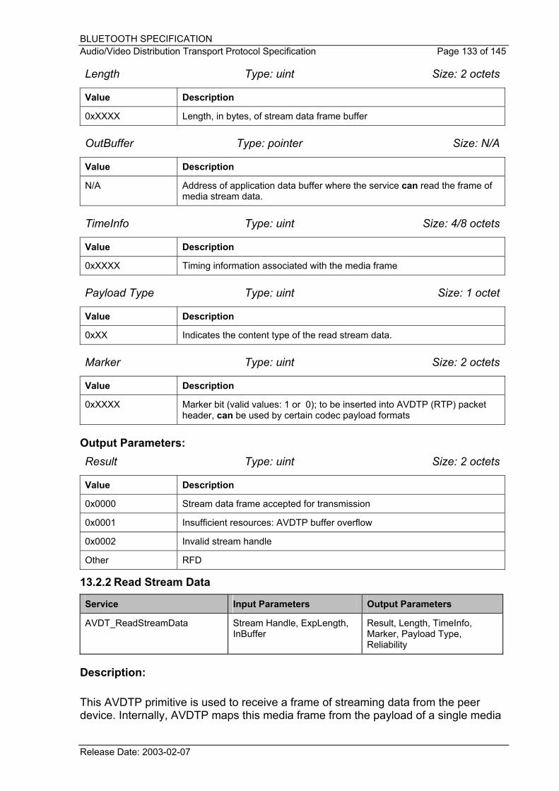
13.2 Media Transport service interface ........................................... 132 13.2.1 Write Stream Data ...................................................... 132 13.2.2 Read Stream Data...................................................... 133
14 APPENDIX B – Multiplexing Service Example (informative)........ 136 14.1 Packetisation in Basic Service Mode....................................... 136 14.2 Packetisation in Multiplexing Mode ......................................... 137
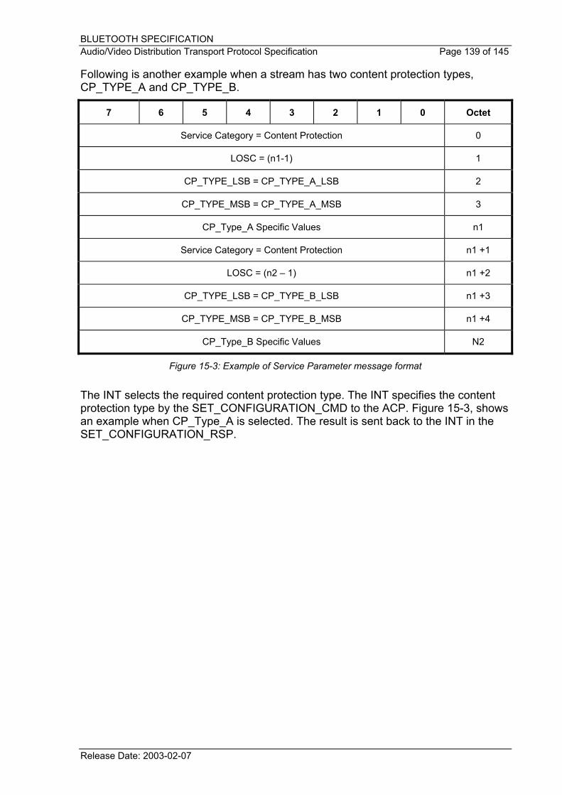
15 APPENDIX C – Content Protection Procedure (informative) ....... 138
16 APPENDIX D – Transport and Streaming Considerations (informative).......................................................................................................... 140 16.1 Synchronisation Definitions ..................................................... 140
16.2 Different clocks and Synchronisation ...................................... 142 16.3 RTP timestamp and Sequence Numbers ................................ 142 16.4 Jitter Calculations.................................................................... 143 16.5 Media Stream Service Interface .............................................. 143
17 APPENDIX E - Acronyms and Abbreviations................................ 144
Release Date: 22 May 2003
BLUETOOTH SPECIFICATION Audio/Video Distribution Transport Protocol Specification Page 12 of 145
1 General Description
1.1 Overview
This document specifies the transport protocol for audio and/or video distribution connections and streaming of audio or video media over the Bluetooth air interface. Audio and video data streams require isochronous data transmission capability. Editors' Note: The A/V WG has requested additional QoS support in the next revision of the Bluetooth data link specification. When other profiles with stringent requirements are used in conjunction with a profile relying on this protocol, the performance may be degraded due to insufficient support of QoS in the current Bluetooth specification (v1.1), which all profiles use.
The transport mechanism and message formats of the A/V Distribution Transport Protocol (hereinafter referred to as AVDTP) are based on RTP defined in [3]. [3] consists of two major protocols: RTP Data Transfer Protocol (RTP) and RTP Control Protocol (RTCP). This document, A/V Distribution Transport Protocol Specification, defines the RTP protocol usage mechanism on ACL links that apply to L2CAP connections.
Commands and responses for executing the stream set-up procedures are defined as Bluetooth specific. AVDTP defines the binary transactions between Bluetooth devices for stream set-up and media streaming for audio and video using L2CAP.
A/V streaming and stream set-up signalling are transported via L2CAP packets. A dedicated Protocol/Service Multiplexer (PSM) value is used to identify L2CAP packets that are intended for AVDTP.
Release Date: 2003-02-07
BLUETOOTH SPECIFICATION Audio/Video Distribution Transport Protocol Specification Page 13 of 145
AVDTP
LMP L2CAP L2CAP LMP
Baseband Baseband
Audio/Video Signalling
Data Link
Physical
Client side Server side
AVDTP Audio/Video Streaming Media
Figure 1-1: AVDTP and Bluetooth Protocol Stack
1.2 Operation Between Devices
AVDTP applies point-to-point signalling over a connection-oriented L2CAP channel. The L2CAP channel is set up in advance, between two devices participating in A/V stream data distribution. L2CAP channels are best suited for the support of A/V stream data distribution links. This is because L2CAP channels can be flexibly configured to enable bandwidth to be shared between A/V content streams. A/V streams are transported in pseudo-isochronous L2CAP channels. A/V signalling is also transported via L2CAP channels. Signalling provides stream discovery, configuration, establishment, and transfer control.
Release Date: 2003-02-07
BLUETOOTH SPECIFICATION Audio/Video Distribution Transport Protocol Specification Page 14 of 145
2 A/V Distribution Stack Overview
Figure 2-1 shows how AVDTP, Bluetooth protocol stack, and upper layer integrate together. AVDTP exposes three interfaces to the upper layer and two interfaces to the Bluetooth protocol stack. In order to retrieve A/V device details the upper layer uses the SDP interface, provided by the Bluetooth protocol stack. Architectural interfaces are described in Section 2.2 and architectural functionality is described in Section 2.1.
When A/V applications transport audio and/or video streams over Bluetooth links, AVDTP performs A/V parameter negotiation. Based on the result of this negotiation, A/V applications transport audio and/or video content.
HCI
L2CAP
d
AVDTP
b
UL - Upper Layer
SDP
c
a
SDP-SAP
Bluetooth CoreProtocol Stack
1 32 4
5 6
L2CAP-SAP
Figure 2-1: A/V Architecture Block Diagram
Release Date: 2003-02-07
BLUETOOTH SPECIFICATION Audio/Video Distribution Transport Protocol Specification Page 15 of 145
2.1 Architectural Functionality
With reference to Figure 2-1, the A/V architecture consists of the following architectural blocks:
Block Description
Upper Layer Upper Layer requiring AVDTP services
AVDTP Audio Video Distribution Transport Protocol
SDP Service Discovery Protocol [1]
Bluetooth Protocol Stack See [1]
Table 2-1: A/V Architectural Functionality
2.2 Architectural Interfaces
With reference to Figure 2-1, the A/V architecture exposes the following interfaces:
Interface Description
1 Service Discovery Protocol (SDP) message interface used to discover the Bluetooth attributes from a distant device.
2 Application interface used to exchange Reporting packets of the stream between two interconnected devices (QoS reporting).
3 Interface that is used to exchange signalling messages between two interconnected devices for stream set-up phases, reconfiguring and tear down streams. The purpose of this channel is to provide channel negotiation in A/V distribution applications.
4 A/V elementary media packets that transport the audio/video content over one or several L2CAP connection-oriented channels during an A/V distribution session between two Bluetooth devices. The media packet format is defined at profile level.
5 L2CAP channel allocated for AVDTP signalling. L2CAP channels are distinguished by the first level of protocol routing PSM value = AVDTP.
6 L2CAP channels allocated for AVDTP transport of Media packets, Recovery packets, and Reporting packets. L2CAP channels are distinguished by the first level of protocol routing PSM value = AVDTP.
a to d See [1]
Table 2-2: A/V Architectural Interfaces
Release Date: 2003-02-07
BLUETOOTH SPECIFICATION Audio/Video Distribution Transport Protocol Specification Page 16 of 145
3 Functional Requirements
The following capabilities have been identified as requirements of the A/V Distribution Transport Protocol.
1. AVDTP shall provide the means to discover the capabilities of the devices, as well as the means to negotiate for A/V stream set up.
2. AVDTP shall provide the mechanism to establish and tear down a stream.
3. AVDTP shall provide for the mechanism and the message formats for real-time streams, which are:
• Mechanisms to minimize the transmission delay
• Mechanisms to attach data that provides timing information required for playback of media streams on the receiver side
• Mechanisms for reporting the Quality of Service and status of transport of Media packets to application level
• Mechanisms to optimise the use of available bandwidth
4. AVDTP shall be flexible by its independent functions for use on devices of limited complexity.
5. AVDTP shall provide recovery mechanisms.
6. AVDTP shall provide mechanisms to reduce the overhead of the headers in the transport protocol
Release Date: 2003-02-07
BLUETOOTH SPECIFICATION Audio/Video Distribution Transport Protocol Specification Page 17 of 145
4 Terminology and Definitions
4.1 Stream
A stream (Bluetooth A/V Stream) represents the logical end-to-end connection of streaming media data (audio or video) between two A/V devices. Stream data is interfaced with the upper layer. The A/V transport layer provides this stream connection to the application. More strictly, streaming data is source-encoded data, as the audio or video encoder and decoder conceptually reside in the upper layer.
In a multimedia application context, a stream typically corresponds to a single media channel. Exceptions apply where multiple media channels are encoded to an aggregate bit stream; e.g., in case of joint stereo encoding.
Although a streaming connection is unidirectional, bi-directional use of the transport channel is possible in case the transport layer exchanges feedback information. A stream handle (see Section 4.9) is used to uniquely distinguish one stream.
4.2 Source (SRC) and Sink (SNK)
As the stream represents unidirectional media data, the peer devices explicitly assume the roles of either a SRC or a SNK, depending on the application.
4.3 Initiator (INT) and Acceptor (ACP)
The device that initiates a procedure is considered as the INT of this procedure. The device addressed is the procedure's ACP.
The role of INT/ACP of a stream is independent of a device's role as SRC/SNK. The INT and ACP roles in the A/V transport protocol are not to be confused with the corresponding roles in the underlying L2CAP layer.
4.4 Application and Transport Service Capabilities
The A/V transport protocol represents a scalable architecture with different support levels of mechanisms used in the transport, or services provided to the upper layer. The support levels are described by a variable set of capabilities. The ACP typically exposes its capabilities to the INT that selects a configuration. The support of certain capabilities may also be mandated by a profile.
Application Service Capabilities correspond to services provided to the application layer. These comprise of, for example, the negotiation and configuration of source codecs, content protection systems and support of media synchronization.
Release Date: 2003-02-07
BLUETOOTH SPECIFICATION Audio/Video Distribution Transport Protocol Specification Page 18 of 145
Transport Service Capabilities correspond to more specifically transport-related "services" inside the transport layer. These comprise, for example, framing and segmentation, encapsulation, reporting of delivery performance, packet loss detection, packet recovery, robust header compression, and multiplexing transport sessions to transport channels.
4.5 Services, Service Categories, and Service Parameters
These terms are related to the transactions during the negotiation phase of the stream set-up procedure. To simplify the specification of transactions, the term service may refer to both Application Service Capabilities and Transport Service Capabilities, which are thus treated equally during the negotiation.
The description of services is organized in a hierarchy of Service Categories and Service Parameters. The Service Category represents the top-level structuring element. Examples of Service Categories are media transport, reporting, media recovery, media codec, content protection, robust header compression, and multiplexing mode.
Each Service Category can comprise of one or multiple Service Parameters, which may apply various options. For example, the Service Category audio streaming may imply Service Parameter as "SBC" and its options like "Sampling Frequency " and "Channel Mode".
An implementation may not support all Service Categories, or all Service Parameters within a Service Category, or all options of a Service Parameter. A stream handle (see Section 4.9) is used to refer to a stream context.
4.6 Media Packets, Recovery Packets, and Reporting Packets
The A/V transport layer interfaces streaming media with a packet-oriented bearer. Different AVDTP packet categories can occur. Streaming media is encapsulated in Media packets (RTP packet format defined by [3]). Media packets travel downstream; i.e., from the SRC to the SNK device.
Exception: when robust header compression is used then compression-related feedback packets can also travel upstream.
Depending on the supported services, the peer AVDTP entities can exchange further information. If packet recovery is used, Recovery packets containing recovery data are sent by the SRC. Recovery packet format is specified by [4]. If QoS reporting is used, information is encapsulated in reporting packets. RTCP packet format is specified by [3]. Reporting packets containing sender reports travel downstream, whereas those containing receiver reports travel upstream.
Release Date: 2003-02-07
BLUETOOTH SPECIFICATION Audio/Video Distribution Transport Protocol Specification Page 19 of 145
4.7 Stream End Point (SEP)
The Stream End-Point (SEP) is a concept to expose available Transport Services and AV capabilities of the Application in order to negotiate a stream. The Application registers its SEPs in AVDTP in order to allow other devices to discover and connect to them. A more detailed description can be found in § 5.3
4.8 Stream Context (SC)
In the course of a stream set-up procedure, both peer devices attain a common understanding of the configuration of the streaming, including the selected services, parameters, and the transport channel assignment.
Conceptually, a stream context exists in both end-points of a stream. Being associated to a single stream, the stream context, which could be seen as a kind of table, serves to collect and maintain all of this information. It is important that the stream contexts in both devices remain consistent and synchronized.
4.9 Stream Handle (SH)
A Stream Handle (SH) represents a top-level reference to a stream. The stream handle is exposed to the application layer, especially on the Upper Streaming Interface and the Reporting Interface. Moreover, the stream handle refers to the stream context associated with that stream.
The stream handle is a device-local identifier. It is independently assigned by the AVDTP entities of the INT and the ACP during the establishment of the stream connection. The scope of the stream handle is not local to a connection to a specific peer device (not connection-local). The stream handle is never exchanged on the air interface.
4.10 Stream End Point Identifier (SEID)
In contrast to the stream handle, the Stream End-Point Identifier (SEID) represents a cross-device reference to a specific stream. This reference is used in the signalling transactions; i.e., on the air interface, between the peer AVDTP entities.
A SEID is assigned at application level, of a device that responds to a stream discovery procedure. Here, the responding device exposes its basic stream end-points and basic capabilities, audio/video, SNK/SRC, and assigns the SEID as a unique reference for the further transactions. To prevent conflicts, the scope of the SEID shall be both device-local and connection-local. The application is responsible for assigning a SEID, which is not in use on the connection to the same peer device.
In the course of a stream set-up procedure, both AVDTP entities create the association between the local SEID and the local Stream Handle and typically store it
Release Date: 2003-02-07
BLUETOOTH SPECIFICATION Audio/Video Distribution Transport Protocol Specification Page 20 of 145
in the Stream Context. Both SEID and Stream Handle appear on the Upper Signalling Interface.
Note: A unique mapping exists in each AVDTP entity between the Stream Handle and the pair of remote device address and SEID.
4.11 Stream End Point State
Various operations and transactions apply to a stream. A state machine is related to each stream and serves to control these operations. Aspects influencing the Stream State are, for example, if the negotiation procedure is in progress or complete, if transport channels are being established and assigned, if applications are expected to send or receive data on an available stream connection.
4.12 Transport Session
Internally to the A/V transport layer, a stream can be decomposed into one, two, or three transport sessions, which exist between the peer AVDTP entities. Each transport session can be used for only one AVDTP packet category, which means Media, Recovery, or Reporting packets.
Thus, each stream connection comprises at least one-transport session containing Media packets. If packet recovery (RTP-FEC) is supported on a stream connection, another transport session contains the recovery packets. If QoS reporting (RTCP) is supported on a stream connection, another transport session contains the Reporting packets. A Transport Session Identifier (TSID, see Section 4.13) is used to refer to a transport session.
4.13 Transport Session Identifier (TSID)
The Transport Session Identifier (TSID) represents a reference to a Transport Session. Only in case of the Multiplexing Mode, the TSID is exchanged on the air interface (as part of the Media, Recovery, or Reporting packet header). In other terms, if the Multiplexing Mode is not configured on a stream connection, the TSID is not explicitly used.
The TSID is a cross-device reference, though its scope is connection-local. It is assigned by the AVDTP entity of the INT and shall be adopted by the AVDTP entity of the ACP.
The association of the contents type of a specific Transport Session (either Media, Recovery, or Reporting packets) is signalled by the INT during the stream establishment procedure. After that, the association is maintained in the Stream Context of both devices.
Release Date: 2003-02-07
BLUETOOTH SPECIFICATION Audio/Video Distribution Transport Protocol Specification Page 21 of 145
4.14 Transport Channel
The notion of a Transport Channel means an abstraction of the bearer underlying the A/V transport layer. For the time being, a transport channel always corresponds to an L2CAP channel (with a PSM indicating AVDTP).
If the AVDTP Multiplexing Mode is not supported, a transport channel carries packets of only one transport session. If Multiplexing Mode is configured, a transport channel can carry packets belonging to different transport sessions (of the same or different streams). A Transport Channel Identifier (TCID, see Section 4.15) is used to refer to a Transport Channel.
4.15 Transport Channel Identifier (TCID)
The Transport Channel Identifier (TCID) represents a reference to a Transport Channel. Only in the case of the Multiplexing Mode, the TCID is exchanged on the air interface (during the stream establishment transactions). In other terms, if the Multiplexing Mode is not configured on a stream connection, the TCID is not explicitly used.
The TCID is uniquely related to one underlying L2CAP channel and its local channel identifier (LCID) of the connected L2CAP channel. In contrast to the LCID though, the TCID is a cross-device reference, though connection-local.
In the Multiplexing Mode, the TCID shall be used during the stream configuration transaction to signal the mapping of Transport Sessions to Transport Channels.
4.16 Reserved for Future Additiond (RFA)
Bits with this designation shall be set to zero. Receivers shall ignore these bits.
4.17 Reserved for Future Definitions (RFD)
These bit value combinations or bit values are not allowed in the current specification but may be used in future versions. The receiver shall check that unsupported bit value combination is not used.
4.18 Forbidden (F)
This bit field combination is not allowed in the specification. The receiver shall check that this bit field combination is not used.
Release Date: 2003-02-07
BLUETOOTH SPECIFICATION Audio/Video Distribution Transport Protocol Specification Page 22 of 145
5 Architecture
Figure 5-1 shows the internal architecture of the AVDTP. The architecture includes block and interface functionality. This scope of this specification only deals with the shaded blocks highlighted in Figure 5-1.
UL - Upper Layer
Signalling
Adaptation Layer
1
L2CAP
Recovery
8 9
5
4 7
Stream Manager
6
2 3Stream Handle
(SH)
Transport SessionIdentifier
(TSID)
TCID
Local ChannelIdentifier
(LCID)
L2CAP ChannelIdentifier
Figure 5-1: AVDTP Architecture
5.1 Block Functionality 5.1.1 Stream Manager
The stream manager provides the following functionality:
• Streaming
• Media framing
• Time stamp management
Release Date: 2003-02-07
BLUETOOTH SPECIFICATION Audio/Video Distribution Transport Protocol Specification Page 23 of 145
• Media packet sequence numbering
• Reporting of packet loss to peer and to higher layer
• Jitter calculation
5.1.2 Recovery
Recovery is based on [4] and offers the following options:
• No FEC
• Equal FEC
5.1.3 Adaptation Layer
Adaptation layer offers the following functionality:
• Header Compression using Robust Header Compression [5]
• Multiplexing mode to allow several transport sessions (TSID) to be multiplexed on one transport channel (TCID)
5.2 Interface Functionality Interface Description
1
Provides:
• Application Service Capabilities Discovery
• Transport Service Capabilities Discovery
• Stream Negotiation
• Stream Establishment
• Stream Destruction
• Stream Suspend and Resume
2
Provides:
• Media Streaming
• Timing information relative to streams
3 Provides:
• QoS reporting for media streams
Release Date: 2003-02-07
BLUETOOTH SPECIFICATION Audio/Video Distribution Transport Protocol Specification Page 24 of 145
Interface Description
4
Provides, if the stream is SRC:
• Media payload plus timing information
• Primitives to report packet loss
Provides, if the stream is SNK:
• Media payload plus sent and received timing information
5 Media transport framing
6 Recovery transport framing
7 Reporting
8 L2CAP channel for signalling entity
9 L2CAP channels for transport entity
Sections 5.4.1 to 5.4.5 show the configuration modes of the AVDTP. Configuration options are negotiated at set up time of an A/V service.
Release Date: 2003-02-07
BLUETOOTH SPECIFICATION Audio/Video Distribution Transport Protocol Specification Page 25 of 145
5.3 Stream End Point Architecture
An A/V device may provide one or several streaming resources, which means sources or sinks of media streams. Conceptually an end-point (source or sink) of a stream connection resides in the application layer of a device. However, end-points are represented in the AVDTP layer for negotiating and operating a stream. As shown in Figure 5-2, AVDTP uses the concept of abstract Stream End Points (SEPs) that represent the resources and capabilities of a device.
Device A
BB
/L2C
AP
App
licat
ion
Laye
rA
VDTP
SEP u SEP v
Device B
BB
/L2C
AP
App
licat
ion
Laye
rA
VDTP
SEP x SEP zSEP y
Bluetoothair interface
Figure 5-2: Stream End Point Architecture
Assume for example that device A has 2 SEPs labelled u and v, where SEP u represents a video sink, SEP v an audio sink. Device B has three SEPs labelled x, y, and z, which represent audio sources. Device A is supposed to set up an audio stream connection with one of the audio sources in Device B.
Both Device A and Device B maintain local Stream End Point Identifiers (SEID, see section 4.10) for their SEPs, respectively. First Device A uses an AVDTP service to discover the resources of the peer device. From this procedure, Device A learns the (Device B local) SEIDs and type of media (here: audio sources) for the three SEPs in Device B. In the sequel, Device A uses another AVDTP service to collect the Application and Transport Service Capabilities for one of the remote SEPs, say for SEP z. During this transaction, Device B refers to SEP z by the SEID that Device B presented before. After knowing all the capabilities, which B has exposed, and comparing it to its own local capabilities, Device A can use yet another AVDTP
Release Date: 2003-02-07
BLUETOOTH SPECIFICATION Audio/Video Distribution Transport Protocol Specification Page 26 of 145
service to configure the stream connection. Note that the assessment and decision how to select the services occurs in the application layer of Device A, thus outside AVDTP. The existence of a local SEP v (with own local SEID), which has matching capabilities and thus can be connected with Device B’s SEP z, is implicitely assumed. Consequently, the AVDTP entity of Device A does not need to know the capabilities of local SEP v. By starting the configuration procedure though, Device A implicitly acknowledges that it has matching capabilities in a local SEP and maps the local SEP v (with local SEID) to the remote SEP z (with remote SEID), such that both devices know the respectively remote SEID for future mutual reference. On successful termination of the configuration procedure, resources in both Device A and Device B shall be allocated (locked), and neither SEP v in Device A nor SEP z in Device B could be configured for another stream connection e.g. by a third device.
Note that although both devices conceptually have SEPs, their relation follows an asymmetrical client-server model, where the application uses AVDTP services to manage streaming resources in the remote device. Device B exposes all of its capabilities to Device A, but Device A does not expose its capabilities to Device B. In subsequent signalling procedures, the stream connection shall be referenced by the SEID of the remote Device. In Device A, a local SEP (resource) necessarily exists and has capabilities that are sufficient to establish an interoperable streaming connection.
A state machine belongs to each Stream Endpoint and is present within the AVDTP layer. All state changes that are significant to the application shall be exposed through the upper interface.
5.4 Transport Services 5.4.1 Basic Service
When AVDTP is configured for Basic Service, Signalling and Stream Manager are the only active entities, as shown in Figure 5-3.
Release Date: 2003-02-07
BLUETOOTH SPECIFICATION Audio/Video Distribution Transport Protocol Specification Page 27 of 145
AdaptationServices
Signalling
L2CAP
Stream Manager
Recovery
Media(RTP)
Media(RTP)
Discovery,Negotiation,Connection Media Streams
LocalServicesControl Events
AdaptationServices
Signalling
Stream Manager
Recovery
Media(RTP)
Media(RTP)
Discovery,Negotiation,Connection Media Streams
LocalServicesControl Events
Figure 5-3: AVDTP Basic Service
The AVDTP basic service ensures the transport of Media packets of each session over individual transport channels. The service offers an appropriate interface that enables applications to stream in/out packet units that fit the maximum size requirements of the transport channel. This packet size limitation is returned to the application when the channel has been successfully configured.
5.4.2 Recovery Service
When AVDTP is configured to use Recovery Service, the recovery entity becomes active in addition to Basic Service and other configured services, shown in Figure 5-4.
AdaptationServices
Signalling
L2CAP
Stream Manager
Recovery
Media(RTP)
Media(RTP)
Discovery,Negotiation,Connection Media Streams
LocalServicesControl Events
Media-Recovery
(RTP-FEC)
AdaptationServices
Signalling
Stream Manager
Recovery
Media(RTP)
Media(RTP)
Discovery,Negotiation,Connection Media Streams
LocalServicesControl Events
Media-Recovery
(RTP-FEC)
Figure 5-4: AVDTP Recovery Service
Release Date: 2003-02-07
BLUETOOTH SPECIFICATION Audio/Video Distribution Transport Protocol Specification Page 28 of 145
The recovery service uses media packets of one transport session at the SRC side to generate additional coded packets; these recovery packets can be used at the SNK side to reconstruct original Media packets that have been lost on the air transmission path.
This service is specifically useful in applications that have huge bandwidth requirements and limited retransmission capabilities. In contrast to the baseband FEC, the recovery service implements a flexible on-demand error correction mechanism: applications get full control of service operation with respect to the channel condition and can decide to only cover the most sensible parts of the media stream. The service performs independently of the baseband packet type and is selectable for each active transport session.
To combat interference efficiently all Recovery packets are conveyed through a separate transport channel.
5.4.3 Reporting Service
When AVDTP is configured to use Reporting Service, the reporting interface becomes active in addition to Basic Service and other configured services, shown in Figure 5-5.
AdaptationServices
Signalling
L2CAP
Stream Manager
Recovery
Discovery,Negotiation,Connection Media Streams
LocalServicesControl Events
AdaptationServices
Signalling
Stream Manager
Recovery
Discovery,Negotiation,Connection Media Streams
LocalServicesControl Events
ReportingReporting
Figure 5-5: AVDTP Reporting Service
When switched on, the reporting service provides statistical information to the local application and to the remote device about time alignment of the media streams and packet losses. These reports are used to achieve appropriate media streams synchronization and/or to adapt the error concealment strategy of the applications.
The reporting service can be configured one-way (from SNK to SRC or SRC to SNK) or both-ways, depending on application requirements. The service interface allows
Release Date: 2003-02-07
BLUETOOTH SPECIFICATION Audio/Video Distribution Transport Protocol Specification Page 29 of 145
the application to adjust the periodicity of the reports and to activate/deactivate the service according to the context.
The reporting service can use an independent transport channel to transmit Report packets to the remote side.
5.4.4 Adaptation Service – Multiplexing
In the Multiplexing Mode, multiple transport sessions, belonging to the same or to a different stream, can share a common transport (L2CAP) channel. Moreover, an L2CAP packet can contain multiple packets belonging to the same or different transport sessions. An encapsulation header is therefore needed for each Media/Reporting/Recovery packet. A TSID contained in this header allows for correct routing of the packet at the SNK device.
During the Stream Configuration procedure, the INT has assigned TSIDs and TCIDs and communicated them to the ACP. To avoid conflicts in a multi-device configuration and to reduce its width, the scope of the TSID and TCID is restricted to the connection between a pair of devices. The Stream Establishment procedure does not necessarily open a new transport (L2CAP) channel. Instead, it can map a new transport session to an existing L2CAP channel. This is achieved by referencing an existing TCID.
Key: *L2CAP Channels Support Bi-directional Traffic
Figure 5-6: AVDTP Adaptation Service Option
Release Date: 2003-02-07
BLUETOOTH SPECIFICATION Audio/Video Distribution Transport Protocol Specification Page 30 of 145
The Multiplexing Mode functionality resides in the Adaptation Services layer of AVDTP. It takes effect only at the time the stream is established, and does not affect the Stream End-point concept and the organization of stream and session as exposed to the upper layer.
In the case the Media packet size exceeds the MTU requirement of the transport channel the Multiplexing mode can be configured with an optional fragmentation service to transmit the Media packet into smaller chunks to fit the transport channel requirements. If the fragmentation service of the Multiplexing mode is supported on the stream connection, the INT may select this feature as an alternative to the Media packet fragmentation at application level. The Media packet fragmentation performs automatically during the streaming provided it has been configured before the stream is open.
5.4.5 Adaptation Service – Robust Header Compression
Robust Header Compression is a Transport Service that reduces the overhead that the headers of the Media packets and Recovery packets introduce. This mechanism is fully selectable by the application, but the same configuration shall be set-up at both sides of the connection for each stream to be established. The Robust Header Compression mechanism allows the use of a feedback channel, which is negotiated at the time the media stream is configured.
5.4.6 Transport and Signalling Channel Establishment
Up to four L2CAP channels can be required between two devices participating in a streaming connection. Because L2CAP signalling does not provide the correct information to distinguish which L2CAP channel is intended for a specific transport channel, rules are set out as to the L2CAP channel establishment order.
Figure 5-7, shows the priority order of establishment for L2CAP channels. The numbers represent the priority order of the channel establishment.
Device A Device B
UL AVDTP AVDTP ULL2CAP L2CAP
L2CAP Signalling Channel Establishment [1]
L2CAP Media Transport Channel Establishment [1]
L2CAP Reporting Channel Establishment [1]
L2CAP Recovery Channel Establishment [1]
1
2
3
4
Prio
rity
Figure 5-7: Transport and Signalling Channel Establishment
Release Date: 2003-02-07
BLUETOOTH SPECIFICATION Audio/Video Distribution Transport Protocol Specification Page 31 of 145
The signalling channel (1) is only established once between two streaming devices.
Media, Reporting and Recovery Transport channels are established on a per stream basis. The priority order of the channel establishment is depicted in Figure 5-7. The numbers dictate the order of priority. If a stream only requires Media and Reporting services, and the Signalling channel is already established, the Media Transport (Basic Service) shall be the first Transport Channel to be established and the next one shall be the Reporting Transport Channel. Similarly, if a stream only requires Media Transport (Basic Service) and Recovery Service then the order of channel establishment shall start with the Media Transport Channel then the Recovery Transport Channel shall be established. If however, the Signalling Channel is not established, and a stream requires all Transport Services, the first channel to be established shall be the Signalling Channel followed by the Media Transport Channel the Reporting Transport Channel and then the Recovery Transport Channel.
Release Date: 2003-02-07
BLUETOOTH SPECIFICATION Audio/Video Distribution Transport Protocol Specification Page 32 of 145
6 Signalling Procedures
6.1 General Requirements
Signalling procedures require an ACL link between a pair of interconnected devices. Transactions are performed on a connection-oriented channel established between communicating devices, and consist of bi-directional asynchronous message exchanges.
An L2CAP channel is used for signalling and is established and released by L2CAP signalling commands. A specific Protocol/Service Multiplexer (PSM) value is allocated for AVDTP transactions handled by L2CAP.
Release Date: 2003-02-07
BLUETOOTH SPECIFICATION Audio/Video Distribution Transport Protocol Specification Page 33 of 145
6.2 Transaction Model
AVDTP follows the transaction model defined in L2CAP (see Section 3 of L2CAP in the Bluetooth Core Specification).
Device A Device B
AVDT_Signal_Req
AVDT_Signal_Ind
AVDT_Signal_Rsp
UL AVDTP AVDTP UL
AVDT_Signal_Cfm
AVDTP_Signal_CMD
AVDTP_Signal_RSP
RTX_SIG_TIMER
Figure 6-2: Transaction Model of AVDTP Command/Response
Figure 6-2 shows a message sequence chart (MSC) to illustrate the normal sequence for signalling events. The two outer vertical lines represent AVDTP signalling entities within the INT and the ACP. When AVDT_Signal_Req is sent from the upper layer (UL), the AVDTP of the INT sends AVDTP_SIGNAL_CMD to the AVDTP of the ACP. After receiving AVDTP_SIGNAL_CMD, the AVDTP of the ACP passes AVDT_Signal_Ind to its upper layer (UL). When the upper layer has dealt with AVDT_Signal_Ind, an AVDT_Signal_Rsp is sent back to AVDTP layer. This produces an AVDTP_SIGNAL_RSP back to the AVDTP of the INT. After receiving AVDTP_SIGNAL_RSP, the AVDTP of the INT signals back to the upper layer in the form of an AVDT_Signal_Cfm.
• AVDT_Signal_Req: from upper layer to a remote device
• AVDT_Signal_Cfm: confirm the request from a remote device to upper layer
• AVDT_Signal_Ind: indicate the request has been received from a remote device to upper layer
• AVDT_Signal_Rsp: respond from upper layer to a remote device.
A Response Timeout eXpired (RTX_SIG_TIMER, specified by Profiles) timer is used to terminate the signalling when the remote side is unresponsive to the signalling request.
Release Date: 2003-02-07
BLUETOOTH SPECIFICATION Audio/Video Distribution Transport Protocol Specification Page 34 of 145
6.3 Stream Management Signalling Overview
Figure 6-3 shows an overall procedure to manage a stream connection. Either or both devices may initiate a stream, consisting of the Stream Configuration procedure, Stream Establishment procedure, and the Stream Start procedure.
The Stream End Point Discovery procedure, marked as optional here, serves to return the type and identifier (SEID) for one stream end-point, or jointly for multiple stream end-points. Since the SEID is needed as a reference in the following procedures, the Discovery procedure shall have been triggered before hand. However, the Discovery procedure is not needed for each individual stream end-point, or for example, repeated configuration attempts.
Device A Device B
UL AVDTP AVDTP UL
Stream End Point Discovery
Get Capabilities Procedure
Stream Configuration Procedure
Stream Establishment Procedure
Stream Start Procedure
Stream Suspend Procedure
Stream Reconfigure Procedure
Stream Release Procedure
Figure 6-3: Stream End-point Discovery to Stream Release
The Get Capabilities procedure is also optional, as an INT may “guess” the capabilities of an ACP and directly try the Stream Configuration procedure. The Get Capabilities procedure can be triggered by any of the devices and is without effect on the stream end-point states. Nevertheless, since prior to the Stream Configuration there does not exist any resource reservation, and thus relation between peer stream end-points, the device triggering the Get Capabilities procedure shall have triggered a Discovery procedure to retrieve a SEID for reference earlier. Moreover, because of the Stream Configuration procedure, both devices know the mapping of the local and remote SEP by the corresponding pair of local and remote SEIDs and there exists a dedicated relationship between peer stream end-points in both devices.
Release Date: 2003-02-07
BLUETOOTH SPECIFICATION Audio/Video Distribution Transport Protocol Specification Page 35 of 145
Only the INT of a Stream Configuration procedure may be the INT of the Establishment and Start procedures that normally follow to perform streaming over the configured SEP. After the Start procedure has completed however, both devices may trigger any of the Stream Suspend, Stream Reconfigure, or Stream Release procedures. In those transactions, the initiating device refers to the SEID of the remote SEP, which means that the SEID used in the signalling messages depends on which device is the INT of the procedure.
A regular termination of a stream always involves a Stream Release procedure. The use of the Stream Suspend and the Stream Reconfigure procedure depends on the application. However, a Stream Suspend procedure shall precede a Stream Reconfigure procedure.
A Security Control procedure is also defined for content protection. How to use this procedure is defined by each control protection method.
6.4 Signal Command Set
The following table shows the signalling command set defined for AVDTP. Details for information elements can be found in section 8.
Command Description
AVDTP_DISCOVER Discover Stream End-points supported within a device.
AVDTP_GET_CAPABILITIES Get the capabilities of a Stream End-point (SEP).
AVDTP_SET_CONFIGURATION Set the Configuration of a SEP.
AVDTP_GET_CONFIGURATION Get the current Configuration of a SEP.
AVDTP_RECONFIGURE Request that a SEP be Reconfigured.
AVDTP_OPEN After successful configuration of a SEP, this signal is used to open the stream.
AVDTP_START
This signal has two purposes, these are:
• Once a stream has been opened, this signal is used to start the streaming.
• When a stream has been suspended, this signal is used to restart the streaming.
AVDTP_CLOSE Request the closure of a SEP.
AVDTP_SUSPEND Request that a SEP be suspended.
AVDTP_SECURITY_CONTROL Exchange content protection control data.
AVDTP_ABORT The abort signal is used to recover from error conditions.
Release Date: 2003-02-07
BLUETOOTH SPECIFICATION Audio/Video Distribution Transport Protocol Specification Page 36 of 145
6.5 State Machine Overview
Idle Configured Open Streaming Closing
Aborting
Figure 6-4 : AVDTP State Machine Overview
This section provides an overview of the Stream End Point State Machine. For a definition and detailed description of the different states see section 9.
When the ACP rejects an INT command, it shall complete the procedure by falling back to the initial state of this (local) procedure. On receipt of a reject from the ACP side the INT shall complete the procedure by falling back to the initial state of this (local) procedure.
6.6 Stream End Point Discovery
An A/V stream on a Bluetooth link is sent or received by Bluetooth devices via an abstract Stream End Point (SEP), which is referenced by a Stream End Point Identifier (SEID). A device can discover the SEPs of the remote device; i.e., potential SRC(s) and/or SNK(s) of streaming connections, by the Stream End Point Discovery procedure. The result of this procedure provides a list of SEPs along with the media types that the remote device supports.
Release Date: 2003-02-07
BLUETOOTH SPECIFICATION Audio/Video Distribution Transport Protocol Specification Page 37 of 145
AVDTP_DISCOVER_CMD(...)
INT ACP
AVDT_Discover_Req
UL AVDTP AVDTP UL
AVDT_Discover_Cfm
AVDT_Discover_Ind
AVDT_Discover_RspAVDTP_DISCOVER_RSP(...)
Figure 6-5: Stream End Point Discovery Procedure
6.7 Get capabilities
Using the SEID as a reference, the local device can query the service capabilities of the remote SEP using the Get Capabilities Procedure. If a SEP is already in use by another stream connection, the Discovery and Get Capabilities procedures may or may not yield valid entries for this SEP.
By referencing both the local and the remote SEID, the local device (the INT) configures the SEP of the remote device (the ACP) using the Set Configuration procedure. If a SEP is in use by another stream connection, the configuration procedure shall fail and yield an error indication. After a successful configuration, the stream connection can be established.
The INT configures a remote SEP by conceptually creating one, two, or three transport sessions associated with this SEP. The first transport session is always used for transporting Media packets of the stream. If the reporting (recovery) option is configured for this stream, another transport session is opened for Reporting (Recovery) packets. A transport session shall be referenced by a Transport Session Identifier (TSID) if the Stream End Point is also configured to operate in multiplexing mode.
Release Date: 2003-02-07
BLUETOOTH SPECIFICATION Audio/Video Distribution Transport Protocol Specification Page 38 of 145
Especially for the AVDTP service interface, it is impractical to refer to a stream connection by the pair of a remote device address and the (connection-local) SEID. A device-local Stream Handle is assigned by AVDTP instead and, in each device, this local Stream Handle is returned to the application during the Stream Configuration procedure.
When the multiplexing mode is configured, explicit Transport Channels Identifiers (TCIDs) are associated to the Transport Sessions Identifiers (TSIDs) for an appropriate channel mapping during the Stream Establishment procedure.
A device can initiate a Stream Get Configuration procedure to retrieve the last capabilities settings performed by the remote device on the SEP identified by the addressed SEID. The addressed Stream End Point shall have been previously configured for streaming between the peer devices. Hence, the procedure shall fail when the addressed SEP is in Idle, Closing or Aborting state.
BLUETOOTH SPECIFICATION Audio/Video Distribution Transport Protocol Specification Page 39 of 145
6.10 Stream Establishment
Device A (INT) Device B (ACP)
UL AVDTP AVDTP UL
AVDT_Open_Req
AVDT_Open_Ind
AVDTP_OPEN_RSP(...)
AVDT_Open_Cfm
AVDT_Open_Rsp
Establish L2CAP Channels for TCID(s) see [1]
OPEN
CONFIGURED
AVDTP_OPEN_CMD(...)
Figure 6-9: Stream Establishment Procedure
The opening of a transport session, while referencing the remote SEID, includes, if necessary, the establishment of a new Transport Channel.
When the multiplexing mode is not configured, a new L2CAP channel is always established and uniquely mapped to that transport session. In this mode neither Transport Session Identifiers (TSIDs) nor Transport Channel Identifiers (TCIDs) are explicitly needed to establish the connection: each device can unambiguously and implicitly associate each transport session to its own transport (L2CAP) channel according to the rules of section 5.4.6.
When the multiplexing mode is configured, explicit Transport Channels Identifiers (TCIDs) have already been associated to the Transport Sessions Identifiers (TSIDs) during the Stream Configuration procedure. In case a transport channel does not yet exist, new L2CAP channel(s) is(are) established and associated with the relevant TCIDs.
6.11 Stream Start
After the Stream Establishment is complete, the Start Streaming procedure causes the streaming to start; i.e., Media (Reporting, Recovery) packets can be exchanged. The Start Streaming procedure can be initiated by either device participating in a streaming connection.
Release Date: 2003-02-07
BLUETOOTH SPECIFICATION Audio/Video Distribution Transport Protocol Specification Page 40 of 145
Device A (SRC) Device B (SNK)
AVDTP_START_CMD(...)
UL AVDTP AVDTP UL
AVDT_Start_Req
AVDT_Start_Cfm
STREAMING
OPEN
AVDT_Start_Ind
AVDTP_START_RSP(...)
AVDT_Start_Rsp
STREAMING
Figure 6-10: Stream Start Procedure, Device A is a Source Device
Figure 6-10 and Figure 6-11 show the Start Streaming procedure. The state of the SEP is dependent upon whether the device is SNK or SRC.
Device A (SNK) Device B (SRC)
AVDTP_START_CMD(...)
UL AVDTP AVDTP UL
AVDT_Start_Req
AVDT_Start_Cfm
STREAMING
OPEN
AVDT_Start_Ind
AVDTP_START_RSP(...)
AVDT_Start_Rsp
STREAMING
Figure 6-11: Stream Start Procedure, Device A is a Sink Device
6.12 Stream Release
Stream release is initiated by the upper layer within a device; a signal is sent indicating that a stream end-point be closed. The stream end-point is identified by its remote SEID.
Release Date: 2003-02-07
BLUETOOTH SPECIFICATION Audio/Video Distribution Transport Protocol Specification Page 41 of 145
Device A (INT) Device B (ACP)
AVDTP_CLOSE_CMD(...)
UL AVDTP AVDTP UL
AVDT_Close_Req
AVDT_Close_Cfm
CLOSING
OPEN / STREAMING
AVDT_Close_Ind
AVDTP_CLOSE_RSP(...)
AVDT_Close_Rsp
CLOSING
IDLE
Release L2CAP Channels for TCID(s) see [1]
Figure 6-12: Stream Release Procedure
The device that initiates the stream release becomes the INT of the procedure. When the ACP receives the indication that a stream end-point is to be released, the ACP releases all the resources allocated to the stream end-point. This includes buffer resources, etc. After the INT receives a confirmation that the stream end-point has been released, the INT releases all the transport channels and resources allocated to the stream end-point.
6.13 Stream Suspend
Figure 6-13 shows the stream suspend procedure. The device that initiates the procedure becomes the INT.
Device A (INT) Device B (ACP)
AVDTP_SUSPEND_CMD(...)
UL AVDTP AVDTP UL
AVDT_Suspend_Req
AVDT_Suspend_Cfm
STREAMING
AVDT_Suspend_Ind
AVDTP_SUSPEND_RSP(...)
AVDT_Suspend_Cfm
OPEN
OPEN
Figure 6-13: Stream Suspend Procedure
Assume the upper layer within the INT requests that a stream (given e.g. by a stream handle) is to be suspended; A command is sent to the ACP referencing the remote
Release Date: 2003-02-07
BLUETOOTH SPECIFICATION Audio/Video Distribution Transport Protocol Specification Page 42 of 145
SEID for that stream. After the ACP has suspended its SEP, a response is sent back to the INT, which in turn suspends its SEP.
6.14 Stream Reconfigure
Figure 6-14 shows the procedure to reconfigure a stream. The first step is to perform a Suspend Streaming Procedure. When the stream is successfully suspended, a reconfigure command is used to change current capability settings. When the stream is successfully reconfigured, the stream is restarted using the Start Streaming Procedure.
Device A (INT) Device B (ACP)
AVDTP_RECONFIGURE_CMD(...)
UL AVDTP AVDTP UL
AVDT_ReConfigure_Req
AVDT_ReConfigure_Cfm
AVDT_ReConfigure_Ind
AVDTP_RECONFIGURE_RSP(...)
AVDT_ReConfigure_Rsp
Stream Suspend Procedure
Stream Start Procedure
Figure 6-14: Stream Reconfigure Procedure
6.15 Security Control If AV data transmitted over a Bluetooth link requires protection, a content protection method can be invoked. Several content protection methods are available and AVDTP signalling has a capability of negotiating content protection type. The procedure of exchanging content protection control data is composed of the following.
Because AVDTP is typically used on unreliable channels, signalling messages can be lost due to L2CAP Flush Timeouts. To react to inconsistencies between the INT
Release Date: 2003-02-07
BLUETOOTH SPECIFICATION Audio/Video Distribution Transport Protocol Specification Page 43 of 145
and ACP states, the Abort Command may be used. From Figure 6-16, INT and ACP SEP state progresses to <IDLE> independent of the current SEP state. All associated Transport Channels are closed. Only in case Transport Channels shall be closed, <ABORTING> state shall be used as depicted in Figure 6-16.
Device A (INT) Device B (ACP)
AVDTP_ABORT_CMD(...)
UL AVDTP AVDTP UL
AVDT_Abort_Req
AVDT_Abort_Cfm
ABORTING
Any State
AVDT_Abort_Ind
AVDTP_ABORT_RSP(...)
ABORTING
IDLE
Release L2CAP Channels for TCID(s) see [1]
AVDT_Abort_Rsp
Figure 6-16: Abort Procedure
6.17 General Reject
The General Reject message shall be used by an ACP to respond to a command message that contains an invalid Signal Identifier.
Device A (INT) Device B (ACP)
AVDTP AVDTP
AVDTP_GENERAL_REJECT(...)
AVDTP_INVALID_ID(...)
Figure 6-17: General Reject Proceedure
Release Date: 2003-02-07
BLUETOOTH SPECIFICATION Audio/Video Distribution Transport Protocol Specification Page 44 of 145
7 Transport Procedures
7.1 General Requirements
Transport procedures require an ACL link that has been formerly established between a pair of interconnected devices. Transactions are performed on a connection-oriented channel available on the link between communicating devices.
L2CAP channels are used for media streaming. Establishment of the L2CAP channels, used for media streaming, is initiated by the Upper Layers and are set up and released as specified in [1] by AVDTP. A specific Protocol/Service Multiplexer (PSM) value is allocated for the service of AVDTP transactions on such channels [6].
7.2 Basic Service
The basic service offered to the upper layer by AVDTP provides only signalling and media streaming. Figure 7-1 shows the configuration of AVDTP and L2CAP. Two lower interfaces are exposed to L2CAP; these two interfaces carry signalling packets and media transport packets.
Upper Layer (UL)
Signalling
L2CAP
StreamManager
Upper Layer (UL)
Signalling
StreamManager
Baseband
Device BDevice A
MediaPackets
MediaPackets
Figure 7-1: Transport Channels for Media Transport
To establish a stream, the upper layer requests the signalling entity to discover, configure, and establish streams. When a stream is established, the upper layer can send or receive streaming media, depending on whether the stream is SRC or SNK.
Release Date: 2003-02-07
BLUETOOTH SPECIFICATION Audio/Video Distribution Transport Protocol Specification Page 45 of 145
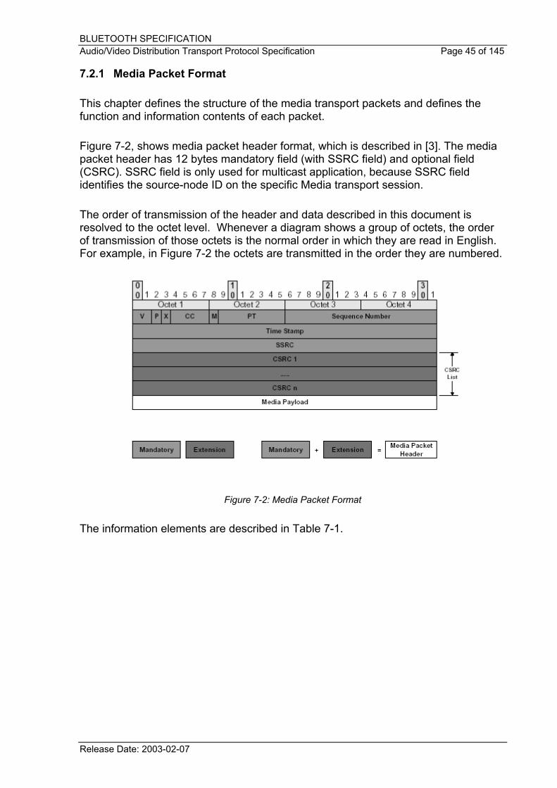
7.2.1 Media Packet Format
This chapter defines the structure of the media transport packets and defines the function and information contents of each packet.
Figure 7-2, shows media packet header format, which is described in [3]. The media packet header has 12 bytes mandatory field (with SSRC field) and optional field (CSRC). SSRC field is only used for multicast application, because SSRC field identifies the source-node ID on the specific Media transport session.
The order of transmission of the header and data described in this document is resolved to the octet level. Whenever a diagram shows a group of octets, the order of transmission of those octets is the normal order in which they are read in English. For example, in Figure 7-2 the octets are transmitted in the order they are numbered.
Figure 7-2: Media Packet Format
The information elements are described in Table 7-1.
Release Date: 2003-02-07
BLUETOOTH SPECIFICATION Audio/Video Distribution Transport Protocol Specification Page 46 of 145
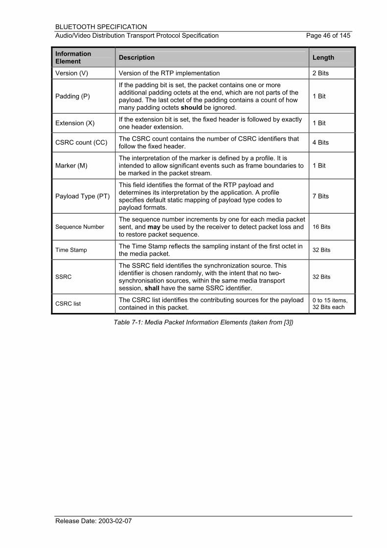
Information Element Description Length
Version (V) Version of the RTP implementation 2 Bits
Padding (P)
If the padding bit is set, the packet contains one or more additional padding octets at the end, which are not parts of the payload. The last octet of the padding contains a count of how many padding octets should be ignored.
1 Bit
Extension (X) If the extension bit is set, the fixed header is followed by exactly one header extension. 1 Bit
CSRC count (CC) The CSRC count contains the number of CSRC identifiers that follow the fixed header. 4 Bits
Marker (M) The interpretation of the marker is defined by a profile. It is intended to allow significant events such as frame boundaries to be marked in the packet stream.
1 Bit
Payload Type (PT)
This field identifies the format of the RTP payload and determines its interpretation by the application. A profile specifies default static mapping of payload type codes to payload formats.
7 Bits
Sequence Number The sequence number increments by one for each media packet sent, and may be used by the receiver to detect packet loss and to restore packet sequence.
16 Bits
Time Stamp The Time Stamp reflects the sampling instant of the first octet in the media packet. 32 Bits
SSRC
The SSRC field identifies the synchronization source. This identifier is chosen randomly, with the intent that no two-synchronisation sources, within the same media transport session, shall have the same SSRC identifier.
32 Bits
CSRC list The CSRC list identifies the contributing sources for the payload contained in this packet.
0 to 15 items, 32 Bits each
Table 7-1: Media Packet Information Elements (taken from [3])
Release Date: 2003-02-07
BLUETOOTH SPECIFICATION Audio/Video Distribution Transport Protocol Specification Page 47 of 145
7.3 Reporting Service
Upper Layer (UL)
Signalling
L2CAP
StreamManager
Upper Layer (UL)
Signalling
StreamManager
Baseband
Device BDevice A
MediaPackets
ReportingPackets
MediaPackets
ReportingPackets
Figure 7-3: Transport Channels for Media Transport and Reporting
Media and Reporting use L2CAP directly. RTP realises transport of the A/V data stream on L2CAP, and RTCP monitors the Quality of Service and conveys necessary information about the participants in the ongoing transport session.
This solution makes use of different transport sessions for reporting and media transport. Each channel carries different packet formats depending on the different type of transport sessions (audio, video, etc.). Different media transport sessions may be opened for the same single video application; each stream corresponds to one of the media streams (object, enhancement layer, etc.). For each opened media transport session, a reporting channel shall be associated. Therefore, a stream session shall include two transport channels, one for Media packets and the other one for Reporting packets.
In AVDTP, only SR, RR and SDES shall be used. They are described in the following sections. For more information, see RFC1889 [3].
7.3.1 Sender Report Reporting packet (SR)
Figure 7-4 shows Sender Report packet. It consists of three sections, possibly followed by a fourth profile-specific extension section if defined. The first section, the header, is eight octets long.
Release Date: 2003-02-07
BLUETOOTH SPECIFICATION Audio/Video Distribution Transport Protocol Specification Page 48 of 145
The information elements are described in Table 7-2.
Release Date: 2003-02-07
BLUETOOTH SPECIFICATION Audio/Video Distribution Transport Protocol Specification Page 49 of 145
Information Element Description Length
Version (V) See Table 7-1
Padding (P) See Table 7-1
Reception Report Count (RC) The number of reception report blocks contained in this packet. 5 Bits
Packet Type (PT) Contains the constant 200 to identify this as an RTCP SR packet. 8 Bits
Length The length of this RTCP packet in 32-bit words minus one, including the header and any padding. 16 Bits
SSRC See Table 7-1
NTP Time Stamp
Indicates the wall clock time when this report was sent so that it may be used in combination with timestamps returned in reception reports from other receivers to measure round-trip propagation to those receivers.
64 Bits
RTP Time Stamp Corresponds to the same time as the NTP timestamp (above), but in the same units and with the same random offset as the RTP timestamps in data packets.
32 Bits
Sender’s Packet Count
The total number of RTP data packets transmitted by the sender since starting transmission up until the time this SR packet was generated.
32 Bits
Sender’s Octet Count
The total number of payload octets( i.e. , not including header or padding) transmitted in RTP data packets by the sender since starting transmission up until the time this SR packet was generated.
32 Bits
SSRC_n (Source Identifier)
The SSRC identifier of the source to which the information in this reception report block pertains. 32 Bits
Fraction Lost
The fraction of RTP data packets from source SSRC_n lost since the previous SR or RR packet was sent, expressed as a fixed-point number with the binary point at the left edge of the field.
8 Bits
Cumulative Number of Packets Lost
The total number of RTP data packets from source SSRC_n that have been lost since the beginning of reception. 24 Bits
Extended Highest Sequence Number Received
The low 16 bits contain the highest sequence number received in an RTP data packet from source SSRC_n, and the most significant 16 bits extend that sequence number with the corresponding count of sequence number cycles.
32 Bits
Inter-arrival Jitter An estimate of the statistical variance of the RTP data packet inter arrival time, measured in timestamp units and expressed as an unsigned integer.
32 Bits
Last SR Timestamp (LSR)
The middle 32 bits out of 64 in the NTP timestamp received as part of the most recent RTCO sender report (SR) packet from source SSRC_n.
32 Bits
Delay since Last SR (DLSR)
The delay, expressed in units of 1/65536 seconds, between receiving the last SR packet from source SSRC_n and sending this reception report block.
32 Bits
Table 7-2: Reporting Packets Information Elements (taken from [3])
Release Date: 2003-02-07
BLUETOOTH SPECIFICATION Audio/Video Distribution Transport Protocol Specification Page 50 of 145
7.3.2 Receiver report packet (RR)
The format of the Receiver Report (RR) packet is the same as that of the SR packet except that the Packet Type (PT) field contains the constant 201 and the five words of sender information are omitted.
7.3.3 Source description packet (SDES)
Each chunk consists of an SSRC or a CSRC identifier followed by a list of zero or more items, which carry information about the SSRC or CSRC.
Source Count (SC) The number of SRC/CSRC chunks contained in this SDES packet. 5 Bits
Packet Type (PT) Contains the constant 202 to identify this as a Reporting SDES packet. 8 Bits
Length See Table 7-2
SSRC_n (Source Identifier) See Table 7-2
Table 7-3: SDES Reporting Packets Information Elements (taken from [3])
There are eight SDES items currently defined by RFC1889 [3]. Figure 7-6 is the CNAME item (the Canonical end-point identifier SDES item) as one example from the SDES items. Because the randomly allocated SSRC identifier may change if a conflict is discovered or if a program is restarted, the CNAME item is required to provide the binding from the SSRC identifier to an identifier for the source that remains constant.
Release Date: 2003-02-07
BLUETOOTH SPECIFICATION Audio/Video Distribution Transport Protocol Specification Page 51 of 145
RTP senders and receivers provide reception quality feedback using report packets, Sender Report packets (SR) or Receiver Report packets (RR).
Let SSRC_r denote the receiver issuing this receiver report. Source SSRC_n can compute the round propagation delay to SSRC_r by recording the time A when his reception report block in the SR or RR is received. It calculates the total round-trip time A - LSR using the last SR timestamp (LSR) field in the report block, and then subtracting the delay since last SR (DLSR) field in the same report block to leave the round-trip propagation delay as (A – LSR – DLSR). This can be used as an approximate measure of distance to cluster receivers, although some links have very asymmetric delays.
7.4 Recovery Service 7.4.1 Scope
ACL links provide a selectable error correction service (FEC 2/3) in the baseband. This protection scheme can correct a single bit error in every 10-bits sequence used to generate the additional parity code. In principle baseband, FEC is always usable for the protection of AV stream data as well.
The baseband FEC is intended to limit the number of retransmissions needed in adverse radio transmissions: in the case that significant burst errors this feature does not help very much since the affected baseband packets are lost. In addition, the baseband FEC service is not selectable for each logical channel separately.
Usually the retransmission of the corrupted baseband packets is required to recover a lost media packet completely.
When retransmission is neither desirable nor applicable, a forward error correction scheme that protects media packets directly in the AV transport layer can be selected as an alternate recovery mechanism. An example of use is in configurations where the sink device operates in a lower power mode than the source device: here the piggybacked acknowledgement of the receiver could fail while the reception of the media packet itself by the same device was actually successful and retransmission is simply squandering.
One additional benefit of the recovery service is to provide the means for applications to differentiate the protection according to the media packet types or contents. For instance, an application can decide to protect either video packets or audio packets
Release Date: 2003-02-07
BLUETOOTH SPECIFICATION Audio/Video Distribution Transport Protocol Specification Page 52 of 145
depending on their respective error-resilience capability or to limit the protection to some vulnerable parts of the stream.
The recovery service shall perform independently of the type of media packet to be protected and the underlying transport features.
Upper Layer (UL)
Signalling
L2CAP
StreamManager
Upper Layer (UL)
Signalling
StreamManager
Baseband
Device BDevice A
Recovery
MediaPackets
ReportingPackets
MediaPackets
RecoveryPackets
Recovery
MediaPackets
MediaPackets
RecoveryPackets
ReportingPackets
Figure 7-7: Transport Channels for Media Transport, Recovery, and Reporting
7.4.2 Overview
The recovery service is based on RFC2733 “An RTP Payload Format for Generic Error Correction” [4]. This document provides a complete specification of the packet format to be adopted for generation and encapsulation of the recovery service packets. It also mandates the procedures to be used for media packet reconstruction at the receiving side.
The recovery service operates independently of the other AVDTP services in a dedicated transport session. Once configured the service is permanently available to handle application requests for media packet protection in the following way:
• At the source side, the service is active on application demand through a specific interface. Recovery packets are generated from the set of media packets to be protected: generation rules are found in [4]. Then the generated recovery packets are automatically filed onto the associated transport channel without additional intervention of the application.
• At the sink side the service is directly triggered by the stream manager entity each time a missing media packet is detected in a protected transport session: the detection of a lost media packet is based on the sequence number control. The recovery service attempts to restore the missing packet using one or several subsequent recovery packets, which have the missing
Release Date: 2003-02-07
BLUETOOTH SPECIFICATION Audio/Video Distribution Transport Protocol Specification Page 53 of 145
media packet in scope. If the original media packet is successfully reconstructed the recovery service calls a stream manager function back to insert the media packet at the stream output interface. If the recovery fails, the missing media packet is signalled to the application and no data is streamed out for the lost packet. No intervention of the application is required during the active recovery phase. A complete specification of the procedure for the reconstruction of missing media packets can be found in [4].
7.4.3 Recovery transport channel
Conformant L2CAP implementations guarantee that subsequent L2CAP packets never share the same baseband payload even when fragmentation is applied: therefore the loss of a single baseband packet only affects a single transported L2CAP packet in the sequence.
To reduce the probability of simultaneous loss of media and recovery packets AVDTP shall encapsulate those packets as payload of individual L2CAP packets. This requirement is actually met when the transport channels are not configured for multiplexing. Implementations that combine multiplexing and recovery services in a source device require additional session and transport management to achieve it.
7.4.4 RTP payload type
The IETF document [4] leaves it up to the referring specification to require the transport of media and recovery packets in common or separate streams.
AVDTP requires that media and recovery packets be transported in separate sessions and/or channels. In the destination device, each payload is identified by its transport session and/or channel ID without the need of a distinct RTP payload type in the packet header.
For compliance with [4] a RTP payload type has to be selected and used for the transmission of the recovery packets between Bluetooth conformant devices: in AVDTP the RTP PT value of each recovery packet shall be set to the one of the source Media stream packet.
All sections of [4] that refer to the Session Description Protocol (SDP) [8] are not applicable for this specification.
7.4.6 Real Time Streaming Protocol (RTSP) requirements
All sections of [4] that refer to the Real Time Streaming Protocol (RTSP) [7] are not applicable for this specification.
Release Date: 2003-02-07
BLUETOOTH SPECIFICATION Audio/Video Distribution Transport Protocol Specification Page 54 of 145
7.4.7 Parity codes
According to [4], the recovery packet payload includes an additional FEC header that provides identification of the protected media packet sequence through a base sequence number and a mask. This identification method extends the coverage window over 24 media packets starting from the indicated base packet.
The combination of a set of media packets used to generate the recovery packet(s) is called a parity code. Any parity code can be used: by means of the base sequence number and the mask information in the recovery packet header the sink device can always reconstruct one or more lost packets depending on the used parity code.
As the parity code information is contained in the recovery packet headers, no signalling or configuration of the channel for a peculiar parity code usage is required. A source device can dynamically adapt the parity code to the channel condition without the use of additional out of band signals. Selection of the best suitable parity codes, depend on the measured traffic conditions and is left to the application.
7.4.8 Recovery Window
Depending on the used parity code, the generation of a single recovery packet is achieved at the source side by picking some media packets up from the sequence and generating a primary parity packet from this covered set.
Depending on the complexity of the coding scheme the reconstruction of any original media packet at the sink side requires some combination of recovery packets and media packets and follows the recovery procedures specified in [4]. As cascaded operations can be required to recover some media packet the length of the packet sequence needed to recover a single media packet loss at the sink side can be larger than the number of original packets used to generate the recovery packet at the source side.
The recovery window size is the number of media packets the sink device can buffer to guarantee the reconstruction of any single packet of the covered sequence.
INT and ACP shall negotiate the maximum recovery window size during the SEP configuration procedure. During streaming the source device can only select coding schemes that are compatible with the configured value.
Limiting the window size tends also to reduce the potential latency and jittering effects when a corrupted packet needs to be recovered.
7.4.9 Recovery SEP capabilities
In order to cope with possible resource limitations of the source and sink devices the following capabilities are exposed and configured in the context of the recovery service:
Release Date: 2003-02-07
BLUETOOTH SPECIFICATION Audio/Video Distribution Transport Protocol Specification Page 55 of 145
• Maximum size of the recovery window, the sink side shall allocate to ensure the reconstruction of any single media packet. The range is 1...24
• Maximum number of media packets that can be used to compute a recovery packet. The range is 1 to 24. A value of 1 means that the service actually operates as an on-demand packet retransmission service.
To serve the sink device correctly with respect to the negotiated recovery window the source device is mandated to schedule each recovery packet transmission immediately after the last original packet used in the parity code generation.
7.4.10 Applicable coding schemes
All coding schemes in [4] that are compatible with the stream end-point capabilities can be used by the source device. Selection of an optimal coding scheme depends on application strategies and device capabilities. Criteria of selection can also vary along the session.
• The lower the number of media packets used to generate a single recovery packet, results in a higher probability of a lost media packet. The reason is that the service fails to reconstruct the original packets, if multiple packet loss occurs in a covered set.
• Applying sporadic coding scheme or changing schemes on the fly can be used to modulate the packet protection in a selective way. This is useful to reduce the total overhead and is more specifically applicable when the source of the media stream uses encoding methods that perform bit classification.
One of the suggested schemes [parity code scheme 2 in [4], sec. 4] makes it possible for encoding and transmitting of recovery packets only. This scheme allows for recovery of single packet losses and some consecutive packet losses with a minimum overhead at the expense of additional processing power. Using such scheme requires that each media packet – corrupted or not - shall be reconstructed from some subsequent recovery packets.
7.4.11 Unsystematic coding schemes
Unsystematic coding schemes are those where the receiver generates parity packets that enable the receiver to reconstruct all the original media packets. No media transport is negotiated and the receiver shall decode the parity packets to derive the media packets. Therefore unsystematic coding schemes are applicable if and only if a recovery session has been successfully configured while the INT did not requested a media session at stream configuration time.
Release Date: 2003-02-07
BLUETOOTH SPECIFICATION Audio/Video Distribution Transport Protocol Specification Page 56 of 145
7.5 Multiplexing Service
The Multiplexing Service, which is conceptually located in the Adaptation Layer of AVDTP (AVDTP-AL), is characterized by a more flexible usage of the underlying transport channels (L2CAP channels) and its packets (L2CAP packets). It is possible to improve the efficiency of the lower layer packet usage. This is achieved by enabling fragmentation, as part of multiplexing, within the Adaptation Layer.
Enabling the Multiplexing Service shall be configured during the Stream Configuration Procedure, see § 6.6. In particular, if an application intends e.g. to have 2 streams, which are established sequentially, to share the same transport channel, the Multiplexing Service shall be configured for both of them from the beginning.
7.5.1 Adaptation Layer PDU packet format
When the multiplexing mode is not configured, an L2CAP payload, which means a PDU of AVDTP, consists of a single media, reporting, or recovery packet, and each transport session of AVDTP uses a different transport (L2CAP) channel. These restrictions are released in the Multiplexing Service. In other terms, an AL-PDU, i.e. a PDU of the AVDTP-AL incorporating Multiplexing Service, may comprise one or multiple packets (media, reporting, or recovery packets), i.e. multiplexed packets may belong to different transport sessions and even different streams. This implies that in Multiplexing Service, an additional header (AL header) is needed, which encapsulates each packet contributing to an AL_PDU. The AL header provides framing of the variable length transport (media/reporting/recovery) packets and ensures a correct mapping to the associated transport session at the sink side.
A B Media PacketC B C Recovery Packet B C Media Packet
AL-PDU
A
B
C
= L2CAP Header
= AL Header
Media/Reporting/Recovery Header
TSID F LCODE
Length (MSB)
Length (LSB)
Figure 7-8: Adaptation Layer Packet Format
The format of the AL-PDU is depicted in Figure 7-8. In this example, two media packets and one recovery packet are contained within the AL-PDU. In general, the sequence of media/reporting/recovery packets in an AL-PDU is arbitrary and dynamic. It is in the responsibility of the source AVDTP-AL entity to serve the different transport sessions and to fill AL-PDU in an appropriate way. In doing so it can e.g. consider expected packet sizes at lower layers, thus help to improve the bandwidth exploitation of the Bluetooth link.
Release Date: 2003-02-07
BLUETOOTH SPECIFICATION Audio/Video Distribution Transport Protocol Specification Page 57 of 145
Nevertheless, some restrictions should be considered. Media and reporting packets involved in the same recovery operation (see § 7.4) should not be packed into the same AL-PDU.
A more instructive example of the Multiplexing Service is given in § 14
7.5.2 Adaptation Layer Header format
The format and contents of the Adaptation Layer header (AL header) is given in Figure 7-8 and Table 7-4.
Information Element Description Length Possible Values
TSID Transport Session Identifier see definition in § 4.13 5 Bits
00000 = Indicates an extension of the AL header: in case of TSID=00000, a second AL header byte, before the length field, is expected and contains the actual TSID, aligned with MSB.
F Adaptation Layer Fragmentation 1 Bit
0 = Un-fragmented transport packet.
1 = Data following represent continuation chunk of transport packet.
LCODE Coding of length field 2 Bits
00 = No length field present
01 = 16 bit length field (in 2 length octets following)
10 = 9 bit length field, MSB = 0, 8 LSBs in 1 octet following
11 = 9 bit length field, MSB = 1, 8 LSBs in 1 octet following
Table 7-4: Adaptation Layer Header Information Elements
In the header the TSID is used to route packets at sink side to the correct transport session, i.e. media, reporting, or recovery part transport session of a certain stream. Note the TSID scope is across sessions for media/reporting/recovery packets of one or multiple streams between a given pair of devices.
The variable length field encoding serves to minimize the overhead while accommodating typical packet lengths (e.g. 9 bits needed to fit DH5 packet length). LCODE=00 (no length field present) can be used to save at least one byte per L2CAP packet. In the last transport packet within an AL-PDU, a length field is not needed because the overall length of the AL-PDU is indicated in the L2CAP header.
Release Date: 2003-02-07
BLUETOOTH SPECIFICATION Audio/Video Distribution Transport Protocol Specification Page 58 of 145
Consequently, the AL header spans a minimum of one byte, a typical length of 2 bytes (one length byte present) and, without extension mechanism, a maximum of 3 bytes.
7.5.3 Adaptation Layer Fragmentation
The source side AVDTP-AL may choose to use slot capacity more efficiently, by starting a transport packet in the end of an L2CAP payload (end of AL-PDU) and continuing it in a following AL-PDU. This mechanism is called Adaptation Layer Fragmentation.
• The starting segment shall be the last transport packet within an AL-PDU, with the length field indicating the original length of the un-fragmented transport packet. Though F=0 for the starting segment, the sink side AVDTP-AL recognizes the fragmentation by the length exceeding the AL-PDU packet boundary, and expects the transport packet to be continued in the next AL-PDU segment belonging to the same transport session.
• The continuation segment of a fragmented transport packet is marked by F=1. Its length field indicates the actual segment length. Exception: this segment ranges in the end of the AL-PDU again and is meant to continue in yet another AL-PDU; in this case, the length field contains the length of all remaining segments of the fragmented transport packet.
• Both the SRC and the SNK shall be aware that there are rare constellations where a loss of fragments cannot be detected immediately.
7.6 Robust Header Compression Service
This service is based on ROHC, robust header compression, which can be found in the IETF RFC [5]. The IETF standard includes compression of IP, UDP, and the RTP header. Within the AVDTP protocol, only the RTP compression part is used.
The following sections describe the modifications of IETF RFC [5] (ROHC) that are required when used in conjunction within AVDTP. The changes are required because no IP or UDP headers are contained in packets transported with AVDTP.
7.6.1 CRC Calculation
In all packets, the CRC is calculated using only the static and dynamic fields of the uncompressed RTP header.
7.6.2 Per-Channel Parameters
As the multiplexing of transport sessions, in Multiplexing Mode only, is achieved by a separate AVDTP mechanism (see § 7.5), context ID numbers are not needed in
Release Date: 2003-02-07
BLUETOOTH SPECIFICATION Audio/Video Distribution Transport Protocol Specification Page 59 of 145
AVDTP. Therefore, LARGE_CIDS= false is set. This setting covers the option to use no prefix byte at all; i.e., implicit CID=0.
7.6.3 Feedback Channel
For the ROHC feedback in AVDTP, the following choices exist:
• No back-channel is used at all (the sink device chooses not to request transition from U-mode to O/R-mode, e.g. if it prefers to use the slots for other traffic, or it is a multicast configuration).
• The reverse direction (upstream) of the same transport session is used for ROHC feedback. The same mapping of transport session and transport channel is valid as for the downstream transfer.
7.6.4 Packet Types
Packet Type Description
IP-ID Packets The UOR-1-ID, UOR-1-TS, UOR-2-ID, and UOR-2-TS packet types are not valid in AVDTP since there cannot be any IP-ID to transmit.
Extension Format 3 in UOR-2 Packets
In the header, the options “I” and “ip” shall have the value 0. As the RTP mixer functionality is not used in AVDTP, compression of CSRC lists is not necessary, such that the “CSRC” option takes the value 0.
Release Date: 2003-02-07
BLUETOOTH SPECIFICATION Audio/Video Distribution Transport Protocol Specification Page 60 of 145
8 Signalling Messages
8.1 Stream Configuration Procedure Service Capabilities of each SEP can be discovered using signalling commands such as AVDTP_DISCOVER_CMD and AVDTP_GET_CAPABILITIES_CMD. Service Capabilities are selected using AVDTP_SET_CONFIGURATION_CMD. The selected Service Capabilities are valid for the SEID. To retrieve the Service Capabilities of the SEP AVDTP_GET_CONFIGURATION_CMD is used. Procedure to make a SEP connection is as follows.
Step 1. Discover stream end-points within an ACP, using AVDTP_DISCOVER_CMD
Step 2. Select Stream End Point
Step 3. Collect Service Capabilities of the target SEID using AVDTP_GET_CAPABILITIES_CMD
Step 4. Select the Capabilities on the target device for the SEP using AVDTP_SET_CONFIGURATION_CMD.
Initiator AcceptorAVDTP AVDTP
AVDTP_DISCOVER_CMD
AVDTP_DISCOVER_RSP
AVDTP_GET_CAPABILITIES_CMD
AVDTP_GET_CAPABILITIES_RSP
AVDTP_SET_CONFIGURATION_CMD
AVDTP_SET_CONFIGURATION_RSP
Figure 8-1: Example of the Service Capabilities negotiation procedures
8.2 Signalling Message format
This section defines the structure of the signalling messages used to gather information on stream capabilities and media stream establishment.
Release Date: 2003-02-07
BLUETOOTH SPECIFICATION Audio/Video Distribution Transport Protocol Specification Page 61 of 145
Signalling message
Signalling messageSignallingHeader
Signalling messageSignallingHeader
L2CAPHeader
AVDTP Signalling
L2CAP Layer
Figure 8-2: Packet format for signalling message (Single L2CAP packet)
Figure 8-2 show a signalling message process as it passes down the layers. A signal request arrives at AVDTP from the Upper Layer. AVDTP formats the request and adds AVDTP signalling header. The AVDTP signalling message is then passed to L2CAP for transportation to the peer. Only one AVDTP signalling message is allowed in one L2CAP packet.
8.3 Signal Fragmentation
Among others fragmentation and reassembly of signalling messages can be needed to cope with the MTU requirements of the receiving unit.
Figure 8-3, shows how a large signal is fragmented as it travels through the layers. A request is sent from the Upper Layer to send a signal to the peer AVDTP signalling entity. When AVDTP receives the request, the request is formatted accordingly, ready for transmission to the peer AVDTP entity. AVDTP then splits the signal into suitable size packets, ready for transmission.
Signalling Request
Signalling Message
AVDTP Layer
A B C
AD BD CDL2CAP Layer
A = Start PacketHeader
D = L2CAP Header
B = Continue PacketHeader
C = End PacketHeader
Figure 8-3: Packet format for signalling message (Multi L2CAP packets)
Release Date: 2003-02-07
BLUETOOTH SPECIFICATION Audio/Video Distribution Transport Protocol Specification Page 62 of 145
The first packet is a Start Packet and is formatted as in Figure 8-5. The packets that follow the Start Packet are termed as Continue Packets and are formatted as in Figure 8-6, when the last packet of the signal is reached it is formatted as in Figure 8-6. Each packet type is sent in a single L2CAP packet.
The sender is mandated to transmit sequentially all packets belonging to same message before handling the packets from the next message; in other words interleaving of packets from different messages on the air is not allowed.
Note that it is permitted to breakdown a packet sequence (command or response message) to send an Abort command message in the same direction. The remaining packets consecutive to an aborted message shall be flushed by the sender.
8.4 Signal command and response headers
Shown below are the formats of the general signalling command and response signals. To enable the use of large size signals two header formats are used. One format provides information elements to identify the start of a fragmented signal and the length of the signal. The other provides information elements suitable for continue, end and single packets.
7 6 5 4 3 2 1 0 Octet
Transaction Label Packet Type Message Type 0
RFA Signal Identifier 1
Figure 8-4: Signalling message format for single packets
7 6 5 4 3 2 1 0 Octet
Transaction Label Packet Type Message Type 0
NOSP = Number Of Signal Packets see § 8.18.4 1
RFA Signal Identifier 2
Figure 8-5: Signalling message format for start packets
7 6 5 4 3 2 1 0 Octet
Transaction Label Packet Type Message Type 0
Figure 8-6: Signalling message format for continue and end packets
8.4.1 Transaction Label
The Transaction Label specifies a unique tag for each outstanding transaction from INT. The transaction label field is four bits in length. On the ACP side, the transaction label received in a signalling command frame shall be used as the transaction label returned in the corresponding signalling response frame.
Release Date: 2003-02-07
BLUETOOTH SPECIFICATION Audio/Video Distribution Transport Protocol Specification Page 63 of 145
8.4.2 Packet Type
Signalling messages shall be fragmented by the sender when they are oversized regarding the MTU requirement of the channel. The sender may also decide to fragment a message to save resources on its part. This field indicates that signalling message consists of single packet or multi packets. In the multi packets case, this field also indicates the Packet Type of the signalling message (start packet, continue packet or end packet).
2 Bits
3 2
0 0 Single Packet
0 1 Start Packet
1 0 Continue Packet
1 1 End Packet
Table 8-1: Packet Type field values
8.4.3 Message Type
On each command packet, the Message Type field specifies the command type of the signalling command. On each signalling response packet, the Message Type field specifies the result of corresponding signalling command on ACP.
2 Bits
1 0
0 0 Command
0 1 RFD
1 0 Response Accept
1 1 Response Reject
Table 8-2: Message Type field values
8.4.4 Signal Identifier
The Signal Identifier field indicates the signalling command from INT to ACP. On the ACP side, the Signal Identifier field value received in a signalling command message shall be used as the Signal Identifier field value in the corresponding signalling response message.
8.4.5 Packet size requirements
The receiver of a fragmented message may allocate the resources for message reassembly based on the start packet length and the number of packets information elements provided by the first packet. For this reason:
Release Date: 2003-02-07
BLUETOOTH SPECIFICATION Audio/Video Distribution Transport Protocol Specification Page 64 of 145
1. The L2CAP payload of the start and all continue packets of a fragmented message shall have the same length
2. The L2CAP payload of end packets shall not be larger than the start and any possible continue packet that belong to the same message.
8.4.6 Message integrity verification at receiver side
The receiver of an AVDTP signalling message shall not interpret or pass corrupted messages to the upper layer. Those messages are discarded and not signalled to the local upper layer; no signalling message is returned to the sender. Possible corrupted messages are:
• Response messages where the transaction label cannot match a previous command sent to the remote device
• All incoming messages with the message type set to RFD
• Messages with an unexpected packet type in the sequence (e.g. a first packet having a packet type field set to ‘continue’ or ‘end’)
• Incomplete fragmented messages (the number of received packet does not match the value of the NOSP field in the start packet)
Release Date: 2003-02-07
BLUETOOTH SPECIFICATION Audio/Video Distribution Transport Protocol Specification Page 65 of 145
8.5 Signalling command set
In this section, signalling command and responses are defined. The signalling message format is shown in § 8.2.
The detail encoding of signal command and response information elements are described in following sections. Table 8-3 defines the signal identifier field value (see § 8.17 for definition of field) for each signalling message. The signal format and information elements are specified in the following sections.
8.6 Stream End Point Discovery 8.6.1 Stream End Point Discovery Command
The AVDTP_DISCOVER_CMD is sent from INT to ACP and it requests to get the overview of all SEP information of the ACP.
7 6 5 4 3 2 1 0 Octet
Signalling Header see 8.4 0
RFA AVDTP_DISCOVER 1
Figure 8-7: Stream End Point Discovery command message
8.6.2 Stream End Point Discovery Response
AVDTP_DISCOVER_RSP message is sent from ACP to INT as a response to AVDTP_DISCOVER_CMD. The response contains an overview of all stream end-points that the ACP supports. Note this information is only valid for one stream establishment procedure, as the streaming resources within the ACP are dynamic
Release Date: 2003-02-07
BLUETOOTH SPECIFICATION Audio/Video Distribution Transport Protocol Specification Page 66 of 145
and could be used by other devices. The Media Type value returned for each SEP, is defined in the Bluetooth Assigned Numbers document, see [6].
7 6 5 4 3 2 1 0 Octet
Signalling Header see 8.4 0
RFA AVDTP_DISCOVER 1
First ACP SEID In Use RFA 2
Media Type TSEP RFA 3
[Other ACP SEID Information (2 octets each)] :
Figure 8-8: Stream End Point Discovery Response message format
8.6.3 Stream End Point Discovery Reject
7 6 5 4 3 2 1 0 Octet
Signalling Header see 8.4 0
RFA AVDTP_DISCOVER 1
ERROR_CODE see § 8.18.6 2
Figure 8-9: Stream End Point Discovery Reject message format
8.7 Get Capabilities 8.7.1 Get Capabilities Command
AVDTP_GET_CAPABILITIES_CMD is sent from INT to ACP, and it is used to get specific information for a SEP of an ACP. The SEID field value specifies the target SEP within ACP.
7 6 5 4 3 2 1 0 Octet
Signalling Header see 8.4 0
RFA AVDTP_GET_CAPABILITIES 1
ACP SEID RFA 2
Figure 8-10: Get Capabilities Command message format
8.7.2 Get Capabilities Response
AVDTP_GET_CAPABILITIES_RSP message is sent from ACP to INT, and indicates the SEP capabilities requested by the corresponding AVDTP_GET_CAPABILITIES_CMD message from INT.
Release Date: 2003-02-07
BLUETOOTH SPECIFICATION Audio/Video Distribution Transport Protocol Specification Page 67 of 145
7 6 5 4 3 2 1 0 Octet
Signalling Header see 8.4 0
RFA AVDTP_GET_CAPABILITIES 1
Service Capabilities see § 8.19 :
Figure 8-11: Get Capabilities Response message format
8.7.3 Get Capabilities Reject
After receiving an AVDTP_GET_CAPABILITIES_CMD from INT, the ACP tries to gather the Stream end-point capabilities. If the command fails, an AVDTP_GET_CAPABILITIES_REJ is sent back to the INT. The packet contains an error code as to why the command was rejected.
7 6 5 4 3 2 1 0 Octet
Signalling Header see 8.4 0
RFA AVDTP_GET_CAPABILITIES 1
ERROR_CODE see § 8.18.6 2
Figure 8-12: Stream Get Capabilities Reject message format
8.8 Stream Configuration 8.8.1 Set Configuration Command
After receiving the AVDTP_GET_CAPABILITIES_RSP, INT selects the required SEP and its Service Capabilities for sending/receiving A/V stream to/from ACP. The INT notifies the selected SEP and its Service Capabilities to ACP by using AVDTP_SET_CONFIGURATION_CMD. AVDTP_SET_CONFIGURATION_CMD indicates all of required Service Capabilities for the SEP. The details of the Service Capabilities are defined in § 8.19.
7 6 5 4 3 2 1 0 Octet
Signalling Header see 8.4 0
RFA AVDTP_SET_CONFIGURATION 1
ACP SEID RFA 2
INT SEID RFA 3
Service Capabilities see § 8.19 also see Note 1 :
Figure 8-13: Set Configuration Command message format
Note 1. Any Service Capabilities Types can be present within this signal
Release Date: 2003-02-07
BLUETOOTH SPECIFICATION Audio/Video Distribution Transport Protocol Specification Page 68 of 145
8.8.2 Set Configuration Response
After receiving an AVDTP_SET_CONFIGURATION_CMD from INT, AVDTP_SET_CONFIGURATION_RSP packet is sent from ACP to INT.
7 6 5 4 3 2 1 0 Octet
Signalling Header see 8.4 0
RFA AVDTP_SET_CONFIGURATION 1
Figure 8-14: Set Configuration Response message format
8.8.3 Set Configuration Reject
After receiving an AVDTP_SET_CONFIGURATION_CMD from INT, the ACP tries to configure the Stream end-point. If the configuration fails, an AVDTP_SET_CONFIGURATION_REJ is sent from ACP to INT. The packet contains a reject reason and details on why the command was rejected.
7 6 5 4 3 2 1 0 Octet
Signalling Header see 8.4 0
RFA AVDTP_SET_CONFIGURATION 1
Service Category see Table 8-4 and Note 2 2
ERROR_CODE see § 8.18.6 3
Figure 8-15: Set Configuration Reject message format
Note 2. Contains the value of the first Service Category to fail.
8.9 Get Stream configuration 8.9.1 Get Configuration Command
AVDTP_GET_CONFIGURATION_CMD is used to interrogate the current configuration of a stream end-point.
7 6 5 4 3 2 1 0 Octet
Signalling Header see 8.4 0
RFA AVDTP_GET_CONFIGURATION 1
ACP SEID RFA 2
Figure 8-16: Get Configuration Command message format
8.9.2 Get Configuration Response
When an ACP receives, an AVDTP_GET_CONFIGURATION_CMD AVDTP_GET_CONFIGURATION_RSP is sent back to the INT. The response contains the current configuration of the requested stream end-point.
Release Date: 2003-02-07
BLUETOOTH SPECIFICATION Audio/Video Distribution Transport Protocol Specification Page 69 of 145
7 6 5 4 3 2 1 0 Octet
Signalling Header see 8.4 0
RFA AVDTP_GET_CONFIGURATION 1
Service Capabilities see § 8.19 also see Note 1 :
Figure 8-17: Get Configuration Response message format
Note 1. All Service Capabilities Types can be present within this signal
8.9.3 Get Configuration Reject
When an ACP receives, an AVDTP_GET_CONFIGURATION_CMD and there has been an error in processing the request then an AVDTP_GET_CONFIGURATION_REJ is sent back to the INT. The response contains a reject reason as to why the command was rejected.
7 6 5 4 3 2 1 0 Octet
Signalling Header see 8.4 0
RFA AVDTP_GET_CONFIGURATION 1
ERROR_CODE see § 8.18.6 2
Figure 8-18: Get Configuration Reject message format
Devices participating within a stream can change Application Service Capabilities. If a device wants to reconfigure Application Service Capabilities, an AVDTP_RECONFIGURE_CMD is used. The device that issues the command becomes the INT.
7 6 5 4 3 2 1 0 Octet
Signalling Header see 8.4 0
RFA AVDTP_RECONFIGURE 1
ACP SEID RFA 2
Service Capabilities see § 8.19 also see Note 2 :
Figure 8-19: Reconfigure Command message format
Note 2. Only Media Codec Capabilities see § 8.19.5 and Content Protection Capabilities see § 8.19.6 can be present within this signal.
Release Date: 2003-02-07
BLUETOOTH SPECIFICATION Audio/Video Distribution Transport Protocol Specification Page 70 of 145
8.10.2 Reconfigure Response
When the ACP receives an AVDTP_RECONFIGURE_CMD the stream is reconfigured with the provided configuration parameters. Upon a successful reconfiguration of the stream, an AVDTP_RECONFIGURE_RSP is sent back to the INT.
A Reconfigure command has a limited scope: only the Application Service Capabilities can be addressed for reconfiguration once the stream is open. For instance if the reconfigure command addresses the Media Transport Capabilities the ACP shall return a reject message with an ‘INVALID_CAPABILITIES’ ERROR_CODE.
7 6 5 4 3 2 1 0 Octet
Signalling Header see 8.4 0
RFA AVDTP_RECONFIGURE 1
Figure 8-20: Reconfigure Response message format
8.10.3 Reconfigure Reject
If the ACP cannot reconfigure the stream, then an AVDTP_RECONFIGURE_REJ is sent back to the INT. The reject signal contains an error code as to why the request was rejected.
7 6 5 4 3 2 1 0 Octet
Signalling Header see 8.4 0
RFA AVDTP_RECONFIGURE 1
Service Category see Table 8-4 and Note 3 2
ERROR_CODE see § 8.18.6 3
Figure 8-21: Reconfigure Reject message format
Note 3. Contains the value of the first Service Category to fail.
Release Date: 2003-02-07
BLUETOOTH SPECIFICATION Audio/Video Distribution Transport Protocol Specification Page 71 of 145
8.11 Stream Establishment
The following sections define signals used to establish and close stream end-points. Information elements within the signals are defined in § 8.17
8.11.1 Open Stream Command
AVDTP_OPEN_CMD is used to the establish transport channels for a configured SEP. The INT opens the stream, and if necessary, the associated Transport Channels. In case Multiplexing Mode is required explicit Transport Session Identifiers shall be supplied with the associated Transport Channel Identifiers during the AVDTP_SET_CONFIGURATION_CMD message see § 8.8
7 6 5 4 3 2 1 0 Octet
Signalling Header see 8.4 0
RFA AVDTP_OPEN 1
ACP SEID RFA 2
Figure 8-22: Open Stream Command message format
8.11.2 Open Stream Response
After receiving the AVDTP_OPEN_CMD from INT, AVDTP_OPEN_RSP is sent from ACP to INT. This response signals to the INT that the stream is open.
7 6 5 4 3 2 1 0 Octet
Signalling Header see 8.4 0
RFA AVDTP_OPEN 1
Figure 8-23: Open Stream Response message format
Upon reception of AVDTP_OPEN_RSP, the INT sets up the lower transport (L2CAP) channels as required by the configured service. If Multiplexing Service is not configured, individual transport channels for each transport session are established as specified in [1]. If Multiplexing Service is configured, new transport channels are only established if necessary, in accordance with the configuration settings.
Release Date: 2003-02-07
BLUETOOTH SPECIFICATION Audio/Video Distribution Transport Protocol Specification Page 72 of 145
8.11.3 Open Stream Reject
After receiving AVDTP_OPEN_CMD from INT, the ACP verifies if a stream connection can be established according to the configured service for the stream connection (e.g. in case of Multiplexing Service, if the mapping of TSIDs and TCIDs is possible. This reject contains an error code as to why the command was rejected).
7 6 5 4 3 2 1 0 Octet
Signalling Header see 8.4 0
RFA AVDTP_OPEN 1
ERROR_CODE see § 8.18.6 2
Figure 8-24: Open Stream Reject message format
8.12 Stream Start 8.12.1 Start Stream Command
After receiving AVDTP_START_CMD from INT, the ACP puts the stream into streaming, ready to accept streaming media.
7 6 5 4 3 2 1 0 Octet
Signalling Header see 8.4 0
RFA AVDTP_START 1
First ACP SEID RFA 2
[Other ACP SEIDs] RFA :
Figure 8-25: Start Stream Command message format
8.12.2 Start Stream Response
After receiving AVDTP_START_CMD from INT, the ACP puts the stream(s) into streaming mode, ready to accept streaming media. AVDTP_START_RSP is sent back to the INT. This response contains an acknowledgement that the stream(s) have been started.
7 6 5 4 3 2 1 0 Octet
Signalling Header see 8.4 0
RFA AVDTP_START 1
Figure 8-26: Start Stream Response message format
Release Date: 2003-02-07
BLUETOOTH SPECIFICATION Audio/Video Distribution Transport Protocol Specification Page 73 of 145
8.12.3 Start Stream Reject
After receiving AVDTP_START_CMD from INT, the ACP attempts to put the stream(s) into streaming mode, ready to accept streaming media. If any of the streams fail to start then an AVDTP_START_REJ is sent back to the INT. This reject contains an error code as to why the command has been rejected.
7 6 5 4 3 2 1 0 Octet
Signalling Header see 8.4 0
RFA AVDTP_START 1
ACP SEID see Note 4 RFA 2
ERROR_CODE see § 8.18.6 3
Figure 8-27: Start Stream Reject message format
Note 4. Contains the value of the first SEP’s SEID that failed. The ACP shall process the SEPs in the order they are listed in the Start Stream Command and stop processing when the first error occurs.
8.13 Stream Release 8.13.1 Close Stream Command
AVDTP_CLOSE_CMD requests can be sent by any device participating within a stream. The device that initiates the stream closure takes the role of INT. When the INT issues AVDTP_CLOSE_CMD the ACP, after receiving the command, shall act on the AVDTP_CLOSE_CMD and close its own references to the stream end-point.
7 6 5 4 3 2 1 0 Octet
Signalling Header see 8.4 0
RFA AVDTP_CLOSE 1
ACP SEID RFA 2
Figure 8-28: Close Stream Command message format
8.13.2 Close Stream Response
After receiving AVDTP_CLOSE_CMD from INT, AVDTP_CLOSE_RSP is sent from ACP to INT. This response contains an acknowledgement that the stream is closed within the ACP.
7 6 5 4 3 2 1 0 Octet
Signalling Header see 8.4 0
RFA AVDTP_CLOSE 1
Figure 8-29: Close Stream Response message format
Release Date: 2003-02-07
BLUETOOTH SPECIFICATION Audio/Video Distribution Transport Protocol Specification Page 74 of 145
8.13.3 Close Stream Reject
If an AVDTP_CLOSE_CMD is sent by INT and the stream cannot be closed then an AVDTP_CLOSE_REJ is sent back to the INT indicating why the stream could not be closed.
7 6 5 4 3 2 1 0 Octet
Signalling Header see 8.4 0
RFA AVDTP_CLOSE 1
ERROR_CODE see § 8.18.6 2
Figure 8-30: Close Stream Reject message format
8.14 Stream Suspend 8.14.1 Suspend Command
After receiving AVDTP_SUSPEND_CMD from INT, the ACP suspends the required stream(s).
7 6 5 4 3 2 1 0 Octet
Signalling Header see 8.4 0
RFA AVDTP_SUSPEND 1
First ACP SEID RFA 2
[Other ACP SEIDs] RFA :
Figure 8-31: Suspend Command message format
8.14.2 Suspend Response
After receiving AVDTP_SUSPEND_CMD from INT, the ACP suspends streaming on the indicated streaming end-point(s). AVDTP_SUSPEND_RSP is sent back to the INT. This response is the acknowledgement that the stream(s) have been suspended.
7 6 5 4 3 2 1 0 Octet
Signalling Header see 8.4 0
RFA AVDTP_SUSPEND 1
Figure 8-32: Suspend Response message format
Release Date: 2003-02-07
BLUETOOTH SPECIFICATION Audio/Video Distribution Transport Protocol Specification Page 75 of 145
8.14.3 Suspend Reject
After receiving AVDTP_SUSPEND_CMD from INT, the ACP attempts to suspend the stream(s), identified by the SEID(s). If any of the stream(s) fail to suspend, an AVDTP_SUSPEND_REJ is sent back to the INT. The reject contains the first SEID that could not be suspended and an accompanying error code, as to why the stream could not be suspended.
7 6 5 4 3 2 1 0 Octet
Signalling Header see 8.4 0
RFA AVDTP_SUSPEND 1
ACP SEID see Note 5 RFA 2
ERROR_CODE see § 8.18.6 3
Figure 8-33: Suspend Reject message format
Note 5. Indicates the first SEID that failed to be suspended.
8.15 Abort 8.15.1 Abort Command
During stream establishment, if either the device no longer wants to proceed, AVDTP_ABORT_CMD is used. The command signals that stream establishment be aborted. AVDTP_ABORT_CMD can be used in any state.
7 6 5 4 3 2 1 0 Octet
Signalling Header see 8.4 0
RFA AVDTP_ABORT 1
ACP SEID RFA 2
Figure 8-34: Abort Command message format
8.15.2 Abort Response
AVDTP_ABORT_RSP is sent on acknowledgment of an AVDTP_ABORT_CMD in case it contains a valid SEID. If an AVDTP_ABORT_CMD contains an invalid SEID, no response shall be sent.
7 6 5 4 3 2 1 0 Octet
Signalling Header see 8.4 0
RFA AVDTP_ABORT 1
Figure 8-35: Abort Response message format
Release Date: 2003-02-07
BLUETOOTH SPECIFICATION Audio/Video Distribution Transport Protocol Specification Page 76 of 145
8.16 Security Control 8.16.1 Security Control Command
The Security Control Command is sent from the INT to ACP and is used to send content protection commands to ACP. The SEID field value specifies the target SEP in ACP.
7 6 5 4 3 2 1 0 Octet
Signalling Header see 8.4 0
RFA AVDTP_SECURITY_CONTROL 1
ACP SEID RFA 2
Content Protection Method Dependent Data :
Figure 8-37: Security Control command message format
8.16.2 Security Control Response
Security Control Response is sent from ACP to INT in acknowledgement to a Security Control Command; it is also used for sending content protection control response to INT. The SEID field value specifies the target SEP in ACP.
7 6 5 4 3 2 1 0 Octet
Signalling Header see 8.4 0
RFA AVDTP_SECURITY_CONTROL 1
Content Protection Method Dependent Data :
Figure 8-38: Security Control response message format
8.16.3 Security Control Reject
7 6 5 4 3 2 1 0 Octet
Signalling Header see 8.4 0
RFA AVDTP_SECURITY_CONTROL 1
ERROR_CODE see § 8.18.6 2
Figure 8-39: Security Control Reject message format
8.17 General Reject
General Reject message is used by an ACP to respond a command message that contains an invalid Signal Identifier.
Release Date: 2003-02-07
BLUETOOTH SPECIFICATION Audio/Video Distribution Transport Protocol Specification Page 77 of 145
7 6 5 4 3 2 1 0 Octet
Transaction Label RFA 0 Packet Type
RFA 1
Figure 8-40: General Reject response format
8.18 Information Elements
The following sections define all the information elements used in the signalling messages.
8.18.1 Stream End-point IDentifier (SEID, INT SEID, ACP SEID)
Description This information element identifies a unique identifier for the SEP. In the course of stream session a local SEID at each side of the SEP connection. See definition in 4.10
A SEID is always assigned in the local space of the device. A device that initiates a signalling procedure to address a peculiar Stream End Point shall always use the remote device SEID assignment.
In the course of the Discovery procedure only the ACP device exposes its own SEID assignments to the INT device. When the roles change the original ACP wants in turn to initiate a signalling procedure to address the configured SEP for instance e.g. to start or suspend the stream. To achieve it the original ACP device shall be aware of the SEID the original INT device has locally assigned to the addressed Stream End Point. This information shall be transmitted by the original INT device as an additional information element of the AVDTP_SET_CONFIGURATION_CMD message. Afterwards each end is able to address the Stream End Point using the remote device SEID.
In all signalling procedures INT SEID and ACP SEID refer to the SEID the device that plays the INT resp. ACP role in the context of this procedure has assigned.
Release Date: 2003-02-07
BLUETOOTH SPECIFICATION Audio/Video Distribution Transport Protocol Specification Page 78 of 145
8.18.2 Length Of Service Capability (LOSC)
Description A total length of the individual service capability. The LOSC field provides only the length of the service capability following this LOSC information element.
Length: 8 Bits
Possible Values 0x00 to 0xFF (In Octets)
8.18.3 Stream End-point Type, Source or Sink (TSEP)
Description This field indicates if the stream end-point is SNK or SRC. The bit assignment of the TSEP field is shown below.
Length 1 Bit
Possible Values 0 = Stream End Point (SEP) is of type SRC
1 = Stream End Point (SEP) is of type SNK
8.18.4 Number Of Signal Packets (NOSP)
Description This information element indicates how many packets are present in a fragmented signalling packet.
Length: 8 Bits
Possible Values 0x01 to 0xFF
8.18.5 Stream End Point In Use (In Use)
Description This information element indicates if a stream end-point is currently In Use or not.
Length: 1 Bit
Possible Values 0 = SEP is Not In Use 1 = SEP is In Use
8.18.6 Signalling Errors (ERROR_CODE)
AVDTP defines an 8-bits ERROR_CODE field transported over the air in signalling response messages when an ACP device rejects a signalling command message received from a distant INT device. The ERROR_CODE field received from an ACP device is exposed to the INT application through the AVDTP service interface.
According to this definition the ERROR_CODE information can only be reported in AVDT_*_Cfm events generated at the INT/AVDTP interface after receipt of a response message from the addressed ACP device in the correlated transaction.
Release Date: 2003-02-07
BLUETOOTH SPECIFICATION Audio/Video Distribution Transport Protocol Specification Page 79 of 145
This ERROR_CODE information is transported as a cross-device information and can have different causes:
• ACP Application reject: the ACP application rejects a request it received from the remote INT side through a *_Ind event. For instance an ACP application can decide to reject the INT request due to insufficient resources or the request contains invalid application data (e.g. SEP identifier out of range).
• An ACP/AVDTP entity is not able to generate a valid *_Ind event to inform its local application of the reception of a command signal. For instance, the received signal identifier in the message is out of range.
Other error conditions reported to the application are local to the service call and therefore are out of the scope of the ERROR_CODE definition.
8.18.6.1 ERROR_CODE usage
- ACP application rejects an INT command signal
The application has received a valid request (AVDT_*_Ind) from a remote device however the INT rejects the command. The reason for reject is indicated by the ERROR_CODE value. ACP/AVDTP encapsulates this ERROR_CODE value in a signalling reject message. On receipt of the reject message INT/AVDTP reports the ERROR_CODE value to the local application through the AVDT_*_Cfm event callback.
App(INT)
AVDTP(INT)
App(ACP)
AVDTP(ACP)
AVDT_*_Rsp (...,ERROR_CODE,Result = OK)
AVDT_*_Req (...,Result = OK)
Signalling response (... ERROR_CODE)
AVDT_*_Cfm (...,ERROR_CODE)
AVDT_*_Ind(... )
Signalling command (...)
Figure 8-41: ACP Application rejects an INT command
Release Date: 2003-02-07
BLUETOOTH SPECIFICATION Audio/Video Distribution Transport Protocol Specification Page 80 of 145
- ACP/AVDTP rejects an INT command signal
A received command signal cannot be interpreted by ACP/AVDTP entity (e.g. contains invalid format information like an out-of –range signal identifier). ACP/ AVDTP does not generate an AVDT_*_Ind event to inform its local application but generates a reject response to the INT device. The ERROR_CODE field contains the reason of rejection.
App(INT)
AVDTP(INT)
App(ACP)
AVDTP(ACP)
AVDT_*_Req (...,Result = OK)
Signalling response (... ERROR_CODE)
AVDT_*_Cfm (...,ERROR_CODE)
Signalling command(... )
Figure 8-42: ACP/AVDTP rejects an INT command
Release Date: 2003-02-07
BLUETOOTH SPECIFICATION Audio/Video Distribution Transport Protocol Specification Page 81 of 145
8.18.6.2 ERROR_CODE tables
ACP to INT, Signal Response Header Error Codes
Error ID
Related Signalling command
Error Abbreviation Error Description
0x01 All messages BAD_HEADER_FORMAT The request packet header format error that is not specified above ERROR_CODE
ACP to INT, Signal Response Payload Format Error Codes
Error ID
Related Signalling command
Error Abbreviation Error Description
0x11
All messages BAD_LENGTH The request packet length is not match the assumed length.
0x12 All messages BAD_ACP_SEID The requested command indicates an invalid ACP SEID (not addressable)
0x13 Set Configuration SEP_IN_USE The SEP is in use 0x14 Reconfigure SEP_NOT_IN_USE The SEP is not in use 0x17 Set Configuration
Reconfigure BAD_SERV_CATEGORY The value of Service
Category in the request packet is not defined in AVDTP.
0x18 All messages BAD_PAYLOAD_FORMAT The requested command has an incorrect payload format (Format errors not specified in this ERROR_CODE)
0x19 All messages NOT_SUPPORTED_COMMAND The requested command is not supported by the device
0x1A Reconfigure INVALID_CAPABILITIES The reconfigure command is an attempt to reconfigure a transport service capabilities of the SEP. Reconfigure is only permitted for application service capabilities
ACP to INT, Signal Response Transport Service Capabilities Error Codes
Error ID
Related Signalling command
Error Abbreviation Error Description
0x22 Set Configuration
BAD_RECOVERY_TYPE The requested Recovery Type is not defined in AVDTP.
0x23 Set Configuration
BAD_MEDIA_TRANSPORT_FORMAT The format of Media Transport Capability is not correct.
0x25 Set Configuration
BAD_RECOVERY_FORMAT The format of Recovery Service Capability is not correct.
0x26 Set Configuration
BAD_ROHC_FORMAT The format of Header Compression Service
Release Date: 2003-02-07
BLUETOOTH SPECIFICATION Audio/Video Distribution Transport Protocol Specification Page 82 of 145
Capability is not correct. 0x27 Set Configuration
BAD_CP_FORMAT The format of Content
Protection Service Capability is not correct.
0x28 Set Configuration
BAD_MULTIPLEXING_FORMAT The format of Multiplexing Service Capability is not correct.
0x29 Set Configuration
UNSUPPORTED_CONFIGURAION Configuration not supported.
ACP to INT, Procedure Error Codes
Error ID
Related Signalling command
Error Abbreviation Error Description
0x31 All messages BAD_STATE Indicates that the ACP state machine is in an invalid state in order to process the signal.
8.18.6.3 Service Call local errors
During the course of AVDTP services a number of errors not transmitted over the air can occur. Those errors are related to invalid service parameters or other local conditions in INT or ACP application service calls. When such errors are detected, they are not reported to the application by means of ERROR_CODE. Instead, an unsuccessful result value is returned to the calling application as an output parameter of the application service call.
It is up to the ACP application to cope with this situation and it is implementation dependent: the ACP application could decide to change the parameter and to retry to use the ABORT procedure (if the possibly addressed SEID is not IDLE).
Release Date: 2003-02-07
BLUETOOTH SPECIFICATION Audio/Video Distribution Transport Protocol Specification Page 83 of 145
- Bad parameter in INT/AVDTP service call
The INT application wants to request a service and makes an AVDTP service call using bad parameter values. INT/AVDTP does not initiate a signalling transaction but returns an output parameter to the local application with the reason of refusal
App(INT)
AVDTP(INT)
App(ACP)
AVDTP(ACP)
AVDT_*_Req (...,Result =BAD_PARAMETER)
Figure 8-43: BAD parameter in INT/AVDTP service call
Release Date: 2003-02-07
BLUETOOTH SPECIFICATION Audio/Video Distribution Transport Protocol Specification Page 84 of 145
- BAD parameter in ACP/AVDTP service call
The ACP application makes an AVDTP service call using bad parameter values in response to a previous AVDT_*_Ind event. ACP/AVDTP does not generate a signalling message but returns an output parameter to the local application with the reason of refusal.
It is up to the ACP application to cope with this situation and it is implementation dependent: the ACP application could decide to change the parameter and to retry, to let the transaction timer to expire or to use the ABORT procedure (if the addressed SEID is not IDLE).
App(INT)
AVDTP(INT)
App(ACP)
AVDTP(ACP)
AVDT_*_Req (...,Result = OK)
AVDT_*_Ind (...)
Signalling command(... )
AVDT_*_Rsp (...,Result =BAD_PARAMETER)
Figure 8-44: Bad parameter in ACP/AVDTP service call
8.19 Service Capabilities
The Service Capability values indicate possible services that can be provided by each stream end-point.
Service Capabilities are used in:
• AVDTP_GET_CAPABILITIES_RSP see § 8.7.2
• AVDTP_SET_CONFIGURATION_CMD see § 8.8.1
• AVDTP_GET_CONFIGURATION_RSP see § 8.9.2
Release Date: 2003-02-07
BLUETOOTH SPECIFICATION Audio/Video Distribution Transport Protocol Specification Page 85 of 145
• AVDTP_RECONFIGURE_CMD see § 8.10.1
8.19.1 Generic Service Capabilities information elements
The Service Capabilities are categorised. Figure 8-45 shows the generic Service Capabilities field format, which consists of service category, field length and service capabilities. The service category is the first octet. This is because, if user does not need the service capabilities belonging specific service category, user can skip the information by checking the first octet only.
There may be several service capabilities in the payload of the ‘Get_Capabilities_Response’ , ‘Get_Configuration_Response’ and ‘Set_Configuration_Command’ signals. However, there may be at most one service capabilities information element per category in the payload. Only for Content Protection, multiple information elements may appear in the ‘Get_capabilities response'. As a rule, combinations of capabilities settings that could cause ambiguous or undefined configurations of the addressed SEP shall not be used in a ‘Set_configuration command’.
The Service Capabilities can appear in any order. The presence of a Service Capability indicates that the Service can be used and hence configured.
7 6 5 4 3 2 1 0 Octet
Service Category, see § Table 8-4
Length Of Service Capabilities (LOSC), see § 8.18.2
Service Capabilities Information Elements, see § 8.19
:
Figure 8-45: Generic Service Capabilities field format
Release Date: 2003-02-07
BLUETOOTH SPECIFICATION Audio/Video Distribution Transport Protocol Specification Page 86 of 145
The service category is indicated in the top of Service Capabilities field by using following values.
Bits
7 6 5 4 3 2 1 0
0 0 0 0 0 0 0 1 Media Transport
0 0 0 0 0 0 1 0 Reporting
0 0 0 0 0 0 1 1 Recovery
0 0 0 0 0 1 0 0 Content Protection
0 0 0 0 0 1 0 1 Header Compression
0 0 0 0 0 1 1 0 Multiplexing
0 0 0 0 0 1 1 1 Media Codec
Other values RFD
Table 8-4: Service Category information element field values
8.19.2 Media Transport Capabilities
Media Transport Capabilities are based on RFC1889 [3], and some specific fields are defined. Media transport for Video and Audio Service Category shall use the following Service Capability values.
7 6 5 4 3 2 1 0 Octet
Service Category = Media Transport 0
Length Of Service Capability (LOSC) = 0x00, see § 8.18.2 1
Figure 8-46: Service Capabilities field for Media Transport
8.19.3 Reporting Capabilities
Reporting Capabilities value has the following format.
7 6 5 4 3 2 1 0 Octet
Service Category = Reporting 0
Length Of Service Capability (LOSC) = 0x00, see § 8.18.2 1
Figure 8-47: Service Capabilities for Reporting
Release Date: 2003-02-07
BLUETOOTH SPECIFICATION Audio/Video Distribution Transport Protocol Specification Page 87 of 145
8.19.4 Recovery Capabilities
An ACP device that supports the Recovery service shall expose the following transport capabilities:
7 6 5 4 3 2 1 0 Octet
Service Category = Recovery 0
Length Of Service Capability (LOSC) = 0x03, see § 8.18.2 1
Recovery Type 2
MRWS - Maximum Recovery Window Size 3
MNMP - Maximum Number of Media Packets in Parity Code 4
Figure 8-48: Service Capabilities for Recovery
Information Element Description Length Possible Values
Recovery Type This information element indicates the recovery type used. 1 Octet
0x00 = Forbidden 0x01 = RFC2733 RFD
MRWS Maximum Recovery Window Size for a Transport Packet. 1 Octet 0x00 = Forbidden
0x01 to 0x18
MNMP The maximum number of media packets a specific parity code covers. 1 Octet 0x00 = Forbidden
0x01 to 0x18
Figure 8-49: Recovery Service Capabilities, Information Elements
The INT shall set the actual Maximum Recovery Window Size and Maximum Number of Media Packets in Parity Code for the session through the AVDTP_SET_CONFIGURATION command, see § 8.8.
8.19.5 Media Codec Capabilities
Media Codec Capabilities of a SEP have the following format. The Media Type and Media Codec Type fields, are defined in the Bluetooth Assigned Numbers document, see [6]. The Media Codec Specific Information Elements are defined in the relevant AV Application Profile.
7 6 5 4 3 2 1 0 Octet
Service Category = Media Codec Capabilities 0
Length Of Service Capability (LOSC) see § 8.18.2 1
Media Type RFA 2
Media Codec Type 3
Media Codec Specific Information Elements :
Figure 8-50: Service Capabilities field for Media Codecs
Release Date: 2003-02-07
BLUETOOTH SPECIFICATION Audio/Video Distribution Transport Protocol Specification Page 88 of 145
8.19.6 Content Protection Capabilities
When the ACP device has a content protection capability, the content protection type information that the stream supports is indicated in the Content Protection Capabilities. These capabilities can also include a content protection type dependent field.
7 6 5 4 3 2 1 0 Octet
Service Category = Content Protection 0
Length Of Service Capabilities (LOSC) see § 8.18.2 1
CP_TYPE_LSB 2
CP_TYPE_MSB 3
CP_Type Specific Value :
Figure 8-51: Service Capabilities for Content Protection
CP_TYPE_MSB and CP_TYPE_LSB are resp. the MSB and LSB part of a single information element, the Content Protection Type, CP_TYPE, which is defined by Bluetooth Assigned Numbers see [6] . For details about CP_TYPE and CP_Type Specific Value refer to APPENDIX C – Content Protection Procedure
8.19.7 Header Compression Capabilities
Header Compression Capabilities values, are defined as shown in Figure 8-52. When used in the Set Configuration command, it informs the INT if the service is available for a certain type of stream (Media Packets, Recovery Packets). It also informs the INT about the possibility of the ACP to support a back channel.
When used in the Set/Get Configuration and Reconfigure commands the bits indicate if Header Compression Service shall be supported and shall be used for this session.
7 6 5 4 3 2 1 0 Octet
Service Category = Header Compression Capabilities 0
Length Of Service Capabilities (LOSC) = 0x01 see § 8.18.2 1
BackCh Media Recovery RFA 2
Figure 8-52: Service Capabilities for Header Compression message format
Release Date: 2003-02-07
BLUETOOTH SPECIFICATION Audio/Video Distribution Transport Protocol Specification Page 89 of 145
Information Element Description Length Possible Values
Media
In a Get Capabilities response, this shall inform the INT if the Header Compression Service is available for Basic Service.
In all other commands it indicates if the service shall be used/is used
1 0=Not Available/Not Used 1=Available/In Use
Recovery
In a Get Capabilities response, this shall inform the INT if the Header Compression Service is available for Recovery Service.
In all other commands it indicates if the service shall be used/is used
1 0=Not Available/Not Used 1=Available/In Use
BackCh
In a Get Capabilities response, this shall inform the INT if the Header Compression Service supports a back channel. (In certain multi channel and broadcast scenarios it may not be supported.) In all other commands it indicates if the back channel shall be used/is used
1 0=Not Available/Not Used 1=Available/In Use
Figure 8-53: Header Compression Service Capabilities, Information Elements
8.19.8 Multiplexing Capabilities
If the ACP supports Multiplexing Service, it includes a Service Capability field as defined in Table 8-5 in the GET_CAPABILITIES_RSP to the INT. The INT, if also supporting Multiplexing Service and agreeing to use it, uses an entry of the same format in the SET_CONFIGURATION_CMD, where it may have altered the parameter settings.
7 6 5 4 3 2 1 0 Octet
Service Category = Multiplexing Mode 0
Length Of Service Capabilities (LOSC), see 8.18.2 1
FRAG RFA 2
TSID (media transport session) RFA 3
TCID RFA 4
TSID (reporting transport session) RFA 5
TCID RFA 6
TSID (recovery transport session) RFA 7
TCID RFA 8
Table 8-5: Service Capabilities for Multiplexing
Release Date: 2003-02-07
BLUETOOTH SPECIFICATION Audio/Video Distribution Transport Protocol Specification Page 90 of 145
Information Element Description Length Possible Values
FRAG Allow Adaptation Layer Fragmentation (see section 7.5.3) 1 bit
0 = don't allow fragmentation,
1 = allow fragmentation
RFA 7 bits
TSID
Request/indicate value of the Transport Session Identifier for a media, reporting, or recovery transport sessions, respectively. See for definition sec. 4.13 and for usage in Multiplexed sec. 7.5.2
5 bits
0x00 = Used for TSID query
0x01 to 0x1E valid TSID values
0x1F = RFD
TCID Request/indicate value for TCID for a media, reporting, or transport session. See definition in sec. 4.15
5 bit
0x00 = Used for TCID query
0x01 to 0x1E valid TCID values
0x1F = RFD
Depending on the service configuration, the Service Capability entry can comprise between 4 and 9 octets (including Service Category field).
The use of one, two, or three entries for the different transport sessions shall be consistent with the capability exposure or configuration of the Reporting and Recovery service. The first entry for the media transport shall be always present. If Reporting Service is exposed or configured, the corresponding entry appears next. If Recovery Service is exposed or configured, the corresponding entry shall appear next (i.e. last).
The TSID and TCID information can be conveyed in both the GET_CAPABILITIES_RSP and the SET_CONFIGURATION_CMD. If used in the GET_CAPABILITIES_RSP, the ACP may suggest settings for TSID, and/or TCID. The INT may override this suggestion by using different settings in the SET_CONFIGURATION_CMD. Alternatively; the ACP may use the value of 0x00 for any of the TSID/TCID fields to query the values from the INT.
Note if Multiplexing Service is not exposed, this service capability entry is not used, and transport session shall be used (on individual transport channels each) without explicit TSID exchange on the air interface. In addition, TSID and TCID are connection-local identifiers. Therefore, as long as the context information in both devices is consistent, both AVDTP entities shall control which values are free or in use.
Release Date: 2003-02-07
BLUETOOTH SPECIFICATION Audio/Video Distribution Transport Protocol Specification Page 91 of 145
9 State Diagrams
The following sections define the INT and ACP states machines, which includes state definitions and state transitions diagrams.
9.1 State Definitions State State Name Description
I00 AVDTP_IDLE State machine has been initialised I01 AVDTP_CONFIGURED INT has successfully configured an ACP’s stream end-point. I02 AVDTP_OPEN INT and ACP have successfully opened a stream end-point.
I03 AVDTP_STREAMING INT and ACP have successfully established a streaming session on a stream end-point.
I04 AVDTP_CLOSING INT and ACP are closing a stream end-point. I05 AVDTP_ABORTING INT or ACP has requested to abort the stream establishment.
Table 9-1: AVDTP State Definitions
The following sections provide State Transitions Diagrams (STD) for the SEP state machine.
START_STATE STATEEvent/Signal
1 2 3
Figure 9-1: State Transition Diagram, Symbol Conventions
1. Indicates the Initial starting state for the STD
2. Indicates a state
3. Shows a State Transition. Event indicates for instance, receive or send of a signal. Signal, indicates the signal that is received or sent.
9.2 Collect Capabilities
Collect Capabilities, which includes Discover and Get Capabilities, procedures can be performed in any state.
Release Date: 2003-02-07
BLUETOOTH SPECIFICATION Audio/Video Distribution Transport Protocol Specification Page 92 of 145
9.3 Stream Configuration
Receive/AVDTP_SET_CONFIGURATION_RSP
Send/AVDTP_SET_CONFIGURATION_CMD
CONFIGURED
IDLE
Figure 9-2: INT – Stream Configuration State Transition Diagram
Send/AVDTP_SET_CONFIGURATION_RSP
Receive/AVDTP_SET_CONFIGURATION_CMD
CONFIGURED
IDLE
Figure 9-3: ACP – Stream Configuration State Transition Diagram
Release Date: 2003-02-07
BLUETOOTH SPECIFICATION Audio/Video Distribution Transport Protocol Specification Page 93 of 145
9.4 Connection Establishment
Figure 9-4, shows the state transition diagram for INT when moving from CONFIGURED to OPEN state. The INT sends an AVDTP_OPEN_CMD; there is no state change for the SEP.
Send/AVDTP_OPEN_CMD
CONFIGURED
OPEN
Receive/AVDTP_OPEN_RSP
Figure 9-4: INT – Connection Establishment State Transition Diagram
When the ACP receives the AVDTP_OPEN_CMD, an indication is sent to the Upper Layer. The ACP Upper Layer deals with the indication and sends a response back to AVDTP. If all was successful, the ACP-SEP state changes to OPEN.
Received/AVDTP_OPEN_CMD
CONFIGURED
OPEN
Send/AVDTP_OPEN_RSP
Figure 9-5: ACP – Connection Establishment State Transition Diagram
Upon receiving AVDTP_OPEN_RSP, the INT establishes the Transport Sessions (L2CAP channels). If all the Transport Sessions were successfully established the INT-SEP state progresses to OPEN and a confirmation is sent to the INT’s Upper Layer.
Release Date: 2003-02-07
BLUETOOTH SPECIFICATION Audio/Video Distribution Transport Protocol Specification Page 94 of 145
9.5 Start Streaming 9.5.1 INT is a SNK Device
OPEN
STREAMING
Receive/AVDTP_START_RSP
Send/AVDTP_START_CMD
Figure 9-6: INT – Start Streaming State Transition Diagram
OPEN
STREAMING
Receive/AVDTP_START_CMD
Send/AVDTP_START_RSP
Figure 9-7: ACP – Start Streaming State Transition Diagram
9.5.2 INT is a SRC Device
OPEN
STREAMING
Send/AVDTP_START_CMD
Receive/AVDTP_START_RSP
Release Date: 2003-02-07
BLUETOOTH SPECIFICATION Audio/Video Distribution Transport Protocol Specification Page 95 of 145
Figure 9-8: INT – Start Streaming State Transition Diagram
OPEN
STREAMING
Receive/AVDTP_START_CMD
Send/AVDTP_START_RSP
Figure 9-9: ACP – Start Streaming State Transition Diagram
9.6 Connection Release - Open/Streaming
Connection Release can be initiated in Open or Streaming state. When a device participating within an AVDTP stream sends an AVDTP_CLOSE_CMD, it becomes the INT of the Connection Release procedure. The following sections describe the state transitions from INT and ACP point of view.
IDLE
OPEN / STREAMING
CLOSING
Receive/AVDTP_CLOSE_RSP
Transport ChannelsReleased
Figure 9-10: INT - Connection Release State Transition Diagram
Release Date: 2003-02-07
BLUETOOTH SPECIFICATION Audio/Video Distribution Transport Protocol Specification Page 96 of 145
With reference to Figure 9-10, the INT is in state OPEN or STREAMING, and receives a request from the Upper Layer to release a specific SEP. AVDTP sends an AVTDP_CLOSE_CMD to what has now become the ACP.
IDLE
OPEN / STREAMING
CLOSING
Receive/AVDTP_CLOSE_CMD
Send/AVDTP_CLOSE_RSP
Figure 9-11: ACP - Connection Release State Transition Diagram
When the ACP receives the AVDTP_CLOSE_CMD, see Figure 9-11, the state of the SEP changes from OPEN/STREAMING to CLOSING and, an indication is sent to the Upper Layer. When the Upper Layer has completed releasing all resources allocated to the stream, an AVDTP_CLOSE_RSP is sent back to the INT. When the INT receives the AVDTP_CLOSE_RSP, all the associated Transport Sessions are released. After the Transport Sessions are release a confirmation is sent to the INT Upper Layer and the INT-SEP state changes to IDLE.
9.7 Stream Suspend
OPEN
Receive/AVDTP_SUSPEND_RSP
STREAMING
Send/AVDTP_SUSPEND_CMD
Figure 9-12: INT – Stream Suspend State Transition Diagram
Release Date: 2003-02-07
BLUETOOTH SPECIFICATION Audio/Video Distribution Transport Protocol Specification Page 97 of 145
OPEN
Send/AVDTP_SUSPEND_RSP
STREAMING
Receive/AVDTP_SUSPEND_CMD
Figure 9-13: ACP – Stream Suspend State Transition Diagram
9.8 Stream Change Parameters
OPEN
Receive/AVDTP_SUSPEND_RSP
STREAMING
Send/AVDTP_SUSPEND_CMD
Send/AVDTP_RECONFIGURE_CMD
Receive/AVDTP_RECONFIGURE_RSP
Receive/AVDTP_START_RSP
Send/AVDTP_START_CMD
Figure 9-14: INT – Stream Change Parameters State Transition Diagram
OPEN
Send/AVDTP_SUSPEND_RSP
STREAMING
Receive/AVDTP_SUSPEND_CMD
Receive/AVDTP_RECONFIGURE_CMD
Send/AVDTP_RECONFIGURE_RSP
Send/AVDTP_START_RSP
Receive/AVDTP_START_CMD
Figure 9-15: ACP – Stream Change Parameters State Transition Diagram
Release Date: 2003-02-07
BLUETOOTH SPECIFICATION Audio/Video Distribution Transport Protocol Specification Page 98 of 145
9.9 Abort Stream
Figure 9-16 and Figure 9-17 depict the state transition, from ACP and INT point of views, when the state is CONFIGURED, OPEN, STREAMING or CLOSING. However, AVDTP_ABORT_CMD can be sent or received in IDLE state. In the event that an AVDTP_ABORT_CMD is received in IDLE state, ACP or INT shall reply with an AVDTP_ABORT_RSP, no state change is required. As there should be no Transport Channels established no actions have to be taken to release the Transport Channels.
IDLE
CONFIGURED /OPEN /
STREAMING /CLOSING
ABORTING
Transport ChannelsReleased
Receive/AVDTP_ABORT_RSP
Send/AVDTP_ABORT_CMD
Figure 9-16 : INT - Abort Stream State Transition Diagram
IDLE
CONFIGURED /OPEN /
STREAMING /CLOSING
ABORTING
Transport ChannelsReleased
Send/AVDTP_ABORT_RSP
Receive/AVDTP_ABORT_CMD
Figure 9-17 : ACP - Abort Stream State Transition Diagram
Release Date: 2003-02-07
BLUETOOTH SPECIFICATION Audio/Video Distribution Transport Protocol Specification Page 99 of 145
9.10 Content Security
Content Security procedures can be performed in any state, except IDLE, CLOSING and ABORTING.
9.11 INT/ACP State Inconsistency
Because AVDTP is typically used on unreliable channels, signalling messages can be lost due to an L2CAP Flush Timeout. To avoid inconsistencies between the INT and ACP state machines, either the Abort command or a retransmission of the message can be used.
Release Date: 2003-02-07
BLUETOOTH SPECIFICATION Audio/Video Distribution Transport Protocol Specification Page 100 of 145
10 References
[1] Bluetooth SIG, Specification of the Bluetooth System, Core, Version 1.1 [2] Bluetooth SIG, Specification of the Bluetooth System, Profiles, Version 1.1 [3] IETF RFC1889 – RTP, A Transport Protocol for Real-Time Applications [4] IETF RFC2733 – An RTP Payload Format for Generic Forward Error Correction [5] IETF RFC3095 – Robust Header Compression (ROHC) [6] Bluetooth SIG, Bluetooth Assigned Numbers,
http://www.bluetooth.org/assigned-numbers.htm [7] IETF RFC2326 – Real Time Streaming Protocol (RTSP) [8] IETF RFC2327 – Session Description Protocol (SDP)
BLUETOOTH SPECIFICATION Audio/Video Distribution Transport Protocol Specification Page 101 of 145
11 List of Figures Figure 1-1: AVDTP and Bluetooth Protocol Stack .................................................................................13 Figure 2-1: A/V Architecture Block Diagram ..........................................................................................14 Figure 5-1: AVDTP Architecture.............................................................................................................22 Figure 5-2: Stream End Point Architecture ............................................................................................25 Figure 5-3: AVDTP Basic Service ..........................................................................................................27 Figure 5-4: AVDTP Recovery Service....................................................................................................27 Figure 5-5: AVDTP Reporting Service ...................................................................................................28 Figure 5-6: AVDTP Adaptation Service Option ......................................................................................29 Figure 5-7: Transport and Signalling Channel Establishment................................................................30 Figure 6-1: Signalling Channel Establishment Procedure .....................................................................32 Figure 6-2: Transaction Model of AVDTP Command/Response ...........................................................33 Figure 6-3: Stream End-point Discovery to Stream Release .................................................................34 Figure 6-4 : AVDTP State Machine Overview........................................................................................36 Figure 6-5: Stream End Point Discovery Procedure ..............................................................................37 Figure 6-6: Get Capabilities Procedure..................................................................................................37 Figure 6-7: Stream Configuration Procedure .........................................................................................38 Figure 6-8: Stream Get Configuration Procedure ..................................................................................38 Figure 6-9: Stream Establishment Procedure ........................................................................................39 Figure 6-10: Stream Start Procedure, Device A is a Source Device .....................................................40 Figure 6-11: Stream Start Procedure, Device A is a Sink Device..........................................................40 Figure 6-12: Stream Release Procedure ...............................................................................................41 Figure 6-13: Stream Suspend Procedure ..............................................................................................41 Figure 6-14: Stream Reconfigure Procedure .........................................................................................42 Figure 6-15: Content Security Control Procedure..................................................................................42 Figure 6-16: Abort Procedure.................................................................................................................43 Figure 6-17: General Reject Proceedure ...............................................................................................43 Figure 7-1: Transport Channels for Media Transport.............................................................................44 Figure 7-2: Media Packet Format...........................................................................................................45 Figure 7-3: Transport Channels for Media Transport and Reporting .....................................................47 Figure 7-4: SR Reporting packet Format ...............................................................................................48 Figure 7-5: SDES Reporting packet format............................................................................................50 Figure 7-6: CNAME - Canonical end-point identifier SDES item ...........................................................51 Figure 7-7: Transport Channels for Media Transport, Recovery, and Reporting...................................52 Figure 7-8: Adaptation Layer Packet Format .........................................................................................56 Figure 8-1: Example of the Service Capabilities negotiation procedures ..............................................60 Figure 8-2: Packet format for signalling message (Single L2CAP packet) ............................................61 Figure 8-3: Packet format for signalling message (Multi L2CAP packets).............................................61 Figure 8-4: Signalling message format for single packets .....................................................................62 Figure 8-5: Signalling message format for start packets........................................................................62 Figure 8-6: Signalling message format for continue and end packets ...................................................62 Figure 8-7: Stream End Point Discovery command message ...............................................................65 Figure 8-8: Stream End Point Discovery Response message format....................................................66 Figure 8-9: Stream End Point Discovery Reject message format..........................................................66 Figure 8-10: Get Capabilities Command message format.....................................................................66 Figure 8-11: Get Capabilities Response message format .....................................................................67 Figure 8-12: Stream Get Capabilities Reject message format...............................................................67 Figure 8-13: Set Configuration Command message format ..................................................................67 Figure 8-14: Set Configuration Response message format...................................................................68 Figure 8-15: Set Configuration Reject message format.........................................................................68 Figure 8-16: Get Configuration Command message format ..................................................................68 Figure 8-17: Get Configuration Response message format ..................................................................69 Figure 8-18: Get Configuration Reject message format ........................................................................69 Figure 8-19: Reconfigure Command message format...........................................................................69 Figure 8-20: Reconfigure Response message format ...........................................................................70 Figure 8-21: Reconfigure Reject message format .................................................................................70 Figure 8-22: Open Stream Command message format.........................................................................71
Release Date: 2003-02-07
BLUETOOTH SPECIFICATION Audio/Video Distribution Transport Protocol Specification Page 102 of 145
Figure 8-23: Open Stream Response message format .........................................................................71 Figure 8-24: Open Stream Reject message format ..............................................................................72 Figure 8-25: Start Stream Command message format ..........................................................................72 Figure 8-26: Start Stream Response message format...........................................................................72 Figure 8-27: Start Stream Reject message format.................................................................................73 Figure 8-28: Close Stream Command message format.........................................................................73 Figure 8-29: Close Stream Response message format.........................................................................73 Figure 8-30: Close Stream Reject message format ...............................................................................74 Figure 8-31: Suspend Command message format ................................................................................74 Figure 8-32: Suspend Response message format.................................................................................74 Figure 8-33: Suspend Reject message format.......................................................................................75 Figure 8-34: Abort Command message format......................................................................................75 Figure 8-35: Abort Response message format ......................................................................................75 Figure 8-36: Abort Reject message format ............................................................................................75 Figure 8-37: Security Control command message format .....................................................................76 Figure 8-38: Security Control response message format ......................................................................76 Figure 8-39: Security Control Reject message format ...........................................................................76 Figure 8-40: General Reject response format........................................................................................77 Figure 8-41: ACP Application rejects an INT command ........................................................................79 Figure 8-42: ACP/AVDTP rejects an INT command ..............................................................................80 Figure 8-43: BAD parameter in INT/AVDTP service call .......................................................................83 Figure 8-44: Bad parameter in ACP/AVDTP service call .......................................................................84 Figure 8-45: Generic Service Capabilities field format...........................................................................85 Figure 8-46: Service Capabilities field for Media Transport ...................................................................86 Figure 8-47: Service Capabilities for Reporting .....................................................................................86 Figure 8-48: Service Capabilities for Recovery......................................................................................87 Figure 8-49: Recovery Service Capabilities, Information Elements.......................................................87 Figure 8-50: Service Capabilities field for Media Codecs ......................................................................87 Figure 8-51: Service Capabilities for Content Protection .......................................................................88 Figure 8-52: Service Capabilities for Header Compression message format........................................88 Figure 8-53: Header Compression Service Capabilities, Information Elements....................................89 Figure 9-1: State Transition Diagram, Symbol Conventions..................................................................91 Figure 9-2: INT – Stream Configuration State Transition Diagram........................................................92 Figure 9-3: ACP – Stream Configuration State Transition Diagram ......................................................92 Figure 9-4: INT – Connection Establishment State Transition Diagram ................................................93 Figure 9-5: ACP – Connection Establishment State Transition Diagram...............................................93 Figure 9-6: INT – Start Streaming State Transition Diagram .................................................................94 Figure 9-7: ACP – Start Streaming State Transition Diagram ...............................................................94 Figure 9-8: INT – Start Streaming State Transition Diagram .................................................................95 Figure 9-9: ACP – Start Streaming State Transition Diagram ...............................................................95 Figure 9-10: INT - Connection Release State Transition Diagram ........................................................95 Figure 9-11: ACP - Connection Release State Transition Diagram.......................................................96 Figure 9-12: INT – Stream Suspend State Transition Diagram .............................................................96 Figure 9-13: ACP – Stream Suspend State Transition Diagram............................................................97 Figure 9-14: INT – Stream Change Parameters State Transition Diagram ...........................................97 Figure 9-15: ACP – Stream Change Parameters State Transition Diagram .........................................97 Figure 9-16 : INT - Abort Stream State Transition Diagram...................................................................98 Figure 9-17 : ACP - Abort Stream State Transition Diagram .................................................................98 Figure 15-1: Example of Service Parameter message format .............................................................138 Figure 15-2: Content Security Control Procedure................................................................................138 Figure 15-3: Example of Service Parameter message format .............................................................139
Release Date: 2003-02-07
BLUETOOTH SPECIFICATION Audio/Video Distribution Transport Protocol Specification Page 103 of 145
12 List of Tables Table 2-1: A/V Architectural Functionality ..............................................................................................15 Table 2-2: A/V Architectural Interfaces ..................................................................................................15 Table 7-1: Media Packet Information Elements (taken from [3])............................................................46 Table 7-2: Reporting Packets Information Elements (taken from [3]) ....................................................49 Table 7-3: SDES Reporting Packets Information Elements (taken from [3]) .........................................50 Table 7-4: Adaptation Layer Header Information Elements...................................................................57 Table 8-1: Packet Type field values .......................................................................................................63 Table 8-2: Message Type field values ...................................................................................................63 Table 8-3: Signal Identifier field values ..................................................................................................65 Table 8-4: Service Category information element field values...............................................................86 Table 8-5: Service Capabilities for Multiplexing .....................................................................................89 Table 9-1: AVDTP State Definitions.......................................................................................................91
Release Date: 2003-02-07
BLUETOOTH SPECIFICATION Audio/Video Distribution Transport Protocol Specification Page 104 of 145
13 APPENDIX A – AVDTP Upper Interface
This section presents an abstract description of the services offered by AVDTP in terms of service primitives and parameters. The service interfaces are specified for testing purposes only, and may be used as a basis for other application specific implementations. The interface is described independently of any platform specific implementation.
13.1 Signalling Interface
The AVDTP signalling part provides two types of service interfaces:
• Event registration service call: an application can perform registration for being notified when some asynchronous events are detected by AVDTP. At registration time, the application shall indicate what events shall be reported; the application also provides an entry point where it can be called back in case such events occur. Additional input and output parameters can be required at registration time for appropriate service configuration. The callback entry point is specified with all the input parameters that shall be notified by the service at the time the event is signalled.
• Application direct calls for service: this interface allows an application to request the execution of a particular on-demand service. A direct service call is made through a unique entry point; it requires a number of input parameters and a number of output parameters to be exchanged at execution time. An example of such direct call is the request of a compliant device to send a control message to the peer device.
In this section, bracketed parameters are optional or conditional parameters that depend on the service context: for instance in the case of reject responses some parameters are not relevant, as they are not transferred back to the requesting side.
When parameter types, values or ranges are not specified the AVDTP signalling section shall be used as reference.
13.1.1 Event Registration service call
Service Input Parameters Output Parameters
AVDT_Sig_Event_Registration Event, Callback Result
Description:
The aim of this primitive is to request an application callback when the selected indication Event occurs.
Release Date: 2003-02-07
BLUETOOTH SPECIFICATION Audio/Video Distribution Transport Protocol Specification Page 105 of 145
Input Parameters:
Release Date: 2003-02-07
BLUETOOTH SPECIFICATION Audio/Video Distribution Transport Protocol Specification Page 106 of 145
Event Type: uint Size: 2 octets
Value Description
0x0000 Forbidden
0x0001 AVDT_ConnectReq_Ind
0x0002 AVDT_ConnectReq_Cfm
0x0003 AVDT_DisconnectReq_Ind
0x0004 AVDT_DisconnectReq_Cfm
0x0005 AVDT_Discover_Ind
0x0006 AVDT_Discover_Cfm
0x0007 AVDT_Get_Capabilities_Ind
0x0008 AVDT_Get_Capabilities_Cfm
0x0009 AVDT_Set_Configuration_Ind
0x000A AVDT_Set_Configuration_Cfm
0x000B AVDT_Get_Configuration_Ind
0x000C AVDT_Get_Configuration_Cfm
0x000D AVDT_Open_Ind
0x000E AVDT_Open_Cfm
0x000F AVDT_Close_Ind
0x0010 AVDT_Close_Cfm
0x0011 AVDT_Start_Ind
0x0012 AVDT_Start_Cfm
0x0013 AVDT_Suspend_Ind
0x0014 AVDT_Suspend_Cfm
0x0015 AVDT_ReConfigure_Ind
0x0016 AVDT_ReConfigure_Cfm
0x0017 AVDT_Security_Control_Ind
0x0018 AVDT_Security_Control_Cfm
0x0019 AVDT_Abort_Ind
0x001A AVDT_Abort_Cfm
Other RFD
Event definitions:
• AVDT_ConnectReq_Ind: This event is sent by an AVDTP entity to the local application when the remote side makes a connection attempt and no signalling channel has been setup between both entities.
Release Date: 2003-02-07
BLUETOOTH SPECIFICATION Audio/Video Distribution Transport Protocol Specification Page 107 of 145
• AVDT_ConnectReq_Cfm: This event is sent by an AVDTP entity to the local application when a request to connect the local AVDTP entity to the peer entity is complete.
• AVDT_DisconnectReq_Ind: This event is sent by an AVDTP entity to the local application when the signalling channel between peer AVDTP entities becomes unavailable
• AVDT_DisconnectReq_Cfm: This event is sent by an AVDTP entity to the local application when a request to disconnect the local AVDTP entity to the peer entity is complete.
• AVDT_Discover_Ind: This event is sent by an AVDTP entity to the local application to signal the reception of an AVDTP_ DISCOVER signal command from a peer entity.
• AVDT_Discover_Cfm: This event is sent by an AVDTP entity to the local application, to signal the completion of a Stream discover procedure, initiated by the local entity.
• AVDT_Get_Capabilities_Ind: This event is sent by an AVDTP entity to the local application to signal the reception of an AVDTP_ GET_CAPABILITIES signal command from a peer entity.
• AVDT_Get_Capabilities_Cfm: This event is sent by an AVDTP entity to the local application to signal the completion of a Stream Get Capabilities procedure initiated by the local entity.
• AVDT_Set_Configuration_Ind: This event is sent by an AVDTP entity to the local application to signal the reception of an AVDTP_SET_CONFIGURATION signal command from a peer entity.
• AVDT_Set_Configuration_Cfm: This event is sent by an AVDTP entity to the local application to signal the completion of a Stream Set Configuration procedure initiated by the local entity.
• AVDT_Get_Configuration_Ind: This event is sent by an AVDTP entity to the local application to signal the reception of an AVDTP_ GET_CONFIGURATION signal command from a peer entity.
• AVDT_Get_Configuration_Cfm: This event is sent by an AVDTP entity to the local application to signal the completion of a Stream Get Configuration procedure initiated by the local entity.
Release Date: 2003-02-07
BLUETOOTH SPECIFICATION Audio/Video Distribution Transport Protocol Specification Page 108 of 145
• AVDT_Open_Ind: This event is sent by an AVDTP entity to the local application to signal the reception of an AVDTP_ OPEN signal command from a peer entity.
• AVDT_Open_Cfm: This event is sent by an AVDTP entity to the local application to signal the completion of a Open Stream procedure initiated by the local entity.
• AVDT_Close_Ind: This event is sent by an AVDTP entity to the local application to signal the reception of an AVDTP_ CLOSE signal command from a peer entity.
• AVDT_Close_Cfm: This event is sent by an AVDTP entity to the local application to signal the completion of a Close Stream procedure initiated by the local entity.
• AVDT_Start_Ind: This event is sent by an AVDTP entity to the local application to signal the reception of an AVDTP_ START signal command from a peer entity.
• AVDT_Start_Cfm: This event is sent by an AVDTP entity to the local application to signal the completion of a Start Stream procedure initiated by the local entity.
• AVDT_Suspend_Ind: This event is sent by an AVDTP entity to the local application to signal the reception of an AVDTP_ SUSPEND signal command from a peer entity.
• AVDT_Suspend_Cfm: This event is sent by an AVDTP entity to the local application to signal the completion of a Suspend procedure initiated by the local entity.
• AVDT_ReConfigure_Ind: This event is sent by an AVDTP entity to the local application to signal the reception of an AVDTP_ RECONFIGURE signal command from a peer entity.
• AVDT_ReConfigure_Cfm: This event is sent by an AVDTP entity to the local application to signal the completion of a Reconfigure procedure initiated by the local entity.
• AVDT_Security_Control_Ind: This event is sent by an AVDTP entity to the local application to signal the reception of an AVDTP_SECURITY_CONTROL signal command from a peer entity.
Release Date: 2003-02-07
BLUETOOTH SPECIFICATION Audio/Video Distribution Transport Protocol Specification Page 109 of 145
• AVDT_Security_Control_Cfm: This event is sent by an AVDTP entity to the local application to signal the completion of a Security Control procedure initiated by the local entity.
• AVDT_Abort_Ind: This event is sent by an AVDTP entity to the local application to signal the reception of an AVDTP_ ABORT signal command from a peer entity.
• AVDT_Abort_Cfm: This event is sent by an AVDTP entity to the local application to signal the completion of an Abort procedure initiated by the local entity.
Release Date: 2003-02-07
BLUETOOTH SPECIFICATION Audio/Video Distribution Transport Protocol Specification Page 110 of 145
Callback Type:function Size: N/A
Event Callback Function Input Parameters
AVDT_ConnectReq_Ind BD_ADDR
AVDT_ConnectReq_Cfm BD_ADDR, Connect Result, Config Result, Status
AVDT_DisconnectReq_Ind BD_ADDR
AVDT_DisconnectReq_Cfm BD_ADDR, Disconnect Result
AVDT_Discover_Ind Transaction, BD_ADDR
AVDT_Discover_Cfm Transaction, [List of ACP SEIDs primary data], [Error Code]
0xXXXXXXXXXXXX Unique Bluetooth address of the requesting or responding remote device
Connect Result Type: uint Size: 2 octets
Value Description
0xXXXX L2CAP Connect Request Result (See relevant specification)
Config Result Type: uint Size: 2 octets
Value Description
0xXXXX L2CAP Configure Result (See relevant specification)
Status Type: uint Size: 2 octets
Value Description
0xXXXX L2CAP Connect Request Status (See relevant specification)
Disconnect Result
Type: uint Size: 2 octets
Value Description
0xXXXX L2CAP Disconnect Result (See relevant specification)
Transaction Type: uint Size: 1 octet
Value Description
0xXX Identifier of the transaction, which the event relates to
[List of ACP SEIDs primary data]
Type:N/A Size:N/A
Value Description
N/A List of available ACP SEID’s including the In Use indication, Media Type and SEP type information for each one
Release Date: 2003-02-07
BLUETOOTH SPECIFICATION Audio/Video Distribution Transport Protocol Specification Page 112 of 145
[Error Code] Type: uint Size: 1 octet
Value Description
0xXX Error code returned by the remote side ACP SEID Type: uint Size: 1 octet
Value Description
0xXX ACP assigned identity of the addressed Stream End Point INT SEID Type: uint Size: 1 octet
Value Description
0xXX INT assigned identity of the addressed Stream End Point List of Stream Capabilities
Type:N/A Size:N/A
Value Description
N/A List of Capabilities of the addressed SEP. Capability data are identified for each supported category
Stream Handle Type: uint Size: 2 octets
Value Description
0xXXXX Stream Handle used to address a configuring or configured Stream End Point until the stream is released
List of Stream Configuration parameters
Type:N/A Size:N/A
Value Description
N/A List of Capabilities/Configuration parameters of the addressed SEP. Capability/Configuration data are identified for each supported category
[First failing Stream Configuration category]
Type: uint Size:2 octets
Value Description
0xXXXX First configuration category of the addressed SEP that failed in a configuration attempt. An error code is provided to why this service category could not be configured.
Release Date: 2003-02-07
BLUETOOTH SPECIFICATION Audio/Video Distribution Transport Protocol Specification Page 113 of 145
List of Stream Handles
Type: Size: octetst
Value Description
N/A List of Stream Handles of addressed SEP’s in a Start or Suspend procedure.
List of Reconfigurable Stream Configuration parameters
Type:N/A Size:N/A
Value Description
N/A List of Configuration parameters of the addressed SEP. Configuration data are identified for each supported category. Only reconfigurable parameters are accepted.
Length of Security Control Data
Type: uint Size: 2 octet
Value Description
0xXXXX Length of Security Control data to be sent to the remote side. Security Control Data
Type:N/A Size:N/A
Value Description
N/A Pointer to a Security Control data buffer to be sent to the remote side.
13.1.2 Connect Request
Service Input Parameters Output Parameters
AVDT_Connect_Req BD_ADDR, [Local side signalling configuration requests]
RSP
Description:
This AVDTP primitive is use to request a channel connection to a distant AVDTP entity.
0xXXXXXXXXXXXX Unique Bluetooth address of the distant device
Connect Result Type: uint Size: 2 octets
Value Description
0xXXXX L2CAP Connect Response Result (See relevant specification)
Status Type: uint Size: 2 octets
Value Description
0xXXXX L2CAP Connect Response Status (See relevant specification)
Release Date: 2003-02-07
BLUETOOTH SPECIFICATION Audio/Video Distribution Transport Protocol Specification Page 115 of 145
[Local side signalling configuration response]
Type:N/A Size: N/A
Value Description
N/A L2CAP configuration options that are accepted by the local application (OutMTU, InFlow - see L2CAP relevant specification). Those values are returned to the requesting side
Output Parameters: Config Result Type: uint Size: 2 octets
Value Description
0xXXXX L2CAP ConfigureResponse Result (See relevant specification)
13.1.4 Disconnect Request
Service Input Parameters Output Parameters
AVDT_Disconnect_Req BD_ADDR RSP
Description:
This AVDTP primitive is used to request the disconnection of an existing channel between the local entity and a peer device.
0xXXXXXXXXXXXX Unique Bluetooth address of the distant device
Output Parameters: RSP See § 13.1.2
13.1.5 Stream Discover Request
Service Input Parameters Output Parameters
AVDT_Discover_Req BD_ADDR Transaction, RSP
Description:
This AVDTP primitive is used by the local application to request the list of Stream End Points a connected distant device exposes for AV stream connections.
Input Parameters:
Release Date: 2003-02-07
BLUETOOTH SPECIFICATION Audio/Video Distribution Transport Protocol Specification Page 116 of 145
BD_ADDR Type: uint Size: 6 octets
Value Description
0xXXXXXXXXXXXX Unique Bluetooth address of the distant device
0xXX Identifier of the transaction, which the event relates to. The application shall use the value of the transaction parameter provided by the matching AVDT_Discover_Ind callback
BD_ADDR Type: uint Size: 6 octets
Value Description
0xXXXXXXXXXXXX Unique Bluetooth address of the distant device [List of ACP SEIDs primary data]
Type:N/A Size:N/A
Value Description
N/A List of available ACP SEID’s including the In Use indication, Media Type and SEP type information for each one
Release Date: 2003-02-07
BLUETOOTH SPECIFICATION Audio/Video Distribution Transport Protocol Specification Page 117 of 145
[Error Code] Type: uint Size: 1 octet
Value Description
0xXX Error code returned by the calling application
This AVDTP primitive is used by the local application to request the capabilities of a Stream End Point a connected distant device exposes for an AV stream connection.
0xXX Identifier of the transaction, which the event relates to. The application shall use the value of the transaction parameter provided by the matching AVDT_Get_Capabilities_Ind callback
BD_ADDR Type: uint Size: 6 octets
Value Description
0xXXXXXXXXXXXX Unique Bluetooth address of the distant device [List of Stream Capabilities]
Type: N/A Size:N/A
Value Description
N/A List of Capabilities of the addressed SEP. Capability data are identified for each supported category
[Error Code] Type: uint Size: 1 octet
Value Description
0xXX Error code returned by the calling application
Output Parameters: RSP See § 13.1.2
13.1.9 Set Configuration Request
Service Input Parameters Output Parameters
AVDT_Set_Configuration_Req BD_ADDR, ACP SEID, INT SEID, List of Stream Configuration parameters
Transaction, Stream Handle, RSP
Description:
This AVDTP primitive is used by the local application to request transport and application service settings for a Stream End Point a connected distant device exposes for an AV stream connection. The Stream End Point is referenced by both initiator and acceptor SEID assignments. The service returns the Stream Handle to be used in future transaction that addresses the configured Stream End Point.
Release Date: 2003-02-07
BLUETOOTH SPECIFICATION Audio/Video Distribution Transport Protocol Specification Page 119 of 145
0xXX Identifier of the transaction, which the event relates to. The application shall use the value of the transaction parameter provided by the matching AVDT_Set_Configuration_Ind callback
Stream Handle Type: uint Size: 2 octet
Value Description
0xXXXX Stream Handle that identifies the configured stream end point addressed by this transaction
[List of failing Stream Configuration categories]
Type: N/A Size:N/A
Value Description
N/A List of Configuration categories of the addressed SEP that failed in the configuration attempt. Failing configuration data are identified for each un-configurable category and an error code is provided for each one.
This AVDTP primitive is used by the local application to retrieve the configuration parameters of a Stream End Point a connected distant device exposes for an AV stream connection. The service uses the Stream Handle to address the configured Stream End Point.
0xXX Identifier of the transaction, which the event relates to. The application shall use the value of the transaction parameter provided by the matching AVDT_Get_Configuration_Ind callback
Stream Handle Type: uint Size: 2 octet
Value Description
0xXXXX Stream Handle that identifies the configured stream end point addressed by this transaction
[List of Stream Configuration parameters]
Type: N/A Size:N/A
Value Description
N/A List of Configuration parameters of the addressed SEP. Configuration data are identified for each supported category
Release Date: 2003-02-07
BLUETOOTH SPECIFICATION Audio/Video Distribution Transport Protocol Specification Page 122 of 145
[Error Code] Type: uint Size: 1 octet
Value Description
0xXX Error code returned by the calling application
Output Parameters: RSP See § 13.1.2
13.1.13 Open Stream Request
Service Input Parameters Output Parameters
AVDT_Open_Req Stream Handle Transaction, RSP
Description:
This AVDTP primitive is used by the local application to request a stream connection with a connected distant device. The service uses a valid stream handle allocated for the addressed stream end point during previous SEP configuration procedures.
This AVDTP primitive is used by the local application in response to an AVDT_Open_Ind event received from the local entity.
Input Parameters:
Release Date: 2003-02-07
BLUETOOTH SPECIFICATION Audio/Video Distribution Transport Protocol Specification Page 123 of 145
Transaction Type: uint Size: 1 octet
Value Description
0xXX Identifier of the transaction, which the event relates to. The application shall use the value of the transaction parameter provided by the matching AVDT_Open_Ind callback
Stream Handle Type: uint Size: 2 octet
Value Description
0xXXXX Stream Handle that identifies the configured stream end point addressed by this transaction
[Error Code] Type: uint Size: 1 octet
Value Description
0xXX Error code returned by the calling application
Output Parameters: RSP see § 13.1.2
13.1.15 Close Stream Request
Service Input Parameters Output Parameters
AVDT_Close_Req Stream Handle Transaction, RSP
Description:
This AVDTP primitive is used by the local application to request a stream connection to be released. The stream handle the local AVDTP entity has allocated to a configured stream end-point refers the stream connection.
0xXX Identifier of the transaction, which the event relates to. The application shall use the value of the transaction parameter provided by the matching AVDT_Close_Ind callback
Stream Handle Type: uint Size: 2 octet
Value Description
0xXXXX Stream Handle that identifies the configured stream end point addressed by this transaction
[Error Code] Type: uint Size: 1 octet
Value Description
0xXX Error code returned by the calling application
Output Parameters: RSP See § 13.1.2
13.1.17 Start Stream Request
Service Input Parameters Output Parameters
AVDT_Start_Req List of Stream Handles Transaction, RSP
Description:
This AVDTP primitive is used by the local application to start media streaming on one or more open stream connections with a connected distant device in a synchronous way. The service uses a list of valid stream handles allocated for the addresses stream end-points during individual SEP configuration procedures.
Release Date: 2003-02-07
BLUETOOTH SPECIFICATION Audio/Video Distribution Transport Protocol Specification Page 125 of 145
Input Parameters: List of Stream Handles
Type: uint Size: 2 octet
Value Description
0xXXXX List of Stream Handles that identity the configured stream end points to be addressed by this transaction
0xXX Identifier of the transaction, which the event relates to. The application shall use the value of the transaction parameter provided in the matching AVDT_Start_Ind callback
First Stream Handle
Type: uint Size: 2 octet
Value Description
0xXXXX Stream Handle that identifies the first stream handle of the list provided in the matching AVDT_Start_Ind callback
[First Failing Stream Handle]
Type: uint Size: 2 octet
Value Description
Release Date: 2003-02-07
BLUETOOTH SPECIFICATION Audio/Video Distribution Transport Protocol Specification Page 126 of 145
0xXXXX Stream Handle that identifies the first configured stream end point addressed by this transaction that failed to start.
[Error Code] Type: uint Size: 1 octet
Value Description
0xXX Error code returned by the calling application
Output Parameters: RSP See § 13.1.2
13.1.19 Suspend Request
Service Input Parameters Output Parameters
AVDT_Suspend_Req List of Stream Handles Transaction, RSP
Description:
This AVDTP primitive is used by the local application to suspend media streaming on one or more streaming connections with a connected distant device in a synchronous way. The service uses a list of valid stream handles allocated for the addresses stream end-points during individual SEP configuration procedures.
Input Parameters: List of Stream Handles
Type: uint Size: 2 octet
Value Description
0xXXXX List of Stream Handles that identity the configured stream end points to be addressed by this transaction
0xXX Identifier of the transaction, which the event relates to. The application shall use the value of the transaction parameter provided in the matching AVDT_Suspend_Ind callback
First Stream Handle
Type: uint Size: 2 octet
Value Description
0xXXXX Stream Handle that identifies the first stream handle of the list provided in the matching AVDT_Suspend_Ind callback
[First Failing Stream Handle]
Type: uint Size: 2 octet
Value Description
0xXXXX Stream Handle that identifies the first configured stream end point addressed by this transaction that failed to start.
[Error Code] Type: uint Size: 1 octet
Value Description
0xXX Error code returned by the calling application
Output Parameters: RSP See § 13.1.2
13.1.21 Reconfigure Request
Service Input Parameters Output Parameters
AVDT_ReConfigure_Req Stream Handle, List of Reconfigurable Stream Configuration parameters
Transaction, RSP
Description:
This AVDTP primitive is used by the local application to renegotiate application settings of a suspended media stream. The stream handle the local AVDTP entity has allocated to a configured stream end-point refers the stream connection.
Input Parameters:
Release Date: 2003-02-07
BLUETOOTH SPECIFICATION Audio/Video Distribution Transport Protocol Specification Page 128 of 145
Stream Handle Type: uint Size: 2 octet
Value Description
0xXXXX Stream Handle that identifies a configured stream end point to be addressed by this transaction
List of Reconfigurable Stream Configuration parameters
Type:N/A Size:N/A
Value Description
N/A List of Configuration parameters of the addressed SEP. Configuration data are identified for each supported category. Only reconfigurable parameters are accepted.
0xXX Identifier of the transaction, which the event relates to. The application shall use the value of the transaction parameter provided by the matching AVDT_Reconfigure_Ind callback
Stream Handle Type: uint Size: 2 octet
Value Description
Release Date: 2003-02-07
BLUETOOTH SPECIFICATION Audio/Video Distribution Transport Protocol Specification Page 129 of 145
0xXXXX Stream Handle that identifies the configured stream end point addressed by this transaction
[Error Code] Type: uint Size: 1 octet
Value Description
0xXX Error code returned by the calling application
Output Parameters: RSP See § 13.1.2
13.1.23 Security Control Request
Service Input Parameters Output Parameters
AVDT_Security_Control_Req Stream Handle, Length of Security Control data, Security Control data
Transaction, RSP
Description:
This AVDTP primitive is used by the local application to request to exchange Content Security data information about a stream connection. The stream handle the local AVDTP entity has allocated to a configured stream end-point refers the stream connection.
0xXX I Identifier of the transaction, which the event relates to. The application shall use the value of the transaction parameter provided by the matching AVDT_Security_Control_Ind callback
Stream Handle Type: uint Size: 2 octet
Value Description
0xXXXX Stream Handle that identifies the configured stream end point addressed by this transaction
[Length of Security Control Data]
Type: uint Size: 2 octet
Value Description
0xXXXX Length of Security Control data to be sent to the remote side. [Security Control Data]
Type:N/A Size:N/A
Value Description
N/A Security Control data to be sent to the remote side.
Release Date: 2003-02-07
BLUETOOTH SPECIFICATION Audio/Video Distribution Transport Protocol Specification Page 131 of 145
[Error Code] Type: uint Size: 1 octet
Value Description
0xXX Error code returned by the calling application
Output Parameters: RSP See § 13.1.2
13.1.25 Abort Request
Service Input Parameters Output Parameters
AVDT_Abort_Req Stream Handle Transaction, RSP
Description:
This AVDTP primitive is used by the local application to abort a stream connection. The stream handle the local AVDTP entity has allocated to a configured stream end- point refers the stream connection.
This AVDTP primitive is used by the local application in response to an AVDT_Abort_Ind event received from the local entity.
Input Parameters:
Release Date: 2003-02-07
BLUETOOTH SPECIFICATION Audio/Video Distribution Transport Protocol Specification Page 132 of 145
Transaction Type: uint Size: 1 octet
Value Description
0xXX Identifier of the transaction, which the event relates to. The application shall use the value of the transaction parameter provided by the matching AVDT_Abort_Ind callback
Stream Handle Type: uint Size: 2 octet
Value Description
0xXXXX Stream Handle that identifies the configured stream end point addressed by this transaction
[Error Code] Type: uint Size: 1 octet
Value Description
0xXX Error code returned by the calling application
Output Parameters: RSP See § 13.1.2
13.2 Media Transport service interface 13.2.1 Write Stream Data
This AVDTP primitive is used to send a frame of streaming data to the peer device. Internally, AVDTP maps this media frame as the payload of a single media packet (or to multiple packets, if fragmentation is used). The format of the frame is specified by the payload definition given by an application profile. To meet the real time requirements, the application shall provide a timing information associated to the media frame.
This AVDTP primitive is used to receive a frame of streaming data from the peer device. Internally, AVDTP maps this media frame from the payload of a single media
Release Date: 2003-02-07
BLUETOOTH SPECIFICATION Audio/Video Distribution Transport Protocol Specification Page 134 of 145
packet (or to multiple packets, if fragmentation is used). The format of the frame is specified by the payload definition given by an application profile. To meet the real time requirements, timing information (timestamp) shall be conveyed to the application.
0xXXXX Stream Handle provided by the local AVDTP during Stream Configuration ExpLength Type: uint Size: 2 octets
Value Description
0xXXXX Maximum length, in bytes, of frame buffer, thus expected length of media frame.
Payload Type Type: uint Size: 1 octet
Value Description
0xXX Indicates the content type of the read stream data. InBuffer Type: pointer Size: N/A
Value Description
N/A Address of application data buffer where the service can write the frame of received media stream data.
Output Parameters: Result Type: uint Size: 2 octets
Value Description
0x0000 Successful transfer of stream data
0x0001 AVDTP buffer underflow, no data available
0x0002 Invalid stream handle
0x0003 Warning: data received, which can be unreliable/corrupted though: see Reliability information
Other RFD Length Type: uint Size: 2 octets
Value Description
0xXXXX Actual length of received media frame.
Release Date: 2003-02-07
BLUETOOTH SPECIFICATION Audio/Video Distribution Transport Protocol Specification Page 135 of 145
TimeInfo Type: uint Size: 4/8 octets
Value Description
0xXXXX Timing information associated with the media frame Marker Type: uint Size: 2 octets
Value Description
0xXXXX Marker bit (valid values: 1 or 0); extracted from AVDTP (RTP) packet header, can be used by certain codec payload formats
Reliability Type: uint Size: 2 octets
Value Description
0x0000 No errors detected in received data
0x0001 Media frame/packet lost
0x0002 Media frame results from packet recovery operation
0x0003 Mismatch of expected and actual frame length
Other RFD
Release Date: 2003-02-07
BLUETOOTH SPECIFICATION Audio/Video Distribution Transport Protocol Specification Page 136 of 145
14 APPENDIX B – Multiplexing Service Example (informative)
Assume a configuration of two streams, which are configured as follows:
• Stream #1 (SEID1, Video): uses reporting and recovery service
• Stream #2 (SEID2, Audio): uses reporting, but no recovery service
Consequently, three transport sessions (TSID1, TSID2, TSID3) are opened for Stream #1, and 2 transport sessions (TSID4, TSID5) for Stream #2.
14.1 Packetisation in Basic Service Mode
In Basic Service Mode, individual L2CAP channels are opened for each transport session, and every transport packet is sent in a separate L2CAP packet.
In the following figure, transport channels A, B, C, D, E shall be connected during the stream establishment procedure. TSIDs and TCIDs are not explicitly used; the correct mapping of transport channels to transport session is achieved by the procedure (channel set up in the order media – reporting – recovery).
For clarification only, extra identifiers describe the packets in this figure.
Stream #2
Stream #1 Transport session
(TSID1) Media packets
L2CAP Hdr
Transport session(TSID2)
Reporting packets
Transport session(TSID3)
Recovery packets
Transport session (TSID4)
Media packets
Transport session(TSID5)
Reporting packets ME10
ME11
ME12
ME13
RC10
RC11RP10
ME20
ME21
ME22
ME23
RP20
AVDTP
ME10
ME11
ME12
ME13
RC10
RC11RP10
ME20
ME21
ME22
ME23
RP20
Channel A Channel D Channel E Channel C Channel B
L2CAP
Release Date: 2003-02-07
BLUETOOTH SPECIFICATION Audio/Video Distribution Transport Protocol Specification Page 137 of 145
14.2 Packetisation in Multiplexing Mode
The goal of the multiplexing service of the AVDTP Adaptation Layer is as follows:
• To enable multiple AVDTP packet types (media/reporting/recovery) to share a single L2CAP payload.
• To enable multiple transport sessions, of one or more stream, to share a single L2CAP channel.
Starting from the same stream/session configuration as in the previous section, now the use of transport channels in Multiplexing Mode shall be shown. Assume that two transport channels shall be configured, where the channel usage is configured as follows:
• Channel A: Media and Reporting packets of Stream #1
• Channel B: Media and Reporting packets of Stream #2, Recovery packets of Stream #1
Consequently, packetisation could occur as depicted in this figure:
Stream #2
Stream #1
Transport session (TSID1)
Media packets
Transport session (TSID2)
Reporting packets
Transport session (TSID3)
Recovery packets
Transport session (TSID4)
Media packets
Transport session (TSID5)
Reporting packets ME10
ME11
ME12
ME13
RC10
RC11RP10
ME20
ME21
ME22
ME23
RP20
AVDTP
ME10 ME11
ME12 ME13
RC10
RC11
RP10 ME20 ME21
ME22
ME23
RP20
Channel A Channel B
L2CAP
…
Release Date: 2003-02-07
BLUETOOTH SPECIFICATION Audio/Video Distribution Transport Protocol Specification Page 138 of 145
15 APPENDIX C – Content Protection Procedure (informative)
For example, the Service Capabilities field of the stream supporting only CP_Type_A is as follows.
7 6 5 4 3 2 1 0 Octet
Service Category = Content Protection 0
LOSC = (n-1 bytes) 1
CP_TYPE_LSB = CP_TYPE_A_LSB 2
CP_TYPE_MSB = CP_TYPE_A_MSB 3
CP_Type Specific Values n
Figure 15-1: Example of Service Parameter message format
Figure 15-2 shows the Content Security Control procedure.
BLUETOOTH SPECIFICATION Audio/Video Distribution Transport Protocol Specification Page 139 of 145
Following is another example when a stream has two content protection types, CP_TYPE_A and CP_TYPE_B.
7 6 5 4 3 2 1 0 Octet
Service Category = Content Protection 0
LOSC = (n1-1) 1
CP_TYPE_LSB = CP_TYPE_A_LSB 2
CP_TYPE_MSB = CP_TYPE_A_MSB 3
CP_Type_A Specific Values n1
Service Category = Content Protection n1 +1
LOSC = (n2 – 1) n1 +2
CP_TYPE_LSB = CP_TYPE_B_LSB n1 +3
CP_TYPE_MSB = CP_TYPE_B_MSB n1 +4
CP_Type_B Specific Values N2
Figure 15-3: Example of Service Parameter message format
The INT selects the required content protection type. The INT specifies the content protection type by the SET_CONFIGURATION_CMD to the ACP. Figure 15-3, shows an example when CP_Type_A is selected. The result is sent back to the INT in the SET_CONFIGURATION_RSP.
Release Date: 2003-02-07
BLUETOOTH SPECIFICATION Audio/Video Distribution Transport Protocol Specification Page 140 of 145
16 APPENDIX D – Transport and Streaming Considerations (informative)
16.1 Synchronisation Definitions
Implementors of this protocol should note that the following types of synchronisation areas should be considered, these are:
• Clock Synchronization – This is a quite general problem of keeping two distant clocks in synchronisation.
• Intra-Stream Synchronization – Control the speed of stream rendering in the remote device.
• Inter-Stream Synchronization – A Device receives media streams from more than one device.
• Indirect Inter-Stream Synchronization – A Device sends a media stream to another Device and renders a media stream locally. An example could be a video viewer with a distant loudspeaker.
AVDTP does not provide any additional means for synchronization besides those included in RTP/RTCP.
16.1.1 Clock Synchronization
This is a quite general problem of keeping two distant clocks (thinking more of a wall clock than a codec sample clock) in synchronisation. The solution depends on the required accuracy. A software solution could be used; e.g., NTP (Network Time Protocol) or SNTP (Simple Network Time Protocol). The ideal solution is to use hardware connection to the link controller.
16.1.2 Intra-Stream Synchronization
D 1 D 2M1
Configuration Device A sends single stream to device B.
Release Date: 2003-02-07
BLUETOOTH SPECIFICATION Audio/Video Distribution Transport Protocol Specification Page 141 of 145
Goal To control the speed of stream rendering in the remote device.
Solution We concluded that by having implicit knowledge of frame sizes and using the sequence numbers, this can be solved by buffer management.
No timestamps, no clock sync required. Supported; e.g.,. by A2DP.
D 1 D 2
M1
M2
Configuration Device A sends two (or more) streams to device B.
Goal Assuming independent sequence number spaces, common (RTP) timestamps are additionally needed to align the rendering of the parallel streams. Absolute time reference is not needed; i.e., no clock sync required -> supported.
Solution We concluded that by having implicit knowledge of frame sizes and using the sequence numbers, this can be solved by buffer management.
No timestamps, no clock sync required. Supported; e.g., by A2DP.
16.1.3 Inter-Stream Synchronization
D 1
D 2
M1
M2
D 3
Configuration D1 receives media streams (M1, M2) from more than one device.
Release Date: 2003-02-07
BLUETOOTH SPECIFICATION Audio/Video Distribution Transport Protocol Specification Page 142 of 145
Solution Wall clock synchronization is required. Here, besides the timestamps, a common time reference is needed in D2 and D3 to align the rendering of both streams.
16.1.4 Indirect Inter-Stream Synchronization
D 1 D 2
M1
M2
Configuration D1 sends a media stream (M1) to D2 and renders media stream locally (M2). An example would be a video viewer with a distant loudspeaker.
Solution Here, besides the timestamps, a common time reference is needed in D1 and D2 to align the rendering of both streams; i.e., a clock.
16.2 Different clocks and Synchronisation
RFC 1889 specifies one media-timestamp in the RTP (Real-time Transport Protocol) data header and a mapping between such timestamp and a globally synchronized clock, carried as RTCP timestamp mappings.
The NTP (Network Time Protocol) timestamps, in the SR, are assumed to be synchronised between all media senders within a single session. If the media sources come from the same network source, this is obviously not an issue. Receiver(s) synchronise to the sender, the only solution feasible for multicast.
Experience has shown that all other cross-media, cross-host schemes end up doing clock synchronization, usually inferior to NTP and application-specific.
16.3 RTP timestamp and Sequence Numbers
The timestamp is used to place the incoming audio and video packets in the correct timing order (play out delay compensation). The sequence number is mainly used to detect losses. Sequence numbers increase by one for each RTP packet transmitted, timestamps increase by the time "covered" by a packet. For video formats where a
Release Date: 2003-02-07
BLUETOOTH SPECIFICATION Audio/Video Distribution Transport Protocol Specification Page 143 of 145
video frame is split across several RTP packets, several packets can have the same timestamp. In some cases such as carrying DTMF (touch tone) data (RFC 2833), RTP timestamps may not be monotonic.
16.4 Jitter Calculations
If several packets, say, within a video frame, bear the same timestamp, it is advisable to only use the first packet in a frame to compute the jitter.
Jitter is computed in timestamp units. For example, for an audio stream sampled at 8,000 Hz, the arrival time measured with the local clock is converted by multiplying the seconds by 8,000.
16.5 Media Stream Service Interface
The service primitives for media transport services are necessarily influenced by the underlying system architecture/model for the streaming of real time data.
• Framed media service interface: the application exchanges media data with AVDTP on a frame-by-frame basis. The definition of a media "frame" is dependent on the requirements of the profile specification. A frame of media data is fully described by the payload specification, which is identified by the previous stream configuration. Typically, a payload contains one or multiple codec frames, i.e. blocks of binary data resulting from a parametric audio/video codec. If a content protection system is used, the codec data can be encrypted, and encapsulated by a CP specific header. It is further assumed that AVDTP aligns such an media frame to the payload of one media packet (or multiple media packets, if fragmentation is used): in other terms, AVDTP maintains the framing structure as imposed by the application layer.
• Provision of input and output streaming buffer: it is assumed that an AVDTP implementation shall maintain an internal buffer of the media data frames, in order to control the incoming resp. outgoing data flow. This implies that the data flows at the upper (streaming) service interface and the lower interface (towards L2CAP) are, to some extent, asynchronous. This is also motivated by the AVDTP multiplexing mode: the adaptation layer decouples the packet flow between AVDTP upper and lower interfaces.
• Preserve timing information: with respect to real-time requirements, AVDTP should maintain timing information associated to a media frame. The application is responsible for grabbing the timing information at the signal source and to convey it synchronously to the AVDTP entity. According to this timing information, AVDTP sets the RTP timestamp in its PDUs (media packets). Consequently, the internal buffers of an AVDTP entity should store both media frames and its associated timing information.
Release Date: 2003-02-07
BLUETOOTH SPECIFICATION Audio/Video Distribution Transport Protocol Specification Page 144 of 145
17 APPENDIX E - Acronyms and Abbreviations
Acronym Description
A/V Audio/Video
ACP Acceptor
AL Adaptation Layer
AVDTP Audio/Video Distribution Transport Protocol
C/R Command/Response
CP_Type Content Protection Type
CRC Cyclic Redundancy Check
FEC Forward Error Correction
FRAG AL Fragmentation flag
IEEE The Institute of Electrical and Electronics Engineers, Inc.
IETF Internet Engineering Task Force
INT Initiator
LOSC Length of Service Capabilities
LSB Least Significant Bit (Byte)
MPEG Moving Picture Expert Group
MSB Most Significant Bit (Byte)
MSC Message Sequence Chart
MTU Maximum Transmission Unit
NOSP Number of Signal Packets
PDU Protocol Data Unit
PSM Protocol/Service Multiplexer
QoS Quality of Service
ROHC Robust Header Compression
RTCP Real-time Transport Control Protocol
RTP Real-time Transport Protocol
RTSP Real-time Streaming Protocol
SBC Low Complexity Subband Codec
SC Stream Context
SDP Service Discovery Protocol
SEID Stream End Point Identifier
SEP Stream End Point
Release Date: 2003-02-07
BLUETOOTH SPECIFICATION Audio/Video Distribution Transport Protocol Specification Page 145 of 145