20
MODEL ACC-56 REMOTE-CONTROL RF MODULATED 10-DISC CD CHANGER OWNER'S MANUAL AND INSTALLATION GUIDE ACC-56
| Date post: | 14-Oct-2014 |
| Category: |
Documents |
| Upload: | ryan-ofstie |
| View: | 119 times |
| Download: | 1 times |

MODEL ACC-56REMOTE-CONTROL
RF MODULATED10-DISC CD CHANGER
�����������
�
�������������� �
ACC-56
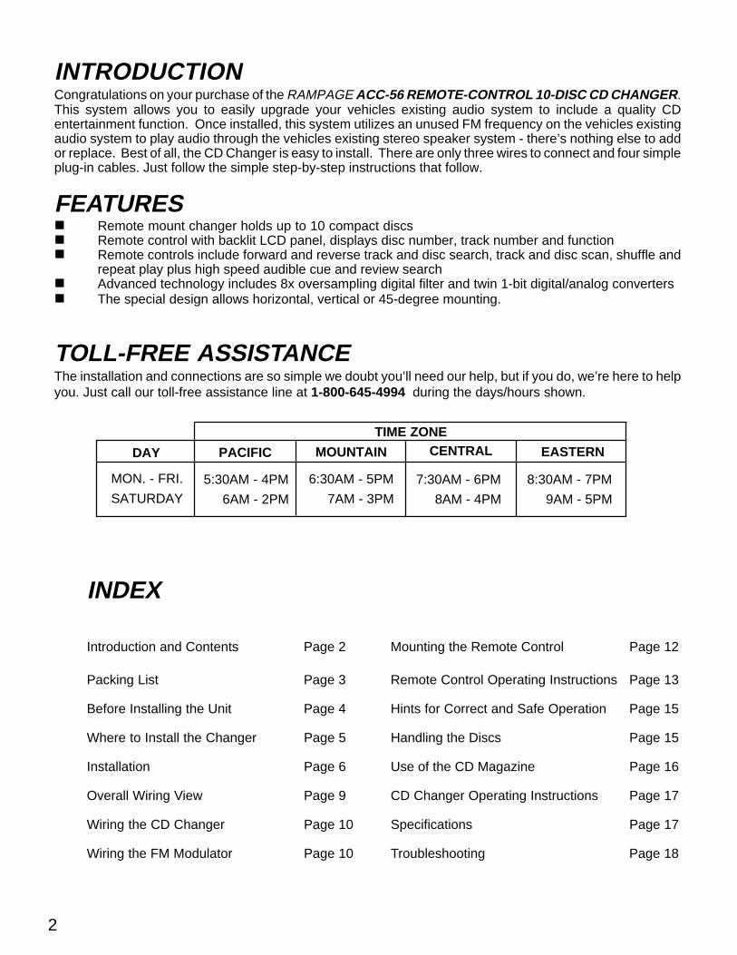
INTRODUCTIONCongratulations on your purchase of the RAMPAGE ACC-56 REMOTE-CONTROL 10-DISC CD CHANGER.This system allows you to easily upgrade your vehicles existing audio system to include a quality CDentertainment function. Once installed, this system utilizes an unused FM frequency on the vehicles existingaudio system to play audio through the vehicles existing stereo speaker system - there’s nothing else to addor replace. Best of all, the CD Changer is easy to install. There are only three wires to connect and four simpleplug-in cables. Just follow the simple step-by-step instructions that follow.
FEATURES� Remote mount changer holds up to 10 compact discs� Remote control with backlit LCD panel, displays disc number, track number and function� Remote controls include forward and reverse track and disc search, track and disc scan, shuffle and
repeat play plus high speed audible cue and review search� Advanced technology includes 8x oversampling digital filter and twin 1-bit digital/analog converters� The special design allows horizontal, vertical or 45-degree mounting.
TOLL-FREE ASSISTANCEThe installation and connections are so simple we doubt you’ll need our help, but if you do, we’re here to helpyou. Just call our toll-free assistance line at 1-800-645-4994 during the days/hours shown.
EASTERN
8:30AM - 7PM
9AM - 5PM
7:30AM - 6PM
8AM - 4PM
CENTRAL
6:30AM - 5PM
7AM - 3PM
MOUNTAINPACIFIC
5:30AM - 4PM
6AM - 2PM
MON. - FRI.
SATURDAY
DAY
TIME ZONE
2
INDEX
Introduction and Contents Page 2 Mounting the Remote Control Page 12
Packing List Page 3 Remote Control Operating Instructions Page 13
Before Installing the Unit Page 4 Hints for Correct and Safe Operation Page 15
Where to Install the Changer Page 5 Handling the Discs Page 15
Installation Page 6 Use of the CD Magazine Page 16
Overall Wiring View Page 9 CD Changer Operating Instructions Page 17
Wiring the CD Changer Page 10 Specifications Page 17
Wiring the FM Modulator Page 10 Troubleshooting Page 18
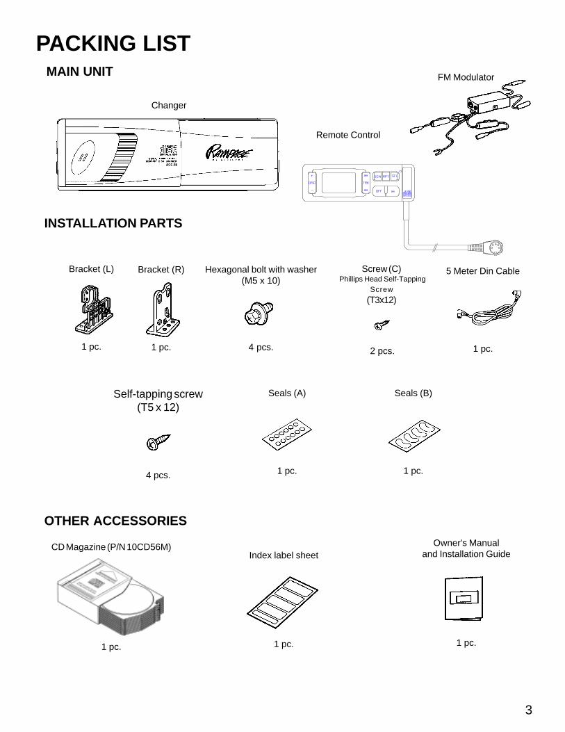
CD Magazine (P/N 10CD56M)
1 pc.
Index label sheet
1 pc.
Owner's Manualand Installation Guide
1 pc.
Self-tapping screw(T5 x 12)
4 pcs.
Seals (A)
1 pc.
5 Meter Din Cable
1 pc.
Hexagonal bolt with washer(M5 x 10)
4 pcs.
INSTALLATION PARTS
OTHER ACCESSORIES
MAIN UNIT
PACKING LIST
Changer
Bracket (L)
1 pc.
Bracket (R)
1 pc.
Seals (B)
1 pc.
3
FM Modulator
Remote Control
Screw (C) Phillips Head Self-Tapping
Screw
(T3x12)
2 pcs.
ACC-56

NOTE: If the changer is to be installed in a car that is equipped with an on-board drive or navigation computer, do notdisconnect the battery cable. If the cable is disconnected, the computer memory may be lost. Under theseconditions, use extra caution during installation not to cause a short circuit.
Do not install the unit in the following locations.� Locations exposed to direct sunlight.� Where hot air is discharged from the car heater.� In areas subject to extreme temperatures.
Incorrect installation can cause the disc to "skip" when playing. Be sure Mount the unit firmly in place, using the suppliedbrackets and screws.
� Be sure to use the supplied screws.� Be careful not to snag any wires when tightening screws.� Do not use any of the screws that are part of the brake or steering system, to install the unit.� Be careful not to damage the car wiring.
� This unit cannot be installed on its side, end, or upside down. Installation in such positions will cause malfunctioningof the mechanism.
Installation and Wiring Precautions
4
To prevent a short-circuit,� Be sure to turn off the ignition and remove the negative (-) battery cable, prior to installation.� Connect power wires last.
1
BEFORE INSTALLING THE UNITTransport Lock Screws
The mechanism in the CD changer is "locked" into place during shipment by threetransport lock screws. Be sure to remove the screws prior to installation.
� Caution �After removing the transport lock screws, place the supplied seals (A) over the screwholes. These seals are used to keep dust out of the unit, which could cause a malfunction.
4
3
2
TRANSPORT LOCK SCREWS(2 RIGHT SIDE, 1 LEFT SIDE)
ADDITIONAL 10-DISC MAGAZINESAdditional CD Magazines are available as an accessory item (Part No. 10CD56M). Visit the store where your ACC-56 waspurchased or, contact Audiovox directly for pricing and shipping information (1-800-645-4994). All checks or money ordersare to be made payable to Audiovox Electronics Corp. NOTE: Never send Cash when ordering.
Audiovox Electronics Corp.150 Marcus Blvd.Hauppauge, N.Y. 11788Attn: Parts Department
NOTE: New York residents, please include applicable sales tax.
REAR
BOTTOM FRONT
5

5
MOUNT ON FLOOR OF TRUNK(HORIZONTAL OR 45 DEGREES)
MOUNT ONSIDEWALL OFCARGO AREA
MOUNT ON BULKHEAD BEHINDSEAT OF PICKUP TRUCKS
MOUNT ON BACKWALLOF HATCH AREA
MOUNT ON SIDE OFTRUNK SIDEWALL
TRUNK MOUNTING (SEDANS)
This is usually the easiest location to use as there is ample spaceavailable. Check that you do not interfere with the removal of yourspare tire, etc. Observe caution on fuel tank stated above. Theonly negative aspect is the need to route the wiring from the trunkto your car dashboard.
HATCHBACKS, WAGONS & VANS
A simple investigation of the areas shown will often provideseveral possibilities. Observe caution on fuel tank stated aboveand make sure the unit is protected from cargo, passengerentry and exit, etc.
UNDER PASSENGER’S FRONTSEAT/BEHIND SEAT
If sufficient space and easy access exist, the area under thepassenger's front seat is ideal, and will also allow easy wiringaccess. However, you may need to temporarily remove the seatfor ease of installation. The area behind either the passenger’s ordriver’s seat on pickup trucks is another ideal location.
MOUNT UNDER LIP OF TRUNK
MOUNT UNDERSEAT
A few of the many mounting possibilities are shown below. The following precautions must be considered when selecting themounting location.Installation Cautions and Warnings:1. Fuel Tank - WARNING! Never install above your fuel tank as the holes you must drill may pierce the tank or the fuel lines.
Also check for other obstructions such as wires, etc.2. Excessive Heat - Avoid areas exposed to direct sunlight (on top of rear package shelf) or next to your car heater’s output
ducts.3. Ease of Use - Make certain the changer is easily accessible for loading and unloading the CD magazine.4. Distance - The data cable that joins the changer to the FM module is 15 feet long. Do not exceed this length.5. If mounting to a plastic surface, do not use the self-tapping screws provided. Use the bolts and hex nuts provided for
a more secure installation.IMPORTANT: Failure to properly secure the CD changer is the most common cause of all “skipping” and related
CD play problems. Changer must be mounted as explained on the following pages.
WHERE TO INSTALL THE CHANGER

6
INSTALLATIONThe ACC-56 changer is designed for horizontal (flat), vertical (upright) or 45-degree mounting. It must never be mounted upside-down or on either one of it's sides as explained previously. The position of the built-in anti-vibration springs (left and right side), mustcorrespond to the mounting position chosen. If the springs are not set correctly for the type of installation chosen, the anti-vibrationcompensation will not be effective and vibration may cause the disc to skip.
CAUTIONAfter setting the built-in anti-vibration springs, place the supplied Seals (B) over the holes. These seals are used to keep dust, which couldcause a malfunction, out of the unit.
Drill holes 4mm in diameter.
PROCEDURE FOR HORIZONTAL INSTALLATION1
2
3
Bracket (R)
Attach bracket (L) and bracket (R) to each side of the unit,using the hexagonal bolts with washer base (M5 x 10).
Determine the mounting location, and drill four mountingholes.
Secure the unit in place, using four self-tapping screws(T5 x 12).Use RTV (silicone sealer) on screw threads or aroundthe holes to prevent moisture intrusion.
Self-tapping screw (T5 x 12)
Never mount the unit near the fuel tank.
position "H"
position "V"
position "45°"
Bracket (L)
Bracket (R)
Bracket (L)
A n t i - v i b r a t i o nsprings position
NOTE: Use seals (A) to cover unusedmounting holes on sides of unit.
HORIZONTAL INSTALLATIONSet the 4 anti-vibration springs toposition "H".
VERTICAL INSTALLATIONSet the 4 anti-vibration springs toposition "V".
45° ANGLE INSTALLATIONSet the 4 anti-vibration springs toposition "45°".
Hexagonal boltwith washer base (M5 x 10)

7
PROCEDURE FOR VERTICAL INSTALLATIONNOTE:If the anti-vibration spring position has been changed and verified for vertical mounting (as shown on page 6), start with step 2.
Hexagonal boltwith washer base (M5 x10)
Bracket (R)
Bracket (L)
4
2 Attach bracket (L) and bracket (R) to each side of the unit,using the hexagonal bolts with washer base (M5 x 10).
Mount the unit in place, using four self-tapping screws(T5 x 12).Use RTV (silicone sealer) on screw threads or aroundthe holes to prevent moisture intrusion.
Set the 4 anti-vibration springs to position "V".
Determine the mounting location, and drill four mountingholes.
3
1
Never mount the unit near the fuel tank.
Drill holes 4 mm in diameter.
position "V"
Self-tapping screw(T5 x 12)
Bracket (R)
Bracket (L)
NOTE: Use seals (A) to cover unusedmounting holes on sides of unit.

8
PROCEDURE FOR 45° ANGLE INSTALLATIONNOTE:If the anti-vibration spring position has been changed and verified for 45° angle mounting (as shown on page 6), start with step 2.
4
2 Attach bracket (L) and bracket (R) to each side of the unit,using the hexagonal bolts with washer base (M5 x 10).
Mount the unit in place, using four self-tapping screws(T5 x 12).Use RTV (silicone sealer) on screw threads or aroundthe holes to prevent moisture intrusion.
Set the 4 anti-vibration springs to position "45°".
Determine the mounting location, and drill four mountingholes.
3
1
Never mount the unit near the fuel tank.
position "45°"
Bracket (L)
Bracket (R)
Hexagonal boltwith washer base (M5 x 10)
Drill holes 4mm in diameter.
Bracket (R)
Self-tapping screw (T5 x 12)
NOTE: Use seals (A) to cover unusedmounting holes on sides of unit.
Bracket (L)

9
OVERALL WIRING VIEWThis page is provided to give you a quick look at the entire wiring of the ACC-56. Use it to plan your wire routingpaths and possible connection points. Detailed wiring is explained in the following pages.
NOTE: When routing wires and cablesfrom the rear of the car to the dash-board, it is best to conceal the wiresunder carpeting. If you do not knowhow to do this, your local auto me-chanic or car stereo installer should beconsulted.
GREEN/WHTPOWER WIRE
ORANGE/WHTPOWER WIRE
TO CHASSISGROUND
BLACK GROUNDWIRE
FILTER BOX
2 AMP
5 AMPCONNECT TOCONSTANT+12 VDC SOURCE
CONNECT TOSWITCHED (RADIOOR ACCESSORY)+12 VDC SOURCE
10-DISC COMPACTDISC CHANGER
EXISTING CARSTEREO RADIO
REMOTE CONTROLCABLE (4-1/2 FEET)
DATA CABLE(15 FEET)
EXISTING RADIOANTENNA SOCKET
ANTENNA OUTPUT
ANTENNA INPUT
EXISTING CAR RADIOANTENNA CABLE
FM STEREOMODULATOR(89.1/88.7MHz)
REMOTECONTROLUNIT

10
WIRING THE FM MODULATORThe FM modulator should be positioned near your existingcar stereo and the 15 foot data cable should be connected to it.Make the following connections to the FM modulator:
DATA CABLEThe 15 foot data cable connects the changer to the FM module.First connect the end of the data cable labelled "TO CDCHANGER" to the 8-pin socket on the left side of the changer.Route the other end of the cable up to the car’s dashboard areanear your existing car radio and plug the data cable into the 8-pin mating socket on the end of the FM modulator.
WIRING THE CD CHANGER
ORANGE WITH WHITE STRIPE WIREAttached to the FM modulator is a 3-foot ACC Power wire(orange with white stripe). This is to be connected to a + 12volt circuit that is only live when the ignition is on. The bestconnection point is at the car’s fuse block at the “RADIO” or“ACCESSORY” identified terminals.
GREEN WITH WHITE STRIPE POWERWIREThe 3 foot +12 Constant Power wire (green with white stripe)must be connected to a live 12 volt wire in the vehicle. Youwill have to check the wire you connect it to and makecertain it is always live, even when the car’s ignition is turnedoff. If none is found, route the wire to the car’s fuse blockand connect it to a live circuit there.
15 FOOT DATA CABLE
"TO CD CHANGER"LABEL
CAR FUSE BLOCK
ORANGE w/WHITESTRIPE WIRE
15 FOOT EXTENSION LEAD(MAY NOT BE REQUIRED)
SPLICE INTO "LIVE" WIREAND TAPE SPLICE
EXISTING +12VOLT "LIVE" WIRE
"RADIO" OR "ACCESSORY"TERMINAL
FM MODULATOR
12 VOLTCAR BATTERY
FM MODULATOR
FM MODULATOR
GREEN w/WHITESTRIPE WIRE
FILTER BOX
5 AMP FUSE

CAR ANTENNA INPUTLocate your existing car radio antenna cable. This isnormally a black cable about as thick as a pencil andwill be plugged into a socket on the rear of your carradio. Unplug this antenna lead and plug it into themating female socket on the FM modulator.IMPORTANT - Some Import cars have a special dualantenna called “DIVERSITY ANTENNA”. If your carhas this type of antenna system, you will find theantenna cable will not fit the socket on the FM modu-lator. Use of the ACC-56 with “DIVERSITY ANTENNA"is not recommended. You may also find some latemodel GM cars have an antenna plug that is too smallto mate with the FM modulator. If this is found, callAudiovox’s Toll-Free Assistance for a special adapter(1-800-645-4994). This adapter can also be purchasedat any car stereo installation center.
RADIO ANTENNA OUTPUTAttached to the FM modulator is a male antenna plug.Simply plug this into the socket on the car radio fromwhich you just removed the car antenna cable.
REMOTE CONTROL CABLEAttached to your remote control is a cable that plugsinto the remaining 5-pin socket on the end of the FMmodulator. Position the remote control near the areayou will permanently mount it and route the cable to theFM modulator. Plug the cable into the FM modulator.
WIRING THE FM MODULATOR (con't.)
BLACK GROUND WIREThe 3 foot Ground wire (black) attached to the FMmodulator must be secured to a grounded metal partof the car’s chassis. If you cannot find an existing boltor screw to fasten it to, you must drill a hole in themetal and secure it with a screw. To insure a goodground, remove any paint or grease where the wirewill connect.
11
BLACK GROUND WIRE
EXISTINGSCREWOR BOLTGROUNDED METAL PART
OF CHASSIS
FM MODULATOR
FM MODULATOR
CAR RADIO
FEMALE CONNECTOR
FM MODULATOR
EXISTING CAR ANTENNA
EXISTING CAR RADIO(UNPLUG ANTENNA CABLE)
REMOTE CONTROL
CAR ANTENNA CABLE
MALE ANTENNA PLUG
FM MODULATOR
MALE ANTENNA PLUG
REMOTE CONTROL CABLE

12
MOUNTING THE REMOTECONTROL
On the back of the remote control you will find an adhesivebacked “Velcro” pad. Select the desired mounting area onyour car dashboard that will allow ease of use and fullvisibility of the LCD display. Peel off the protective paper onthe adhesive pad. Make certain the dash area is clean of allwax, grease, etc., and press the remote control in place.Allow a 1/2 hour for the adhesive to secure, then you will findthe Velcro pads will allow you to remove the remote controlfor hand-held use if desired and replace it as often asneeded.
MOUNTING THE FM MODULATOR
There are two mounting tabs on the FM modulator. It canbe secured by two methods. Use two screws “C” and drilltwo 3/32" holes or use electricians tape or twist ties (notprovided).
ADJUSTMENT OF FM MODULATORTUNING
To operate your ACC-56, your car radio must be first tunedto the FM band at 89.1MHz. If you find interference on thisfrequency, you can change the output frequency from theFM module to 88.7 MHz., by moving the slide switch on theFM modulator to the 88.7 MHz. position. You will then haveto tune your radio to 88.7 MHz instead of 89.1 MHz, whenusing your CD changer.
CAR DASHBOARD
CLEAN MOUNTING AREA
REMOTECONTROL
REMOVE PAPER LINERAND PRESS IN PLACE
DRILL TWO3/32" DIA. HOLES
MOUNTINGSURFACE
FM MODULATOR
SCREW"C"(2 PCS.)
SLIDESWITCH
FM MODULATOR
AUDIO LEVELADJUST

CONTROLSLCD Display
Track/Disc Scan (SCN)
Track/Disc Repeat (RPT)
Track/Disc Shuffle (SFL)
Reset Button
Play/Pause ( / II)
Power Off Switch (OFF)
Track (TRK) Select ( )
Track (TRK) Search ( )
Disc Select ( +/- )
PREPARING FOR OPERATION1. Load CD magazine ���and insert into changer as
described on page 16.2. Turn on your car ignition and your car stereo ���and
select “FM” band ��.3. Tune to 89.1 on the FM band ���unless you set the
selection switch on the FM module to 88.7; thentune to 88.7 on the FM band.
NOTE: You may find that it will be easier to useone of your presets specifically for CDoperation.
4. Press the Reset button �� on the remotecontrolusing a pencil tip or other thin pointed instrument.
NOTE: This is only required the First Time youuse the Changer.
5. Turn on the CD changer by pressing the Play/Pausebutton ��. The LCD panel � will illuminate and discnumber 1 will begin play.
6. Adjust your car radio’s volume, balance and tonecontrols for desired sound.
7. When the last track on disc 1 has played, the unitwill automatically advance to the next disc insequence and begin playing. This will continueuntil all discs have been played at which time theunit will begin playing disc number 1 again.
13
REMOTE CONTROL OPERATING INSTRUCTIONSUpon inserting a loaded CD magazine into the changer, the unit will begin automatically checking the magazine for the numberof discs loaded and their locations. This will occur even if the vehicle’s ignition is turned off. This process will take approximately45 seconds. During this time, the remote control function will be inoperative.
10
2
1
3
5
4
6
7
8
9
INTRO SCAN
SHUFFLE
SHFL
REPEAT
OFF
12
1314
11
FM 89.1
2 4
8
3
6
5
10
1
9 7
17
16
15

14
USE OF CONTROLS is provided to protect the unit's microprocessor and laserpickup system and should only be activated under thefollowing circumstances:1. Initial installation after all wiring is completed (this must be
done).2. If abnormal disc operation is encountered, the reset button
may be pressed to clear the system and return to normaloperation.
IMPORTANT: Use of the Reset button on the CD Changerwill cause the CD magazine to be automatically ejected.Make certain changer door is fully opened prior to usingReset.
� PLAY/PAUSE ( / ) BUTTON
Pressing this button turns on the CD changer, illuminates theLCD panel and begins play of disc #1 if a new CD magazinehas been loaded into the changer. If a magazine was alreadyin the changer, play will resume from the track on the discpreviously in play. Play of the disc is shown by the indication and the rotating disc symbol on the LCD panel. Pressingthe button again will temporarily stop play of the disc. Thepause indication will appear on the LCD panel and the discsymbol will stop rotating and flash instead. Press the buttonagain to resume play of the disc.NOTE: If left in the PAUSE mode for 5 minutes, the unit will
automatically shut off.
��POWER OFF SWITCH (OFF)
Press this switch to turn the CD changer off and return tonormal FM reception.
� TRACK SELECT ( )
The Track Select function is used to quickly access thebeginning of a particular track. Press Forward Track Select( ) or Backward Track Select ( ) to locate the desiredtrack as shown by the track number indication on the LCDpanel.
��TRACK SEARCH ( )
High-speed audible search to any section of the disc can bemade by the search functions. Press and hold the buttonto advance quickly in the forward direction or press and holdthe button to advance rapidly in the backward direction.During search operation, the rotation disc symbol will turnfaster and the appropriate symbol or will flash on theLCD panel. When the forward search button is held downand end of the last track is reached, or the backward search is held down and the unit reaches the beginning of thefirst track on the disc, the unit will enter the Pause mode untilthe button is released.
�� DISC +/- SELECT BUTTONPress the DISC select button to select the desired disc forplay as shown on the LCD panel. The unit will automaticallyload the selected disc and begin play. To advance to ahigher number disc, press the + side of the button. Toreturn to a lower number, press the - side.
��LCD DISPLAY
The LCD Display Panel will illuminate when the CD changer isoperating. Different symbols will appear depending on thefunction and operation in use. Each functional display isexplained in the following paragraphs.
�TRACK/DISC SCAN (SCN)
When the Scan button is pressed, the indication SCN willappear on the LCD panel and the first 10 seconds of each trackon the disc will be played in order. When a desired track isreached, press the Scan button again and play of that track willcontinue (SCN will disappear from the display). Scan mode willbe cancelled by activating any other function (Repeat, Shuffle,Disc Select, Track Select, or Track Search).When the Scan button is pressed and held for longer than 2seconds, the SCN and DISC indications will appear on the LCDpanel and the first 10 seconds of the first track of each disc in themagazine will be played. When a desired disc is reached, pressthe Scan button again and play of that disc will continue (SCNand DISC will disappear from the display). Disc Scan mode willalso be cancelled by activating any other function (Repeat,Shuffle, Disc Select, Track Select, or Track Search).
�TRACK/DISC REPEAT (RPT)
When the Repeat button is pressed, the indication RPT willappear on the LCD panel and play of the selected track will becontinuously repeated until the Repeat mode is cancelled bypressing the Repeat button again or by activating the Scan 9 orShuffle 7 functions.When the Repeat button is pressed and held longer than 2seconds, the RPT and DISC indications will appear on the LCDpanel and play of the selected disc will be continually repeateduntil the Disc Repeat mode is cancelled by pressing the Repeatbutton again or by activating the Scan 9 or Shuffle 7 functions.
� TRACK/DISC SHUFFLE (SHF)
When the Shuffle button is pressed, the indication SHF willappear on the LCD panel and the tracks on the disc will beplayed in a random, shuffled order. The Track Skip 5 functionwill also select tracks in the shuffled order instead of the normalprogression. The Track Shuffle mode can be cancelled bypressing the Shuffle again, or by activating the Scan 9 or Repeat8 functions.When the Shuffle button is pressed and held longer than 2seconds, the SHF and DISC indications will appear on the LCDpanel and the discs in the magazine will be played in a randomshuffled order, as well as the tracks on each disc. When all thetracks on the selected disc have been played, the next disc willbe selected in shuffled order and its tracks will be played inshuffled order. The Disc Shuffle mode can be cancelled bypressing the Shuffle button again, or by activating the Scan 9 orRepeat 8 functions.
��RESET BUTTON
A reset button is located on the front panel of the remote controlwhich must be activated with a pen or other thin object as it isrecessed to prevent accidental engagement. The reset circuitry

This CD Changer is designed to be operated only on 12 volt DC negative ground systems. The unit cannot be used on 24 voltor positive ground systems.
TEMPERATUREThe unit may not operate correctly in extremely hot or cold temperatures. It is equipped with a built-in thermal protection circuitwhich will stop operation of the unit when the temperature reaches the preset level. If this should happen, the unit will resumeoperation when the vehicle returns to a normal temperature range.
Remove the magazine from the unit when it is not being used during hot weather. If the discs are left in an extremely hot carthey may warp. If the CD changer is not used for long periods of time, remove the compact discs from the magazine, andstore them in their cases.
CONDENSATIONMoisture can condense on the laser lens of the CD changer during rainy and humid days, or right after the heater is turned onin the car (if the changer is mounted in the passenger compartment). If this should happen the unit will not operate correctly.To remedy the situation, remove the discs from the unit and wait approximately one hour. During this time the moisture willevaporate and the unit will operate normally.
INTERRUPTIONS IN SOUND (Skipping)The sound from the unit may "skip" and be interrupted if the anti-vibration springs are not set correctly, if the changer is mountedon-end or upside-down, or when travelling on very rough road surfaces. If this should occur, check for errors made duringinstallation or wait for the road surface to improve.
3" (8cm) CD-SINGLESThis unit is not designed to play 3" (8cm) CD-Single discs. Inserting a 3" disc into the magazine, either with or without a 3" discadaptor, can damage the changer and the disc. Such damage will not be covered by the Warranty on this product.
HANDLING THE DISCSDirt, dust, scratches and warpage cause sound skips during playback and a deterioration of sound quality. To take proper careof your discs:
1. Use compact discs that have the logo.
2. Fingerprints and dust should be carefully wiped off the disc's signal surface (glossy side) with a soft cloth. Unlikeconventional records, the compact disc has no grooves to collect dust and microscopic debris, so gently wiping witha soft cloth should remove most particles. Wipe in a straight motion from the inside to the outside of the disc. Smalldust particles or light stains will have absolutely no effect on reproduction quality.
3. Never use such chemicals as record sprays, antistatic sprays or fluids, benzine or thinner to clean compact discs. Suchchemicals could irreparably damage the disc's plastic surface.
4. Discs should be put back in their cases after use to avoid serious scratches that could cause the sound to skip.
5. Do not expose discs to direct sunlight, high humidity, or high temperatures for extended periods of time. Long exposureto high temperatures can warp the disc.
6. Do not stick paper, labels, or tape on the disc surface.
7. Do not write with any type of pen, pencil, or marker on the disc surface.
8. To minimize fingerprints and smudges on the signal surface, always try to hold the discs by their outer edge and center hole.
HINTS FOR CORRECT AND SAFE OPERATION
15
CAUTION: When the CD magazine is ejected by the use of the Reset button, whichever disc was in play prior to pressingReset will be left in the play position in the changer. It is critical that before reinserting the CD magazine, youmust REMOVE ALL DISCS from it. After you have inserted the empty CD magazine, press EJECT on the changerand the "in play" disc will be loaded into the empty magazine. You may then remove the magazine and reload asmany discs as desired.
WARNING: Avoid use of Reset button after initial use unless you have a definite abnormal disc operation. Use the EJECTbutton on the changer to remove the CD magazine for normal operation.

LOADING DISCS INTO THE MAGAZINEThis CD Changer uses a specially-designed magazine to holdup to 10 compact discs. To load discs into the magazine, gripthe tab on the magazine tray into which you will be loading adisc and pull it out gently as shown in Figure 1. Pull out only onetray at a time. Insert a disc into the tray with the label side down(play surface facing up) as shown in Figure 2. Push the trayback into the magazine as shown in Figure 3. Load discs intothe remaining 9 trays in a similar manner.
REMOVING DISCS FROM THE MAGAZINETo remove a disc from the magazine, pull out the tray of the discto be removed, lift out the disc, and push the tray back into themagazine.
USE OF THE CD MAGAZINE
NOTES:
Fig. 3
Fig. 2
Fig. 1
Playing Surface Up
Avoid touching the playing side of the disc.Only one disc can be inserted into each tray of the maga-zine. Do not try to insert more than one disc into each trayas damage to the discs and magazine may occur.This changer is not designed to play 3" CD-Single discs(8cm). Inserting a 3" disc into the magazine, either withor without a 3" disc adaptor, can damage the changer andthe disc. Such damage will not be covered by the Warrantyon this product.Additional CD magazines are available as accessory itempart number 10CD56M from your Audiovox dealer, or youmay contact us directly at:
�
�
�
�
LOADING THE MAGAZINE INTO THE CHANGERCompletely slide the door on the changer to the right as shown inFigure 4. Making sure the top of the magazine is facing upward,gently insert it into the unit until it clicks into place, as shown in Figure5. Slide the door of the changer fully closed and the unit is ready foroperation.
REMOVING THE MAGAZINE FROM THE CHANGERThe magazine can be removed from the changer using one of twomethods as outlined below in steps 1 and 2.
NOTE: Be sure to keep the door on the changer closed at all timeswhen not loading or removing the magazine. Leaving the door opencould allow dust, dirt and moisture to enter the changer which couldcause the unit to malfunction.
1. During normal operation with power applied, slide open thedoor on the changer and press the eject button as shownin Figure 6. The magazine will eject and can be removed.
2. If the magazine will not eject in a normal manner, removepower by disconnecting the DIN cable from the changer.a. Slide open the magazine door. On the bottom left rear of
the changer, as shown in Figure 5, peel off the tapecovering the access hole; insert a thin-bladed screwdriverinto the access hole and engage the mechanical releasearm.
b. Lightly leverage the blade to the right and the magazine willdisengage and be ejected.
16
Fig. 4
Fig. 5
Fig. 6
EJECT BUTTON
MANUAL MAGAZINERELEASE (BOTTOMLEFT CORNER)

CD CHANGER OPERATING INSTRUCTIONS
This CD Changer is designed to operate through a compatible Audiovox car stereo which incorporates thecontrols and display functions or through the FM section of any car stereo. Please check with your Audiovoxstereo specialist for recommendations of the models that will work with this changer. The specific operatinginstructions for the changer will be contained within the Owner's Manual of the compatible unit.
SPECIFICATIONS:
Changer:
Frequency Response: 5 - 20,000 Hz ±1dB
Distortion: 0.008% @ 1kHz
Dynamic Range: 95 dB
Signal-to-Noise Ratio: 95 dB
Channel Separation: 70 dB @ 1kHz
Wow & Flutter: below measurable limits
Dimensions: 9-5/8" W x 3-3/8" H x 6-7/8" D245 mm x 85 mm x 174 mm
Operating Voltage: 12 Volts DC, negative ground
Current Drain: 800mA (Playback/loading/ejecting)
FM Modulator:
Output Frequency: 88.7/89.1 MHz (Switchable)
Accessories Supplied: 10-disc magazine, P/N 10CD56MMounting hardware (1set)Connecting cable (1ea.)
17

TROUBLESHOOTING
An error made in operation or during installation of this product may be mistaken for a system malfunction. Please performthe checks described below before contacting your dealer or service facility.
No power
Magazine cannot beinstalled
CD is not played
Noise, skipping, orintermittent soundduring playback.
Possible Cause RemedySymptom
Check fuses in vehicle fuse box and changer system.Replace as necessary with fuse of same type andrating as original. If fuse blows again, consult withservice facility.
Check all wiring and correct as necessary.
Insert magazine in proper direction.
Load disc correctly in the magazine.
Check sound on another disc. If sound from seconddisc is OK, first disc is defective.
Clean disc
Remove the transit screws from sides of the unit.
Set the mounting angle adjustment to the correctposition as per the installation instructions.
Blown fuse
Incorrect connection
Magazine is inserted in wrongdirection.
Disc is loaded incorrectly in magazine.
Scratches on disc or warped disc
Extremely dirty disc
Transit screws still in place
Mounting angle adjustment is notcorrect.
18

AUDIOVOX CORPORATION (the Company) warrants to the original retail purchaser of this productthat should this product or any part thereof, under normal use and conditions, be proven defectivein material or workmanship within 12 months from the date of original purchase, such defect(s) willbe repaired or replaced with new or reconditioned product (at the Company's option) without chargefor parts and repair labor.
To obtain repair or replacement within the terms of this Warranty, the product is to be delivered withproof of warranty coverage (e.g. dated bill of sale), specification of defect(s), transportation prepaid,to the warranty center at the address shown below.
This Warranty does not extend to the elimination of car static or motor noise, to correction of antennaproblems, to costs incurred for installation, removal, or reinstallation of the product, or damage totapes, compact discs, speakers, accessories, or vehicle electrical systems.
This Warranty does not apply to any product or part thereof which, in the opinion of the Company,has suffered or been damaged through alteration, improper installation, mishandling, misuse,neglect, accident, or by removal or defacement of the factory serial number/bar code label(s). THEEXTENT OF THE COMPANY'S LIABILITY UNDER THIS WARRANTY IS LIMITED TO THEREPAIR OR REPLACEMENT PROVIDED ABOVE AND, IN NO EVENT, SHALL THE COMPANY'SLIABILITY EXCEED THE PURCHASE PRICE PAID BY PURCHASER FOR THE PRODUCT.
This Warranty is in lieu of all other express warranties or liabilities. ANY IMPLIED WARRANTIES,INCLUDING ANY IMPLIED WARRANTY OF MERCHANTABILITY, SHALL BE LIMITED TO THEDURATION OF THIS WRITTEN WARRANTY. ANY ACTION FOR BREACH OF ANY WARRANTYHEREUNDER INCLUDING ANY IMPLIED WARRANTY OF MERCHANTABILITY MUST BEBROUGHT WITHIN A PERIOD OF 30 MONTHS FROM DATE OF ORIGINAL PURCHASE. IN NOCASE SHALL THE COMPANY BE LIABLE FOR ANY CONSEQUENTIAL OR INCIDENTALDAMAGES FOR BREACH OF THIS OR ANY OTHER WARRANTY, EXPRESS OR IMPLIED,WHATSOEVER. No person or representative is authorized to assume for the Company any liabilityother than expressed herein in connection with the sale of this product.
Some states do not allow limitations on how long an implied warranty lasts or the exclusion orlimitation of incidental or consequential damage so the above limitations or exclusions may not applyto you. This Warranty gives you specific legal rights and you may also have other rights which varyfrom state to state.
12 MONTH LIMITED WARRANTY
U.S.A. : AUDIOVOX ELECTRONICS CORPORATION, 150 MARCUS BLVD., HAUPPAUGE, NEW YORK 11788�� 1-800-645-4994
CANADA: CALL 1-800-645-4994 FOR LOCATION OF WARRANTY STATION SERVING YOUR AREA 128-4270E

© 2002 Audiovox Electronics Corp., Hauppauge, NY 11788 Printed in China
128-6265B


