14
Submittal Data English Language/IP Units SD1568EW 10/14 Aurora Universal Protocol Converter (UPC)

Submittal DataEnglish Language/IP Units
SD1568EW 10/14
Aurora Universal Protocol Converter (UPC)
©2014 The manufacturer has a policy of continual product research and development and reserves the right to change design and specifi cations without notice.
Contractor: P.O.:
Engineer:
Project Name: Unit Tag:
SD1568EW 10/14 1 Page _____ of _____
Aurora Universal Protocol Converter (UPC) Submittal
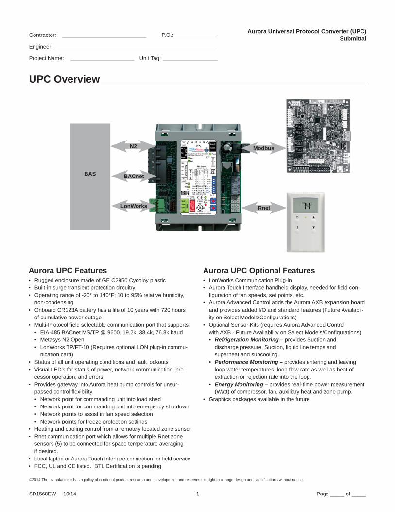
UPC Overview
Aurora UPC Features• Rugged enclosure made of GE C2950 Cycoloy plastic• Built-in surge transient protection circuitry• Operating range of -20° to 140°F; 10 to 95% relative humidity,
non-condensing• Onboard CR123A battery has a life of 10 years with 720 hours
of cumulative power outage • Multi-Protocol field selectable communication port that supports:
• EIA-485 BACnet MS/TP @ 9600, 19.2k, 38.4k, 76.8k baud • Metasys N2 Open• LonWorks TP/FT-10 (Requires optional LON plug-in commu-
nication card)• Status of all unit operating conditions and fault lockouts • Visual LED’s for status of power, network communication, pro-
cessor operation, and errors• Provides gateway into Aurora heat pump controls for unsur-
passed control flexibility• Network point for commanding unit into load shed• Network point for commanding unit into emergency shutdown• Network points to assist in fan speed selection• Network points for freeze protection settings
• Heating and cooling control from a remotely located zone sensor• Rnet communication port which allows for multiple Rnet zone
sensors (5) to be connected for space temperature averagingif desired.
• Local laptop or Aurora Touch Interface connection for field service• FCC, UL and CE listed. BTL Certification is pending
N2
BACnet
LonWorks
BAS
Rnet
Modbus
Aurora UPC Optional Features• LonWorks Communication Plug-in• Aurora Touch Interface handheld display, needed for field con-
figuration of fan speeds, set points, etc.• Aurora Advanced Control adds the Aurora AXB expansion board
and provides added I/O and standard features (Future Availabil-ity on Select Models/Configurations)
• Optional Sensor Kits (requires Aurora Advanced Controlwith AXB - Future Availability on Select Models/Configurations)• Refrigeration Monitoring – provides Suction and
discharge pressure, Suction, liquid line temps andsuperheat and subcooling.
• Performance Monitoring – provides entering and leaving loop water temperatures, loop flow rate as well as heat of extraction or rejection rate into the loop.
• Energy Monitoring – provides real-time power measurement (Watt) of compressor, fan, auxiliary heat and zone pump.
• Graphics packages available in the future

©2014 The manufacturer has a policy of continual product research and development and reserves the right to change design and specifi cations without notice.
Contractor: P.O.: Engineer:
Project Name: Unit Tag:
SD1568EW 10/14 2 Page _____ of _____
Aurora Universal Protocol Converter (UPC) Submittal
UPC Physical Data
OverallA 5-3/16” 13.2 cm
B 4-1/8” 10.5 cm
Mounting HoleDimensions
C 4-7/8” 12.4 cm
D 2-1/20” 5.2 cm
E 3/16” 0.5 cm
Depth 1-9/16” 4.0 cm
Weight 0.44 lbs 0.2 kg

©2014 The manufacturer has a policy of continual product research and development and reserves the right to change design and specifi cations without notice.
Contractor: P.O.: Engineer:
Project Name: Unit Tag:
SD1568EW 10/14 3 Page _____ of _____
Aurora Universal Protocol Converter (UPC) Submittal
UPC Electrical Data
Power 24 Vac ± 10%, 50 to 60 Hz, 10 VA power consumption
(16 VA with Aurora Touch Interface attached)
26 Vdc (25 V min, 30 V max)
Single Class 2 source only, 100 VA or less
Physical Rugged GE C2950 Cycoloy plastic.
Operating Range -20° to 140°F (-29° to 60°C); 10 to 95% relative humidity, non-condensing
Communication Ports Port 1a: Jumper-configurable for ARC156 or EIA-485 communication. In ARCNET
mode, the port speaks BACnet (at 156k bps). In EIA-485 mode, the
communication protocol and baud rate desired are DIP switch selectable
between BACnet MS/TP, or N2
Port 2: Used for Aurora communications
RNET: Local laptop and/or Aurora Touch Interface access port
Optional Card Port LonWorks Option Card for connection to Free Topology LON networks
(TP/FT-10 Channel)
Status Indication Visual (LED) status of power, network communication, running, and errors
Battery Battery CR123A has a life of 10 years with 720 hours of cumulative power outage
Protection Built-in surge transient protection circuitry. Controller protected by internal solid
state Polyswitches on incoming power and network connections. Polyswitches do
not need to be replaced, as they will reset themselves once the condition that
caused them to “trip” returns to normal.
BACnet supportConforms to the Advanced Application Controller (B-AAC) Standard Device Profile as defined in ANSI/ASHRAE Standard 135-2004 (BACnet) Annex L
BACnet Certification BTL Certification is pending
Listed by FCC, UL, cUL, and CE listed. UL916 (Canadian Std C22.2 No. 205-M1983, CE, FCC Part 15 - Subpart B - Class A

©2014 The manufacturer has a policy of continual product research and development and reserves the right to change design and specifi cations without notice.
Contractor: P.O.: Engineer:
Project Name: Unit Tag:
SD1568EW 10/14 4 Page _____ of _____
Aurora Universal Protocol Converter (UPC) Submittal
UPC Compliance
Serial Number If you need the UPC’s serial number when troubleshooting, the number is on: • a sticker on the back of the main translator board • a Module Status report (modstat) from WebCTRL , or thru the
Aurora Touch Interface by accessing the “Module Setup” menu.
FCC Compliance
This equipment has been tested and found to comply with the limits for a Class A digital device, pursuant to Part 15 of the FCC Rules. These limits are designed to provide reasonable protection against harmful interference when the equipment is operated in a commercial environment. This equipment generates, uses, and can radiate radio frequency energy and, if not installed and used in accordance with the instruction manual, may cause harmful interference to radio communications. Operation of this equipment in a residential area is likely to cause harmful interference in which case the user will be required to correct the interference at his own expense.
CAUTION: Changes or modifications not expressly approved by the responsible party for compliance could void the user’s authority to operate the equipment.
CE Compliance
The Aurora UPC conforms to the following standards. A full Decla-ration of Conformity is available on request.
Electromagnetic Emissions: EN55022: 1994 Class AElectromagnetic Compatibility:Immunity for Commercial Environments EN61000-6-1: 2007Electrostatic Discharge: EN61000-4-2: 2008Radiated Electromagnetic Field: EN61000-4-3: 2010Electronic Fast Transient/Burst Requirements: EN6100-4-4: 2004Surge Immunity: EN6100-4-5: 2005Immunity to Conductive Disturbance: EN6100-4-6: 2008Power Frequency Magnetic Field Immunity: EN6100-4-8: 2009Immunity to Voltage Dips and Variations EN6100-4-11: 2004European Low Voltage DirectiveRestriction of the Use of Certain Hazardous Substances (RoHS)
BACnet Compliance
BACnet® is a registered trademark of ASHRAE. ASHRAE does not endorse, approve or test products for compliance with ASHRAE standards. Compliance of listed products to require-ments of ASHRAE Standard 135 is the responsibility of the BAC-net manufacturers Association (BMA). BTL certification is pending. BTL® is a registered trademark of the BMA.
If Run LED shows... And Error LED shows... Status is...
2 flashes per second Off Normal
2 flashes per second On Exec halted after frequent system errors, due to:
• Controller halted
• Program memory corrupted
• Address conflicts - duplicate MS/TP MAC addresses
• One or more programs stopped
5 flashes per second On Exec start-up aborted, Boot is running
5 flashes per second Off Firmware transfer in progress, Boot is running
7 flashes per second7 flashes per second, alternat-ing with Run LED
Ten second recovery period after brownout
14 flashes per second14 flashes per second, alter-nating with Run LED
Brownout
On On Failure. Try the following solutions:
• Turn the UPC off, then on.
• Download memory to the UPC.
• Replace the UPC.

©2014 The manufacturer has a policy of continual product research and development and reserves the right to change design and specifi cations without notice.
Contractor: P.O.: Engineer:
Project Name: Unit Tag:
SD1568EW 10/14 5 Page _____ of _____
Aurora Universal Protocol Converter (UPC) Submittal
UPC I/O Description
The Aurora UPC can be applied in two control systems: Aurora Base (ABC board only) or the Aurora Advanced (ABC plus the AXB expansion board). The following table illustrates the possible I/O with the two control schemes and the following text describes the I/O operation and point name.
Auro
ra U
PC -
I/OUP
C wi
th
Auro
ra B
ase
UPC
with
Aur
ora
Adva
nced
Netw
ork C
onfig
urab
leHa
rdwa
re
Ref #
Desc
riptio
nUs
esSt
d Co
nfig
(PCB
Lab
eling
)PC
B Lo
catio
nUP
C + A
BC O
nly
UPC
+ ABC
+ AX
B Ex
pans
ion
Boar
dFa
ctor
y, Fi
eld In
stall
ed
Analo
g In
Desc
riptio
nsUs
esSt
d Co
nfig
PCB
1Le
aving
Air T
empe
ratur
eLe
aving
Air T
empe
ratur
eFP
2AB
C√
√St
anda
rd P
rogr
amST
D- F
acto
ry in
stall
ed S
enso
rLe
aving
Wate
r Tem
pera
ture
Leav
ing W
ater T
empe
ratur
eLW
TAX
B√
Stan
dard
Pro
gram
Enter
ing W
ater T
empe
ratur
eEn
tering
Wate
r Tem
pera
ture
EWT
AXB
√St
anda
rd P
rogr
amAl
t Lea
ving A
ir Tem
pera
ture
Alt L
eavin
g Air T
empe
ratur
eLA
TAX
B√
Stan
dard
Pro
gram
Flow
Meter
InFlo
w Me
ter In
Flow
AXB
√St
anda
rd P
rogr
amHt
g Liqu
id Lin
e Tem
pera
ture
Htg L
iquid
Line T
empe
ratur
eLL
TAX
B√
Stan
dard
Pro
gram
Disc
harg
e Pre
ssur
eDi
scha
rge P
ress
ure
Disc
hAX
B√
Stan
dard
Pro
gram
Sucti
on Te
mper
ature
Sucti
on Te
mper
ature
SCT
AXB
√St
anda
rd P
rogr
amSu
ction
Pre
ssur
eSu
ction
Pre
ssur
eSC
PAX
B√
Stan
dard
Pro
gram
Comp
ress
or C
urre
nt 1
Comp
ress
or C
urre
nt 1
CC1
AXB
√St
anda
rd P
rogr
amCo
mpre
ssor
Cur
rent
2Co
mpre
ssor
Cur
rent
2CC
2AX
B√
Stan
dard
Pro
gram
Fan C
urre
ntFa
n Cur
rent
FCAX
B√
Stan
dard
Pro
gram
Aux C
urre
ntAu
x Cur
rent
ACAX
B√
Stan
dard
Pro
gram
Digi
tal In
Desc
riptio
nsUs
esSt
d Co
nfig
PCB
2Co
mpre
ssor
Pro
ving
Comp
ress
or P
rovin
gY1
ABC
√√
Stan
dard
Pro
gram
Fact
ory I
nsta
lled
Optio
n3
Valve
End
Swi
tchVa
lve E
nd S
witch
Y2AB
C√
√St
anda
rd P
rogr
amFi
eld In
stall
ed O
ptio
n4
Fan p
rovin
gFa
n pro
ving
GAB
C√
√St
anda
rd P
rogr
amFc
try O
ptio
n-re
quire
d fo
r E H
eat
5Ro
om O
ccup
ancy
Sen
sor I
nput
Occu
panc
y Sen
sor
OAB
C√
√St
anda
rd P
rogr
amFi
eld In
stall
ed O
ptio
n6
Dirty
Filte
r Inp
utDi
rty F
ilter S
witch
WAB
C√
√St
anda
rd P
rogr
amFi
eld In
stall
ed O
ptio
nAl
arm
sDe
scrip
tions
Uses
PCB
7Di
ffere
ntiate
d Alar
msAl
l ABC
/AXB
Alar
msAB
C√
√NA
Thru
UPC
8En
glish
Alar
m De
scrip
tion
In En
glish
ABC
√√
NATh
ru U
PCDi
gita
l Out
Desc
riptio
nsUs
esSt
d Co
nfig
PCB
9Al
arm
Con
tact R
elay R
1Dr
y Alar
m/24
VAC
Alar
mAB
C√
√Fi
eld S
witc
habl
e and
Inst
alled
(exc
ept R
ehea
t Mod
els)
10Ac
cess
ory R
elay 1
- Dr
y Con
tact R
elay R
2
(Sele
ctable
oper
ation
)
-Sole
noid
Valve
w/ D
elay
-
Damp
er w
/Fan
-
Damp
er w
/Com
pres
sor
ACC1
ABC
√√
Netw
ork C
onfig
urab
le
-So
lenoi
d Va
lve w
/ Dela
y (Fc
ty)
-Cl
ose w
/Fan
-Cl
ose w
/Com
pres
sor
Field
or F
acto
ry in
stall
ed p
ump/
solen
valve
with
dela
y
11El
ectric
Hea
t 1EH
stag
e 1EH
1 - D
C Ou
tAB
C√
√St
anda
rd P
rogr
amW
F EH
eat R
eady
or R
elay K
it fo
r Oth
er E
heat
12El
ectric
Hea
t 2EH
stag
e 2EH
2 - D
C Ou
tAB
C√
√Ne
twor
k Con
figur
able
DOFi
eld In
stall
ed R
elay K
it
13Ac
cess
ory R
elay 2
- Dr
y Con
tact R
elay
(S
electa
ble op
erati
on)
-Sole
noid
Valve
-Da
mper
w/F
an
-Da
mper
w/C
ompr
esso
rK3
- ACC
2AX
B√
EH2 o
r DO
usin
g Re
lay K
itFi
eld S
witc
habl
e and
Inst
alled
Analo
g Ou
tDe
scrip
tions
Uses
Std
Conf
igPC
B14
Modu
lating
t Reh
eat
Modu
lating
Valv
e 0-1
0V
None
AXB
√Ne
twor
k Con
figur
able
Analo
g Ou
t 0-1
0V
Spec
ialty
I/ODe
scrip
tions
Uses
Std
Conf
igPC
B
15Va
riable
Spe
ed P
ump/M
od V
alve -
PW
M Ou
t VS
Pum
p/ Mo
d Valv
eVS
Pum
pAX
B√
Stan
dard
Pro
gram
Field
inst
alled
Opt
ion
16Lo
op P
ump S
laving
Slav
ing O
ther A
uror
a Unit
sPu
mp S
lave
AXB
√St
anda
rd P
rogr
amFi
eld In
stall
ed O
ptio
n
Optio
nal P
erfo
rman
ce M
onito
ring
Fact
ory I
nsta
lled
Kit
Optio
nal R
efrig
erat
ion
Moni
torin
g Fa
ctor
y Ins
talle
d Ki
t
Optio
nal E
nerg
y Mon
itorin
g Fa
ctor
y Ins
talle
d Ki
t
17 18 19
Performance
Kit
Refrigeration
Kit
Energy Monitoring
Kit

©2014 The manufacturer has a policy of continual product research and development and reserves the right to change design and specifi cations without notice.
Contractor: P.O.: Engineer:
Project Name: Unit Tag:
SD1568EW 10/14 6 Page _____ of _____
Aurora Universal Protocol Converter (UPC) Submittal
UPC with Aurora Base Control (ABC Board Only)1. Leaving Air Temperature (LAT) Sensor – This 10 kOhm NTC sen-
sor is factory installed on all UPC equipped heat pumps. It typically is attached to wiring inside the blower cabinet on the suction side of the blower. This sensor is attached on ABC FP2 pins available as LAT AV-30.
2. Compressor Proving Sensors – This optional factory installed current sensor is connected to confirm compressor operation via the power wires. The sensor is attached at ABC Y1 and available at point BV-65.
3. Valve End Switch – This optional input is setup for a field installed flow valve end switch. This end switch input is attached at ABC Y2 and available at point BV-67.
4. Fan Proving Sensors – This optional factory installed current sensor is connected to confirm fan operation via the power wires. The sen-sor is attached at ABC G and available at point BV-33.
5. Occupancy Sensor - This optional field installed and wired room sensor and occupancy sensor are typically found in DDC systems. The occupancy Sensors are attached at ABC 0 and can be found at point BV-49.
6. Dirty Filter Switch – This optional field installed switch is connected to confirm dirty filter operation. The dirty filter switch can be found
through your commercial representative. The sensor is attached at ABC W and available at point BV-63.
7. Fault, Configuration, and Status Codes – The codes can be visible to the BAS if desired
Fault LED (LED1, Red)
Red Fault LED LED Flash Code* Lockout Reset/
Remove
AB
C B
asic
Fau
lts
Normal - No Faults OFF –Fault - Input 1 No AutoFault - High Pressure 2 Yes Hard or SoftFault - Low Pressure 3 Yes Hard or SoftFault - Freeze Detection FP2 4 Yes Hard or SoftFault - Freeze Detection FP1 5 Yes Hard or SoftFault - Loss of Charge 6 Yes AutoFault - Condensate Overflow 7 Yes Hard or SoftFault - Over/Under Voltage 8 No AutoFault - FP1 & FP2 Sensor Error 11 Yes Hard or Soft
NOTE: All codes >11 use long flash for tens digit and short flash for the ones digit. 20, 30, 40, 50, etc. are skipped.
Aurora Base Fault Codes (ABC Only)
Aurora Advanced Fault Codes (ABC + AXB Expansion Board) - Future Availability Fault LED (LED1, Red)
FaultRed Fault
LED *BAS Fault Code (Aurora UPC)
LockoutReset/
RemoveFault Condition Summary
AB
C B
asi
c F
au
lts
Normal - No Faults Off 0 -Fault-Input 1 1 No Auto Tstat input error. Autoreset upon condition removal.
Fault-High Pressure 2 2 YesHard or
SoftHP switch has tripped (>600 psi)
Fault-Low Pressure 3 3 YesHard or
SoftLow Pressure Switch has tripped (<40 psi for 30 continuous sec.)
Fault-Freeze Detection FP2 4 4 YesHard or
SoftFreeze protection sensor has tripped (<15 or 30 degF for 30 continuous sec.)
Fault-Freeze Detection FP1 5 5 YesHard or
SoftFreeze protection sensor has tripped (<15 or 30 degF for 30 continuous sec.)
Fault - Loss of Charge (Only Available with Aurora UPC)
6 6 YesHard or
SoftLow Pressure Switch Open Prior to Compressor Start. **Compressor operation suspended until problem is resolved.
Fault-Condensate Overflow 7 7 YesHard or
SoftCondensate switch has shown continuity for 30 continuous sec.
Fault-Over/Under Voltage 8 8 No AutoInstantaneous voltage is out of range. **Controls shut down until resolved.
Fault-FP1 & 2 Snsr Error 11 11 YesHard or
SoftIf FP1 or 2 Sensor Error
AB
C &
AX
B A
dvan
ce
d F
au
lts Fault-Compressor Monitor 10 10 Yes
Hard or Soft
Open Crkt, Run, Start or welded cont
Non-CriticAXBSnsrErr 13 13 No Auto Any Other Sensor Error
CriticAXBSnsrErr 14 14 YesHard or
SoftSensor Error for EEV or HW
Alert-HotWtr 15 15 No Auto HW over limit or logic lockout. HW pump deactivated.
Fault-VarSpdPump 16 16 No Auto Alert is read from PWM feedback.
Not Used 17 17 No Auto IZ2 Com Fault. Autoreset upon condition removal.
Non-CritComErr 18 18 No Auto Any non-critical com error
Fault-CritComErr 19 19 No Auto Any critical com error. Auto reset upon condition removal
Alarm - Low Loop Pressure 21 21 No Auto Loop pressure is below 3 psi for more than 3 minutes
Alarm - Home Automation 1 23 23 No Auto Closed contact input is present on Dig 2 input - Text is configurable
Alarm - Home Automation 2 24 24 No Auto Closed contact input is present on Dig 3 input - Text is configurable
UP
C F
au
lt UPC Communication Loss None 20 No Auto UPC has lost communication with the ABC board.
UPC Zone Temperature Sensor Unreliable
None 30 No Auto UPC has lost communication with all Rnet Zone Temperature Sensors.
Notes: *All codes >11 use long flash for tens digit and short flash for the ones digit. 20, 30, 40, 50 etc. will only be used with Aurora UPC and will not have an associ-ated flash code for the red LED.Alert’ is a noncritical sensor or function that has failed. Normal operation of the heat pump is maintained but service is desired at some point.

©2014 The manufacturer has a policy of continual product research and development and reserves the right to change design and specifi cations without notice.
Contractor: P.O.: Engineer:
Project Name: Unit Tag:
SD1568EW 10/14 7 Page _____ of _____
Aurora Universal Protocol Converter (UPC) Submittal
Status LED (LED3, Green)Description of Operation Fault LED, Green
Normal Mode ONControl is Non-functional OFFTest Mode Slow FlashLockout Active Fast FlashDehumidification Mode Flash Code 2Load Shed Flash Code 5Emergency Shutdown Flash Code 6On Peak Mode Flash Code 7(Future Use) Flash Code 8(Future Use) Flach Code 9
Configuration LED (LED2, Yellow)Description of Operation Configuration LED, Yellow
No Software Overwritten ECM SettingDIP Switch Overwritten Slow FlashECM Configuration Mode Fast FlashReset Configuration Mode OFF
Aurora Base or Advanced Control Configuration andStatus Codes
8. Alarm Relay – The Alarm relay (ALM) is factory connected to 24 VAC via jumper JW2. By cutting JW2, ABC ALM becomes a dry contact connected to ABC ALG. The Relay is field switchable between Factory setting as an Alarm output or available for other uses.
Note on units with Hot Gas Reheat (DH, SW2-8 OFF)When SW2-8 is set to the “OFF” position the Alarm/Reheat Output will be used to control a hot gas reheat valve. If the control receives a DH command and there is no requirement from the space for heating or cooling (Y1 or Y2 command) the control will operate in second stage cooling mode. 30 seconds after the compressor output (CC) energizes, the Alarm/Reheat output will be energized. The control will run reheat until the requirement has been satisfied or there is a command from the space for heating or cooling (Y1, Y2, or both). If the com-mand from the space is for cooling (Y1, Y2, O) the control will simply de-energize the Alarm/Reheat output and cool the space without disabling the compressor. If there is still a command for dehumidification from the space once cooling is satisfied, the control re-energizes the Alarm/Reheat output without disabling the compressor output. If the command from the space is for heating the control will disable the compressor output and de-energize the Alarm/Reheat output. After the compressor short cycle delay is satisfied the control will re-start the unit in the heating mode. If there is still a command for dehumidification from the space once heating is satisfied the control will once again shut down the compressor for the compressor short cycle delay. Once the compressor short cycle delay has satisfied, the sequence for starting the reheat cycle will be repeated.
Access Relay Operation SW2-4 SW2-5Cycle with Blower ON ON
Cycle with Compressor OFF OFFWater Valve Slow Opening ON OFF
Cycle with Comm. T-stat Hum Cmd* OFF ON
9. Accessory Relay1 – A configurable, accessory relay on the ABC is provided that can be cycled with the compressor, blower, or the com t-stat hum command. A third (factory) setting cycles the relay with the compressor but delays the compressor and blower output for 90 sec. Source pump or slow opening solenoid valves in well systems or variable speed primary pumping systems would be a prime use of this feature.
*Not available with UPC
10. Electric Heat EH1 – A digital 24VDC output is provided for electric heat powering. UPC’s Default programming has EH1 set for AUX/ELEC Heat operation and will be controlled using the UPC’s internal P.I.D. logic. However it can be changed by the BAS to be network controlled.
11. Electric Heat EH2 – A digital 24VDC output is provided for field options converted from the original EH2 output. Default UPC program has the EH2 output set for Network Control but can be changed by the BAS to be controlled by the UPC’s internal P.I.D logic for Aux/Electric Heat.
UPC with Aurora Base Control (ABC Board Only)

©2014 The manufacturer has a policy of continual product research and development and reserves the right to change design and specifi cations without notice.
Contractor: P.O.: Engineer:
Project Name: Unit Tag:
SD1568EW 10/14 8 Page _____ of _____
Aurora Universal Protocol Converter (UPC) Submittal
UPC with Aurora Advanced Control (ABC + AXB Expansion Board)
1. Accessory Relay2 – A second, configurable, accessory relay on the AXB is provided that can be cycled with the compres-sor 1 or 2 , blower, or the Dehumidifier (DH) input. This is to complement the Accessory 1 Relay on the ABC board.
2. Analog Out – A standard 0-10VDC analog output is pro-vided. This output can be used to drive modulating dampers etc.
3. Variable Speed Pump or Modulating Water Valve - This input and output are provided to drive and monitor a vari-able speed pump. The VS pump output is a PWM signal to drive the variable speed pump. The minimum and maximum level are set using the Aurora Touch UPC (ATU). 75% and 100% are the default settings respectively. The VS data input allows a separate PWM signal to return from the pump giving fault and performance information. Fault received from the variable speed pump will be displayed as E16. Modulating Water Valve - This Variable speed PWM output is provided to optionally drive a modulating water valve. Through advanced design a 0-10VDC valve can be driven directly from the VS pump output. The minimum and maximum level are set in the same way as the VS pump using the ATU. 75% and 100% are the default settings respectively.
4. Loop Pump Slaving - This input and output are provided so that two units can be slaved together with a common flow center. When either unit has a call for loop pump, both unit’s loop pump relays and variable speed pumps are energized. The flow center then can simply be wired to either unit. The output from one unit should be routed to the input of the other. If daisy chained up to 16 heat pumps can be wired and slaved together in this fashion.
Position DIP 4 DIP 5 Description1 ON ON Cycles with Fan or ECM (or G)
2 OFF ON Cycles with CC1 first stage of compressor or compressor spd 1-12
3 ON OFF Cycles with CC2 second stage of compressor or compressor spd 7-12
4 OFF OFF Cycles with DH input from ABC board
Please note, these options will have future availability on select models/configurations.

©2014 The manufacturer has a policy of continual product research and development and reserves the right to change design and specifi cations without notice.
Contractor: P.O.: Engineer:
Project Name: Unit Tag:
SD1568EW 10/14 9 Page _____ of _____
Aurora Universal Protocol Converter (UPC) Submittal
Monitoring Sensor Kits
1. Energy Monitoring (Standard Sensor Kit on ‘Advanced’ models) - The Energy Monitoring Kit includes two current transducers (blower and electric heat) added to the existing two compressor sensors so that the complete power usage of the heat pump can be measured. The Aurora Touch Interface Tool provides configuration detail for the type of blower motor and a line voltage calibration procedure to improve the accu-racy. This real time power usage information can be displayed on the ATU and is available thru network points when using BACnet or N2 Open.• Compressor Current 1 • Compressor Current 2• Fan Current• Aux Heat Current• Pump Selection• Voltage• Compressor Watts• Fan Watts• Aux Heat Watts• Pump Watts (VS Only)
2. Refrigerant Monitoring (optional sensor kit) - The optional Refrigerant Monitoring Kit includes two pressure transduc-ers, and three temperature sensors, heating liquid line, suc-tion temperature and existing cooling liquid line (FP1). These sensors allow the measurement of discharge and suction pressures, suction and liquid line temperatures as well as superheat and subcooling. This information can be displayed on the ATU, or the network when using BACnet and N2.• Htg Liquid Line• Clg Liquid Line• Discharge pressure• Suction Pressure• Discharge Saturated Temp• Suction Saturated Temperature• Superheat• SubCooling
3. Performance Monitoring (optional sensor kit) - The op-tional Performance Monitoring Kit includes: three temperature sensors, entering and leaving water, leaving air temperature and a water flow rate sensor. With this kit, heat of extraction and rejection will be calculated. This requires configuration using the ATU for selection of water or antifreeze.• Leaving Air Temperature (supply)• Alt Leaving Air Temperature (Supply)• Entering Water Temperature• Leaving Water Temperature• Water Flow Meter• Entering Air Temperature (from zone sensor)• Brine Selection (water/antifreeze)• Heat of Extraction/Rejection
Please note, these options will have future availability on select models/configurations.

©2014 The manufacturer has a policy of continual product research and development and reserves the right to change design and specifi cations without notice.
Contractor: P.O.:
Engineer:
Project Name: Unit Tag:
SD1568EW 10/14 10 Page _____ of _____
Aurora Universal Protocol Converter (UPC) Submittal
Aurora Touch UPC (ATU)Aurora Touch UPC (ATU)Utilizing a touch-screen interface, the UPC provides a technician the ability to configure and diagnose equipment at the unit or from any room sensor for added accessibility and simplified troubleshooting. The technician will have full access to equipment status, parameter values, temperature, and humidity sensing as well as access to alarm and trend history. With website-like navigation, the Aurora Touch Interface is easy to use and provides important insight into the system so your building can operate as efficiently as possible. Please note that the screens depicted in the following document show the screens in an “extended view”.
Connecting the Aurora Touch InterfaceThere are two ports that will accept the Aurora Touch UPC (ATU) connection, one is located on the UPC and the other is on the bot-tom of the ZS zone sensors. Either connection will allow the opera-tor to access and edit the same information within the UPC.
Aurora Touch Interface, or a local laptop can be connected to either the UPC Controller or the ZS zone sensor.

©2014 The manufacturer has a policy of continual product research and development and reserves the right to change design and specifi cations without notice.
Contractor: P.O.:
Engineer:
Project Name: Unit Tag:
SD1568EW 10/14 11 Page _____ of _____
Aurora Universal Protocol Converter (UPC) Submittal
Aurora Touch UPC (ATU) Software

©2014 The manufacturer has a policy of continual product research and development and reserves the right to change design and specifi cations without notice.
Contractor: P.O.:
Engineer:
Project Name: Unit Tag:
SD1568EW 10/14 12 Page _____ of _____
Aurora Universal Protocol Converter (UPC) Submittal
Wiring Schematic

©2014 The manufacturer has a policy of continual product research and development and reserves the right to change design and specifi cations without notice.
Contractor: P.O.: Engineer:
Project Name: Unit Tag:
SD1568EW 10/14 13 Page _____ of _____
Aurora Universal Protocol Converter (UPC) Submittal
Revision Guide
Pages: Description: Date: By:All First Published 30 Oct 2014 MA


