26
Road Planning and Design Manual Edition 2: Volume 3 Supplement to Austroads Guide to Road Design Part 4B: Roundabouts July 2021

Road Planning and Design Manual Edition 2: Volume 3 Supplement to Austroads Guide to Road Design Part 4B: Roundabouts July 2021

Road Planning and Design Manual – Edition 2: Volume 3, Transport and Main Roads, July 2021
Copyright © The State of Queensland (Department of Transport and Main Roads) 2021. Licence
This work is licensed by the State of Queensland (Department of Transport and Main Roads) under a Creative Commons Attribution (CC BY) 4.0 International licence. CC BY licence summary statement In essence, you are free to copy, communicate and adapt this work, as long as you attribute the work to the State of Queensland (Department of Transport and Main Roads). To view a copy of this licence, visit: https://creativecommons.org/licenses/by/4.0/ Translating and interpreting assistance
The Queensland Government is committed to providing accessible services to Queenslanders from all cultural and linguistic backgrounds. If you have difficulty understanding this publication and need a translator, please call the Translating and Interpreting Service (TIS National) on 13 14 50 and ask them to telephone the Queensland Department of Transport and Main Roads on 13 74 68.
Disclaimer While every care has been taken in preparing this publication, the State of Queensland accepts no responsibility for decisions or actions taken as a result of any data, information, statement or advice, expressed or implied, contained within. To the best of our knowledge, the content was correct at the time of publishing. Feedback Please send your feedback regarding this document to: [email protected]

Road Planning and Design Manual – Edition 2: Volume 3, Transport and Main Roads, July 2021 i
Relationship with Austroads Guide to Road Design – Part 4B (2021)
The Department of Transport and Main Roads has, in principle, agreed to adopt the standards published in the Austroads Guide to Road Design (2021) Part 4B: Roundabouts.
When reference is made to other parts of the Austroads Guide to Road Design or the Austroads Guide to Traffic Management or the Austroads Guide to Road Safety, the reader should also refer to Transport and Main Roads related manuals:
• Road Planning and Design Manual (RPDM)
• Traffic and Road Use Management Manual (TRUM).
Where a section does not appear in the body of this supplement, the Austroads Guide to Road Design – Part 4B criteria is accepted unamended.
This supplement:
1. has precedence over the Austroads Guide to Road Design – Part 4B when applied in Queensland
2. details additional requirements, including accepted with amendments (additions or differences), new or not accepted.
3. has the same structure (section numbering, headings and contents) as Austroads Guide to Road Design – Part 4B.
The following table summarises the relationship between the Austroads Guide to Road Design – Part 4B and this supplement using the following criteria:
Accepted Where a section does not appear in the body of this supplement, the Austroads Guide to Road Design – Part 4B is accepted.
Accepted with amendments
Part or all of the section has been accepted with additions and/or differences.
New There is no equivalent section in the Austroads Guide.
Not accepted The section of the Austroads Guide is not accepted.
Austroads Guide to Road Design – Part 4B RPDM relationship
1 Introduction
1.1 Purpose Accepted
1.2 Scope of this Part Accepted with amendments
1.3 Road Safety Accepted
1.4 Road Design Objectives Accepted
1.5 Traffic Management at Roundabouts Accepted
1.6 Safety Performance of Roundabouts Accepted with amendments
1.7 Traffic Capacity of Roundabouts Accepted
1.8 Signalisation of Roundabouts Accepted
1.9 Roundabouts in High Speed Rural Areas Accepted

Road Planning and Design Manual – Edition 2: Volume 3, Transport and Main Roads, July 2021 ii
Austroads Guide to Road Design – Part 4B RPDM relationship
2 Design Principles and Procedure
2.1 Terminology Accepted
2.2 Design Principles Accepted with amendments
2.3 Design Procedure Accepted with amendments
3 Sight Distance
3.1 Introduction Accepted
3.2 Sight Distance Criteria Accepted with amendments
3.3 Stopping Sight Distance for Trucks Accepted with amendments
4 Geometric Design
4.1 Introduction Accepted
4.2 Number of Legs Accepted
4.3 Number of Entry, Circulating and Exit Lanes Accepted with amendments
4.4 Central Island Accepted with amendments
4.5 Approach and Entry Geometry Accepted with amendments
4.6 Circulating Carriageway Accepted with amendments
4.7 Exit Curves Accepted with amendments
4.8 Entry and Exit Widths Accepted with amendments
4.9 Separation between Legs Accepted
4.10 Superelevation, Gradient and Drainage Accepted with amendments
4.11 Special Treatments Accepted
5 Pedestrian and Cyclist Treatments
5.1 Introduction Accepted with amendments
5.2 Pedestrians Accepted with amendments
5.3 Cyclists Accepted with amendments
6 Pavement Markings and Signing
6.1 Introduction Accepted with amendments
6.2 Single-lane Local Street Roundabout Accepted with amendments
6.3 Multi-lane Arterial Road Roundabout Accepted with amendments
7 Landscaping and Street Furniture
7.1 Introduction Accepted with amendments
7.2 Arterial Road Roundabouts Accepted with amendments
7.3 Local Street Roundabouts Accepted with amendments
7.4 Maintenance Accepted
References
References Accepted with amendments
Appendices
Appendix A Crash Types Accepted
Appendix B Roundabout Study and Program Accepted with amendments
Appendix C Methods of Improving Roundabout Entries Accepted
Appendix D Linemarking of Multi-Lane Roundabouts Accepted with amendments
Appendix E Extended Design Domain (EDD) for Entry Path Radii Accepted

Road Planning and Design Manual – Edition 2: Volume 3, Transport and Main Roads, July 2021 iii
Austroads Guide to Road Design – Part 4B RPDM relationship
Commentaries
Commentary 1 Accepted
Commentary 2 Accepted
Commentary 3 Accepted

Road Planning and Design Manual – Edition 2: Volume 3, Transport and Main Roads, July 2021 iv
Contents
1 Introduction ....................................................................................................................................1
1.2 Scope of this part ............................................................................................................................ 1
1.6 Safety performance of roundabouts ............................................................................................... 1
2 Design principles and procedure .................................................................................................1
2.2 Design principles ............................................................................................................................ 1
2.3 Design procedure ........................................................................................................................... 1
3 Sight Distance ................................................................................................................................2
3.2 Sight distance criteria ..................................................................................................................... 2 3.2.3 Criterion 3 .......................................................................................................................2
3.3 Stopping sight distance for trucks ................................................................................................... 3
4 Geometric design...........................................................................................................................3
4.3 Number of entry, circulating and exit lanes .................................................................................... 3 4.3.5 Left-turn slip lanes ..........................................................................................................3
4.4 Central island .................................................................................................................................. 3 4.4.2 Factors affecting central island size ...............................................................................3 4.4.3 Central island radius .......................................................................................................4
4.5 Approach and entry geometry ........................................................................................................ 5 4.5.2 Approach and entry treatments ......................................................................................5 4.5.3 Maximum entry path radius ............................................................................................6
4.6 Circulating carriageway .................................................................................................................. 6 4.6.3 Encroachment areas ......................................................................................................6
4.7 Exit curves ...................................................................................................................................... 6
4.8 Entry and exit widths ....................................................................................................................... 6
4.10 Superelevation, Gradient and Drainage ......................................................................................... 7
5 Pedestrian and cyclist treatments ...............................................................................................7
5.1 Introduction ..................................................................................................................................... 7 5.1.1 Crossing and platform details .........................................................................................8 5.1.2 Supportive treatments ................................................................................................. 12
5.2 Pedestrians ................................................................................................................................... 13 5.2.2 Designing roundabouts for pedestrians ...................................................................... 13
5.3 Cyclists .......................................................................................................................................... 13 5.3.5 Multi-lane roundabouts ................................................................................................ 13 5.3.6 Bicycle paths and shared paths at roundabouts ......................................................... 13
6 Pavement markings and signing ............................................................................................... 14
6.1 Introduction ................................................................................................................................... 14
6.2 Single-lane local street roundabout .............................................................................................. 14
6.3 Multi-lane arterial road roundabout ............................................................................................... 15
7 Landscaping and street furniture .............................................................................................. 15
7.1 Introduction ................................................................................................................................... 15
References ........................................................................................................................................... 16
Appendix B – Roundabout study and program ............................................................................... 17

Road Planning and Design Manual – Edition 2: Volume 3, Transport and Main Roads, July 2021 v
Appendix D – Linemarking of multi-lane roundabouts ................................................................... 18
D.1 Introduction ................................................................................................................................... 18
Tables
Table 5.1.1(a) – Adopted design references for raised crossings at roundabouts ................................. 8
Table 5.1.1(b) – Recommended ramp grades for platforms ................................................................... 9
Figures
Figure 5.1.1(a) – Typical Platform Profile for 50 km/h speed environment ............................................. 9
Figure 5.1.1(b) - Concept for retrofit of raised wombat crossing to tangential roundabout ................... 10
Figure 5.1.1(c) – One way cycle track crossings and wombat crossings at compact roundabout ....... 11
Figure 5.1.2 – Speed cushions enforce low vehicle speeds at approaches to zebra crossing ............. 12
Figure 5.3.6 – Concept layout for crossings and underpass treatment on arterial roundabout ............ 14

Supplement to Austroads Guide to Road Design Part 4B: Roundabouts
Road Planning and Design Manual – Edition 2: Volume 3, Transport and Main Roads, July 2021 1
1 Introduction
1.2 Scope of this part
Differences
Lighting of roundabouts was removed from the 2021 edition of Austroads Guide to Road Design – Part 4B. The third dot point in this section is rewritten as follows:
• specific information relating to the accommodation of cyclists and pedestrians, landscaping, and road marking.
1.6 Safety performance of roundabouts
Differences
The first sentence in Section 1.6 of Austroads Guide to Road Design – Part 4B is replaced with the following.
“A well designed roundabout can be a safe form of intersection control for motor vehicles but can lead to additional safety issues for pedestrians and cyclists.”
2 Design principles and procedure
2.2 Design principles
Differences
The fourth dot point in this section of Austroads Guide to Road Design – Part 4B is rewritten as follows:
“It is essential that appropriate measures are used to limit the entry speed. There are a number of means discussed in Section 4 to reduce speeds on the roundabout approach. The entry curvature is a key element in achieving this outcome.”
2.3 Design procedure
Differences
The third sentence in the third paragraph of Austroads Guide to Road Design – Part 4B has an editorial error and is rewritten as follows:
“For example, the design of a roundabout involving two local residential streets may be a relatively simple exercise where traffic analysis is unnecessary and where the existing corner radii are used as controls for the location of the circulating carriageway.”
Step 1 in Table 2.1 and Figure 2.2 of Austroads Guide to Road Design – Part 4B both detail the need to assemble the queue lengths on the approaches, however this information is not discussed further in the design process.
Step 2 in Table 2.1 and Figure 2.2 of Austroads Guide to Road Design – Part 4B list different site controls / considerations. Both lists are amended to include the following:
• Road users
• Physical constraints
• Topography and land availability
• Environment and heritage constraints (including trees, monuments etc)

Supplement to Austroads Guide to Road Design Part 4B: Roundabouts
Road Planning and Design Manual – Edition 2: Volume 3, Transport and Main Roads, July 2021 2
• Accesses
• Utilities
• Parking
Step 6 in Table 2.1 of Austroads Guide to Road Design – Part 4B is missing a cross-reference for the use of speed reducing treatments and does not detail any consideration or cross-reference for the design of pedestrians and cyclist facilities as detailed in Figure 2.2. Step 6 in Table 2.1 is amended as follows:
For “Consider use of speed reducing treatments where approach speed is ≥ 80 km/h” a reference to Section 4.5.2 is added in the final column.
Add new sentence to Considerations – “Design facilities for pedestrians and cyclists”. Add a reference to Section 5.2 and 5.3 in the final column.
Steps 7 and 8 in Table 2.1 of Austroads Guide to Road Design – Part 4B are presented in the incorrect order and are inconsistent with Figure 2.2. The correct order for these steps in the design procedure is as follows:
• Step 7, Check swept paths of the design vehicle for all traffic movements including the circulating carriageway.
• Step 8, Check that the maximum entry path radii have been achieved.
Step 10 in Table 2.1 is modified to read the following in the Consideration Column.
“Complete design by drawing lighting, signs and markings, and landscaping and considering other roadside design and safety issues. Complete the design of the roundabout approaches considering the queue lengths on each approach.”
Additions
A note is added to Figure 2.2 as follows:
Note: Where the design at steps 7, 8 or 9 generates an unsatisfactory design, it is recommended that alternative trial entry and exit leg geometry be assessed (Step 6). Where alterations to the entry and exit leg geometry do not yield a satisfactory result, an alternative trial central island diameter should be assessed (Step 4).
3 Sight Distance
3.2 Sight distance criteria
3.2.3 Criterion 3
Additions
The absolute minimum sight distance for Criterion 3 is measured as the approach sight distance detailed in Table 3.1 of Austroads Guide to Road Design – Part 4A and applying a Reaction Time (RT) of 1.5 seconds.
Difference
Clause 3.2.3 of Austroads Guide to Road Design – Part 4A implies that Criterion 3 is desirable. On Queensland State controlled roads, compliance with the calculated Criterion 3 is a preferred design requirement.

Supplement to Austroads Guide to Road Design Part 4B: Roundabouts
Road Planning and Design Manual – Edition 2: Volume 3, Transport and Main Roads, July 2021 3
3.3 Stopping sight distance for trucks
Additions
Roundabouts should also cater for truck sight distance as follows:
• Criterion 1 sight distance – ensure that truck approach sight distance is provided to the roundabout from each leg, measured from a 2.4 m eye height to a 0 m object height (refer Section 3.2.1).
• Criterion 2 sight distance – ensure that a truck driver with a 2.4 m eye height at location ‘A’ on Figure 3.1 has sufficient sight distance according to the criteria in Section 3.2.2.
• Criterion 3 sight distance – ensure that a truck driver approaching the roundabout with a 2.4 m eye height can see other entering vehicles before the truck driver reaches the holding line, according to the criteria in Section 3.2.3.
4 Geometric design
4.3 Number of entry, circulating and exit lanes
4.3.5 Left-turn slip lanes
Difference
High entry angle left-turn lanes are not preferred practice at roundabouts on Queensland State controlled roads.
4.4 Central island
4.4.2 Factors affecting central island size
Addition
Additional item added to list of dot points in 1st paragraph
• Physical site constraints such as topography, environment, property boundaries, utilities and other hazards.
Difference
The 2nd paragraph is written as follows:
The central island needs to be large enough to:
• Enable entry geometry to slow entering vehicles
• Minimise the relative speed between entering and circulating vehicles to minimise the crash rates
• Provide suitable separation between roundabout legs (refer Section 4.9)
• Provide greater separation between adjacent conflict areas and make is easier for entering drivers to determine whether vehicles, already on the circulating carriageway, are exiting or continuing around the circulating carriageway

Supplement to Austroads Guide to Road Design Part 4B: Roundabouts
Road Planning and Design Manual – Edition 2: Volume 3, Transport and Main Roads, July 2021 4
On major arterial roads the central island radius should be limited to a maximum of 75 m (desirably 50 m). Radii too large will encourage high circulating speeds and may encourage wrong-way movements if drivers do not perceive the circulating carriageway as a roundabout. These larger radii should not be required for the usual design vehicles (e.g. prime mover with semi-trailer; B-double), but may be necessary where a road train is the design vehicle or for roundabouts that are grade-separated.
Difference
The 2nd paragraph from Section 4.4.3 is relocated to this Section 4.4.2
In general, roundabouts in high speed areas need to be larger to enable better entry and approach. Geometry should be designed to reduce the high approach speeds. The design of these roundabouts is more critical than that for roundabouts located in low speed areas.
4.4.3 Central island radius
Difference
The first four paragraphs from Section 4.4.3 are replaced with the following.
Table 4.1 provides a guide for the initial selection of the central island radius for a circular roundabout. The desirable values given in Table 4.1 should be used as a starting point whenever possible, as they generally produce lower overall crash rates than those produced by the minimum values (refer to notes 2 and 3 in Table 4.1).
Addition
The Title of Figure 4.1 to is replaced as follows.
“Table 4.1 - Initial selection of the central island radius for a circular roundabout”.
Addition
The following dot point is added to “The criteria in Table 4.1 are based on the following”: on page 20 of Austroads Guide to Road Design Part 6.
• The maximum entry path radii in Table 4.2 are achieved.
Difference
The following dot point is added to “Generally, the central island radius will need to be increased to allow for the following conditions”:
• Other considerations apply, e.g. a grade separated roundabout forming an overpass or underpass with a highway or motorway.
The last dot point in Section 4.4.3 is deleted.

Supplement to Austroads Guide to Road Design Part 4B: Roundabouts
Road Planning and Design Manual – Edition 2: Volume 3, Transport and Main Roads, July 2021 5
4.5 Approach and entry geometry
4.5.2 Approach and entry treatments
Additions
Single entry curve approach
It is recommended that the design of roundabouts on departmental roadways incorporate short horizontal straights between entry and circulating carriageway curves as described in Section 4.5.2 of Austroads Guide to Road Design – Part 4B. To model a roundabout incorporating short horizontal straights with the Transport and Main Roads ARNDT program, leave out the straights.
Approach treatments for high-speed areas
The last dot point in the first paragraph relating to run out areas is removed and a sentence added following the list of dot points
In spite of the above list of possible treatments to encourage a reduction in vehicles speeds, run out areas may still be required where vehicles are not able to correctly negotiate the approach.
Use of approach reverse curves
Additions
Any vertical curve used in conjunction with an approach curve will result in a lower perception of downstream approach curves and / or entry curve, particularly if used in combination with superelevation. If a vertical curve cannot be avoided, it may be best to use an alternative treatment (refer Section 4.5.2 of Austroads Guide to Road Design – Part 4B) rather than reverse approach curves. This principle is the same as that used on a midblock section of roadway, i.e. a crest curve should never be provided immediately prior to a tight horizontal curve.
The department recommends that the design of the superelevation through the reverse curves incorporate short horizontal straights between each curve as described in Section 4.5.2 of Austroads Guide to Road Design – Part 4B. To model a roundabout incorporating short horizontal straights with the Transport and Main Roads ARNDT program, leave out the straights.
Applying superelevation on reverse approach curves may produce poor perception of downstream horizontal curves (including other approach curves and the entry curve). An alternative is to use adverse crossfall on one (or more) of the reverse approach curves and keep the crossfall in the same direction through the approach curves and entry curve.
In the paragraph following Figure 4.4, references to Appendix E of AGRD Part 3 should refer to Appendix I of AGRD Part 3.
In the second last paragraph of this section “closet” should be “closest”
Blisters
Additions
Last sentence is replaced with:
They are typically used on wide approaches that have on-road parking and involve the extension of the kerb and linemarking to create entry curvature. Figure 4.16 demonstrates the use of these blisters with kerb extensions shown on the left edge of all approaches to the roundabout.

Supplement to Austroads Guide to Road Design Part 4B: Roundabouts
Road Planning and Design Manual – Edition 2: Volume 3, Transport and Main Roads, July 2021 6
4.5.3 Maximum entry path radius
Differences
The 1st two paragraphs are replaced with:
Maximum entry path radii to be used at one and two-lane roundabouts are given in Table 4.2. The values given in the table should be used wherever possible as they will generally produce lower overall crash rates than larger entry path radii.
The maximum entry path radii should be used in conjunction with the minimum central island radii from Table 4.1. Avoid the use of excessively small corner kerb radii when using the values in Table 4.2.
4.6 Circulating carriageway
4.6.3 Encroachment areas
Addition
The following sentence is added to the end of the 2nd paragraph.
The Type B encroachment area should not be used where high centre of gravity vehicles are using the roundabout and there is adverse crossfall on the circulating carriageway.
Differences
The 2nd dot point in the 5th paragraph is replaced with the following
Have semi-mountable or fully mountable kerbs, except where these areas are used by high centre of gravity vehicles are using the roundabout and there is adverse crossfall on the circulating carriageway, in which case fully mountable kerbs should be used.
4.7 Exit curves
Additions
It is recommended that the design of roundabouts on departmental roadways incorporate these short horizontal straights between circulating carriageway and exit curves. To model a roundabout incorporating short horizontal straights with the AGRD program, leave out the straights.
Where it is desirable to limit the exit speed from a roundabout due to pedestrian or parking activity on the road beyond the exit, use an exit curve radius similar to the circulating curve radius. This will reduce the need for motorists to decrease speed as they exit the roundabout.
4.8 Entry and exit widths
Difference
The first sentence in the second paragraph of Austroads Guide to Road Design – Part 4B has an editorial error and is rewritten as follows:
“On arterial roads the swept path of the design vehicle must be able to be accommodated within the appropriate traffic lane on the entry with adequate clearance to the kerbs.”

Supplement to Austroads Guide to Road Design Part 4B: Roundabouts
Road Planning and Design Manual – Edition 2: Volume 3, Transport and Main Roads, July 2021 7
4.10 Superelevation, Gradient and Drainage
4.10.4 Pavement conditions
There is no equivalent Section 4.10.4 in Austroads Guide to Road Design – Part 4B.
New
Drivers generally use high values of side friction on all geometric elements of a roundabout. This is particularly the case in higher speed environments and particularly on the entry curve and the circulating carriageway. To ensure that high values of side friction can be delivered by the pavement to minimise single vehicle accident rates, the pavement surfacing selected should possess high friction and skid resistance properties, and should be maintained in good condition.
In addition, the torque generated by the tyres of turning vehicles on the pavement surfacing can cause problems (for example, stripping of aggregate from bitumen seals). This is particularly the case for tighter curves and smaller roundabouts. Specialist advice on surfacing at roundabouts should be sought.
5 Pedestrian and cyclist treatments
5.1 Introduction
Additions
Traffic and Road Use Management Manual (TRUM) Volume 1: Guide to Traffic Management, Part 6 Intersections, Interchanges and Crossings states that roundabouts should be designed with single lane approaches and departures, splitter islands and raised crossings on all approaches that give priority to pedestrians/cyclists, unless higher order crossings that remove conflicts altogether (grade separation) are provided. Refer to TRUM Volume 1 Part 6 guidance on where these crossings can be provided on roundabouts.
Raised crossings that give priority to pedestrians and cyclists should be installed approximately one car length (approximately 6-8m) back from the outer edge of the circulating carriageway on all legs and be designed to:
• Moderate vehicle speeds to 30 km/h at crossings and provide priority to pedestrians and cyclists over vehicles entering/exiting roundabouts. Appropriate crossings include a raised pedestrian (zebra) crossing with or without a separated cycle track.
• Provide direct and comfortable connections to existing/future cycling facilities. These could be separated cycle tracks or bike lanes, or a low-speed (≤ 30 km/h) mixed traffic environment. (Refer to Transport and Main Roads guideline Selection and Design of Cycle Tracks).
On some larger roundabouts, it may be possible to locate the crossing further away from the circulating carriageway (up to 20 m) and taper the path gradually towards the crossing with minimal impact on desire lines. This can provide additional space for vehicle queuing or large vehicles. Transport and Main Roads guideline Providing for people walking and riding at roundabouts shows the number of motor vehicles queued for given vehicle flows for this treatment.
Supplement to Austroads Guide to Road Design Part 4B: Roundabouts
Road Planning and Design Manual – Edition 2: Volume 3, Transport and Main Roads, July 2021 8
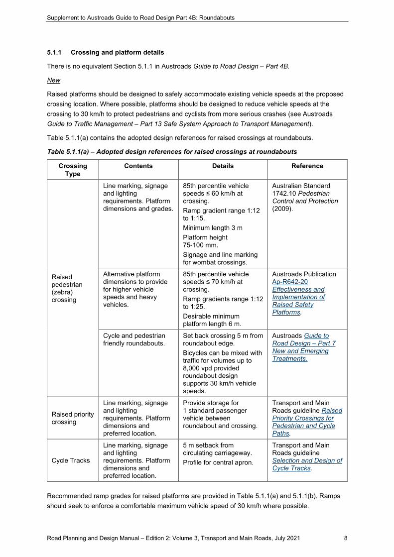
5.1.1 Crossing and platform details
There is no equivalent Section 5.1.1 in Austroads Guide to Road Design – Part 4B.
New
Raised platforms should be designed to safely accommodate existing vehicle speeds at the proposed crossing location. Where possible, platforms should be designed to reduce vehicle speeds at the crossing to 30 km/h to protect pedestrians and cyclists from more serious crashes (see Austroads Guide to Traffic Management – Part 13 Safe System Approach to Transport Management).
Table 5.1.1(a) contains the adopted design references for raised crossings at roundabouts.
Table 5.1.1(a) – Adopted design references for raised crossings at roundabouts
Crossing Type
Contents Details Reference
Raised pedestrian (zebra) crossing
Line marking, signage and lighting requirements. Platform dimensions and grades.
85th percentile vehicle speeds ≤ 60 km/h at crossing. Ramp gradient range 1:12 to 1:15. Minimum length 3 m Platform height 75-100 mm. Signage and line marking for wombat crossings.
Australian Standard 1742.10 Pedestrian Control and Protection (2009).
Alternative platform dimensions to provide for higher vehicle speeds and heavy vehicles.
85th percentile vehicle speeds ≤ 70 km/h at crossing. Ramp gradients range 1:12 to 1:25. Desirable minimum platform length 6 m.
Austroads Publication Ap-R642-20 Effectiveness and Implementation of Raised Safety Platforms.
Cycle and pedestrian friendly roundabouts.
Set back crossing 5 m from roundabout edge. Bicycles can be mixed with traffic for volumes up to 8,000 vpd provided roundabout design supports 30 km/h vehicle speeds.
Austroads Guide to Road Design – Part 7 New and Emerging Treatments.
Raised priority crossing
Line marking, signage and lighting requirements. Platform dimensions and preferred location.
Provide storage for 1 standard passenger vehicle between roundabout and crossing.
Transport and Main Roads guideline Raised Priority Crossings for Pedestrian and Cycle Paths.
Cycle Tracks
Line marking, signage and lighting requirements. Platform dimensions and preferred location.
5 m setback from circulating carriageway. Profile for central apron.
Transport and Main Roads guideline Selection and Design of Cycle Tracks.
Recommended ramp grades for raised platforms are provided in Table 5.1.1(a) and 5.1.1(b). Ramps should seek to enforce a comfortable maximum vehicle speed of 30 km/h where possible.

Supplement to Austroads Guide to Road Design Part 4B: Roundabouts
Road Planning and Design Manual – Edition 2: Volume 3, Transport and Main Roads, July 2021 9
Table 5.1.1(b) – Recommended ramp grades for platforms
85th Percentile Vehicle Speed at Crossing Location
Divided Carriageway Undivided Carriageway
Approach Ramp Grade
Comfortable max Speed
Approach / Departure Ramp Grade
Comfortable Max Speed (km/h)
50 km/h 1:15 (6.7%) 30 km/h 1:20 (5%) 40 km/h
60 km/h 1"20 (5%) 40 km/h 1:25 (4%) 50 km/h
70 km/h 1:25 (4%) 50 km/h 1:25 (4%) 50 km/h
Source: Austroads Publication Ap-R642-20 Effectiveness and Implementation of Raised Safety Platforms
Figure 5.1.1(a) – Typical Platform Profile for 50 km/h speed environment
Figure 5.1.1(b) and 5.1.1(c) show example layouts of pedestrian and cyclist crossings at roundabouts.

Supplement to Austroads Guide to Road Design Part 4B: Roundabouts
Road Planning and Design Manual – Edition 2: Volume 3, Transport and Main Roads, July 2021 10
Figure 5.1.1(b) - Concept for retrofit of raised wombat crossing to tangential roundabout

Supplement to Austroads Guide to Road Design Part 4B: Roundabouts
Road Planning and Design Manual – Edition 2: Volume 3, Transport and Main Roads, July 2021 11
Figure 5.1.1(c) – Wombat crossings at compact roundabout
Source: Mackay Regional Council
Refer to Section 2.5.3 design guidance for Roundabouts with raised platforms on approaches from Austroads Guide to Road Design – Part 7: New and Emerging Treatments for further guidance.
Supplement to Austroads Guide to Road Design Part 4B: Roundabouts
Road Planning and Design Manual – Edition 2: Volume 3, Transport and Main Roads, July 2021 12
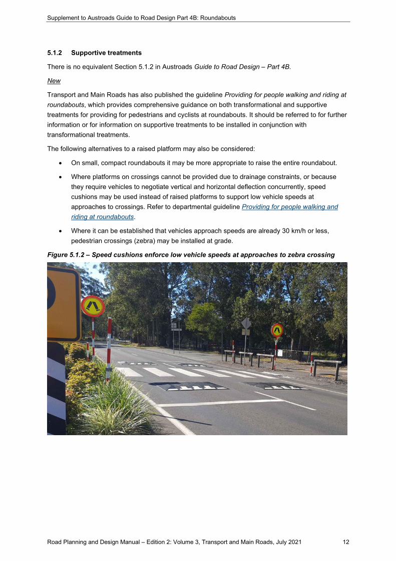
5.1.2 Supportive treatments
There is no equivalent Section 5.1.2 in Austroads Guide to Road Design – Part 4B.
New
Transport and Main Roads has also published the guideline Providing for people walking and riding at roundabouts, which provides comprehensive guidance on both transformational and supportive treatments for providing for pedestrians and cyclists at roundabouts. It should be referred to for further information or for information on supportive treatments to be installed in conjunction with transformational treatments.
The following alternatives to a raised platform may also be considered:
• On small, compact roundabouts it may be more appropriate to raise the entire roundabout.
• Where platforms on crossings cannot be provided due to drainage constraints, or because they require vehicles to negotiate vertical and horizontal deflection concurrently, speed cushions may be used instead of raised platforms to support low vehicle speeds at approaches to crossings. Refer to departmental guideline Providing for people walking and riding at roundabouts.
• Where it can be established that vehicles approach speeds are already 30 km/h or less, pedestrian crossings (zebra) may be installed at grade.
Figure 5.1.2 – Speed cushions enforce low vehicle speeds at approaches to zebra crossing

Supplement to Austroads Guide to Road Design Part 4B: Roundabouts
Road Planning and Design Manual – Edition 2: Volume 3, Transport and Main Roads, July 2021 13
5.2 Pedestrians
5.2.2 Designing roundabouts for pedestrians
Differences
The following paragraph is NOT accepted as a statement about the provision of crossing facilities and is to not be used in Queensland.
It is emphasised that with most roundabouts special crossing facilities will not be necessary. Generally, the installation of well-designed splitter islands of sufficient size to hold and protect pedestrians allows them to cross only one direction of traffic at a time. This should result in pedestrians being able to move more safely and freely around the intersection than was the case before the installation of the roundabout. On small roundabouts in local streets a cut-through of splitter islands at pavement level or a painted island may be appropriate. However, where pedestrian volumes are high, consideration should be given to the use of an alternative intersection treatment, particularly where there are schoolchildren or the elderly crossing.
Refer to TRUM Volume 1 Part 6 guidance for guidance on crossings can be provided on roundabouts.
5.3 Cyclists
5.3.5 Multi-lane roundabouts
New
Multi lane roundabouts present significant obstacles to safe movements of pedestrians and cyclists. These users must consider traffic approaching from multiple streams, in complex environments, to avoid crashes that are likely to result in serious injuries or fatalities. These intersections affect all pedestrians and cyclists but have a greater impact on more vulnerable users including children, older people and people with a disability or impairment.
If a roundabout treatment is warranted, a single lane roundabout, incorporating pedestrian and cyclist treatments (wombat crossings, raised priority crossings/cycle tracks) is the preferred intersection design.
Where multilane roundabouts are required for improving motorised vehicle safety and performance, appropriate facilities should be included to provide for all foreseeable pedestrian and cyclist movements. Appropriate facilities that eliminate pedestrian/cyclist/motorised vehicle conflicts may include grade separated crossings, where direct and comfortable connections to the pedestrian and cycling networks can be accommodated at the site.
If conflicts cannot be eliminated, then signalised crossings should be provided, or the geometry of the roundabout modified to support single vehicle lane approaches and provision of wombat crossings, raised priority crossing or cycle tracks connecting to pedestrian and cycling networks, on direct and comfortable desire lines. Where the site cannot accommodate these outcomes, alternative intersection treatments should be considered (signalised intersections for example).
5.3.6 Bicycle paths and shared paths at roundabouts
Difference
Figure 5.3 in AGRD Part 4B should be replaced with Figure 5.3.6.

Supplement to Austroads Guide to Road Design Part 4B: Roundabouts
Road Planning and Design Manual – Edition 2: Volume 3, Transport and Main Roads, July 2021 14
Figure 5.3.6 – Concept layout for crossings and underpass treatment on arterial roundabout
Source: Safe Systems Solutions PTY LTY
Designers should also refer to the guideline Providing for people walking and riding at roundabouts for guidance on supportive treatments for dual lane roundabouts.
6 Pavement markings and signing
6.1 Introduction
Additions
Wherever a reference to AS 1742.2 – Manual of Uniform Traffic Control Devices occurs, the Transport and Main Roads Manual of Uniform Traffic Control Devices must be used. Designers should also refer to Transport and Main Roads Traffic and Road Use Management Manual and particularly Volume 3, Part 2 Chapter 4.
6.2 Single-lane local street roundabout
Additions
Hazard marker signs should be used on both the outside curves and central island of the roundabout where visibility of the islands and kerbs may be unclear or where there is a history of vehicles not correctly negotiating the roundabout.
Supplement to Austroads Guide to Road Design Part 4B: Roundabouts
Road Planning and Design Manual – Edition 2: Volume 3, Transport and Main Roads, July 2021 15
6.3 Multi-lane arterial road roundabout
Additions
Where the approaches are line marked with non-standard lane usage, for example a double left turn or a double right turn, the line marking within the roundabout needs to be adapted. In particular, where an approach allows vehicles in two lanes to make a right turn, the pavement marking, between the double right turn entry and the next exit, must ensure that the centre lane is not used to exit by circulating vehicles. In this case spiral lane marking and alterations to the geometric design of the roundabout will be required.
Figure 6.2 of Austroads Guide to Road Design – Part 4B only depicts the directional signs and pavement markings at a roundabout. The title of this figure should therefore be “Figure 6.2: An example of directional signs and markings at a multi-lane arterial road roundabout”. For examples of the complete signs and markings for a multi-lane arterial road roundabout, refer to the Transport and Main Roads Manual of Uniform Traffic Control Devices and the Traffic and Road Use Management Manual.
7 Landscaping and street furniture
7.1 Introduction
Additions
In addition to the information in Austroads Guide to Road Design – Part 4B, designers should also refer to the following departmental publications with regards to lighting and landscaping at roundabouts:
• Road Planning and Design Manual Volume 6: Lighting
• Transport and Main Roads Road Landscape Manual.

Supplement to Austroads Guide to Road Design Part 4B: Roundabouts
Road Planning and Design Manual – Edition 2: Volume 3, Transport and Main Roads, July 2021 16
References
Transport and Main Roads publication references refer to the latest published document on the departmental website (www.tmr.qld.gov.au).
Additions
• Austroads (2015) Guide to Road Design - Part 4B: Roundabouts
• Transport and Main Roads ARNDT software program
• Transport and Main Roads Manual of Uniform Traffic Control Devices
• Transport and Main Roads Road Landscape Manual
• Transport and Main Roads guideline Selection and Design of Cycle Tracks
• Transport and Main Roads guideline Providing for People Walking and Riding at Roundabouts
• Transport and Main Roads Traffic and Road Use Management Manual.

Supplement to Austroads Guide to Road Design Part 4B: Roundabouts
Road Planning and Design Manual – Edition 2: Volume 3, Transport and Main Roads, July 2021 17
Appendix B – Roundabout study and program
Differences
The correct internet address for downloading the ARNDT program is “www.tmr.qld.gov.au”.

Supplement to Austroads Guide to Road Design Part 4B: Roundabouts
Road Planning and Design Manual – Edition 2: Volume 3, Transport and Main Roads, July 2021 18
Appendix D – Linemarking of multi-lane roundabouts
D.1 Introduction
Differences
Figure D1 is not accepted as an example of typical marking scheme at a multi-lane roundabout as it shows non-typical approach lane usage for through movements. The correct typical line marking scheme for a multi lane roundabout is depicted in Transport and Main Roads Traffic and Road Use Management Manual, Volume 3: Part 2 Chapter 4.