20
A e Authorized Manufacturer of GE Sports Lighting Design
| Date post: | 11-Mar-2018 |
| Category: |
Documents |
| Upload: | hoangduong |
| View: | 237 times |
| Download: | 7 times |
Ae Authorized Manufacturer of GE Sports Lighting Design
1 2
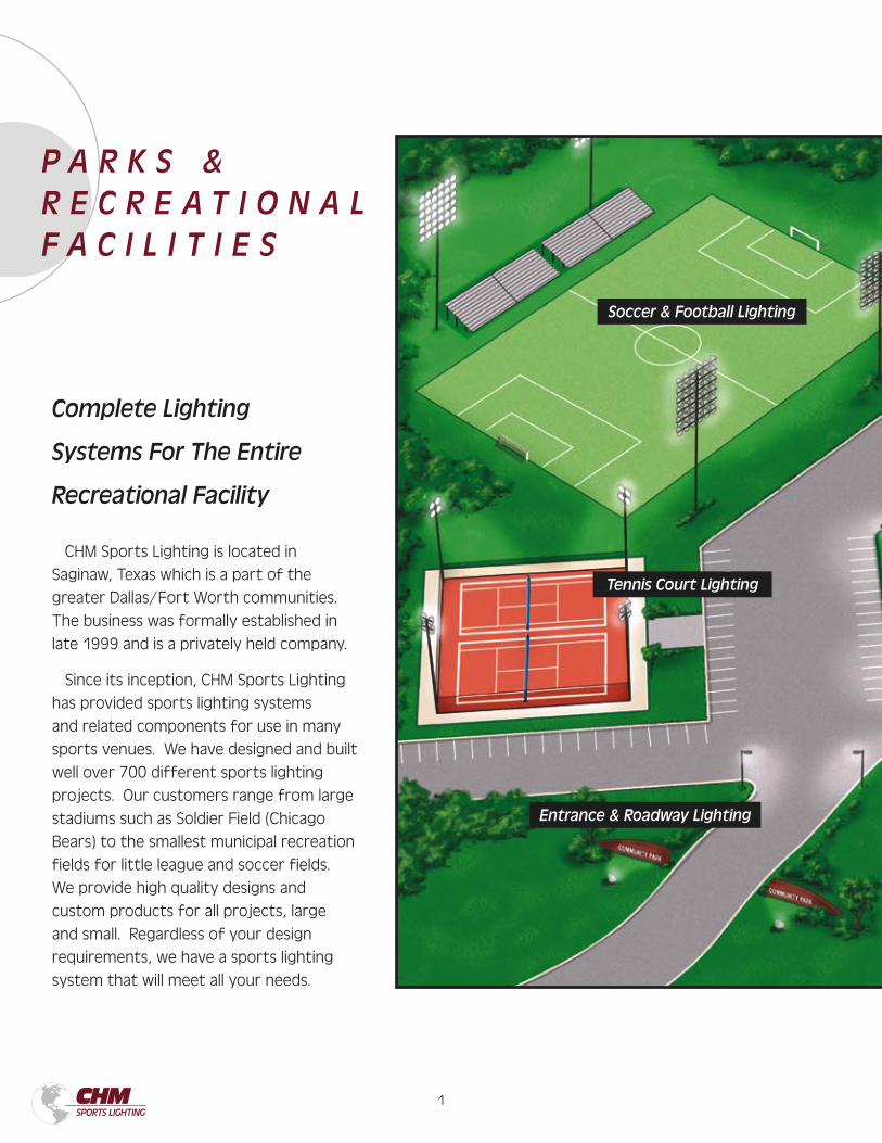
Entrance & Roadway Lighting
Tennis Court Lighting
Soccer & Football Lighting
Complete Lighting
Systems For The Entire
Recreational Facility
P A R K S & R E C R E A T I O N A L F A C I L I T I E S
CHM Sports Lighting is located in
Saginaw, Texas which is a part of the
greater Dallas/Fort Worth communities.
The business was formally established in
late 1999 and is a privately held company.
Since its inception, CHM Sports Lighting
has provided sports lighting systems
and related components for use in many
sports venues. We have designed and built
well over 700 different sports lighting
projects. Our customers range from large
stadiums such as Soldier Field (Chicago
Bears) to the smallest municipal recreation
fields for little league and soccer fields.
We provide high quality designs and
custom products for all projects, large
and small. Regardless of your design
requirements, we have a sports lighting
system that will meet all your needs.
1 2
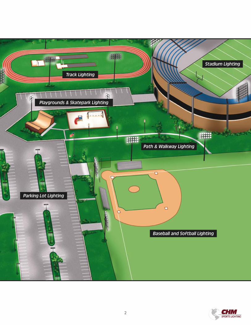
Baseball and Softball Lighting
Stadium Lighting
Playgrounds & Skatepark Lighting
Track Lighting
Parking Lot Lighting
Path & Walkway Lighting
3 4
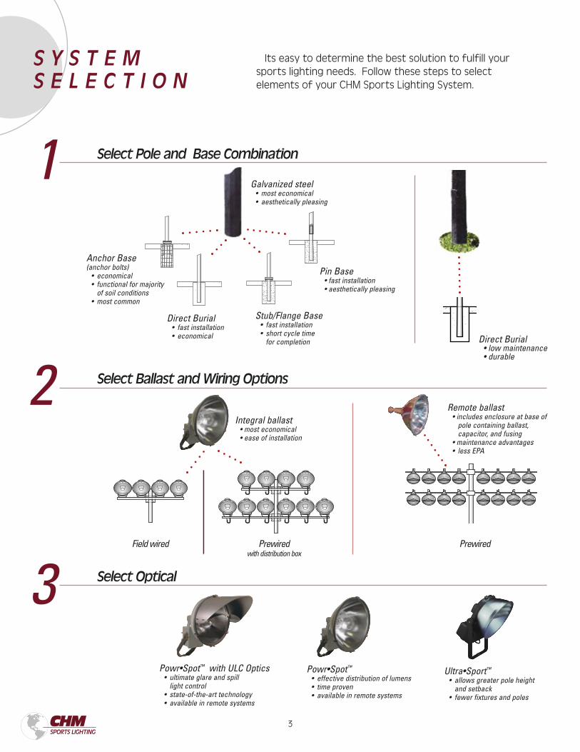
Its easy to determine the best solution to fulfill your sports lighting needs. Follow these steps to select elements of your CHM Sports Lighting System.
Stub/Flange Base • fast installation • short cycle time for completion
1 Select Pole and Base Combination
2 Select Ballast and Wiring Options
Pin Base • fast installation • aesthetically pleasing
Direct Burial • low maintenance • durable
3 Select Optical
Integral ballast • most economical • ease of installation
Remote ballast • includes enclosure at base of pole containing ballast, capacitor, and fusing • maintenance advantages • less EPA
Powr•Spot™ with ULC Optics • ultimate glare and spill light control • state-of-the-art technology • available in remote systems
Galvanized steel • most economical • aesthetically pleasing
Anchor Base (anchor bolts) • economical • functional for majority of soil conditions • most common
Direct Burial • fast installation • economical
Powr•Spot™
• effective distribution of lumens • time proven • available in remote systems
Ultra•Sport™
• allows greater pole height and setback • fewer fixtures and poles
Field wired Prewiredwith distribution box
Prewired
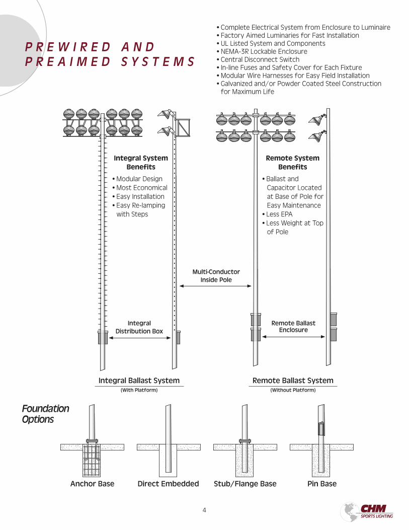
S Y S T E M S E L E C T I O N
3 4
Remote Ballast System(Without Platform)
Remote Ballast Enclosure
Integral Ballast System(With Platform)
Integral Distribution Box
Pin BaseAnchor Base Stub/Flange BaseDirect Embedded
Integral System Benefits
• Modular Design• Most Economical• Easy Installation• Easy Re-lamping with Steps
Remote System Benefits
• Ballast and Capacitor Located at Base of Pole for Easy Maintenance
• Less EPA• Less Weight at Top
of Pole
• Complete Electrical System from Enclosure to Luminaire• Factory Aimed Luminaries for Fast Installation• UL Listed System and Components• NEMA-3R Lockable Enclosure• Central Disconnect Switch• In-line Fuses and Safety Cover for Each Fixture• Modular Wire Harnesses for Easy Field Installation• Galvanized and/or Powder Coated Steel Construction for Maximum Life
P R E W I R E D A N DP R E A I M E D S Y S T E M S
Multi-ConductorInside Pole
FoundationOptions
5 6
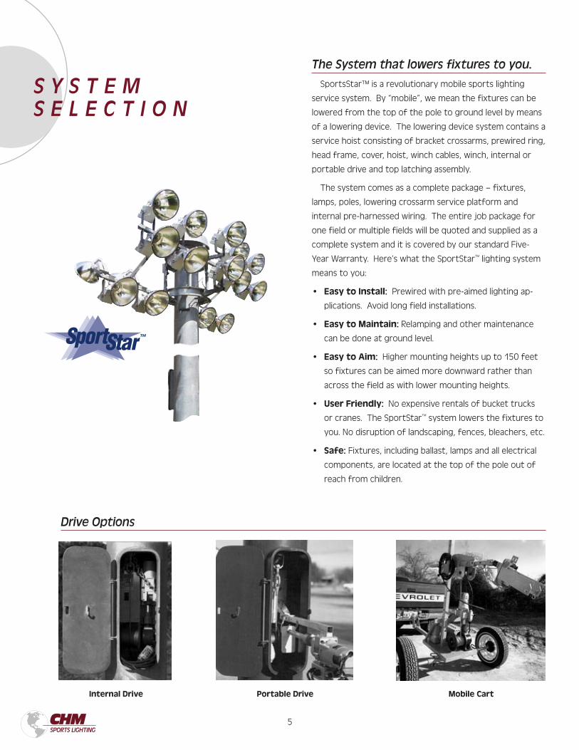
The System that lowers fixtures to you.
SportsStar™ is a revolutionary mobile sports lighting
service system. By “mobile”, we mean the fixtures can be
lowered from the top of the pole to ground level by means
of a lowering device. The lowering device system contains a
service hoist consisting of bracket crossarms, prewired ring,
head frame, cover, hoist, winch cables, winch, internal or
portable drive and top latching assembly.
The system comes as a complete package – fixtures,
lamps, poles, lowering crossarm service platform and
internal pre-harnessed wiring. The entire job package for
one field or multiple fields will be quoted and supplied as a
complete system and it is covered by our standard Five-
Year Warranty. Here’s what the SportStar™ lighting system
means to you:
• Easy to Install: Prewired with pre-aimed lighting ap-
plications. Avoid long field installations.
• Easy to Maintain: Relamping and other maintenance
can be done at ground level.
• Easy to Aim: Higher mounting heights up to 150 feet
so fixtures can be aimed more downward rather than
across the field as with lower mounting heights.
• User Friendly: No expensive rentals of bucket trucks
or cranes. The SportStar™ system lowers the fixtures to
you. No disruption of landscaping, fences, bleachers, etc.
• Safe: Fixtures, including ballast, lamps and all electrical
components, are located at the top of the pole out of
reach from children.
Internal Drive Portable Drive Mobile Cart
Drive Options
S Y S T E M S E L E C T I O N
5 6
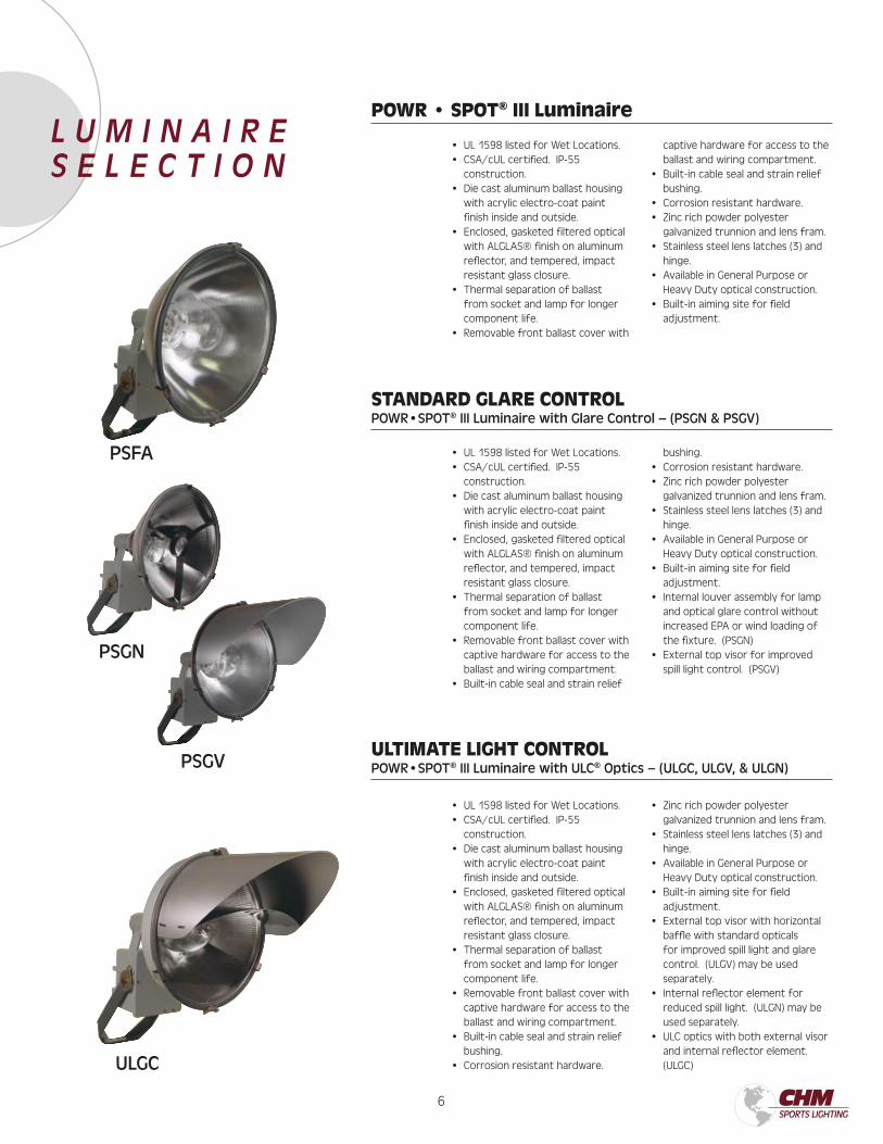
POWR • SPOT® III Luminaire
STANDARD GLARE CONTROLPOWR•SPOT® III Luminaire with Glare Control – (PSGN & PSGV)
ULTIMATE LIGHT CONTROLPOWR•SPOT® III Luminaire with ULC® Optics – (ULGC, ULGV, & ULGN)
• UL 1598 listed for Wet Locations.• CSA/cUL certified. IP-55
construction.• Die cast aluminum ballast housing
with acrylic electro-coat paint finish inside and outside.
• Enclosed, gasketed filtered optical with ALGLAS® finish on aluminum reflector, and tempered, impact resistant glass closure.
• Thermal separation of ballast from socket and lamp for longer component life.
• Removable front ballast cover with
captive hardware for access to the ballast and wiring compartment.
• Built-in cable seal and strain relief bushing.
• Corrosion resistant hardware.• Zinc rich powder polyester
galvanized trunnion and lens fram.• Stainless steel lens latches (3) and
hinge.• Available in General Purpose or
Heavy Duty optical construction.• Built-in aiming site for field
adjustment.
• UL 1598 listed for Wet Locations.• CSA/cUL certified. IP-55
construction.• Die cast aluminum ballast housing
with acrylic electro-coat paint finish inside and outside.
• Enclosed, gasketed filtered optical with ALGLAS® finish on aluminum reflector, and tempered, impact resistant glass closure.
• Thermal separation of ballast from socket and lamp for longer component life.
• Removable front ballast cover with captive hardware for access to the ballast and wiring compartment.
• Built-in cable seal and strain relief
bushing.• Corrosion resistant hardware.• Zinc rich powder polyester
galvanized trunnion and lens fram.• Stainless steel lens latches (3) and
hinge.• Available in General Purpose or
Heavy Duty optical construction.• Built-in aiming site for field
adjustment.• Internal louver assembly for lamp
and optical glare control without increased EPA or wind loading of the fixture. (PSGN)
• External top visor for improved spill light control. (PSGV)
• UL 1598 listed for Wet Locations.• CSA/cUL certified. IP-55
construction.• Die cast aluminum ballast housing
with acrylic electro-coat paint finish inside and outside.
• Enclosed, gasketed filtered optical with ALGLAS® finish on aluminum reflector, and tempered, impact resistant glass closure.
• Thermal separation of ballast from socket and lamp for longer component life.
• Removable front ballast cover with captive hardware for access to the ballast and wiring compartment.
• Built-in cable seal and strain relief bushing.
• Corrosion resistant hardware.
• Zinc rich powder polyester galvanized trunnion and lens fram.
• Stainless steel lens latches (3) and hinge.
• Available in General Purpose or Heavy Duty optical construction.
• Built-in aiming site for field adjustment.
• External top visor with horizontal baffle with standard opticals for improved spill light and glare control. (ULGV) may be used separately.
• Internal reflector element for reduced spill light. (ULGN) may be used separately.
• ULC optics with both external visor and internal reflector element. (ULGC)
PSGN
PSGV
L U M I N A I R E S E L E C T I O N
PSFA
ULGC
7 8
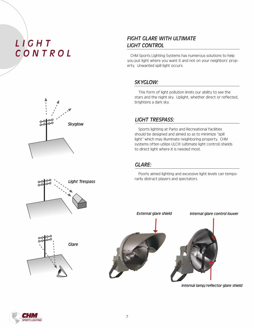
LIGHT TRESPASS:
SKYGLOW:
GLARE:
FIGHT GLARE WITH ULTIMATE LIGHT CONTROL
CHM Sports Lighting Systems has numerous solutions to help you put light where you want it and not on your neighbors’ prop-erty. Unwanted spill light occurs:
This form of light pollution limits our ability to see the stars and the night sky. Uplight, whether direct or reflected, brightens a dark sky.
Sports lighting at Parks and Recreational facilities should be designed and aimed so as to minimize “spill light” which may illuminate neighboring property. CHM systems often utilize ULC® (ultimate light control) shields to direct light where it is needed most.
Poorly aimed lighting and excessive light levels can tempo-rarily distract players and spectators.
External glare shield Internal glare control louver
Internal lamp/reflector glare shield
Skyglow
Light Trespass
Glare
L I G H T C O N T R O L
7 8
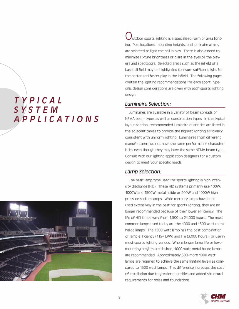
Outdoor sports lighting is a specialized form of area light-
ing. Pole locations, mounting heights, and luminaire aiming
are selected to light the ball in play. There is also a need to
minimize fixture brightness or glare in the eyes of the play-
ers and spectators. Selected areas such as the infield of a
baseball field may be highlighted to insure sufficient light for
the batter and faster play in the infield. The following pages
contain the lighting recommendations for each sport. Spe-
cific design considerations are given with each sports lighting
design.
Luminaire Selection:
Luminaires are available in a variety of beam spreads or
NEMA beam types as well as construction types. In the typical
layout section, recommended luminaire quantities are listed in
the adjacent tables to provide the highest lighting efficiency
consistent with uniform lighting. Luminaires from different
manufacturers do not have the same performance character-
istics even though they may have the same NEMA beam type.
Consult with our lighting application designers for a custom
design to meet your specific needs.
Lamp Selection:
The basic lamp type used for sports lighting is high inten-
sity discharge (HID). These HID systems primarily use 400W,
1000W and 1500W metal halide or 400W and 1000W high
pressure sodium lamps. While mercury lamps have been
used extensively in the past for sports lighting, they are no
longer recommended because of their lower efficiency. The
life of HID lamps vary from 1,500 to 24,000 hours. The most
common lamps used today are the 1000 and 1500 watt metal
halide lamps. The 1500 watt lamp has the best combination
of lamp efficiency (115+ LPW) and life (3,000 hours) for use in
most sports lighting venues. Where longer lamp life or lower
mounting heights are desired, 1000 watt metal halide lamps
are recommended. Approximately 50% more 1000 watt
lamps are required to achieve the same lighting levels as com-
pared to 1500 watt lamps. This difference increases the cost
of installation due to greater quantities and added structural
requirements for poles and foundations.
T Y P I C A LS Y S T E MA P P L I C A T I O N S
9 10
Warm Up & Restrike Time:
HID lamps require 3-7 minutes to warm up if a momentary
power interruption occurs. These lamps require the same
amount of time to return to full luminance. Some form of in-
stant-on lighting, usually one or two incandescent luminaries per
pole, is recommended to provide lighting during the 1-15 minute
restrike time. In addition, the incandescent (quartz) type fix-
tures should be used for emergency lighting of the fields when
required. HID fixtures with optional “hot lamp restrike” capability
are available. This option is for “hot restrike” only and does not
provide “instant light” when the fixtures are cold started.
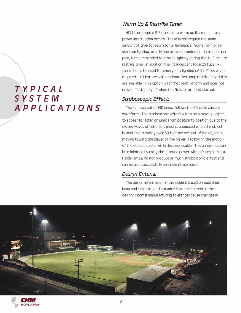
Stroboscopic Effect:
The light output of HID lamps follows the 60-cycle current
waveform. The stroboscopic effect will cause a moving object
to appear to flicker or jump from position to position due to the
cycling waves of light. It is most pronounced when the object
is small and traveling over 50 feet per second. If the object is
moving toward the player or the player is following the motion
of the object, strobe will be less noticeable. This annoyance can
be minimized by using three-phase power with HID lamps. Metal
Halide lamps, do not produce as much stroboscopic effect and
can be used successfully on single-phase power.
Design Criteria:
The design information in this guide is based on published
lamp and luminaire performance that are inherent in their
design. Normal manufacturing tolerances cause changes in
T Y P I C A LS Y S T E MA P P L I C A T I O N S
9 10
a lamp’s electrical characteristics and lumen output. Light
changes in reflector finish and lamp position can alter the
photometric distribution of the luminaire. Changes in the
ballast and line voltage will also alter the output of the lamp.
As a result of these variations average illumination levels can
be expected to vary with 10% of the design value. Individual
point-by-point footcandle values can vary more than this,
especially when only a few luminaires are involved, resulting in
little overlap between luminaires.
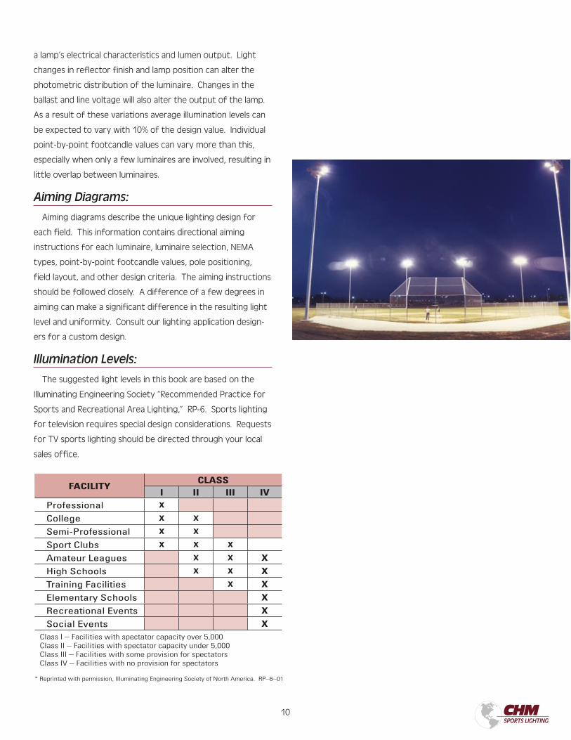
Aiming Diagrams:
Aiming diagrams describe the unique lighting design for
each field. This information contains directional aiming
instructions for each luminaire, luminaire selection, NEMA
types, point-by-point footcandle values, pole positioning,
field layout, and other design criteria. The aiming instructions
should be followed closely. A difference of a few degrees in
aiming can make a significant difference in the resulting light
level and uniformity. Consult our lighting application design-
ers for a custom design.
Illumination Levels:
The suggested light levels in this book are based on the
Illuminating Engineering Society “Recommended Practice for
Sports and Recreational Area Lighting,” RP-6. Sports lighting
for television requires special design considerations. Requests
for TV sports lighting should be directed through your local
sales office.
FACILITYCLASS
I II III IVProfessional X
College X X
Semi-Professional X X
Sport Clubs X X X
Amateur Leagues X X X
High Schools X X X
Training Facilities X X
Elementary Schools X
Recreational Events X
Social Events XClass I – Facilities with spectator capacity over 5,000Class II – Facilities with spectator capacity under 5,000Class III – Facilities with some provision for spectatorsClass IV – Facilities with no provision for spectators
* Reprinted with permission, Illuminating Engineering Society of North America. RP–6–01
11 12
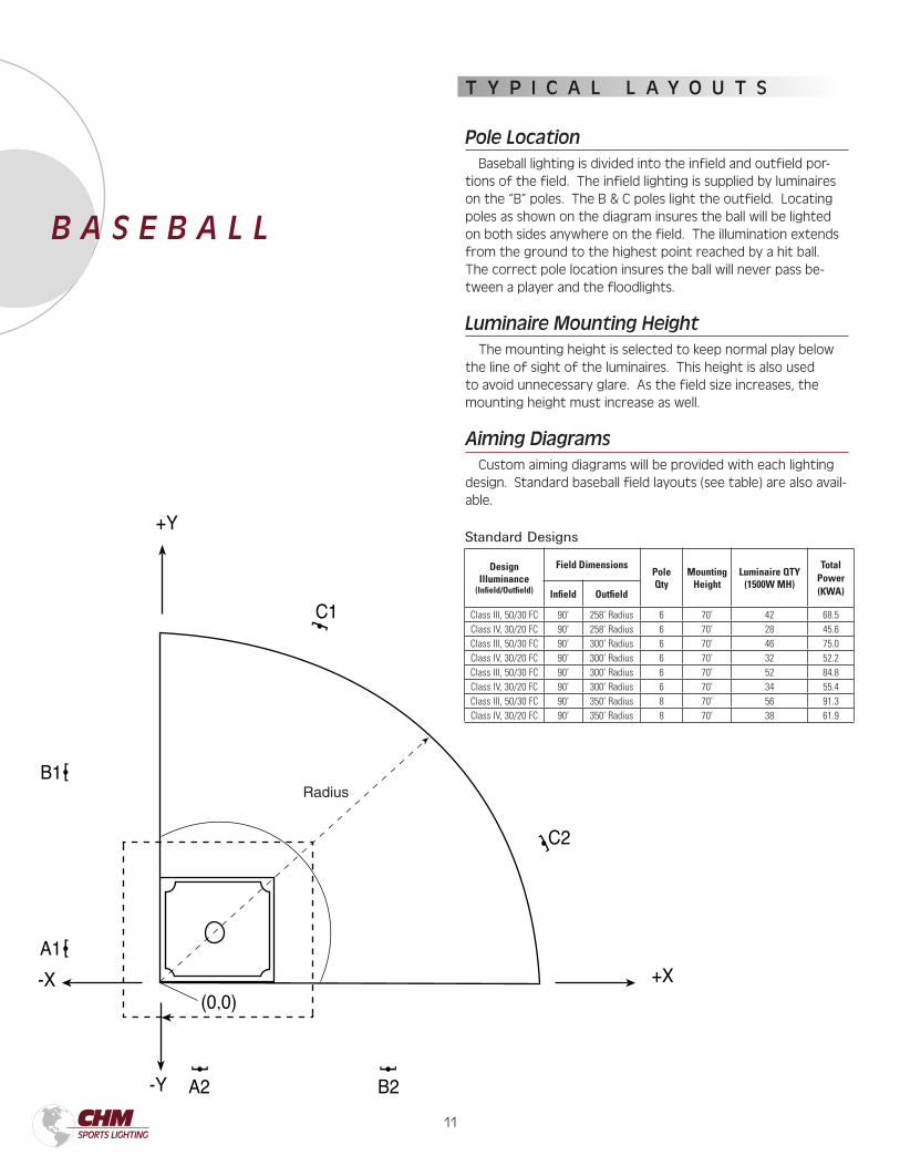
Design Illuminance
(Infield/Outfield)
Field DimensionsPoleQty
MountingHeight
Luminaire QTY(1500W MH)
TotalPower(KWA)Infield Outfield
Class III, 50/30 FC 90’ 258’ Radius 6 70’ 42 68.5Class IV, 30/20 FC 90’ 258’ Radius 6 70’ 28 45.6Class III, 50/30 FC 90’ 300’ Radius 6 70’ 46 75.0Class IV, 30/20 FC 90’ 300’ Radius 6 70’ 32 52.2Class III, 50/30 FC 90’ 300’ Radius 6 70’ 52 84.8Class IV, 30/20 FC 90’ 300’ Radius 6 70’ 34 55.4Class III, 50/30 FC 90’ 350’ Radius 8 70’ 56 91.3Class IV, 30/20 FC 90’ 350’ Radius 8 70’ 38 61.9
B A S E B A L L
T Y P I C A L L A Y O U T S
Pole Location Baseball lighting is divided into the infield and outfield por-tions of the field. The infield lighting is supplied by luminaires on the “B” poles. The B & C poles light the outfield. Locating poles as shown on the diagram insures the ball will be lighted on both sides anywhere on the field. The illumination extends from the ground to the highest point reached by a hit ball. The correct pole location insures the ball will never pass be-tween a player and the floodlights.
Luminaire Mounting Height The mounting height is selected to keep normal play below the line of sight of the luminaires. This height is also used to avoid unnecessary glare. As the field size increases, the mounting height must increase as well.
Aiming Diagrams Custom aiming diagrams will be provided with each lighting design. Standard baseball field layouts (see table) are also avail-able.
Standard Designs
Radius
11 12
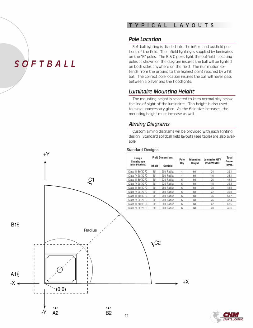
S O F T B A L L
T Y P I C A L L A Y O U T S
Pole Location Softball lighting is divided into the infield and outfield por-tions of the field. The infield lighting is supplied by luminaires on the “B” poles. The B & C poles light the outfield. Locating poles as shown on the diagram insures the ball will be lighted on both sides anywhere on the field. The illumination ex-tends from the ground to the highest point reached by a hit ball. The correct pole location insures the ball will never pass between a player and the floodlights.
Luminaire Mounting Height The mounting height is selected to keep normal play below the line of sight of the luminaires. This height is also used to avoid unnecessary glare. As the field size increases, the mounting height must increase as well.
Aiming Diagrams Custom aiming diagrams will be provided with each lighting design. Standard softball field layouts (see table) are also avail-able.
Design Illuminance
(Infield/Outfield)
Field DimensionsPoleQty
MountingHeight
Luminaire QTY(1500W MH)
TotalPower(KWA)Infield Outfield
Class III, 50/30 FC 60’ 200’ Radius 4 60’ 24 39.1Class IV, 30/20 FC 60’ 200’ Radius 4 60’ 16 26.1Class III, 50/30 FC 60’ 225’ Radius 6 60’ 26 42.4Class IV, 30/20 FC 60’ 225’ Radius 6 60’ 18 29.3Class III, 50/30 FC 60’ 250’ Radius 6 60’ 30 48.9Class IV, 30/20 FC 60’ 250’ Radius 6 60’ 22 35.9Class III, 50/30 FC 60’ 280’ Radius 6 60’ 36 58.7Class IV, 30/20 FC 60’ 280’ Radius 6 60’ 26 42.4Class III, 50/30 FC 60’ 300’ Radius 6 60’ 42 68.5Class IV, 30/20 FC 60’ 300’ Radius 6 60’ 28 45.6
Standard Designs
Radius
13 14
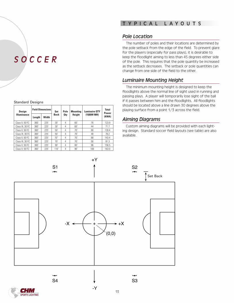
T Y P I C A L L A Y O U T S
Pole Location The number of poles and their locations are determined by the pole setback from the edge of the field. To prevent glare for the players (especially for pass plays), it is desirable to keep the floodlight aiming to less than 45 degrees either side of the pole. This requires that the pole quantity be increased as the setback decreases. The setback or pole quantities can change from one side of the field to the other.
Luminaire Mounting Height The minimum mounting height is designed to keep the floodlights above the normal line of sight used in running and passing plays. A player will temporarily lose sight of the ball if it passes between him and the floodlights. All floodlights should be located above a line drawn 30 degrees above the playing surface from a point 1/3 across the field.
Aiming Diagrams Custom aiming diagrams will be provided with each light-ing design. Standard soccer field layouts (see table) are also available.
S O C C E R
Design Illuminance
Field DimensionsSet
BackPoleQty
MountingHeight
Luminaire QTY(1500W MH)
TotalPower(KWA)Length Width
Class II, 50 FC 360’ 225’ 30’ 4 60’ 76 123.9Class III, 30 FC 360’ 225’ 30’ 4 60’ 44 71.7Class II, 50 FC 360’ 225’ 50’ 4 70’ 80 130.4Class III, 30 FC 360’ 225’ 50’ 4 70’ 48 78.2Class II, 50 FC 360’ 225’ 70” 4 70’ 88 143.4Class III, 30 FC 360’ 225’ 70’ 4 70’ 56 91.3Class II, 50 FC 360’ 225’ 90’ 4 80’ 96 156.5Class II, 50 FC 360’ 225’ 110’ 4 90’ 100 163.0
Set Back
Standard Designs
13 14
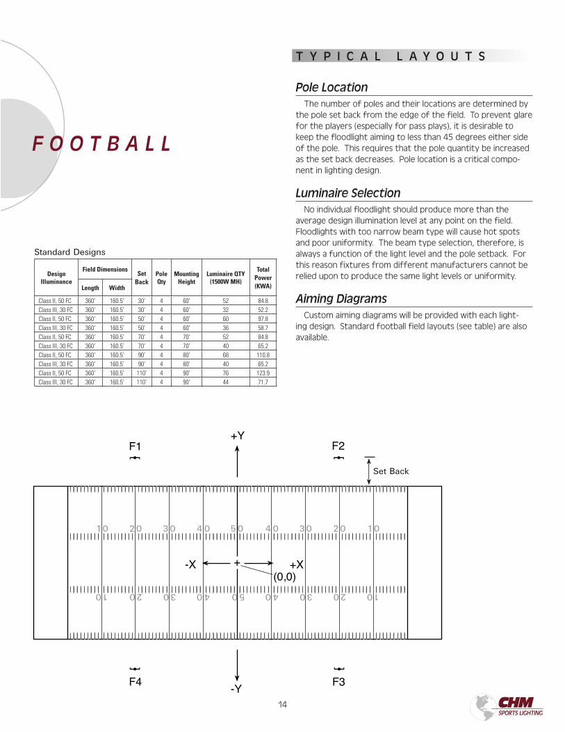
T Y P I C A L L A Y O U T S
Pole Location The number of poles and their locations are determined by the pole set back from the edge of the field. To prevent glare for the players (especially for pass plays), it is desirable to keep the floodlight aiming to less than 45 degrees either side of the pole. This requires that the pole quantity be increased as the set back decreases. Pole location is a critical compo-nent in lighting design.
Luminaire Selection No individual floodlight should produce more than the average design illumination level at any point on the field. Floodlights with too narrow beam type will cause hot spots and poor uniformity. The beam type selection, therefore, is always a function of the light level and the pole setback. For this reason fixtures from different manufacturers cannot be relied upon to produce the same light levels or uniformity.
Aiming Diagrams Custom aiming diagrams will be provided with each light-ing design. Standard football field layouts (see table) are also available.
F O O T B A L L
Design Illuminance
Field DimensionsSet
BackPoleQty
MountingHeight
Luminaire QTY(1500W MH)
TotalPower(KWA)Length Width
Class II, 50 FC 360’ 160.5’ 30’ 4 60’ 52 84.8Class III, 30 FC 360’ 160.5’ 30’ 4 60’ 32 52.2Class II, 50 FC 360’ 160.5’ 50’ 4 60’ 60 97.8Class III, 30 FC 360’ 160.5’ 50’ 4 60’ 36 58.7Class II, 50 FC 360’ 160.5’ 70’ 4 70’ 52 84.8Class III, 30 FC 360’ 160.5’ 70’ 4 70’ 40 65.2Class II, 50 FC 360’ 160.5’ 90’ 4 80’ 68 110.8Class III, 30 FC 360’ 160.5’ 90’ 4 80’ 40 65.2Class II, 50 FC 360’ 160.5’ 110’ 4 90’ 76 123.9Class III, 30 FC 360’ 160.5’ 110’ 4 90’ 44 71.7
10 20 30 4 0 5 0 4 0 30 20 10
102030405040302010
Set Back
Standard Designs
15 16
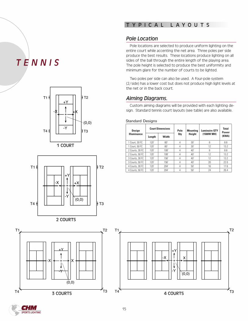
T Y P I C A L L A Y O U T S
Pole Location Pole locations are selected to produce uniform lighting on the entire court while accenting the net area. Three poles per side produce the best results. These locations produce lighting on all sides of the ball through the entire length of the playing area. The pole height is selected to produce the best uniformity and minimum glare for the number of courts to be lighted.
Two poles per side can also be used. A four-pole system (2/side) has a lower cost but does not produce high light levels at the net or in the back court.
Aiming Diagrams. Custom aiming diagrams will be provided with each lighting de-sign. Standard tennis court layouts (see table) are also available.
T E N N I S
Design Illuminance
Court DimensionsPoleQty
MountingHeight
Luminaire QTY(1500W MH)
TotalPower(KWA)Length Width
1 Court, 30 FC 120’ 60’ 4 30’ 8 8.81 Court, 50 FC 120’ 60’ 4 30’ 12 13.22 Courts, 30 FC 120’ 108’ 4 40’ 8 8.82 Courts, 50 FC 120’ 108’ 4 40’ 12 13.23 Courts, 30 FC 120’ 156’ 4 40’ 12 13.23 Courts, 50 FC 120’ 156’ 4 40’ 20 22.04 Courts, 30 FC 120’ 204’ 4 50’ 16 17.64 Courts, 50 FC 120’ 204’ 4 50’ 24 26.4
Standard Designs
4 COURTS
1 COURT
2 COURTS
3 COURTS
15 16
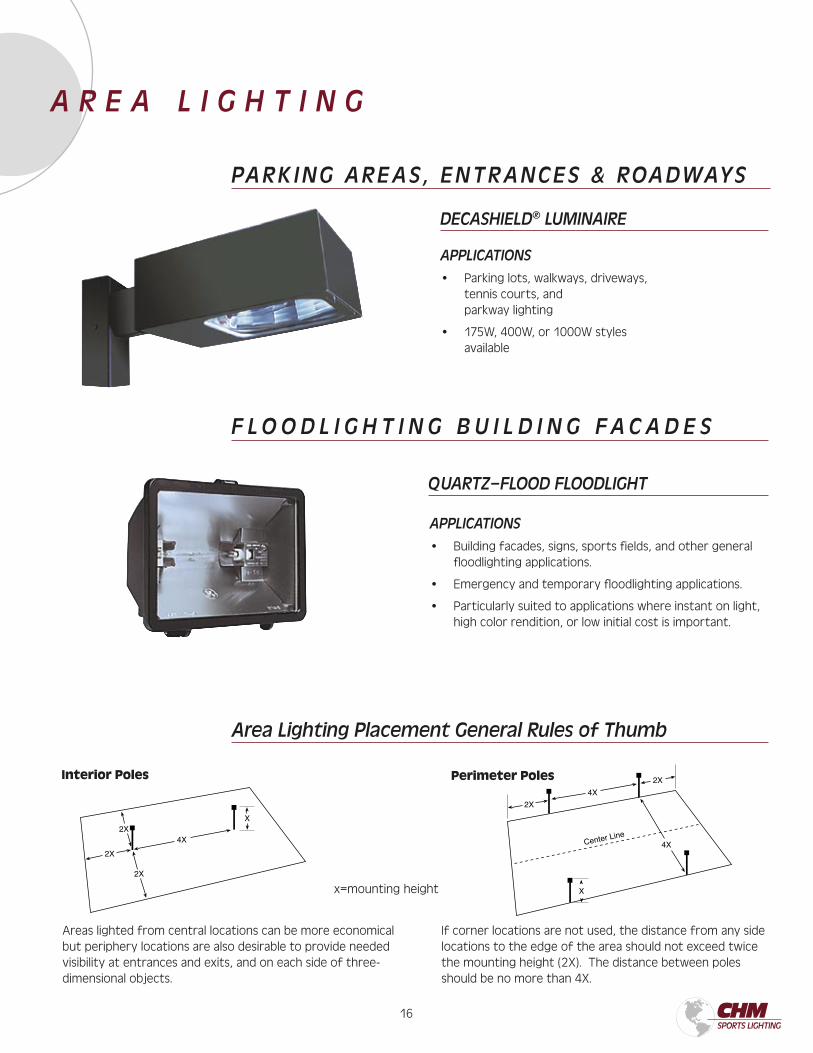
PARK ING AREAS , ENTRANCES & ROADWAYS
DECASHIELD® LUMINAIRE
APPLICATIONS
• Parking lots, walkways, driveways, tennis courts, and parkway lighting
• 175W, 400W, or 1000W styles available
x=mounting height
Area Lighting Placement General Rules of Thumb
Interior Poles Perimeter Poles
Areas lighted from central locations can be more economical but periphery locations are also desirable to provide needed visibility at entrances and exits, and on each side of three-dimensional objects.
If corner locations are not used, the distance from any side locations to the edge of the area should not exceed twice the mounting height (2X). The distance between poles should be no more than 4X.
F L O O D L I G H T I N G B U I L D I N G F A C A D E S
APPLICATIONS
• Building facades, signs, sports fields, and other general floodlighting applications.
• Emergency and temporary floodlighting applications.
• Particularly suited to applications where instant on light, high color rendition, or low initial cost is important.
QUARTZ–FLOOD FLOODLIGHT
A R E A L I G H T I N G
17 18
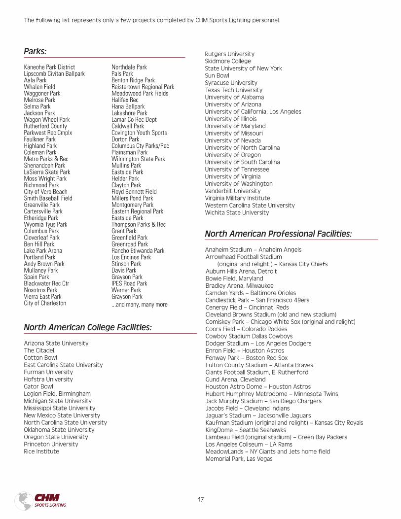
North American College Facilities:
Arizona State UniversityThe CitadelCotton BowlEast Carolina State UniversityFurman UniversityHofstra UniversityGator BowlLegion Field, BirminghamMichigan State UniversityMississippi State UniversityNew Mexico State UniversityNorth Carolina State UniversityOklahoma State UniversityOregon State UniversityPrinceton UniversityRice Institute
Rutgers UniversitySkidmore CollegeState University of New YorkSun BowlSyracuse UniversityTexas Tech UniversityUniversity of AlabamaUniversity of ArizonaUniversity of California, Los AngelesUniversity of IllinoisUniversity of MarylandUniversity of MissouriUniversity of NevadaUniversity of North CarolinaUniversity of OregonUniversity of South CarolinaUniversity of TennesseeUniversity of VirginiaUniversity of WashingtonVanderbilt UniversityVirginia Military InstituteWestern Carolina State UniversityWichita State University
North American Professional Facilities:
Anaheim Stadium – Anaheim AngelsArrowhead Football Stadium
(original and relight ) – Kansas City ChiefsAuburn Hills Arena, DetroitBowie Field, MarylandBradley Arena, MilwaukeeCamden Yards – Baltimore OriolesCandlestick Park – San Francisco 49ersCenergy Field – Cincinnati RedsCleveland Browns Stadium (old and new stadium)Comiskey Park – Chicago White Sox (original and relight)Coors Field – Colorado RockiesCowboy Stadium Dallas CowboysDodger Stadium – Los Angeles DodgersEnron Field – Houston AstrosFenway Park – Boston Red SoxFulton County Stadium – Atlanta BravesGiants Football Stadium, E. RutherfordGund Arena, ClevelandHouston Astro Dome – Houston AstrosHubert Humphrey Metrodome – Minnesota TwinsJack Murphy Stadium – San Diego ChargersJacobs Field – Cleveland IndiansJaguar’s Stadium – Jacksonville JaguarsKaufman Stadium (original and relight) – Kansas City RoyalsKingDome – Seattle SeahawksLambeau Field (original stadium) – Green Bay PackersLos Angeles Coliseum – LA RamsMeadowLands – NY Giants and Jets home fieldMemorial Park, Las Vegas
Kaneohe Park DistrictLipscomb Civitan BallparkAala ParkWhalen FieldWaggoner ParkMelrose ParkSelma ParkJackson ParkWagon Wheel ParkRutherford County Parkwest Rec CmplxFaulkner ParkHighland ParkColeman ParkMetro Parks & RecShenandoah ParkLaSierra Skate ParkMoss Wright ParkRichmond ParkCity of Vero BeachSmith Baseball FieldGreenville ParkCartersville ParkEtheridge ParkWyomia Tyus ParkColumbus ParkCloverleaf ParkBen Hill ParkLake Park ArenaPortland ParkAndy Brown ParkMullaney ParkSpain ParkBlackwater Rec CtrNosotros ParkVierra East ParkCity of Charleston
Northdale ParkPals ParkBenton Ridge ParkReistertown Regional ParkMeadowood Park FieldsHalifax RecHana BallparkLakeshore ParkLamar Co Rec DeptCaldwell ParkCovington Youth SportsDorton ParkColumbus Cty Parks/RecPlainsman ParkWilmington State ParkMullins ParkEastside ParkHelder ParkClayton ParkFloyd Bennett FieldMillers Pond ParkMontgomery ParkEastern Regional ParkEastside ParkThompson Parks & RecGrant ParkGreenfield ParkGreenroad ParkRancho Etiwanda ParkLos Encinos ParkStinson ParkDavis ParkGrayson ParkIPES Road ParkWarner Park Grayson Park...and many, many more
Parks:
The following list represents only a few projects completed by CHM Sports Lighting personnel.
17 18
Miami ArenaMile High Stadium – Denver Broncos
(original and new stadium)Molson Centre, MontrealOakland Coliseum – Oakland RaidersPAC BELL Park – San Francisco GiantsPNC Ballpark – Pittsburgh PiratesPaul Brown Stadium – Cincinnati BengalsQual Comm Park – San Diego padresRFK Stadium (original stadium) – Washington RedskinsRalph Wilson Stadium – Buffalo Bills (original and relight)Richfield Coliseum, ClevelandSafeco Field – Seattle MarinersSam Houston Track, HoustonSilver Dome – Detroit LionsSt. Petersburg Dome StadiumSun Devil’s Stadium – Phoenix CardinalsTampa Bay Stadium (original stadium –
Tampa Bay BuccaneersTiger Stadium – Detroit TigersTropicana Dome – Devil RaysPhiladelphia Veteran’s Stadium –
Philadelphia Eagles and PhilliesWrigley Field – Chicago Cubs
19
www.chmsportslighting.com700 McLeroy Blvd., Saginaw, TX 76179
682-286-0046 (Phone) 682-286-0086 (Fax)


