Authors : G. H. Jang, J. H. Park and J. H. Chang IEE Proceedings – Electric Power Applications, Vol. 149, No. 2, March 2002 Department of Electrical Engineering Southern Taiwan University Position Detection and Start-Up Position Detection and Start-Up Algorithm of a Rotor in a Algorithm of a Rotor in a Sensorless BLDC Motor Utilizing Sensorless BLDC Motor Utilizing Inductance Variation Inductance Variation Student : Sergiu Berinde M972B206
Transcript
Authors : G. H. Jang, J. H. Park and J. H. Chang
IEE Proceedings – Electric Power Applications, Vol. 149, No. 2, March 2002
Department of Electrical Engineering
Southern Taiwan University
Position Detection and Start-Up Algorithm of Position Detection and Start-Up Algorithm of a Rotor in a Sensorless BLDC Motor a Rotor in a Sensorless BLDC Motor
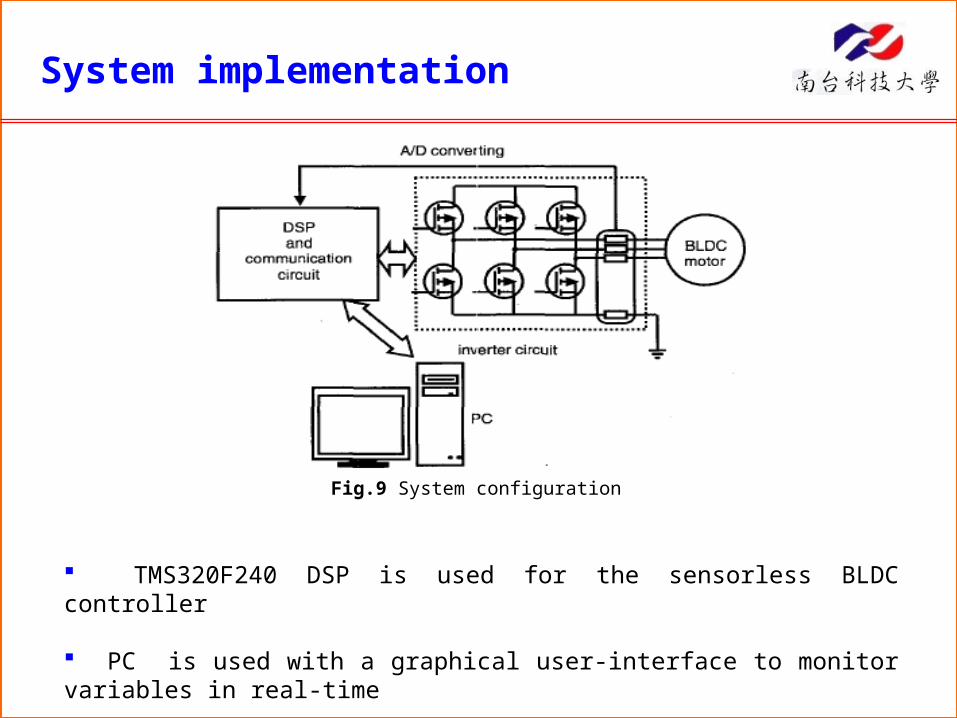
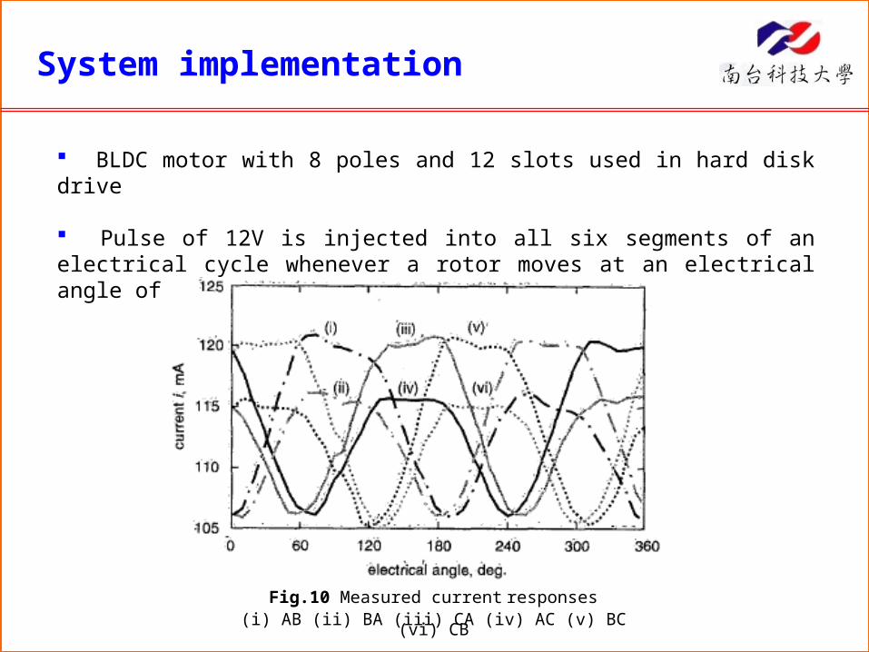
System implementation and experimental verification
Conclusions
Abstract
The paper proposes a method of identifying the rotor position of a brushless DC (BLDC) motor and driving a motor smoothly form standstill without position sensors.
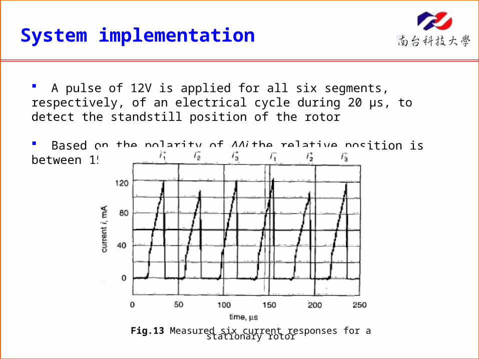
Six current pulses are injected into every two phases of the motor and their first and second differences are compared in order to obtain the standstill position of the rotor.
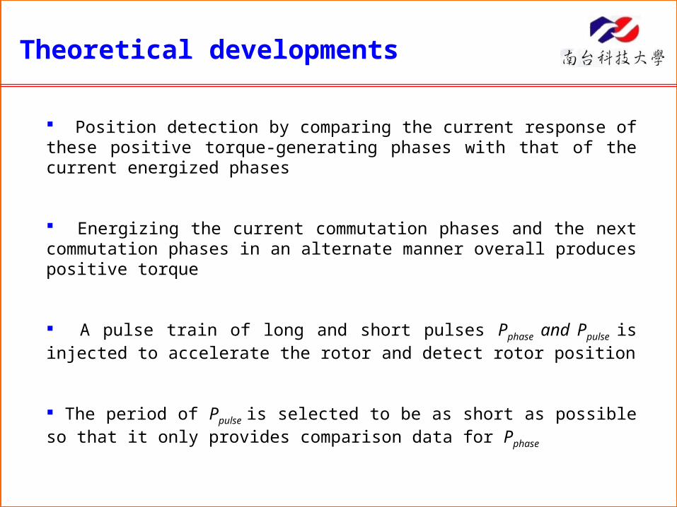
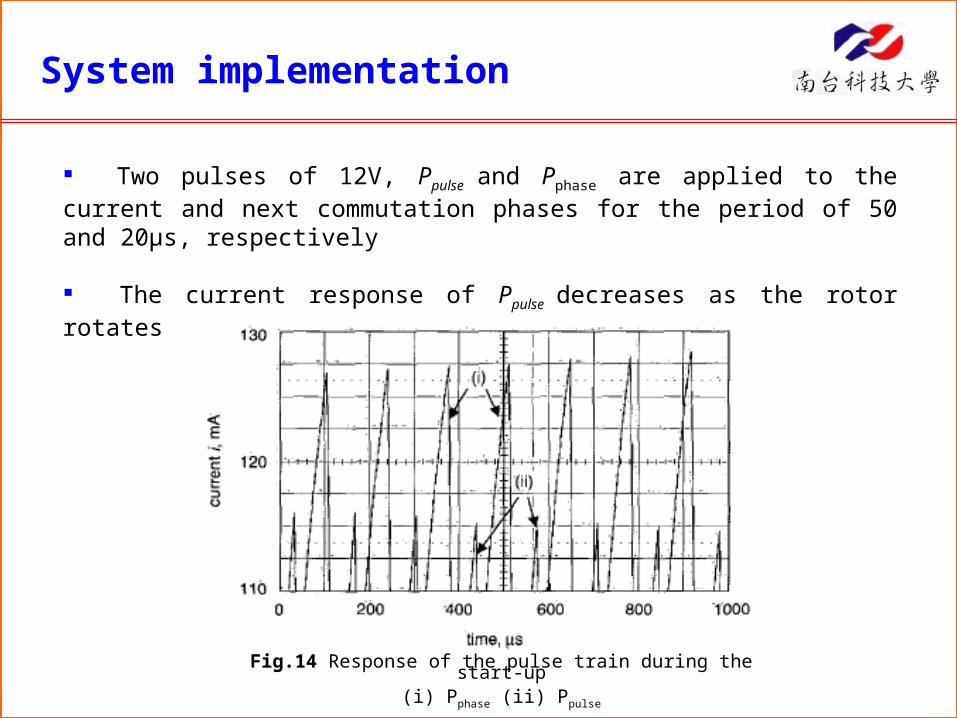
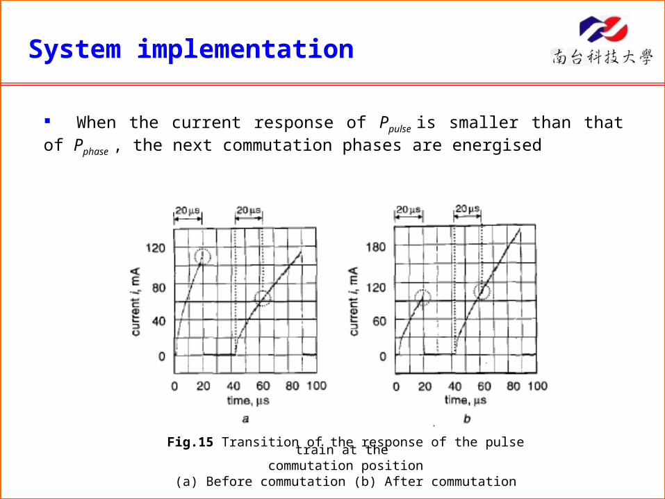
After start-up, a pulse train of alternating long and short pulses, is injected into the commutation phases and the current responses are monitored to get the next commutation timing. **** (poate modific)
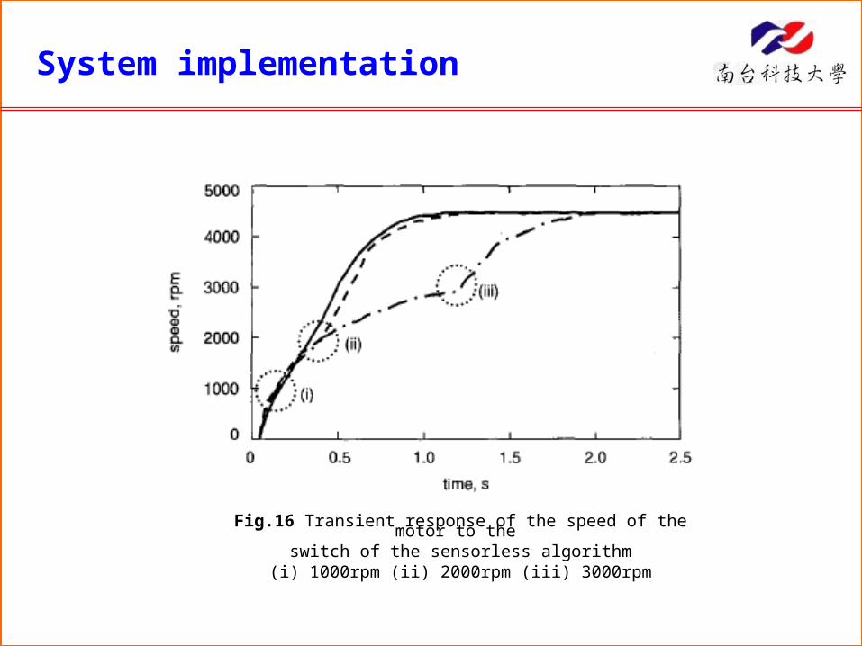
A DSP-based BLDC drive is developed in order to verify the algorithm experimentally. It shows the method can drive the motor smoothly up to medium speed without delay
Introduction
Brushless DC motors are widely used in various applications because of their high efficiency and good controllability over a wide speed range
Position information, required for energizing the correct armature windings, can be obtained by using hall sensors or encoders
Sensors can be affected by operating conditions and increase the size and cost of the motor
Sensorless methods have been developed for providing the position information without the above restrictions
Introduction
The popular back-emf (back electromotive force) method can only be used in high speeds and needs another initial rotor position detection method and a start-up algorithm
The ‘align and go’ start-up algorithm can be used, but it usually incurs a time delay due to aligning the rotor and reaching a sufficient speed for back-emf measuring
Other methods based on inductance variation have been researched, but they all present some drawbacks in actual implementation
This paper uses finite-element analysis to calculate the inductance of a BLDC motor and develops an initial rotor position detection and start-up algorithm, utilising the inductance variation without having the above drawbacks
Inductance variation
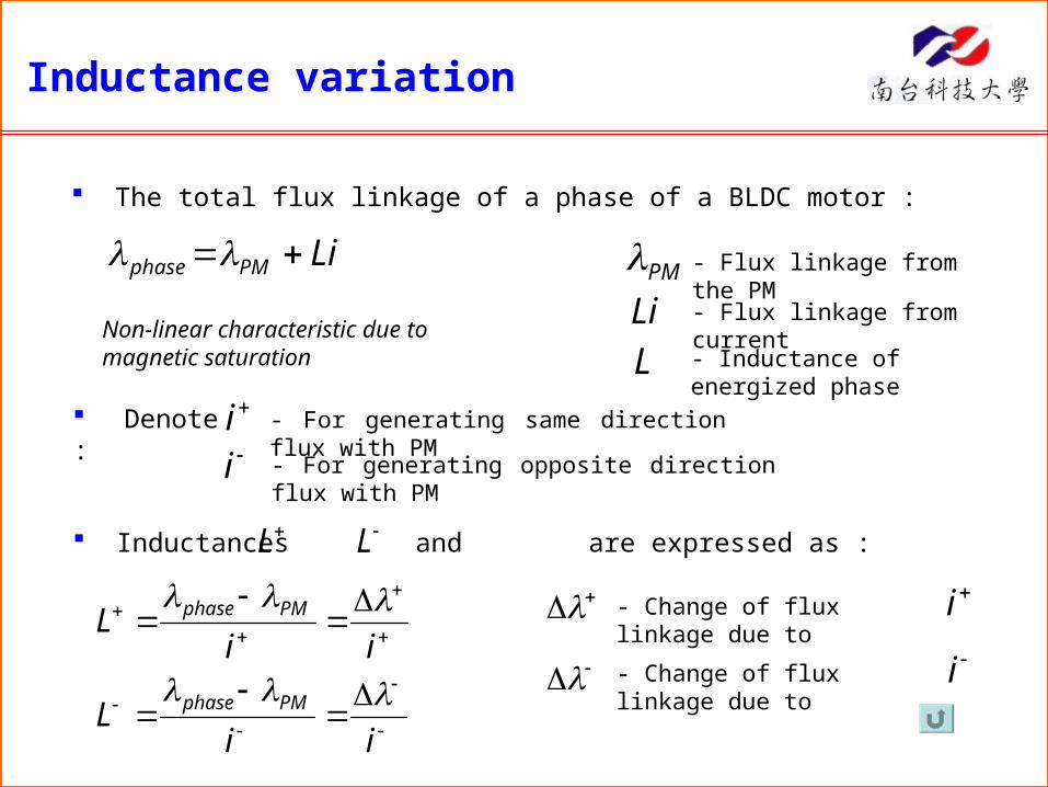
The total flux linkage of a phase of a BLDC motor :
LiPMphase PMLi
L
- Flux linkage from the PM
- Flux linkage from current
- Inductance of energized phaseNon-linear characteristic due to magnetic saturation
Denote : ii
- For generating same direction flux with PM
- For generating opposite direction flux with PM
Inductances and are expressed as :L L
iiL
iiL
PMphase
PMphase
- Change of flux linkage due to i
- Change of flux linkage due to i
Inductance variation
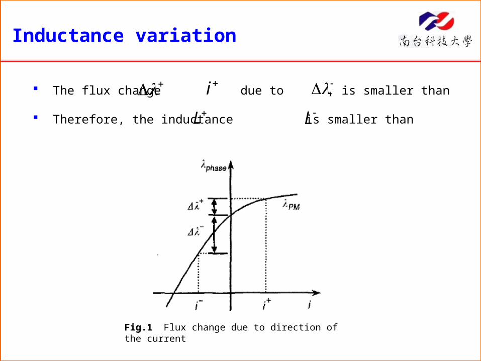
Fig.1 Flux change due to direction of the current
The flux change due to , is smaller than
Therefore, the inductance is smaller than
iL L
Inductance variation
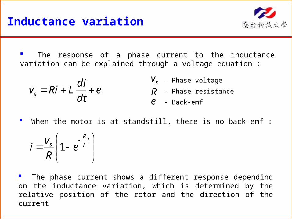
The response of a phase current to the inductance variation can be explained through a voltage equation :
sve
dt
diLRivs R
e
- Phase voltage
- Phase resistance
- Back-emf
When the motor is at standstill, there is no back-emf :
tL
Rs eR
vi 1
The phase current shows a different response depending on the inductance variation, which is determined by the relative position of the rotor and the direction of the current
Inductance variation
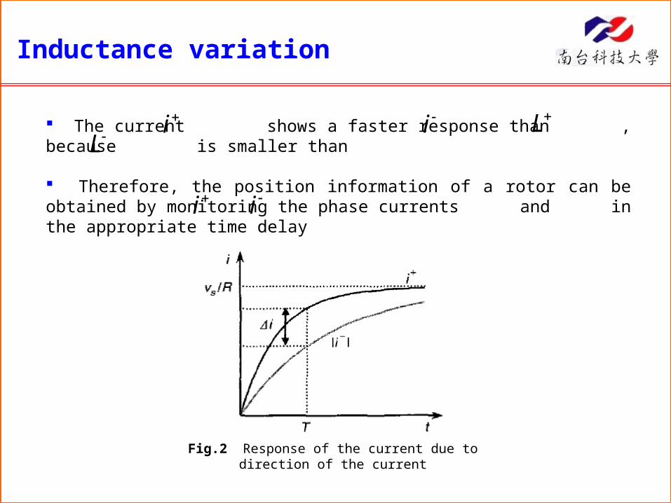
The current shows a faster response than , because is smaller than
Therefore, the position information of a rotor can be obtained by monitoring the phase currents and in the appropriate time delay
i i LL
Fig.2 Response of the current due to direction of the current
i i
Theoretical developments
CSdLAdSB
Finite-element analysis of a BLDC motor
The finite-element method (FEM) is used to calculate the magnetic vector potential of the BLDC motor
The total flux linkage of the phase can be expressed as :
BA
- Flux density
- Magnetic vector potential
The inductance is then determined by calculating the flux linkage from the energized phase and PM, and the flux linkage from the PM only
A 2D finite element program is developed to calculate the magnetic field of a motor with 8 poles and 12 slots
Theoretical developments
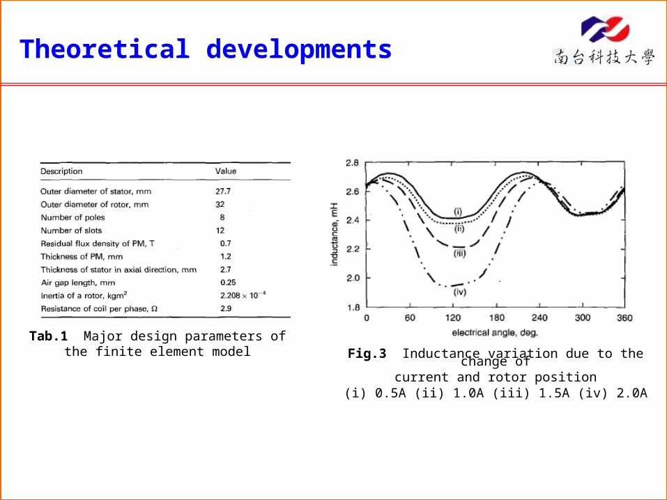
Tab.1 Major design parameters of the finite element model Fig.3 Inductance variation due to the change of
current and rotor position(i) 0.5A (ii) 1.0A (iii) 1.5A (iv) 2.0A
Theoretical developments
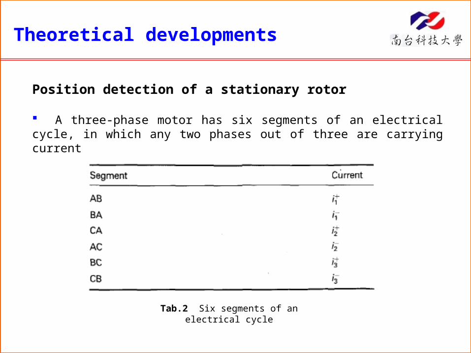
Position detection of a stationary rotor
A three-phase motor has six segments of an electrical cycle, in which any two phases out of three are carrying current
Tab.2 Six segments of an electrical cycle
Theoretical developments
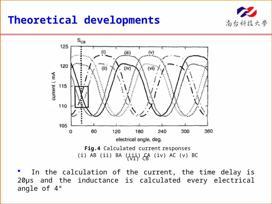
In the calculation of the current, the time delay is 20μs and the inductance is calculated every electrical angle of 4°
Fig.4 Calculated current responses(i) AB (ii) BA (iii) CA (iv) AC (v) BC (vi) CB
Theoretical developments
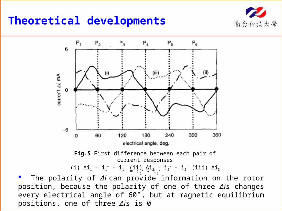
The polarity of Δi can provide information on the rotor position, because the polarity of one of three Δis changes every electrical angle of 60°, but at magnetic equilibrium positions, one of three Δis is 0
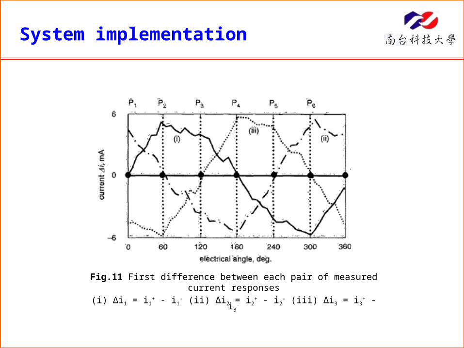
Fig.5 First difference between each pair of current responses(i) Δi1 = i1+ - i1- (ii) Δi2 = i2+ - i2- (iii) Δi3 = i3+ - i3-
Theoretical developments
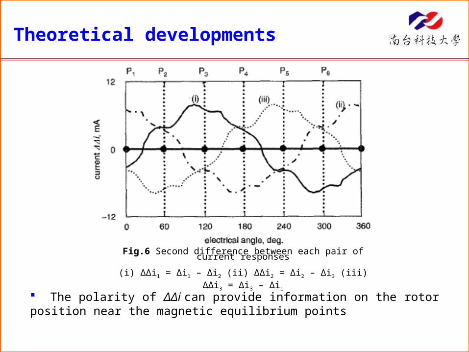
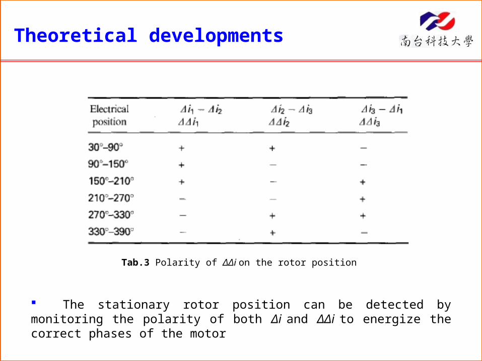
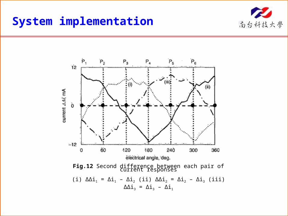
The polarity of ΔΔi can provide information on the rotor position near the magnetic equilibrium points
Fig.6 Second difference between each pair of current responses


![J : ; H Q : Y I J H = J : F F · Д-р психол. наук, профессор Стрелков В.И. J Z [ h q j h ] j f h l j _ g h [ j _ g _ ^ Z g b b Z n _ ^ j u: I j h l](https://static.documents.pub/doc/80x56/5f093b487e708231d425d956/j-h-q-y-i-j-h-j-f-f-f-.jpg)


![J Z [ h q j h ] j j ^ f l « l h j b h k k b b», « k h [ s ...ksosch.ucoz.ru/svedeniya-o-shk/OBRAZOVANIE/program... · J Z [ h q j h ] j j _ ^ f _ l « l h j b h k k b b», « k](https://static.documents.pub/doc/80x56/5f8607572f15b865c01d8a43/j-z-h-q-j-h-j-j-f-l-l-h-j-b-h-k-k-b-b-k-h-s-j-z-h-q-j-h-.jpg)