DEPARTMENT OF ELECTRICAL & ELECTRONICS AUTOCAD STARTING OF AUTOCAD:- To start AutoCAD, double click application icon on the windows desktop. If desktop icon is not created, pick Start → Programs AutoCAD. → Under standing Menu System:- When we start AutoCAD, We will see AutoCAD windows screen. The screen contain various components let us discuss these components & their significance. The main AutoCAD window screen can be tested as follows. 1. Pull Down Menu Bar. 2. Screen Menu. 3. Status line. 4. Drawing Area. 5. Curser. 6. Tool Bar. 7. Yes Icon. Menu Bar:- The Menu Bar appears on the top of the AutoCAD screen. It contains various commands in different categories &the pull down menu. Some of the pull down contains child menus represents sub commands. Screen Menu:- The Screen menu appears on the right side of the drawing window, which represents a set of commands. A command in this AutoCAD 2000 1
Transcript
DEPARTMENT OF ELECTRICAL & ELECTRONICS
AUTOCADSTARTING OF AUTOCAD:-
To start AutoCAD, double click application icon on the windows desktop. If desktop icon is not created, pick Start → Programs→AutoCAD.
Under standing Menu System:-When we start AutoCAD, We will see AutoCAD windows screen.
The screen contain various components let us discuss these components & their significance. The main AutoCAD window screen can be tested as follows.
1. Pull Down Menu Bar.
2. Screen Menu.
3. Status line.
4. Drawing Area.
5. Curser.
6. Tool Bar.
7. Yes Icon.
Menu Bar:-The Menu Bar appears on the top of the AutoCAD screen. It
contains various commands in different categories &the pull down menu. Some of the pull down contains child menus represents sub commands.
Screen Menu:-The Screen menu appears on the right side of the drawing window,
which represents a set of commands. A command in this menu may contain the set of sub commands. The command in this menu contains a set of sub commands, which appears on the sub menu. When that command is selected the screen contains full AutoCAD command set where as menu bar contains only that used commands when we select it in a screen menu another sub menu may appear which give sub commands. Click AutoCAD on the top of the screen menu to come to the
AutoCAD 2000 1
DEPARTMENT OF ELECTRICAL & ELECTRONICS
main menu of the screen menu. Click**** to get cursor menu [also called assist menu or tools menu].
The Status Line:-The status line displays the X&Y co-ordinates of the current cursor
position & also the button representing ON/OFF status of modes such as grid, ortho, these buttons out of toggle switches [we can double click on it to make its status ON/OFF]
Tool Bars:- It contains many icons of particular category to access a
command directly without using menu system. The toolbars consume a lot of space on the screen, which in turns limits drawing area. So they can be normally kept of f (use view→ toolbars).
Cursor Menu:-Curser menu appears on graphic window when mid button of
mouse (Or shift+ right mouse button) is pressed. The options under cursor menu are used to locate exact points like center, end point of objects. This helps to produce accurate drawings.
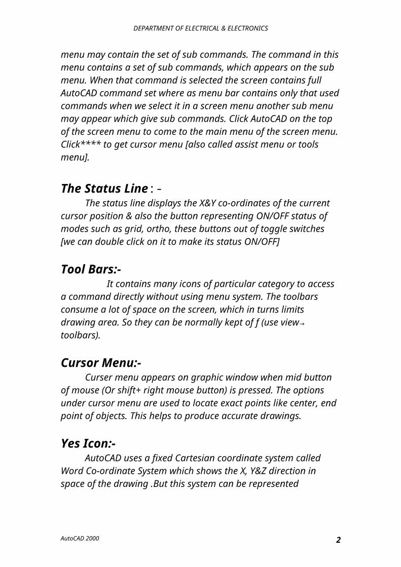
Yes Icon:-AutoCAD uses a fixed Cartesian coordinate system called Word
Co-ordinate System which shows the X, Y&Z direction in space of the drawing .But this system can be represented according user requirement. Then it is called as User Co-ordinate System (UCS).The UCS is represented by a UCS icon (Arrow in X And Y Direction) on the left corner of the screen. The letter W appearing in the UCS icon indicates the World Co-ordinate System(WCS).
WCS UCS
AutoCAD 2000 2
DEPARTMENT OF ELECTRICAL & ELECTRONICS
Dialog Box:-When some commands like point, style, insert, colour are selected
dialog box will appear. An image file displays a small representation of how a feature will appear in the drawing.
Command Prompt Area:-In this area commands can be entered using keyboard. Information
of sub commands & error messages are also displayed in this area.
Cursor (Cross Hair):-It is the thin cross line which moves respect to the movement of the
mouse. It locates the selection point.
Pick Box:-It is the small box of the center of the cursor or in some cases
without the cursor, which is used to select the object.
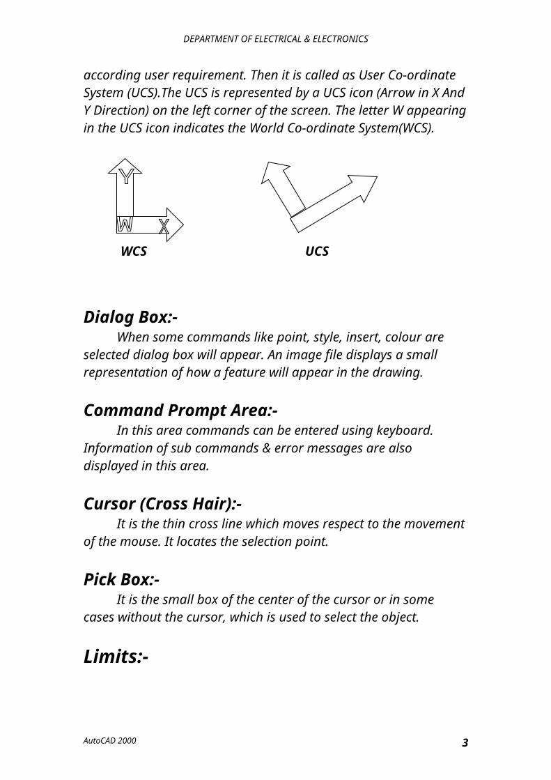
Limits:-Drawing limits is the invisible boundary to get the drawing. It
should be large enough to contain the drawing & other related parts of it.Commands: Limits press enter.Menu: FormatDrawing limits.ON/Off/<lower left corner><0, 0><: (0,) enter lower co-ordinate value & press enter.Upper right corner <12, 9> (30,200) enter the co-ordinate value enter.
Grid & Snap:-Grid:-
It is pattern of dots at a specified spacing that extends over the area specified by the limits. The grid gives a visual display on the screen of the distance between points. Using grid it is possible to directly pick
AutoCAD 2000 3
DEPARTMENT OF ELECTRICAL & ELECTRONICS
points on the screen at specific distance. These dots will not appear on print out of drawings.Command: GRID enter. Grid spacing (X) ON/OFF/SNAP/ASPECT<.5>: enter value (say 10) enter.
Snap:-The grid gives a visual display of positions on screen but is it is not
possible to pick exact position by eye judgment .So an option is given to set snap distance when snap is set , cursor movement is restricted. That is the cursor will move only in steps of snap distance. If snap is made off, the cursor movement will be smooth.Command: SNAP enter.ON/OFF/Aspect/rotate/style<0.5>: enter value (say B) enter.Grid, Snap, & other settings can be done by using the dialog box, which is occessed by menu.Menu: ToolsDrafting settings..Command: DORMODES enter.Enter X&Y spacing for grid & snap & click ok.
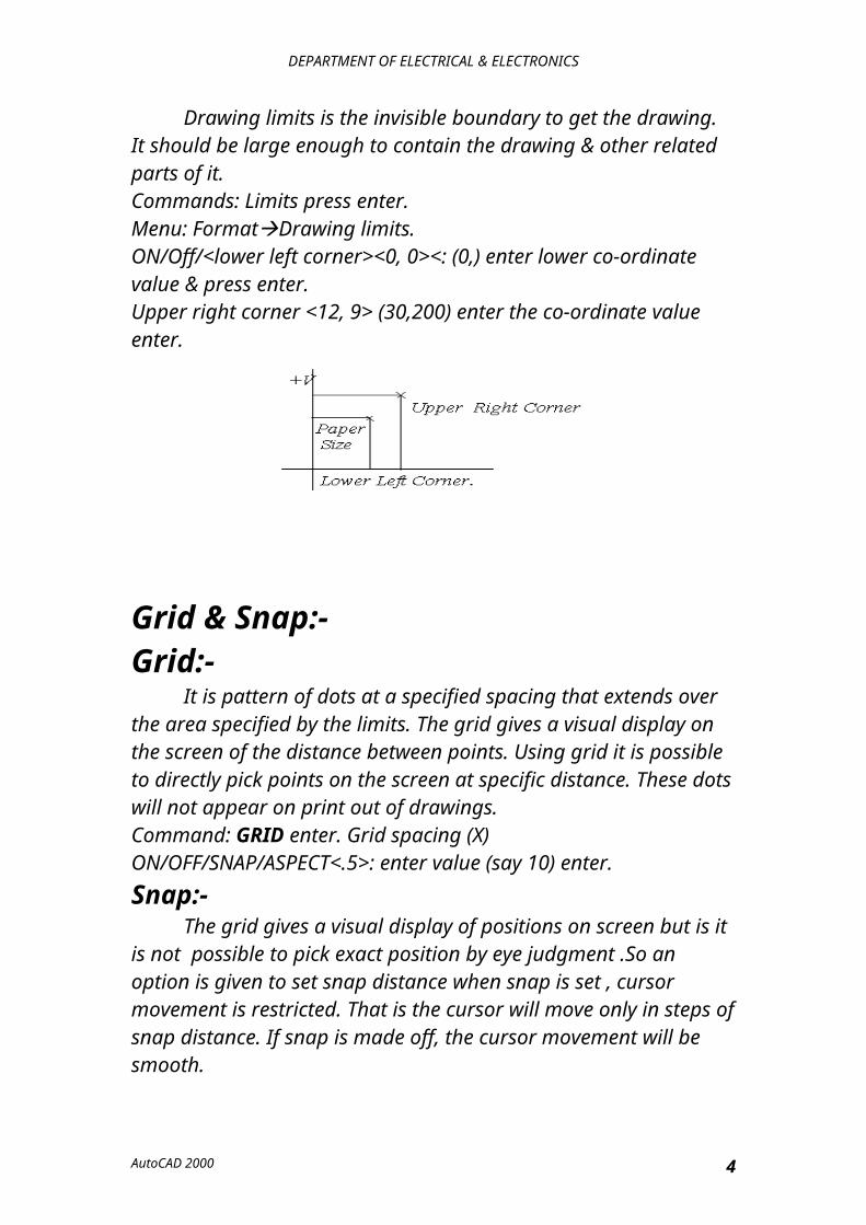
Basic Drawings:-Line: A line can be one segment of a series of connected segments.
Here such segments treated as a separate object.Command: LINE enter.Menu: Draw Line.
Method-1:From point: pick objects 1To point: pick 2To point: pick 3 & so onTo point: undo (u): to cancel previous segmentTo point: close (c): to join first & last pointTo point: press ENTER to stop the command
60
40
AutoCAD 2000 4
DEPARTMENT OF ELECTRICAL & ELECTRONICS
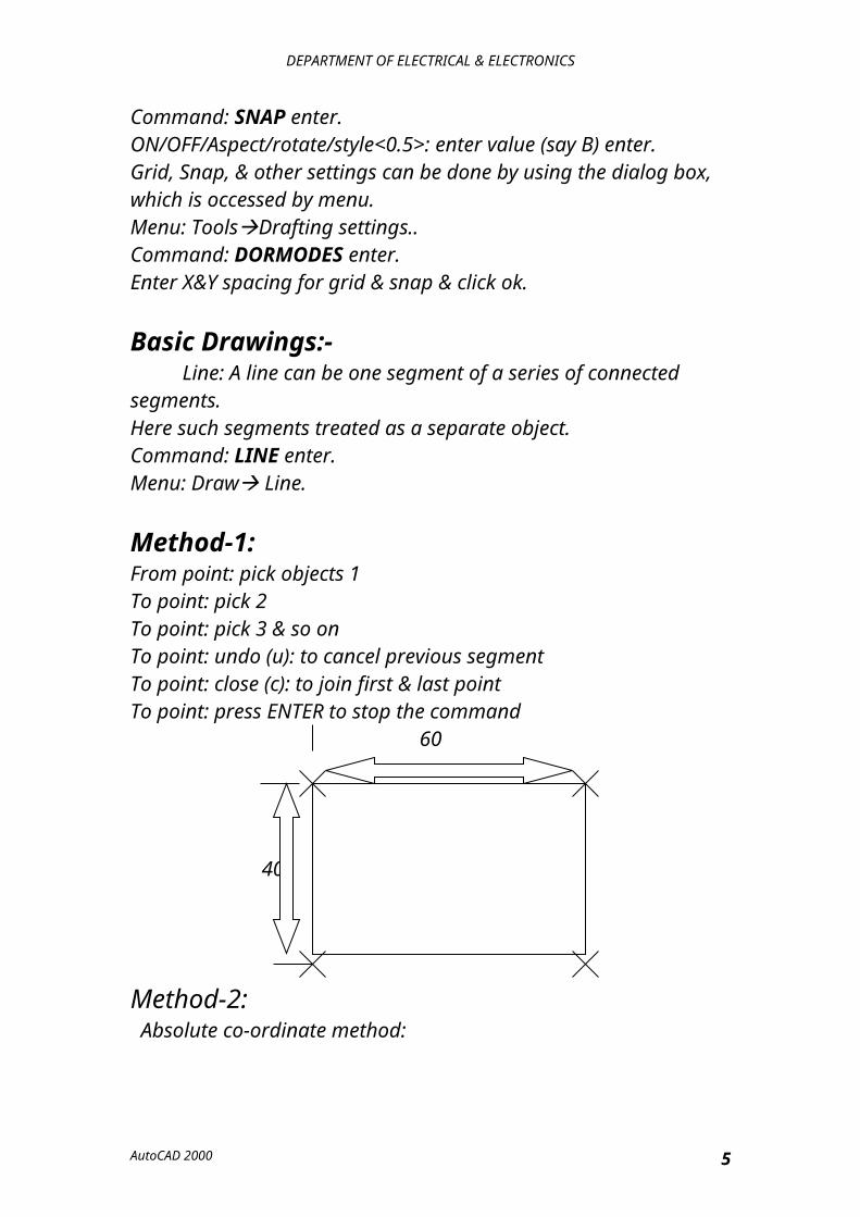
Method-2: Absolute co-ordinate method:Every point on the screen has X & Y co-ordinate (&Z co-ordinate in 3D drawings) so points can be selected by entering the co-ordinates of that point.From pint: type co-ordinate of starting points (that is 40, 30)To point:Type the coordinates of second point i.e.,100,30To point: 100, 70To point: 40, 70To point: c (for close)
(40,70) (100,70)
(40, 30) (100, 30)
Method-3:Relative co-ordinate methodIf the displacement of the current point is known with respect to the
previous point, the method can be used.From point: 120, 30(co-ordinate of starting point, absolute)To point: @60, 0 @-40,0 @0,40To point: @0, 40To point:@-60, 0To point:@-40 or c
@60,0
AutoCAD 2000 5
DEPARTMENT OF ELECTRICAL & ELECTRONICS
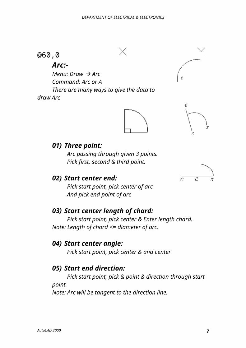
Arc:-Menu: Draw ArcCommand: Arc or A There are many ways to give the data to draw Arc
01) Three point:Arc passing through given 3 points.Pick first, second & third point.
02) Start center end:Pick start point, pick center of arcAnd pick end point of arc
03) Start center length of chard:Pick start point, pick center & Enter length chard.
Note: Length of chord <= diameter of arc.
04) Start center angle:Pick start point, pick center & and center
05) Start end direction:Pick start point, pick & point & direction through start
point.Note: Arc will be tangent to the direction line.
06) Start end Angle:Pick start point, pick, & point, type angle.
07) Start end radius:Pick start: pick end, type radius of arc or show radius by
mouse.08) Center start end:
Pick center, pick start point & end point.Center start AnglePick center point, pick start point end & enter angle(Counter clock wise from start point)
AutoCAD 2000 6
DEPARTMENT OF ELECTRICAL & ELECTRONICS
09) Center starts length of chard:Pick center point, pick start point, & enter length of chard.
10) Continue:Arc will continue from the previous arc end point in the
same direction. Then pick the second point of the arc.
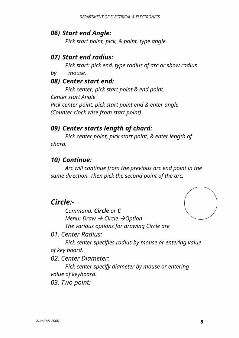
Circle:-Command: Circle or CMenu: Draw Circle OptionThe various options for drawing Circle are
01. Center Radius: Pick center specifies radius by mouse or entering value of key board.02. Center Diameter: Pick center specify diameter by mouse or entering value of keyboard.03. Two point:
Circle passes through specified two points or diameter points. Pick first point, pick second point.04. Tan-Tan-Rad:
Draw a circle tangential to any 2-selected object. Pick first tangential object. Pick second tangential object. Enter radius for circle.05. Tan-Tan-Tan:
Draw circle tangential to three –selected object: pick first, second, third object.06. Three Point:
Circle passes through specified three points pick first, second, third point.
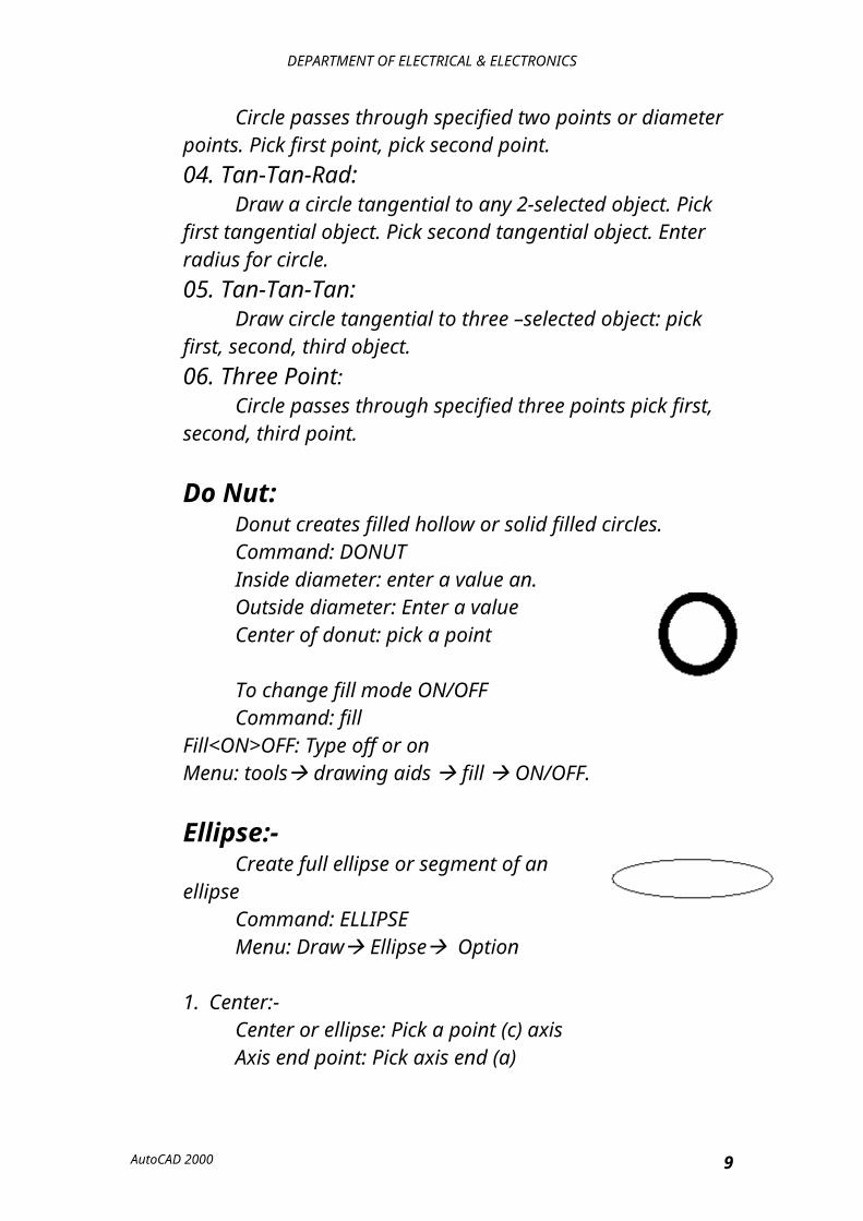
Do Nut:Donut creates filled hollow or solid filled circles.Command: DONUTInside diameter: enter a value an.Outside diameter: Enter a valueCenter of donut: pick a point
AutoCAD 2000 7
DEPARTMENT OF ELECTRICAL & ELECTRONICS
To change fill mode ON/OFFCommand: fill
Fill<ON>OFF: Type off or onMenu: tools drawing aids fill ON/OFF.
Ellipse:-Create full ellipse or segment of an ellipseCommand: ELLIPSEMenu: Draw Ellipse Option
1. Center:-Center or ellipse: Pick a point (c) axisAxis end point: Pick axis end (a)<Other axis distance>/rotation: pick a point (D) or specify a distance using key board (2D)
2. Axis End:-Arc/Center/<Axis end point 1>; pick a point (A)Axis end point 2; pick point (B)<Other axis distance>/ rotation: pick a distance from the center or specify a value or pick rotation from screen menu & specify an angle of rotation.
3. Arc:-Creates a segments of ellipse<Axis End Point>/ center: pick a point (A)Axis & End point: pick second point of the axis (B)<Other axis distance>/rotation: specify a distance or rotation or previous parameter/ <start angle>: pick a start position of arc(S)Parameter /Include /<end point>: point end of arc (E)
Polygons:-Creates a regular polygon of given number of sides (3-1024)Command: polygon prices Command: Draw polygonPolygon number of sides<4>: Specify the number of radius for polygon (6)Edge/Center<Center of polygon>: pick center point (c)
AutoCAD 2000 8
DEPARTMENT OF ELECTRICAL & ELECTRONICS
Inscribed in circle / circumscribed about circle.(I/C) <1>: pick 1 or C from screen menu.Radius of circle: pick radius from center or type a value by key board.
Edge Method:-Defines a polygon y specifying the end point of the first edgeEdge/<center of polygon>: pick edge from screen menuFirst end point of edge: pick a point (A)Second point of edge: pick a second point (B)
Rectangle:-Creates a rectangle by using 2 specified corners .The rectangle acts 1 object instead 4 individual lines.Command: Rectangle.Menu: Draw Rectangle Chamfer/ elevation / fillet /thickness / width /<first corner>: pick 1 corner rectangle 1 or required option for the screen menu .Other corner: pick opposite corner of rectangle (2)
Fillet:-Creates a rectangle with corner rounded off fillet radius for
rectangle specify radius of filtering are (S)
Thickness:-Creates extended rectangle Thickness for rectangle: Specify the height of box.
Width:-Draw a wide rectangleWidth for rectangle: Specify the line width (B)
Points:-Creates a point object.
Step1:- Setting of point styleCommand: DDPTYPEMenu: Format point style.
A point Style dialog box will appear choose a point style- using mouse, specify a size, & click on ok.
AutoCAD 2000 9
DEPARTMENT OF ELECTRICAL & ELECTRONICS
Step2:- To draw point objectCommand: point
Menu: Draw Point Option.(a) Single Point;- Creates only one point at selected location
Point: Pick a place(b) Multiple Point; - Creates a series of points at selected locations
Point: pick places, press enter to stop command.
Modify Tools:-Drawing its basic object & then modifying it to get the
desired object can create any complex object. In this chapter let us discuss the various commands used to modifying the object.
Erase:-Deletes selected objectsCommand: E or EraseMenu: modify Erase
Select Objects: Select object by pick pox or by selection window
Move:-Objects can be classified from a place with in the following
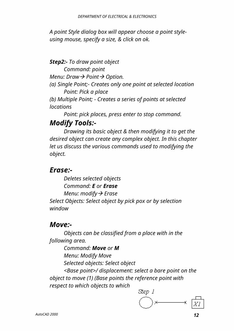
area.Command: Move or MMenu: Modify MoveSelected objects: Select object<Base point>/ displacement: select a bare point on the
object to move (1) (Base points the reference point with respect to which objects to which move) second point of displacement: pick second point to place the object s.Step 1: Draw Object.Step 2: Move rectangle Step 3: Move Circle
AutoCAD 2000 10
DEPARTMENT OF ELECTRICAL & ELECTRONICS
Copy:-To create one or number of copies, selected objects with in
drawingCommand: Copy or CPMenu: Modify CopySelect Object: Select object to copy <Base point or displacement>/ multiple: pick a base point
(for single copy) or pick multi line from screen menu & pick base point (for multiple copies) second point of displacement: pick second point(S) to place to object.
Rotate:-Rotate selected objects around given axis to the given angleCommand: RotateMenu: Modify RotateBase Point: pick a base point (point above which object rotate) <Rotation angle> / reference: specify on angleReference: This option is used to align one object to another by specifying points. (Rotational angle) / reference: type R or pick reference from
the screen menu. Reference angle<0>: pick a point (1) on reference line (refer figure b)
Second point: point (2) on reference lineNew line: pick point (3) on new angleStep: 1 Draw objectsStep: 2 rotate 90 degreeFig (a) rotate command Fig (b) rotate command reference option 1x B
AutoCAD 2000 11
DEPARTMENT OF ELECTRICAL & ELECTRONICS
Step 1
Step 2
Break:-To cut off an object in 2 parts at selected point or to remove
part of the object in between 2 selected pointCommand: BreakMenu: Modify Break Select option from screen menu
1. Select Second:Select object: select object to breakEnter second point or (F or First point): pick second point
on the object.2. Select Point:
Select point: pick a point of object where it is to break3. Select Two Points:
Select object: Select object to break.Enter first point: pick point in the object.Enter second point: pick another point on the object.
Trim:-To cut off or erase on object precisely at an edge defined by
one or more objects. Can also be used to cut off that object in between two defined edges.
Command: Trim or TRMenu: Modify TrimSelect coating edges: select the boundary edges for trim
edge (1) fig. (A). < Select object to trim>/project/edge/undo: pick edges of the objects to form (3) or pick required option front screen menu.
Options:
AutoCAD 2000 12
DEPARTMENT OF ELECTRICAL & ELECTRONICS
Project is used in 3D space.Edge: Determined whether objects are trimmed when the
cutting edge physically intersected with the objects to be trimmed or even when they inserted at an imaginary point after extending the cutting edge.
Extend/next<correct>: Enter option extend or no extend & then picked.Fig (a) Trim Command Fig (b) Option for trim
Edge to trim
Scale:-Enlarges or reduces size equally in X, Y&Z according to the
scale factor given. If scale factor is greater than 1, object is large & if it is less than 1, object is reduced.
Command: ScaleMenu: Modify Scale.Select objects: select all objects, which are to be selectedBase point: specify a point on the object<Scale factor >/reference: specify a scale factor (2) or type
R for reference.
For Reference:Reference length<1>: specify a distance (1&2)New length: specify a distance or pick
OriginalScale
0.5
Extend:-
AutoCAD 2000 13
DEPARTMENT OF ELECTRICAL & ELECTRONICS
Extend the ends of selected object of precisely nut at a boundary defined by another object.
Command: ExtendMenu: Modify ExtendSelect object: Select the object (1) to make boundary for an
extension press <select object to extend>/project/edge/undo: select object (2) to be extended or enter option.
Options:Project; Used in 3D spaceEdge: Determined weather object is extending to another
object imaginary object projected & or only to as object that actually intersects with it
Extend/no extend<correct>: Enter Option.
Extend:Extend the ends even through the boundary is not actually
intersecting with it after extending. No Extend:
Object will not extend it the boundary object does not interact with it after extending.
Offset:-Off setting creates a new object that is similar to a selected
object at specified distance. It may be used to create concenter circles, shapes, parallel lines etc.
Command: OffsetMenu: Modify Offset.Offset distance or through: specify a distance or for trough
point. If distance is specified copies object at given distance from selected object
Select object to offset: Select one object.Side of offset: Specify a side (1) with reference selected
object. If the inertia: Offsets object at a selected pointSelect object to offset: pick the object.
AutoCAD 2000 14
DEPARTMENT OF ELECTRICAL & ELECTRONICS
Through point: pick a point (1) where offset object is required.
Fillet:-Filleting connects the two objects with a smoothly are of a
specified radius.Command: FilletMenu: Modify Fillet.(Time mode). Curent filet radius 0.5.Poly line/Radius/Trim/<select first object>: click on radius
on screen menu or any other option.Enter fillet radius (0.5): Specify a radius.
Command: A gain selects the commands fillet from screen menuPoly line/radius trim<select first object>: pick one object.Select second object: pick second point.
Options:Poly line: If poly line is selected, fillets every corner of it
extra length at the end of the object beyond the arc is cut off. If no trim is taken, object retains its length while fillet arc is created.
Chamfer: Connects two parallel lines by extending them to insert or the join with a leveled line at specified distance from intersection.
Command: Modify Chamfer(No trim mode) Current chamfer distance 1:05, distance 2:05Poly line/distance/angle/trim / method/< first line>: check on distance or enter first chamfer distance<.5>: specify the valueEnter second chamfer distanced<6>: specify the valuePoly line/distance/Angle/Trim/method/< first line>: Select first lineSelect second line: pick second lineOptions:
Poly line, trim. (Same as fillet)Angle: Chamfering will be taken at given of distance from first selected line.Enter chamfer angle from first line: specify (60)Poly line/ distance/angle/trim/method< first line> pick first line
AutoCAD 2000 15
DEPARTMENT OF ELECTRICAL & ELECTRONICS
Select second line pick second lineMethod: Restricts the AutoCAD to perform trimming in distance method on angle method. 152 Dist1-15 1 Dist 2-25 No Trim Dist-25 Trim1 Angle -15
CHAMFER COMMAND
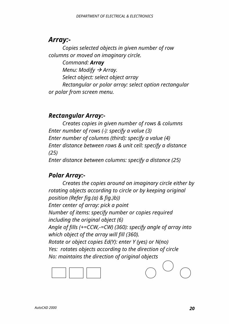
Array:-Copies selected objects in given number of row columns or
moved on imaginary circle.Command: ArrayMenu: Modify Array.Select object: select object arrayRectangular or polar array: select option rectangular or
polar from screen menu.
Rectangular Array:-Creates copies in given number of rows & columns
Enter number of rows (-): specify a value (3)Enter number of columns (third): specify a value (4)Enter distance between rows & unit cell: specify a distance (25)Enter distance between columns: specify a distance (25)
Polar Array:-Creates the copies around on imaginary circle either by
rotating objects according to circle or by keeping original position (Refer fig.(a) & fig.)b))Enter center of array: pick a pointNumber of items: specify number or copies required including the original object (6)Angle of fills (+=CCW,-=CW) (360): specify angle of array into which object of the array will fill (360).Rotate or object copies Ed(Y): enter Y (yes) or N(no)Yes: rotates objects according to the direction of circle
AutoCAD 2000 16
DEPARTMENT OF ELECTRICAL & ELECTRONICS
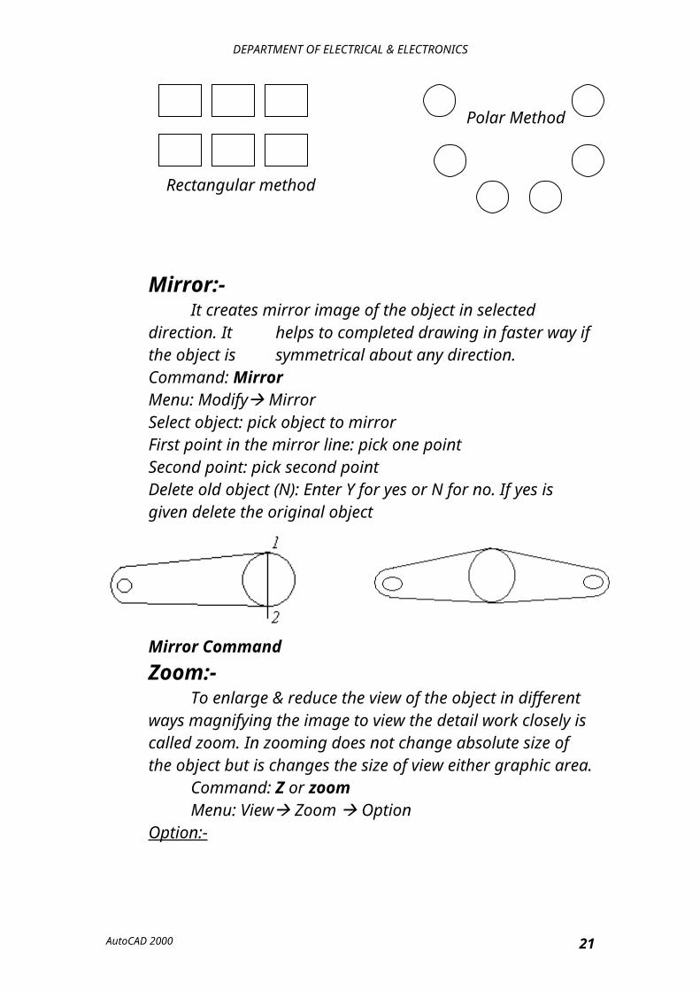
No: maintains the direction of original objects
Polar Method
Rectangular method
Mirror:-It creates mirror image of the object in selected direction. It helps to completed drawing in faster way if the object is symmetrical about any direction.
Command: MirrorMenu: Modify MirrorSelect object: pick object to mirrorFirst point in the mirror line: pick one pointSecond point: pick second pointDelete old object (N): Enter Y for yes or N for no. If yes is given delete the original object
Mirror Command
Zoom:-To enlarge & reduce the view of the object in different ways
magnifying the image to view the detail work closely is called zoom. In zooming does not change absolute size of the object but is changes the size of view either graphic area.
Command: Z or zoomMenu: View Zoom Option
Option:-1. Windows: - Enlarges the view of objects selected within the
window to the full screen.2. Previous: - The previous view will be back (we can revert up to
10 steps) that is returns quickly to the prior view.
AutoCAD 2000 17
DEPARTMENT OF ELECTRICAL & ELECTRONICS
3. All:- Zoom all displays the enter drawing even if they are out side the graphic area with the full view of paper limits, while displaying zoomed view drawing is regarded.
4. Extents: - Zoom extent displays largest possible view of all objects in the drawing.
5. Center: - To resize the view of the object by moving specified center point to center of graphic area & given magnification to height of graphical area.
Center point: Pick to center at area to be zoomed.Magnification of height:Pick two points to specify the distance or enter the value.6. Dynamic:-
The area of zooming can be selected dynamically by zoom box. The aspect ratio of zoom will be same as graphical area. To change the size of zoom box press first button of move position of the zoom box to select the correct location & press enter key or right button of mouse.7. IN &Out: - Reducing the images at see a larger position of the
drawing is called zooming out & magnifying the image to see the point closely is called zooming in. The changes the display is predefined increments (Double or ½).
8. Scale: - Increases or decreases size of the image by the scaling can be given with reference to the drawing limits or to the correct view. To scale a view relative to limits enter a simple scale factor end enter.
(1= full size< 1 enlarges view>1 reduces the view)The original size will be referred while zooming the view not
the percent view size.The scale view relative to present view on graphic area.
Enter a scale factor followed by X EX: 2X.9. V Max: - Zooms out of per as possible on the graphic axis vertical screen without having a complete regeneration of the drawing.
The vertical screen is defined as the area on which the screen is re-down with zoom command rather the regeneration of the drawing. If fast zoom it off: display changes with always with regeneration of the drawing. If zoom is on, regeneration takes place with the given specified resolution. Decreasing the resolution affects the view after zooming that is areas & circle look like made up of line.
AutoCAD 2000 18
DEPARTMENT OF ELECTRICAL & ELECTRONICS
10.Real Time: - Dynamically increase or decrease every image on the screen: press pick button down & move mouse to up of down to get required zoom. To stop press last button of mouse & pick exit.
OPTIONS OF ZOOM COMMAND
Object Snap:-Using object snap is a quick way to locate exact position on an
object with out having to know co-ordinate of drawing.
Options:- 1. End Point: picks insert end point of selected object from the pick
point.2. Mid Point: pick middle point to selected object3. Intersection:
Select nearest intersection of the objects from the cursor point.4. Apparent intersection: If the intersection is not physically visible but by extending them if they intersect at any one point, selects that invisible intersection. Pick one object, pick second object.5. Center: Selects center point of one arc, circle, or ellipse.6. Quadrant: Selects nearest quadrant point of selected circle or ellipse.
AutoCAD 2000 19
DEPARTMENT OF ELECTRICAL & ELECTRONICS
7. Tangent: Creates a tangential objected to selected arc circle or ellipse.8. Node: This is used locate center of point objects.9. Insertion: Select insertion point of block test etc. which is already assigned which exacting them.10. Perpendicular: Select a point on the object that forms a normal or perpendicular alignment with another object or with & imaginary extension of the object.11. Nearest: Select a nearest point on the nearest object from the cursor point.12. Quick: This is used in conjunction with other snap modes it selects a point which is the first eligible point it finds. It reduces the time taken to process in finding the correct point by analyzing which point is closer to the curser (not valid for intersection mode).13. None: Causes or disables both single & running object snap modes.14. Tracking: used to locate a point by tracking any other object same point. For example to select an intersection of mid points of two 90 angled lines tracking mid point of line, mid point of second line, press enter the stop tracking.15. Forms: to select a point at a distance from selected base point. Pick base point, Keep cursor in correct direction, enter distance will be located on the imaginary line joining base point & cursor.
AutoCAD 2000 20
DEPARTMENT OF ELECTRICAL & ELECTRONICS
Poly Line:-It is a series of connected line to arc segments
created on one object width for the objects also can be controlled.Command: PL or PLine.Menu: Draw Poly LineFrom Point: pick a pointArc/close/half width/length/undo/width/<end point of line>P pick end point of line 1 or enter required options
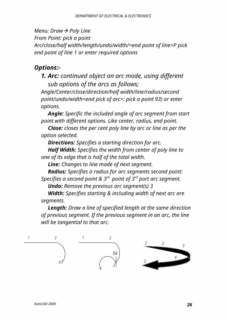
Options:-1. Arc: continued object on arc mode, using different sub
options of the arcs as follows;Angle/Center/close/direction/half width/line/radius/second point/undo/width<end pick of arc>: pick a point 93) or enter options.
Angle: Specific the included angle of arc segment from start point with different options. Like center, radius, end point.
Close: closes the per cent poly line by arc or line as per the option selected.
Directions: Specifies a starting direction for arc.Half Width: Specifies the width from center of poly line to one of
its edge that is half of the total width.Line: Changes to line made of next segment.Radius: Specifies a radius for arc segments second point: Specifies
a second point & 3rd point of 3rd port arc segment.Undo: Remove the previous arc segment(s) 3Width: Specifies starting & including width of next arc are
segments.Length: Draw a line of specified length at the same direction of
previous segment. If the previous segment in an arc, the line will be tangential to that arc.
AutoCAD 2000 21
DEPARTMENT OF ELECTRICAL & ELECTRONICS
Poly Edit: To make changes in selected poly lineCommand: PeditMenu: Screen menu P editsSelect poly lint: pick a ply line objectClose/join/width/edit/fit/split/de curve/<type gen./undo/exit: Enter option required.Options:Close: Close the open point of poly line using line segmentOpen: Opens the closed point of poly line segmentWidth: Specify a constant width for all segments. Enter new width for allSegments: Specify a width
The above 3 options are illustrated in the following figure.
Original Close Width=5
The other options are as follows: Fit: Creates a smooth curve passing through vertex points of
selected poly line. SP line: Creates a smooth curve passing through the mid
points of the segments of poly line. De Curve: Converts all curved in to selected poly line in to
lines. Join: Joins only arc, lines, or poly line to the nearest poly
line.
Fit curve
AutoCAD 2000 22
DEPARTMENT OF ELECTRICAL & ELECTRONICS
L Type Generator: - Generates the L type in continuous pattern through the vertical of the poly line. If off generates the line type starting & ending with a dash at each vertex line type generator does not affect the poly line with tapped segment.
L-type Gen On. L-Type Gen Off.
Undo: - Cancels the changes made in poly edit option.Edit: - Exit poly edit command.Edit Vertex: - This is used to make changes in the vertex of a selected poly line. Across(X mark) will appear on vertex, which shows the vertex to edit.Next: Moves X mark to the next vertex.Previous: Moves X marks to the previous vertex.Insert: Inserts one new vertex at selected point in between precut vertex & next vertex.Enter location of new vertex: pick a point (1) Move: Moves selected vertex from one place to another place.Enter new location: pick a point (2)
2 Original insert Move
1 1 s Figs (a) Edit vertex inserts Fig (b) Edit vertex move fig(c)width.Width: - Change starting & ending width of next segment.Enter starting width: Specify a value (refer fig c))Enter ending width: Specify a valueStraighten: - Any segments & vertices between selected two verticals will be deleted making a straight line.Next/previous/go/exit: goGo: Activates the straightening process
AutoCAD 2000 23
DEPARTMENT OF ELECTRICAL & ELECTRONICS
Break: - Removes the segments & vertical between selected row vertices, by making scanning segments or separate objects.Next/previous/go/exit: pick the next vertexNext/previous/go/exit: goRegion: regenerates the drawing Exit: exit the edit vertex sub menus.Tangent: attracts a tangent direction to the current vertex for use like in curve filling.Direction of tangent: specify a using move or specify an angle
S c s c1
Straighten Break
Hatch:-Hatching takes a specified area in the drawing, with a pre-defined
pattern.Command: BHATCHMenu: Draw HatchA hatch dialog box will appearClick on the pattern boxSelect suitable pattern (click for star mark)Click on okEnter suitable scale
Other options:-Select object: Select objects by pick box. This method is required
for open object as pick point is valid for only closed objects.Associated: If ON, then hatching is associated with the boundary i.e., if the boundary is modified after hatching, hatching will also change according to the changed boundary.
AutoCAD 2000 24
DEPARTMENT OF ELECTRICAL & ELECTRONICS
If OFF hatching will be an independent cutting which does not change according to the change of boundary.
Explode:-On: Each line in hatching will act as independent object.Off: Full hatching will acts as one object.
Boundary Set: Analysis of all objects in a complex section of a hatching boundary is time consuming for the complex, If a small area of a complex draw hatched define a boundary set which make it complete to analysis only objects inside the specified boundary set.Boundary Advance New boundary set.Specify corner points of a boundary set.[Crossing or window selection are enters]Click on OKThen using pick point option pick a point inside that boundary to hatch.
Hatch Style:-Normal: If a group of objects are taken as boundary hatched alternate boundaries.Outer: Only outer most boundaries will be hatched ignoring all inner boundaries.Ignore: Completely hatches the object by ignoring inner objects.
Blocks:-A block is a group of objects associated together to form is single
object. If any component is used frequently in the existing drawing or any other drawing, create one object & save it as a block. This block can insert & rotated whenever required.Command: Bmake or B press enterMenu: Draw Block Make
AutoCAD 2000 25
DEPARTMENT OF ELECTRICAL & ELECTRONICS
A dialog box will appearsType the name for this block.Click on select point & pick points on the object of reference in certain (this point will be used as a reference point while inserting the block)Click on select object & select object which are to be included in the blockRetain object: ON/OFF If O original objects will remain in same locationIf OFF original objects will be deleted. Click on OK.
Insert:-This command is used to insert a block in any other drawing file or
it was in any other format into the current file.Command: InsertMenu: Insert Block.A dialog box will appearSelect required block more or drawing file name by clicking all them.Click on OKInsertion Point: pick a point.
Insertion Point: - Scale factor<1>/corner/XYZ: enter a scale factor Y scale factor (Default=X): Enter scale factorRotation angle<0>: Enter an angle
Explode: - On-each object in the block will be individual object as an original drawing.OFF-all objects in block acts as one object.
W-Block: - Converts a selected block as a drawing file which can be inserted in any drawing or open respectively.Command: W blockCreate file: Dialog box will appears. Type name of the file to save press enterBlock name: Specify a block name to make a drawing file.