Auto-Continuum ™ Systems Automated MIG Welding Systems Issued Oct. 2016 • Index No. AU/10.0 Processes Advanced MIG processes: Versa-Pulse ™ Accu-Pulse ® MIG (GMAW-P) RMD ® MIG (GMAW) High-deposition MIG (GMAW) Flux-cored (FCAW) Input Power Auto-Line ™ 230 – 575 V 3-phase, 50/60 Hz Rated Output at 104°F (40°C) 350: 350 A at 31.5 V, 100% duty cycle 500: 500 A at 39 V, 100% duty cycle Output Range 350: 20 – 400 A, 10 – 44 V 500: 20 – 600 A, 10 – 44 V Industrial Automation Construction equipment Automotive components Recreational vehicles Farm machinery Office furniture Mining machinery Power source is warranted for three years, parts and labor. Original main power rectifier parts are warranted for five years. Easy to add capabilities FLEXIBLE More power, better reliability MORE WELD POWER 26% Better weld quality ADAPTIVE ARC FOR A CONSISTENT WELD Easy to set up and install for EtherNet/IP ™ , DeviceNet or Analog protocols SIMPLE INTEGRATION Quick Specs The Auto-Continuum system features an adaptive arc with less spatter and improved gap handling, providing increased travel speeds and high-quality welds on a variety of base materials. Simple integration with fixed and flexible robotic systems. Integrated Welding Intelligence ™ solutions. Delivers information to measure and improve your welding operation. See page 4 for more information. Take your welding to the next level. Next generation automation welding solution delivers advanced arc performance to improve throughput and weld quality. Auto-Continuum 350 and Auto-Continuum wire drive motor assembly shown. Miller Electric Mfg. Co. An ITW Welding Company 1635 West Spencer Street P.O. Box 1079 Appleton, WI 54912-1079 USA MillerWelds.com Equipment Sales US and Canada Phone: 866-931-9730 FAX: 800-637-2315 International Phone: 920-735-4554 International FAX: 920-735-4125
Transcript
Auto-Continuum™Systems Automated MIGWelding Systems
Power source is warranted for three years, parts and labor.Original main power rectifier parts are warranted for five years.
Easy to add capabilities
FLEXIBLE
More power, better reliability
MORE WELDPOWER26%
Better weld quality
ADAPTIVE ARC
FOR A CONSISTENT WELD
Easy to set up and installfor EtherNet/IP™, DeviceNet
or Analog protocols
SIMPLEINTEGRATION
QuickSpecs
The Auto-Continuum systemfeatures an adaptive arc with less spatter and improved gaphandling, providing increasedtravel speeds and high-qualitywelds on a variety of basematerials. Simple integrationwith fixed and flexible roboticsystems.
Integrated Welding Intelligence™
solutions. Delivers information to measure and improve yourwelding operation. See page 4 for more information.
Take your welding to the next level.Next generation automation welding solutiondelivers advanced arc performance toimprove throughput and weld quality.
Miller Electric Mfg. Co.An ITW Welding Company1635 West Spencer StreetP.O. Box 1079Appleton, WI 54912-1079 USA
MillerWelds.comEquipment Sales US and CanadaPhone: 866-931-9730FAX: 800-637-2315International Phone: 920-735-4554International FAX: 920-735-4125
2
Auto-Continuum™ System
All-new wire drive motor assembly
New low-inertia motor provides faster response for the best arc starts with the leastamount of spatter.
Reduced-weight design allows for quicker point-to-point arm movement and providesimproved servo motor life.
• Easy communication from robot and power source
• New wire drive motor assembly design utilizes common Miller mounting configurations
• Designed for easy integrationwith fixed and flexible automation systems
• Integrates with major industrial robot brands
• Simple retrofit to existing automation systems
More power. Better reliability.For demanding industrial applications.
Easy to set up and install
SIMPLEINTEGRATION
All-new power source design
Smart and powerful digital design has the fast response needed to deliver the most stablewelding performance for better welding results.
Developed as a platform to meet current and future needs with integrated expansion capabilities.
Produces more power at higher duty cycles and temperature ratings than competitive models. • More power maximizes reliability in demanding automation applications by keeping all
internal components operating cooler regardless of the jobs to be done. • More power ensures better welding results regardless of application or weld process.
Auto-Continuum 350: up to 26% more weld power11,000 watts versus 8,700 watts = 2,300 watts more!(Continuum: 350 A x 31.5 V at 100% duty cycle = 11,000 watts)(Competitor: 300 A x 29 V at 100% duty cycle = 8,700 watts)
Auto-Continuum 500: up to 18% more weld power19,500 watts versus 16,425 watts = 3,075 watts more!(Continuum: 500 A x 39 V at 100% duty cycle = 19,500 watts)(Competitor: 450 A x 36.5 V at 100% duty cycle = 16,425 watts)
More power, better reliability
MORE WELDPOWER26%
3
Webpages
To use the webpage interface connect to the Auto-Continuumpower source one of three ways:
Connect to factory network via Wi-Fi
Connect to factory network via Ethernet cable
Direct connect to PC via Ethernet cable(see page 11 for recommended Ethernet cable)
Webpages are an easy way to initialize and configure your automation welding system.
Configure your robot settings to establishcommunication. Options include:• EtherNet/IP™
• DeviceNet • Analog
System status / event logs• Access system logs to help identify weld cell issues
(Example: can identify weld cable degradation)
4
Transform data into actionable information that drives continuous improvement.Learn more at MillerWelds.com/insight
Insight Welding Intelligence™
(Standard)
Simplified, Internet-based welding information solution that reports cellproductivity and weld parameter verification.• Provides basic production metrics such as amps, volts, wire feed speed,
arc on time and arc on time percentage
(Optional)
Advanced, real-time feedback solution to ensure consistent weld quality. • With built-in features like Part Tracking™ to detect a bad weld and
Insight Reporter for preconfigured reports and management charts,Insight Centerpoint can help reduce rework costs and improve quality.
Overall Equipment Effectiveness (OEE) —Centerpoint can provide data on weld cell efficiency.• Robot on/off time• Open cell door time tracking• Duration of off time (due to parts shortage, fixture issue, etc)
Weld Cell Later Weld Cell Paint Assembly Field Liability Claim
COST
MANUFACTURING STAGE
Part Tracking actively detects a bad weld when it happens to reducerework and improve quality.• Detected weld errors due to poor parts fit-up, bent torch (due to
colliding with a part), part loaded incorrectly, etc.• Centerpoint will shut the system down either during or after the weld,
to alert and direct the operator to which weld(s) are out of parameter,reducing inspection time
• Repair can be done at the weld cell before paint, which significantlyreduces the cost of rework and improves overall parts quality
Cost of amissed weldor defect
5
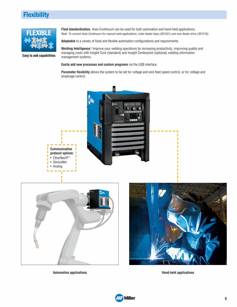
Flexibility
Fleet standardization. Auto-Continuum can be used for both automation and hand-held applications.Note: To convert Auto-Continuum for manual weld applications, order feeder base (301431) and wire feeder drive (301216).
Adaptable to a variety of fixed and flexible automation configurations and requirements.
Welding Intelligence.™ Improve your welding operations by increasing productivity, improving quality andmanaging costs with Insight Core (standard) and Insight Centerpoint (optional) welding informationmanagement systems.
Easily add new processes and custom programs via the USB interface.
Parameter flexibility allows the system to be set for voltage and wire feed speed control, or for voltage andamperage control.
Easy to add capabilities
FLEXIBLE
Automation applications Hand-held applications
Communication protocol options:• EtherNet/IP™
• DeviceNet • Analog
6
Auto-Continuum™ System Processes
Best for
Deposition
Gap Filing
Low Heat Input
Out-of-Position Welds
Low Spatter
Thick Metals
Thin Metals
Increased Travel Speed
Standard Spray
A
D
D
A
A
A
High-Deposition MIG
A
D
C
A
A
A
Accu-Pulse
A
B
B
A
A
A
B
A
Versa-Pulse
B
B
A
B
A
C
A
A
MIGShort Circuit
D
A
A
B
C
D
A
B
RMD
D
A
A
B
B
D
A
C
Ratings A, B, C, and D are relative values. An “A” rating indicates a best fit between your performance needs and process.A “blank” rating indicates that the process is not recommended for that application.
COLDHOT
Each weld program is designed for specific wire and gas combinations — for optimized performance.
Low spatter levels at high travel speeds is a requirement in automated welding. The Versa-Pulse process preciselycontrols the welding arc, significantly reducing spatter size and quantity. Total spatter can significantly reduced over traditional processes.
NEW! Versa-Pulse™
• Fast, low-heat, low-spatter process — for high-speed automation on materials 1/4 inch (6.35 mm) and thinner
• Great for gap filling• Shortest arc length/ lowest pulse voltage for lower heat and lower spatter
at higher speeds
Accu-Pulse®• The most popular process for majority of industrial welding applications• Most adaptive arc on 16 gauge (1.6 mm) and thicker• Designed for all weld positions
RMD®
• Lowest heat process, best for gap handling• Limited travel speed
High-deposition MIG• Higher deposition rates than standard spray transfer on thicker materials• Designed for welding applications in which spray transfer is preferred
MIG (short circuit)• Lower spatter than traditional MIG welders• Better arc performance with silicon bronze and coated materials
The adaptive arcs of Versa-Pulse™ andAccu-Pulse® instantly make adjustmentsto handle weld tacks, large gaps andinconsistent parts. The result is higherquality welds and fewer weld defects.
Better weld quality
ADAPTIVE ARC
FOR A CONSISTENT WELD
7
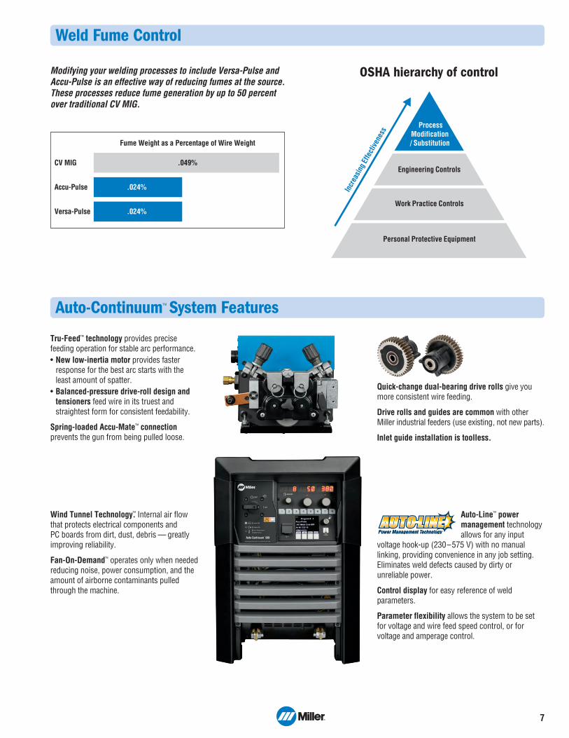
Weld Fume Control
Modifying your welding processes to include Versa-Pulse andAccu-Pulse is an effective way of reducing fumes at the source.These processes reduce fume generation by up to 50 percentover traditional CV MIG.
Fume Weight as a Percentage of Wire Weight
CV MIG .049%
Accu-Pulse .024%
Versa-Pulse .024%
Incr
easi
ng E
ffect
iven
ess Process
Modification/ Substitution
Engineering Controls
Work Practice Controls
Personal Protective Equipment
OSHA hierarchy of control
Auto-Continuum™ System Features
Quick-change dual-bearing drive rolls give you more consistent wire feeding.
Drive rolls and guides are common with other Miller industrial feeders (use existing, not new parts).
Inlet guide installation is toolless.
Tru-Feed™ technology provides precisefeeding operation for stable arc performance. • New low-inertia motor provides faster
response for the best arc starts with the least amount of spatter.
• Balanced-pressure drive-roll design andtensioners feed wire in its truest and straightest form for consistent feedability.
Spring-loaded Accu-Mate™ connectionprevents the gun from being pulled loose.
Auto-Line™ powermanagement technologyallows for any input
voltage hook-up (230–575 V) with no manuallinking, providing convenience in any job setting.Eliminates weld defects caused by dirty orunreliable power.
Control display for easy reference of weldparameters.
Parameter flexibility allows the system to be setfor voltage and wire feed speed control, or forvoltage and amperage control.
Wind Tunnel Technology™. Internal air flow that protects electrical components and PC boards from dirt, dust, debris — greatlyimproving reliability.
Fan-On-Demand™ operates only when neededreducing noise, power consumption, and theamount of airborne contaminants pulled through the machine.
8
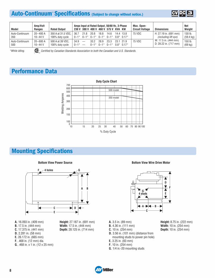
Duty Cycle Chart
Wel
ding
Am
pere
s
500600700
400
200
300
1000
150
% Duty Cycle
10 302015 25 40 50 7060 80 90 100
500 model
350 model
Performance Data
Certified by Canadian Standards Association to both the Canadian and U.S. Standards.
Model
Auto-Continuum350
Auto-Continuum500
Amp/VoltRanges
20–400 A10–44 V
20–600 A10–44 V
Rated Out put
350 A at 31.5 VDC,100% duty cycle
500 A at 39 VDC,100% duty cycle
Max. Open-Circuit Voltage
75 VDC
75 VDC
Amps Input at Rated Output, 50/60 Hz, 3-Phase230 V 380 V 400 V 460 V 575 V KVA KW
H: 27.19 in. (691 mm) (including lift eye)W: 17.5 in. (444 mm)D: 28.22 in. (717 mm)
Auto-Continuum™ Specifications (Subject to change without notice.)
*While idling.
EC D
A B
4 holes F G
A B
E
F
D
C
4 studsG
Bottom View Power Source Bottom View Wire Drive Motor
A. 16.093 in. (409 mm)B. 17.5 in. (444 mm)C. 17.375 in. (441 mm)D. 2.281 in. (58 mm)E. 26.172 in. (665 mm)F. .468 in. (12 mm) dia.G. .468 in. x 1 in. (12 x 25 mm)
Height: 27.187 in. (691 mm)Width: 17.5 in. (444 mm)Depth: 28.125 in. (714 mm)
A. 3.5 in. (89 mm)B. 4.36 in. (111 mm)C. 10 in. (254 mm)D. 3.56 in. (101 mm) (distance from mounting studs to power pin hole)E. 3.25 in. (83 mm)F. 10 in. (254 mm)G. 1/4 in.-20 mounting studs
Height: 8.75 in. (222 mm)Width: 10 in. (254 mm)Depth: 10 in. (254 mm)
Mounting Specifications
9
Drive Roll Kits and Guides (Order from Miller Service Parts.)
Wire Size .035 in. (0.9 mm) 151026 — 151052 — 265255.040 in. (1.0 mm) 161190 — — — —.045 in. (1.1/1.2 mm) 151027 151037* 151053 151070 265256*.052 in. (1.3/1.4 mm) 151028 — 151054 — —1/16 in. (1.6 mm) 151029 151039 151055 151072 265257.068/.072 in. (1.8 mm) — — 151056 — —5/64 in. (2.0 mm) — — 151057 — —3/32 in. (2.4 mm) — 151041 151058 — —
Select drive roll kits from chart below according to type and wire size being used. Drive roll kits include four drive rolls, necessary guides and feature an anti-wear sleeve for inlet guide.
*Accommodates .045- and .047-inch (3/64-inch) wire.
“V” groove for hard wire
“U” groove forsoft wire or soft-shelledcored wires
“U” groove foraluminum
wires containsnylon guides
“V” knurled forhard-shelled cored wires
“U” cogged for extremely soft
wire or soft-shelledcored wires (i.e., hard facing types)
Wire Size Inlet Guide Intermediate Guide.035 in. (0.9 mm) 221912 242417.047 in. (1.2 mm) 221912 2059361/16 in. (1.6 mm) 221912 205937
Nylon Wire Guides for Feeding Aluminum Wire
Note: “U” groove drive rolls are recommended when feeding aluminum wire.
Wire Size Inlet Guide Intermediate Guide.023–.040 in. (0.6–1.0 mm) 221030 149518.045–.052 in. (1.1–1.4 mm) 221030 1495191/16–5/64 in. (1.6–2.0 mm) 221030 1495203/32–7/64 in. (2.4–2.8 mm) 229919 149521
Wire Guides
Auto-Continuum™ Wire Drive Motor Assembly 301207 Left-hand drive301208 Right-hand drive
Wire Drive Motor Assembly Specifications (Subject to change without notice.)
Certified by Canadian Standards Association to both the Canadian and U.S. Standards.
Wire Feed Speed
Standard50–1,000 ipm (1.27–25.4 m/min.)
Input WeldingCircuit Rating
500 A at 100% duty cycle
NetWeight
16.5 lb. (7.5 kg)
Dimensions
H: 8.75 in. (222 mm)W: 10 in. (254 mm)D: 10 in. (254 mm)
InputPower
50 VDC
WireDiameterCapacity
.035–5/64 in.(0.9–2.0 mm)
WeldingPowerSource
Auto-Continuum 350 or 500
10
Genuine Miller® Accessories
Consulting Services
Field Application Support 195480Auto-Continuum™ systems may requirefactory-trained technical support, dependingon the complexity of the application and the local availability and capability ofqualified welding engineers or technologyexperts. Contact the factory with questions. Factory support is available at a flat rate of$1,250.00 per day (plus expenses) whenscheduled more than 10 days in advance.With less than 10-day notice, rates may behigher. Rates are based on a 10-hour day,including travel. One day minimum.
Auto-Continuum with DeviceNet
DeviceNet Communication Cables 300020 9 ft. (2.7 m)300021 20 ft. (6.1 m)
Auto-Continuum Digital Peripheral Cable 301104 20 ft. (6.1 m)
Auto-Continuum Analog
Analog Receptacle Kits194793 ABB®
194791 FANUC®
194790 Motoman®
300056 Panasonic®
195002 UniversalOne required per machine. 12-inch (305 mm)length. For analog communication with robotcontrols via 72-pin Harting connector on Auto-Continuum.
DeviceNet to Analog Adapter 301427 FieldAdapts DeviceNet to analog communication.
Analog Robot Simulator 195030Device simulates the analog commands oftypical robots. It can be used as a diagnostictool to determine power source functionality andisolate robot, power source or cable issues.
For All Auto-Continuum Models
ADAM DI/O Module 300803Provides a digital I/O interfacefor communication between arobot /PLC and Auto-Continuumpower supply. The interfaceallows for the interaction of arobot or PLC and the InsightCenterpoint™ application. Thismodule is required for all
DeviceNet and analog Auto-Continuum modelsto run Insight Centerpoint.
Continuum Sourcing I/O Kit 301150
Wire Drive Motor Mounting Brackets300013 Universal – FANUC®/KUKA®/Motoman®
Welding Guns Manual — see BernardWelds.comAutomation — see Tregaskiss.com
Motor Control Cables 263368025 25 ft. (7.6 m)263368050 50 ft. (15.2 m)263368080 80 ft. (24.4 m)263368100 100 ft. (30.5 m)Includes overmolded connections on high-flexcables for optimal service life.
Volt-Sense Cable 242212050Replacement 50 ft. (15.2 m) cable. One cablesupplied with Auto-Continuum power source.
Ethernet Cables 300734 9.8 ft. (3 m)300735 16.4 ft. (5 m)300736 32.8 ft. (10 m)Industrial-grade 360-degree-shielded Cat 5Ethernet cable with conventional RJ45overmolded four-pole connector on one end to connect to factory network, and industrialM12 overmolded connector on the other end to attach to Auto-Continuum power source. Cable supports 10/100 Mbits-per-secondtransmission rate.
Auto-Continuum Robotic MIG Kit 301422Includes Auto-Continuum wire drive motor assembly (left-hand drive), flowmeter regulatorwith 50-foot (15.2 m) gas hose, two 50-foot(15.2 m) 4/0 weld cables with lugs, one motorcontrol cable, one 16.4-foot (5 m) Ethernetcable, .035/.045-inch V-groove drive roll kit with four drive rolls and necessary guides, and 30-foot (9 m) conduit assembly with quick disconnects.
Continuum Feeder Base and Spool Support301431Sheet metal construction. Allows mounting of Auto-Continuum wire drive motor for manualwelding operations.
Wire Feeder Drive (Left) 301216Use with feeder base and spool support whenconverting to a manual weld system.
Hub and SpindleAssembly 072094
Spindle Support092989
Spool Cover 057607
Wire Reel Assembly 108008
Reel Cover 195412For 60-pound (27 kg) coil. Helps to protect thewelding wire from dust and other contaminants.
Wire Straightener 141580 For .035–.045 in.(0.9–1.1 mm) wire.141581 For 1/16–1/8 in.(1.6–3.2 mm) wire.
Helps reduce the cast in wire to improve wirefeeding performance and increase the servicelife of the gun liner and contact tip.
Coolant Systems
Continuum Cooler 301214For use with water-cooled torches rated up to500 amps. Integrated coolant flow switchensures coolant is flowing in the system. TheContinuum cooler mounts to the bottom of theContinuum power source. Power is supplied viaan internal connection with the power source.
Low-Conductivity Coolant 043810Sold in cases of four one-gallon recyclable plasticbottles. Miller coolants contain a base of ethyleneglycol and deionized water to protect againstfreezing to -37 degrees Fahrenheit (-38˚C) orboiling to 227 degrees Fahrenheit (108˚C). Alsocontains a compound that resists algae growth.
Spindlesupport
Hub andspindleassembly
11
Typical Installations (Robotic/automation pulsed MIG or conventional MIG.)
Motor control cable(see page 10)
Included with robotic MIG kit.
Electrode cable*Must be ordered separately.
Work cable*Must be ordered separately.
Drum of wire
50 ft. volt-sense cable(see page 10)
Included with power source.
+ –
EtherNet/IProbot
controller
Analogrobot
controller
DeviceNetrobot
controller
1
3
54
2a
2b
2c
Ethernet cable
DeviceNetcommunication cable
DeviceNetcommunication cable
DeviceNet toanalog adapter
Analog receptacle kit
*For available lengths visitMillerWelds.com/equiptoweld.
Auto-Continuum Robotic MIG Kit 301422Kit includes the following:• Auto-Continuum wire drive motor assembly (left-hand drive)• Flowmeter regulator with 50-foot (15.2 m) gas hose• Two 50-foot (15.2 m) 4/0 weld cables with lugs• One motor control cable• One 16.4-foot (5 m) Ethernet cable• .035/.045-inch V-groove drive roll kit with four drive rolls and
necessary guides• 30-foot (9 m) conduit assembly with quick disconnects
1
2
3
4
5
Power SourceSee page 12 for available models. Choose power source accordingto preferred communication protocol. Each power source includes a 50-foot (15.2 m) volt-sense cable.
included with Auto-Continuum robotic MIG kit. See page 10 forindividual cables.
DeviceNet — Requires DeviceNet communication cable. See page 10 for available cable lengths.
Analog — Requires DeviceNet communication cable. See page 10 for available cable lengths. Also requires DeviceNet to analog adapter (301427) and analog receptacle kit(see page 10).
Auto-Continuum Robotic MIG KitIncludes wire drive assembly and all cables, hoses and hardware for outfitting a robot arm. See description at right for details.
Motor Mounting BracketSee page 10 for available brackets. Motor mounting brackets from other brands must be supplied by robot manufacturer orsystem integrator.
Tregaskiss Robotic MIG GunMust be ordered separately. Visit Tregaskiss.com for additional torch information.
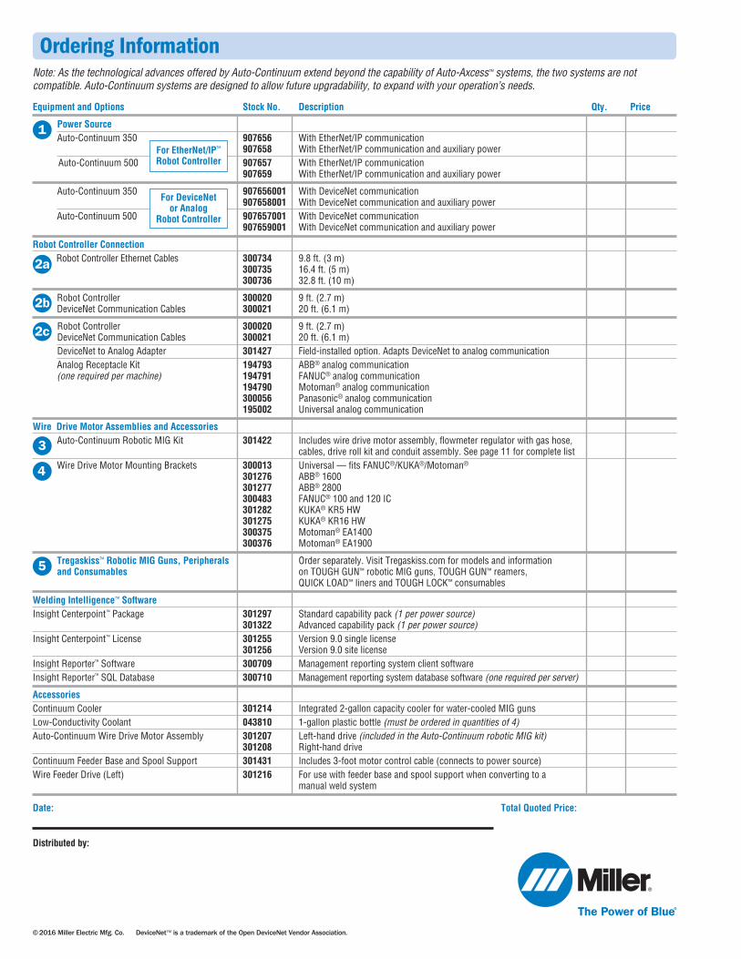
Equipment and Options Stock No. Description Qty. Price
Power Source Auto-Continuum 350 907656 With EtherNet/IP communication 907658 With EtherNet/IP communication and auxiliary powerAuto-Continuum 500 907657 With EtherNet/IP communication
907659 With EtherNet/IP communication and auxiliary power
Auto-Continuum 350 907656001 With DeviceNet communication 907658001 With DeviceNet communication and auxiliary powerAuto-Continuum 500 907657001 With DeviceNet communication
907659001 With DeviceNet communication and auxiliary power
Robot Controller Connection Robot Controller Ethernet Cables 300734 9.8 ft. (3 m) 300735 16.4 ft. (5 m)
300736 32.8 ft. (10 m)
Robot Controller 300020 9 ft. (2.7 m)DeviceNet Communication Cables 300021 20 ft. (6.1 m)
Robot Controller 300020 9 ft. (2.7 m)DeviceNet Communication Cables 300021 20 ft. (6.1 m)DeviceNet to Analog Adapter 301427 Field-installed option. Adapts DeviceNet to analog communicationAnalog Receptacle Kit 194793 ABB® analog communication(one required per machine) 194791 FANUC® analog communication
194790 Motoman® analog communication 300056 Panasonic® analog communication 195002 Universal analog communication
Wire Drive Motor Assemblies and AccessoriesAuto-Continuum Robotic MIG Kit 301422 Includes wire drive motor assembly, flowmeter regulator with gas hose,
cables, drive roll kit and conduit assembly. See page 11 for complete listWire Drive Motor Mounting Brackets 300013 Universal — fits FANUC®/KUKA®/Motoman®
Tregaskiss™ Robotic MIG Guns, Peripherals Order separately. Visit Tregaskiss.com for models and information and Consumables on TOUGH GUN™ robotic MIG guns, TOUGH GUN™ reamers,
QUICK LOAD™ liners and TOUGH LOCK™ consumables
Welding Intelligence™ SoftwareInsight Centerpoint™ Package 301297 Standard capability pack (1 per power source) 301322 Advanced capability pack (1 per power source)Insight Centerpoint™ License 301255 Version 9.0 single license 301256 Version 9.0 site licenseInsight Reporter™ Software 300709 Management reporting system client softwareInsight Reporter™ SQL Database 300710 Management reporting system database software (one required per server)
AccessoriesContinuum Cooler 301214 Integrated 2-gallon capacity cooler for water-cooled MIG gunsLow-Conductivity Coolant 043810 1-gallon plastic bottle (must be ordered in quantities of 4)Auto-Continuum Wire Drive Motor Assembly 301207 Left-hand drive (included in the Auto-Continuum robotic MIG kit) 301208 Right-hand driveContinuum Feeder Base and Spool Support 301431 Includes 3-foot motor control cable (connects to power source) Wire Feeder Drive (Left) 301216 For use with feeder base and spool support when converting to a manual weld system
Date: Total Quoted Price:
Note: As the technological advances offered by Auto-Continuum extend beyond the capability of Auto-Axcess™ systems, the two systems are notcompatible. Auto-Continuum systems are designed to allow future upgradability, to expand with your operation’s needs.