AutoCAD Tutorial - Simple house layout This tutorial will quickly show you how to use the AutoCAD software. The tutorial will demonstrate the various tools that you can use while designing a simple house layout. Please take note that there is more then one way to design a house and that every tool has more then one function. This tutorial will show you the basic steps that will allow you to design a house, a car or even computer components with a very high degree of quality and precision. The first step is to make sure that you screen is set to true colors. To do so, minimize you screen and on the desktop right click your mouse. Select properties, then settings. Change your color quality to “true color”. Click apply and then OK. To start AutoCAD: Start > Program > Cross Curricular > AutoCAD … > AutoCAD … If the Active Assistance window is open, turn off this feature by right-clicking on the red-plus symbol on the status bar next to the clock and click on “Exit”. You are now ready to start using AutoCAD. Here is what your screen will look like at first. On the top section you will find the usual MENU bar that most of you are familiar with: File, Edit, View, Insert etc… Directly under that you will find some icons, again some of these will be document.doc Page 1 of 45
Transcript
AutoCAD Tutorial - Simple house layout
This tutorial will quickly show you how to use the AutoCAD software. The tutorial will demonstrate the various tools that you can use while designing a simple house layout. Please take note that there is more then one way to design a house and that every tool has more then one function. This tutorial will show you the basic steps that will allow you to design a house, a car or even computer components with a very high degree of quality and precision.
The first step is to make sure that you screen is set to true colors. To do so, minimize you screen and on the desktop right click your mouse. Select properties, then settings. Change your color quality to “true color”. Click apply and then OK.
To start AutoCAD: Start > Program > Cross Curricular > AutoCAD … > AutoCAD …
If the Active Assistance window is open, turn off this feature by right-clicking on the
red-plus symbol on the status bar next to the clock and click on “Exit”.
You are now ready to start using AutoCAD. Here is what your screen will look like at first.
On the top section you will find the usual MENU bar that most of you are familiar with: File, Edit, View, Insert etc… Directly under that you will find some icons, again some of these will be familiar. When you bring your cursor on to the icon and leave it on for a second, a pop up will display the name and function of this tool.
I would like to bring your attention to the last section of icon on the first row which is called the STANDARD toolbar
Starting with the icon that looks like a hand, this is called the “Pan Realtime” tool. This tool allows you to move your drawing in any direction on you screen.
The second icon is called “Zoom Realtime”. This one allows you to zoom in and out of your drawing simply by selecting it and then moving your mouse up and down on your screen while pressing on the left button.
document.doc Page 1 of 36
AutoCAD Tutorial - Simple house layout
The third one is called the “Zoom Window” This will be your most useful zoom. Once selected all you will need to do is create a small window (also called marquise) around the area you need a better view of and voila.
The fourth one is called “Zoom Previous” . Like the name states, simply be clicking on this tool to screen will go back to the previous zoom setting. Very useful to use right after
using the “Zoom Window” function.
The two vertical toolbars located on the left hand side of your screen are the two most important toolbars that you will need in AutoCAD. Once you have learned to master the tools on these toolbars you have mastered AutoCAD. We will start be giving you a brief description of the most important tools on each.
The first toolbar is called the DRAW toolbar
The “Line” tool will allow you to draw lines in any direction.
The “Arc” tool will allow you to create arcs all the way up to 360 degrees
The “Circle” tool will allow you to create circles using either the radius or diameter.
Now the second tool bar. This one is called the MODIFY toolbar
The “Mirror” tool. This one allows you to recreate a mirror image of an object following a specific mirror line. This tool is very useful when creating objects that are the same left to right.
The “Offset” tool. This one allows you to offset which means recreate a line or on object at a specified distance.
The “Array” tool. This tool allows you to recreate a line or an object many time at a specified distance in one simple step.
The “Move” tool. This tool allows you to move a line or an object to an exact location
The “Rotate” tool allows you to rotate a line or an object to an exact degree
The “Scale” tool allows you to enlarge or reduce the size of a drawing.
The “Stretch” tool allows you to stretch just a section of a drawing.
The “Trim” tool allows you to trim line(s) to an exact intersection.
The “Extend” tool allows you to extend line(s) to an outer object.
The “Fillet” tool allows you to join two line with an arc of various radius, note that a radius of 0 gives you a right angle.
I know that this has been a lot of reading but believe me, once you have mastered these 12 simple tools, using AutoCAD will be as easy as putting jam on your toast.
document.doc Page 2 of 36
AutoCAD Tutorial - Simple house layout
Let’s get started.
Make sure that POLAR and OSNAP are on (depressed). These two buttons are located side by side at the bottom of your screen. OSNAP stands for OBJECT SNAP it allows you to start a new line at a specific point. POLAR allows you to draw straight lines by temporarily freezing your object line when it crosses one of the four polar.
Hold your mouse over OSNAP, right click and select setting. This menu should pop up. Select the same boxes as on the picture below.
Click OK.
You will notice that when we first start drawing our house that our lines will be much longer then our screen allows, that is normal. I will show you later how to resolve that situation.
Select the line tool Click on the lower left corner of your working screen Point your mouse in the direction that you want to draw you line (in this case to your
right) Once the line is straight let go of the mouse Type in the length of your line (don’t need to move the mouse, just type 10 000) and
press Enter. Note that AutoCAD uses units, for now the software doesn’t know if you are using cm. or inches.
Press Esc to end the line command Press Enter. AutoCAD will bring you back to the last command that you have used, in
this case the line tool Select the left end point of your first line Point the mouse in the vertical direction Now type in 8 000 and press Enter. Press Esc to end the line command.
document.doc Page 3 of 36
AutoCAD Tutorial - Simple house layout
We now have the two lines that represent the total dimensions of our house. As you have noticed they are much longer then our screen. To view the whole house, select View from the menu bar. Now select Zoom followed by Extents. This will reset your drawing limits to the lines you have just drawn.
Once your drawing is to the right scale complete the outside wall of your house. Remember, your house is 10 000 mm across and 8 000 mm deep. Once completed your drawing should look like the following.
SAVE
document.doc Page 4 of 36
AutoCAD Tutorial - Simple house layout
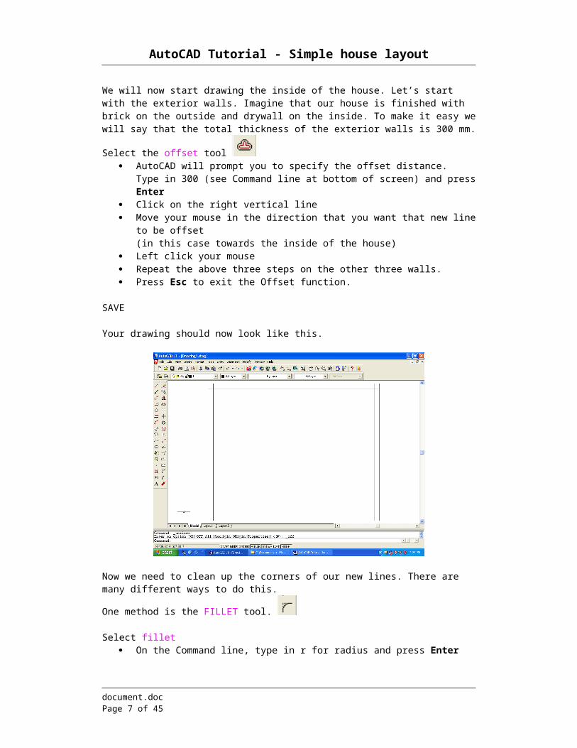
We will now start drawing the inside of the house. Let’s start with the exterior walls. Imagine that our house is finished with brick on the outside and drywall on the inside. To make it easy we will say that the total thickness of the exterior walls is 300 mm.
Select the offset tool AutoCAD will prompt you to specify the offset distance.
Type in 300 (see Command line at bottom of screen) and press Enter Click on the right vertical line Move your mouse in the direction that you want that new line to be offset
(in this case towards the inside of the house) Left click your mouse Repeat the above three steps on the other three walls. Press Esc to exit the Offset function.
SAVE
Your drawing should now look like this.
Now we need to clean up the corners of our new lines. There are many different ways to do this.
One method is the FILLET tool.
Select fillet On the Command line, type in r for radius and press Enter Type in 0 (this will create a corner with a radius of 0 degrees therefore a right angle) and
press Enter Select a vertical line that you have just offset Now select a horizontal line that you have just offset
document.doc Page 5 of 36
AutoCAD Tutorial - Simple house layout
Your drawing should now look like this (I did mine on the bottom right-hand corner).
Notice that the two lines are now joined perfectly. Repeat the same process for the other three corners. Note: Make sure that you always select the line segment you want to keep, otherwise AutoCAD will trim the wrong section of the line.
SAVE your work after every successful step.
document.doc Page 6 of 36
AutoCAD Tutorial - Simple house layout
Drawing the walls for the inside of the house.
Draw two lines in the center of our house, one vertically and one horizontally.
Select the line tool Move your mouse towards the midpoint of the vertical line (inside rectangle) Left click Move the mouse perpendicular to the other side Left click
Notice that the midpoint and the perpendicular point were selected for you. That is what the midpoint feature of OSNAP tool does for you.
Repeat by drawing a line in the center vertically
Inside walls are not as thick as your outside walls. The OFFSET for all of the inside walls is 200 mm. Since we want these two walls to be exactly in the center we will offset them by 100 mm on each side of the center lines.
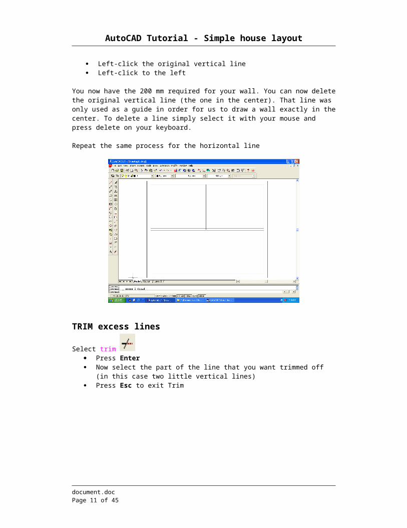
Select offset Type in 100 in the Command Line and press Enter Left-click the vertical line Left-click to the right Left-click the original vertical line Left-click to the left
You now have the 200 mm required for your wall. You can now delete the original vertical line (the one in the center). That line was only used as a guide in order for us to draw a wall exactly in the center. To delete a line simply select it with your mouse and press delete on your keyboard.
Repeat the same process for the horizontal line
document.doc Page 7 of 36
AutoCAD Tutorial - Simple house layout
TRIM excess lines
Select trim Press Enter Now select the part of the line that you want trimmed off (in this case two little vertical
lines) Press Esc to exit Trim
document.doc Page 8 of 36
AutoCAD Tutorial - Simple house layout
LayersIn order to make our drawing more user friendly we will create what is called layers. The toolbar located directly below the standard toolbar is called OBJECT PROPERTIES toolbar.
This is the toolbar that will use in order to create new layers.
Select layers (second icon on the OBJECT PROPERTIES toolbar) New Name the new layer “outside wall” Select the color and choose blue Ok New again Follow the same process and create the following layers Inside wall (green) Doors (red) Stairs (magenta) When completed click OK
document.doc Page 9 of 36
AutoCAD Tutorial - Simple house layout
You may now change the lines on you drawing to it’s proper layer. To do so select the 5 lines that represent your inside walls. Once selected, left click on the
dropdown menu on your OBJECT PROPERTIES toolbar and select “inside wall”. Your lines should now have turned green.
Press Escape Repeat for your outside wall
SAVE your successes.
document.doc Page 10 of 36
AutoCAD Tutorial - Simple house layout
Doors.
You probably noticed that our rooms didn’t have any doors, which makes them pretty useless.
Select offset Type in 150 on the Command line and press Enter Select the right vertical line on the central wall Offset to the right Press Esc. Select offset again Type in 750 on the Command line and press Enter Select that new vertical line that you have just created Offset to the right again Press Esc.
By using the offset tool you have just created the guidelines that we will use in the construction of a door. The door will be 150 mm from the wall and that the door opening will be 750 mm wide.
To extend a line to the next wall:
Select the Extend tool Press Enter Click on one of the new lines near the central horizontal wall. It will extend to the other
wall. Repeat for the other line. SAVE
document.doc Page 11 of 36
AutoCAD Tutorial - Simple house layout
Select trim Press Enter Trim the excess
Now trim the line in-between your door opening
document.doc Page 12 of 36
AutoCAD Tutorial - Simple house layout
Door JamIn order to properly see our door jam we will use our zoom window tool. This will allow us to work with far more precision.
Select your Zoom Window (standard toolbar) Create a window with your mouse.
The window you create will become the size of your screen.
This is what you should now see on your screen.
Select offset Type in 30 on the Command line and press Enter Select all three lines on the left side of you door and offset them to the outside. It should
now look like this.
document.doc Page 13 of 36
AutoCAD Tutorial - Simple house layout
Now offset that new vertical line one more time to the inside of the door by 30mm.
Now offset the original vertical line to the inside of the wall by 70 mm.
document.doc Page 14 of 36
AutoCAD Tutorial - Simple house layout
One more guideline is required. Using the Line Draw tool , draw a horizontal line to cut across the center of the vertical lines.
In order to make things easier to see let’s change all the new lines that we have just create into their proper layer. Select the six new lines and assign them to the door layer.
NOTE: You can Undo (the undo button, Edit > Undo or Ctrl-Z) at any point during the next few steps.
document.doc Page 15 of 36
AutoCAD Tutorial - Simple house layout
In order to create the door jam we will need to connect all these new line at strategic places. The best way to do this will be to use the FILLET tool.
Select FILLET Type R and press Enter Type 0 (zero) and press Enter Select the bottom horizontal line (red) Select the outside vertical line (red)
Press Enter select the top horizontal line (red) select the first outside vertical line (red) Press Enter
document.doc Page 16 of 36
AutoCAD Tutorial - Simple house layout
Select the top horizontal line again (remember to click on the part of the line that you what to keep)
Select the red vertical line inside your wall Press Enter
Repeat for the bottom line
document.doc Page 17 of 36
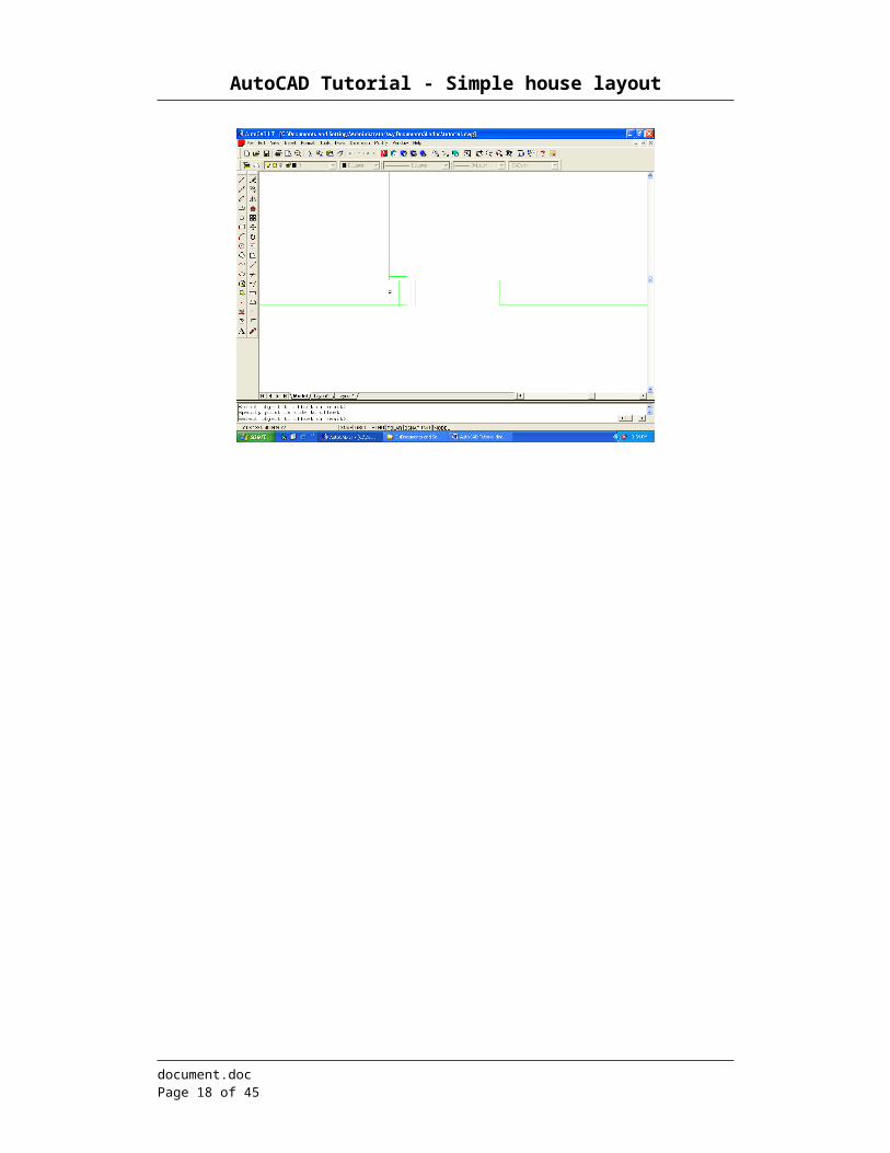
AutoCAD Tutorial - Simple house layout
Press enter now select the horizontal middle line select the first red line (the first one to be offset)
Press enter select the small section that you want to keep of the horizontal line select the section that you want to keep of the vertical line
document.doc Page 18 of 36
AutoCAD Tutorial - Simple house layout
Now trim the part of the door jam that cuts through your wall
Select trim select the line you want to trim and the two lines you want to trim from Press enter Select the part of the line that you want trimmed
REMEMBER: you can always correct your work by undoing the last several instructions.
SAVE
Congratulations you have now completed a door jam. As you know practice makes perfect, therefore follow the same steps in order to create the door jam on the other side.
Your drawing should look like this.
document.doc Page 19 of 36
AutoCAD Tutorial - Simple house layout
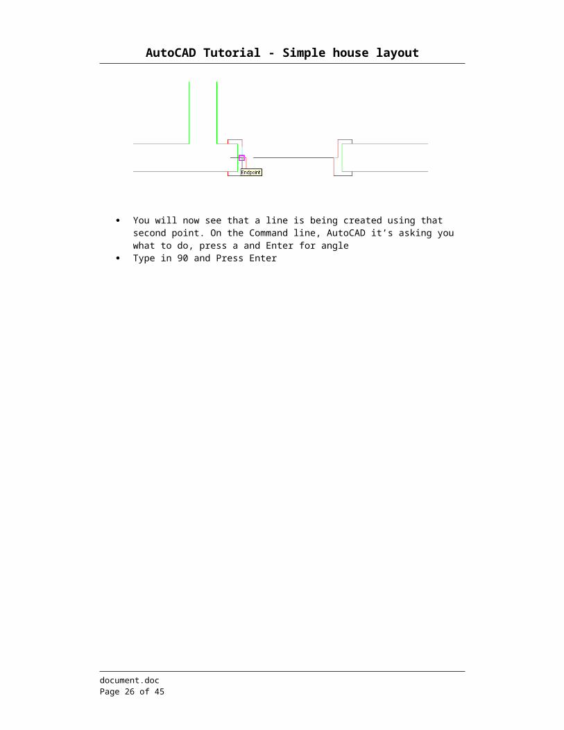
We will now create an arc that will represent our door and the trajectory that it will follow when we use it. Doors always swing to the nearest. We will start the door on the door jam farthest from the wall.
Select the arc tool Select the endpoint like the following picture
AutoCAD will prompt you, on the Command line at the bottom of the screen, to find if you want the other end to be the center or the end of the arc. Press c and Enter for center
Select the center of the door jam nearest the wall for your second point
You will now see that a line is being created using that second point. On the Command line, AutoCAD it’s asking you what to do, press a and Enter for angle
Type in 90 and Press Enter
document.doc Page 20 of 36
AutoCAD Tutorial - Simple house layout
Now select the line tool Draw a line from the middle of the arc (second point from earlier) to the end of the arc SAVE
Now let’s create a door for that second room. Since our doors are the same size drawing them again would be a waste of time. We will use our mirror tool. Before we can do this use your “pan realtime” tool and move your drawing on your screen in order to properly see both sides of you dividing wall.
Create a line inside your vertical wall. That line will later be used as a reference point.
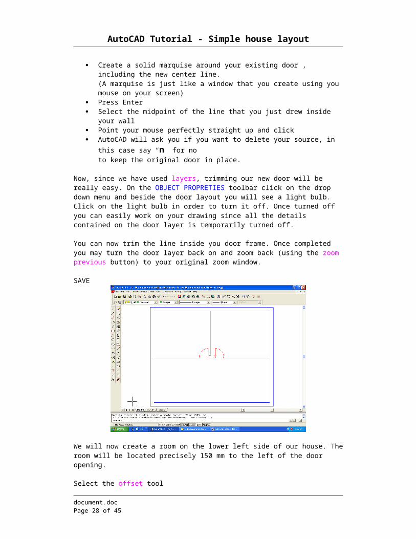
Now select your mirror tool Create a solid marquise around your existing door , including the new center line.
(A marquise is just like a window that you create using you mouse on your screen) Press Enter Select the midpoint of the line that you just drew inside your wall Point your mouse perfectly straight up and click AutoCAD will ask you if you want to delete your source, in this case say “n” for no
to keep the original door in place.
Now, since we have used layers, trimming our new door will be really easy. On the OBJECT PROPRETIES toolbar click on the drop down menu and beside the door layout you will see a light
document.doc Page 21 of 36
AutoCAD Tutorial - Simple house layout
bulb. Click on the light bulb in order to turn it off. Once turned off you can easily work on your drawing since all the details contained on the door layer is temporarily turned off.
You can now trim the line inside you door frame. Once completed you may turn the door layer back on and zoom back (using the zoom previous button) to your original zoom window.
SAVE
We will now create a room on the lower left side of our house. The room will be located precisely 150 mm to the left of the door opening.
Select the offset tool Type in 150 and press Enter Select the inside line of the door frame (see picture below)
Offset to the left of the door frame
document.doc Page 22 of 36
AutoCAD Tutorial - Simple house layout
Now we will offset that new line by 200 mm. This will represent the thickness of our wall.
Select the offset tool Type in 200 and press Enter Offset to the left of that new line
We will now extend those two new lines all the way down to the exterior wall.
Select the Extend” tool Press Enter Click close to the bottom-end of one the new lines. It should extend to the bottom wall. Repeat for the other line
You may now trim the two lines that extend into the inside wall.
document.doc Page 23 of 36
AutoCAD Tutorial - Simple house layout
SAVE
We need a door on this new room. Since we already have a door, we will copy the one that we have.
Select the left door (including door frame) using a solid marquise Control C for copy Control V for paste Now paste that new door anywhere in the open foyer by clicking the left button on your
mouse
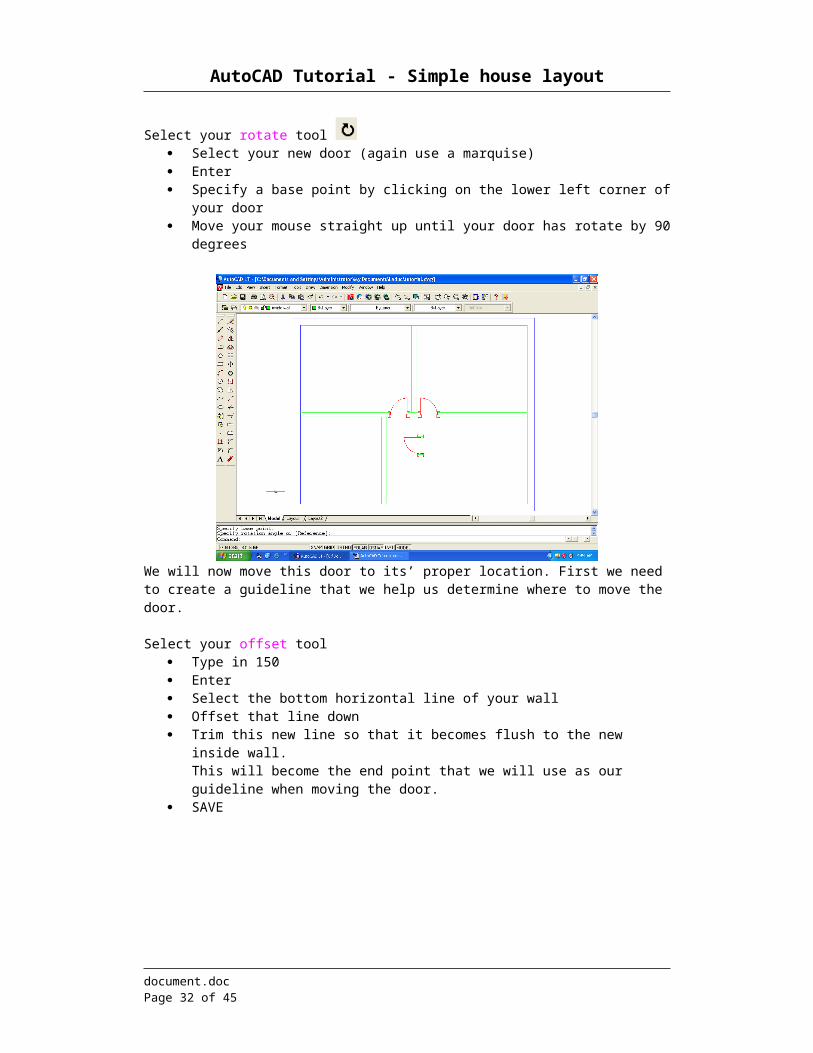
Now that we have our door we will need to rotate it.
Select your rotate tool Select your new door (again use a marquise) Enter Specify a base point by clicking on the lower left corner of your door Move your mouse straight up until your door has rotate by 90 degrees
document.doc Page 24 of 36
AutoCAD Tutorial - Simple house layout
We will now move this door to its’ proper location. First we need to create a guideline that we help us determine where to move the door.
Select your offset tool Type in 150 Enter Select the bottom horizontal line of your wall Offset that line down Trim this new line so that it becomes flush to the new inside wall.
This will become the end point that we will use as our guideline when moving the door. SAVE
Select the move tool Marquis the whole door, then press Enter Using the zoom window zoom unto your door (this will allow you to properly select your
displacement point)
document.doc Page 25 of 36
AutoCAD Tutorial - Simple house layout
Select the following point
Click on Zoom Previous in order to see your full screen Move your mouse over the end point of your guideline and left click. That will become
your second point of displacement SAVE
Once your new door is in place you may delete / trim the unnecessary lines. Your drawing should now look like this.
document.doc Page 26 of 36
AutoCAD Tutorial - Simple house layout
Have you SAVEd recently?
document.doc Page 27 of 36
AutoCAD Tutorial - Simple house layout
StairsWe have now completed the divisions inside our upper floor. Now we will add a set of stair that will allow us to go down to our main floor.
Select your offset tool Type in 1000 Enter Select the inside line of your right exterior wall Offset that line to the left Repeat the same for the inside line of your lower exterior wall
Select those two new lines and place them under your “stair” layer.
These new lines will become the guidelines for the construction of your stairs.
The standard width for stairs is 1000 mm, the standard depth for a step is 220 mm.
I will now show you how to recreate a line or an object many times at a specific distance.
Select the array tool Click on the “select objects” button Select the horizontal line (the new line) Enter Modify your submenu like the following
document.doc Page 28 of 36
AutoCAD Tutorial - Simple house layout
Now let’s take a look at what we have done. Array works the same way as the offset tool. The only difference is that it allows you to repeat the same steps many times in a row. Imagine a spreadsheet, on a spreadsheet you find rows and columns. The rows move from the top to the bottom of your page and the columns move across from your left to your right.
That means that we have just ask AutoCAD to create 12 rows and 1 column (it has to be at least one, 0 would mean that there is no object). Since we are now working with rows, under row offset enter the offset that we would like to have between each object (note that a positive offset move your lines up vs. a negative offset would move your lines down). Column offset stays at 1 because we are not working with the columns yet.
Click on preview
If your drawing looks like the one above click on “accept”, if not click on “modify” and double check your inputs.
document.doc Page 29 of 36
AutoCAD Tutorial - Simple house layout
Now select your trim tool select all your lines (using an open marquise -create a window from right to left) Press enter trim of all extra lines SAVE
Repeat the same process for the vertical lines. Remember that this time it will be columns instead of rows. You will need 8 columns to complete your stairs.
You may now trim your guideline like the picture above.
document.doc Page 30 of 36
AutoCAD Tutorial - Simple house layout
We are now ready to create the handrail. A typical handrail is 100 mm wide.
Select your offset tool type in 100 and press Enter select the vertical guideline for the inside of the stairs and offset it to the left select the horizontal guideline and offset it up SAVE
Now that we have our guidelines for the handrail we will use our fillet tool to join them together.
Select your fillet tool type in “r” (in order to change your radius) and press Enter type in 100 and Press Enter now select the two exterior guidelines
(remember, your fillet tool will join the part of the line that you select and delete the rest, so click on the part of the line that you want to keep)
repeat for the interior guidelines SAVE
We will now create an end to the handrail.
document.doc Page 31 of 36
AutoCAD Tutorial - Simple house layout
Zoom in on the lower end of the handrail
Select your arc tool your start point will be the upper guideline
Type in “e” for your second endpoint. We want the arc to complete its’ radius exactly at the endpoint of the second guideline.
Press Enter Select the second guideline endpoint
document.doc Page 32 of 36
AutoCAD Tutorial - Simple house layout
Type in “d” for direction. We will specify the direction that we want our arc to follow. Press Enter Now point your mouse at the left side of the handrail and left click Press
document.doc Page 33 of 36
AutoCAD Tutorial - Simple house layout
We now need to create a door in the foyer of our house. The front door of a house is wider than the doors inside. Just to add a little style, we will install a set of French doors in the middle of our front wall. A standard door is 900 mm wide. In our case we will create an opening of 1800 mm since we are installing French doors.
Make sure you’re on the exterior wall layer at the bottom of the screen.Select your line tool
Draw a line in the center of your bottom exterior wallSelect your offset tool
Offset that line 900 mm., left and rightSelect your trim tool
Trim your lines in between the new opening for your French doors except the centeral vertical line. We will remove it later.
SAVE
Now that the opening for your French door is created, draw the two doors that will go inside. Remember that all you need to do is to create the one side and then mirror that side in order to create the second door. Don’t be afraid to go back to page 13 for the instructions on how to create a door. (Try to copy and paste the door jams you need.
When completed, trim away the central vertical line.
When your done your drawing should look like the following;
document.doc Page 34 of 36
AutoCAD Tutorial - Simple house layout
SAVE
Adding TextThe house is almost completed. The next step is to add text to our layout. By adding text our layout will become easier to understand.
Under your Menu bar select Draw Text Single line text Click inside the upper left room Type in 200 for your text height (same as your wall thickness) Type in 0 for you text rotation Type in “Bedroom 1” Enter Now click inside the room to its’ right Type in “Bedroom 2” Enter Now click in the lower room Type in “Office” Enter Now click in the main lobby Type in “Foyer” Enter Enter SAVE
document.doc Page 35 of 36
AutoCAD Tutorial - Simple house layout
Congratulations, your house layout is now completed. You know have the necessary knowledge to properly use the AutoCAD software. Now if you have time you may want to add some furniture to your house. Have fun and remember to always be as precise as possible.