4
AUTOCAR Team #13 Greg Futia Greg VonFange Phil Kasper Ani Bhende
| Date post: | 30-Dec-2015 |
| Category: |
Documents |
| Upload: | kirby-robbins |
| View: | 29 times |
| Download: | 0 times |

AUTOCAR
Team #13
Greg Futia
Greg VonFange
Phil Kasper
Ani Bhende
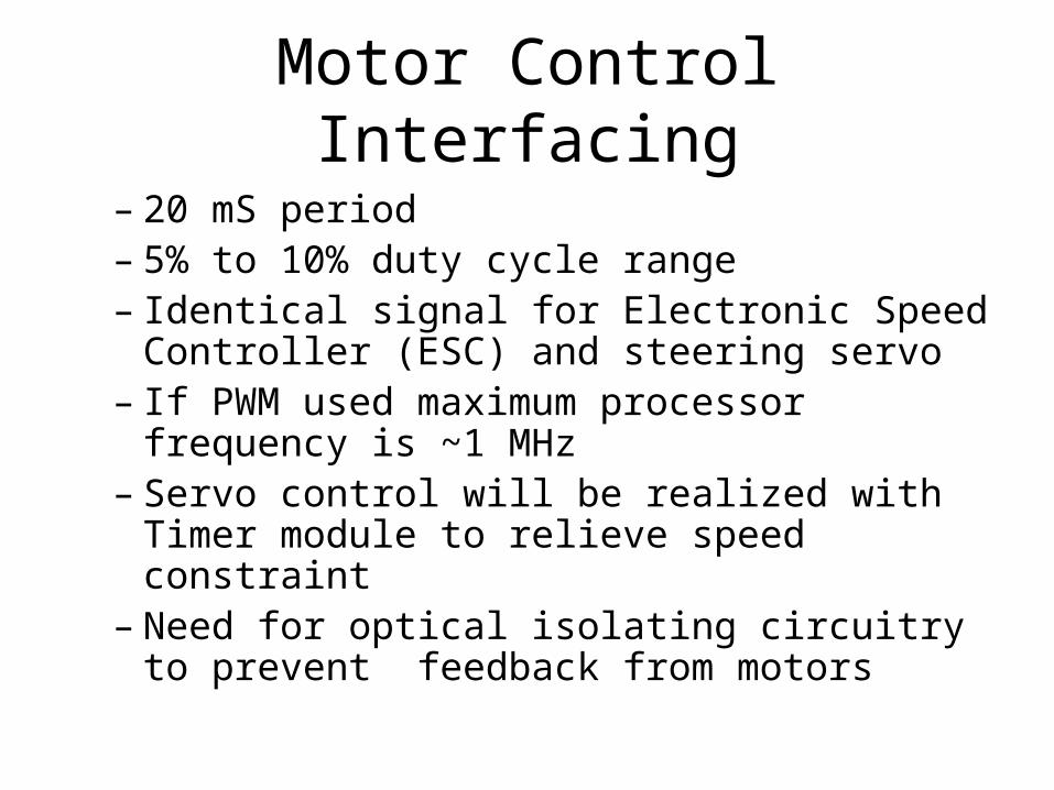
Motor Control Interfacing
– 20 mS period– 5% to 10% duty cycle range– Identical signal for Electronic Speed Controller
(ESC) and steering servo– If PWM used maximum processor frequency
is ~1 MHz – Servo control will be realized with Timer
module to relieve speed constraint– Need for optical isolating circuitry to prevent
feedback from motors

Current Draw
Manufacturer Part Vdd (V) Idd mA
Garmin GPS 18 5 Hz 4.0 - 5.5 60
Microchip PIC 18F2410 4.2 - 5.5 40
PING 2015 5 35
Hitachi HM55B 4.8-5.2 7
Crystalfontz CFAH0802A 4.75-5.25 1
Total 143
-Power options are limited to available RC batteries which range from 7.2 – 8.2 V 3300 mAh to 4400 mAh.

Block Diagram
uC
Ant.In
Vehicle Control Module:Controls the Driver Motor,
Wheel Alignment,Monitors (Query for):
Vehicle Speed, WheelAlignment Turning Direction
Route Navigation Module:Knows previous and next
waypointControls movementbetween waypoints
PWMPWM
Range Sensor:PING))) UltraSonic Sensor
detects object between 2cm and3m
Steering Servo
1 WireControl
Motor Controller
1 WireControl
Debug Header6 Lines
GPSAntenna
RS232
MUX
I/O
GPS EngineGarmin GPS 16 OEM
WAAS Capable
RS232
Digital Compass RS232
Hitachi HM55B
2
2 2
2


