Autodesk® Inventor® work flow for developing a top down manufacturing shop process Jim Dumont – Datamat Jeff Richlin – Richlin Machinery MA-2525 Autodesk Inventor can be used to save time, money, and scrap in manufacturing. Successfully manufacturing a product is not only about the final product, it also includes how you get there. Use Inventor to work backwards to develop all the process steps of manufacturing a part. Design the finished part you need, then with iParts and iLogic you can engineer all steps needed to get from a block of steel to a finished part. We will show a workflow that takes advantage of the associative abilities of the “I” tools. As your finished product evolves all of the production steps change as well. This work flow enables you to develop documentation for inspection, fabrication, etc, work holding, fixturing, and machining 3D models of each progression. Stress analysis of parts in process can be used to assure the process won’t damage the final product. We will also offer tips and tricks that help the manufacturing engineer incorporate Inventor on the shop floor. Learning Objectives After completing this class, attendees will be able to: Use iParts to describe process steps from start to finish. Incorporate tips and tricks relevant to Inventor and machining. Understand associative properties and parameters with regards to steps in a process. Build one typical model of a family, then automate the development steps for all variations. James Dumont - [email protected]James has more than 26 years experience with Autodesk products. He currently works as an Applications Engineer for an Autodesk® reseller, Datamat Programming Systems, located in Norwalk, CT. James has helped many companies become more efficient by understanding their needs and developing techniques and strategies to better use Inventor. He also presents at each Autodesk® Users Group that Datamat provides quarterly in three different states. James has been a guest speaker at Rhode Island's SME chapter as well as several local engineering colleges. Jeff Richlin - [email protected]Jeff is an Autodesk® Inventor® certified Professional user. His company that has provided custom built machinery and automated systems for 32 years. His clientele includes companies that produce products used in every facet of our lives: Medical, Commercial, Aerospace, and Automotive. Jeff has been a featured speaker at several Autodesk events including AU and World Press Day. He is an animated speaker who teaches as well as entertains. In addition to designing machinery, he is a guest lecturer at SUNY Farmingdale University for CAD and CNC machining, on the board of advisers for the Engineering and Manufacturing curriculum, co-chairs an Autodesk user’s group, and coaches a Robotics First team. Jeff is also an independent consultant offering training and engineering services.
Transcript
Autodesk® Inventor® work flow for developing a top down manufacturing shop process
Jim Dumont – Datamat Jeff Richlin – Richlin Machinery MA-2525
Autodesk Inventor can be used to save time, money, and scrap in manufacturing. Successfully manufacturing a product is not only about the final product, it also includes how you get there. Use Inventor to work backwards to develop all the process steps of manufacturing a part. Design the finished part you need, then with iParts and iLogic you can engineer all steps needed to get from a block of steel to a finished part. We will show a workflow that takes advantage of the associative abilities of the “I” tools. As your finished product evolves all of the production steps change as well. This work flow enables you to develop documentation for inspection, fabrication, etc, work holding, fixturing, and machining 3D models of each progression. Stress analysis of parts in process can be used to assure the process won’t damage the final product. We will also offer tips and tricks that help the manufacturing engineer incorporate Inventor on the shop floor.
LearningObjectives
After completing this class, attendees will be able to:
Use iParts to describe process steps from start to finish. Incorporate tips and tricks relevant to Inventor and machining. Understand associative properties and parameters with regards to steps in a process. Build one typical model of a family, then automate the development steps for all variations.
James Dumont - [email protected] James has more than 26 years experience with Autodesk products. He currently works as an Applications Engineer for an Autodesk® reseller, Datamat Programming Systems, located in Norwalk, CT. James has helped many companies become more efficient by understanding their needs and developing techniques and strategies to better use Inventor. He also presents at each Autodesk® Users Group that Datamat provides quarterly in three different states. James has been a guest speaker at Rhode Island's SME chapter as well as several local engineering colleges. Jeff Richlin - [email protected] Jeff is an Autodesk® Inventor® certified Professional user. His company that has provided custom built machinery and automated systems for 32 years. His clientele includes companies that produce products used in every facet of our lives: Medical, Commercial, Aerospace, and Automotive. Jeff has been a featured speaker at several Autodesk events including AU and World Press Day. He is an animated speaker who teaches as well as entertains. In addition to designing machinery, he is a guest lecturer at SUNY Farmingdale University for CAD and CNC machining, on the board of advisers for the Engineering and Manufacturing curriculum, co-chairs an Autodesk user’s group, and coaches a Robotics First team. Jeff is also an independent consultant offering training and engineering services.
Autodesk® Inventor® work flow for developing a top down manufacturing shop process
2
Introduction iParts can be used for more than just inserting members of a family on demand. This class will show how you can use iParts to create and then document a manufacturing process for a machined part from a blank casting. The first concern when designing a part is its functionality. The part’s features detail the part, not how you get there during manufacturing. In the manufacturing process there are steps that are required from the raw stock to the finished part. i.e.: Blank casting or block, roughing, finishing, drilling, tapping, polishing, and more. Each one of these steps needs to be represented as its own part. From these parts, detailed prints and process sheets are created. Interim parts can be created via different work flows.
Individual Parts created one at a time. This will take a lot of time. The results are not associative. And if changes are made, each part needs to be updated individually.
Derived Parts have similar issues to Individual Parts.
iLogic will create great results. However, it is more tool than is needed.
iParts can be used with awesome results. Start with the finished part from engineering. Then using iPart functions you create a member for each manufacturing step. Each step is associative to the previous one. If global changes are needed they are easy to implement using the family scope setting. By using the member scope setting, individual members can be modified for manufacturing processes. i.e.: adding material to be rough machined from the raw casting.
Before we get to the iParts workflow we will cover some basics of Inventor functional design tools. These tools are part of the new workflow:
Content Center (CC) – Quick review of CC along with tips about functions that you might have missed
o Creating your own R/W library o Creating a new category o Publishing content to your library
Bill of Material (BOM) – When working with parts, part families, parts lists, documentation and more, there are many times properties need to be modified. By using the BOM you can effect these changes quickly in a bidirectional way that saves a lot of time.
iParts – a quick review along with tips to make the process faster and easier.
Autodesk® Inventor® work flow for developing a top down manufacturing shop process
3
The process starts with the model of the finished part.
Finished Part The finish will be a set of prints for mfg steps Before we start on our part process let’s take a few side trips to learn about tools we will need. Inventor has a number of functional design tools to create and add parts to assemblies in place: Frame Generator, Bolted Connections, Power Transmission, Content Center and more.
Lets explore some of what Content Center (CC) has to offer The model created for the class is missing a set screw. Lets drop a screw from the CC. Open CC. Then, filter the search for set screws. Using filters will make finding parts in the CC much quicker.
Content Center – filtered Parts that you use over and over can be added to a “favorites” folder. This gives you quick access to them.
Autodesk® Inventor® work flow for developing a top down manufacturing shop process
4
Right Click and ADD TO FAVORITES Favorites shown.
The AUTO DROP needs to be enabled, “ON” is the default setting. Use the SELECT OTHER tool to allow selecting in an assembly to add contraints
Hover over the geometry for it to self pick the Click and drag for length selection. size. Click on the edge of the hole. It will size and constrain the component to the part. The dropped part is constrained on the hole diameter. Adding a tangent constraint between the pin and the screw fixes its location. Now that we have seen some of the functionality of the CC we will move on to iPart functions.
Autodesk® Inventor® work flow for developing a top down manufacturing shop process
5
This is a jaw tooth that we will be using, it has multiple configurations.
iPart Table with 2 primary keys defined.
An iMate is added to the part for easy placement in assemblies.
Autodesk® Inventor® work flow for developing a top down manufacturing shop process
6
See how an iPart works in an assembly. Place the part parent and choose the configuration. Use iMate to constrain – using ALT/drag method.
Next click on PATTERN COMPONENT.
By using the MEASURE tool you get the pattern distance from the hole spacing.
Autodesk® Inventor® work flow for developing a top down manufacturing shop process
7
Next publish the parts to the CC to create a more consistent work flow for company standard operations. Publishing into the CC requires a R/W library. The CC can be configured to access content from either the Vault Server or the Desktop Content.
The APPLICATION OPTIONS is accessed from the TOOLS menu on the ribbon.
The PROJECT PANEL showing the CONFIGURATION CC LIBRARY button.
Autodesk® Inventor® work flow for developing a top down manufacturing shop process
8
The library we will be using
Use the CC EDITOR to create a new category.
Set the LIBRARY VIEW to your R/W library if not defaulted already.
Create a top level category. This is different than creating a sub category. Right click in the CATEGORY VIEW AREA. Then enter the category name.
Autodesk® Inventor® work flow for developing a top down manufacturing shop process
9
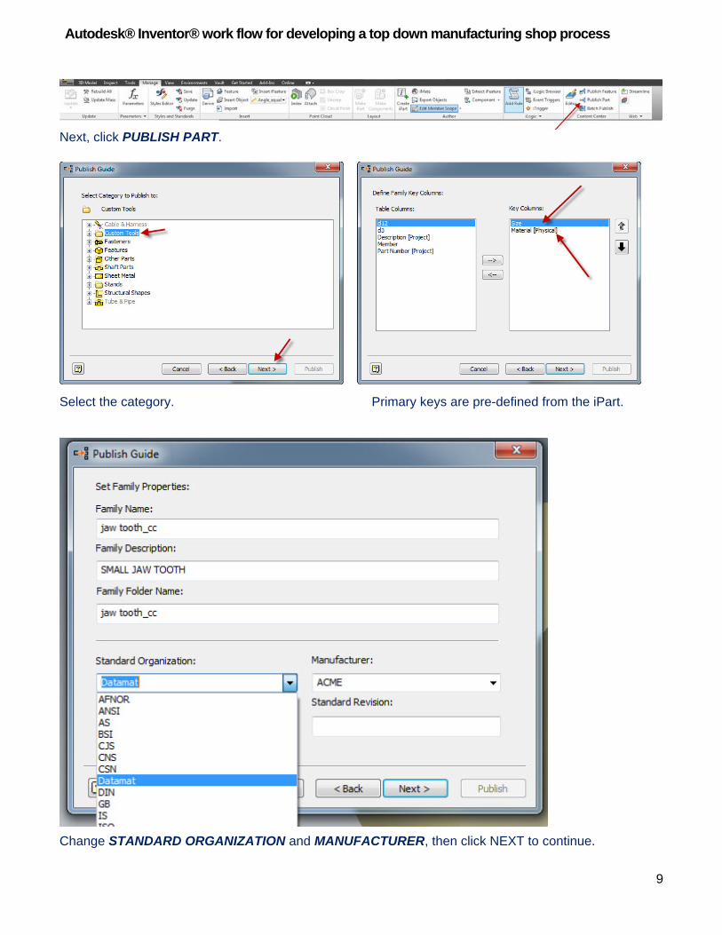
Next, click PUBLISH PART.
Select the category. Primary keys are pre-defined from the iPart.
Change STANDARD ORGANIZATION and MANUFACTURER, then click NEXT to continue.
Autodesk® Inventor® work flow for developing a top down manufacturing shop process
10
You can now place the new CC part as you would others. Select from the CUSTOM TOOLS folder. Choose the size and the material. Use the iMate to constrain the part.
Use COMPONENT PATTERN with the FEATURE PATTERN select option. Lets take a look at the benefits of using the CC for iParts. All CC standard or custom parts have the same behavior. For example, if you want to change the size of the set screw, right click CHANGE SIZE .
Autodesk® Inventor® work flow for developing a top down manufacturing shop process
11
If needed, change a part that has been included as a patterned part. To replace the tooth in our jaw use the SELECT PART PRIORITY instead of having to go find the part in the assembly browser. This is faster and simpler.
Right click and change size and then choose a new member. To change a standard part or iPart without the CC takes longer. We can still use the SELECT PART PRIORITY filter, but then we must find the part in the browser.
Find the part in the browser. Select (+) to expand, right click on the table, CHANGE COMPONENT A work flow with iParts published into the CC is consistent. Not using iParts in CC requires more work. Picking one work flow for all company users makes training more productive. Publishing your iParts will make your company more productive overall.
Autodesk® Inventor® work flow for developing a top down manufacturing shop process
12
iParts vs iLogic Why use iParts when you could use iLogic or even Derived Parts? First, let’s make clear why you would choose to use iParts over iLogic. iParts are used when there are limited numbers of members. With our tooth example we might have up to a dozen variations i.e.: Material, Diameter, or Length. So it is fitting to use iParts. iLogic is used when the number of members is unknown and you will be using rules to control other parts whether they are iParts or not. Consider a part that has hundreds of possible variations. Go with iLogic.
Autodesk® Inventor® work flow for developing a top down manufacturing shop process
13
Bill of Material A quick look at some of the advantages of working with the BOM. Changes to part and assembly properties can be managed better and faster from the BOM
Lets take a look at a possible drawing created from our ManGrip assembly. In this drawing the balloons are out of sequence. Also notice that most of the parts do not have descriptions.
Above is the opened parts list for the assembly on this sheet.. You can change the order and add descriptions here. DO NOT DO THIS! Go to the next page.
Autodesk® Inventor® work flow for developing a top down manufacturing shop process
14
If the changes are made in the drawing parts list they are static. Static is BAD. Well not really bad, just bad karma. Data changed in the parts list is only on the sheet being worked on. Changing in the BOM fixes both the part and drawing issues. Bidirectional changes are so much better than static ones.
Use the BOM to make your changes.
Remove the static values, then right click the parts list to go to the BOM.
BOM has three tabs: MODEL DATA, STRUCTURED and PARTS ONLY
Autodesk® Inventor® work flow for developing a top down manufacturing shop process
15
MODEL DATA – is a true representation of what makes up the assembly including reference components, phantom connections from bolted connections, ect, STRUCTURED TAB – representative of what will be displayed in the parts list, top level components and sub assemblies. PARTS ONLY TAB – breaks the structure down and displays only parts, even within subassemblies. By default PARTS ONLY is disabled.
Use right click on the PARTS ONLY tab to enable it. The STRUCTURE TAB shows first level components and sub assemblies. If you want to show sub assembly parts in the parts list and drawing, you must configure the STRUCTURE TAB to display all levels.
Right click to VIEW PROPERTIES Drop down and display ALL LEVELS. In STRUCTURE TAB you will see your parts. If they are grayed out, they are not checked out from vault. You can add descriptions in BOM (if the parts are checked out) and it will change component properties – ie description, part number, material. You can also reorder parts in BOM. This will change the order in the parts list. Grab and move the part up or down the list. If you do not see the column you want to change, then use the CHOOSE COLUMNS button:
Autodesk® Inventor® work flow for developing a top down manufacturing shop process
16
Click and drag MATERIAL to the header of the BOM to display. Change material here. It is much faster than opening each part individually. You can even copy and paste values.
Autodesk® Inventor® work flow for developing a top down manufacturing shop process
17
Once you have rearranged the parts into the order you want, use the RENUMBER ITEMS button.
The parts list is up to date, with no static values, Yippy!
Changes in the BOM bidirectionaliy automatically updates the parts list.
Note: Balloons also automatically update
Autodesk® Inventor® work flow for developing a top down manufacturing shop process
18
Continuing with the BOM, CC parts come over with predefined part numbers determined by Autodesk/industry standards, not yours. Create CC parts that adhere to your standards.
To change part numbers go to CONTENT CENTER EDITOR. Original cc content is grayed out - it cannot be changed. Copy a family to your R/W library to make changes.
Find the family you want to change, right click it, then use COPY TO.
Use LIBRARY VIEW to select your R/W library.
Autodesk® Inventor® work flow for developing a top down manufacturing shop process
19
Go to family table. Right click the FAMILY MEMBER to get to FAMILY TABLE.
Use the filter to reduce clutter and go to IPROPERTIES COLUMN ONLY.
Find the sizes you want to rename, and change the part number to meet company standards.
Autodesk® Inventor® work flow for developing a top down manufacturing shop process
20
The changes will not show immediately in BOM.
Synchronization needs to take place with previously used content and updates to the family tables. We do that with a REFRESH
Autodesk® Inventor® work flow for developing a top down manufacturing shop process
21
You should see the STANDARD COMPONENT REFRESH window showing the CC components that are out of sync with libraries. Click REFRESH.
Updated BOM. If the descriptions are also to be changed, a column needs to be added. Do this in the CONTENT CENTER EDITOR. FAMILY TABLE EDIT, Add a new column and map to DESCRIPTION IPROPERTY.
Use add column button.
Autodesk® Inventor® work flow for developing a top down manufacturing shop process
22
Set the column name, description, and an expression. Notice the expression is made from a prefix of HSSS- and then data from the size designation.
The completed form.
The new column with the new descriptions. Click REFRESH CONTENT CENTER to update changes from the libraries to the components.
The BOM showing new part number and description
Autodesk® Inventor® work flow for developing a top down manufacturing shop process
23
Use iParts to create part process steps and drawings Before we start, rename the features of the part so they will be easier to work with when they are suppressed to create steps in the processes.
Note: This part is not the used in this class. It is here to represent changes to the feature’s names.
We will start with the finished part, and turn it into an iPart.
Autodesk® Inventor® work flow for developing a top down manufacturing shop process
24
Click OK, then right click the only member to create a new row.
Change part numbers as shown.
Make the part number column a primary key.
Autodesk® Inventor® work flow for developing a top down manufacturing shop process
25
Set to MEMBER SCOPE. This is important since the changes to be made from now on are made to only the item being modified. Not all the members in the family. Changing individual members is a major part of this work flow.
Lets repeat: Using iParts allows us to change each member individually to create the
modifications needed for each process step. Next we will create the rough part (casting) member. It is the finished part with only the first extrusion unsuppressed plus material added to create the blank casting. This philosophy is what drives this work flow. Choosing the correct scope setting allows modifications to specific members or the entire family.
Select the Raw Stock member. Then suppress all the features except the first one. What will be left is the first extrusion without any of the finishing details. We need to add material to this to bring it to the size required to begin the rough machining operations.
Autodesk® Inventor® work flow for developing a top down manufacturing shop process
26
To add uniform material around the part we create a new parameter. This is so that if we want to change the roughing material, it can be done easily. In the parameters dialog box click ADD NUMERIC. Enter the name “ExcessStock”. Here we have given it a value of .1”
Make adjustments so that the part will be that much larger all around. Open the feature sketch. Edit the sketch dimensions. By adding and subtracting the parameter value, as needed, the part will grow.
Here you see the UpperWidth parameter with the original value plus the ExcessStock value.
Autodesk® Inventor® work flow for developing a top down manufacturing shop process
27
Sketch with changed dimensions.
Use the MOVE FACE command where we could not modify the sketch. Remember, we are not adding a new feature to the part, we are modifying an existing one!
Autodesk® Inventor® work flow for developing a top down manufacturing shop process
28
Edit the feature for the width by adding the excess stock to the extrusion * 2.
Add the next two members to the iParts family. First will be drilling for the Pin Hole and then reaming it to get to the finished size. There is one family member for each operation.
Autodesk® Inventor® work flow for developing a top down manufacturing shop process
29
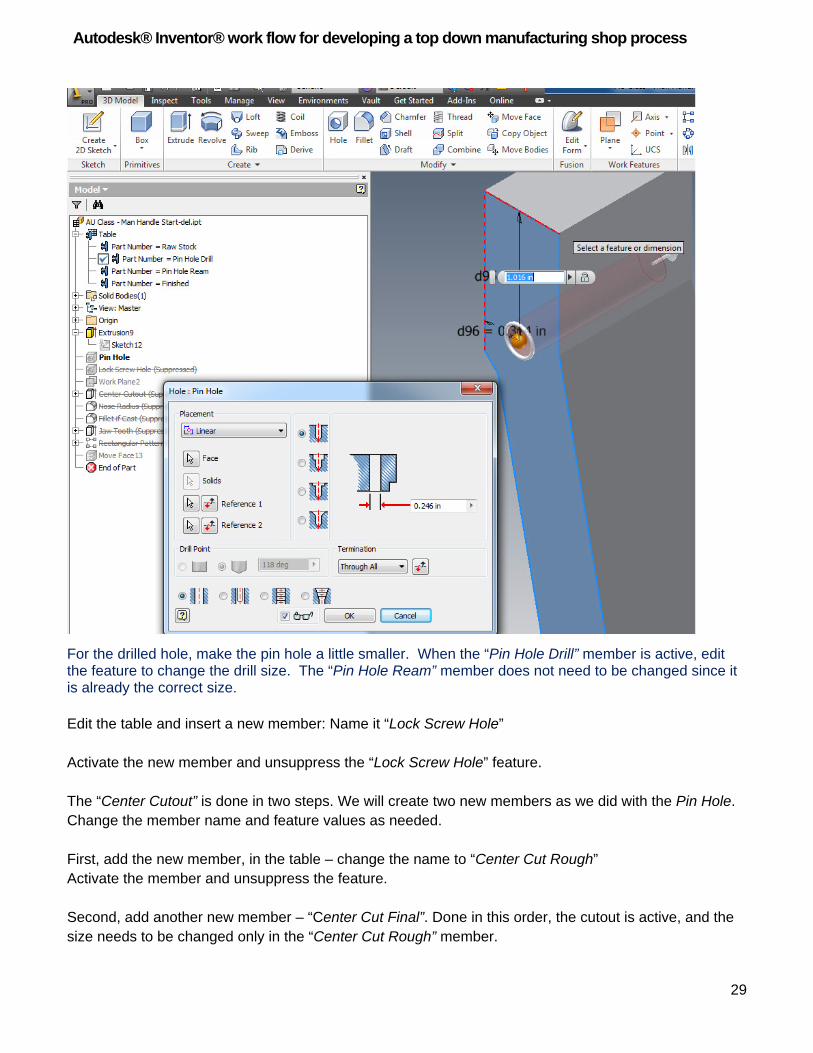
For the drilled hole, make the pin hole a little smaller. When the “Pin Hole Drill” member is active, edit the feature to change the drill size. The “Pin Hole Ream” member does not need to be changed since it is already the correct size. Edit the table and insert a new member: Name it “Lock Screw Hole” Activate the new member and unsuppress the “Lock Screw Hole” feature. The “Center Cutout” is done in two steps. We will create two new members as we did with the Pin Hole. Change the member name and feature values as needed. First, add the new member, in the table – change the name to “Center Cut Rough” Activate the member and unsuppress the feature. Second, add another new member – “Center Cut Final”. Done in this order, the cutout is active, and the size needs to be changed only in the “Center Cut Rough” member.
Autodesk® Inventor® work flow for developing a top down manufacturing shop process
30
Edit the Center Cut Rough sketch by reducing it .02” in both width and length.
The radius features are next. Make a new member for the radius operations. Then unsuppress the radius features in the new member.
Autodesk® Inventor® work flow for developing a top down manufacturing shop process
31
If no other operations are needed you are done. Remember we started with the finished part.
Be sure to generate all the member files from the parent. Everything is done from the parent. It does not matter how many members there are.
Autodesk® Inventor® work flow for developing a top down manufacturing shop process
32
Now to the documentation Create a new drawing
Drop the first part (raw stock) into your drawing, notice the member name in the browser. In the drawing we set the title block to show the model part number (this is dependent on your template file).
Create a new sheet, Drop the next member. Rename sheets accordingly (good area for an ap – next year’s class) Above you see a completed document with all sheets renamed.
Autodesk® Inventor® work flow for developing a top down manufacturing shop process
33
Why iParts vs Derived Parts
The advantage of iParts is you are working with a single file, the parent will control all of its members. Derived Parts need to be created and derived from each previous successive step to create the next process. Resulting in a lot of files to manage.
Creating a new family from the one we just made.
Lets make a change to the parent of our iPart jaw – change the width. Copy and rename the parent.
First set the member scope to “Edit Factory Scope” Open the Rough Stock member, Edit the feature for width from 1 to 1.5
The change propagates through the hole family. We do not have to open each and make changes.
Autodesk® Inventor® work flow for developing a top down manufacturing shop process