5 March 2022 Americas Bosch Security Systems, Inc. 130 Perinton Parkway Fairport, New York, 14450, USA Phone: + 1 800 289 0096 Fax: +1 585 223 9180 [email protected]h.com www.boschsecurity.us Europe, Middle East, Africa Bosch Security Systems B.V. P.O. Box 80002 5600 JB Eindhoven, The Netherlands Phone: + 31 40 2577 284 Fax: +31 40 2577 330 emea.securitysystems@bosch. com www.boschsecurity.com Asia-Pacific Robert Bosch (SEA) Pte Ltd, Security Systems 11 Bishan Street 21 Singapore 573943 Phone: +65 6571 2600 Fax: +65 6571 2698 apr.securitysystems@bosch .com www.boschsecurity.com Product Guide Specification SECTION 28 23 29 VIDEO SURVEILLANCE REMOTE DEVICES AND SENSORS BOSCH MIC IP starlight 7000i PART 1 – GENERAL 1.1 SUMMARY Specifier Notes: This product guide specification is written according to the Construction Specifications Institute (CSI) 3-Part Format, based on MasterFormat 2004 and The Project Resource Manual—CSI Manual of Practice. The Manufacturer is responsible for technical accuracy. The section must be carefully reviewed and edited by the Architect or Engineer to meet the requirements of the project and local building code. Words and sentences within brackets [ ] are choices to include or exclude
Transcript
7 May 2023
AmericasBosch Security Systems, Inc.130 Perinton ParkwayFairport, New York, 14450,USAPhone: + 1 800 289 0096Fax: +1 585 223 [email protected]
SECTION 28 23 29VIDEO SURVEILLANCE REMOTE DEVICES AND SENSORS
BOSCH MIC IP starlight 7000i
PART 1 – GENERAL
1.1 SUMMARY
A. Related Sections1. Section [28 23 13 – Video Surveillance Control and Management Systems].2. Section [28 23 16 – Video Surveillance Monitoring and Supervisory Interfaces].3. Section [28 23 19 – Digital Video Recorders and Analog Recording Devices].4. Section [28 23 23 – Video Surveillance Systems Infrastructure].
**********Specifier’s note: Include those standards referenced elsewhere in this SECTION.
Specifier Notes: This product guide specification is written according to the Construction Specifications Institute (CSI) 3-Part Format, based on MasterFormat 2004 and The Project Resource Manual—CSI Manual of Practice. The Manufacturer is responsible for technical accuracy.
The section must be carefully reviewed and edited by the Architect or Engineer to meet the requirements of the project and local building code. Words and sentences within brackets [ ] are choices to include or exclude a particular item or statement. Coordinate this section with other specification sections and the Drawings. Delete all “Specifier Notes” after editing this section.
A. Product Safety compliance1. Underwriters Laboratories standard UL 60950-1 Ed.2.2. Underwriters Laboratories standard UL 62368-1.3. AS/NZS CISPR 32 Radiated & Conducted Emissions (RMC)
B. International Electrotechnical Commission (IEC) compliance:1. IEC 60950-1, Ed.2. -- General safety requirements2. IEC 62368-1 – Safety3. IEC 60950-22 – Safety, equipment to be installed outdoors4. IEC 60068-2-1, edition 6.0 – Cold operational and Cold Endurance/Storage5. IEC 60068-2-2, edition 5.0 – Dry Heat operational and Dry Heat
Endurance/Storage6. IEC 60068-2-30 – Humidity7. IEC 60529, edition 2.2 – Ingress, meets IP68 when installed on MIC Deep
Conduit Adapter (DCA) or MIC Wall Mount accessories8. IEC 60529, edition 2.2 – Ingress, meets IP67 when not installed on MIC Deep
Conduit Adapter (DCA) or MIC Wall Mount accessories, but with MIC-IP67-5PK kit
C. European Norm compliance1. Complies with CE Product Safety regulations2. Complies with EN Product Safety standards3. Complies with Low Voltage Directive (LVD) 2014/35/EU4. EN 50581 – Complies with Restriction of Hazardous Substances (RoHS)
directive, Compliant to 2011/65/EU5. Complies with EMC directive 2014/30/EU6. EN 50121-4 -- Railway Applications, Electromagnetic Compatibility: Emission
and Immunity of the Signaling and Telecommunications Apparatus.7. EN 50130-4 -- Alarm Systems - Electromagnetic Compatibility8. EN 55032 – Radiated and Conducted Emissions9. EN 61000-3-2 – Mains Harmonic Current Emissions10. EN 61000-3-3 – Mains Voltage fluctuations and flicker11. EN 62368-1 – Audio/Video safety12. EN 61000-4-2 – ESD Susceptibility13. EN 61000-4-3 – Radiated electromagnetic fields14. EN 61000-4-4 – Electrical Fast Transient (EFT) Burst15. EN 61000-4-5 – Surge16. EN 61000-4-6 – Conducted Immunity17. EN 61000-4-11 – Voltage Dip and Short Interruption18. EN 60950-1 -- ITE Product Safety19. EN 60950-22 – Outdoor rating20. EN50132-7, scope A – DORI detection/observation/recondition/identification
distances for visible video images
Project Name/Project #/5-7-23 28 23 29 - 2 Video Surveillance Remote Device and Sensors
3
D. Canadian Standards Association (CSA) compliance1. CSA product safety standards CAN/CSA-C22.2 No.E60950-1B-07
E. Complies with Canada ICES-003 regulations.
F. Federal Communications Commission (FCC) Compliance1. Complies with FCC 47 CFR Part 15, Subpart B, Class A.
G. Mil-Std compliance1. Mil-Std-167-1A -- Sinusoidal Vibration2. Mil-Std-S-901D -- Hammer Shock, Medium weight3. Mil-Std-810-G, 510.5 – Sand and Dust4. Mil-Std-810-G, 506.5 – Rain5. Mil-Std-810-G, 505.5 – Solar Radiation6. Mil-Std-810-G, 501.5 – High Temperature7. Mil-Std-810-G, 502.5 – Low Temperature8. Mil-Std-810-G, 503.5 – Temperature Shock9. Mil-Std-810-G, 509.5 – Salt Fog10. Mil-Std-810-G, 521.3 – Ice/Freezing Rain
H. Other Environmental compliance ratings1. UL standard UL50E – Ingress, Type 6P2. Cold Start: Able to start-up from -45C after 2 hours of warm-up3. Corrosion resistance
5. ASTM D 3359 -- Paint Adhesion, method B, Cross-hatch6. Audible Noise – Meets <65dB average noise during pan/tilt operations
I. HD standards1. Complies with the SMPTE 274M-2008 Standard in:
a.Resolution: 1920x1080 b.Scan: Progressivec.Color representation: complies with ITU-R BT.709d.Aspect ratio: 16:9e.Frame rate: 25, 30, 50 and 60 frames/s
2. Complies with the 296M-2001 Standard in:a.Resolution: 1280x720 b.Scan: Progressivec.Color representation: complies with ITU-R BT.709d.Aspect ratio: 16:9e.Frame rate: 25, 30, 50 and 60 frames/s
J. International Organization for Standardization (ISO)1. ISO 9001 – Quality System.
K. Other
Project Name/Project #/5-7-23 28 23 29 - 3 Video Surveillance Remote Device and Sensors
4
1. 24VAC power source – Able to be powered using nominal 24VAC power source
2. High PoE power source – Able to be powered using 95W High PoE power source when connected to network cable (CAT5/6) having <=100m length
3. Redundant power source – Able to be powered using both 24VAC and High PoE providing a redundant power source operating mode
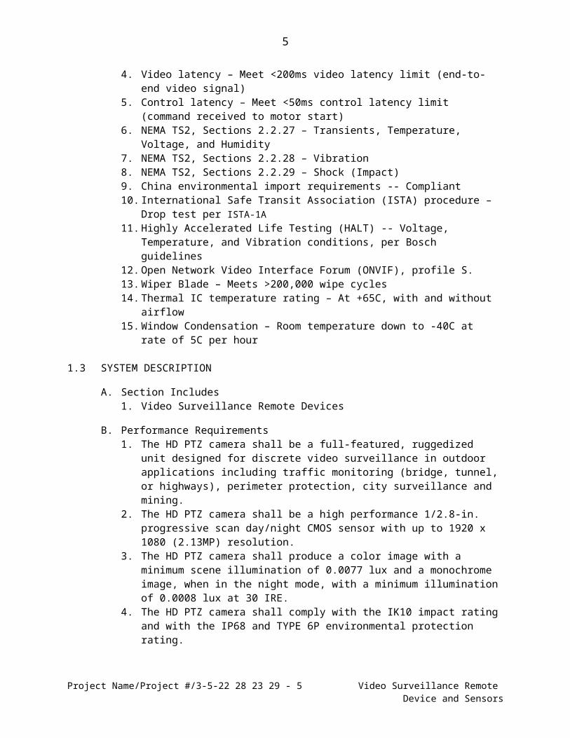
4. Video latency – Meet <200ms video latency limit (end-to-end video signal)5. Control latency – Meet <50ms control latency limit (command received to motor
start)6. NEMA TS2, Sections 2.2.27 – Transients, Temperature, Voltage, and Humidity7. NEMA TS2, Sections 2.2.28 – Vibration8. NEMA TS2, Sections 2.2.29 – Shock (Impact)9. China environmental import requirements -- Compliant10. International Safe Transit Association (ISTA) procedure – Drop test per ISTA-1A11. Highly Accelerated Life Testing (HALT) -- Voltage, Temperature, and Vibration
conditions, per Bosch guidelines12. Open Network Video Interface Forum (ONVIF), profile S.13. Wiper Blade – Meets >200,000 wipe cycles14. Thermal IC temperature rating – At +65C, with and without airflow15. Window Condensation – Room temperature down to -40C at rate of 5C per
hour
1.3 SYSTEM DESCRIPTION
A. Section Includes1. Video Surveillance Remote Devices
B. Performance Requirements1. The HD PTZ camera shall be a full-featured, ruggedized unit designed for
discrete video surveillance in outdoor applications including traffic monitoring (bridge, tunnel, or highways), perimeter protection, city surveillance and mining.
2. The HD PTZ camera shall be a high performance 1/2.8-in. progressive scan day/night CMOS sensor with up to 1920 x 1080 (2.13MP) resolution.
3. The HD PTZ camera shall produce a color image with a minimum scene illumination of 0.0077 lux and a monochrome image, when in the night mode, with a minimum illumination of 0.0008 lux at 30 IRE.
4. The HD PTZ camera shall comply with the IK10 impact rating and with the IP68 and TYPE 6P environmental protection rating.
5. The HD PTZ camera shall comply with the ASTM B117 salt spray standard.6. The HD PTZ camera shall be engineered to withstand high-impact or
continuous low-frequency vibration.7. The HD PTZ camera shall support the following dual, redundant power options:
a. Without illuminator: 1) 24 VAC or Bosch VIDEOJET connect (VJC-7000-90)2) Bosch 60 W Midspan (NPD-6001A)
b. With illuminator: 1) 24 VAC or Bosch VIDEOJET connect (VJC-7000-90)2) Bosch 95 W Midspan (NPD-9501A)3) The HD PTZ camera shall default to use power from the Midspan
power supply, if connected.
Project Name/Project #/5-7-23 28 23 29 - 4 Video Surveillance Remote Device and Sensors
5
4) The HD PTZ camera shall switch to the 24 VAC power supply if power from Midspan is lost, with no interruption to camera operation.
8. The HD PTZ camera shall provide Intelligent Tracking to continuously track objects in motion.
9. The HD PTZ camera shall offer High Dynamic Range (120 dB) for images with simultaneous bright and dark areas.
10. The HD PTZ camera shall provide direct network connection using H.264, H.265 and JPEG compression and bandwidth throttling to efficiently manage bandwidth and storage requirements while delivering outstanding image quality.
11. The HD PTZ camera shall offer embedded Intelligent Video Analysis (IVA) that eliminates dedicated PCs and associated software maintenance.
12. The HD PTZ camera shall conform to the ONVIF standard to provide interoperability with other conformant systems.
13. The HD PTZ camera shall offer configurable quad streaming with individually configurable HD streams.
14. The HD PTZ camera shall have an autofocus lens with 360x zoom (30x optical/12x digital).
15. The HD PTZ camera shall have variable pan and tilt speeds, and autopivot capability for optimal camera control and viewing at all zoom levels.
16. The HD PTZ camera shall offer a defog image feature that assists the camera in registering a usable image when viewing foggy or other low-contract scenes.
17. The HD PTZ camera shall be compatible with an optional, field-installable MIC illuminator.
18. The HD PTZ camera shall be able to compatible with an optional, field-installable MIC illuminator.
19. The HD PTZ camera shall be able to control optional illuminator to produce white light to capture full scene details in color.
20. The HD PTZ camera shall be able to control optional illuminator produce covert 940m IR array to make invisible illumination.
21. The HD PTZ camera shall be able to produce 850m IR array to allow detection of objects at a maximum distance of 450m.
22. The HD PTZ camera shall be capable of operating in an outdoor environment within the following temperature range: -40°C to +65°C (-40°F to 149°F)
Project Name/Project #/5-7-23 28 23 29 - 5 Video Surveillance Remote Device and Sensors
6
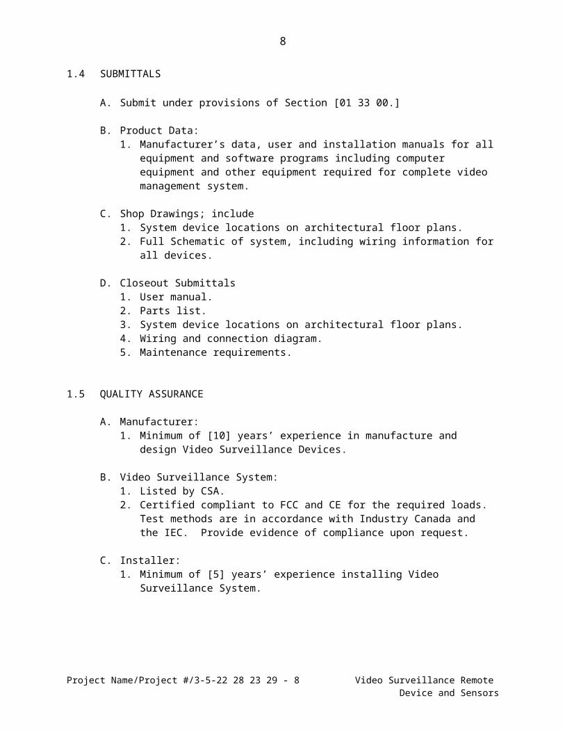
1.4 SUBMITTALS
A. Submit under provisions of Section [01 33 00.]
B. Product Data:1. Manufacturer’s data, user and installation manuals for all equipment and
software programs including computer equipment and other equipment required for complete video management system.
C. Shop Drawings; include1. System device locations on architectural floor plans.2. Full Schematic of system, including wiring information for all devices.
D. Closeout Submittals1. User manual.2. Parts list.3. System device locations on architectural floor plans.4. Wiring and connection diagram.5. Maintenance requirements.
1.5 QUALITY ASSURANCE
A. Manufacturer:1. Minimum of [10] years’ experience in manufacture and design Video
Surveillance Devices.
B. Video Surveillance System:1. Listed by CSA.2. Certified compliant to FCC and CE for the required loads. Test methods are in
accordance with Industry Canada and the IEC. Provide evidence of compliance upon request.
C. Installer:1. Minimum of [5] years’ experience installing Video Surveillance System.
Project Name/Project #/5-7-23 28 23 29 - 6 Video Surveillance Remote Device and Sensors
7
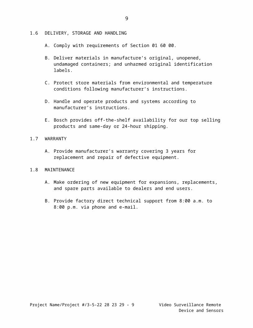
1.6 DELIVERY, STORAGE AND HANDLING
A. Comply with requirements of Section 01 60 00.
B. Deliver materials in manufacture’s original, unopened, undamaged containers; and unharmed original identification labels.
C. Protect store materials from environmental and temperature conditions following manufacturer’s instructions.
D. Handle and operate products and systems according to manufacturer’s instructions.
E. Bosch provides off-the-shelf availability for our top selling products and same-day or 24-hour shipping.
1.7 WARRANTY
A. Provide manufacturer’s warranty covering 3 years for replacement and repair of defective equipment.
1.8 MAINTENANCE
A. Make ordering of new equipment for expansions, replacements, and spare parts available to dealers and end users.
B. Provide factory direct technical support from 8:00 a.m. to 8:00 p.m. via phone and e-mail.
Project Name/Project #/5-7-23 28 23 29 - 7 Video Surveillance Remote Device and Sensors
8
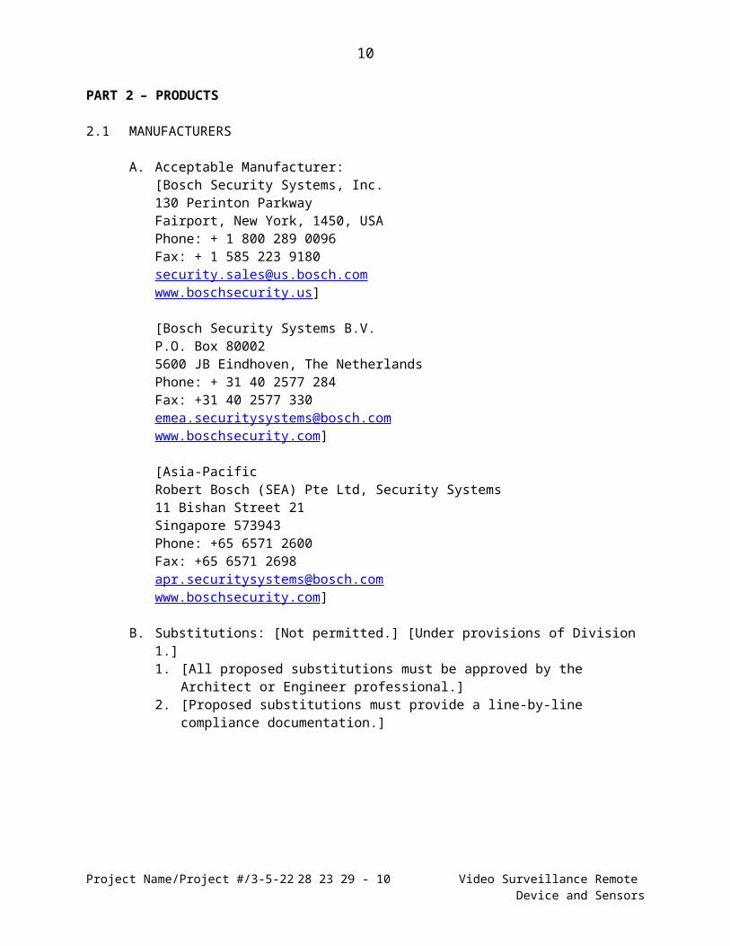
PART 2 – PRODUCTS
2.1 MANUFACTURERS
A. Acceptable Manufacturer:[Bosch Security Systems, Inc.130 Perinton ParkwayFairport, New York, 1450, USAPhone: + 1 800 289 0096Fax: + 1 585 223 [email protected]]
[Bosch Security Systems B.V.P.O. Box 800025600 JB Eindhoven, The NetherlandsPhone: + 31 40 2577 284Fax: +31 40 2577 [email protected]]
B. Substitutions: [Not permitted.] [Under provisions of Division 1.]1. [All proposed substitutions must be approved by the Architect or Engineer
professional.]2. [Proposed substitutions must provide a line-by-line compliance documentation.]
2.2 BOSCH MIC IP starlight 7000i [MIC-7502-Z30B] [MIC-7520-Z30W] [MIC-7520-Z30G] A. General Characteristics:
1. The HD PTZ camera shall offer Intelligent Tracking that controls the pan, tilt, and zoom movements of the camera to continuously follow an object or individual.
2. The HD PTZ camera shall be able to detect moving objects when camera is on guard tour or when PTZ function is controlled manually.
3. The HD PTZ camera shall be engineered to withstand high-impact or continuous low-frequency vibration. The HD PTZ camera shall be compatible with a full set of accessories that support upright/inverted/canted mounting configurations on flat surfaces, walls, ceilings, poles, and building corners.
Project Name/Project #/5-7-23 28 23 29 - 8 Video Surveillance Remote Device and Sensors
B. Imaging1. The HD PTZ camera shall offer a 1/2.8-inch type CMOS imager.2. The HD PTZ camera shall offer an effective number of pixels of 1945 x 1097
(2.13 megapixels).3. The HD PTZ camera shall offer a 16:9 aspect ratio.4. The HD PTZ camera shall offer a 30x optical zoom lens (4.3 to 129 mm).5. The HD PTZ camera shall offer a 12x digital zoom.6. The HD PTZ camera shall have 2.3° to 65° field of view.7. The HD PTZ camera shall produce a color image with a minimum scene
illumination of 0.0077 lux and a monochrome image, when in the night mode, with a minimum illumination of 0.0008 lux at 30 IRE.
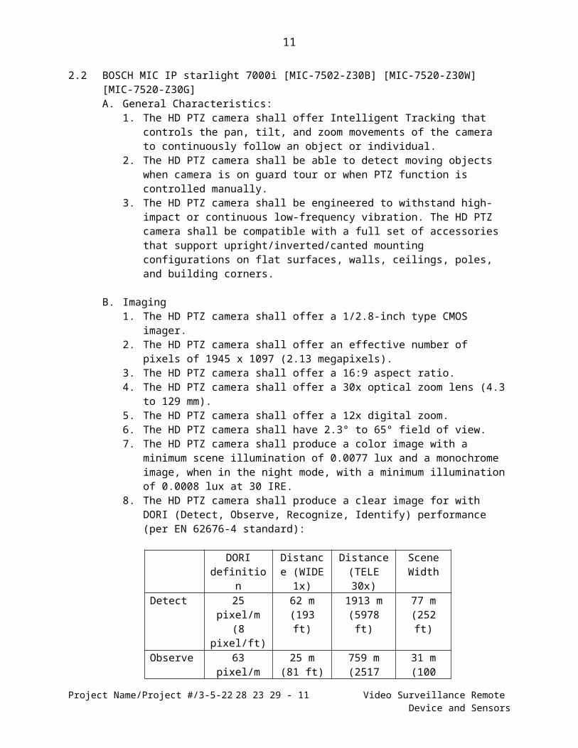
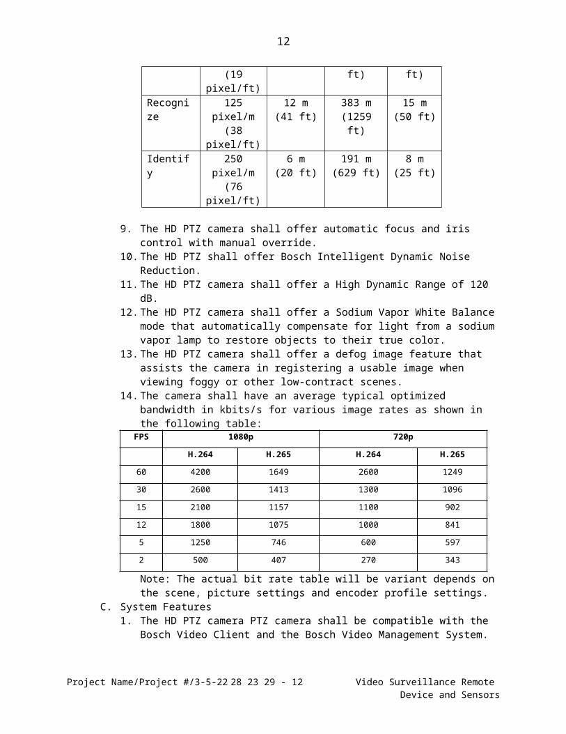
8. The HD PTZ camera shall produce a clear image for with DORI (Detect, Observe, Recognize, Identify) performance (per EN 62676-4 standard):
DORI definition
Distance (WIDE 1x)
Distance(TELE 30x)
Scene Width
Detect 25 pixel/m(8 pixel/ft)
62 m(193 ft)
1913 m(5978 ft)
77 m(252 ft)
Observe 63 pixel/m(19 pixel/ft)
25 m(81 ft)
759 m(2517 ft)
31 m(100 ft)
Recognize
125 pixel/m(38 pixel/ft)
12 m(41 ft)
383 m(1259 ft)
15 m(50 ft)
Identify 250 pixel/m(76 pixel/ft)
6 m(20 ft)
191 m(629 ft)
8 m(25 ft)
9. The HD PTZ camera shall offer automatic focus and iris control with manual override.
10. The HD PTZ shall offer Bosch Intelligent Dynamic Noise Reduction.11. The HD PTZ camera shall offer a High Dynamic Range of 120 dB.12. The HD PTZ camera shall offer a Sodium Vapor White Balance mode that
automatically compensate for light from a sodium vapor lamp to restore objects to their true color.
13. The HD PTZ camera shall offer a defog image feature that assists the camera in registering a usable image when viewing foggy or other low-contract scenes.
14. The camera shall have an average typical optimized bandwidth in kbits/s for various image rates as shown in the following table:
Note: The actual bit rate table will be variant depends on the scene, picture settings and encoder profile settings.
C. System Features
Project Name/Project #/5-7-23 28 23 29 - 9 Video Surveillance Remote Device and Sensors
10
1. The HD PTZ camera PTZ camera shall be compatible with the Bosch Video Client and the Bosch Video Management System.
2. The HD PTZ camera shall have several built-in sensors and offer advanced diagnostics that display warnings on the cameras on-screen display, including high and low temperature, low voltage, high humidity, high vibration, total hours of operation for camera and for illuminator.
D. PTZ Features1. The HD PTZ camera shall provide a brushless, integral pan/tilt motor drive unit.2. The HD PTZ camera shall provide a pan range of 360° continuous.3. The HD PTZ camera shall provide a tilt angle of
a.290° (upright orientation and auto pivot).b.250° (inverted orientation and auto pivot).186.6° with illuminators.
4. The HD PTZ camera shall offer the following tilt angles:a.Upright unit: -55° to +90°b.Canted unit: -90° to +90°c.Canted unit (with illuminator): -90° to +64°d.Inverted unit: -95° to +35°
5. The HD PTZ camera shall provide pan and tilt preset repeatability accurate to within +/-0.06° without illuminator (+/-0.07° with illuminator).
6. The HD PTZ camera shall offer variable pan speeds of 0.2°/second to 120°/second.
7. The HD PTZ camera shall offer a variable tilt speed of 0.2°/second to 90°/second.
8. The HD PTZ camera shall offer a pre-position speed of 120°/second.9. The HD PTZ camera shall divide the cameras 360º rotation into 16 independent
sectors with 20-character titles per sector. Any or all of the 16 sectors can be blanked from the operator's view.
10. The HD PTZ camera shall offer the ability to define 24 masks with up to 8 masks per scene that prohibit areas of the field of view from being seen even if the camera is panned, tilted, or zoomed.
11. The HD PTZ camera shall offer 24 virtual masks.12. The HD PTZ camera shall store up to 256 preset scenes with each preset
programmable for 20 character titles. 13. The HD PTZ camera shall support the following tour modes:
a.Recorded tours - two (2), maximum total duration 30 minutes (depending on amount of commands sent during recording).
b.Preset tour - one (1), consisting of up to 256 scenes consecutively, and (1) customized up to 64 scenes.
Project Name/Project #/5-7-23 28 23 29 - 10 Video Surveillance Remote Device and Sensors
11
E. Pre-programmed Modes1. The HD PTZ camera shall offer six pre-programmed but configurable user
modes.2. The pre-programmed modes shall be optimized with the best settings for the
following environments:a.General (default mode)b.Motionc.Low Lightd.Indoore.Vibrantf. Illuminator (only for MIC cameras with installed illuminators)
3. The HD PTZ camera shall allow users to customize these modes for the specific requirements of the camera site.
F. HD Characteristics1. [The HD PTZ camera shall generate full HD 1080p50/60 resolution and
720p50/60 resolution using H.264 compression (ISO/IEC 14496-10).]2. [The HD PTZ camera shall generate full HD 1080p50/60 resolution and
720p50/60 resolution using H.265 compression.]The HD PTZ camera shall generate multiple simultaneous configurable HD video streams.
3. The HD PTZ camera shall allow simultaneous streaming of individual HD streams, and allow a choice of HD resolution in combination with SD resolutions.
G. IP Connectivity1. The HD PTZ camera shall allow full camera control and configuration
capabilities via a TCP/IP network.2. The HD PTZ camera shall be capable of capturing and storing images using at
HD 1080p and HD 720p resolutions.3. The HD PTZ camera shall deliver 1080p video, at rates up to 60 images per
second via TCP/IP over Cat5/Cat6 UTP cable.4. The HD PTZ camera shall support operation with Internet Explorer web browser
version 7.0 or later, Bosch Configuration Manager, Bosch Video Management System (BVMS), Bosch Video Client (BVC), or other third party software.
5. The HD PTZ camera shall conform to the ONVIF standard.6. The HD PTZ camera shall conform to the SNMP v1 standard.7. The HD PTZ camera shall offer Quality of Service (QoS) configuration options.8. The HD PTZ camera shall support the IPv6 internet-layer protocol for packet
switched internetworking across multiple IP networks.9. The HD PTZ camera shall offer embedded Intelligent Video Analysis (IVA) that
eliminates dedicated PCs and associated software maintenance.
H. Intelligent Video Analysis1. The HD PTZ camera shall be capable of processing and analyzing video within
the camera itself, with no extra hardware required.2. The HD PTZ camera shall be capable of detecting and sending alarms for
abnormal events.3. The HD PTZ camera shall be configurable to analyze up to 10 different scenes
for one or more of the following events: Line Crossing, Loitering, Idle Object, Removed Object, Conditional Change, Trajectory Tracking, and Filters.
Project Name/Project #/5-7-23 28 23 29 - 11 Video Surveillance Remote Device and Sensors
12
4. The HD PTZ camera shall allow users to set up to 10 separate profiles and switch profiles based on a day/night or holiday schedules.
5. The HD PTZ camera shall support scene tours that automatically reposition the camera to each scene for a specified duration.
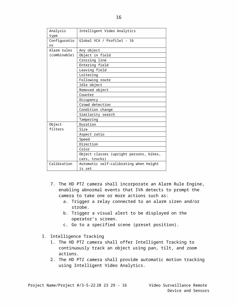
6. The HD PTZ camera shall feature the following Intelligent Video Analysis configurations, alarm rules, and object filters:
7. The HD PTZ camera shall incorporate an Alarm Rule Engine, enabling abnormal events that IVA detects to prompt the camera to take one or more actions such as:
a.Trigger a relay connected to an alarm siren and/or strobe.b.Trigger a visual alert to be displayed on the operator’s screen.c.Go to a specified scene (preset position).
I. Intelligence Tracking1. The HD PTZ camera shall offer Intelligent Tracking to continuously track an
object using pan, tilt, and zoom actions.2. The HD PTZ camera shall provide automatic motion tracking using Intelligent
Video Analytics.3. The HD PTZ camera shall have the ability to follow an object continually when
passing behind a privacy mask. 4. The HD PTZ camera shall allow a user to define virtual masks for a scene so
certain objects are not considered for flow analysis and will not trigger Intelligent Tracking.
Project Name/Project #/5-7-23 28 23 29 - 12 Video Surveillance Remote Device and Sensors
Analysis type Intelligent Video AnalyticsConfigurations Global VCA / Profile1 - 16Alarm rules (combinable)
Any objectObject in fieldCrossing lineEntering fieldLeaving fieldLoiteringFollowing routeIdle objectRemoved objectCounterOccupancyCrowd detectionCondition changeSimilarity searchTampering
Calibration Automatic self-calibrating when height is set
13
5. The HD PTZ camera shall offer the following control options for the Intelligent Tracking feature:
a.Off – the HD PTZ camera does not track moving object.b.Auto – the HD PTZ camera actively analyzes the video to detect moving
objects.c.Click – the HD PTZ camera allows a user to click a moving object in the
live video image to activate Intelligent Tracking.d.IVA-triggered – the HD PTZ camera continuously analyzes the scene for
IVA alarms or an IVA rule violation. If an alarm or rule violation is detected, the camera activates Intelligent Tracking to track the object that triggered the alarm or rule violation.
6. The HD PTZ camera shall have the ability to restart tracking if a target starts moving in the same area where the initial target stopped moving or if the camera detects an object moving along the last known trajectory.
7. The HD PTZ camera shall allow an operator to select an object to track in the live image view.
8. The HD PTZ camera shall automatically start tracking a target that violates an IVA rule or triggers an IVA alarm.
J. Access Security1. The HD PTZ camera shall offer three levels of password protection.2. The HD PTZ camera shall support 802.1x authentication using a RADIUS
(Remote Authentication Dial In User Service) server.3. The HD PTZ camera shall store a SSL certificate for use with HTTPS.4. The HD PTZ camera shall be capable of being independently AES encrypted
with 128-bit keys.
K. Installation Requirements1. The HD PTZ camera shall be capable of operating in an outdoor environment
within the following temperature range: -40 °C to +65 °C (-40 °F to +149 °F)2. The HD PTZ camera shall offer a cold start-up temperature of: -40 °C (-40 °F)
(Requires 60-minute warm-up prior to PTZ operations.)3. The HD PTZ camera shall accept power, transmit video, and accept control via
TCP/IP connection.4. The HD PTZ camera shall support the following dual, redundant power options:
a.Without illuminator: 1) 24 VAC or Bosch VIDEOJET connect (VJC-7000-90)2) Bosch 60 W Midspan (NPD-6001A)
b.With illuminator: 1) 24 VAC or Bosch VIDEOJET connect (VJC-7000-90)2) Bosch 95 W Midspan (NPD-9501A)
c.The HD PTZ camera shall switch to the High PoE or PoE+ power supply if power from the 24 VAC power supply is lost, with no interruption to camera operation.
5. The HD PTZ camera shall be able to be mounted in an upright, inverted, or canted position.
6. The HD PTZ camera shall be capable of being mounted to a wall, the corner of a wall, and to a pole using optional mounting hardware.
7. The HD PTZ camera shall offer an optional sunshield.
Project Name/Project #/5-7-23 28 23 29 - 13 Video Surveillance Remote Device and Sensors
14
8. The HD PTZ camera shall offer an optional external alarm/washer interface to connect external alarm signals and to control an optional external washer pump device.
9. The HD PTZ camera shall provide an optional IP67-rated weatherproofing kit for the camera’s electrical interface pigtail.The HD PTZ camera shall provide an optional hinged deep conduit adapter to facilitate connecting cables to the camera before the final bolts are installed.
10. The HD PTZ camera shall provide a multi-language on-screen display.
L. Housing Options 1. The HD PTZ camera shall be made of cast solid aluminum with a tempered flat
glass viewing window.2. The HD PTZ camera shall provide built-in surge protection for power, data, and
network inputs.3. The HD PTZ camera shall conform to the IP68 standard for a weather-resistant
package.4. The HD PTZ camera shall conform to the IP67 standard for a weather resistant
package when using the IP67 connector kit.5. The HD PTZ camera shall conform to the Type 6P standard for ingress
protection (when using installed MIC-DCA or MIC-WMB).6. The HD PTZ camera shall provide an integrated silicone wiper.7. The HD PTZ camera shall conform to the IK10 rating for external mechanical
impact.8. The HD PTZ camera shall conform to the following wind loads:
a.241 km/h (150 mph) (sustained) (Gusts up to 290 km/h (180 mph))b. Effective Projected Area (EPA): 0.070 m² (0.76 ft²)
9. The HD PTZ camera shall conform to the IEC 60068-2-6, Test Fc: Vibration (sinusoidal), 10m/s² (1.0g) and the Sinusoidal vibration test IAW MILSTD-167-1A vibration tests.
10. The HD PTZ camera shall conform to the IEC 60068-2-7, 40g, 6ms Half Sine Impulse; Medium weight Hammer Shock IAW MILS-901D test.
11. The HD PTZ camera shall be available in the following colors:a.Black (RAL 9005)b.White (RAL 9010)c.Grey (RAL 7001) (Specific regions only.)
12. The HD PTZ camera shall provide a corrosion protection surface treatment with powder coat paint, sand finish.
Project Name/Project #/5-7-23 28 23 29 - 14 Video Surveillance Remote Device and Sensors
15
M. Illumination1. The HD PTZ camera shall offer an optional, field-installable illuminator.2. The field-installable illuminator shall enable detection of objects at a maximum
distance of 450 m (1476 ft) with infrared (850 nm).3. The field-installable illuminator shall enable detection of objects at a maximum
distance of 250 m (820 ft) with White light.4. The field-installable illuminator shall offer Constant Light technology to
automatically control and adjust output to deliver a consistent level of illumination.
5. The field-installable illuminator shall offer both IR (940 nm and 850 nm) and White Light LEDs and shall allow operators to switch between the three sources.
6. The field-installable illuminator shall offer IR arrays with multiple beam angles (ranging from 16° to 47°) to provide illumination of a wide area of view.
7. The MIC camera shall steer the IR beam dynamically to match the illumination intensity with the camera’s field of view according to the zoom level.
8. The field-installable illuminator shall be a ruggedized unit designed for discrete video surveillance in outdoor applications including perimeter protection, city surveillance and mining.
N. Camera1. Imager: 1/2.8-inch type CMOS sensor2. Effective Picture Elements (Pixels): 1945 x 1097 (2.13 MP)3. Lens:
a.30x optical zoom, 4.3 to 129 mmb. F1.6 to F4.7c.12x digital zoomd.Field of View: 2.3° to 65°
4. Focus: Automatic with manual override5. Iris: Automatic with manual override 6. Gain Control: Auto/Manual7. Aperture Correction: Horizontal and vertical8. Electronic Shutter Speed (AES): 1/1 sec to 1/0000 sec (22 steps)9. High Dynamic Range of 120 dB10. Signal-to-Noise Ratio (SNR): >55 dB11. Backlight Compensation: On/Off12. White Balance: 2000 K to 10,000 K; ATW, AWB Hold, Extended ATW, Manual,
Sodium Lamp Auto, Sodium Lamp13. Day/Night: Monochrome, Color, Auto14. Defog Image Feature: Allows the camera to “see” and register a usable image
when viewing foggy or other low-contract scenes.
O. Mechanical1. Drive Unit: Brushless, integral pan/tilt motor drive2. Pan Range: 360° continuous rotation3. Tilt Angle:
Project Name/Project #/5-7-23 28 23 29 - 15 Video Surveillance Remote Device and Sensors
16
b.[Canted unit: −90° to +90°]5. Variable Pan Speed: 0.2°/second to 120°/second6. Variable Tilt Speed: 0.2°/second to 90°/second7. Intelligent Tracking Speed: >0.2°/second (minimum)8. Pre-position Speed: 120°/second9. Preset Accuracy::+/-0.06° (without illuminator); +/-0.07° with illuminator10. Proportional Pan/Tilt to Zoom: Yes11. Zoom Movement Speed:
a.<5 seconds (optical Wide to optical TELE)b.<7.5 seconds (optical Wide to digital TELE)
12. Audible Noise: <65 dB
P. Electrical1. Input Voltage: 21-30 VAC, 50/60 Hz and/or High Power over Ethernet (56 VDC
nominal)2. Power Consumption:
a. Without illuminator: 40 W maximumb. With illuminator: 70 W maximum
3. Current Consumption:a. 40 W (24 VAC): 2.4Ab. 70 W (24 VAC): 4.1Ac. 40 W (High PoE): 0.9Ad. 70 W (High PoE): 1.25A
Q. Software Control1. Via Internet Explorer web browser version 7.0 or later, Bosch Configuration
Manager, Bosch Video Management System (BVMS), Bosch Video Client (BVC), or support for third party software
2. Serial protocols: Bosch OSRD, Pelco P/D, Forward Vision, and Cohu (Note: For Pelco, Forward Vision, and Cohu protocols, a separate license (MVS-FCOMPRCL) is required.)
3. Software Update: Network firmware upload
R. Network1. Communications Protocols: Standard Bosch IP protocol, including ONVIF and
SNMP v12. Video Compression: H.265, H.264 (ISO/IEC 14496-10), M-JPEG, JPEG3. Streaming: Four (4) individually configurable streams: Two (2) independently
configurable recording streams plus two (2) additional non- recording streams. Configurable frame rate and resolution.
b. Options with “720P (1MP)” selected for Stream 1:1) 720P (1MP)2) D1 4:3 (cropped)3) 640x4804) 432 SD5) 288 SD6) 144 SD
8. Two (2) non-recording (I-frame only) streams/profiles: a. HD Image Optimized;b. HD Balanced;c. HD Bit Rate Optimized;d. SD Image Optimized;e. SD Balanced;f. SD Bit Rate Optimizedg. DSL Optimizedh. 3G Optimized
9. Resolution (H x V):a. 1080p HD: 1920 x 1080b. 720p HD: 1280 x 720c. 1.3 MP 5:4 (cropped): 1280 x 1024d. D1 4:3 (cropped): 704 x 480e. 640x 480: 640 x 480f. 432p SD: 768 x 432g. 288p SD: 512 x 288h. 144p SD: 256 x 144
11. Ethernet: 10-Base T/100 Base-TX, auto-sensing, half/full duplex, RJ4512. Encryption: TLS 1.2, SSL, DES, 3DES, AES13. GOP Structure: IP, IBP, IBBP14. Data Rate: (H.265, 1080P): 61 kbps to 2.8 Mbps (depending on the scene, the
frame rate, and the quality settings)15. Overall IP Delay: 200 ms (typical)
S. Data Security1. Three-level password protection2. Web browser access protected with HTTPS3. Firmware updates protected with authenticated secure uploads4. Trusted Platform Module (TPM)5. Public Key Infrastructure (PKI)6. 802.1x network authentication with EAP/TLS, supports TLS 1.2 with updated
cipher suites including AES 256 encryptionT. Miscellaneous
1. Sectors/Titling: 16 independent sectors with 20-character titles/sector2. Privacy Masking: 24, individually configurable3. Virtual Masking: 24 individually configurable masks to hide parts of the scene
(background motion such as moving trees, pulsating lights, busy roads, etc.) which should not be considered for flow analysis to trigger Intelligent Tracking.
4. Pre-positions: 256, each with 20-character titles5. Camera Setup/Control: 100 Base-Tx Ethernet6. Guard Tours: Two (2) types of tours:
a.Recorded tours – two (2), maximum total duration 30 minutes (depending on amount of commands sent during recording)
b.Preset tour – one (1), consisting of up to 256 scenes consecutively, and (1) customized up to 64 scenes
3. Operating Temperature: -40 °C to +65 °C (-40 °F to +140 °F)4. Cold Start-up Temperature: -40 °C (-40 °F)
(Requires 60-minute warm-up prior to PTZ operations)5. Storage Temperature: -60 °C to +70 °C (-76 °F to +158 °F)6. Humidity: 0% to 100%7. Wind Load: 241 km/h (150 mph) (sustained) (Gusts up to 290 km/h (180 mph))
MIC camera w/ Illuminator. Coefficient of Drag: 1.370 Effective Projected Area (EPA): 0.089 m² (0.96 ft²)
8. Vibration: IEC 60068-2-6, Test Fc: Vibration (sinusoidal), 10 m/s² (1.0G); Sinusoidal vibration test IAW MILSTD-167-1A
9. Shock: IEC 60068-2-27, Test Ea: Shock, Half Sine Impulse, 6ms, 40G;Impact: Test Half sine wave 11 ms, 10 G
W. Construction1. Dimensions: Refer to product datasheet2. Product Weight: 6.7 kg (14.7 lb) without illuminator; 7.9 kg (17.4 lb) with
illuminator3. Viewing Window: Tempered flat glass4. Construction Material: Cast solid aluminum5. Standard Colors: Black (RAL 9005); White (RAL 9010); Grey (RAL 7001)
(Specific regions only.)6. Standard Finish: Chromate-based surface treatment with powder coat paint,
Project Name/Project #/5-7-23 28 23 29 - 19 Video Surveillance Remote Device and Sensors
20
2.3 ACCESSORIES
A. Mounts1. MIC Hinged DCA, Black (MIC-DCA-HB)2. MIC Hinged DCA, White (MIC-DCA-HW)3. MIC Hinged DCA, Grey (MIC-DCA-HG)4. MIC Hinged DCA, Black (MIC-DCA-HBA), with adapter (available in specific
regions only)5. MIC Hinged DCA, White (MIC-DCA-HWA), with adapter (available in specific
regions only)6. MIC Hinged DCA, Grey (MIC-DCA-HGA), with adapter (available in specific
regions only)7. Wall Mount Bracket, Black (MIC-WMB-BD)8. Wall Mount Bracket, White (MIC-WMB-WD)9. Wall Mount Bracket, Grey (MIC-WMB-MG)10. Pole Mount Bracket (MIC-PMB)11. Corner Mount Bracket, Black (MIC-CMB-BD)12. Corner Mount Bracket, White (MIC-CMB-WD)13. Corner Mount Bracket, Grey (MIC-CMB-MG)14. Spreader Plate, Black (MIC-SPR-BD)15. Spreader Plate, White (MIC-SPR-WD)16. Spreader Plate, Grey (MIC-SPR-MG)17. Shallow Conduit Adapter, Black (MIC-SCA-BD)18. Shallow Conduit Adapter, White (MIC-SCA-WD)19. Shallow Conduit Adapter, Grey (MIC-SCA-MG)20. MIC7000 Sunshield (MIC-67SUNSHLD)
B. Illuminators1. Illuminator white-IR light 450m black (MIC-ILB-300)2. Illuminator white-IR light 450m white (MIC-ILW-300)3. Illuminator white-IR light 450m gray (MIC-ILG-300)4. Illuminator, IR/White Light Combo, Black (MIC-ILB-100)5. Illuminator, IR/White Light Combo, White (MIC-ILW-100)6. Illuminator, IR/White Light Combo, Grey (MIC-ILG-100)
C. Power Supplies/Alarm Interface1. PoH Midspan, 95 W (NPD-9501A)2. High PoE Midspan, 60W (NPD-6001A)3. VIDEOJET connect Power Supply Unit (VJC-7000-90)4. MIC7000 Alarm/Washer Interface Unit (MIC-ALM-WAS-24)5. VG4-A-PSU16. VG4-A-PSU2
Project Name/Project #/5-7-23 28 23 29 - 20 Video Surveillance Remote Device and Sensors
21
PART 3 – EXECUTION
3.1 EXAMINATION
A. Examine areas to receive devices and notify adverse conditions affecting installation or subsequent operation.
B. Do not begin installation until unacceptable conditions are corrected.
3.2 PREPARATION
A. Protect devices from damage during construction.
3.3 INSTALLATION
A. Install devices in accordance with manufacturer’s instruction at locations indicated on the floor drawings plans.
B. Perform installation with qualified service personnel.
C. Install devices in accordance with the National Electrical Code or applicable local codes.
D. Ensure selected location is secure and offers protection from accidental damage.
E. Location must provide reasonable temperature and humidity conditions, free from sources of electrical and electromagnetic interference.
3.4 FIELD QUALITY CONTROL
A. Test snugness of mounting screws of all installed equipment.
B. Test proper operation of all video system devices.
C. Determine and report all problems to the manufacturer’s customer service department.
3.5 ADJUSTING
A. Make proper adjustment to video system devices for correct operation in accordance with manufacturer’s instructions.
B. Make any adjustment of camera settings to comply with specific customer’s need.
3.6 DEMONSTRATION
A. Demonstrate at final inspection that video management system and devices functions properly.
END OF SECTION
Project Name/Project #/5-7-23 28 23 29 - 21 Video Surveillance Remote Device and Sensors