AUTO-LITE MAINTENANCE OPERATION ELECTRICAL EQUIPMENT PRICE .00 $ 1 The Electric Auto-Lite Company Issued by Parts and Service Division Toledo, Ohio, U.S.A. PRINTED IN THE UNITED STATES OF AMERICA and of
Transcript
AUTO-LITE
MAINTENANCE
OPERATION
ELECTRICAL EQUIPMENT
PRICE .00$1
The Electric Auto-Lite Company
Issued by
Parts and Service Division
Toledo, Ohio, U.S.A.
PRINTED IN THE UNITED STATES OF AMERICA
and
of
...• ". .,',
TABLE 'OF CONTENTS
Pag9 DISTRIBUTORS
Description and Function .. 8 Governor Control Data .................. . . ... 21 Numerical Index ................. .. , .... 18 Synchronizing ..... Tune-up Procedure Vacuum Advance Data ..
.. .................. 15
GENERATORS
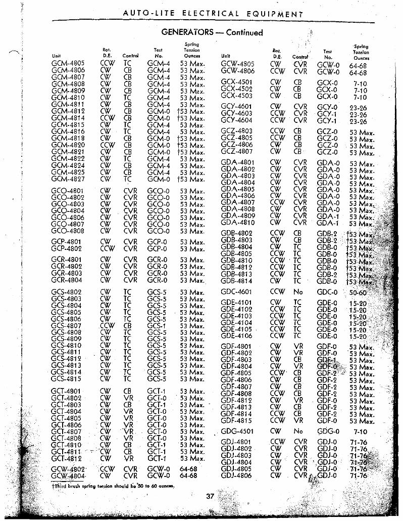
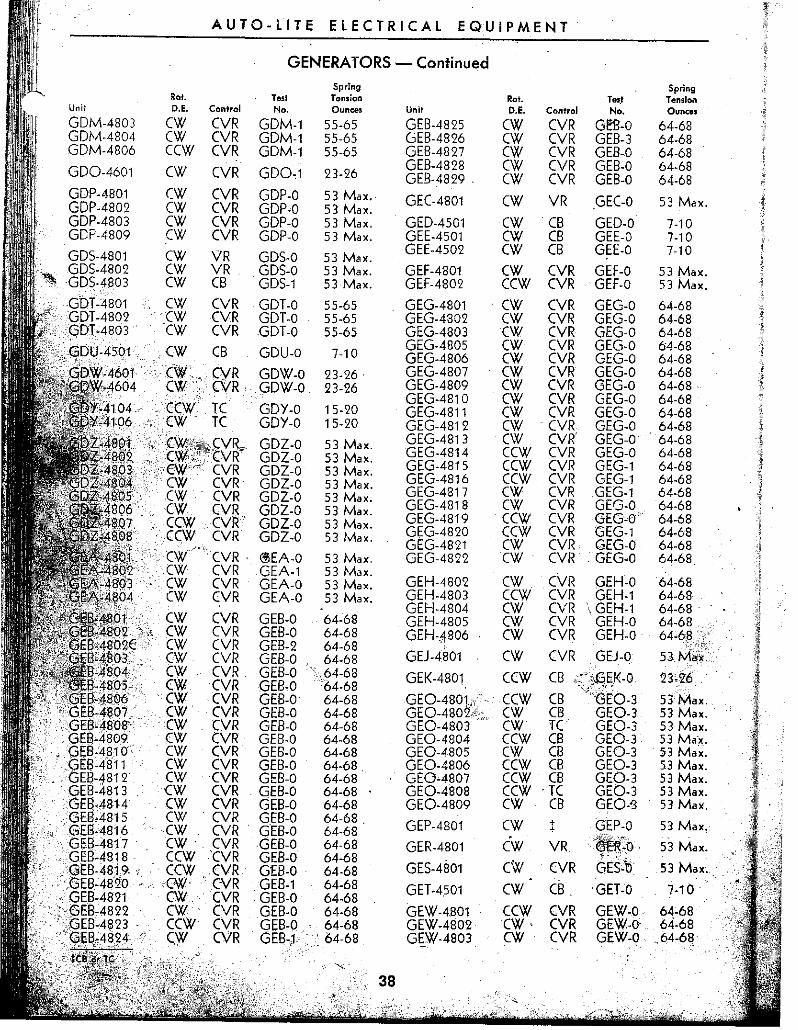
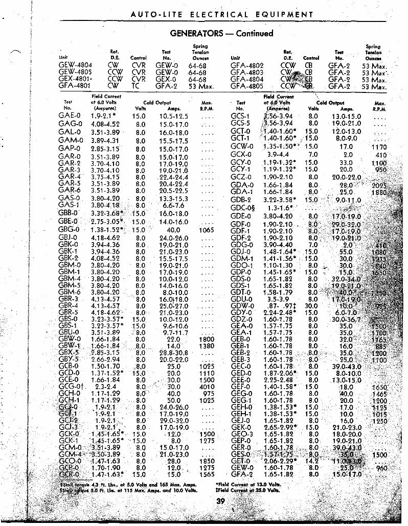
Description pnd Function Maintenance Procedure Numerical Index.. .. ............ .. Overhaul Procedure .... Test Specifications ..
IGNITION COILS ...
RELAYS AND REGULATORS
CB, CSA and RA Circuit Breakers
Description and Function, .... .. Maintenance Procedure .......... . Test Specifications
TC Regulators
Description and Function ........ , .... Maintenance Procedure ..
............. ,12 . .. 25
............ 26
................ 29
. .. 30 ............. 39
. .. 40
...40
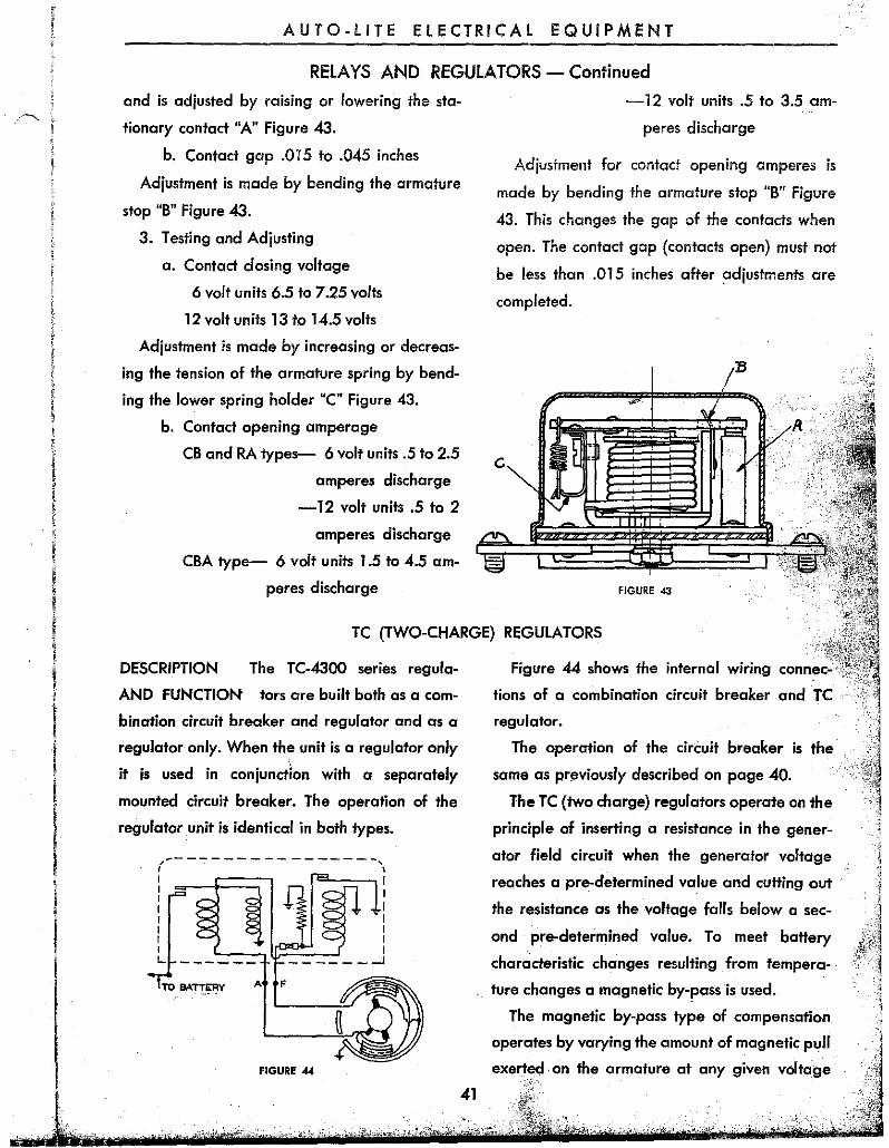
41
..41
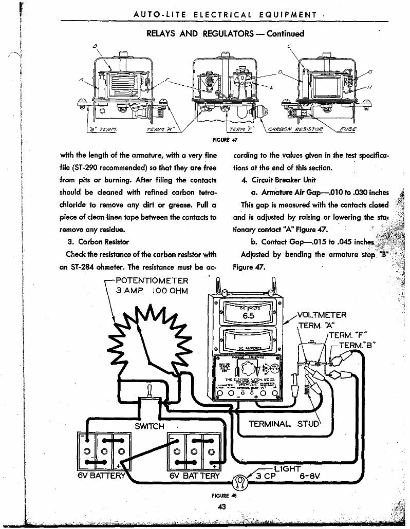
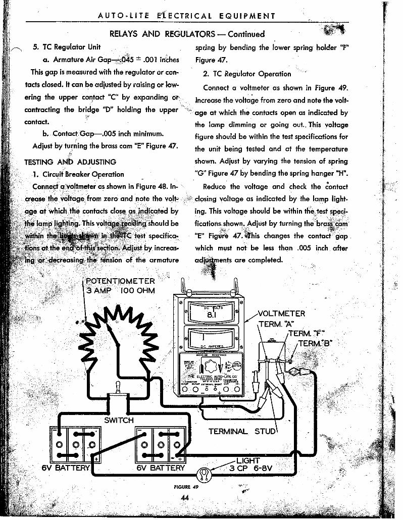
.. .... 42 Tasting and Adjusting .. . .. ................ 44 Test Specifications ......................... .
Car Test.. Description and Function ........... 46 Maintenance Procedure ... , ......................... .48-. Numerical Index ...................................... 65
".1 Testing and ·Adjusting ........................ ' ... 53 Test Specifications... ....... ....... . .... -.. ~; .68
VRA, VRC, VRG, VRH "nd ,VRY Regulators ' . ~~
Car Test .................................... 47, Descrip~ion an'd Function .. '............ : .... .:~;.;56>,. ," . Maintenance Procedure ................... "'i;; '.' ~56.,-" Numericallnde~ ........... ·.-... : ......... , ............ , .. t~.t'5",:, Testing and Adjusting ..... " ................ :,: .... ~,,61, T esf Specifica~ions ....................... -;. ~ .68;
'''~
STARTING MOTORS' ANDl;iWITCHES
Description and Function .............. ;; .. . Maintenance Procedure .... . Motor Test Specifi~otic)'ns .... _ ..... Overhaul Proce~u're ...... .,;::.)' .. ". ":.:':'::''':<'~ Switch Tests and Spedficat.ions ... :·:·~: '~J'.;"'"
WINDSHIELD WIPERS "
EW and' EWA Series: .. EWB and EWC Series EWD and EWE Series
-,'I\'.
. ....... , .. _.1:.::.
Test Specifications ... ,. ........................ , ..
Complete technical information on all Auto-lile equipm~nf'is included 'in the Service Manual Binder which is in. the possession of every Auto-Lite Service, " ,." Station. , Should additi~nal. information' b~l'equ.i;~d on any of the equipmerit~o,!ered in this manual or l)n any Auto:htiLunit 'not covered in this:book It c9r1!je,
obtained f~om any Official A~t.,~l:ite SerVice 'Station, -! .""'-.
THE i.~TRIC AUTO-LITE COMPANY' , tl1?"'.' :. •• /" .
PARTS AND SERVICE Dlvrsl9N. "
, J;OLEp,O, .mI16, U.S.A. d • ::' , ,
•
.".
"
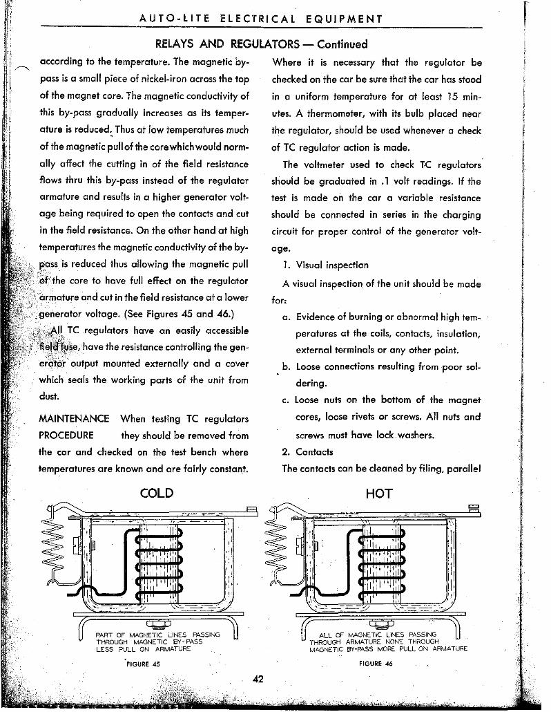
AUTO-LITE RICAl EQUIPMENT
SERVICE TOOLS In order to meet the demands for accurate re
sults automotive service men must be skilled in
the art of measurement. This includes the use <;If
the following essential service station tools.
1. Voltmeter 7. Vacuum Gauge
2. Ammeter 8. Compression Gauge
3. Ohmeter 9. Coil Tester
4. Timing Li9ht 10. Micrometers
5. Gap Gauges 11. Distributor Test Fixture
6. Feeler Gouges 12. Condenser Tester
Several of these units have been developed to
Auto-Lite specifications as fine precision instru
ments while others may be obtained from several
dependable sources.
In handling electrical measuring instruments
it should be 'remembered that they are extremely
sensitive and delicately balanced. They should
not, therefore, be subjected to sudden shocks nor
should they be subjected to excessive vibration.
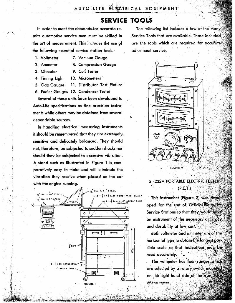
A sland such os illustrated in Figure 1 is. com
paratively easy to make and will eliminate the
vibration they receive when placed on the car
with the engine running.
2- -i X20 SETSCREWS
I" ANGLE IRON
FIGURE 1
The following list includes a ,few of the
Service Tools that are available. Those included,
are the tools which are required for aocu,dll,'"
adjustment service.
,
ST -232APORTABLE EL.EC,.RXCT' S'l 5;J;Ell{l ,. (P.E.i.) '" -
, This instrument (Figure ~) WCI$j~j
oped for the" use,: of. :'( )ffiiri .. d
Service Statiorisso that fh~Y . . ~ .. an instrument of the ne.:esspry a.'~,~~irp<~,"~~ii
and durability at I,ow cost,,'
Both voltm!lter and am!l1.~'~.r a.r,eohhl!l,;
horizontaT typet~ ob'';,;n'
sible scale so that inc:liecltil)ns, riiiii,,::)bjl:,
read accur~tely. " . ,
The volt!l1eter has follr' rai~g,.s,:Jwlffal: . . . are selectedbya rotaty:''''-'''''t
on the right hari~side . of ,
AUTO-LITE 'ELECTRICAL EQUIPMENT
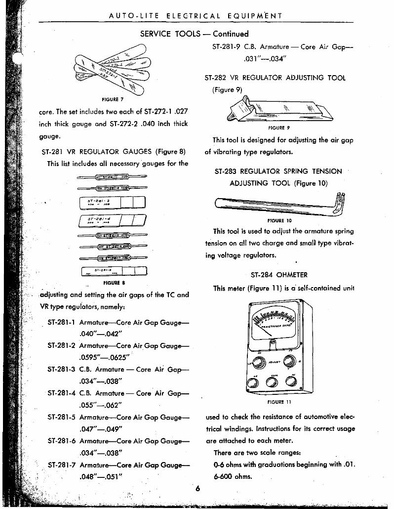
SERVICE TOOlS - Continued
0- 5 volt scale for testin~ hiSh resistances and
electrical devices operating at low volt
ages.
0-10 volt scale for general use on 6 volt
circuits.
~-20 vqlt scale for general use on 12 volt
circuits.
0-50 volt scale for general use on 24 and 32
volt circuits.
For the 0-10 volt scale there are 100 divisions
so that each represents .1 volts. Accuracy of the
~oltmeter is held within 1 % of all parts of the
, scale, except between 6 and 9 volts where it is
held to clr % accuracy. This is necessary as this
latter portion of the scale is the most commonly
: ,;lil5ed;,;jn testing 6 volt circuits. ·""[Ji"-<-('·';('" :~-"
The ammeter has two scales:
3-0-10 ampere scale for testing low current
draw.
15-0-50 ampere scale for general use in test
ing automotive circuits.
Depressed zero scales are built into the instru
, ment to avoid the necessity of changing the am
- meter connections to obtain negative readings
s,uch as the amperes discharge required to open
circuit breakers.
The accuracy of the ammeter is held within 2%
of full scale deflection.
/>.. t ohm rheostat of 50 ampere capacity is
included in this instrument for use in setting volt
age to test specifications.
There are four current carrying binding posts'
on the instrument: The 'first one on the right hand
side, marked "Resistance In," is connected to the
rheostat and is in series with the positive terminal
of the ammeter.
" • Th" second binding post, marked "Resistance
4
Out" is a direct connection to the positive term
inal of the ammeter without passing through the
rheostat.
The third binding post is connected to the
negative terminal of the ammeter for the 50
, ampere scale.
The fourth binding post is connected to the
negative ammeter terminal for the 10 ampere
scale.
Two small binding posts are provided between
the second and third current carrying binding
posts for the use of external shunts. The following
FIGURE 3
shunts (Figure 3) are available with calibrated
leads for connections to the P.E.T. Set:
100 ampere capacity-Part Number ST -232A-2
200 ampere capacity-Part Number ST-232A-3
500 ampere capacity-Part Number ST-232A-1
1000 ampere capacity-Part Number ST -232A-4
The voltmeter leads are permanently attached
to the instrument and are 27" long with alligator
clips on the ends for ease in making connections.
The positive lead is colored red and the negative
lead is black.
Ammeter leads are No.8 flexible cable 37"
long and have pin terminals on one end for
connecting to the current carrying binding posts
and special clips on the other end. The positive
lead is red and the negative black. The ammeter
lead clips have a long tooth on each carner so
that they may be securely connected to wires
with screw holes in the terminals.
AUTO-LITE ELECTRICAL EQUIPMENT
SERVICE TOOLS - Continued
GAlkil: TeST SET ....... c,.". _ ....... , .... c.1' .""~'.II
T>It rutc.,."IC AUTO-LITe til ......... t ........ _ • ...... -~,-1:0"".'51'_
TC-430SAf 6 1 I.S5 5 *Ohmic re5istanc~ is the marked volue with a toterance of ± 5%. TC-4309Af 1.85 6 1 5 tNo circuit breaker.
TEST TC REGULATOR TEST DATA
CIRCUIT BREAKER 1 2 3 111-12~
.01 0"-.030" .0 15" ~.045"
13.0-13.5 .5-2.0
Resistance 'of Voltage Winding ... . Armature Air Gap ....................... . Contact Point Gap ....................... . Point Closing Volts .................... ~ •. Point Opening Amps. Discharge ..
VOLTAGE. REGULATOR Resisl!Jl1~e of Winding ................. . ArmatWe Air Gap ........................ .
.. Contact' Point Gap ...................... ::· .. . High to Low Charge ................... .
Resistance of Voltage Winding ....................... ;~:.: ......... . Armature Air ~p ........ ;~ ............................................... . Contact Point Gap .................. ;', ..................................... . Point Volts... ..• . ........................ .' ..... .
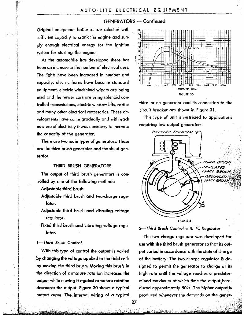
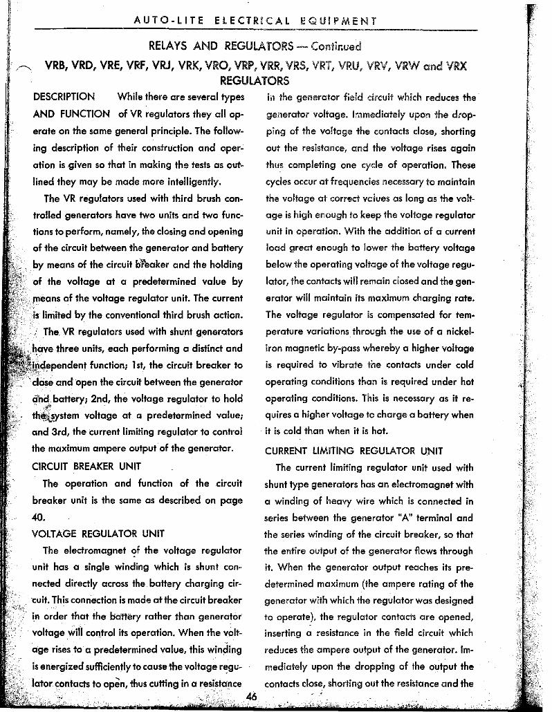
ation is given so that in making the tests as out
lined they may be made more intelligently.
The VR regulators used with third brush con
trolled generators have two units and two func
tions to perform, namely, the closing and opening
of the circuit between the generator and battery
by means of the circuit breaker and the holding
of the voltage at a predetermined value by
.. /lleans of the voltage regulator unit. The current
limited by the conventional third brush action.
The. VR regulators used with shunt generators
three units, each performing a distinct and
'i~cle~,endent function; 1 st, the circuit breaker to
and open the circuit between the generator
and battery; 2nd, the voltage regulator to hold . #' -
thi~ystem voltage at a predetermined value;
and 3rd, the current limiting regulator to control
the maximum ampere output of the generator.
CIRCUIT BREAKER UNIT
The operation and function of the circuit
breaker unit is the same as described on page
40.
VOLTAGE REGULATOR UNIT
The electromagnet ,?f the voltage regulator
unit has a single winding which is shunt con
nected directly across the battery charging cir
·cuit. This connection is made at the circuit breaker
. . in order that the battery rather than generator
voltage win control its operation. When the vOlt
age rises to a predetermined value, this winding
is energized sufficiently to cause the voltage regu-
in the generator field circuit wnich reduces the
generator voltage. Immediately upon the drop
ping of the voltage the contacts close, shorting
out the resistance, and the voltage rises again
thus completing one cyde of operation. These
cycles occur at frequencies necessary to maintain
the voltage at correct vaiues as long as the volt
age is high enough to keep the voltage regulator
unit in operation. With the addition of a current
load great enough to lower the battery voltage
below the operating voltage of the voltage regu
lator, the contacts will remain closed and the gen
erator will maintain its maximum charging rate .
The voltage regulator is compensated for tem
perature variations through the use of a nickel
iron magnetic by-pass whereby a higher voltage
is required to vibrate the contacts under cold
operating conditions than is required under hot
operating conditions. This is necessary as it re
quires a higher voltage to charge a battery when
it is cold than when it is hot.
CURRENT LIMITING REGULATOR UNIT
The current limiting regulator unit used with
shunt type generators has an electromagnet with
a winding of heavy wire which is connected in
series between the generator "A" terminal and
the series winding of the circuit breaker, so that
the entire output of the generator flows through
it. When the generator output reaches its pre
determined maximum (the ampere rating of the
generator with which the regulator was designed
to operate), the regulator contacts are opened,
inserting a resistance in the field circuit which
reduces the ampere output of the generator. Im
mediately upon the dropping of the output the
.Iator contacts to open, thus cutting in a resistance contacts dose, shorting out the resistance and the c 46
AUTO-LITE ELECTRICAL EQUIPMENT
RELAYS AND REGULATORS - Continued
output rises completing one cycle of operation.
These cycles occur at sufficiently high frequency
so that the output is limited to a predetermined
maximum.
CAR TEST
NOTE-BEFORE ANY WORK IS DONE ON THE
REGULATOR THE FOLLOWING CONDI
TIONS SHOULD BE CAREFULLY CHECKED
AND CORRECTED IF AT FAULT:-
1. WIRING FROM GENERATOR TO REGU
LATOR PROPERLY CONNECTED.
2. HIGH RESISTANCE CONNECTIONS IN
THE CHARGING CIRCUIT. THIS SHOULD
BE CHECKED WITH AN ACCURATE READ
ING VOLTMETER AND INSPECTED ME
CHANICALLY FOR POORLY SOLDERED
TERMINALS AND LOOSE OR CORRODED
CONNECTIONS.
3. GENERATOR PERFORMANCE WITHOUT
THE REGULATOR IN THE CIRCUIT OPER
ATING ACCORDING TO SPECIFICA
TIONS.
4. THAT THE REGULATOR IS THE ONE DE-
. SIGNED FOR THE GENERATOR WITH
WHICH IT IS OPERATING. THESE REGU
LATORS WILL FUNCTION SATISFACTOR
ILY ONLY WHEN INSTALLED WITH THE
GENERATOR DESIGNED TO OPERATE IT.
ALSO BATTERY CONDITION AFFECTS
REGULATOR OPERATION. AN OLD BAT
TERY, ONE PARTIALLY CHARGED OR
ONE SUBJECTED TO EXCESSIVE HEAT
WILL CAUSE HIGH CHARGING RATE;
WHILE ONE SUBJECTED TO EXCESSIVE
COLD, HARD PLATES, HIGH RESISTANCE
SEPARATORS AND SULPHATION WILL
CAUSE LOW CHARGING RATE. THE
OPEN CIRCUIT TERMINAL VOLTAGE OF
THE BATTERY AS WEll AS ITS SPECIFIC
GRAVITY SHOULD BE CHECKED. THE
CONDITION OF THE BATTERY AS TO
CAPACITY, LEAKAGE, ETC. SHOULD BE
CHECKED BY SEPARATE TEST AS SPECI
FIED BY THE BATTERY MANUFACTURER.
The equipment needed for testing on the car
includes an accurate indicating ammeter gradu
ated in 1 ampere readings with heavy short
leads, an accurate indicating voltmeter gradu
ated in .1 volt readings and a reliable ther-
mometer.
The resistance of the test ammeter must not
exceed .1 volts at 10 amperes or.01 ohms.lnstru- ..
ments which have resistance higher than this will
make it impossible to check or adjust the
with the necessary accuracy.
The drop in voltage from the regulator to
battery or from the generator to the regulatot
must not exceed .1 volt when the generator is
charging 10 amperes. At this same charging
rate the voltmeter should not show a reading
when measured from the regulator base to the
battery ground post, the generator frame to the
regulator base or from the generator frame to
d the battery groun post. (, r: !/ /5'-.
[Iii • • l .- jl' .
0
~' ,,~ • [ ,<= J @ I~ "1I'loh@ • )
"-2./ . .;;:~F"'~ 15 Tr;1io
Jill -~
=
I " ~F
eATTUY -"'
.~ U
FIGURE 50
47
f::
AUTO-LITE elECTRICAL EQUIPMENT
RELAYS AND REGULATORS - Continued
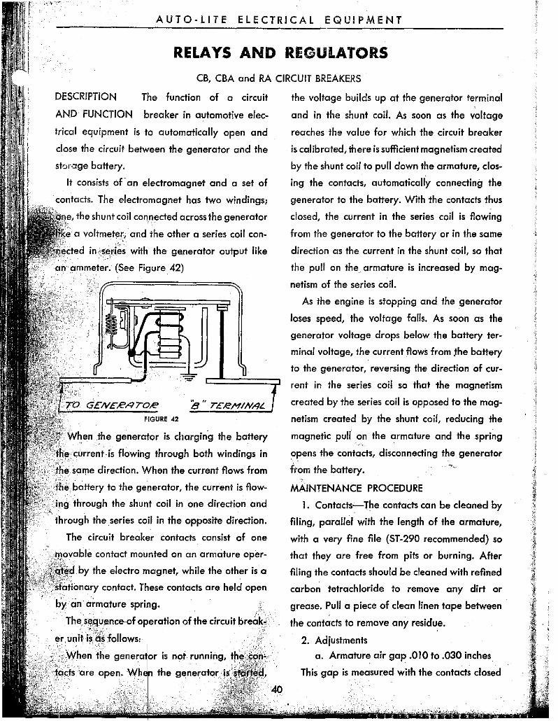
~ Connections: Disconnect the wire from the reg- battery. (This load may consist of a bank of
Aator "B" terminal. Connect one ammeter lead to standard head light bulbs or a carbon pile rhea-
the regulator "B" terminal and the other am- stat.) If the current limiting regulator is function-
meter lead to the lead removed from this terminal ing correctly, the test ammeter will show a read-
as shown in Figure 50. One voltmeter lead should ing of the maximum amperes shown on the name
be connected to the regulator "B" terminal on the plate of the regulator with an allowed variation
regulator side of the ammeter connection, while of ± 5%.
the other voltmetEir lead is to be connected to the If the unit does not operate according to speci-
terminal marked "GO" or to the,.base of the regu- flcations it should be removed from the car and
lator.·{lf the connections are not. made in this . thoroughly checked and adjusted.
manrier, false readings will be oflltained due to . .,~
. voltage loss in the current connect,'!,,,s.}
·fhe thermameter should be placed,.sa· that its
bulb Is approximately two inches from the side af
"the regulator. It must not touch the regulator.
Battery: This mU,st read 1.275 ta 1.280 specific
gfCl,vity,lf the car battery is discharged, substitute
. .tel1lPorarily for test purposes a fully charged bat-
tery .in good condition of the same type and
'" ·capacity.
Test: Start the engine and set the throttle for
a speed equivalent to approximately 30 M.P.H.
Run the engine for not leu than 15 minutes with
the car hood up before taking meter readings.
. With a generator charge of 10 amperes the volt
meter should show a re"ding according to the
specification figures given for the regulator under
test at the temperature shown by the thermam
eter. With readings according to these figures,
the voltage regulator unit can be passed as func
tioning correctly. See pages 65 to 70 for com
plete test data.
To test the current limiting regulator, the same
connections as notet above are used. Add an
.,electricalload ,pf a current value in excess of the
amperes noted on the name plate of the regu
lator at a paint between the car ammeter and the
48
MAINTENANCE PROCEDURE
VISUAL INSPECTION
Before making any tests or adjustments it is
recommended that a close visual inspectian be
given the regulator, with special emphasis being
paid to the following points:
1. Broken regulator seal.
2. Evidence of burning or abnormal high
temperature at the coils, contacts, insula
tion, external' terminals or ,.any other
point. (It is suggested that fhis test be
made with a magnifying glass.)
3. Loose connections which result from poor
soldering.
4. Loose nuts on the bottom of the magnet
cores, loose rivets or screws. 'All nuts and
screws must have lock washen.
5. Loose contacts.
6. Misalignment of contacts.
7.' Bent armature either at the./~ontact or
hinge end. (The armature should be per
fectly straight from one end ta fhe other.)
8. Magnet yoke bent.
9. Bent armature hinges.
10. Reversed bimetal hinges an the circuit
AUTO-LITE ELECTRiCAL EQUIPMENT
RELAYS AND REGULATORS - Continued
breaker unit. (When correctly installed
the brass side must be up.)
II. Stripped or crossed threads on any screw
or nut.
12. Corrosion due to salt or acids.
13. Broken ground straps.
14. Evidence of water having been inside of
cover.
15. Incorrect, bent or distorted armature
spring. In case of doubt it is recommended
that the spring be replaced.
16. Broken or altered carbon resistors.
17. Broken gaskets. ,.(.
18. Incorrect wiring connections between
units.
See pages 65 to 70 for complete test data on
VR type r.agulatars.
CONTACTS
The contacts should be cleaned by filing, paral
lel with the length of the armature, with a very
fine file (ST -290 recommended) so that they are
free from pits or burning. After filing the con
tacts should be cleaned with refined carbon tet-
FIGURE 51
rachloride to remove any dirt or grease. Pull a
clean piece of linen tape between the contacts to
remove any residue.
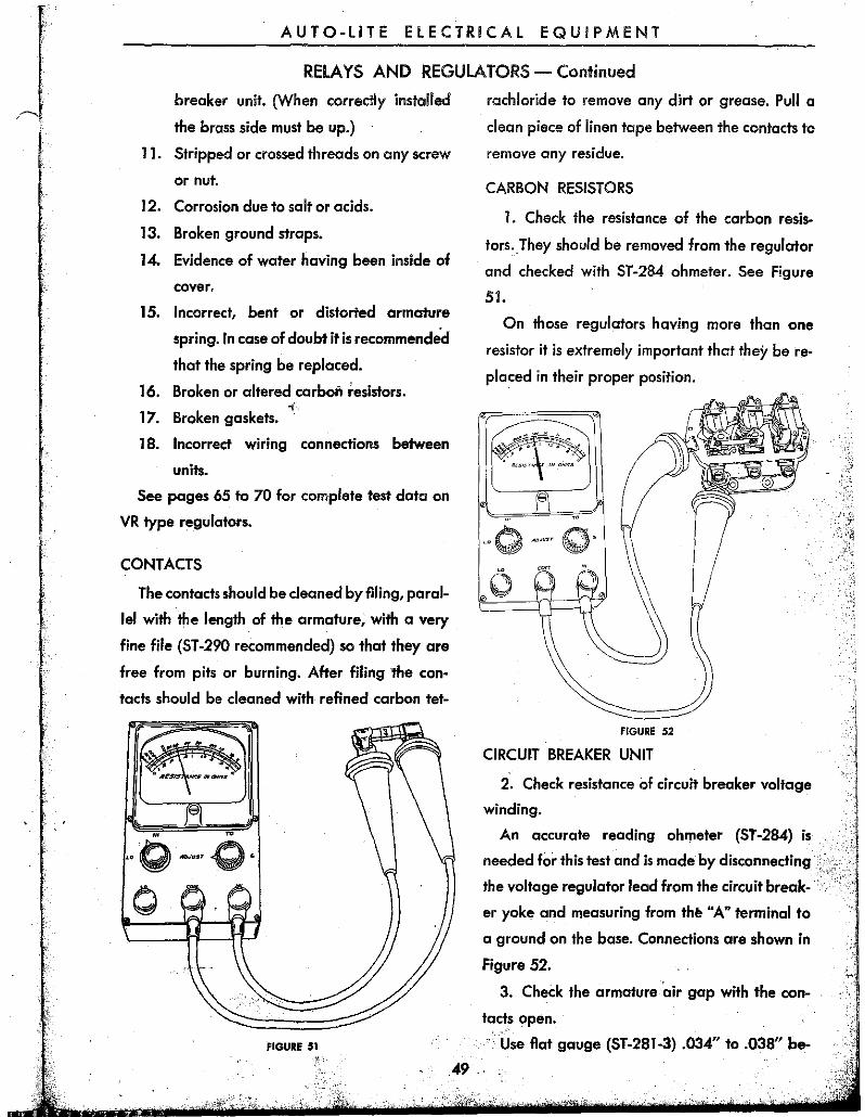
CARBON RESISTORS
I. Check the resistance of the carbon resis
tors. They should be removed from the regulator
and checked with ST-284 ohmeter. See Figure
51.
On those regulators having more than one
resistor it is extremely important that they be re
placed in their proper position.
'0 Q ,0,"" ".
o
FIGURE 52
CIRCUIT BREAKER UNIT
2. Check resistance of circuit breaker voltage
Winding.
An accurate reading ohmeter (ST -284) is
needed for this test and is made by disconnecting
the voltage regulator lead from the circuit break
er yoke and measuring from thl! "A" terminal to
a ground on the base. Connections are shown in
Figure 52.
3. Check the armature 'air gap with the con
tacts open.
"Use flat gauge (ST-281-3) .034" to .038" be-,49.,
AUTO-LITE ELECTRICAL EQUIPMENT
RELAYS AND REGULATORS - Continued
rlil l " 'I ,
FIGURE 53
tween the magnet core and the armature as close
to the hinge as possible as shown in Figure 53 ..
e
FIGURE 54
. Adjustment of the air gap is made by bending
•.. the armature stop "A" Figure 54 making sure that
FIGURE 5S.
50
it does not rub against the side of the armature.
On early production regulators the armature
stop was at the end of the armature as shown in
Figure 55. To adjust bend this stop "B" being sure
that it does not rub against the end of the arma-
FIGURE S6
ture. Other early regulators had the armature
stop in the center as is shown in Figure 56. On
this type bend the stop "C" being sure it does not.
rub against the side of the slot.
c
FIGURE fil
On those applications where an indicating
lamp is used instead of an ammeter the regulator
circuit breaker unit has·a second set of contacts.
To adjust the armature air gap on this type af
unit bend the upper contact bracket "C" Figure
57 as required. BE SURE THAT THE BRACKET
AUTO·L1TE ELECTRICAL EQUIPMENT
RELAYS AND REGULATORS - Continued
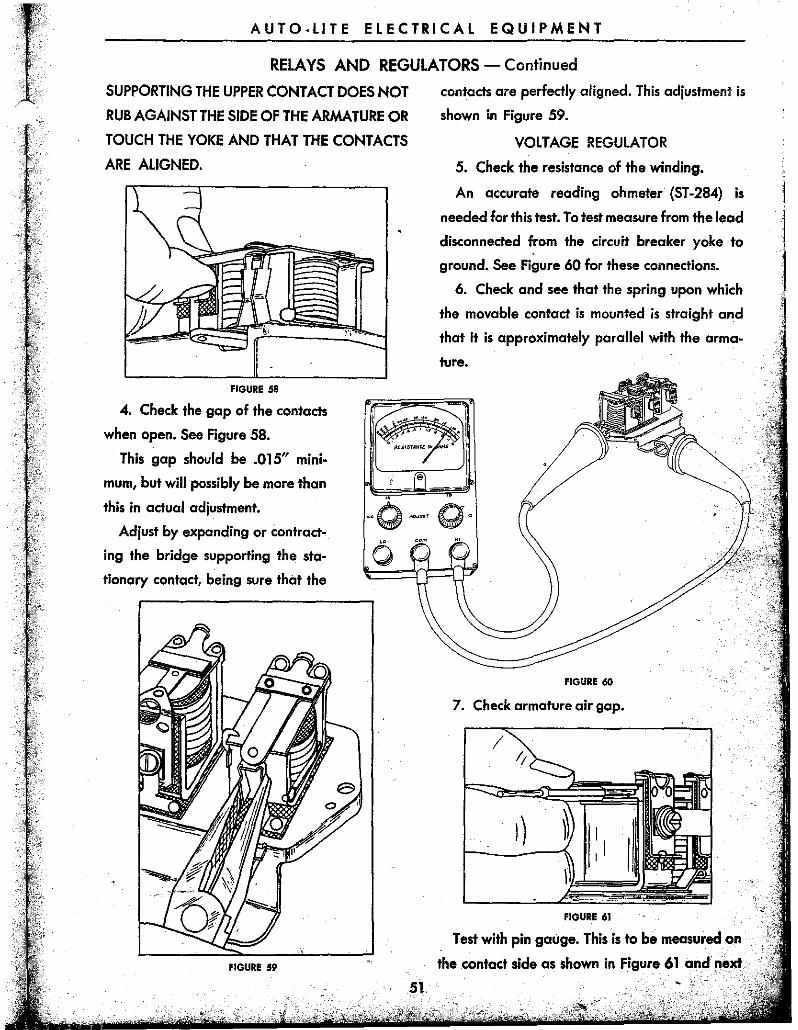
SUPPORTING THE UPPER CONTACT DOES NOT
RUB AGAINST THE SIDE OF THE ARMATURE OR
TOUCH THE YOKE AND THAT THE CONTACTS
ARE ALIGNED.
FIGURE 58
4. Check the gap of the contacts
when open. See Figure 58.
This gap should be .015" mini·
mum, but will possibly be more than
this in actual adjustment.
Adjust by expanding or contract.
ing the bridge supporting the sta·
tionary contact, being sure that the
FIGURE 59
contacts are perfectly aligned. This adjustment is
shown in Figure 59.
VOLTAGE REGULATOR
5. Check the resistance of the winding.
An accurate reading ohmeter (ST·284) is
needed for this test. To test measure from the lead
disconnected from the circuit breaker yoke to
ground. See Figure 60 for these connections.
6. Check and see that the spring upon which
the movable contact is mounted is straight and
that it is approximately parallel with the arma·
ture.
FIGURE 60
7. Check armature air gap.
/
FIGURE 61
Test with pin gauge. This is to be measured on
the .contact side as shown in Figure 61 apd .nel!f ..
AUTO-LITE ElECTRICAL EQUIPMENT
RELAYS AND REGULATORS - Continued
FIGURE 62
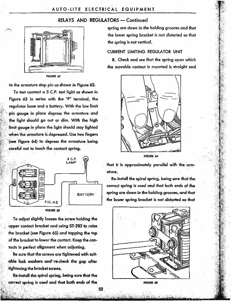
to the armature stop pin aBhown in Figure 62.
To test connect a 3 C.P. test light as shown in
Figure 63 in series with the "F" terminal, the
regulator base and a battery. With the low limit
pin. gauge in place depress the armature and
the light sh~uld go out or dim. With the high
limit gauge in place the light should stay lighted
wilE'" 'the armature is depressed. Use two fingers
(see Figure 64) to depress the armature being
careful not to touch the contact spring.
o.
·0 FIG.42
FIGURE 63
3 c.P. LAMP
BATTERY
To adjust slightly loosen the screw holding the
upper contact bracket and using ST-2B2 to raise
the bracket (see Figure 65) and tapping the top
of the bracket to lower tbe contact. Keep the con
tacts in perfect alignment when adjusting.
Be sure that the screws are tightened with suit
able lock washersand..,.e;.check the gap after
tightening the bracket screws.
~E!-install the spiral spring, being sure that the
correct spring is used and that both ends of the
52.
spring are down in the holding grooves and that
the lower spring bracket is not distorted so that
the spring is not vertical.
CURRENT LIMITING REGULATOR UNIT
B. Check and see that the spring upon which
the movable contact is mounted is straight and
FIGURE 64
that it is approximately parallel with the. arm
ature.
Re-install the spiral spring, being sure that the
correct spring is used and that both ends of the
spring are down in the holding grooves, and that
the lower spring bracket is not distorted so that
fiGURE 65
AUTO-LITE ELECTRICAL EQUIPMENT
RELAYS AND REGULATORS - Continued
the spring is not vertical.
9. Check armature air gap.
Test with pin gauge. This is to be measured on
the contact side as shown in Figure 61 and next
to the armature stop pin as shown in Figure 62.
To test connect a test light as shown in Figure
63 in series with the "F" terminal, the regulator
base and a battery. With the low limit pin gauge
in place depress the armature and the light
should go out or dim. With the high limit gauge in
place the light should stay lighted when the arm
ature is depressed. Use two fingers (see Figure
64) to depress the armature being careful not to
touch the contact spring.
To adjust slightly loosen the screw holding the
upper contact bracket and using ST-282 to raise
the bracket (see Figure 65) and tapping the top
of the bracket to lower the contact. Keep the con
tacts in perfect alignment when adjusting.
Be sure that the screws are tightened with suit
able lock washers and re-check the gap after
tightening the bracket screws.
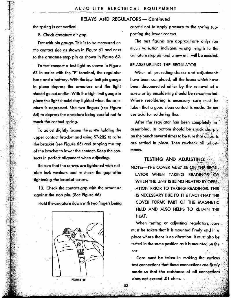
10. Check the contact gap with the armature
against the stop< pin. (See Figure 66)
Hold the armature down with two fingers being
FIGURE 66
53
careful not to apply pressure to the spring sup
porting the lower contact.
The test figures are approximate only; too
much variation indicates wrong length to the
armature stop pin and a new unit will be needed.
RE-ASSEMBlING THE REGULATOR
When all preceding checks and adjustments
have been completed, all the leads which have
been disconnected either by the removal of a
screw or by unsoldering should be re~connected.
Where resoldering is necessary care must be
taken that a good cleon contact is made. Do not
use acid for soldering flux.
After the regulator has been completely re
assembled, its bottom should bestfllck sharply
on the bench several times to be sure thar~lrparts« are settled in place. Then re-check < all adjust
ments.
TESTING AND
LATOR WHEN TAKING
WHEN THE UNIT IS BEING HEATED BY OPER.
ATiON PRIOR TO TAKING READINGS. THIS
IS NECESSARY DUE TO THE FACT THAT THE
COVER FORMS PART OF THE MAGNETIC
FIELD AND ALSO HELPS TO RETAIN THE
HEAT.
When testing or adjusting< regulators, care ,
must be token that it is mounted firmly ahd in a
place where there is no vibration. It must also be
tested in the same position as it is mounted on the
car.
Care must be taken in making the various
test connections that these connections are firmly
made so that the resistance of all connections
does not exceed .01 ohms. <
AUTO-LITE ELECTRICAL EQUIPMENT
RelAYS AND REGULATORS - Continued
HEAT THE REGULATOR BY OPERATING IT
FOR 15 MINUTES WITH THE GENERATOR
CHARGING 10 AMPERES. WHILE HEATING
HAVE THE COVER ON THE UNIT.
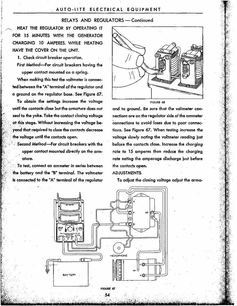
1. Check circuit breaker operation.
First Method-For circuit breakers having the
upper contact mounted on a spring.
)1
When making this test the voltmeter is connec- I ted between the "A" terminal of the regulator and
a ground on the regulator base. See Figure 67.
To obtain the settings increase the voltage
until the contacts close but the armature does not
seal to the yoke. Take the contact closing voltage
at. this stage. Without increasing the voltage be
yond thatcrequired to close the contacts decrease
. the voltage until the contacts open.
: Second Method-For circuit breakers with the
upper contact mounted directly on the arm
ature.
To test, connect an ammeter in series between
the battery and the "B" terminal. The voltmeter
is connected to the "A" terminal of the regulator
• ill ><rom ]
t< -"'''' jl e
'" -··-IOl-: ('5 ~... , .. ~.~;. ~'.
i~~ff·'5~ JI
.... Illl,r ))
fr+ 'fr. "-
- ' ~
BATTERY .
FIGURE 68
and to ground. Be sure that the voltmeter con-
nections are on the regulator side of the ammeter
connections to avoid loses due to poor connec
tions. See Figure 67. When testing increase the
voltage slowly noting the voltmeter reading just
before the contacts close. Increase the charging
rate to 15 amperes then reduce the charging.
rate noting the amperage discharge just before
the contacts open.
ADJUSTMENTS
To adjust the closing voltage adjust the arma-
~IL
IT(~ -;== A
[,'Q.
~ , GO.
31 @
8 r(
~ ~
(if HEADPHONE
I~ I IL
,0
I II ~ I~ ••
AO
I if
fiGURE 67
54
AUrO-lITE ELECTRICAL EQUIPMENT
RELAYS AND REGULATORS - Continued
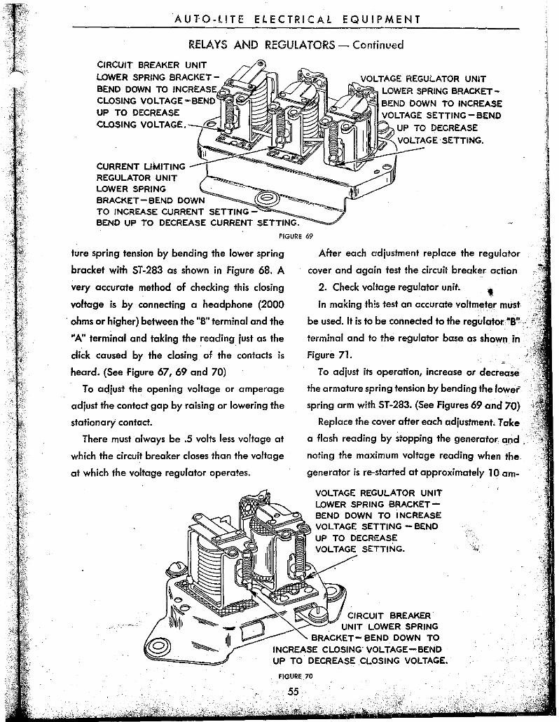
CIRCUIT BREAKER UNIT LOWER SPRING BRACKETBEND DOWN TO INCREASE ='-~ CLOSING VOLTAGE-BEND UP TO DECREASE CLOSING VOLTAGE.
CURRENT LIMITING REGULATOR UNIT LOWER SPRING
TO INCREASE CURRENT SETTING;:::-~;;;;"_ BEND UP TO DECREASE CURRENT SETTING.
LOWER SPRING BRACKETBEND DOWN TO INCREASE
UP TO DECREASE VOLTAGE SETTING.
FIGURE 69
ture spring tension by bending the lower spring
bracket with ST-283 as shown in Figure 68. A
very accurate method of checking this closing
voltage is by connecting a headphone (2000
. ohms or higher) between the "S" terminal and the
"An terminal and taking the reading. just as the
click caused by the closing of the contacts is
heard. (See Figure 67, 69 and 70)
To adjust the opening voltage or amperage
adjust the contoct gap by raising or lowering the
stationary contact.
There must always be .5 volts less voltage at
which the circuit breaker closes than the voltage
at which the voltage regulator operates.
After each adjustment replace the regulator
cover and again test the circuit break~r actiCln
2. Check voltage regulator unit. , In making this test an accurate voltmeter must
be used. It is to be connected to the regulator"a"
terminal and to the regulator base as shown in
Figure 7l.
To adjust its operation, increase or decrease
the armature spring tension by bending the lower
spring arm with ST -283. (See Figures 69 and 70)
Replace the cover after each adjustment. Take
a flash reading by stopping the generator and , .
noting the moximum voltage reading when the
generator is re-started at approximately 10 am-
VOLTAGE REGULATOR UNIT LOWER SPRING BRACKETBEND DOWN TO INCREASE VOLTAGE SETTING -BEND
":~~,II CIRCUIT BREAKER " UNIT LOWER SPRING
BRACKET- BEND DOWN TO INCREASE CLOSING- VOLTAGE-BEND UP TO DECREASE .CLOSING VOLTAGE.
FIGURE 70
55
, ,
I
AUTO-LITE ELECTRICAL EQUIPMENT
RELAYS AND REGULATORS - Continued
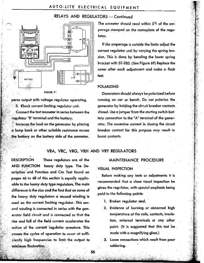
, "c:::J" @
~, @ ,
II
JI
IL
!3ATTEIi'Y
FIGURE 71
peres output with voltage regulator operating.
3. €heck current limiting regulator unit.
Connect the test ammeter in series between the
regulator "S" terminal and the battery.
,,' Increase,the load on the generator by placing
a lamp bank or other suitable resistance across
,f/le battery on the battery side of the ammeter.
The ammeter should reod within 5% of the am
perage stamped on the nameplate of the regu
lator.
If the amperage is outside the limits adjust the
current regulator unit by varying the spring ten
sion. This is done by bending the lower spring
bracket with ST-283. (See Figure 69) Replace the
cover after each adjustment and make a flash
test.
POLARIZING
Generators should always be polarized before
running on car or bench. Do not polarize the
generator by holding the circuit breaker contacts
closed. Use a jumper from the starting switch bat
tery connection to the "A" terminal of the gener
ator. The excessive current in closing the circuit
breaker contact for this purpose may result in
burnt contacts.
VRA, VRC, VRG, VRH AND VRY REGULATORS
DESCRIPTION
AND FUNCTION
These regulators are of the
heavy duty type. The De-
scription' and Functian and Car Test found on
pages 46 to 48 of this section is equally applic
able to the heavy duty type regulatars. The main
difference is the size and the fact that on same of
the heavy duty regulators a second winding is
used on the current limiting regulator. This sec
ond winding is connected in series with the gen
erator field circuit and is cannected so that the
rise and fall of the field current accelerates the
action of the curreiit'regulator armature. This
causes the cycles of aperation to occur at suffi
ciently high frequencies to limit the output ta
minimum fluctu(1ti()~,
56
MAINTENANCE PROCEDURE
VISUAL INSPECTION
Sefore making any tests or adjustments it is
recommended that a close visual inspection be
given the regulator, with special emphasis being
paid to the following paints:
1. Sroken regulatar seal.
2. Evidence of burning or abnormal high
temperature at the coils, contacts, insula
tion, external terminals or any other
point; (It is suggested that this test 'be ,
made with a magnifying glass.)
3. Loose connections which result from poor
soldering.
AUTO·L1TE ELECTRICAL EQUIPMENT
RELAYS AND REGULATORS - Continued
4. loose nuts on the bottom of the magnet
cores, loose rivets or screws. All nuts and
screws must have lock washers.
5. Loose contacts.
6. Misalignment of contacts.
7. Bent armature either at the contact or
hinge end. (The armature should be per·
fectly straight from one end to the other.)
8. Magnet yoke bent.
9. Bent armature hinges ..
10. Reversed bimetal hinges on the circuit
breaker unit. (When correctly installed
the brass side must. be up.)
11. Stripped or crossed threads on any screw •
or nut.
12. Corrosion due to salt or acids.
13. Evidence of water having been inside of
cover.
14. Incorrect, bent or distorted armature
spring .In case of doubt it is recommended
that the spring be replaced.
15. Broken or altered carbon resistors.
16. Broken gaskets.
17. Incorrect wiring connections between
units.
18. Shunt leads and terminal on circuit
breaker armature must be free and not
interfere with armature movement or
touch tension spring .
. See pages 65 to 70 for complete test data on
VR type regulators.
CONTACTS
The ~9I}t.acts should be cleo ned by filing, par·
allel with the length of the armature, with a very
fine file (ST.290 recommended) so that they are
free from pits or burning. After filing the contacts
57
. should be cleaned with refined carbon tetra·
chloride to remove any dirt or greose. Pull a
clean piece of linen tape between the contacts to
remove any residue.
CARBON RESISTORS
Check the resistance of the carbon resistors.
These resistors are found on the under side of the
regulator base and should be removed and
checked one at a time in order to avoid any inter·
changing. Use an accurate ohmeter for checking
the resistance.
CIRCUIT BREAKER
1. Check resistance of circuit breaker voltage
winding.
An accurate ohmeter is needed for this test ..
This test is made by disconnecting the' voltage
winding ground connection and measuring from '
the lead to the stationary contact.
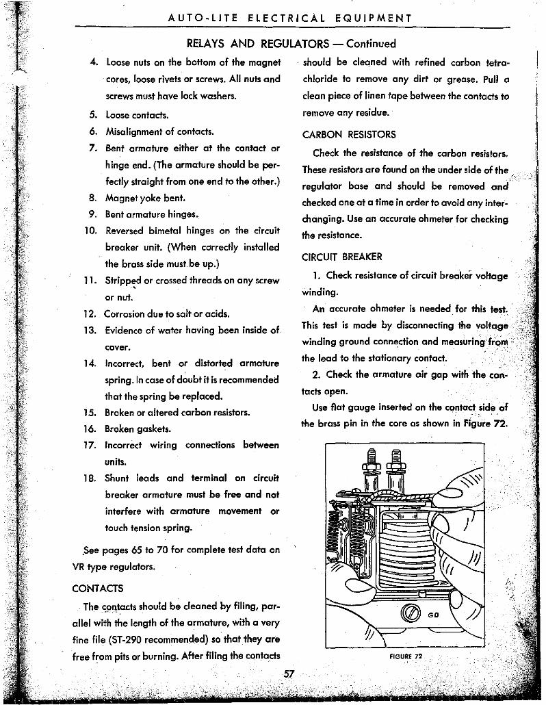
2. Check the armature air gap with the con
tacts open.
Use flat gauge inserted on the c()ntact side of
the brass pin in the core as shown in Figure 72.
FIGURE 72
AUTO-LITE ELECTRICAL EQUIPMENT
RELAYS AND REGULATORS - Continued
\\ \
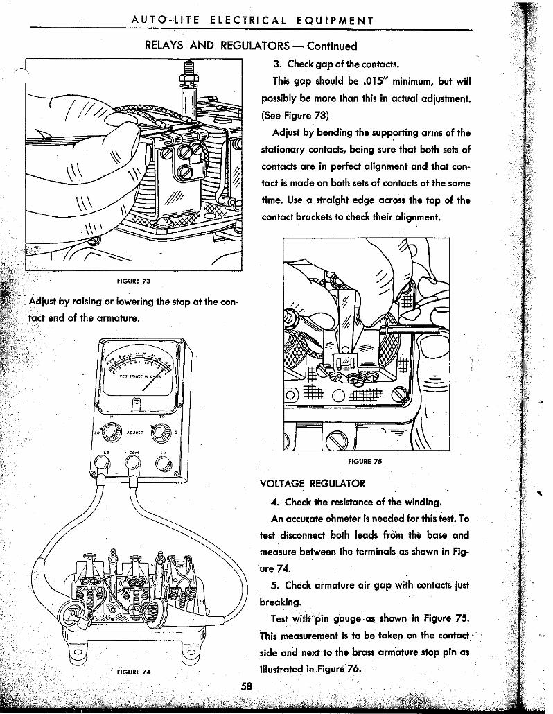
FIGURE 73
Adjust by raising or lowering the stop at the con
tact end of the armature.
"" a
FIGURE 74
58
3. Check gap of the contacts.
This gap should be .015" minimum, but will
possibly be more than this in actual adjustment.
(See Figure 73)
Adjust by bending the supporting arms of the
stationary contacts, being sure that both sets of
contacts are in perfect alignment and that con
tact is made on both sets of contacts at the same
time. Use a straight edge across the top of the
contact brackets to check their alignment.
FIGURE 7S
VOLTAGE REGULATOR
4. Check the resistance of the winding.
An accu~ate ohmeter is needed for this test. To
test disconnect both I.eads from the base and
measure between the terminals as shown in Fig
ure 74.
. 5. Check armature air gap with contacts just
breaking.
Test with 'pin gauge as shown in Figure 75.
This measurement is to be taken on the contact·
side and next to the brass armature stop pin as
illustrated in Figure 76.
AUTO-LITE ELECTRICAL EQUIPMENT
RELAYS AND REGULATORS - Continued
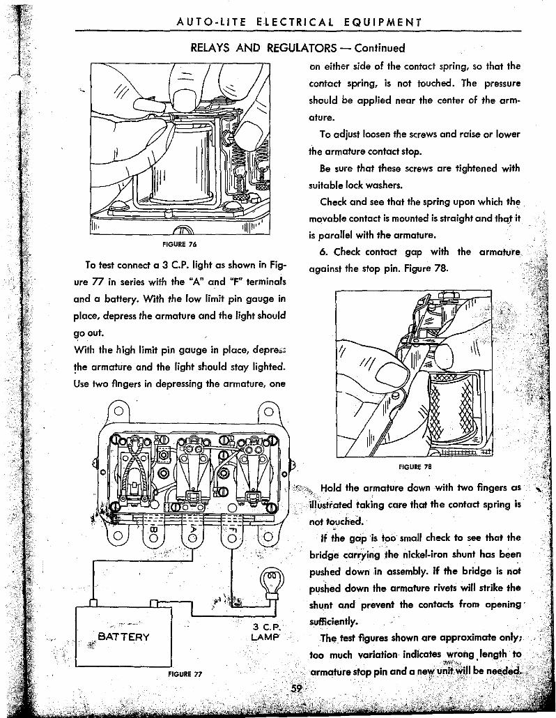
FIGURE 76
To test connect a 3 c.P. light as shown in Fig
ure 77 in series with the "A" and "F" terminals
and a battery. With the low limit pin gauge in
place, depress the armature and the light should
go out.
With the high limit pin gauge in place, depre.~
the armature and the light should stay lighted.
Use two fingers in depressing the armature, one
o
on either side of the contact spring, so that the
contact spring, is not touched. The pressure
should be applied near the center of the arm
ature.
To adjust loosen the screws and raise or lower
the armature contact stop.
Be sure that these screws are tightened with
suitable lock washers.
Check and see that the spring upon which the.
movable contact is mounted is straight and thot 'it
is parallel with the armature.
6. Check contact gap with the armature
against the stop pin. Figure 78.
FIGURE 78
, "~"'"~.. Hold the armature down with two fingers as
1;;;;lte\;;;LV jlh,strated taking care th.ot the contact spring is
~~~:rt§~-~-~-~-§~ .. ~=--~~~:~~~4 not touched •. :;;- ...,
--,,_.'-
BATTERY
o 0 If the gap 'istpo small check to see that the
FIGURE 77
3 C.P. LAMP
bridge car..yi~g 'he nickel-iron shu~t has been
pushed down .in assembly. If the bridge is not
pushed down the armature rivets will strike the
shunt and prevent the contacts from opening'
sufficiently.
The test figures shown are approximate only;
too much variation indicates wrang ,length to ~'~~:b<_
armafure stop pin and a ney(unitWW be ne,!'dl!d •. - ".' ~- -, - '
AUTO-LITE ELECTRICAL EQUIPMENT
RELAYS AND REGULATORS - Continued
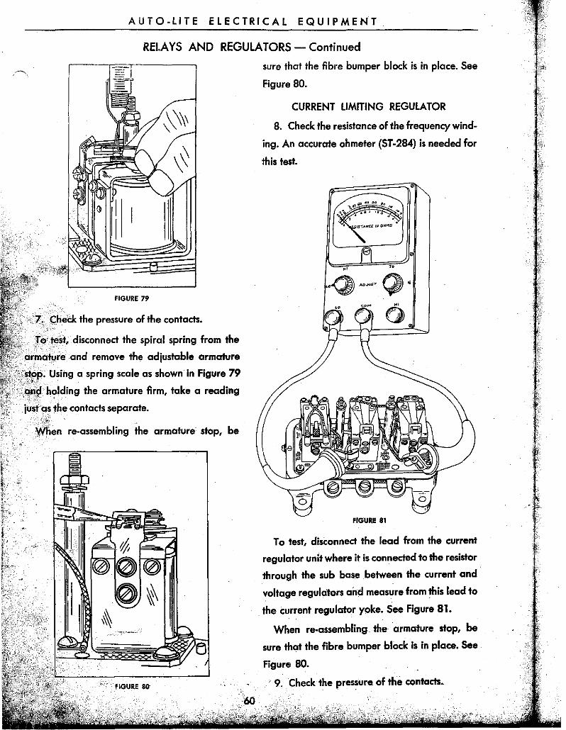
FIGURE 79
;Chei:k the pressure of the contads. " .
:r (;tesf, disconnect the spiral spring from the '~'", ..
i clrmlclfjm! and remove the adjustable armature
cy,;C~tpIP' Using a spring scale as shown in Figure 79
holding the armature firm, take a reading
~s the contacts separate. '. N,L' When re-assembling the armature stop, be
sure that the fibre bumper black is in place. See
Figure 80.
CURRENT LIMITING REGULATOR
8. Check the resistance of the frequency wind
ing. An accurate ohmeter (ST-284) is needed far
this test.
FIGURE 81
To test, disconnect the lead from the current
regulator unit where it is connected to the resistor
through the sub base .between the current and
voltage regulators and measure from this lead to
the current regulator yoke. See Figure 81.
When re-assembling the armature stop, be
sure that the fibre bumper block is in place. See
Figure 80.
, 9. Check the pressure of the contads.
AUTO-LITE ELECTRICAL EQUIPMENT
RELAYS AND REGULATORS - Continued
To test, disconnect the spii'al spring from the
armature and remove the adjustable armature
stop. Using a spring scale as shown in Figure 79
and holding the armature firm, take a reading
just as the contacts separate.
When re-assembling the armature stop be sure
that the fibre bumper I;>lock is in place. See Figure
80.
10. Check armature air gap with the contacts
just breaking.
Test with pin gauge. This is to be measured on
the contact side of the brass armature stop pin as
shown in Figure 76.
To test connect a 3C.P. light in series with the
"A" and "F" terminals and a battery as illustrated
in Figure 77. With the low limit pin gauge in
place depress the armature and the light should
go out. With the high limit pin gauge in place the
light should stay lighted. Use two fingers in de
pressing the armature, one on either side of the
contact spring, so that the contact spring is not
touched. The pressure should be applied near
the center of the armature.
To adjust loosen the screws and raise or lower
the armature stop.
Be sure these screws are tightened with suitable
lock washers.
The spring upon which the movable contact Is
mounted should be straight and parallel with
" ,the armature.
11. Check contact gap" with the armature ,:'
length to armature stop pin and a new unit will
be needed.
RE-ASSEMBLING THE REGULATOR
When all the preceding checks and adjust
ments have been completed, all the leads which
have been disconnected either by the removal of
a screw or by unsoldering should be reconnected.
Where resoldering is necessary, care must be
taken that a good clean contact is made. Do not
use acid for soldering flux.
After the regulator has been completely .. ;t assembled, its bottom should be struck. sharply
on the bench several times to be sure that an
parts are settled in place. When doing this be sure ~
that it is struck squarely on all four mountinglug..,'
Re-check all adjustments.
TESTING AND ADJUSTING '\ .. ,
NOTE:-THE COVER MUST BE ON THEREGU-i ~
LA TOR WHEN TAKING READINGS OR WI-lEN
THE UNIT IS BEING,HEATED BY OPIERA.T:{QII'I,
PRIOR TO TAKING READINGS. THIS IS
ESSARY DUE TO THE FACT THAT THE COVER
HELPS RETAIN THE HEAT.,
When testing or adjusting regulators, care"
must be taken that it is mounted firmly gnd in 'i" place where there is no vibration. It must also be· tested in the same position as it is mounted on the
car.
,Care must be taken in making the various tesf
connections that these connections are fjrtnl~ made so that the resistance of all
does not ~xceed .01 ohms with a
charge. It is for this rea~n that spring.
nections are no! recommended. Flexible cgbleis.
which have Rat spade type ter'mil,als nr,1> r ..... " ...
AUTO-LITE ELECTRICAL EQUIPMENT
RELAYS AND REGULATORS - Continued
mended, as experience shows that these prevent
high resistance connections from entering into
the test circuit.
It is suggested that a single earphone (2000
ohms or higher) be attached to the "F" terminal
and ground and used for listening to the regu
lator armature vibrations and so obtain an ac
curate indication of the operation of the current
limiting and voltage regulator units.
the regulator by operating it for 15 min
the ge~~rpfor charging 10 amperes.
\.vII.:I_ heating the regulator have the cover on the
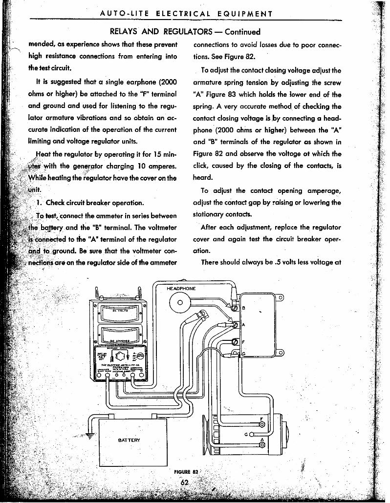
1. Check circuit breaker operation.
, • ' To test, connect the ammeter in series between < ,#" ,~
~E! ,ba'lteiY and the "B" terminal. The voltmeter
~;~()nllected to the "A" terminal of the regulatar
ground. Be sure that the voltmeter con
nectic)n! anion the regulator side of the ammeter
BATTERY
connections to avoid losses due to poor connec
tions. See Figure 82.
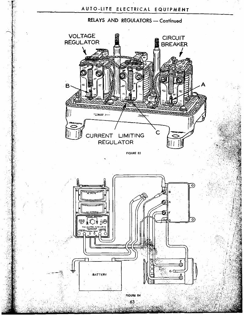
To adjust the contact closing voltage adjust the
armature spring tension by adjusting the screw
"An Figure 83 which holds the lower end of the
spring. A very accurate method of checking the
contact closing voltage is by connecting a head
phone (2000 ohms or higher) between the "A"
and "S" terminals of the regulator as shown in
Figure S2 and observe the voltage at which the
click, caused by the closing of the contacts, is
heard.
To adjust the contact opening amperag~,
adjust the contact gap by raising or lowering the
stationary contacts.
'After each adjustment, replace the regulator
cover and again test the circuit breaker oper
ation.
There should always be .5 volts less voltage at
AUTO-LITE ELECTRICAL EQUIPMENT
RELAYS AND REGULATORS - Continued
VOLTAGE REGULATOR
" B
CURRENT LIMITING REGULATOR
FIGURE 83
BATTERY
FIGURE 84
CIRCUIT BREAKER ,
A
~,
AUT 0 - LI TE E L E C T R I CAL EQ U I PM E NT
RELAYS AND REGULA TO~S - Continued
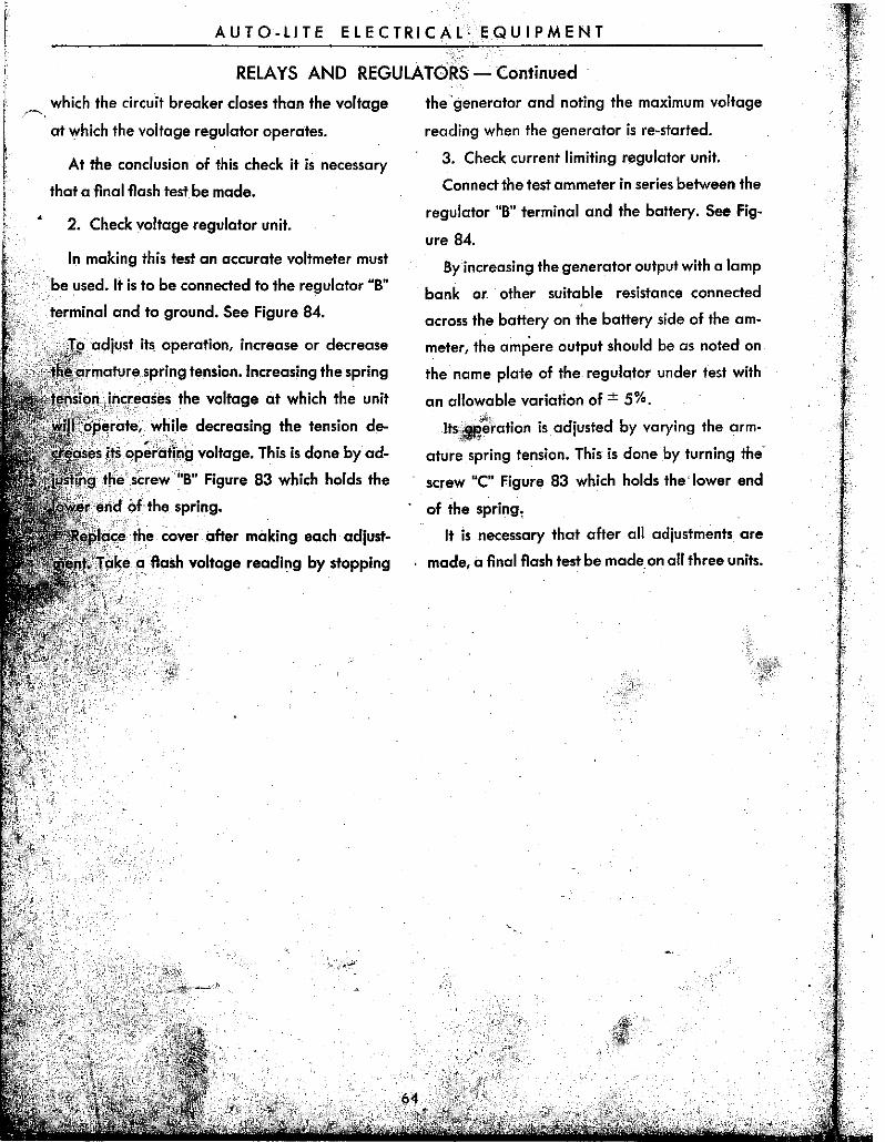
which the circuit breaker closes than the voltage
at which the voltage regulator operates.
At the conclusion of thIs check it Is necessary
that a flnal·flash test be made.
2. Check voltage regulator unit.
In making this test an accurate voltmeter must
be used. It is to be connected to the regulator "B"
terminal and to ground. See Figure 84.
adjust Its operatIon, increase or decrease
lTnlatlure sprIng tensIon. Increasing the spring
si()l~jl'c,[I,ases the voltage at which the unit
'Tolpe"at1e, while decreasing the tension de
!ts,lqpE!rol!ing voltage. This is done byad
,screw'uB" Figure 83 which holds the
••• the cover after making each adjust
a, flash voltage reading by stopping
the generator and noting the maximum voltage
reading when the generator is re-started.
3. Check current limiting regulator unit.
Connect the test ammeter in series between the
regulator "B" terminal and the battery. See Fig-
ure 84.
By increasing the generator output with a lamp
bank O~ other suitable resistance connected
across the battery on the battery side of the am
meter, the ampere output should be as noted on
the name plate of the regulator under test with
an allowable variation of ± 5%.
Its~~'ration is adjusted by varying the arm
ature spring tension. This is done by turning the'
screw "C" Figure 83 which holds the' lower end
of the spring,
It is necessary that after all adjustments are
made, a final flash test be made on all three units.
AUTO-LITE ELECTRICAL EQUIPMENT
RELAYS AND REGULATORS - Continued
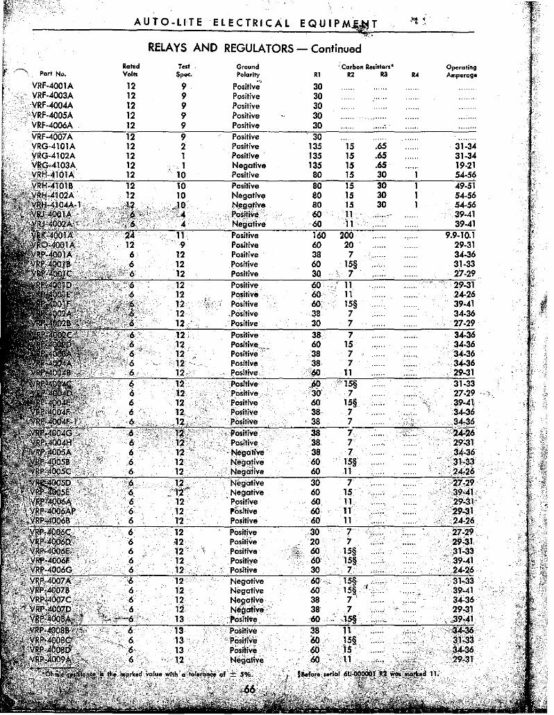
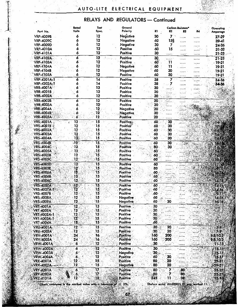
NUMERICAL LIST OF VR TYPE REGULATORS See page 68 for test specifications.
Rated Test Ground Carbon Resistors· Operating Part No. Volts Spec. . Polarity Rl R2 R3 R4 Amperage
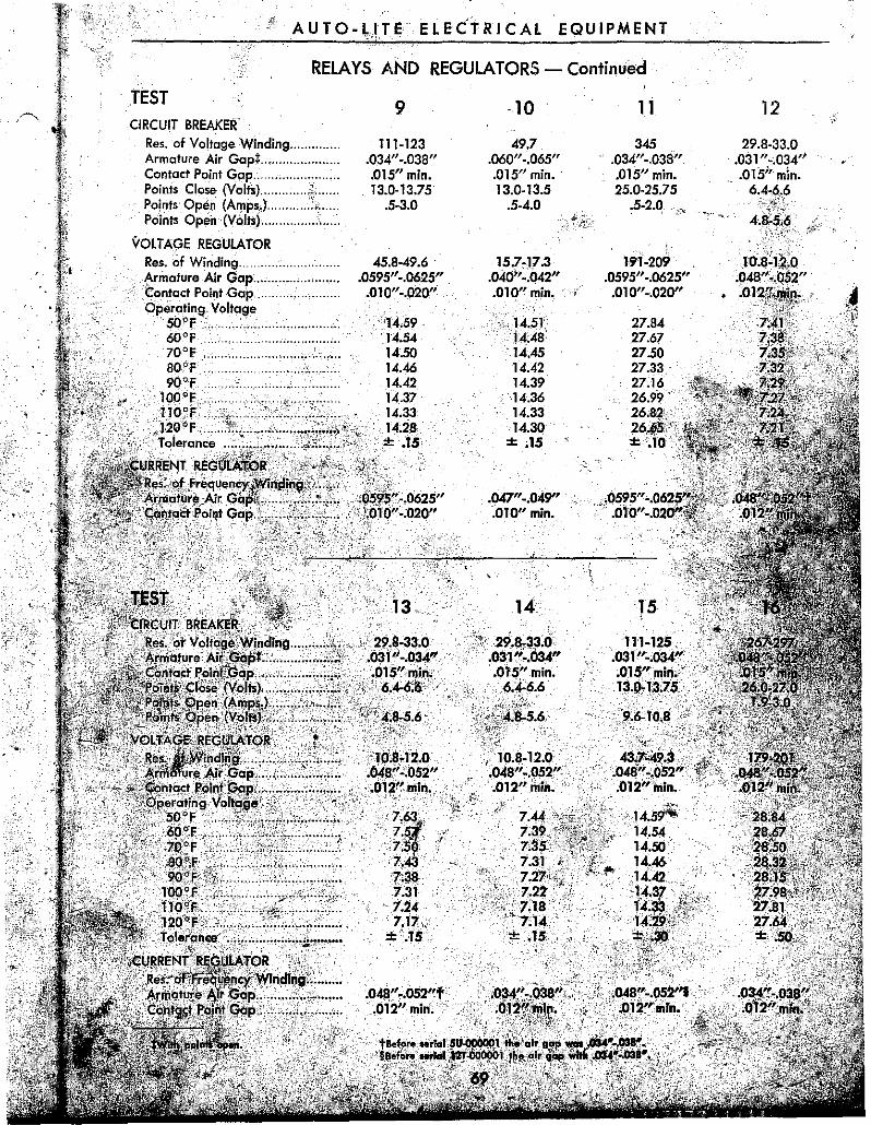
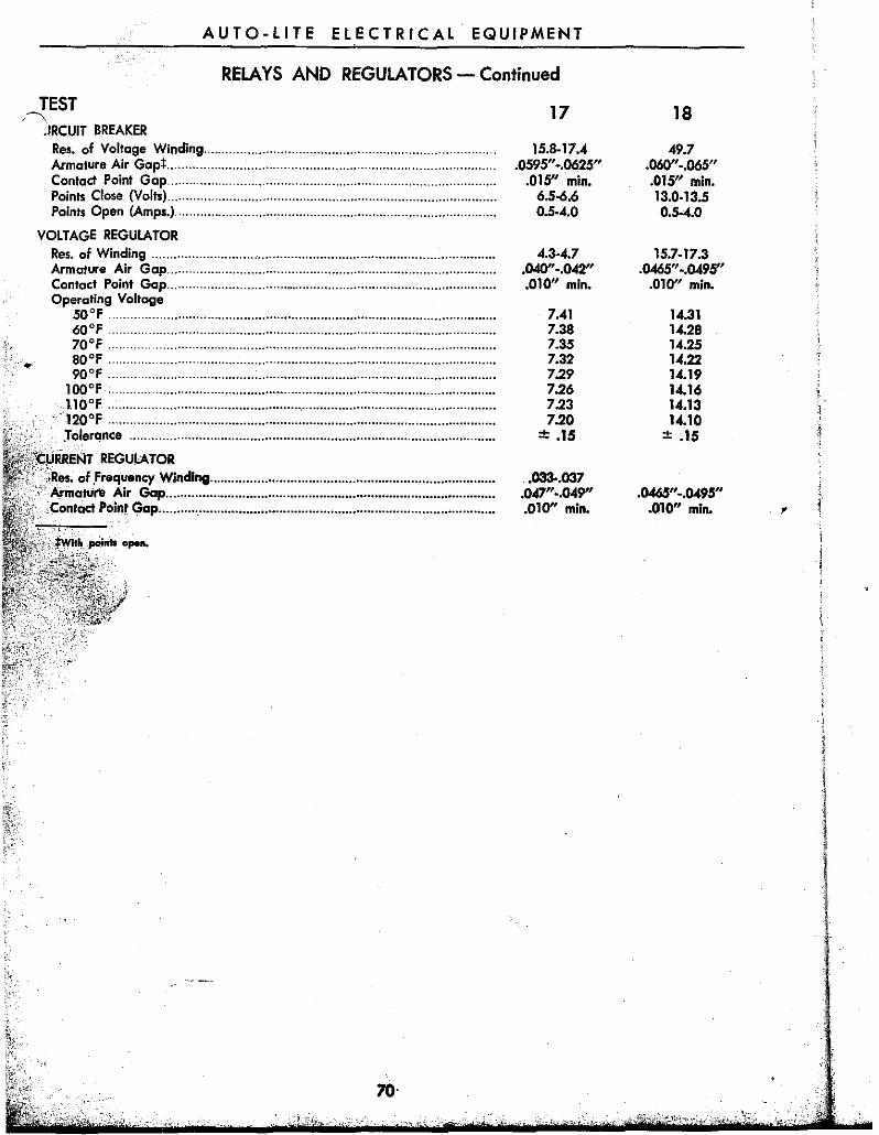
Res. of Voltage Winding ...... . Ar.mafure Air GapL ,Confact Point Gap ..................... .. Points Close (Volts) .. . Points Open (Amps.) ................. .
.IRCUIT BREAKER Res. of Voltage Winding ............................................................................ .. Armature Air Gapt ......................................................................................... . Contact Point Gap ........................................................................................ . Points Close (Volts) ........................................................................................ .. Points Open (Amps.) ...................................................................................... ..
VOLTAGE REGULATOR Res. of Winding ............................................................................................ .. Armature Air Gap ......................................................................................... . Contact Point Gap .......................................................................................... . Operating Voltage
;:,,+'KKt:NT REGULATOR of ,Frequency Winding ............................................................................. .
'Cc ,'rn,al'lII'8 Air Gap ......................................................................................... . Conlact Poinl Gap .......................................................................................... ..
70·
17
15.8-17.4 .0595"-.0625"
.015" min. 6.5-6.6 0.5·4.0
4.3-4.7 .040"-.042" .010" min.
7.41 7.38 7.35 7.32 7.29 7.26 7.23 7.20
± .15
.033-.037 .047"-.049" .010" min.
18
49.7 .060" ... 065" .015" min. 13.0·13.5 0.5--4.0
15.7-17.3 .0465"-.0495"
.010" min.
14.31 14.28 14.25 14.22 14.19 14.16 14.13 14.10
± .15
.0465"-.0495" .010" min. ,
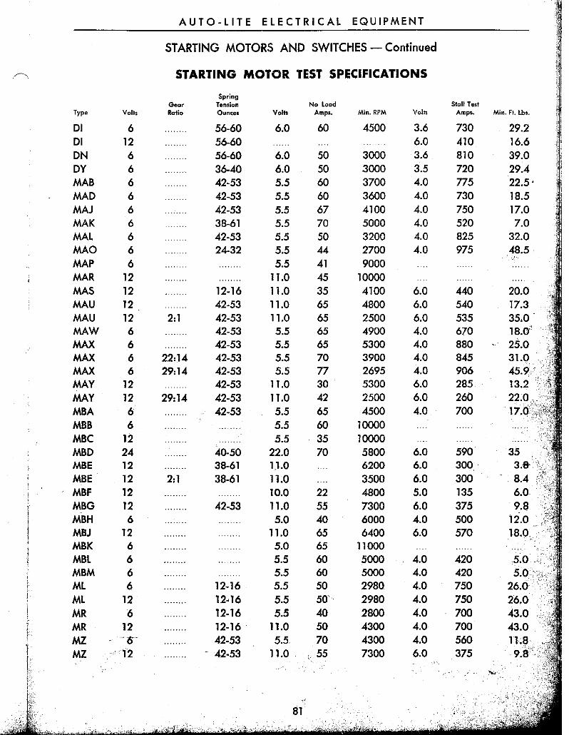
AUTO-LITE ELECTRICAL EQUIPMENT
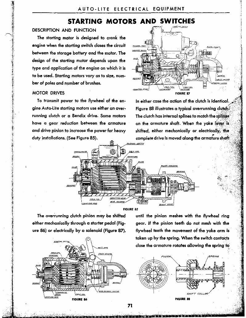
STARTING MOTORS AND SWITCHES DESCRIPTION AND FUNCTiON
The starting motor is designed to crank the
engine when the starting switch closes the circuit
between the storage battery and the motor. The
design of the starting motor depends upon the
type and application of the engine on which it is
to be used. Starting motors vary as to size, num
ber of poles and number of brushes.
MOTOR DRIVES
To transmit power to the flywheel of the en
gine Auto-lite starting motors use either an over
running clutch or a Bendix drive. Some motors
have a gear reduction between the armature
and drive pin ian to increase the power for heavy
duty ,installations. (See Figure 85).
FIGURE 87
In either case the action of the clutch is identical.
Figure 88 illustrates a typical overrunning d, ukoh,'
The clutch has internal splines to match the "
on the armature shaft. When the yoke '''''.", .•
shifted, either mechanicolly or eleicfr'icaIlY:' JI' -:', -':-,
complete drive is moved along the armature shalt;'
FIGURE 85
The over~unning clutch pinion may be shifted
either mechanically through a starter pedal (Fig
ure 86) or electrically by a solenoid (Figure 87).
FIGURE 86
71
until the pinion meshes with the flywheel ring
gear. If the pinion teeth do not mesh with the
flywheel teeth the movement of the yoke arm is
taken Up by the spring. When the switch contacts
close the armature rotates allOWing the spring to v
FIGIIIIE 88
AUTO-LITE ELECTRICAL EQUIPMENT
STARTING MOTORS AND SWITCHES - Continued
complete the meshing action and crank the en-,~
ne. As soon as the engine starts the flywheel
drives the pinion faster than the starting motor
armature bringing the clutch into action and pre
venting the engine from driving the armature at
excessive speeds.
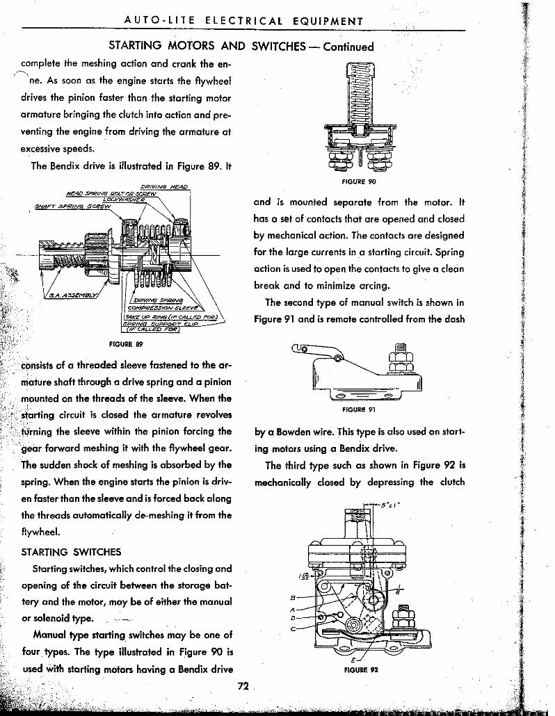
The Bendix drive is illustrated in Figure 89. It
FIGURE 89
consists of a threaded sleeve fastened to the ar
mature shaft through a drive spring and a pinion
mounted on the threads of the sleeve. When the
~iarting circuit is closed the armature revolves ,,' turning the sleeve within the pinion forcing the
gear forward meshing it with the flywheel gear.
The sudden shock of meshing is absorbed by the
spring. When the engine starts the pinion is driv
en faster than the sleeve and is forced bock along
the threads automatically de-meshing it from the
flywheel.
STARTING SWITCHES
Starting switches, which control the closing and
opening of the circuit between the storage bat
tery and the motor, may be of either the manual
or solenoid type.
Manual type starting switches may be one of
four. types. The type illustrated in Figure 90 is
used with starting motors having a Bendix drive
72
FIGURE 90
and is mounted separate from the motor. It
has a set of contacts that are opened and closed
by mechanical action. The contacts are designed
for the large currents in a starting circuit. Spring
action is used to open the contacts to give a clean
break and to minimize arcing.
The second type of manual switch is shown in
Figure 91 and is remote controlled from the dash
FIGURE 91
by a Bowden wire. This type is also used on start
ing motors using a Bendix drive.
The third type such as shown in Figure 92 is
mechanically closed by depressing the clutch
FIGURE 92
AUTO-LITE ElECTRICAL EQUIPMENT
STARTING MOTORS AND SWITCHES - Continued
pedal and has a vacuum release and vacuum re
lease lock to prevent operation of the starting
motor when the clutch pedal is depressed while
the engine is running. With the engine not run
ning depressing the clutch pedal closes the start
ig switch thru cam "A," latch "B" and pressure arm
"C." When the engine starts the latch "B" is lifted
thru a connection to the vacuum diaphragm
so that it disengages with the cam and the switch
is opened by spring action. As long as the engine
continues to run the latch is held in the disen
gaged position so that the clutch pedal can be
operated without closing the switch.
The last type such as shown mounted on the
motor illustrated in Figure 86 is used only on
motors with overrunning clutches. It is controlled
by a foot pedal that is connected by linkage to
the shift yoke which moves the clutch pinion into
mesh and then closes the switch contacts.
Solenoid starting switches may be divided into
two types: those which magnetically dose the
starting circuit and those which not only close the
starting circuit but also shift the overrunning
clutch pinion.
TO STARTER
\ TERt1,W"L pos 7
~P"UN,C;ER SPRING
--I'-1""Ne"TIC COIL.
FIGURE 93
The first of these types is shown in Figure 93
and is used with Bendix drive motors. It magnet
ically closes the circuit between the storage bat
tery and the motor and is controlled by a push
button located on the instrument panel.
The second type not only magnetically closes
the starting circuit but it also shifts the overrun"
ning clutch pinion into mesh with the flywheel
~7;:::r::;~,"","J."t:=--' GROU~ID TO SWITCH COVER
FIGURE 94
73
AUTO-LITE ELECTRICAL EQUIPMENT
STARTING MOTORS AND SWITCHES - Continued
gear. It is controlled by a push button, mounted ,~
<l" the instrument panel, thru a relay mounted
within the switch. (See Figure 94).
The solenoid coil includes two windings; a
series winding connected from the relay station
ary contact to the main switch terminal connect-, ing with the starter motor and a shunt winding
connected from the relay stationary contact to
ground. Between the time the relay contacts close
and the main switch is closed both windings have
current flowing thru them causing the solenoid to
exert its strongest magnetic pull on the plunger
thus assuring positive meshing of the pinion.
When the main switch contacts close the series
winding is short circuited and the plunger is held
in place by the shunt winding only. This results in
a minimum amount of arcing at the relay contacts
when the switch opens.
MAINTENANCE PROCEDURE
A periodic inspection should be made of the
starting circuit. While the interval between these
checks will vary accordng to the type of service
it should, under normal conditions, be made
every 5000 miles. At this check the following
points should be inspected.
1. Wiring
A visual inspection should be made of all wires
to be sure that none are broken and that all
connections are clean and tight.
2. Commutator
If the commutator is dirty or discolored it can
be cleaned with 00 sandpaper. Blow the sand
out of the motor after cleaning.
Should the commutator be ro'ugh or worn the
motor should be removed from the egine for
cleaning and reconditioning. Instructions for the
servicing of starting motors are given later in this
section.
3. Brushes
The brushes should slide or swing freely in
their holders and make-full contact on the com
mutator. Worn brushes should be replaced.
4. Lubrication
Motors having oilers should have 5 to 10 drops
74
of a good grade of S.A.E. No. 20 oil added each
5000 miles.
STARTING MOTOR OVERHAUL
At intervals of approximately 25,000 miles the
starting motor circuit should be thoroughly
checked and the motor removed from the car for
cleaning and checking.
1. Starting Circuit
The starting circuit should be inspected to be
sure all connections are clean and tight and that
the insulation on the wires is not worn or dam
aged. The starting circuit should be given a
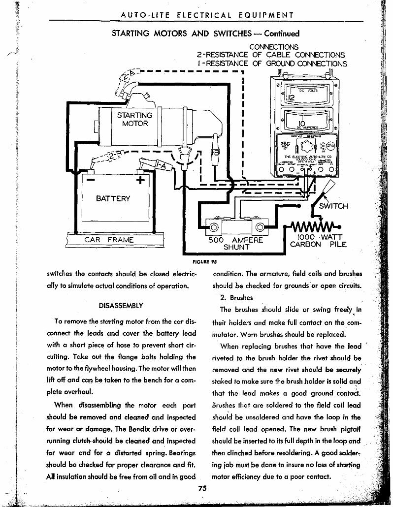
voltage loss test to make sure there is no loss of
starting motor efficiency due to high resistance
connections. (See Figure 95) In making this check
the voltage loss from the battery terminal to the
starting motor terminal should not exceed .12
volts maximum for each 100 amperes. The loss in
voltage between the battery ground post and the
starting motodrame should not exceed .12 volts
maximum for each 100 amperes. If the voltage
loss is greater than the above limits the voltage
should be measured over each part of the circuit
to locate the resistance causing voltage loss.
When measuring the voltage loss across solenoid
AUTO-LITE ELECTRICAL EQUIPMENT
STARTING MOTORS AND SWITCHES - Continued
CONNECTIONS 2-RESISTANCE OF CABLE C0NNECTIONS I - RESISTANCE OF GROUND CONNECTIONS ---------- -.,
STARTING MOTOR
,...I-,.,_'Q. ..... ~ - - - -, ... IC- ~
--\:--
- + BATTERY
P I I I
500 AMPERE SHUNT
1000 WATT CARBON PILE
FIGURE 9~
switches the contacts should be closed electric
ally to simulate actual conditions of operation.
DISASSEMBLY
To remove the starting motor from the car dis
connect the leads and cover the battery lead
with a short piece of hose to prevent short cir
cuiting. Take out the flange bolts holding the
motor to the flywheel housing. The motor will then
lift off and can be taken to the bench for a com
plete overhaul.
When disassembling the motor each part
should be removed a!ld cleaned and inspected
for wear or damage. The Bendix drive or over
running dutdHhould be cleaned and inspected
for wear and for a distorted spring. Bearings
should be checked for proper clearance and fit.
A" insulation should be free from oil and in good
75
condition. The ormature, field coils and brushes
should be checked for grounds ·or open circ':;its.
2. Brushes
The brushes should slide or swing freely, in
their holders and make full contact on the com
mutator. Worn brushes should be replaced.
When replacing brushes that have the lead
riveted to the brush holder the rivet should be
removed and the new rivet should be securely
staked to make sure the brush .holder is solid and
that the lead makes a good ground cantatt.
Brushes that are soldered to the field coil lead
should be unsoldered and have the loop in the
field coil lead opened. The new brush pigtail
should be inserted to its full depth in the loop and ..
then clinched before resoldering. A good solder"
ing job must be done to insure no loss of starting
motor efficiency due to a poor contact.
i , .
AUTO-LITE ELECTRICAL EQUIPMENT
STARTING MOTORS AND SWITCHES - Continued
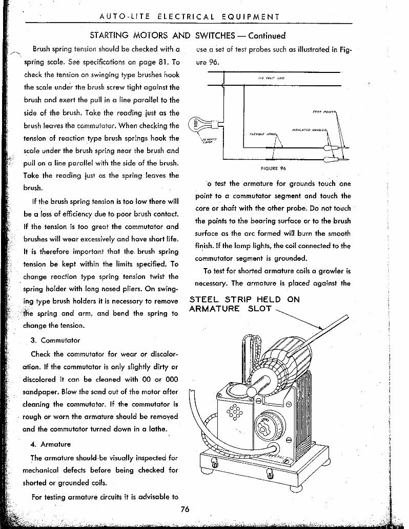
Brush spring tension should be checked with a
spring scale. See specifications on page 81. To
check the tension on swinging type brushes hook
the scale under the brush screw tight against the
brush and exert the pull in a line parallel to the
side of the brush. Take the reading just as the
brush leaves the commutator. When checking the
tension of reaction ,type brush springs hook the
scale under the brush spring near the brush and
pull on a line parallel with the side of the brush.
Take the reading just as the spring leaves the
brush.
If the brush spring tension is too low there will
be a loss of efficiency due to poor brush contact.
If the tension is too great the commutator and
brushes will wear excessively and have short life.
It is therefore important that the. brush spring
tension be kept within the limits specified. To
change reaction type spring tension twist the
spring holder with long nosed pliers. On swing
ing type brush holders it is necessary to remove
'me spring and arm, and bend the spring to
change the tension.
3. Commutator
Check the commutator for wear or discolor
ation. If the commutator is only slightly dirty or
discolored it can be cleaned with 00 ar 000
sandpaper. Blow the sand out of the motor after
cleaning the commutator. If the commutator is
rough or worn the armature should be removed
and the commutator turned down in a lathe.
4. Armature
The armature shovld·be visually inspected for
mechanical defects before being checked for
shorted or grounded coils.
For testing armature circuits it is advisable to
76
use a set of test probes such as illustrated in Fig
ure 96.
T~ST POINTS
FIGURE 96
'0 test the armature for grounds touch one
point to a commutator segment and touch the
core or shaft with the other probe. Do not touch
the points to the bearing surface or to the brush
surface as the arc formed will b"rn the smooth
fi~ish. If the lamp lights, the coil connected to the
commutator segment is grounded.
To test for shorted armature coils a growler is
necessary. The armature is placed against the
STEEL STRIP HELD ON ARMATURE SLOT
AUTO-LITE ELECTRICAL EQUIPMENT
STARTING MOTORS AND SWITCHES - Continued
core and a steel strip held on the armature. The
armature is then rotated slowly by hand. If a
shorted coil is present the steel strip will become
magnetized and vibrate. This test is illustrated in
Figure 97.
5. Field Coils
Using the test probes illustrated in Figure 96
check the field coils for both opens and grounds.
To test for grounds place one probe on the motor
frame or pole piece and touch the other probe to
the field coil terminals. If a ground is present the
lamp will light.
Ta test for open circuits place the probes on
the field coil terminals across each coil separate
ly. If the light does not light the coil is open
circuited.
6. Brush Holder Inspection
Using the test probes illustrated in Figure 96
touch the insulated brush holder with one probe
and a convenient ground on the C.E. plate with
the other probe. If the lamp lights it indicates a
grounded brush holder.
7. Assembly of Motor
When assembling absorbent bronze bearings
always use the proper arbor as these arbors are
designed to give the proper bearing fit. Soak
the bearing in oil before assembling in the bear
ing bore.
The pinion end of the armature shaft should be
given a light wipe with very light oil when
assembling.
Brushes should be correctly installed and con
nected as previously outlined in order to be sure
of proper~,sf<'rting motor efficiency. Proper brush
seating should be insured by sanding the brushes
to fit the commutator. To sand the brushes wrap
a strip of 00 sandpaper around the commutator
77
and turn the armature slowly in the direction of
rotation. Blow the sand and carbon dust out of
the motor after sanding.
When installing the yoke and overrunning
clutch the yoke shoes should be assembled with
the radial side toward the pinion end of the
clutch.
8. lubrication
Auto-Lite starting motors are equipped with
absorbent bronze bearings. These bearings are
able to absorb 25% of their own volume in oil.
Most of the drive end and intermediate bear
ings do not need any attention. The commutato~
end bearing and some of the intermediate bear
ings are equipped with oilers which should be
given 5 to 10 drops of medium engine oil every
5000 miles. Do not over lubricate as excessive
lubrication will damage commutators and insu
lation.
Gear reduction motors have a grease pocket
in the gear chamber which should be filled with
a high melting point grease when assembling. If
this gear reduction is provided with a grease cup
it should be given one turn every 5000 miles. If an
oiler is provided it should be given 5 to 10 drops
of medium engine oil every 5000 miles.
When the starting motor is serviced the bear
ings should be soaked in oil and the bearing seats
should be given a light wipe of oil.
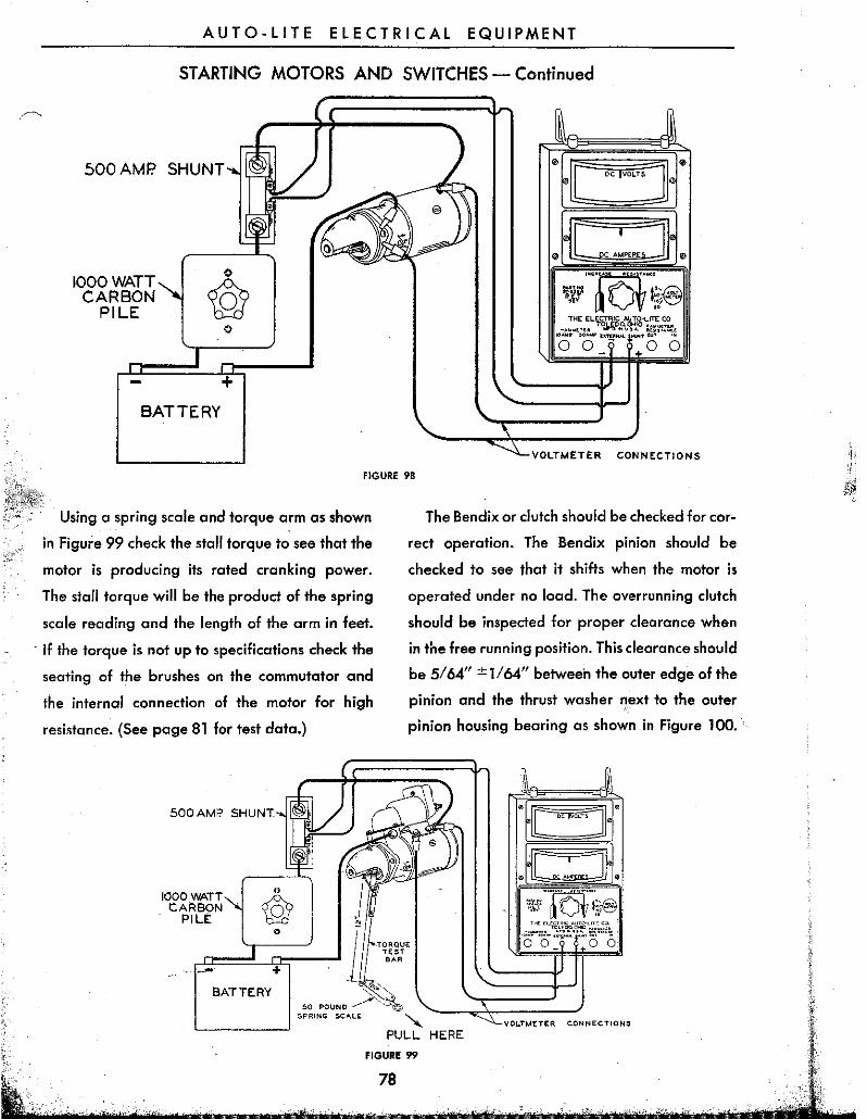
9. Bench Test
Tlie motor should first be checked to see that
the free running voltage and current are within
specifications. (See page 81 for test data.) To test
connect the motor to a battery and voltmeter
as in Figure 9B. If the current is too high check
the bearing alignment and end play to make
sure there is no binding or interference.
AUTO-LITE ELECTRICAL EQUIPMENT
STARTING MOTORS AND SWITCHES - Continued
500 AMP. SHUNT
1000 WATT CARBON
PILE o
BATTERY
[
"'--vc,Ln .. TER CONNECTIONS
FIGURE 98
Using a spring scale and torque arm as shown
in Figure 99 check the stall torque to see that the
motor is producing its rated cranking power.
The stall torque will be the product of the spring
scale reading and the length of the arm in feet.
. If the torque is not up to specifications check the
seating of the brushes on the commutator and
the internal connection of the motor for high
resistance. (See page 81 for test data.)
500 AMP. SHUNT
1000 WATT CA~80N
PILt
The Bendix or clutch should be checked for cor
rect operation. The Bendix pinion should be
checked to see that it shifts when the motor is
operated under no load. The overrunning clutch
should be inspected for proper clearance when
in the free running position. This clearance should
be 5164" ± 1164" between the outer edge of the
pinion and the thrust washer next to the outer
pinion housing bearing as shown in Figure 100.
TORQUE TEST ."
~~ 50 POUNO ~
8ATTERY
SPRING SCALE X L-______ ~J PULL HERE
VOLTMETER CONNECTIONS
FIGURE 99
78
AUTO-LITE ELECTRICAL EQUIPMENT
STARTING MOTORS AND SWITCHES - Continued
To check this clearance shift the pinion by apply
ing pressure to the yoke arm on the positive shift
type or by applying pressure to the plunger of the
solenoid switch on the magnetic gear shift type.
i PI.'IIO/V HOUSINt:i
FIGURE 100
To adjust the clearance, screw the starting switch
plunger in or out on the positive shift starting
motors or adjust the plunger screw on the mag
netic shift starting motors.
STARTING SWITCH TESTS
MANUAL. SWITCHES
This type of switch can best be tested by com
paring voltage readings between the terminal
connected to the battery and the terminal
connected to the starting motor. A maximum vari
ation not in excess of .05 volts per 100 amperes
is allowed. A greater variation indicates poor
switch contacts. Switch contacts should be filed
for full surface contact or the complete switch
replaced.
55-4000 SERIES SWITCHES
This type switch should be checked to see that
the opening and closing voltages are within limits
and that the voltage loss across the main contacts
is not in excess of .05 volts per 100 amperes.
When checking this voltage loss have the con-
79
tacts closed by ehergizing the switch to approxi
mate the actual conditions of operation.
TEST SPECIFICATIONS
Amperes Draw
6 volt units--2.9 to 3.3 amperes at 6 volts.
12 volt units--1.47 to 1.57 amperes at 12 volts.
Switch Contacts Close
6 volt units-4 to 5 volts
12 volt units-8 volts maximum
Switch Contacts Open
6 volt units-.5 to 2.0 volts
12 volt units-1.5 to 4.0 volts
55-4100, 55-4200 and 55-4700 SWITCHES
The relay contacts when open should have .025
inch minimum to .035 inch maximum gap.
Before making any tests on the switch make'
sure that cilliinkage operates freely with no bind
ing and that the switch plunger can be bottomed'
in the solenoid without drag or restriction. When
under test the plunger should bottom' instantly
without chattering.
TEST SPECIFICATIONS
55-4100-6 volt units
Relay
Contacts close 3.5 to 4.5 volts
Contacts open 1.5 to 2.5 volts
Solenoid
Shunt coil only 14 to 16 amperes at 6.0 volts
Shunt and series 34 to 38 amperes at 3.0 volts
55-4100-12 volt units
Relay
Contacts close 7.0 to 9.0 volts
Contact. open 3.0 to 5.0 volts
Solenoid
Shunt coil only 5.0 to 6.0 amperes at 12.0 volts
Shunt and series 22:0 to 26.0 amperes at 6.0 volts
AUTO-LITE ELECTRICAL EQUIPMENT
STARTING MOTORS AND SWITCHES - Continued
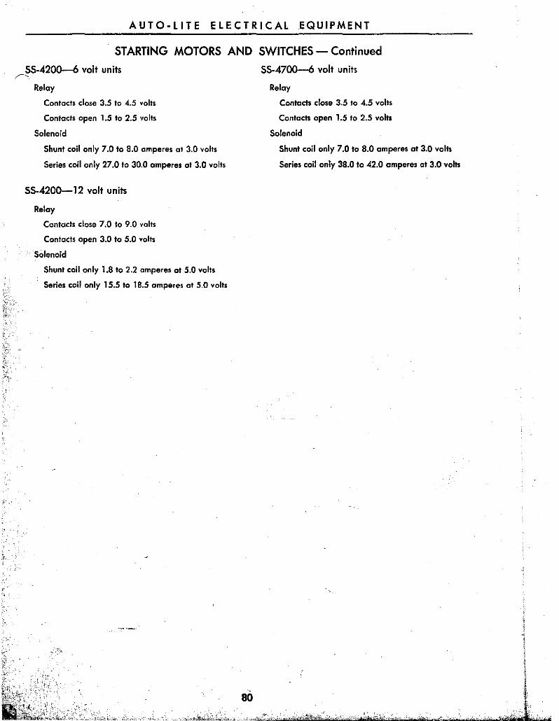
55-4200-6 volt units ~
Relay
Contacts close 3.5 to 4.5 volts
Contacts open 1.5 to 2.5 volts
Solenoid
Shunt coil only 7.0 to 8.0 amperes at 3.0 volts
Series coil only 27.0 to 30.0 amperes at 3.0 volts
55-4200--12 volt units
Relay
Contacts close 7.0 to 9.0 volts
Contacts open 3.0 to 5.0 volts
Solenoid
Shunt coil only 1.8 to 2.2 amperes at 5.0 volts
Series coil only 15.5 to 18.5 amperes at 5.0 volts
"'-,;.,.,
80
55-4700-6 volt units
Relay
Contacts close 3.5 to 4.5 volts
Contacts open 1.5 to 2.5 volts
Solenoid
Shunt coil only 7.0 to 8.0 amperes at 3.0 volts
Series coil only 38.0 to 42.0 amperes at 3.0 volts