Automating Staged Product Derivation for Heterogeneous Multi–Product-Lines — Automation der stufenweisen Produktableitung aus heterogenen Multi-Produktlinien Der Technischen Fakultät der Friedrich-Alexander-Universität Erlangen-Nürnberg zur Erlangung des Grades D OKTOR -I NGENIEUR vorgelegt von Christoph Elsner Erlangen — 2012
Automation der stufenweisen Produktableitungaus heterogenen Multi-Produktlinien
Der Technischen Fakultät derFriedrich-Alexander-Universität Erlangen-Nürnberg
zur Erlangung des Grades
DOKTOR-INGENIEUR
vorgelegt von
Christoph Elsner
Erlangen — 2012
Als Dissertation genehmigt vonder Technischen Fakultät
Friedrich-Alexander-Universität Erlangen-Nürnberg
Tag der Einreichung: 15. November 2011Tag der Promotion: 26. April 2012
Dekan: Prof. Dr.-Ing. habil. Marion MerkleinBerichterstatter: Prof. Dr.-Ing. habil. Wolfgang Schröder-Preikschat
A. Univ.-Prof. Dr. Paul Grünbacher
Abstract
Software constitutes a major cost factor when developing technical systems. To reducethis cost, systematic reuse of assets is necessary from early on when developing similarproducts—an approach that has become known as software product line engineering. Theautomation of product derivation, that is, the automated product creation from core assets,is one of the success factors of product line engineering. It has two facets: automatedsupport during configuration of a product, such as configuration consistency checks andautomated fixes, and automation of the actual generation of the product, via generativetechnologies, which produce product artifacts from the configuration.
Three critical factors, however, currently hamper the use of automated derivation tech-niques in industry: the heterogeneity of product derivation mechanisms, the stages in thederivation process, and the composition of several product lines to multi–product-lines.From feature modeling to C-preprocessor–based configuration, from the first decisiontaken during the initial customer contact stage to the last option set in a configurationfile at the system startup stage—each of possibly multiple involved product lines bringsdistinct product configuration and generation facilities to be used by different stakeholdersat dedicated stages in the derivation process.
Up to now, there are hardly any solutions neither for heterogeneity, nor for stages, nor formulti–product-lines—product derivation in industry results in an immense manual effort.No technical support is provided for configuration checking across heterogeneous configu-ration mechanisms, product lines, or configuration stages. Configuration inconsistenciesremain unnoticed and produce high cost due to prolonged testing and reconfigurationcycles and, ultimately, due to the delivery of defective products to customers.
This thesis contributes the PLiC approach, which automates staged product derivationfor heterogeneous multi–product-lines. Multi–product-lines are split up into productline components (PLiCs), which base upon three principles: extraction, declaration, andrestriction. The legacy configuration data of each PLiC is automatically and transparentlyextracted into models. The product line engineer declares further information on stagesand multi–product-lines in additional, concise models. This facilitates defining model-based constraint checks and fixes that ensure consistent product configuration and productgeneration over the whole staged derivation process of heterogeneous multi–product-lines.
The validation results show that the approach is comprehensively applicable to legacyproduct lines in a light-weight, little-invasive, and scalable manner. In doing so, thisthesis opens the way for bringing automated product derivation from research and insularproductive use to broad applicability in industrial practice.
iii
Zusammenfassung
Bei der Entwicklung technischer Systeme stellt Software einen bedeutenden Kostenfaktordar. Sind gleich mehrere, ähnliche Produkte zu entwickeln, hilft der Softwareproduktlinien-Ansatz durch frühe und systematisch geplante Wiederverwendung von Softwareanteilendie Kosten zu reduzieren. Insbesondere die automatische Produktableitung kann hierzubedeutend beitragen, indem sie Konfigurationsbeschreibungen automatisch auf produkt-spezifische Sofwareanteile abbildet. Die Automation bezieht sich hierbei einerseits aufdie Produktkonfiguration, welche durch automatische Überprüfung und Reparatur derKonfiguration deren Konsistenz sicherstellt, als auch auf die eigentlich Produktgenerierung,welche die Konfiguration auf Produktartefakte abbildet.
Bisher behindern jedoch drei Faktoren die industrielle Anwendung automatischer Pro-duktableitungstechniken: die Heterogenität der Produktableitungsmechanismen, mehrereStufen innerhalb der Produktableitung und die Komposition von mehreren Produktli-nien zu Multiproduktlinien. Von Merkmalmodellen bis zur Konfiguration über den CPräprozessor, von der ersten Entscheidung des Vertriebs beim Kunden bis zur letztenKonfigurationsoption vor dem Systemstart – jede der beteiligten Produktlinien bringt ihreeigenen Produktkonfigurations- und Produktgenerierungsmechanismen mit, welche vonBenutzern unterschiedlichster Rollen während der verschieden Produktableitungsstufenverwendet werden.
Für die heterogene und gestufte Produktableitung von Multiproduktlinien gibt es bisherkaum automatisierte Ansätze, so dass die Ableitung von Produkten in der Industrie weit-erhin mit einem immensen manuellen Aufwand verbunden ist. Es gibt keine technischeUnterstützung für die Konfigurationsüberprüfung über die Grenzen von Konfigurations-mechanismen, Produktlinien oder Ableitungsstufen hinaus. Konfigurationsinkonsistenzenbleiben daher unerkannt und erzeugen hohe Kosten durch erhöhten Test- und Rekonfigu-rationsaufwand – und führen schlimmstenfalls zur Auslieferung defekter Produkte an denKunden.
Der PLiC-Ansatz automatisiert die Produktableitung von gestuften und heterogenen Multi-produktlinien. Zunächst werden diese in Produktlinienkomponenten (product line compo-nents, PLiCs) zergliedert, welche auf drei Prinzipien basieren: Extraktion, Deklaration undRestriktion. Jegliche Konfigurationsdaten werden zunächst automatisch und transparentin ein einheitliches Modellformat überführt. Der Produktlinienentwickler deklariert zusät-zliche Informationen bezüglich der Produktableitungsstufen und der Multiproduktlinien-Struktur in weiteren Modellen. Dies ermöglicht die einheitliche Definition von Konfigura-tionseinschränkungen und Reparaturanweisungen auf Modellebene, womit die konsistente
v
Produktkonfiguration und -generierung über den gesamten gestuften und heterogenenProduktableitungsprozess von Multiproduktlinien sichergestellt wird.
Die Validierung zeigt die umfassende Anwendbarkeit des Ansatzes auf bereits existierendeProduktlinien auf, wobei er sich weiterhin als leichtgewichtig, gering-invasiv und tech-nisch skalierbar erweist. Dadurch bereitet diese Arbeit den Weg, die automatische Produk-tableitung von der Forschung und von vereinzeltem produktiven Einsatz in eine breiteAnwendung in der industriellen Praxis zu überführen.
vi
Acknowledgements
Many people have supported me in the course of writing this thesis. First of all, I wouldlike to express my deepest gratitude to my parents, who have always encouraged andsupported me from the very beginning of my life. Without their constant backup, thisthesis would have never been possible.
I am grateful to my thesis supervisor, Prof. Dr. Wolfgang Schröder-Preikschat, for givingme the opportunity to write my thesis in his group. The fruitful discussions and thepleasant working atmosphere in his group have provided me with a highly productiveenvironment for pursuing my PhD. Furthermore, I want to I thank my co-supervisor, Prof.Dr. Paul Grünbacher. The gainful and pleasant joint work in several projects and hisvaluable comments and suggestions on my research have improved this thesis a lot.
A very special thanks goes to Christa Schwanninger, who supervised my thesis on the partof the cooperation partner Siemens AG. Despite her tight schedule, she has provided mewith scientific background and industrial insights that are deeply reflected in the contentand contribution of this thesis.
I owe many thanks to Dr. Daniel Lohmann, who accompanied my research work fromits very beginnings. In many critical discussions, he has shaped my way of approachingproblems, finding solutions, and putting them on paper.
Last but not least, I want to thank all members of the System Software Group of theFriedrich-Alexander University of Erlangen-Nuremberg, as well as all my family andfriends for their ongoing support far beyond this thesis.
3.2 State of the Art in Heterogeneity and Its Deficiencies . . . . . . . . . . . . 423.2.1 Previous Strategies to Address Configuration Heterogeneity . . . . 423.2.2 Deficiencies of Previous Approaches Regarding Heterogeneity . . . 43
3.3 State of the Art in Staged Derivation and Its Deficiencies . . . . . . . . . . 45
ix
Contents
3.3.1 Previous Approaches to Address the Staged Derivation Process . . . 453.3.2 Deficiencies of Previous Approaches Regarding Staged Derivation . 48
B Appendix: Instructions for User Study Participants 149
Bibliography 153
xii
List of Figures
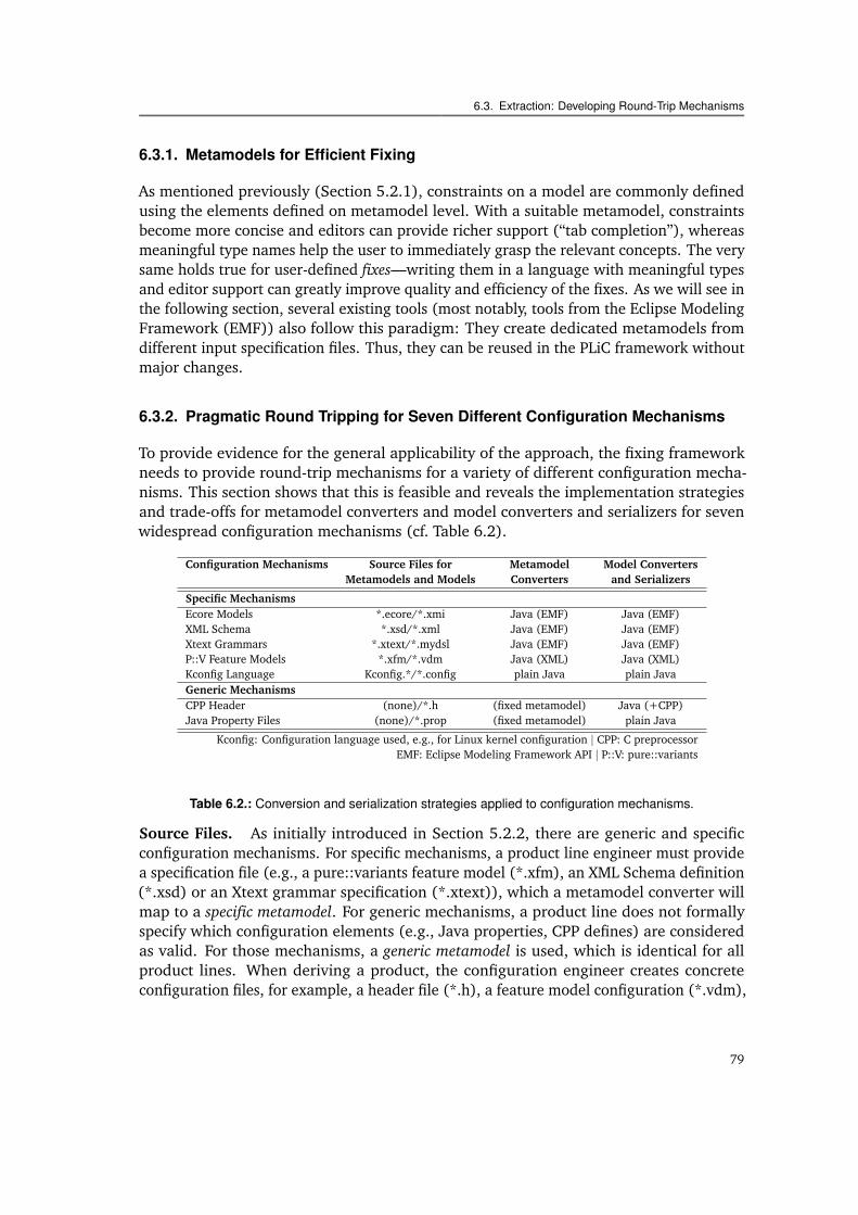
1.1 Product derivation from a magnetic resonance tomography product line. . 21.2 A hierarchical product line of medical imaging devices. . . . . . . . . . . . 4
2.1 Different types of multi–product-lines. . . . . . . . . . . . . . . . . . . . . 142.2 The essential ingredients of product derivation automation. . . . . . . . . 202.3 The heterogeneity of configuration mechanisms of the I4Copter. . . . . . . 212.4 The heterogeneity of configuration mechanisms of SafeHome. . . . . . . . 282.5 An overview of the staged derivation process of SmartHome. . . . . . . . . 31
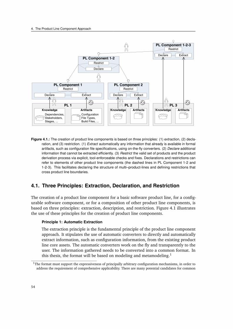
4.1 The three principles of the PLiC approach. . . . . . . . . . . . . . . . . . . 54
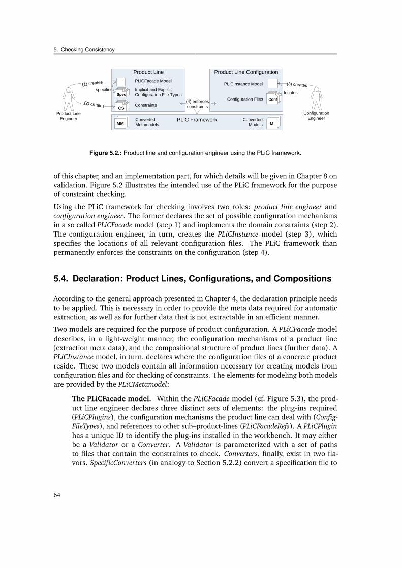
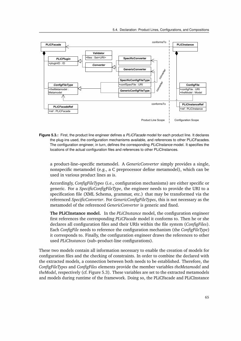
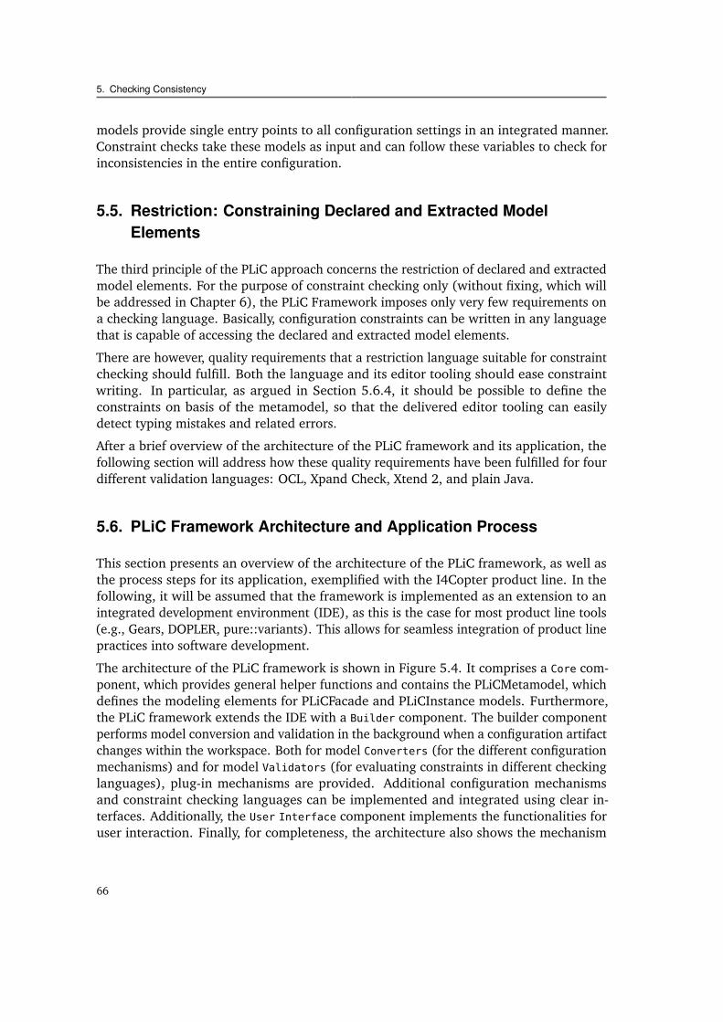
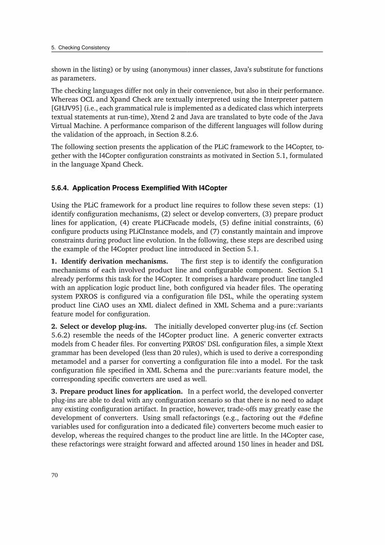
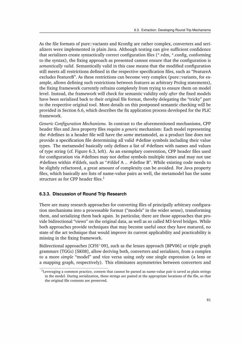
5.1 Exemplary domain constraints within the I4Copter product line. . . . . . . 605.2 Product line and configuration engineer using the PLiC framework. . . . . 645.3 The PLiCFacade and PLiCInstance models for product line modeling. . . . 655.4 The architecture of the PLiC framework. . . . . . . . . . . . . . . . . . . . 675.5 The constraints of the acceleration sensor in Xpand Check. . . . . . . . . . 715.6 Dedicated view of the IDE for displaying the inconsistencies. . . . . . . . . 72
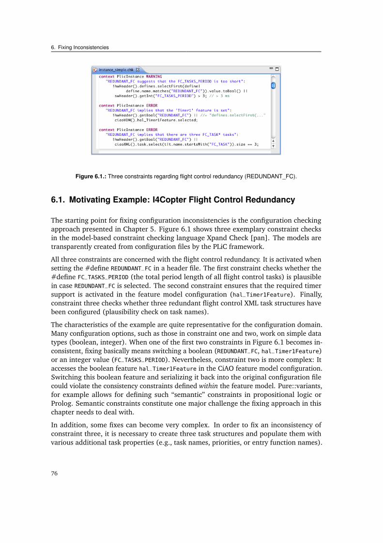
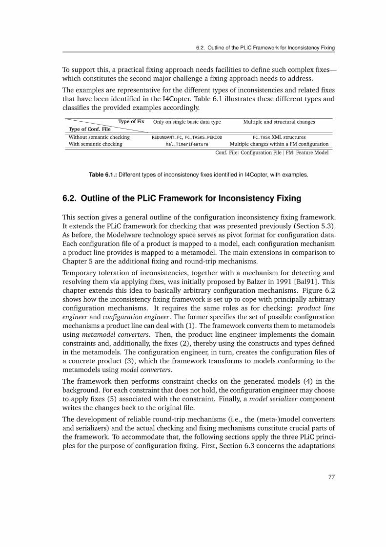
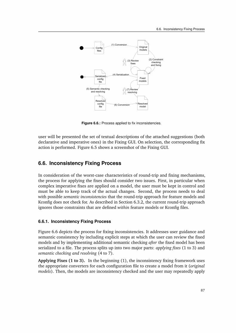
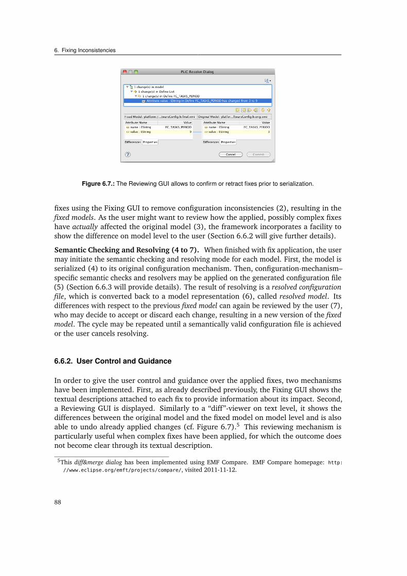
6.1 Three constraints regarding flight control redundancy (REDUNDANT_FC). 766.2 Product line and configuration engineer using the fixing framework. . . . 786.3 Mapping configuration mechanisms and files to metamodels and models. . 806.4 The flight control redundancy constraints with suggestion fixes. . . . . . . 866.5 The Fixing GUI generated for the suggestions A1 and A2 in Figure 6.4. . . 866.6 Process applied to fix inconsistencies. . . . . . . . . . . . . . . . . . . . . . 876.7 The Reviewing GUI allows to confirm or retract fixes prior to serialization. 88
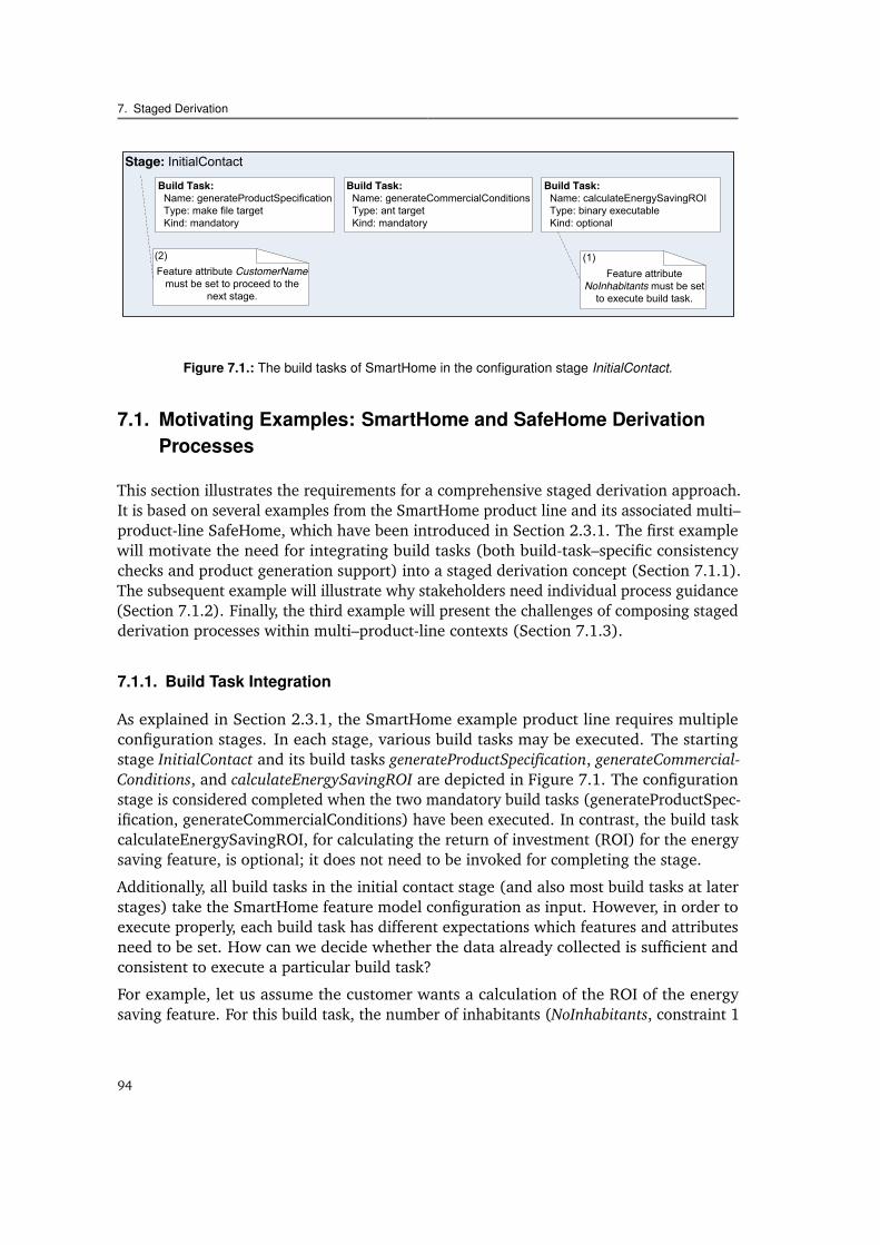
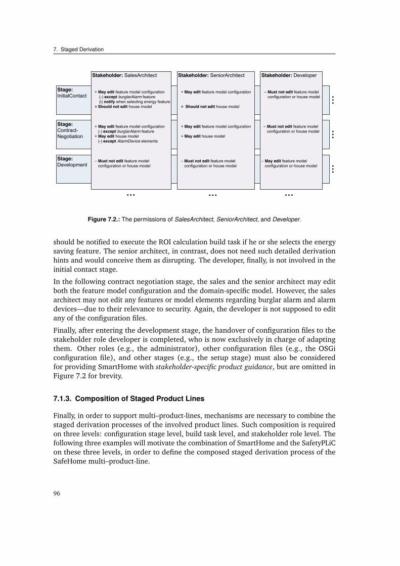
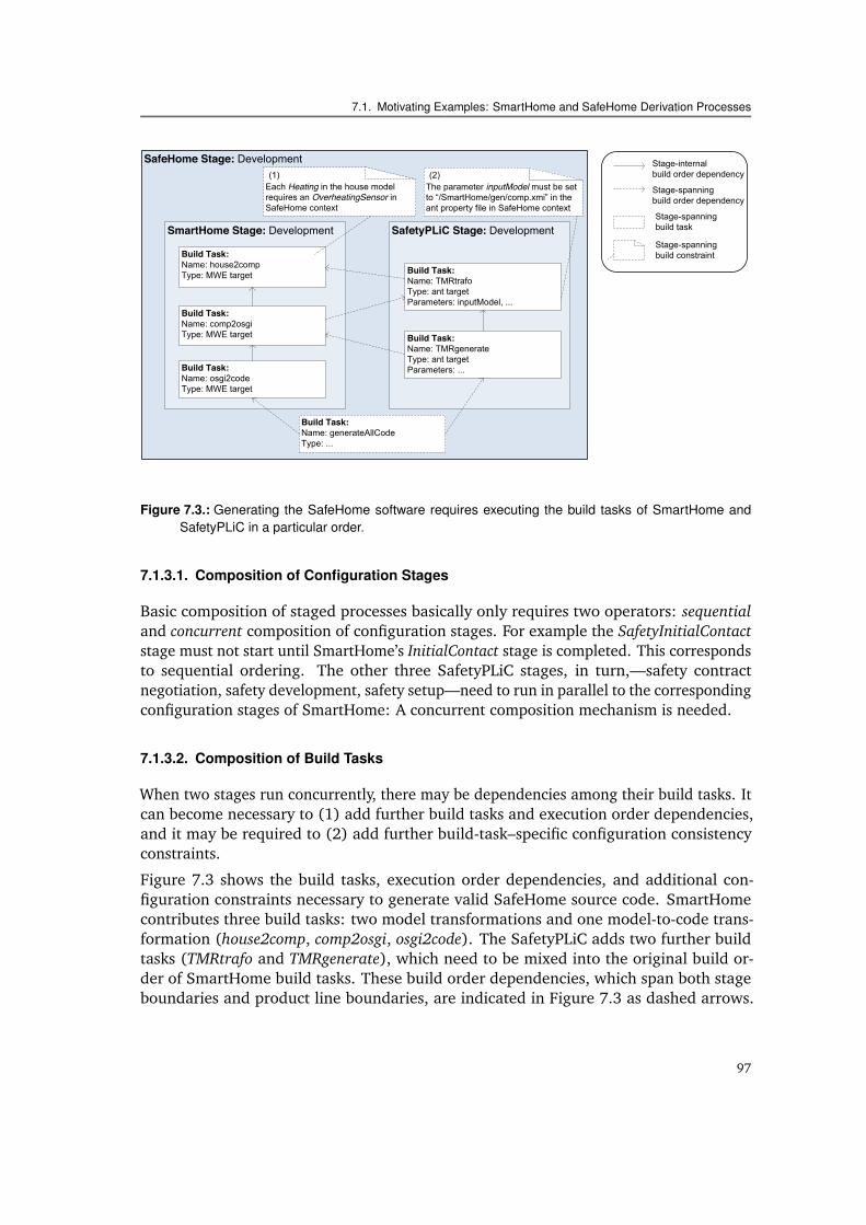
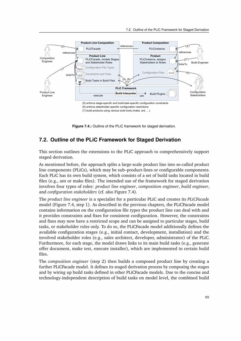
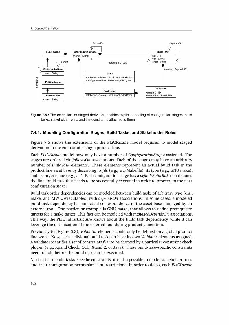
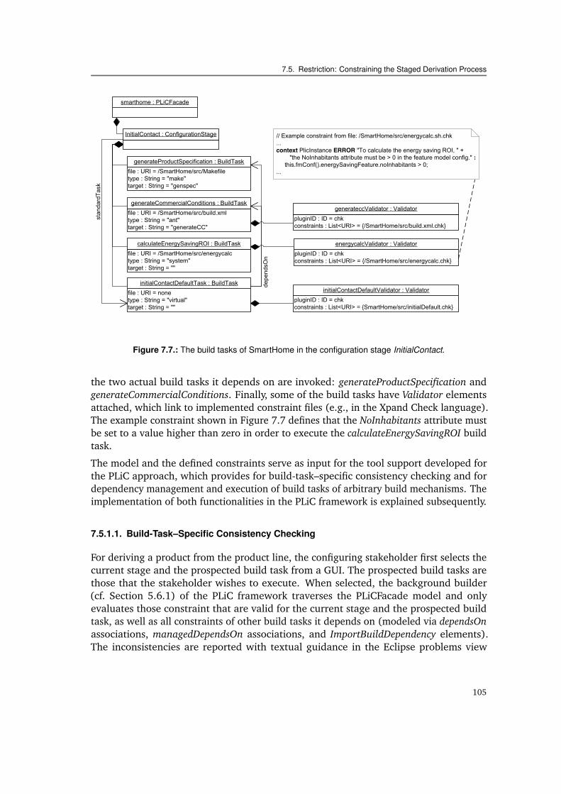
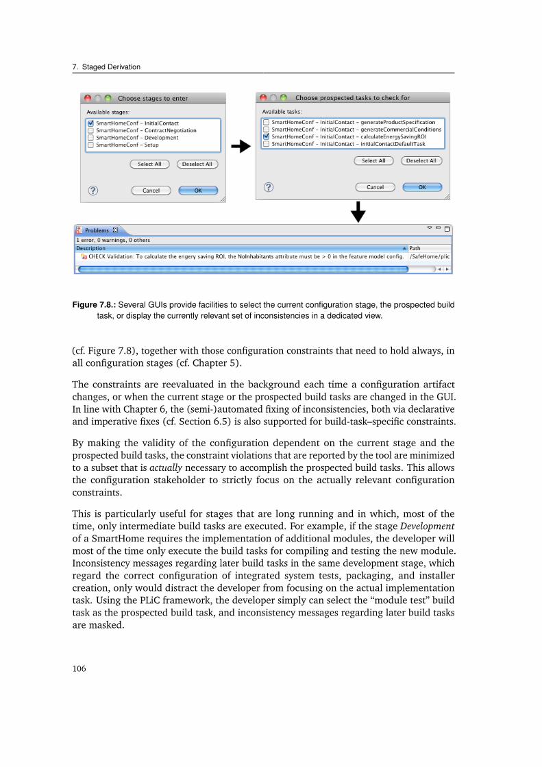
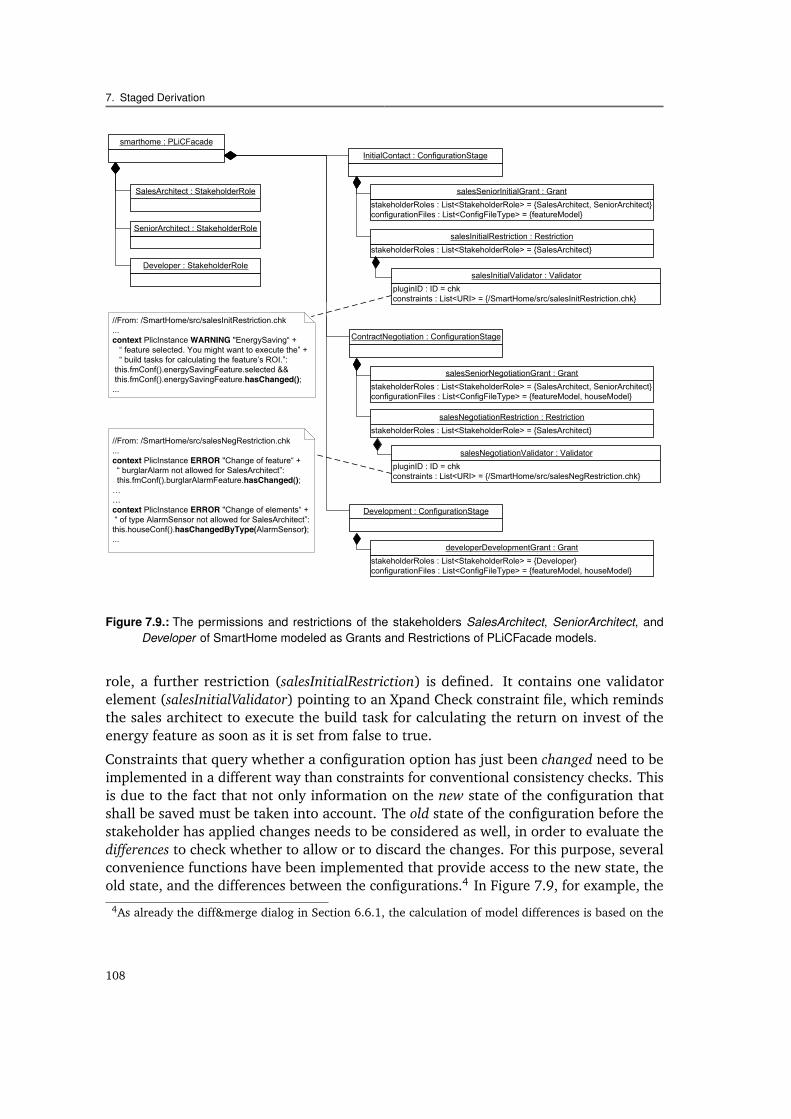
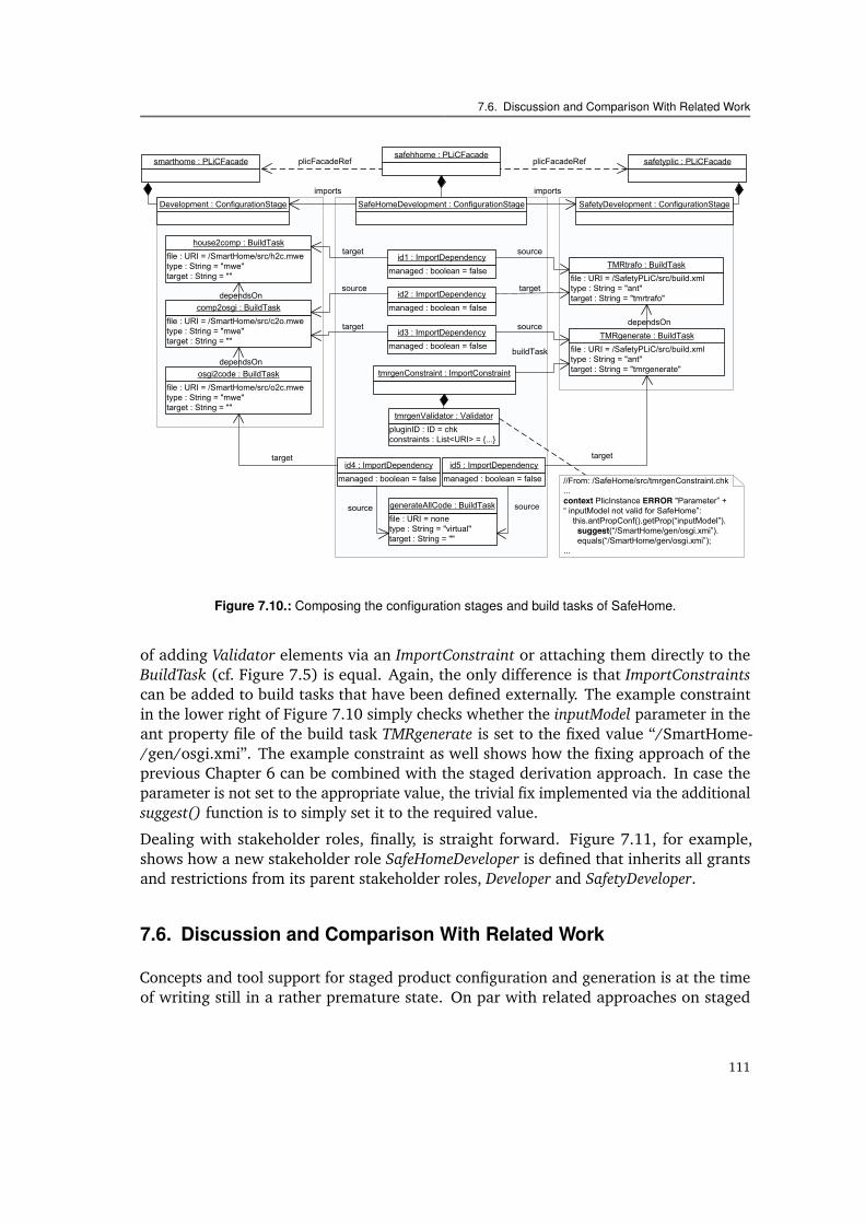
7.1 The build tasks of SmartHome in the configuration stage InitialContact. . . 947.2 The permissions of SalesArchitect, SeniorArchitect, and Developer. . . . . . 967.3 Build tasks required to build a SafeHome product. . . . . . . . . . . . . . . 977.4 Outline of the PLiC framework for staged derivation. . . . . . . . . . . . . 997.5 PLiCFacade model extension for configuration stages. . . . . . . . . . . . . 1027.6 PLiCFacade model extension for build tasks. . . . . . . . . . . . . . . . . . 1037.7 The build tasks of SmartHome in the configuration stage InitialContact. . . 1057.8 Several GUIs of the PLiC framework regarding staged derivation. . . . . . 1067.9 Process Guidance for the SalesArchitect, SeniorArchitect, and Developer. . . 1087.10 Composing the configuration stages and build tasks of SafeHome. . . . . . 111
xiii
List of Figures
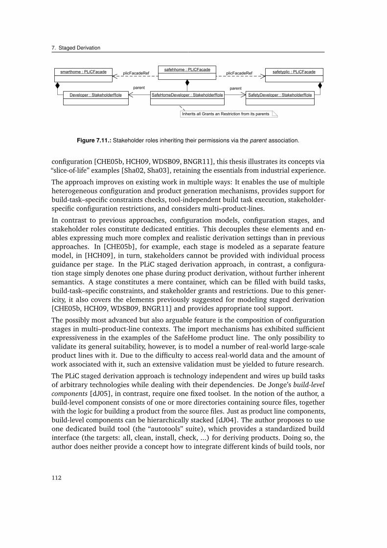
7.11 Stakeholder roles inheriting their permissions via the parent association. . 112
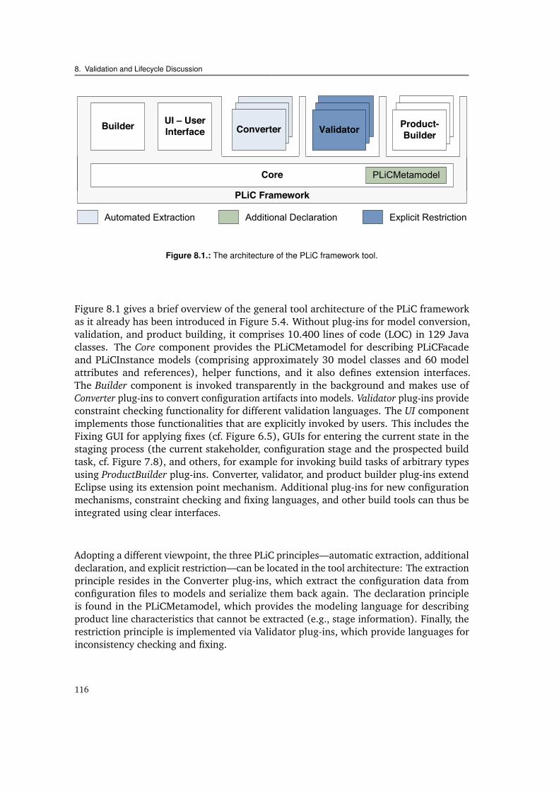
8.1 The architecture of the PLiC framework tool. . . . . . . . . . . . . . . . . . 116
xiv
List of Tables
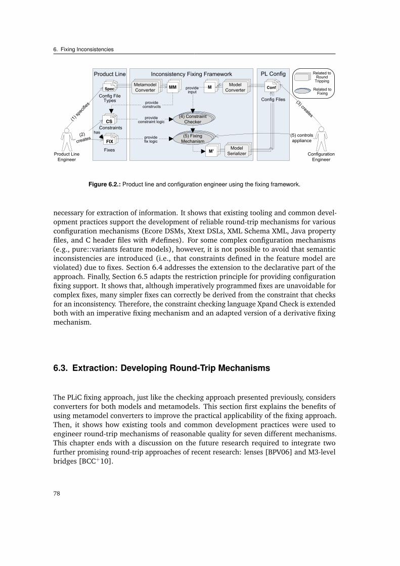
6.1 Different types of inconsistency fixes identified in I4Copter, with examples. 776.2 Conversion and serialization strategies applied to configuration mechanisms. 79
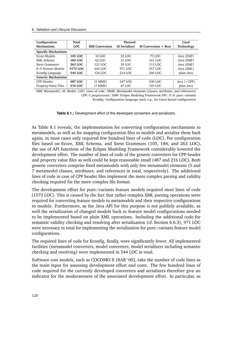
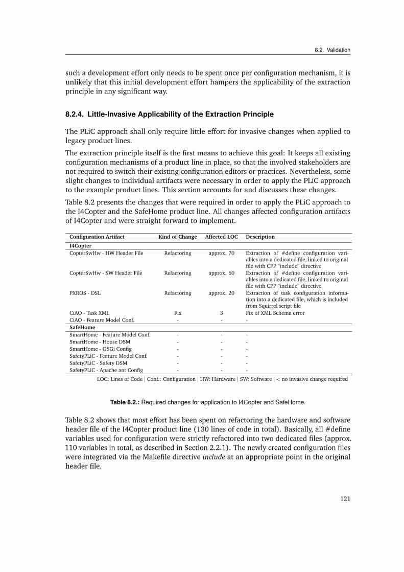
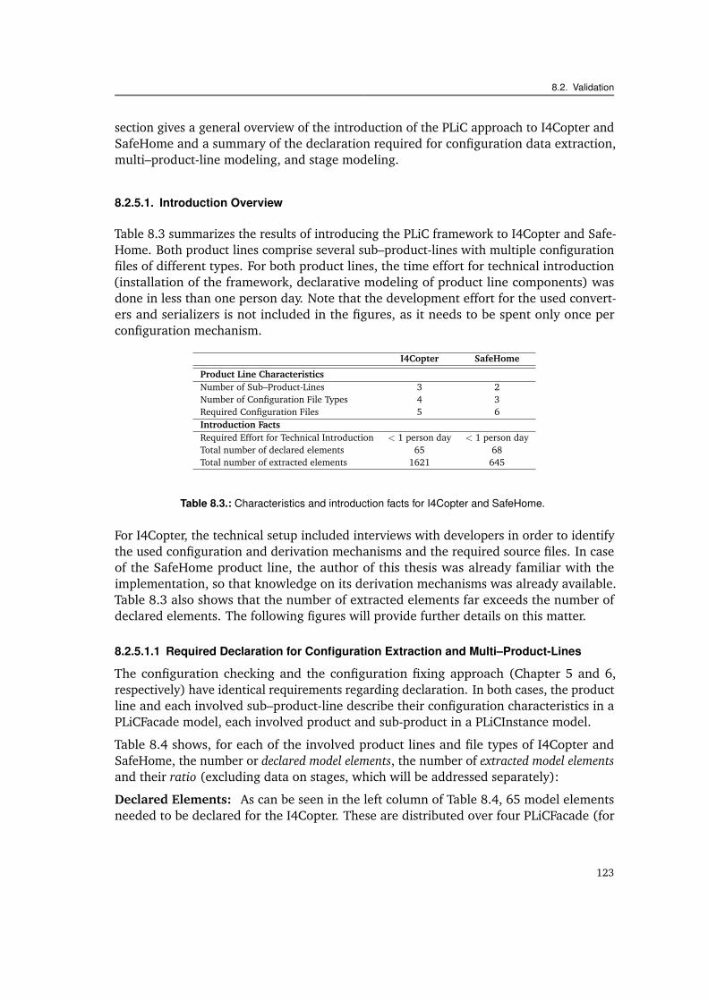
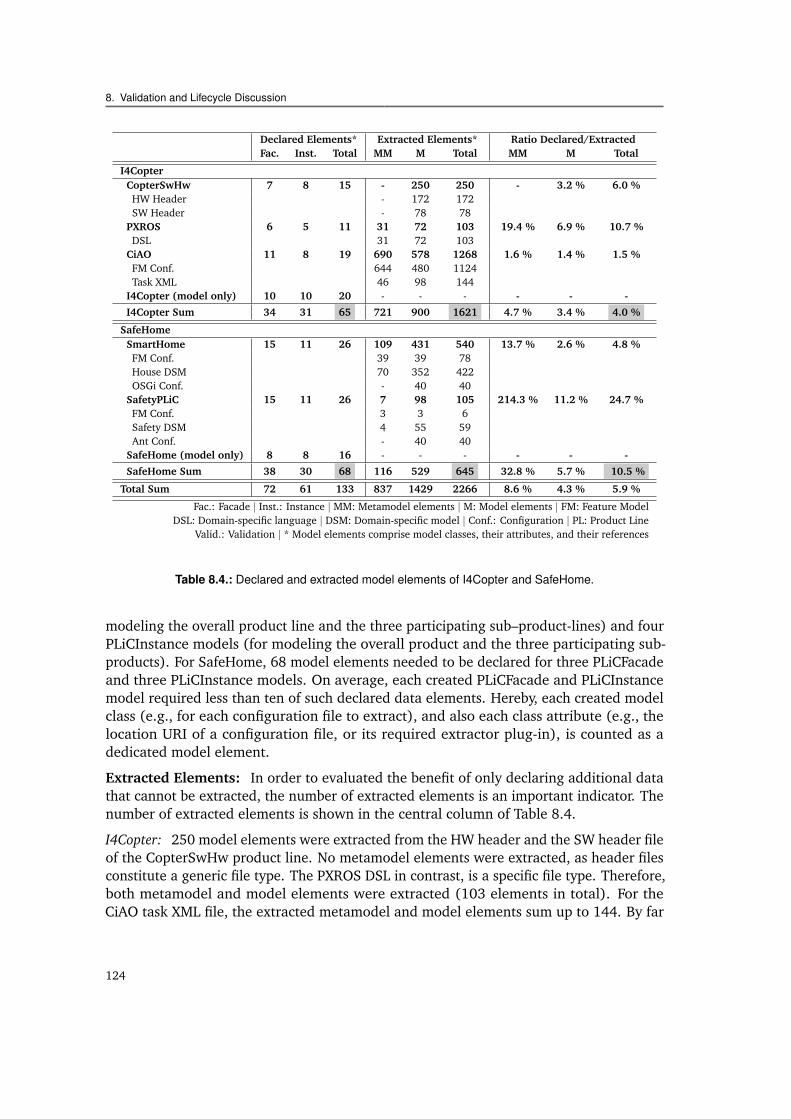
8.1 Development effort of the developed converters and serializers. . . . . . . 1208.2 Required changes for application to I4Copter and SafeHome. . . . . . . . . 1218.3 Characteristics and introduction facts for I4Copter and SafeHome. . . . . 1238.4 Declared and extracted model elements of I4Copter and SafeHome. . . . . 1248.5 Number or elements declared in the SafeHome staged derivation example. 1268.6 Constraint mining facts of I4Copter and SafeHome. . . . . . . . . . . . . . 1278.7 Constraint execution performance of I4Copter and synthetic constraints. . 1298.8 Time effort for fixing inconsistencies. . . . . . . . . . . . . . . . . . . . . . 131
xv
1Introduction
1.1. Motivation
Technical systems comprise a steadily increasing amount of software that adds to the costof the product under development. In order to minimize this cost, reuse of knowledge andassets from early on is necessary when developing similar products. This insight resulted inthe discipline of software product line engineering [WL99, Bos00, Atk01, CN01, PBvdL05].In a nutshell, software product line engineering comprises a collection of engineeringtechniques for the efficient development of a set of similar products. A common set of coreassets is developed in the so called domain engineering phase. Then, in the applicationengineering phase, these assets are reused to derive a concrete product [CN01].
One product line technique that particularly has helped to achieve major improvementsis the automation of application engineering. It is also often referred to as automatedproduct derivation. Its core is the automated mapping of a declarative configuration to aspecifically tailored product using product generators (basing on generative technologies[CE00]), such as preprocessors or code generator templates. The automation of productderivation, therefore, has two important facets: automated support during configuration ofa product, such as configuration consistency checks and automated fixes, and automatedgeneration of the product, via such generative technologies. If customer demands canbe sufficiently anticipated, the one-time effort put into development of such automatedconfiguration and generation mechanisms during domain engineering pays off each timea product is derived with less effort.
Despite the great potential of automation in product derivation, numerous reports pointout the immense manual effort and difficulty of product derivation in industry [CDM04,
1
1. Introduction
Product Specification Stage
<task ... > </task>...
Product Specification
Salesman
Product ExpertsCustomer
Development Stage
Medical Expert
DeveloperAdministrator Customer
On-Site Configuration Stage
Contract
Customized Software
Running System
#
#
......
...
Con
figur
atio
n
Bui
ld T
ask
Bui
ld T
ask
DependenciesDependencies
DescriptorFiles
Bui
ld T
ask
Bui
ld T
ask
Con
figur
atio
n
Con
figur
atio
n
Bui
ld T
ask
Bui
ld T
ask
Con
figur
atio
n
Con
figur
atio
n
Con
figur
atio
n
Con
figur
atio
n
Con
figur
atio
n
Spreadsheets
Domain-Specific Models C Header Files
XML Files
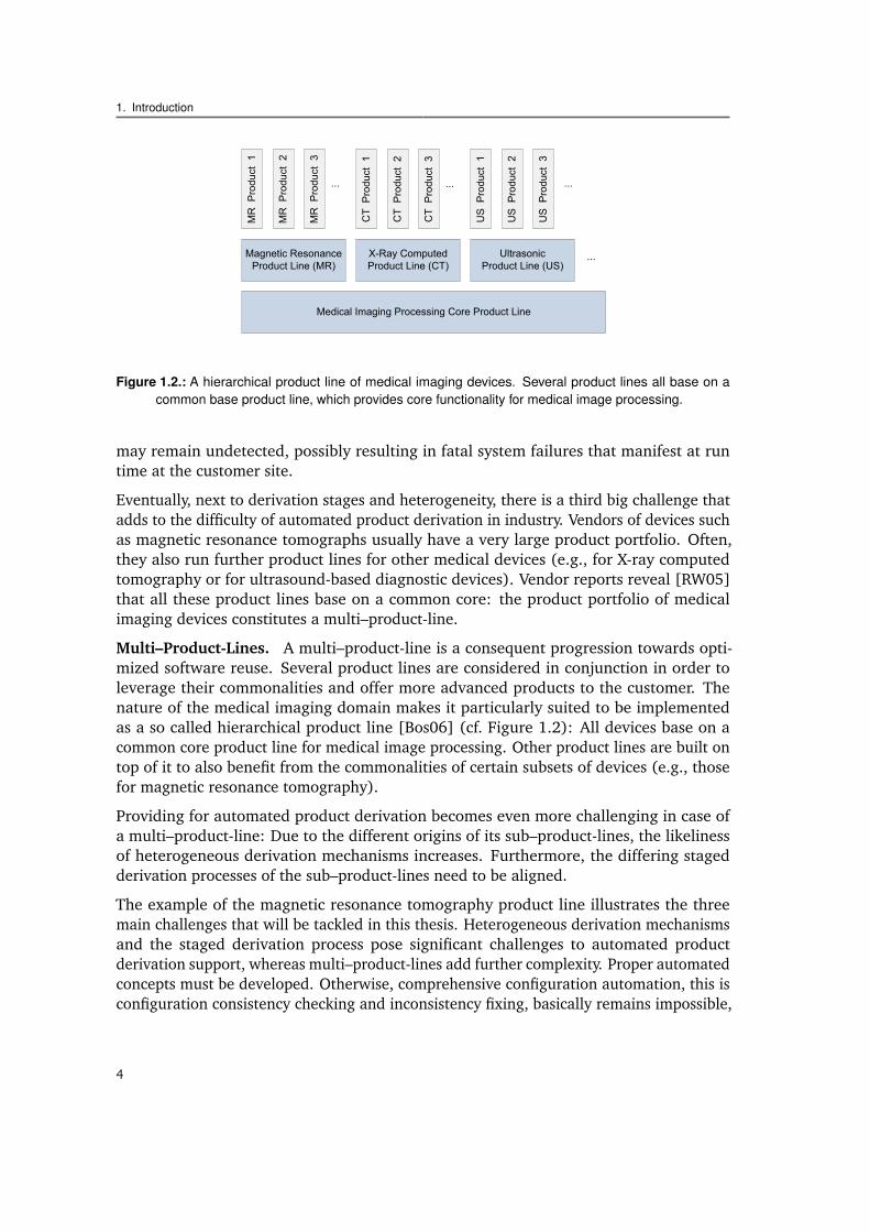
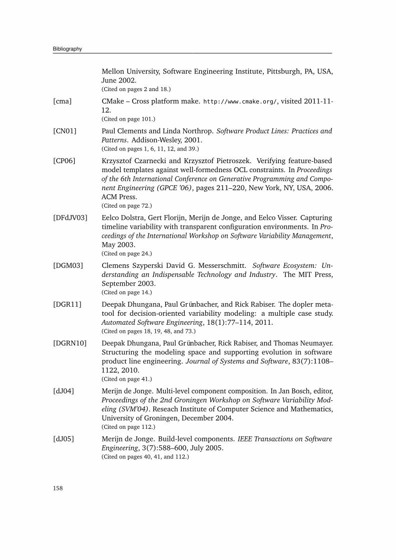
Figure 1.1.: Product derivation from a magnetic resonance tomography product line.
DSB05, ORRT09]. The low degree of automation has become the top research issue inproduct derivation [RGD10]. Up to now, industrial practice still heavily bases on textualproduction plans [CM02] and tacit expert knowledge [DSB05], even when no additionalindividual customer requirements need to be implemented.
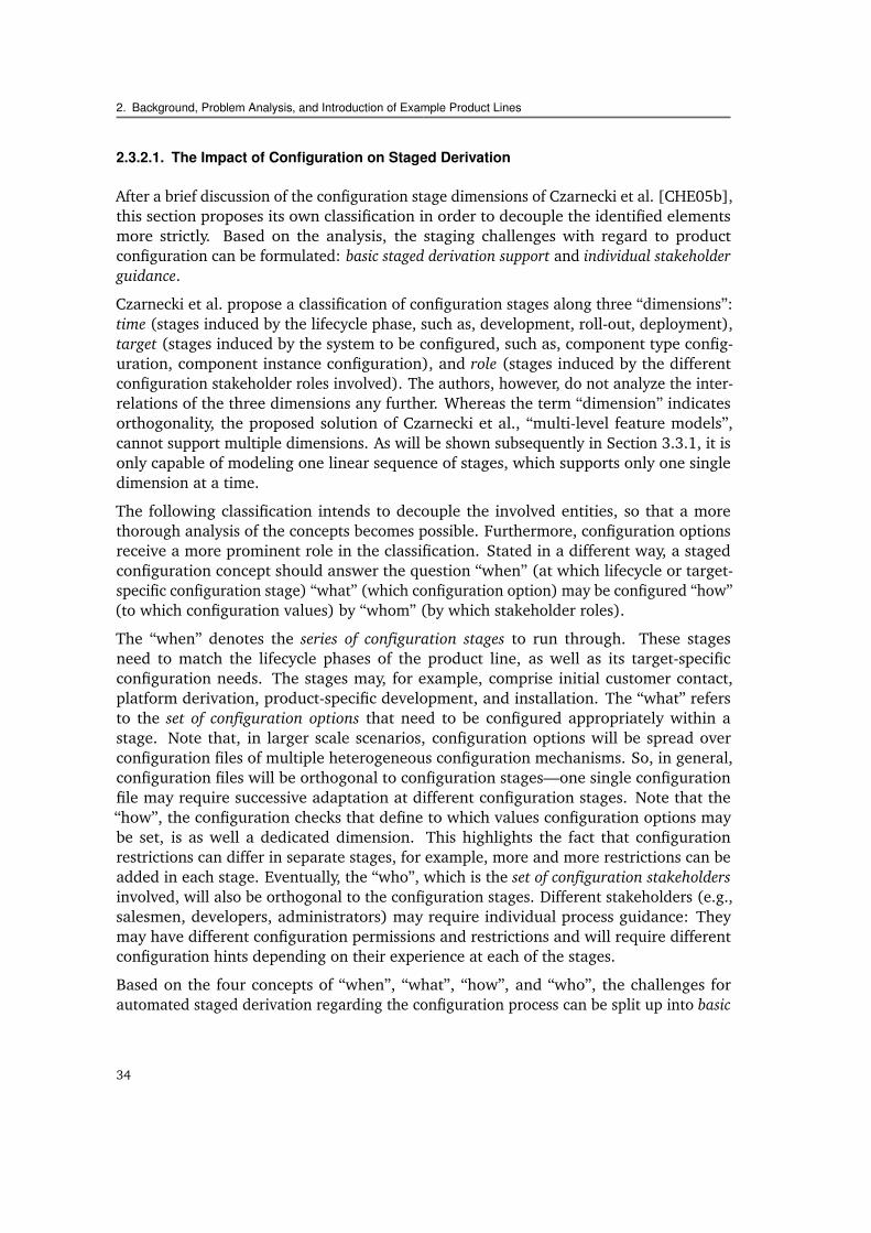
Why is this the case? Figure 1.1 illustrates the derivation process of the software partof a magnetic resonance tomography product line. The product line reveals both astaged derivation process and heterogeneous derivation mechanisms. Up to now, bothcharacteristics constitute serious “show stoppers” for automated product derivation.
Staged Product Derivation Process. As can be seen, the product derivation processis split up into distinct stages: product specification stage, development stage, and on-site configuration stage. In each of the stages, different stakeholders configure variousconfiguration artifacts, such as spreadsheets, domain-specific models, or XML files. Buildtasks take them as input and produce product artifacts, ranging from textual documents
2
1.1. Motivation
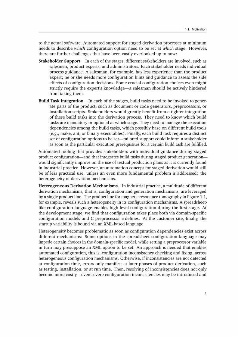
to the actual software. Automated support for staged derivation processes at minimumneeds to describe which configuration option need to be set at which stage. However,there are further challenges that have been vastly overlooked up to now:
Stakeholder Support. In each of the stages, different stakeholders are involved, such assalesmen, product experts, and administrators. Each stakeholder needs individualprocess guidance. A salesman, for example, has less experience than the productexpert; he or she needs more configuration hints and guidance to assess the sideeffects of configuration decisions. Some crucial configuration choices even mightstrictly require the expert’s knowledge—a salesman should be actively hinderedfrom taking them.
Build Task Integration. In each of the stages, build tasks need to be invoked to gener-ate parts of the product, such as document or code generators, preprocessors, orinstallation scripts. Stakeholders would greatly benefit from a tighter integrationof these build tasks into the derivation process. They need to know which buildtasks are mandatory or optional at which stage. They need to manage the executiondependencies among the build tasks, which possibly base on different build tools(e.g., make, ant, or binary executables). Finally, each build task requires a distinctset of configuration options to be set—tailored support could inform a stakeholderas soon as the particular execution prerequisites for a certain build task are fulfilled.
Automated tooling that provides stakeholders with individual guidance during stagedproduct configuration—and that integrates build tasks during staged product generation—would significantly improve on the use of textual production plans as it is currently foundin industrial practice. However, an automation concept for staged derivation would stillbe of less practical use, unless an even more fundamental problem is addressed: theheterogeneity of derivation mechanisms.
Heterogeneous Derivation Mechanisms. In industrial practice, a multitude of differentderivation mechanisms, that is, configuration and generation mechanisms, are leveragedby a single product line. The product line for magnetic resonance tomography in Figure 1.1,for example, reveals such a heterogeneity in its configuration mechanisms. A spreadsheet-like configuration language enables high-level configuration during the first stage. Atthe development stage, we find that configuration takes place both via domain-specificconfiguration models and C preprocessor #defines. At the customer site, finally, thestartup variability is bound via an XML-based language.
Heterogeneity becomes problematic as soon as configuration dependencies exist acrossdifferent mechanisms: Some options in the spreadsheet configuration language mayimpede certain choices in the domain-specific model, while setting a preprocessor variablein turn may presuppose an XML option to be set. An approach is needed that enablesautomated configuration, this is, configuration inconsistency checking and fixing, acrossheterogeneous configuration mechanisms. Otherwise, if inconsistencies are not detectedat configuration time, errors only manifest at later phases of product derivation, suchas testing, installation, or at run time. Then, resolving of inconsistencies does not onlybecome more costly—even severe configuration inconsistencies may be introduced and
3
1. Introduction
Medical Imaging Processing Core Product Line
Magnetic ResonanceProduct Line (MR)
X-Ray ComputedProduct Line (CT)
UltrasonicProduct Line (US)
MR
Pro
duct
1
MR
Pro
duct
2
MR
Pro
duct
3
CT
Pro
duct
1
CT
Pro
duct
2
CT
Pro
duct
3
US
Pro
duct
1
US
Pro
duct
2
US
Pro
duct
3
...
.........
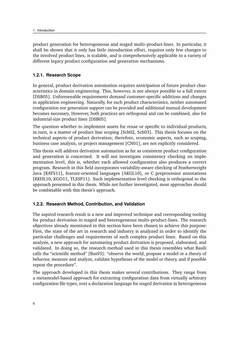
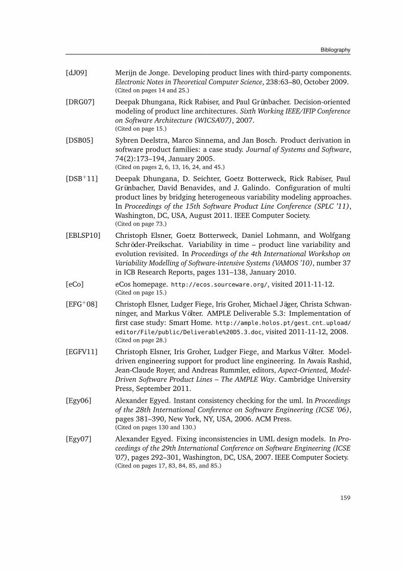
Figure 1.2.: A hierarchical product line of medical imaging devices. Several product lines all base on acommon base product line, which provides core functionality for medical image processing.
may remain undetected, possibly resulting in fatal system failures that manifest at runtime at the customer site.
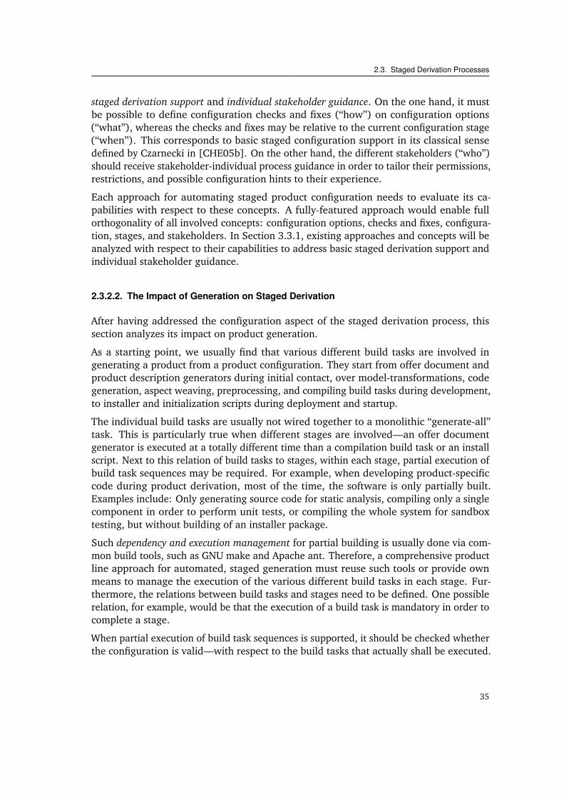
Eventually, next to derivation stages and heterogeneity, there is a third big challenge thatadds to the difficulty of automated product derivation in industry. Vendors of devices suchas magnetic resonance tomographs usually have a very large product portfolio. Often,they also run further product lines for other medical devices (e.g., for X-ray computedtomography or for ultrasound-based diagnostic devices). Vendor reports reveal [RW05]that all these product lines base on a common core: the product portfolio of medicalimaging devices constitutes a multi–product-line.
Multi–Product-Lines. A multi–product-line is a consequent progression towards opti-mized software reuse. Several product lines are considered in conjunction in order toleverage their commonalities and offer more advanced products to the customer. Thenature of the medical imaging domain makes it particularly suited to be implementedas a so called hierarchical product line [Bos06] (cf. Figure 1.2): All devices base on acommon core product line for medical image processing. Other product lines are built ontop of it to also benefit from the commonalities of certain subsets of devices (e.g., thosefor magnetic resonance tomography).
Providing for automated product derivation becomes even more challenging in case ofa multi–product-line: Due to the different origins of its sub–product-lines, the likelinessof heterogeneous derivation mechanisms increases. Furthermore, the differing stagedderivation processes of the sub–product-lines need to be aligned.
The example of the magnetic resonance tomography product line illustrates the threemain challenges that will be tackled in this thesis. Heterogeneous derivation mechanismsand the staged derivation process pose significant challenges to automated productderivation support, whereas multi–product-lines add further complexity. Proper automatedconcepts must be developed. Otherwise, comprehensive configuration automation, this isconfiguration consistency checking and inconsistency fixing, basically remains impossible,
4
1.2. Question and Objectives of This Thesis
and stakeholders are neither provided with individual guidance nor with support for buildtask execution. Lacking automated support, in turn, results in slower, manual, and moreerror-prone product derivation. To avoid this, the challenges imposed by derivation stages,heterogeneity, and multi–product-lines must be addressed so that comprehensive adoptionof automated product derivation becomes feasible.
1.2. Question and Objectives of This Thesis
This thesis targets a new “method or means of development” for product lines accordingto the classification provided in [Sha03]. It answers the following question:
(Q) How can we automate the product derivation process for multi–product-lines withheterogeneous product configuration and generation mechanisms, whereas eachproduct line comprises different configuration stages, stakeholders, and build tasks?
Automated product derivation comprises both automated configuration, this is, checkingand fixing inconsistencies in configurations, as well as automated generation of productartifacts, via executing build tasks of various kinds. The aspired result of this thesis is anew approach (a “procedure or technique” according to the classification in [Sha03]), aswell as corresponding tooling that achieves the automation of product derivation in suchcomplex settings. The overall result can be broken down into the following objectives:
• Analysis: Identify the challenges of automating heterogeneous and staged productderivation processes for multi–product-lines and identify the crucial requirementsfor a corresponding approach.
Analyze the concepts of heterogeneity and stages and the challenges they pose toexisting, industrial product derivation. Analyze how previous approaches for auto-mated product derivation address these challenges. Identify the crucial requirementsof a new approach to overcome the weaknesses of the previous approaches.
• Approach: Develop a new approach for automated product derivation in heteroge-neous and staged multi–product-lines that meets the identified requirements.
• Elaboration: Elaborate the approach for addressing the challenges.
Automate configuration checking for heterogeneous multi–product-lines. Automateconfiguration fixing for heterogeneous multi–product-lines. Automate the configura-tion and generation process for heterogeneous and staged multi–product-lines.
• Validation: Show that the approach fulfills the identified requirements.
Prototypically implement a corresponding automation tool. Apply the approach andthe tool to suitable example product lines. Show that the identified requirementsare actually fulfilled.
The goal of the thesis is to show that the new approach improves on existing productderivation approaches by enabling automated configuration checking and fixing and
5
1. Introduction
product generation for heterogeneous and staged multi–product-lines. In particular, itshall be shown that it only has little introduction effort, requires only few changes tothe involved product lines, is scalable, and is comprehensively applicable to a variety ofdifferent legacy product configuration and generation mechanisms.
1.2.1. Research Scope
In general, product derivation automation requires anticipation of future product char-acteristics in domain engineering. This, however, is not always possible to a full extent[DSB05]. Unforeseeable requirements demand customer-specific additions and changesin application engineering. Naturally, for such product characteristics, neither automatedconfiguration nor generation support can be provided and additional manual developmentbecomes necessary. However, both practices are orthogonal and can be combined, also forindustrial-size product lines [DSB05].
The question whether to implement assets for reuse or specific to individual products,in turn, is a matter of product line scoping [Sch02, Sch03]. This thesis focuses on thetechnical aspects of product derivation; therefore, economic aspects, such as scoping,business case analysis, or project management [CN01], are not explicitly considered.
This thesis will address derivation automation as far as consistent product configurationand generation is concerned. It will not investigate consistency checking on imple-mentation level, this is, whether each allowed configuration also produces a correctprogram. Research in this field incorporates variability-aware checking of FeatherweightJava [KATS11], feature-oriented languages [AKGL10], or C preprocessor annotations[KKHL10, KGO11, TLSSP11]. Such implementation level checking is orthogonal to theapproach presented in this thesis. While not further investigated, most approaches shouldbe combinable with this thesis’s approach.
1.2.2. Research Method, Contribution, and Validation
The aspired research result is a new and improved technique and corresponding toolingfor product derivation in staged and heterogeneous multi–product-lines. The researchobjectives already mentioned in this section have been chosen to achieve this purpose:First, the state of the art in research and industry is analyzed in order to identify theparticular challenges and requirements of such complex product lines. Based on thisanalysis, a new approach for automating product derivation is proposed, elaborated, andvalidated. In doing so, the research method used in this thesis resembles what Basilicalls the “scientific method” [Bas93]: “observe the world, propose a model or a theory ofbehavior, measure and analyze, validate hypotheses of the model or theory, and if possiblerepeat the procedure”.
The approach developed in this thesis makes several contributions. They range froma metamodel-based approach for extracting configuration data from virtually arbitraryconfiguration file types, over a declaration language for staged derivation in heterogeneous
6
1.3. Structure of This Thesis
multi–product-lines, to a semi-automated constraint checking and fixing approach forsuch kinds of product lines. The conclusion of this thesis provides a complete list of all itscontributions (Section 9.2).
The validation of the approach and the corresponding tooling centers around its appli-cation to two example multi–product-lines. According to Shaw [Sha02, Sha03], variousvalidation methods, ranging from analysis and practical experience to plain persuasion,are all being used in software engineering research—with varying degrees of success.The use of examples is a common and among the most successful validation practices insoftware engineering, as long as they constitute a “slice of life” (cf. Shaw [Sha02, Sha03]):Although simplified, the essence of the problem being solved must be retained. As Chap-ter 2 will show, the examples exhibit exactly those characteristics that, up to now, havehampered automation of product derivation for staged and heterogeneous multi–product-lines. Hence, the application examples cannot only show principal applicability of theapproach, but their quantitative and qualitative aspects can serve as an indicator forsimilar settings.
Finally, other validation methods are used to validate characteristics that the exemplaryapplication cannot provide. For example, principal scalability aspects are measured viatooling benchmarks, and the improvements on configuration time have been gathered inan experimental user study.
1.3. Structure of This Thesis
This thesis is structured as follows:
Chapter 2: Background, Problem Analysis, and Introduction of Example Product Lines
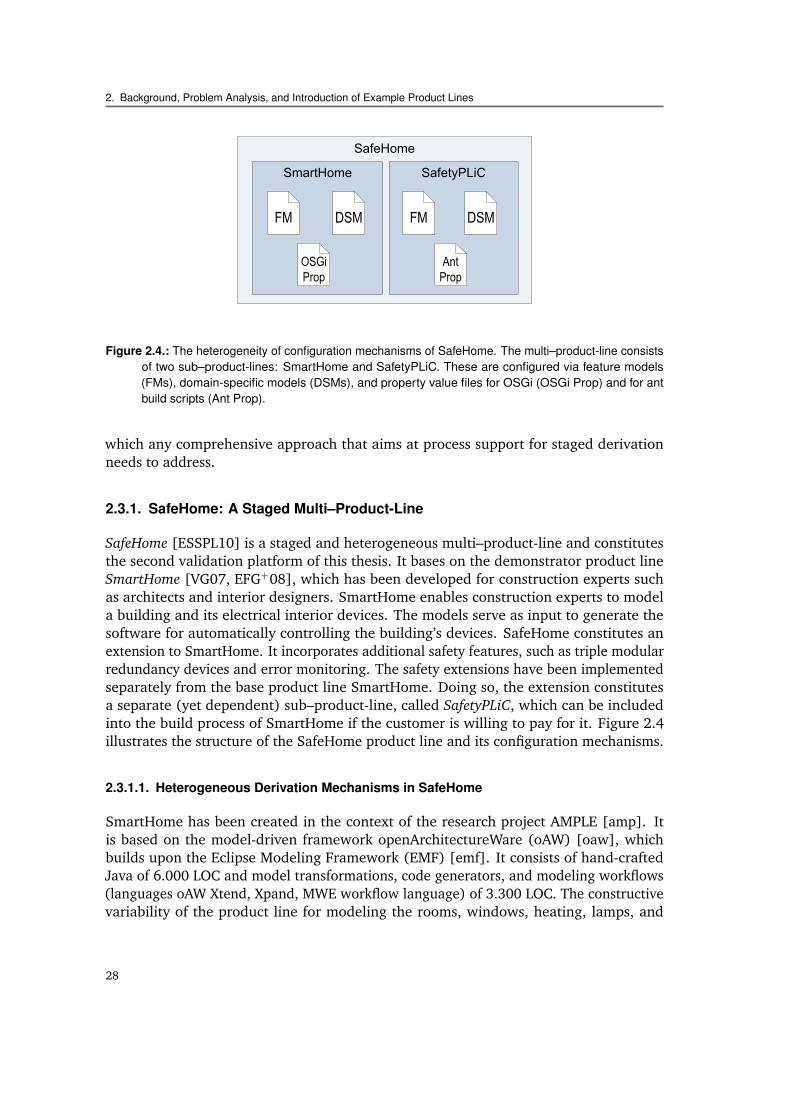
The second chapter provides a brief background in product line engineering witha particular focus on product derivation, its automation, and multi–product-lines.The concepts of heterogeneity and stages are analyzed and their specific challengesare identified. The challenges are illustrated via two exemplary multi–product-lines,I4Copter and SafeHome, which serve as running examples throughout this thesis.
Chapter 3: State of the Art
The third chapter discusses in how far previous approaches have addressed thechallenges of heterogeneity and staged derivation. From their shortcomings, threeessential requirements are derived that a new approach should fulfill: light-weight,little-invasive, and comprehensive applicability.
Chapter 4: The Product Line Component Approach
The fourth chapter gives an overview of a new automated product derivationapproach, the product line component approach (PLiC approach). Its three principlesof extraction, declaration, and restriction are capable of addressing the identifiedrequirements.
7
Related Publications
Chapter 5: Checking Consistency
The fifth chapter constitutes the first of three chapters elaborating the PLiC approach.It focuses on the checking of configuration consistency during product derivation forthe case that multiple, heterogeneous configuration mechanisms, possibly spreadover multiple sub–product-lines, are involved.
Chapter 6: Fixing Inconsistencies
The sixth chapter builds on the preceding chapter on configuration checking ofheterogeneous multi–product-lines. It adds capabilities for solving detected inconsis-tencies by applying (semi-)automated fixes on configuration files of various differentmechanisms.
Chapter 7: Staged Derivation
The seventh chapter presents the facets of the approach dealing with staged con-figuration and product generation. It adds the capabilities to ensure configurationconsistency dependent on the current configuration stage, on the prospected buildtask to be executed, or on the configuring stakeholder. Additionally, product genera-tion capabilities are provided for various different generation mechanisms.
Chapter 8: Validation and Lifecycle Discussion
The eighth chapter validates the applicability of the overall approach and of thedeveloped tooling. The validation proofs that the approach actually is light-weight,little invasive, and technically scalable for a variety of different derivation mecha-nisms.
Chapter 9: Conclusions, Contributions, and Further Research Directions
Finally, the ninth chapter concludes the thesis, states its contributions, and providesan outlook on future research directions.
1.4. Related Publications
Parts of this thesis have been published in the following publications:
[ELS09] Christoph Elsner, Daniel Lohmann, and Christa Schwanninger. Eine Infras-truktur für modellgetriebene hierarchische Produktlinien. In Klaus Marquardt,Dietmar Schütz, Markus Völter, Jürgen Münch, and Peter Liggesmeyer, ed-itors, Software Engineering 2009 - Workshopband, volume 150 of LectureNotes in Informatics, pages 107–113, Bonn, Germany, 2009. Gesellschaft fürInformatik.
[ELSP09] Christoph Elsner, Daniel Lohmann, and Wolfgang Schröder-Preikschat. Prod-uct derivation for solution-driven product line engineering. In Sven Apel,editor, Proceedings of the 1st Workshop on Feature-Oriented Software Develop-ment (FOSD ’09), pages 35–41, New York, NY, USA, 2009. ACM Press.
8
Related Publications
[ELSP11a] Christoph Elsner, Daniel Lohmann, and Wolfgang Schröder-Preikschat. Fixingconfiguration inconsistencies across file type boundaries. In Proceedingsof the 37th EUROMICRO Conference on Software Engineering and AdvancedApplications (SEAA ’11), pages 116–123, Washington, DC, USA, August 2011.IEEE Computer Society.
[ELSP11b] Christoph Elsner, Daniel Lohmann, and Wolfgang Schröder-Preikschat. Aninfrastructure for composing build systems of software product lines. InProceedings of the Joint Workshop of the 3rd International Workshop on Model-driven Approaches in Software Product Line Engineering and 3rd Workshop onScalable Modeling Techniques for Software Product Lines (MAPLE/SCALE ’11),New York, NY, USA, August 2011. ACM Press.
[ESSPL10] Christoph Elsner, Christa Schwanninger, Wolfgang Schröder-Preikschat, andDaniel Lohmann. Multi-level product line customization. In Kohei Sugawara,editor, Proceedings of the 2010 Conference on New Trends in Software Method-ologies, Tools and Techniques (SoMeT ’10), Frontiers in Artificial Intelligenceand Applications, pages 37–58, Amsterdam, The Netherlands, 2010. IOSPress.
[EULSP10] Christoph Elsner, Peter Ulbrich, Daniel Lohmann, and Wolfgang Schröder-Preikschat. Consistent product line configuration across file type and productline boundaries. In Kyo Kang, editor, Proceedings of the 14th Software ProductLine Conference (SPLC ’10), volume 6287 of Lecture Notes in Computer Science,pages 181–195, Heidelberg, Germany, September 2010. Springer-Verlag.
9
2Background, Problem Analysis, and
Introduction of Example Product Lines
This chapter provides the necessary background on product line engineering, analyzesthe concepts of heterogeneity and staged derivation, and presents the example productlines. It starts by introducing crucial terms and concepts of product line engineeringwith a particular focus on multi–product-lines and automated product derivation. Then,it identifies and analyzes the challenges of heterogeneous derivation mechanisms andstaged derivation processes. The challenges are illustrated with two example productlines, I4Copter and SafeHome, which both serve as running examples and validationsubjects of this thesis.
2.1. Software Product Line Engineering
Traditional software engineering considers each software product to be developed sep-arately. Software product line engineering [Bos00, Atk01, CN01, PBvdL05, WL99], incontrast, denotes a shift in development strategy. It comprises a collection of engineeringtechniques that supports efficient reuse when a whole set of similar, yet distinct softwareproducts are to be developed. Various companies report on significant improvementon development time, cost, product quality, and reduction of expert load by systemat-ically reusing commonalities and managing variability from early on in the life cycle[spl, vdLSR07].
11
2. Background, Problem Analysis, and Introduction of Example Product Lines
2.1.1. History
One fundamental concept of software product line engineering—the early analysis ofcommonalities during design and implementation of a set of similar programs—has beenproposed by Parnas in 1976 [Par76], calling the set of programs a “program family”.The term “software product line” emerged in the 1990s and, initially, considered sets ofsoftware programs solely from a business and organizational perspective—for analyzingmarkets, assigning responsibilities, and managing risks [BCK03]—regardless of programimplementation. In contrast to this, the term “software product family”, was defined todenote a set of products that have a “shared architecture, using assets from a platform”[Wij02].
Whereas this conceptual separation of business and software architecture perspective wasnever strictly maintained by all authors, it was further loosened by the absorption of theProduct Family Engineering (PFE) conference by the Software Product Line Conference(SPLC) in 2005. Since then, the term product line has widely prevailed, both for thebusiness and the technical context. Unless stated otherwise, this thesis focuses on thetechnical aspects of product line engineering—business issues are merely touched in sofar as the software product line paradigm is driven by economic considerations.
2.1.2. Definition of Terms
The term “software product line”, as it will be used in this thesis, is in line with theprobably most cited definition, which brings together marketing and implementationaspects. It stems from Clements and Northrop [CN01]: “A software product line is a set ofsoftware-intensive systems sharing a common, managed set of features that satisfy thespecific needs of a particular market segment or mission and that are developed from acommon set of core assets in a prescribed way”. In correspondence, the term “softwareproduct line engineering” denotes a collection of engineering techniques and practicesthat supports the efficient development of such software-intensive systems (or “products”).
Typically, development in software product line engineering is split into two phases. Indomain engineering, reusable core assets are developed for reuse. In application engineering,also called product derivation, products are created by reuse of the core assets previouslydeveloped, in order to maximize the overall return on invest [Bos00]. Domain engineeringand application engineering both comprise a dedicated requirements engineering, design,realization, and testing phase [PBvdL05]—the former in order to develop the core assets,the latter to derive the actual products from them.
2.1.3. Maturity and Complexity of Product Lines
Software product lines come in various different degrees of maturity and complexity.The reuse maturity may range from a set of products that only share few infrastructuralcomponents to a fully-fledged, integrated product generator that is capable of generating
12
2.1. Software Product Line Engineering
all products automatically from configuration input. The complexity of a product line, onthe other hand, ranges from ordinary product lines to various forms of combinations ofmultiple product lines, which possibly even span organizational boundaries.
2.1.3.1. Maturity Levels
Bosch [Bos02] distinguishes four different product line maturity levels regarding reuse. Inthe initial level, products only share the same (1) standardized infrastructure software (e.g.,operating system, database). One step further, they share the same (2) platform, that is, allcommon domain functionality (e.g., the basic flight functionality of a quadrotor helicopter).When having a (3) software product line in the narrow sense of words according to Bosch,the product line comprises both the common and the variable functionality that is reusablein several products (e.g., optional components, such as a GPS module). Finally, a (4)configurable product base comprises all common, variable, and product-specific partstogether with a generator that allows deriving the final products solely by giving aconfiguration as input.
2.1.3.2. Structural and Organizational Complexity
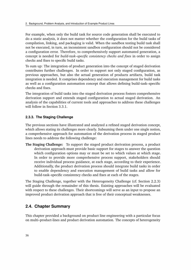
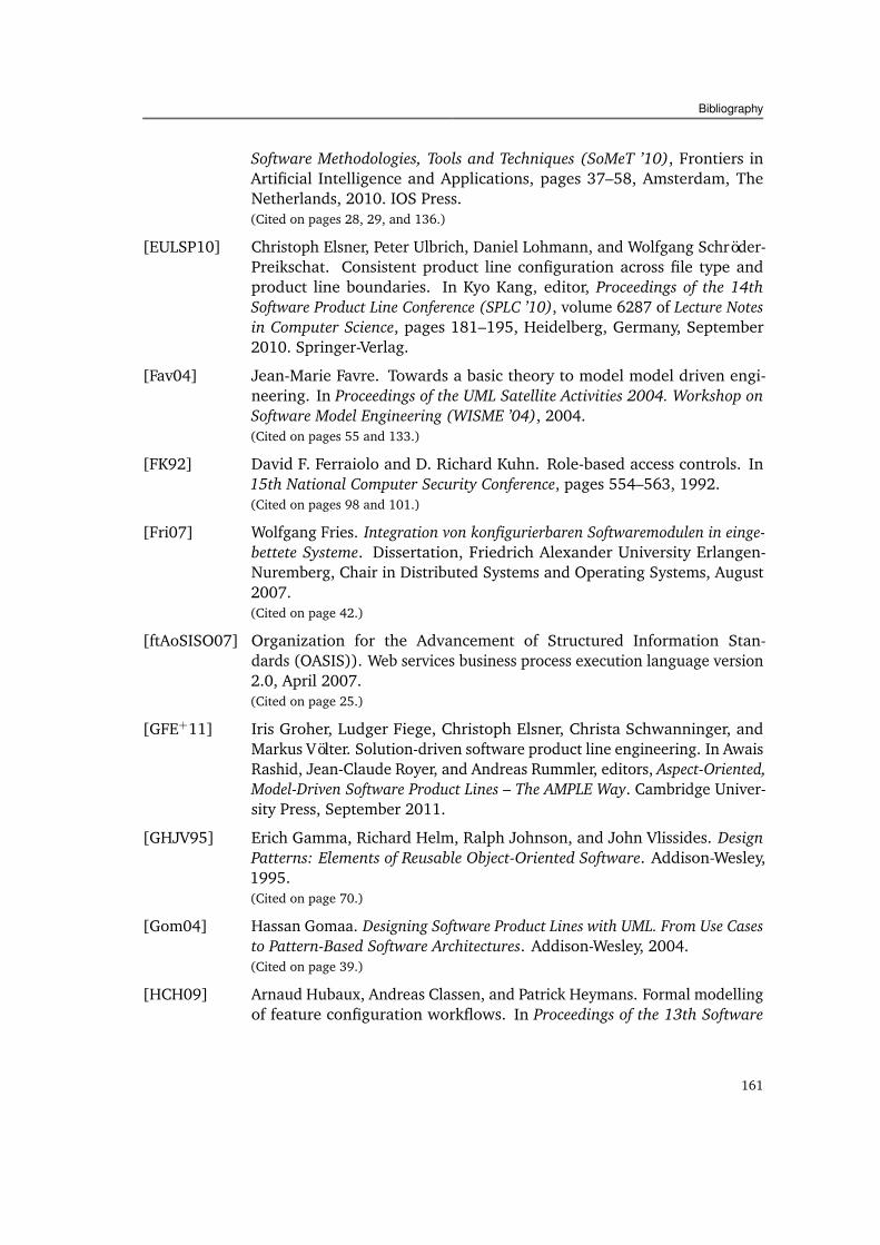
In order to account for the structural complexity of larger-scale product lines, Deelstraet al. [DSB05], based on earlier ideas of Bosch [Bos02], distinguish three archetypes oflarger-scale product lines, sometimes also called multi–product-lines:
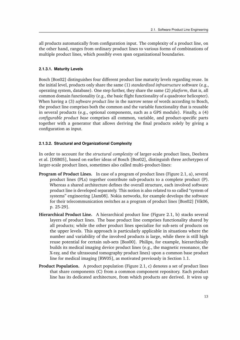
Program of Product Lines. In case of a program of product lines (Figure 2.1, a), severalproduct lines (PLs) together contribute sub-products to a complete product (P).Whereas a shared architecture defines the overall structure, each involved softwareproduct line is developed separately. This notion is also related to so called “system ofsystems” engineering [Jam08]. Nokia networks, for example develops the softwarefor their telecommunication switches as a program of product lines [Bos02] [Vik06,p. 25-29].
Hierarchical Product Line. A hierarchical product line (Figure 2.1, b) stacks severallayers of product lines. The base product line comprises functionality shared byall products; while the other product lines specialize for sub-sets of products onthe upper levels. This approach is particularly applicable in situations where thenumber and variability of the involved products is large, while there is still highreuse potential for certain sub-sets [Bos00]. Philips, for example, hierarchicallybuilds its medical imaging device product lines (e.g., the magnetic resonance, theX-ray, and the ultrasound tomography product lines) upon a common base productline for medical imaging [RW05], as motivated previously in Section 1.1.
Product Population. A product population (Figure 2.1, c) denotes a set of product linesthat share components (C) from a common component repository. Each productline has its dedicated architecture, from which products are derived. It wires up
13
2. Background, Problem Analysis, and Introduction of Example Product Lines
PL
PL PL PL
PL PLP P P P
P
PP PP
P
PL PL PL PL PL
PP
PL
P
PL PL
P P P P PP PP P
C C C C C C C
(a) (b) (c)
Figure 2.1.: Different types of multi–product-lines: program of product lines (a), hierarchical product line (b),and product population (c). They differ in the way they arrange product lines (PLs), products (Ps),and components (C), in their overall architecture.
components from the repository and, possibly, additional product-specific compo-nents. The flexibility of this composition-oriented approach is best suited when avery broad domain needs to be covered, so that there is few global reuse potential,but flexible reuse across sub-domains shall be fostered. The Koala component model,for instance, enables building of product populations in the consumer electronicsdomain [vO02].
Next to this structural complexity, we also find the recent trend towards involving otherparties into software development. This adds a further dimension of complexity: organi-zational complexity.
Software Ecosystem. A company that decides to open their product line platform inorder to allow others to develop extensions creates a software ecosystem [DGM03].Both, the architecture and the organization, need to support this “open worldscenario”, for example, to manage dependencies between extensions and to enablecustomers to configure and derive their individual product [Bos09]. Prominentexamples for software ecosystems are the iPhone App Store and the applicationprogramming interfaces (APIs) of Microsoft Office [Bos09].
Software Supply Chain. Software supply chains emphasize the fact that more and moresoftware is being developed from external, commercial, and often highly-config-urable components instead of developing it in house [WHS01, HTM09]. Largecar manufacturers, for example, often have several different suppliers for theirinfotainment systems [HTM09]. The infotainment systems, in turn, need to besupplied with operating systems to run on, which again are developed by a differentparty. Architecture, organization, and dependency management need to take intoaccount that the total product line is spread over different institutions with differentstrategies, technical knowledge, and interests. Similar challenges also occur whenintegrating open source components [dJ09, vdLG06, vdLL07] into a product line.
Due to the prospected benefit, the endeavor increases to make reuse of ever larger chunksof assets. This includes building more complex product lines from simple ones, as wellas spreading of the development over organizational boundaries. In the following, thevarious flavors of these larger-scale product lines will be called multi–product-lines. As will
14
2.1. Software Product Line Engineering
be shown, multi–product-lines challenge several of the classical assumptions often foundin product line engineering. Configuration via a single, integrated mechanism becomesmore and more unlikely, while the number of involved steps to derive a product increases.Multi–product-lines require a more light-weight and more flexible approach, as it will bedeveloped in the remainder of this thesis.
2.1.4. Variability and Variability Modeling
Variability is the “ability of a software system or artifact to be efficiently extended, changed,customized or configured for use in a particular context” [SvGB06]. In product lineengineering, one can generally distinguish between common parts, which are containedin all products, variable parts, which are only part of some products, and product-specificparts, which are never reused and only contribute to one single product. The variabilityamong the products is a central aspect in software product line engineering. It mustbe “managed” over the whole product line lifecycle: It must be identified, documented,implemented, evolved, and so on.
The identification and decision process regarding common, variable, or product-specificparts is called asset scoping [Sch02]. Variability modeling techniques document theoutcome of the scoping process [SD07]. Well-known representation techniques arefeature modeling [KCH+90, CHE05b], orthogonal variability modeling (OVM) [PBvdL05],and decision modeling [Atk01, SJ04a, DRG07].
A variability model describes the common and variable characteristics of the product ofa product line in the so-called “problem space”. It abstracts from the implementationassets, which reside in the “solution space”. Once established, the variability model cansupport various tasks in domain engineering. It may guide tendering, cost planning, serveas a common basis for communication of sales, marketing, and development, and helpscheduling development releases, testing, and evolution [SGEL09].
Variability models usually adopt a top-down view on the product line variability. Whenused for early domain analysis and planning purposes, blurry concepts and terms and onlyvery coarse-grained variability prevail. This is a different purpose than using techniquessuch as feature modeling for technical configuration when deriving actual products froma software product line. For this purpose, the feature model must describe the product toderive exactly and completely.
A lot of research for product configuration actually uses feature modeling as configurationtechnique (e.g., [BSTRC07, WSB+08]). Operating systems, such as Linux or eCos [eCo],as well leverage languages similar to feature modeling for configuration [SSSPS07]. It is,however, still an open research question how to combine the blurry and coarse domainanalysis information with the preciseness and completeness requirements for productderivation within a single variability model. As this thesis targets product derivation,feature modeling or decision modeling will subsequently only be addressed insofar asproduct derivation and its automation are involved.
15
2. Background, Problem Analysis, and Introduction of Example Product Lines
2.1.5. Product Derivation and Automation
Product derivation is a key activity in application engineering. It addresses the constructionof a concrete product from the product line core assets [DSB05]. Automating productderivation means automating this construction process. This presupposes that at least thematurity level of a “software product line” [Bos02] (cf. Section 2.1.3.1) is reached, so thatboth the common elements and a significant amount of variable elements are provided ascore assets.
This thesis will explicitly distinguish two sub-processes in product derivation: productconfiguration and product generation. The process of product configuration can at bestbe semi-automated. A human stakeholder can be provided with tool support when he orshe translates the product requirements into a machine interpretable form, the so calledconfiguration. Such a configuration describes the characteristics of the product (or of apart of the product) in an unambiguous and consistent manner. A product generator thentakes the core asset base and the configuration as input in order to build the final product(or parts of it, such as, executables, documentation, tests, etc.).
Note that the “generation” (also called the “building”) of the product, or of parts of theproduct, is taken in a wider sense throughout this thesis. The generation process covers anybuild task in product derivation that produces output from core assets and configurationinput. An “offer generator” generates an offer document from the customer’s configurationinput, a compiler generates object files from source code. An installer executable generatesa deployed system from install packages and a deployment configuration, and, whentaking the analogy even further, a running system may be “generated” by executing thecorresponding binaries, feeding in a startup configuration file as further input.
The following sections will give an overview of the commonly used mechanisms for productconfiguration and generation, as well as the means to provide them with automatedsupport.
2.1.5.1. Product Configuration
Classical variability modeling, as argued in Section 2.1.4, originally adopts a top-downview from a domain analysis perspective. When used in practice, it is often only applied tomodel a subset of the products’ actual variability. Product configuration, in contrast, willbe considered from a bottom-up perspective in this thesis. It will comprise all variabilitythat is actually present in the product line artifacts. Various configuration mechanismsare in use for this purpose. Compile time configuration switches may be implemented as#define preprocessor directives in C header files [Int05], startup configuration may baseon domain-specific text files (e.g., the Apache web-server configuration file), and codegenerators may require domain-specific configuration models [KT08] as input.
These actual configuration mechanisms found in the product line assets commonly revealan enormous amount of variability. In realistic examples, ten thousands of configurationoptions are available and, by allowing unbounded instantiation of configuration elements
16
2.1. Software Product Line Engineering
(e.g., the Apache web-server does not limit the number of configured domains, users, orURL rewrites) the number of possible product configurations easily becomes infinite.
During the configuration process, textual or orally-stated customer requirements mustbe translated into a machine-interpretable form, the configuration. This translation isan intellectual accomplishment that cannot be automated to a full extent. However,automated techniques can provide for consistency of a product configuration—by checkingand ensuring previously defined consistency constraints on the configuration—and canimprove the efficiency of the configuration process—by providing (semi-)automated fixingor configuration selection support.
2.1.5.2. Automation in Product Configuration
Mature configuration mechanisms, such as feature modeling or decision modeling, butalso custom-built domain-specific configuration models1, can provide automated productconfiguration support. On the one hand, configuration checking ensures the correctnessof a configuration. On the other hand, configuration fixing allows automated propagationof configuration values to the settings of other values, as well as automated repairing offlawed configurations, thereby reducing the time effort required for configuration.
Configuration checking verifies that all consistency constraints defined hold for a con-figuration. The definition and the checking of such constraints is a standard functionof all available configuration tools. For example, the product line tool pure::variants[Beu06] by itself supports three different types of constraints: They can be defined inthe feature tree hierarchy (e.g., as “XOR” feature groups), as propositional constraints(e.g., A “excludes” B), or can be programmed in Prolog. We can distinguish hard and softconsistency constraints. Tool support for hard constraints detects or prevents the selectionof conflicting configuration options. Soft constraints, on the other hand, inform or warnthe human configurator on noticeable side effects of a configuration action, for example,on code size, execution time, or price.
Configuration fixing further improves the configuration efficiency. On the one hand, we findmechanisms and tools that are able to automatically calculate and select configurationoptions that stringently follow from the current set of already selected options. Theautomated specialization of feature models [CHE05b], or the calculation whether a partialconfiguration selection can be completed at all (satisfiability, [BSTRC07]) constituteexamples for this. On the other hand, we also find research on automated configurationfixing of inconsistencies in temporarily flawed configurations [WSB+08, Egy07]. Theneed for such mechanisms stems from the fact that the appearance of inconsistencies isoften indispensable, as unsynchronized, complex changes almost unavoidably result inincomplete and temporarily inaccurate data [Bal91].
By far not all configuration mechanisms can provide such automated configuration support.For example, there are no built-in means to check or fix product configurations based on
1Representative frameworks for developing domain-specific metamodels and languages are the EclipseModeling Framework (EMF) [emf] and the JetBrains Meta Programming System (MPS) [mps].
17
2. Background, Problem Analysis, and Introduction of Example Product Lines
plain C preprocessor #defines. In order to provide such product lines with configurationchecking or fixing support, we often find that a further configuration layer is introduced.A configuration space model (this can be a feature model [Beu06] or a decision model[DGR11], together with a set of constraints) describes the valid set of products on productline level. A configuration model (e.g., a feature model configuration or the set of takendecisions) describes a concrete product instance. Automated tool support now can informor prevent that a configuration model is invalid with respect to its configuration spacemodel (configuration checking), or even can help repairing or auto-completing an invalidmodel (configuration fixing). Finally, for automated product building, a generator mustexist or must be developed that maps the configuration model to the configurationmechanism implemented in the core asset base, for example, to header files with #defines,or to a generator for Apache configuration files.
Note that the term “configuration space model”, as coined in the preceding paragraph,should not be confused with the term “problem space model” as defined previously inSection 2.1.4. A configuration space model is a strict and complete specification of all theconfiguration options required to specify a product unambiguously. The problem spacemodel, in contrast, classically is the result of a domain analysis. It not only differs in thefact that it also models the commonality of all products [KCH+90]. It only comprises verycoarse variability in order to guide development planning. Commonly, the problem spacemodel is neither strict nor complete enough to provide for automated product generation.
2.1.5.3. Product Generation
The other part of product derivation is the product generation process. In productgeneration, the product configuration and the product line core assets are taken asan input to produce product-related artifacts. Is the product line of low maturity, thisproduction process may solely be a manual engineering task according to guidelinesdocumented in textual production plans [CM02].
In more mature domains, however, the generation process can be automated. Commonly,there are various different generation tasks, or build tasks, in order to generate different,possibly intermediate, product parts from a configuration model. From a software per-spective, these tasks can be, for example, model-transformations and code generation[SV06], aspect weaving [KHH+01], feature module composition [BSR03], preprocessing,compiling, packaging, installation, or the “transformation” of the passive binary into anactive running program. But also the generation of offer, commercial condition, or productspecification documents, as well as tools for calculating the total costs, the return oninvest, or the dimensioning of machines in automation engineering, can be regarded assuch build tasks.
In various cases, the associated generation mechanism of a build task comes with adedicated configuration mechanism. For example, a model-transformation build taskrequires domain-specific configuration models as input, a C preprocessor build task isconfigured via #define preprocessor variables, whereas a dimensioning tool in automation
18
2.1. Software Product Line Engineering
engineering may simply require a filled spreadsheet as input. The combination of aconfiguration mechanism and a generation mechanism will be called derivation mechanismin the following. As will be shown subsequently, most product lines comprise several ofsuch derivation mechanisms.
2.1.5.4. Product Generation and Automation
In the wider sense, already a single build task, such as the C compiler, provides an“automatic” mapping from C files to object files. In the narrower sense, automation ofproduct generation will, subsequently, refer to the management of multiple build tasks, inparticular regarding their wiring and dependency management.
For full automation, there is the need to wire up the single build tasks of a product lineto achieve a fully automated generator sequence. Such build dependency and executionmanagement is commonly done via classical build tools, such as GNU make [mak],Apache ant [ant], or, in case of model transformation workflows, via the MWE workflowengine [mwe]. Build scripts developed with these tools as well generate a set of product-related artifacts. Therefore, tools such as make and ant can be considered as “generationmechanisms” themselves and the developed make or ant scripts as well constitute buildtasks—just at a more coarse level of granularity.
Whereas product line tools, such as DOPLER [DGR11] and pure::variants [Beu06], usuallydo not provide for build tasks dependency management, they offer extensible generatorframeworks. DOPLER, for example, provides an extensible generator framework thatenables adding further build tasks implemented in Java; pure::variants, in turn, facilitatesimplementation of further build tasks in XSLT. On the one hand, these frameworks areused to forward product building to other build tasks of virtually arbitrary kinds, forexample, to make files. On the other hand, custom build tasks can be implemented, whichhave convenient access to the configuration model (e.g., the feature model configuration).This mechanism can be used to generate lower level configuration files (e.g., headerfiles with #defines) from the configuration model. The configuration model then can beenriched with configuration constraints (e.g., feature A excludes feature B) in order toprovide for automated product configuration checking and fixing, which is not supportedby plain #define-based configuration.
2.1.6. Summary of Background Section
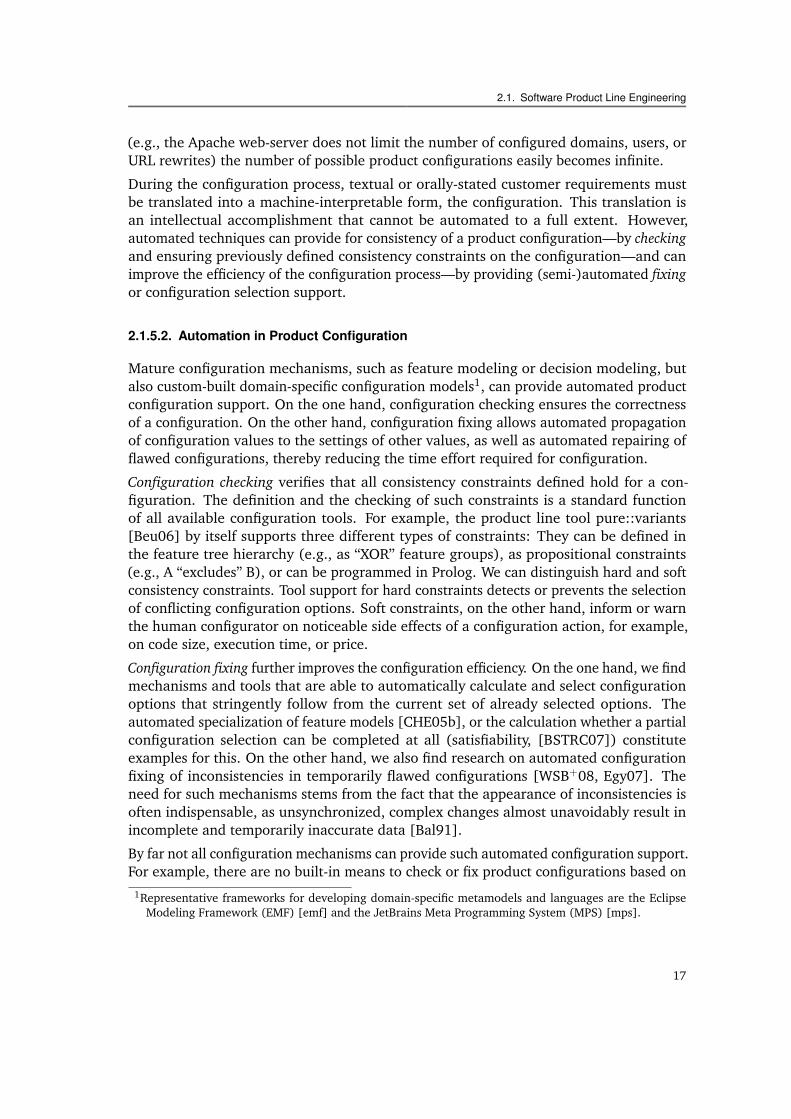
This section has provided a background on product line engineering, in particular, onproduct derivation automation and multi–product-lines. In a nutshell, product derivationautomation comprises configuration automation (configuration checking and fixing) andgeneration automation (management of build tasks) (cf. Figure 2.2). A comprehensivederivation automation approach must include all those elements. Multi–product-lines,in turn, increase the difficulty of automated product derivation. The different origins of
19
2. Background, Problem Analysis, and Introduction of Example Product Lines
Configuration Checking Configuration Fixing Build Task Dependency and Execution Management
Example:Pure::variants consistency checker
Example:Pure::variants autoresolver
Example:GNU make
Figure 2.2.: The essential ingredients of product derivation automation.
their sub–product-lines make integration of their product configuration and generationfacilities more challenging.
The characteristics hampering product derivation automation in multi–product-linesalready appear in regular product lines. The remainder of this chapter is dedicatedto two crucial challenges of product line engineering practice: the heterogeneity ofderivation mechanisms and stages in the derivation process. Each of the two followingsections will therefore first introduce an example product line revealing the correspondingcharacteristic, then provide a more detailed problem analysis, and, finally, state theconcrete challenges issued to product derivation automation.
2.2. Heterogeneity of Derivation Mechanisms
Various derivation mechanisms, this is, configuration and generation mechanisms, havebeen proposed and are being used in product line engineering. Configuration mechanismsrange from #define-based configuration to feature models, generation mechanisms fromgeneral-purpose compilers to specifically implemented domain-specific model transforma-tions.
This section provides evidence and reasons that these different derivation mechanismsdo not simply coexist peacefully, in separate, independent product lines. Already singleproduct lines often comprise a variety of different derivation mechanisms—which is evenmore the case for multi–product-lines. Homogeneity, in particular the homogeneity ofone single configuration mechanism, cannot simply be presupposed upfront. This has theconsequence that product derivation approaches must provide means to deal with thisheterogeneity, in order to provide for automated configuration.
Using an inductive approach, this section will first introduce the heterogeneous multi–product-line I4Copter. Based on its internals and further evidence from product lineresearch, the characteristics, the roots, and the relevance of heterogeneity will be analyzed.
20
2.2. Heterogeneity of Derivation Mechanisms
I4Copter
PXROSCiAO
CopterSwHw
DSLXML FM
CPP CPP
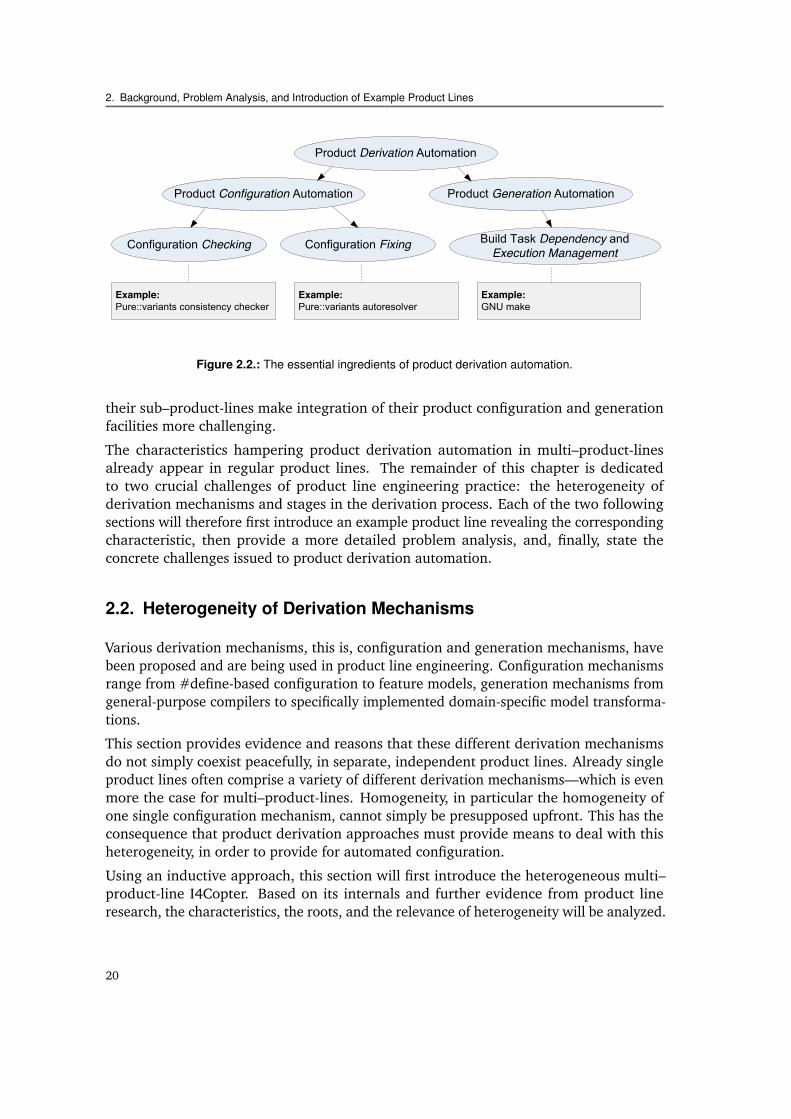
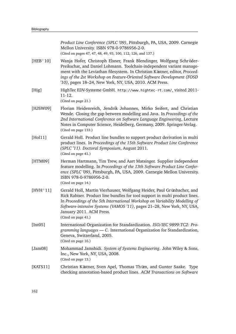
Figure 2.3.: The heterogeneity of configuration mechanisms of the I4Copter. The multi–product-line consistsof three sub–product-lines: CopterSwHw, PXROS, and CiAO. They are configured via C headerfiles with #defines (CPP), an XML-based language (XML), a feature model (FM), and a textualdomain-specific language (DSL).
Finally, the Heterogeneity Challenge is formulated, which states that automated productderivation approaches must provide means to deal with heterogeneity.
2.2.1. I4Copter: A Heterogeneous Multi–Product-Line
The I4Copter [UKH+11] quadrotor helicopter is a heterogeneous multi–product-line andconstitutes the first validation platform of this thesis. A quadrotor helicopter is a micro airvehicle that has vertical take-off and landing capabilities and that is controlled by varyingthe rotation speed of four fixed-pitch propellers. The I4Copter platform has been designedand developed to resemble embedded real-time systems in industry. The modular, openarchitecture of the platform makes it adaptable to various kinds of research and educationprojects that target challenges in real-time and embedded systems, distributed systems,robotics and cybernetics [UKH+11]. At the same time, the flexibility of its platform makesthe I4Copter an excellent example for the implementation of a heterogeneous productline that serves as a suitable validation subject.
The I4Copter is implemented as a multi–product-line. It integrates three other softwareproduct lines that are highly configurable and can be obtained and used separately.These are (cf. Figure 2.3): one product line for application logic, which also models theinterface to the hardware (CopterSwHw), the commercial operating system product linePXROS [Hig], and, as an alternative, the aspect-oriented CiAO operating system productline [LHSP+09].
The CopterSwHw product line is implemented in C++ and comprises approximately20.000 lines of code (LOC) [UKH+11]. Various software features are optional andalternative (approximately 50 configuration options in total). There are several hardwarevariants of the I4Copter, comprising different frames, sensors, and actuators, so that
21
2. Background, Problem Analysis, and Introduction of Example Product Lines
the hardware as well forms a product line. The software depends on information aboutthe available hardware components (approximately 60 configuration options). Both thesoftware part and the available hardware components of the CopterSwHw product line areconfigured via C preprocessor directives (#defines).
The application logic may run either on the operating system product line PXROS or onCiAO. PXROS is a commercial-grade operating system for hard real-time systems and hasbeen applied in domains ranging from communications technology to factory automationand safety-critical applications (SIL-4). For configuration of PXROS (tasks and otheroperating system parameters), a textual domain-specific language (DSL) is used. Asource code generator takes the domain-specific configuration file as input to create thecorresponding C start-up code.
The operating system product line CiAO, in turn, is much more versatile. It has beendeveloped using the principles of aspect-aware operating system development [LHSPS11],so that even fundamental architectural properties are configurable. It uses pure::variants[Beu06] feature models for configuration of its over 350 features that are implemented,including drivers, in approximately 21.000 LOC in C++. In order to specify and instantiatetasks, it uses an own XML dialect, defined in XML Schema [WWWC11]. Similar to PXROS,a source code generator takes such an XML configuration file as input to create thecorresponding C++ start up code for instantiation of tasks.
The heterogeneity of configuration mechanisms in the I4Copter product line has theimmediate effect that it becomes impossible to check for the validity of a configuration,as each automated configuration checking technique (as described in Section 2.1.5) onlyis able to deal with one particular homogeneous configuration mechanism. However,constraints exist across configuration mechanism boundaries. The exclusion of a featurein a feature model configuration of CiAO makes certain XML task attributes becomeunusable, whereas a C preprocessor #define of CopterSwHw in some cases requires afeature to be set. Similar dependencies exist from and to the DSL-based configuration fileof the PXROS product line.
In case these dependencies are not checked, configuration errors are likely to be introduced.As they can neither be detected nor corrected on configuration level, only subsequentcompiling and testing may be used to trace back possible configuration errors. Thisincreases development cost. However, no guarantees can be provided that configurationerrors, in particular when they only happen sporadically, are detected through testing. Inthe worst case, errors may not manifest as failures until hand-over to the customer, withpossibly fatal consequences at the customer site.
Due to the complexity of the I4Copter configuration facilities, it is a suitable subject toanalyze the characteristics and roots of heterogeneity. This will be done in the followingsection, which will also answer the more fundamental question: Is heterogeneity a raresymptom of bad design and can it be avoided, or is it an inherent phenomenon, whichcan hardly be prevented upfront?
22
2.2. Heterogeneity of Derivation Mechanisms
2.2.2. The Roots of Heterogeneous Derivation Mechanisms
In the following, the I4Copter will serve as illustrative example to fathom the roots ofheterogeneous derivation mechanisms in larger-scale software product lines. In additionto that, questionnaires, case studies, and experience reports will provide further evidence.
The I4Copter illustrates three reasons that increase the likeliness of heterogeneity: differ-ent binding times, different needs of variability representation, and multi–product-lines.
Different Binding Times. One indicator for multiple different derivation mechanismsis that most product lines have multiple different variability binding times. Thebinding time of a configuration option is the point in time when the option becomesmanifest in an actual product artifact, such as in the source code, in an object file, orin the running system (cf. [KCH+90], or [SJ04b]). Common binding times, at whichthe configured options are “transfered” into—or bound to—the software product,are source code generation time, compilation time, installation time, or softwarestartup time.
I4Copter Example. The I4Copter reveals different binding times. Some amount ofvariability is bound at source code generation time, via generators that take XMLand DSL files as input. Another part of the variability is bound at compilation timevia aspect weaving and configured via feature models. Finally, some of the compiletime configuration options are bound via the C preprocessor, which takes as input#define preprocessor variables defined in C header files. Note that, in contrast tomany other product lines, the I4Copter does not have any installation, startup, orruntime variability. This is a highly desired property in safety-critical systems, asit reduces runtime complexity in order to guarantee worst case execution times,whereas the implementation of specifically tailored measures for robustness (e.g.,parameter checks, or watchdog functionality) becomes possible.
Further Evidence and Reasons. Studies provide further evidence that differentbinding times are a rather common characteristic of industrial product lines. Chasteket al. [CDM04] performed a study on product derivation in industrial softwareproduct lines. Their questionnaire was distributed to stakeholders from domainssuch as medical, automotive, and telecommunication.2 Whereas the vast majority(over 90 percent) resolved some amount of variability at design time, by using plainimplementation mechanisms, half of them also used program generators of somekind to build parts of the products. Moreover, most participants (over 85 percent)bound variability at compile time, while still half of all respondents resolve variationat install and run time. In total, 50 percent of all respondents resolved variability atall four points: design, compile, install, and run time.3
2In total, the authors received 22 questionnaires in response.3Whereas the number of study participants is too small to provide representative data, the fact that the vast
majority of the investigated product lines actually has multiple binding times still constitutes an indicatorof the relevance of this topic during industrial product derivation.
23
2. Background, Problem Analysis, and Introduction of Example Product Lines
Deelstra et al. [DSB05], in turn, performed a case study on three industrial prod-uct lines. Each of the three product lines studied comprises at least two of thefollowing mechanisms: component composition, compile time variables, run-timeconfiguration variables.
Binding times indirectly indicate different derivation mechanisms. Only little re-search exists on derivation mechanisms for which binding times can be flexiblyadapted (e.g., [DFdJV03, SJ04b, SE08]). Commonly, at different binding times,different derivation mechanisms (both configuration and generation mechanisms)are used. In the I4Copter case, for example, source code generators are configuredvia XML and DSLs, whereas compile time variability is bound via feature modelingand CPP header files. Installation, startup, or run-time binding, in turn, usually is aswell configured differently, for example, via simple text files that assign values tocertain properties.
Different Representation Needs for Variability. Furthermore, the representation ofvariability is an issue. It needs to be tailored to the involved stakeholders andthe technical needs, both during domain and application engineering.
I4Copter Example. Interviews with the CopterSwHw developers revealed a strongdesire to “stick to the basics” of C preprocessor configuration when describing thevariability during domain engineering and when deriving products in applicationengineering. Due to their background in primarily code-centric development, theyhave been reluctant to introduce more advanced configuration techniques.4 Onthe other hand, the CiAO operating system has been designed from bottom up bydevelopers with profound product line background, so that feature models have beenused for describing configurative variability. However, some parts of the problemdomain were not suited for being described with feature models. The declarationand arbitrary instantiation of tasks is a concept that requires so called “structuralvariability” [VG07], which feature modeling cannot provide. In order to modelthis kind of variability during domain engineering, an additional, supplementaryXML-based language was developed.
Further Evidence and Reasons. Both the authors of [RGD10] and [ORRT09]identify that the presentation of variability to different application engineering stake-holders with their different backgrounds (customers, sales, developers, mechanicalengineers, administrators) in a suitable manner is an important research issue.As well, the participants in a survey of contemporary challenges from industrialpractitioners [CB10] mentioned that “the variability modeling approaches are notvery user friendly. How to document variability in a way that is easy to understandand use by different stakeholders is an issue.” However, it is not only the differentstakeholders that have an influence on the representation of variability. The par-ticipants in [CB10] affirm that different technical needs require different forms ofrepresentation: Variability is not always just a “bunch of numbers”—it might be
4This has only recently changed by introduction of the Kconfig language [SB10], known from the Linuxkernel, for configuration.
24
2.2. Heterogeneity of Derivation Mechanisms
the individually different system behavior (“a whole algorithm”) that represents avariability.
Domain-specific languages [MHS05] and modeling [KT08] have been developedto address the variability needs of the users reflecting their particular problemdomain more specifically. Usually more expressive than classical product linetechniques, such as feature modeling, they support instantiation and references ofconcepts and can be equipped with a syntax particularly suited to the knowledgeof the domain experts (e.g., mechanical or electrical engineers). Whereas thereare rather widespread domain-specific languages, such as SysML [Obj10b] andMatlab/Simulink in the embedded domain, or business process models (BPEL)[ftAoSISO07] in the enterprise area, it becomes more and more common to devisespecial-purpose languages for expressing the structural and behavioral variability ofindividual product lines (e.g., [BJMvH02, VG07, VV11]).
Composition to Multi–Product-Lines. Finally, larger-scale product lines are in numer-ous cases not developed from scratch as a single integrated platform. Assets arereused and composed from existing software components and product lines. Due tothe different origins of the constituent elements, there is a much higher likelihoodof different derivation mechanisms.
I4Copter Example. As already stated, the I4Copter constitutes a multi–product-line. It leverages the existing configurable operating system product lines PXROSand CiAO to build domain-specific functionality upon it (CopterSwHw). Due to thedifferent origins of its constituent elements (commercial vs. research, open vs. closedsource, operating system engineering vs. real-time system engineering), differentderivation mechanisms needed to be put together, resulting in a heterogeneousmulti–product-line.
Further Evidence and Reasons. In general, there is an increasing tendency towardsmore reuse and composition from existing software components and product lines[Bos10]. Reasons to do so are the widening of the portfolio of a product line[vOB02] or the enabling of distributed (“global”) software development or softwareecosystems [BBS10]. In particular, reuse of existing artifacts is crucial from aneconomical perspective. In order to keep development costs low, intra-organizationalreuse [Atk01], but also leveraging off-the-shelf or open source components [dJ09,vdLG06, vdLL07], is widely advocated for. As a result of integrating components orproduct lines from other departments, companies, or from open sources to multi–product-lines, the number of different derivation mechanisms increases, as eachcomposed element usually brings its very own means of handling variability.
Next to those arguments that can be illustrated via the I4Copter, there exist reasons forheterogeneity concerning the technical diversity of derivation mechanisms and that regardreports on the difficulty of derivation mechanism integration.
Technical Diversity of Derivation Mechanisms. Different derivation mechanisms notonly appear due to different binding times (e.g., code generation and compile time
25
2. Background, Problem Analysis, and Introduction of Example Product Lines
binding) or multi–product-lines. If considered beneficial, several derivation mech-anisms might be employed in a single product line at the same binding time. Forexample, solely during compile time, variability may be bound all via preprocessors,aspect-oriented programming, and via linking of different modules. This technicaldiversity increases even further when a product involves multiple different technolo-gies (e.g., a JavaScript-based browser client together with a C++- or Java-basedserver).
Reports on Difficulty of Technical Integration. In order to shield a configuring engi-neer from the heterogeneity of multiple different derivation mechanisms, productline approaches suggest to express all relevant product line variability in config-uration space models, such as feature models, define dependencies among theconfiguration entities, and generate other, lower-level configuration files out of theconfiguration model (as already mentioned in Section 2.1.5.2). This, however, wasconsidered difficult by several practitioners.
In the case studies of Deelstra et al. [DSB05], expert knowledge on derivationdependencies turned out to be difficult to document and maintain in a technicalmanner. It was perceived as expensive, an add-on of day-to-day derivation business,and difficult to formalize. Furthermore, the high upfront investment into the toolinginfrastructure and training of personnel to enable the modeling of configurationsand dependencies in an integrated, variability-mechanism–spanning manner wasconsidered as an obstacle.
A survey on the most common research issues in product derivation research byRabiser et al. [RGD10] indicates as well that one general, integrated variabilityapproach with automated product derivation support is difficult to achieve in prac-tice. This can be interpreted as a symptom of heterogeneity. Among the challengesmentioned most often by the survey participants were the “weak process integrationand tool interoperability” and the “low degree of automation”. As in this thesis,the term automation refers to both automatic product generation and to provid-ing configuration support when stakeholders take decisions. Similarly, O’Leary etal. [ORRT09] report on two independent research projects on product derivation.Both projects identify the lack of process and tool integration as one of the mainissues in product derivation.
The technical multitude of derivation mechanisms and the reported difficulty of theirconsolidation provide further evidence that heterogeneity is a widespread, highly relevant,and currently not sufficiently tackled issue. In particular when software is complex andinvolves multiple stakeholders and technologies, the presence of heterogeneous derivationmechanisms in a software product line must be considered as a “natural” phenomenon. Itis not the inherent result of a badly designed system that can simply be avoided upfront.
The negative consequences of heterogeneous derivation mechanisms primarily concern themultitude of configuration mechanisms. Having various different generator mechanisms,such as, various kinds of code generators, or different preprocessors and compilers, is notan immediate problem. Common build tooling (ant, make, etc.), as well as product line
26
2.3. Staged Derivation Processes
tooling (DOPLER, pure::variants) can be extended to invoke build tasks of diverse nature.Having multiple different configuration mechanisms, in contrast, results in a severedrawback: The configuration space becomes cluttered. Automated product configurationtechniques have no means to deal with this heterogeneity—the configuration checking andfixing techniques presented in Section 2.1.5 cannot be applied anymore. Configurationerrors that span the different mechanisms can neither be detected nor corrected, so thaterrors propagate into the product, and can only be resolved later on—with possibly drasticconsequences on development cost and product quality.
2.2.3. The Heterogeneity Challenge
The classical configuration automation approaches for checking and fixing configurations,as described in Section 2.1.5, cannot deal with heterogeneous product lines, that is,product lines that comprise a multitude of different derivation mechanisms. Evidence andreasons have been provided that numerous product lines in industry actually are of sucha heterogeneous nature. In particular, this is true for multi–product-lines, of which theconstituent elements come from various different contexts.
Therefore, each product line approach that claims to provide automated product derivationfor realistic legacy product line settings must answer the following challenge:
The Heterogeneity Challenge: In order to facilitate automated product configuration,this is automated configuration checking and fixing, a product derivation approachmust handle product lines that use a variety of different, “heterogeneous” derivationmechanisms.
The Heterogeneity Challenge constitutes the first challenge that will guide throughout theremainder of this thesis. Existing product derivation approaches will be evaluated in howfar they are able to address it. Their shortcomings will serve as an input to propose a new,improved product derivation approach that is free of their conceptual weaknesses. In thefollowing section, the second big challenge of this thesis, the Staging Challenge, will bederived.
2.3. Staged Derivation Processes
This section identifies and analyzes the challenges when the product derivation process issplit up into dedicated stages, as initially proposed by Czarnecki et al. [CHE05b]. First,the staged and heterogeneous multi–product-line SafeHome is introduced in order toillustrate concrete staging challenges. Then, an analysis of the staged product derivationprocess will be provided. It reveals that comprehensive automation must not regardconfiguration stages as mere black boxes; the stakeholders and build tasks within eachstage need to be considered as well in order to provide specifically tailored, automatedsupport. Finally, the individual challenges are subsumed under the Staging Challenge,
27
2. Background, Problem Analysis, and Introduction of Example Product Lines
SafeHome
SafetyPLiCSmartHome
FM
OSGi Prop
DSM FM
AntProp
DSM
Figure 2.4.: The heterogeneity of configuration mechanisms of SafeHome. The multi–product-line consistsof two sub–product-lines: SmartHome and SafetyPLiC. These are configured via feature models(FMs), domain-specific models (DSMs), and property value files for OSGi (OSGi Prop) and for antbuild scripts (Ant Prop).
which any comprehensive approach that aims at process support for staged derivationneeds to address.
2.3.1. SafeHome: A Staged Multi–Product-Line
SafeHome [ESSPL10] is a staged and heterogeneous multi–product-line and constitutesthe second validation platform of this thesis. It bases on the demonstrator product lineSmartHome [VG07, EFG+08], which has been developed for construction experts suchas architects and interior designers. SmartHome enables construction experts to modela building and its electrical interior devices. The models serve as input to generate thesoftware for automatically controlling the building’s devices. SafeHome constitutes anextension to SmartHome. It incorporates additional safety features, such as triple modularredundancy devices and error monitoring. The safety extensions have been implementedseparately from the base product line SmartHome. Doing so, the extension constitutesa separate (yet dependent) sub–product-line, called SafetyPLiC, which can be includedinto the build process of SmartHome if the customer is willing to pay for it. Figure 2.4illustrates the structure of the SafeHome product line and its configuration mechanisms.
2.3.1.1. Heterogeneous Derivation Mechanisms in SafeHome
SmartHome has been created in the context of the research project AMPLE [amp]. Itis based on the model-driven framework openArchitectureWare (oAW) [oaw], whichbuilds upon the Eclipse Modeling Framework (EMF) [emf]. It consists of hand-craftedJava of 6.000 LOC and model transformations, code generators, and modeling workflows(languages oAW Xtend, Xpand, MWE workflow language) of 3.300 LOC. The constructivevariability of the product line for modeling the rooms, windows, heating, lamps, and
28
2.3. Staged Derivation Processes
switches of a house is bound via domain-specific models (DSMs) based on EMF meta-models (70 classes and attributes in total). The configurative variability, this is, globaloptions, such as air conditioning, temperature management, or security, is configured viaa pure::variants feature model with 38 features and attributes. The startup variability ofthe used OSGi framework Knopflerfish [kno] is bound via a simple, property-value–basedconfiguration file (format: <property>=<value>). The Knopflerfish framework supportshundreds of configuration variables, of which around 40 are in actual use, such as, for thetelnet remote console, the http front-end, or the log level.
The SafetyPLiC extension has been implemented as a separate sub–product-line to eval-uate separation of concerns at the extent of an entire product line [ESSPL10]. It addsfunctionality for enabling devices for triple modular redundancy and for error injectionand monitoring. When applied to SmartHome, it adds further Java code, model transfor-mations and code generators of approximately 1.150 LOC into its build process. Similar tothe SmartHome case, constructive variability is bound via an additional, domain-specificsafety model (based on an EMF metamodel, 20 classes and attributes in total). The globaloptions, in turn, reside in an additional pure::variants feature model for safety (5 featuresand attributes). Finally, the variability of the Apache ant build task that triggers the triplemodular redundancy model transformation is controlled via a textual configuration file,which is also property-value–based (format: <property>=<value>). The interestedreader may find details on the internal implementation of the SafetyPLiC in [ESSPL10].
As can be seen, the SafeHome product line, just as the I4Copter product line, constitutes aheterogeneous multi–product-line. As well, the reasons for its heterogeneity go in linewith the evidence and reasons provided in the previous Section 2.2.2.
• First, there were different needs for the representation of variability in SmartHome.Global options of the product line are configured via a pure::variants feature model.Feature models, however, have a fixed syntax and are not well suited to model struc-tural variability, which is needed to express arbitrary instantiation and referencingbetween configuration elements. Therefore, an additional domain-specific housemodeling language has been devised to describe the concepts and interrelations ofhouse elements and interior devices [VG07].
• Furthermore, different binding times result in heterogeneity within SmartHome.Whereas the domain-specific house configuration models serve as input for codegeneration, the feature model configuration controls both code generation andcompilation, as well as the linking of further AspectJ [KHH+01] aspects into thecompiled binaries. Startup variability, in turn, is bound via a property-value–basedOSGi configuration file.
• Finally, SafeHome is a multi–product-line consisting of SmartHome and the Safe-tyPLiC. However, as the SafetyPLiC has been developed with the intention to beapplied to SmartHome, no artificial complexity is added. This is why the SafetyPLiCas well uses pure::variants feature models for global configuration options and anEMF domain-specific model to describe the safety characteristics of certain partsof the house. However, in order to tailor the ant build task that controls the triple
29
2. Background, Problem Analysis, and Introduction of Example Product Lines
modular redundancy model transformation for safety to specific needs, an additional,property-value–based configuration file was added.
2.3.1.2. The Staged Derivation Process of SafeHome
In addition to its heterogeneity, SafeHome will be used to illustrate the challenges andsolutions for staged derivation throughout this thesis. For this purpose, a staged derivationprocess has been devised for SafeHome. As the product line has been developed as aresearch demonstrator, it has no dedicated business or marketing concept. Therefore, itsderivation stages related to marketing and sales are derived from industrial experienceof the author [RHE+10]. Later derivation stages follow the characteristics of the houseautomation software and its actual derivation mechanisms. As the stages required forderiving a SmartHome and a SafeHome are mostly similar, primarily the SmartHomederivation process will be described in the following. Only the differences will be pointedout at the appropriate locations.
The derivation process comprises four configuration stages: initial contact, contractnegotiation, development, and setup. In each of the stages, one or several STAKEHOLDERS,adapt configuration files in order to execute build tasks. Figure 2.5 provides an overview ofthe process.
In the following, each of the four stages is shortly characterized:
SmartHome Stage 1: Initial Contact. During initial contact, the SALES ARCHITECT, or,in more complex cases, the SENIOR ARCHITECT, consults the customer and adaptsthe feature model configuration according to his or her wishes. Three build tasks—generate offer document, generate commercial conditions document, and calculate return-on-invest (ROI) of energy saving feature—take the feature model configuration as inputto create product-related artifacts. Each build task requires a distinct set of featuresto be set for proper execution.
SmartHome Stage 2: Contract Negotiation. During contract negotiation, the SALES
ARCHITECT or the SENIOR ARCHITECT, refine the feature model configuration and ini-tially create the domain-specific house model according to customer data. Exemplarybuild tasks are create 3D simulation and generate contract document.
SmartHome Stage 3: Development. During development, the DEVELOPER refines thefeature model configuration and the domain-specific house model. Various build tasksrelated to development (model transformations, code generation, compilation, testing)need to be executed.
SmartHome Stage 4: Setup. In the final setup stage, an administrator installs the de-vices at customer site, sets up the OSGi configuration file, and starts the homeautomation software.
Using the staged process of SmartHome, three challenges of comprehensive staged config-uration support can be illustrated: basic staged derivation support, build task integration,and stakeholder guidance.
30
2.3. Staged Derivation Processes
Prod
uct
Part
sSt
ages
Bui
ld T
asks
Con
fig.
File
sSt
akeh
olde
r
Initial Contact
Sales Architect Senior Architect
Contract Negotiation
Developer Administrator
Development
Gen
erat
e O
ffer
Doc
uman
t
FM OSGi Prop
DSM
Setup
Gen
erat
e C
omm
erci
al
Con
ditio
ns D
ocum
ent
Cal
cula
te E
nerg
y S
avin
g Fe
atur
e R
OI
Cre
ate
3D S
imul
atio
n
Gen
erat
e C
ontra
ct
Doc
umen
t
Mod
el T
rans
form
atio
n
Com
pila
tion
Cod
e G
ener
atio
n
Sta
rtup
Figure 2.5.: An overview of the staged derivation process of SmartHome. It involves several stages, atwhich stakeholders create or adapt different configuration files in order to execute build tasks thatproduce product parts.
• Example Challenge 1: Basic Staged Derivation Support. Certain feature attributes,such as the customer name attribute, must be set in order to finish the initial contactstage. Basic staged derivation support must check, during each stage, whether alldata has been gathered and is consistent in order to proceed to the next stage.
• Example Challenge 2: Build Task Integration. Build tasks should be integratedinto the staged derivation process. For example, the build task for calculatingthe ROI of the energy saving feature in the initial contact stage is optional. Itsexecution is not necessary in order to proceed to the next stage. The build taskrequires that the attribute “number of permanent inhabitants” is set in the featuremodel configuration. A respective consistency check must depend on the buildtask—an error message reporting that the attribute is not correctly set should onlybe displayed if the customer actually desires the calculation to be made. Build-task–specific consistency checks are needed.
The build tasks for generating the offer and the commercial conditions documents,in turn, are mandatory during initial contact. A tool should enforce their execution.
31
2. Background, Problem Analysis, and Introduction of Example Product Lines
It must be secured that all required build tasks are executed in order to proceed tothe next stage. If a build task depends on others, all dependent build tasks needto be executed as well, in the correct order. Build-task dependency and executionmanagement is required.
• Example Challenge 3: Stakeholder Guidance. Finally, the involved stakeholdersshould receive detailed warnings or should even be actively hindered from perform-ing certain actions, depending on their stakeholder role. During initial contact, onlythe feature model configuration must be edited; warnings should be displayed whenthe domain-specific house model is going to be edited. The sales engineer, in turn,should receive detailed configuration hints when selecting certain features. Theexperienced senior architect, in contrast, shall not be obstructed by such detailedguidance.
During contract negotiation stage, both the senior and the sales architect may editthe feature model configuration and the domain-specific model. Due to lackingknowledge, however, the sales architect must not edit any features or model elementsthat relate to security. After handover to the developer, neither sales nor seniorarchitect may continue editing the feature model configuration or the domain-specific house model, in order to avoid desynchronization.
Basic staged derivation support, build task integration, and stakeholder guidance willbe analyzed more thoroughly in the following section. Before that, the requirementsfor staged derivation in multi–product-lines will be illustrated with a further example ofSafeHome, which combines SmartHome with the SafetyPLiC.
In order to develop a SafeHome product, each stage of the SmartHome product lineneeds to be refined with regard to the SafetyPLiC. This makes SafeHome a staged multi–product-line. The SafetyPLiC has four configuration stages as well, similar to those ofthe SmartHome product line. The first stage—the safety initial contact stage—-must notstart until SmartHome’s initial contact stage is completed. The other three SafetyPLiCstages—safety contract negotiation, safety development, and safety setup—run in parallelto the corresponding stages of SmartHome. Each of the SafetyPLiC’s stages contributesfurther configuration files, build tasks, stakeholder roles, and relations among thoseentities.
In the following, SafeHome’s development stage, which is composed of SmartHome’s andthe SafetyPLiC’s development stage, is described as one example:
SafeHome Stage 3: Development. During the SafeHome development stage, the DEVEL-OPER refines the feature model configuration and the domain-specific house model ofSmartHome. The SAFETY DEVELOPER (possibly the same person as the DEVELOPER),refines the SafetyPLiC’s safety feature model configuration, the safety domain-specifichouse model, and the ant property file for configuration of safety-related buildtasks. Both SmartHome and the SafetyPLiC comprise model transformations and codegenerators, which need to be executed in the right order for building products.
32
2.3. Staged Derivation Processes
The composition of staged derivation processes for multi–product-lines adds a fourthchallenge to the list:
• Example Challenge 4: Composition of staged derivation processes. All challengesmentioned before—basic staged derivation support, build task integration, andstakeholder guidance—must support multi–product-lines. For example, build taskdependency and execution management must ensure that the model transformationsand code generators of the two product lines SmartHome and SafetyPLiC arecorrectly configured and executed in a particular order as, otherwise, erroneoussource code will be generated.
The four example challenges illustrate that, for a comprehensive automated stagedderivation approach, basic staged configuration support is not nearly sufficient. To solvethis, build tasks, the configuration stakeholders, and multi–product-lines need to be takeninto account in addition.
The following section will provide a more thorough analysis of staged derivation. Itprovides further arguments and evidence underpinning that stakeholders and buildtasks are crucial elements in the staged derivation process, which explicitly need to beconsidered.
2.3.2. An Analysis of Staged Derivation
Originally introduced by Czarnecki et al., “staged configuration” denotes the case that “theprocess of specifying a family member . . . (is) . . . performed in stages, where each stageeliminates some configuration choices” [CHE05b]. In line with the terminology of Czar-necki et al., the main entity of the derivation process will be called “configuration stage”.Stages are product line specific and can range, for example, from first customer contactand contract negotiation, over platform derivation and product-specific development, toinstallation and startup of the product at customer site.
This thesis explicitly considers two aspects of product derivation: product configurationand product generation (cf. Section 2.1.5). To highlight this fact, the staged process asa whole will be referred to as “staged derivation” (as opposed to staged configuration,as defined in [CHE05b]). This emphasizes that not only configuration, but also productgeneration needs to be considered for fully-fledged automation support.
Accordingly, the following sections analyze staged derivation from two view points.The first adopts a configuration-oriented perspective, as also done by Czarnecki etal. [CHE05b]. It will reveal that individual stakeholder guidance is an important, al-though currently neglected issue in staged derivation. The second section addressesthe impact of product generation on the staged derivation process and highlights theimportance of build task integration.
33
2. Background, Problem Analysis, and Introduction of Example Product Lines
2.3.2.1. The Impact of Configuration on Staged Derivation
After a brief discussion of the configuration stage dimensions of Czarnecki et al. [CHE05b],this section proposes its own classification in order to decouple the identified elementsmore strictly. Based on the analysis, the staging challenges with regard to productconfiguration can be formulated: basic staged derivation support and individual stakeholderguidance.
Czarnecki et al. propose a classification of configuration stages along three “dimensions”:time (stages induced by the lifecycle phase, such as, development, roll-out, deployment),target (stages induced by the system to be configured, such as, component type config-uration, component instance configuration), and role (stages induced by the differentconfiguration stakeholder roles involved). The authors, however, do not analyze the inter-relations of the three dimensions any further. Whereas the term “dimension” indicatesorthogonality, the proposed solution of Czarnecki et al., “multi-level feature models”,cannot support multiple dimensions. As will be shown subsequently in Section 3.3.1, it isonly capable of modeling one linear sequence of stages, which supports only one singledimension at a time.
The following classification intends to decouple the involved entities, so that a morethorough analysis of the concepts becomes possible. Furthermore, configuration optionsreceive a more prominent role in the classification. Stated in a different way, a stagedconfiguration concept should answer the question “when” (at which lifecycle or target-specific configuration stage) “what” (which configuration option) may be configured “how”(to which configuration values) by “whom” (by which stakeholder roles).
The “when” denotes the series of configuration stages to run through. These stagesneed to match the lifecycle phases of the product line, as well as its target-specificconfiguration needs. The stages may, for example, comprise initial customer contact,platform derivation, product-specific development, and installation. The “what” refersto the set of configuration options that need to be configured appropriately within astage. Note that, in larger scale scenarios, configuration options will be spread overconfiguration files of multiple heterogeneous configuration mechanisms. So, in general,configuration files will be orthogonal to configuration stages—one single configurationfile may require successive adaptation at different configuration stages. Note that the“how”, the configuration checks that define to which values configuration options maybe set, is as well a dedicated dimension. This highlights the fact that configurationrestrictions can differ in separate stages, for example, more and more restrictions can beadded in each stage. Eventually, the “who”, which is the set of configuration stakeholdersinvolved, will also be orthogonal to the configuration stages. Different stakeholders (e.g.,salesmen, developers, administrators) may require individual process guidance: Theymay have different configuration permissions and restrictions and will require differentconfiguration hints depending on their experience at each of the stages.
Based on the four concepts of “when”, “what”, “how”, and “who”, the challenges forautomated staged derivation regarding the configuration process can be split up into basic
34
2.3. Staged Derivation Processes
staged derivation support and individual stakeholder guidance. On the one hand, it mustbe possible to define configuration checks and fixes (“how”) on configuration options(“what”), whereas the checks and fixes may be relative to the current configuration stage(“when”). This corresponds to basic staged configuration support in its classical sensedefined by Czarnecki in [CHE05b]. On the other hand, the different stakeholders (“who”)should receive stakeholder-individual process guidance in order to tailor their permissions,restrictions, and possible configuration hints to their experience.
Each approach for automating staged product configuration needs to evaluate its ca-pabilities with respect to these concepts. A fully-featured approach would enable fullorthogonality of all involved concepts: configuration options, checks and fixes, configura-tion, stages, and stakeholders. In Section 3.3.1, existing approaches and concepts will beanalyzed with respect to their capabilities to address basic staged derivation support andindividual stakeholder guidance.
2.3.2.2. The Impact of Generation on Staged Derivation
After having addressed the configuration aspect of the staged derivation process, thissection analyzes its impact on product generation.
As a starting point, we usually find that various different build tasks are involved ingenerating a product from a product configuration. They start from offer document andproduct description generators during initial contact, over model-transformations, codegeneration, aspect weaving, preprocessing, and compiling build tasks during development,to installer and initialization scripts during deployment and startup.
The individual build tasks are usually not wired together to a monolithic “generate-all”task. This is particularly true when different stages are involved—an offer documentgenerator is executed at a totally different time than a compilation build task or an installscript. Next to this relation of build tasks to stages, within each stage, partial execution ofbuild task sequences may be required. For example, when developing product-specificcode during product derivation, most of the time, the software is only partially built.Examples include: Only generating source code for static analysis, compiling only a singlecomponent in order to perform unit tests, or compiling the whole system for sandboxtesting, but without building of an installer package.
Such dependency and execution management for partial building is usually done via com-mon build tools, such as GNU make and Apache ant. Therefore, a comprehensive productline approach for automated, staged generation must reuse such tools or provide ownmeans to manage the execution of the various different build tasks in each stage. Fur-thermore, the relations between build tasks and stages need to be defined. One possiblerelation, for example, would be that the execution of a build task is mandatory in order tocomplete a stage.
When partial execution of build task sequences is supported, it should be checked whetherthe configuration is valid—with respect to the build tasks that actually shall be executed.
35
2. Background, Problem Analysis, and Introduction of Example Product Lines
For example, when only the build task for source code generation shall be executed todo a static analysis, it does not matter whether the configuration for the build tasks ofcompilation, linking, and packaging is valid. When the sandbox testing build task shallnot be executed, in turn, an inconsistent sandbox configuration should not be considereda configuration error. Therefore, to comprehensively support automated generation, aconcept is needed for build-task–specific consistency checks and fixes in order to assignchecks and fixes to specific build tasks.
To sum up: The integration of product generation into the concept of staged derivationcontributes further challenges. In order to support not only staged configuration, asprevious approaches, but also the actual generation of products artifacts, build taskintegration is needed. It comprises dependency and execution management for build tasksas well as a configuration automation concept that allows defining build-task–specificchecks and fixes.
The integration of build tasks into the staged derivation process fosters comprehensivederivation support and extends staged configuration to actual staged derivation. Ananalysis of the capabilities of current tools and approaches to address these challengeswill follow in Section 3.3.1.
2.3.3. The Staging Challenge
The previous sections have illustrated and analyzed a refined staged derivation concept,which allows stating its challenges more clearly. Subsuming them under one single notion,a comprehensive approach for automation of the derivation process in staged productlines needs to address the following challenge:
The Staging Challenge: To support the staged product derivation process, a productderivation approach must provide basic support for stages to answer the questionwhich configuration options may or must be set to which values at which stage.In order to provide more comprehensive process support, stakeholders shouldreceive individual process guidance, at each stage, according to their experience.Additionally, the product derivation process should integrate build tasks in orderto enable dependency and execution management of build tasks and allow forbuild-task–specific consistency checks and fixes at each of the stages.
The Staging Challenge, together with the Heterogeneity Challenge (cf. Section 2.2.3)will guide through the remainder of this thesis. Existing approaches will be evaluatedwith respect to these challenges. Their shortcomings will serve as an input to propose animproved product derivation approach that is free of their conceptual weaknesses.
2.4. Chapter Summary
This chapter provided a background on product line engineering with a particular focuson multi–product-lines and product derivation automation. The concepts of heterogeneity
36
2.4. Chapter Summary
and staged derivation were discussed, which lead to the identification of the HeterogeneityChallenge and the Staging Challenge for automating large-scale product derivation.
In a nutshell, the Heterogeneity Challenge requests that product derivation approachesneed to provide means to deal with legacy product lines that use various different con-figuration and generation mechanisms internally. The Staging Challenge, in turn, notonly demands that stages receive a first class representation during product derivation.All important participants of the derivation process, in particular the configuring stake-holders and the build tasks to be executed, need a proper representation. Finally, bothchallenges need to be approached in the context of multi–product-lines, in order to adaptto large-scale settings.
The I4Copter and the SafeHome example product lines were presented in order toillustrate the challenges of automated product derivation in staged and heterogeneousmulti–product-lines. The product lines will also serve as running examples and validationsubjects throughout this thesis.
37
3State of the Art
This chapter analyzes the state of the art in automated product derivation regardingmulti–product-lines, heterogeneity, and staged derivation. After a general outline ofprevious derivation approaches, with a particular focus on approaches supporting multi–product-lines, their handling of heterogeneity and staged derivation and their respectivedeficiencies are discussed. Based on these deficiencies, the requirements for an improvedautomated product derivation approach are identified.
3.1. Overview of Product Derivation Approaches
This section gives a general overview of tool-supported product derivation approachesand distinguished multi–product-line approaches.
3.1.1. Technical Product Derivation Approaches
This thesis targets technical product line approaches, with a particular focus on theirproduct derivation support. Approaches that focus solely on the methodological level,such as, the Product Line Software Engineering Method (PuLSE/PuLSE-I) [BFK+99,BGMW00], KobrA Component-Based Product Line Development [Atk01], the SEI ProductLine Practice Initiative [CN01], Product Line UML-Based Software Engineering (PLUS)[Gom04], and the Orthogonal Variability Modeling Approach (OVM) [PBvdL05]1, are notfurther considered.
1The VarMod-PRIME tool allows to model the variability of a product line using variation points and variants,but, at the time of writing, does not yet allow for describing concrete product instances or generatingproducts. VarMod-PRIME homepage: http://www.sse.uni-due.de/wms/de/?go=256, visited 2011-11-12.
Tool-supported product derivation approaches combine methodological support withautomated derivation mechanisms. Typically, each approach provides only one single,“homogeneous” configuration mechanism for automated configuration checking and fix-ing. A set of generator mechanisms is then provided to actually build products fromconfigurations.
The individual tool-supported derivation approaches base on multiple different configu-ration mechanisms for expressing variability: pure::variants [Beu06] and Gears [Kru07]use feature models, the DOPLER approach [RGD07] decision models, and COVAMOF[SDNB07] variation point and variant modeling. Koala product populations [vOvdLKM00,vO02] and the Com2 approach [PHSK07] (pronounced com square) use variability-awarecomponent architecture models. Kumbang and Koalish [AMS07, ASM03], in turn, modelvariability by combining feature modeling with a configuration domain ontology andKoala, respectively. Autobundle, finally, uses a string-based property value mechanism forconfiguration, as provided by the autoconf and automake tool suites [dJ05]. All productderivation approaches, except for autobundle, offer automated configuration supportvia configuration checking and fixing. Pure::variants, for example, uses a Prolog engine,DOPLER a rule engine, and COVAMOF an inference engine [SDH06] for this purpose.
The set of supported generation mechanisms differs among the approaches. Thosethat configure via architecture and component models [vO02, ASM03, AMS07, ASM03,PHSK07] restrict their generation mechanisms to composition and parameter settings forsoftware components. For product generation, they basically wire up the implementedcomponents according to the input configuration models. Additionally, the implementedcomponents need to follow strict rules. For Koala and the Com2 approach, for example, Cis the required implementation language, specific descriptor files need to be provided, andstrict naming conventions must hold. The build-system–centered approach autobundle, inturn, presupposes the use of the automake tool suite for product generation [dJ05]. Theother product line approaches, such as, pure::variants, Gears, DOPLER, and COVAMOV,do not restrict the possible generator mechanisms and provide extensible generatorframeworks for this purpose. Usually, they are already shipped with a set of predefinedbuild tasks, which take their configuration model as input to produce artifacts. Example forsuch build tasks include file copying, file preprocessing, or template-based text generators.In addition, these product lines tools provide an interface for implementing arbitraryadditional build tasks.
DOPLER and pure::variants have, as an additional feature, the capability to map therespective configuration model to an intermediate domain-specific model (called familymodel in pure::variants). This model is then fed into the product generators. Doing so,the generators are decoupled from the configuration model and can easier be reused.
As mentioned, one striking commonality of all product derivation approaches is thatthey determine a specific configuration mechanism to be used, for example, featuremodeling or component modeling. All 33 variability modeling approaches identifiedin a systematic literature survey by Chen et al. [CBA09] reveal this characteristic. Thisleads to the following question: How do the approaches adapt to legacy settings, where
40
3.1. Overview of Product Derivation Approaches
multiple different, heterogeneous configuration mechanisms are already in place? Forexample, in the I4Copter product line, we find domain-specific text files, C preprocessorvariables, XML files and feature models. Their strategies to address this will be discussedin Section 3.2.1. Before that, the following section will give a short outline of multi–product-line approaches.
3.1.2. Related Work on Multi–Product-Lines
Related work on multi–product-line roughly can be separated into two groups: workthat concentrates on domain engineering tasks, and work that also concerns automatedproduct derivation.
Dhungana et al. [DGRN10], for example, discuss different strategies how to structure themodeling space of large-scale product lines in domain engineering. Altintas et al. [AC08]propose to bundle the artifacts of each product line together with their development andexecution environments into so called domain-specific kits. This allows for managing andmeasuring the reuse across all assets related to the different product lines. In [BLP05],Bühne et al. propose an extension of the orthogonal variability model [PBvdL05] formulti–product-line modeling.
Set-theoretic approaches towards modeling multiple product lines in domain engineeringhave been proposed by Thompson et al. [TH01, TH03] and Parnas [Par08]. In bothapproaches, the product portfolio is partitioned in several sub-sets (sub–product-lines)based on the characteristics of the products (e.g., by hardware platform, display type,or programming language). Finally, Reiser et al. [RW06, RW07] present a frameworkfor decentralized evolution of multiple feature models and dependencies among them.Therefore, each feature model has assigned a reference feature model, which models its“public interface”. Modeling of dependencies is only allowed towards the reference featuremodels, so that stability of references can be assured.
All previously mentioned related work only concerns domain engineering and doesnot deal with technical derivation of products, which is the main topic of this thesis.Several product population approaches (as introduced in Section 2.1.3.2), provide forautomated derivation of products, in particular, Koala [vO02], the Com2 component model[PHSK07], and the build-level components approach [dJ05]. All these product populationapproaches have in common that they tightly limit the set of derivation mechanisms to use;in each case, the configuration mechanism (e.g., property-value–based), the generationmechanism (component-based composition), and the implementation style for the sourcecode (according to the component model) is fixed.
Holl et al. [HVH+11] propose to bundle the configuration models of each product linewith product-line–specific tooling, such as custom visualization, calculations, and productgenerator components. Delivering this tooling as an entire bundle to the stakeholderslowers the deployment effort in multi–product-line derivation scenarios. Additionaltooling that targets distributed configuration and configuration constraint mining andenforcement is currently being developed [Hol11].
41
3. State of the Art
Finally, further multi–product-line approaches base on feature modeling for productderivation. Rosenmüller et al. [RS10] use a combination of class and feature models,whereas Fries [Fri07] uses so called composition models together with feature modelsin order to derive products from multiple product lines. The Compositional VariabilityManagement (CVM) framework [APS+10], finally, extends the feature-model–basedapproach of Reiser et al. [RW06, RW07] for product derivation.
All mentioned product derivation approaches for multi–product-lines, similar to those forcommon product line engineering presented in the previous section, are homogeneous—they do not tackle explicitly how to integrate different heterogeneous derivation mecha-nisms.
3.2. State of the Art in Heterogeneity and Its Deficiencies
This section analyzes the state of the art in heterogeneous product derivation automation.Two strategies are used, which both base on reengineering the product line to a singlehomogeneous configuration mechanism. After describing the strategies, their fundamentaldeficiencies will be shown. Various technical and business reasons hinder their applicability,rendering the automation of product derivation impossible for many practical cases.
3.2.1. Previous Strategies to Address Configuration Heterogeneity
All derivation automation approaches described in the previous section are only configuredvia one single, homogeneous configuration mechanism, such as feature modeling. TheHeterogeneity Challenge (cf. Section 2.2.3), however, requires the ability to deal with avariety of different configuration mechanisms. In order to enable the entire product linefor automated product derivation, previous approaches must transform the product lineto a homogeneous one. This includes all configuration options of the product line, fromsource code generation to startup configuration switches. Basically, two strategies may beapplied: the invasive strategy or the further layer strategy.
Invasive Strategy. For applying the invasive strategy, all configuration options needto be ported from their legacy configuration mechanisms to the one mechanismnatively supported by the derivation tool (e.g., feature models). As a consequence,also the generator mechanisms, such as code-generator templates and preprocessors,need to be replaced. For example, XSLT constitutes the generation mechanismnaturally supported by pure::variants to create textual files according to featuremodel configurations. Similarly, Gears provides its own language for annotatingcode for preprocessing, similar, yet distinct from the C preprocessor. A purely inva-sive approach needs to completely replace all legacy configuration and generationmechanisms with the ones the desired derivation tool naturally supports.
Further Layer Strategy. The further layer strategy, in turn, allows for keeping the al-ready existing derivation mechanisms in place. In order to homogenize the configu-
42
3.2. State of the Art in Heterogeneity and Its Deficiencies
ration, the existing variability, however, must be re-modeled using the configurationmechanism of the desired product line tool (e.g., feature modeling). Then, gen-erators need to be developed that map from this configuration mechanism to thelegacy configuration mechanisms (e.g., from the feature model to header files with Cpreprocessor variables).2 The further layer strategy prevents major invasive changesto the product line—at the cost of adding a further layer of configuration modelsand generators.
To sum up: The invasive and the further layer strategy are the two valid options for intro-ducing automated product derivation to product lines with heterogeneous configurationmechanisms. Both require some form of reengineering—either by invasively replacingall legacy configuration and generation mechanisms or by re-modeling all configurationoptions on a further layer and developing generators for the mapping to legacy configura-tion files. The following section will show that both strategies have deficiencies for manysettings highly relevant in industrial practice.
3.2.2. Deficiencies of Previous Approaches Regarding Heterogeneity
Before reengineering a legacy product line to one single homogeneous configurationmechanism, practical considerations must be taken into account. In fact, the invasive andfurther layer strategies are far from generally applicable, what renders comprehensiveautomation in many cases impractical, infeasible, or virtually impossible. The needs ofthe stakeholders, the complexity of the problem domain, and business considerations arereasons to doubt that one single configuration mechanism can be a generally applicablesolution for industrial-scale product lines:
1. The “one configuration mechanism fits all” approach ignores stakeholder needsand practices. Several surveys and experience reports state that the appropriate-ness of a configuration mechanism to the configuring stakeholders is a crucial issuein product line engineering [RGD10, ORRT09, CB10]. Choosing one dedicatedconfiguration mechanism as the one and only, however, directly opposes the aimto meet the individual needs of the different stakeholders involved in the configu-ration of a product line. On the contrary, as stakeholder needs are different, theconclusion may be drawn that there plainly is no general, one-fits-all configurationmechanism: The appropriateness of a configuration language depends on its users!Different stakeholders “think different” and therefore prefer different languages.While business-oriented people often favor configuration via visual or spreadsheet-like languages [RHE+10], embedded software developers can be reluctant to usevisual configuration languages and are often fine with classical, text-based config-uration practices that are as close as possible to the program source code, such
2This strategy is also proposed in an illustrative example provided by the pure::variants vendors. Pure-systems homepage:http://www.pure-systems.com/downloads/flash/pv-spl-10min/flash.html, visited 2011-11-12.
as C preprocessor defines. Electrical engineers, finally, may rather prefer visualconfiguration languages similar to block diagrams.
2. Different problem domains demand different expressiveness. Compared todomain-specific languages [MHS05] and modeling [KT08], the expressiveness ofclassical product line variability modeling languages, such as feature modeling,decision modeling, or component-based approaches, such as Koala and Com2, isvery limited. Commonly, they do not support arbitrary instantiation of concepts(called unbounded cardinalities in feature modeling [CHE05a]), a mechanism toreference other concepts (e.g., feature references), or inheritance. The structureof various configuration problems, however, requires not only “configurative”, butalso “constructive” [Völ09], or even behavioral [VV11] specification of a product.For example, in order to model the structure of a house with its floors, rooms,interior devices, and relationships among all these elements (such as in the Safe-Home example in Section 2.3.1), a custom-developed metamodel is much bettersuited than, for example, feature modeling. For configuring the behavior of webservice compositions, in turn, BPEL is as well much more appropriate. In general,different problem domains demand languages of different and specifically tailoredexpressiveness. Otherwise the language cannot cover the full complexity of theproblem.
3. Business or technical demands may impede reengineering. Even in cases wherea single configuration mechanism can be found for a product line that serves allstakeholder and expressiveness needs, altering the legacy mechanisms of each com-ponent is a considerable effort. The invasive strategy requires replacing the existingderivation mechanisms, whereas the further layer strategy demands building anew configuration mechanism on top of the existing one. Both may have consider-able drawbacks from a business perspective or may be virtually impossible due totechnical considerations.
Applying the invasive strategy may be hampered by the industrial demand to costefficiency. It fosters the reuse of legacy, commercial, and open-source components,or even the reuse of other product lines as constituents when developing a multi–product-line. However, replacing the internal derivation mechanisms of a componentto support configuration automation may be disapproved of due to high reengineer-ing cost. Furthermore, and more fundamentally, replacing derivation mechanismsof one such component is obviously only possible if its source code is available andmay be changed. For commercially purchased components, this is mostly not thecase. Finally, even if a reused component is open source, altering might not be anoption due to licensing or redistribution issues or because a privately managed forkof the code base would require costly merging in case of updates to the publiclyavailable fork.
In order to avoid invasive changing of commercial or open source components,one could apply the further layer strategy. This means re-modeling configurationoption of lower-level configuration files in higher-level configuration space models
44
3.3. State of the Art in Staged Derivation and Its Deficiencies
of one single mechanism and use generators to generate the latter out of theformer. Next to introducing a further layer of complexity, the decision whichconfiguration options to re-model is a tightrope walk: On the one side, the effort formirroring basically all configuration options from the lower configuration level onthe upper level—and for developing an appropriate generator to map from one tothe other—can be enormous. On the other hand, limiting the set to too few optionsis equally undesirable, especially when the customer strongly influences the productrequirements and can demand individually tailored “solutions” [ELSP09]. Thismeans that there is an immense amount of potential variability in the product line,and a reasonably limited subset cannot be determined in advance. This case is quitecommon in industry [DSB05]. Siemens AG, for example, attributes at least the sameimportance to the delivery of customer-tailored solutions as to the development ofprefabricated products.3
To sum up: There are various cases where the reengineering to one single configurationmechanism is impractical or impossible. Different stakeholders may demand differentconfiguration languages, the technical complexity may require high expressiveness toaddress the problem complexity, and business or technical demands may impede reengi-neering. However, all previous product derivation approaches require reengineering toa homogeneous configuration mechanisms. Basically, up to now, complete automatedproduct derivation is not possible in such settings.
What is missing is a light-weight approach that renders the integration of heterogeneousconfiguration mechanisms possible without laborious reengineering, and that is comprehen-sively applicable to a wide range of legacy mechanisms, from existing feature–model–basedconfiguration, over domain-specific models and languages, to fine tuning via #defines inC header files.
3.3. State of the Art in Staged Derivation and Its Deficiencies
We have seen that previous approaches fall short in numerous ways when the Heterogene-ity Challenge shall be addressed. In this section, it shall be shown that the same is true forthe Staging Challenge (cf. Section 2.3.3). First, an overview is given of previous stagedderivation approaches. Then, their fundamental deficiencies are highlighted.
3.3.1. Previous Approaches to Address the Staged Derivation Process
The Staging Challenge concerns the automation of the staged derivation process. Asa minimal requirement, it requires modeling of distinct configuration stages, in orderto describe which configuration option (“what”) may or must be set to which values(“how”) at which stage (“when”). Furthermore, stages should not merely be black boxes.
3Siemens Global Website – Strategy: http://www.siemens.com/about/en/values-vision-strategy/strategy.htm, visited 2011-11-12.
In order to provide more comprehensive derivation support, stakeholders should beexplicitly represented so that they can receive individual process guidance within eachstage, according to their experience. Additionally, the product derivation process shouldintegrate build tasks in order to enable build-task–specific consistency checks and allowfor dependency and execution management of build tasks.
This section gives an overview of how previous approaches have addressed the derivationprocess and how they deal with configuration stages, stakeholder process guidance, andbuild tasks. As will be shown, previous approaches only can provide basic derivationsupport. Advanced functionality that concerns stakeholders or build tasks is hardlyconsidered by any of the approaches.
3.3.1.1. Configuration Stages
Basic support of distinct configuration stages needs to model which configuration optionmay or must be set to which values at which stage. This section gives an overview ofexisting automated staged derivation approaches.
Nearly all existing automated concepts are limited to feature models as configurationmechanism. In particular, their solutions are based on the two related concepts Czarneckiet al. [CHE05b] proposed for the problem. The first is the “specialization” of featuremodels, which denotes the step-wise taking of each configuration choice separately. Thesecond concept is called “multi-level feature modeling”. In multi-level feature modeling,each stage or level is modeled in a separate feature model. As soon as one stage or level iscompletely configured, the feature model configuration at the lower level is preconfiguredaccording to the feature model configuration of the upper level. Then, the humanconfigurator continues to configure the configuration of the lower level. The authorsprovide a feature modeling tool that implements the concept. Also, the commercial toolpure::variants is able to support the approach, as it can deal with multiple feature modelsand can propagate configuration decisions.
Almost all further research on staged configuration is based on feature modeling. Most of italso is rooted in multi-level feature modeling. Classen et al. have developed a formalizationsemantics for multi-level feature modeling [CHH09], in order to point out and improveambiguous concepts of the original concept. The authors of [BBG+10] automate theconfiguration choices during specialization using semantic web reasoners. A formalizationof specialization that incorporates fuzzy logic for improving interactive configuration canbe found in [BNGR11]. In [WDSB09], constraint satisfaction programming is used toselect the order of specialization choices in order to optimize external constraints (suchas, the costs of selected features per year must not exceed one million dollar). Finally,Mendonca at al. [MCO07] extend basic feature modeling with the concept of decision sets.The set of features of a feature model is partitioned into such decision sets. Accordingto priorities attached to each decision set, and according to the configuration constraintsbetween the features, a partial order is calculated for the decision sets. This order then
46
3.3. State of the Art in Staged Derivation and Its Deficiencies
is mapped to a staged configuration process so that the sequence of stages is calculatedinstead of explicitly defined, as in other approaches.
Rabiser at al. [RWG09] present the only instance of a staged configuration approachthat is based on decision modeling. They use distinct views to assign decisions to threedifferent stages (called levels in [RWG09]). As they allow decisions to appear in morethan one view, they are more flexible than the previously mentioned approaches, forwhich the assignment of features to stages is fixed. Furthermore, there can be more thanone view within a level. This makes the concept of view rather generic. An explicit modelof levels, in turn, which defines the order of levels or the prerequisites to proceed tothe next level, is not provided. Although the authors only present their approach withrespect to a specific instance of a three-leveled configuration process, there seems to bepotential for generalization of the approach to various other kinds of staged configurationprocesses.
Hubaux et al. [HCH09, AHH11], finally, contribute an extension to feature modeling forexplicit modeling of configuration stages. The authors combine feature models with aso called “configuration workflow”. Each stage is assigned a set of configuration options(a “view” on the feature model) and a condition that needs to be fulfilled in order toproceed to the next stage. This enables more flexible definition of configuration stages.In particular, it is not necessary that each configuration stage is modeled as a separatefeature model.
Hubaux et al. provide the most advanced approach up to date by decoupling configurationstages (“when”) and the configuration options (“what”). Still, the approach is homoge-neous (they only support feature modeling) and does not consider build tasks or multiplestakeholders with different configuration tasks per stage.
3.3.1.2. Configuration Stakeholders
In order to comprehensively support the derivation process, configuration stakeholdersshould receive individual support. They should be given individual guidance with respectto what they must do, what they must not do, and what they might want to do. Actually,most research on staged derivation mentions different stakeholders as a motivation forintroducing stages [CHE05b, MCO07, CHH09, HCH09, BBG+10, BNGR11]. However,only a simple one-to-one relationship between stakeholder roles and stages is assumed (ifmade explicit at all). Each stage corresponds to exactly one stakeholder and vice versa. Itis impossible to have two stakeholders that have different permissions and restrictions, orthat need different guidance hints, within a single stage.
The capabilities to express stakeholder-individual permissions, restrictions, and guidancehints are therefore limited. In some cases, permissions and restrictions may be mappedto the access and change permissions of the used product line tool. Pure::variants,for example, models stakeholder roles in order to manage who may access or changewhich feature. DOPLER, in turn, allows to manage the access and change permissions ofstakeholder roles on the basis of groups of decisions. With such purely permission-based
47
3. State of the Art
mechanisms, however, it is not possible to provide individual guidance via presentingcustom textual configuration hints to stakeholders of different roles.
3.3.1.3. Build Tasks
Finally, various different build tasks are required to generate a product from a productconfiguration. Examples include model-transformations, compiling, or scripts for installingthe software. None of the mentioned approaches [CHE05b, MCO07, CHH09, HCH09,WDSB09, BBG+10, BNGR11] provides specific additional means for building products.Therefore, we must assume that the approaches fall back to classical mechanisms for buildtask management. In general, existing product line tools use two mechanisms for productgeneration: generator frameworks and external build tools.
Generator Frameworks. Mature product line tools provide extensible generator frame-works to integrate build tasks of arbitrary kinds. DOPLER [DGR11], for example,enables implementing and attaching further build tasks via a Java-based plug-inmechanism. Pure::variants [Beu06], in turn, facilitates implementation of furtherbuild tasks in XSLT. Usually, the generator frameworks ship with some predefinedplug-ins, for example to generate C configuration files with #define statements fromtheir configuration model.
External Build Tools. Current product line tools do not manage complex builds withmultiple involved build tasks and dependencies themselves. In order to managedependencies among build tasks, for example, to avoid execution of a build taskfor which the output is already available, it is necessary to forward the actual buildexecution to existing build tools such as Apache ant or GNU make, which providethis functionality.
While useful, these general build mechanisms cannot provide any advanced stagedderivation support. For example, it is not possible to define a build task to be mandatoryfor completing a stage. Neither do they support assigning consistency checks to specificbuild tasks to allow for fine-grained control over consistency checking. The followingsection will discuss the deficiencies of current product line tools in their capabilities todeal with configuration stages, stakeholders, and build tasks.
3.3.2. Deficiencies of Previous Approaches Regarding Staged Derivation
The previous section has described previous approaches for staged derivation automation.This section will point out that all of them have fundamental deficiencies. The followingarguments apply to all existing staged derivation approaches when applying them tolegacy product lines.
1. No staged derivation approach deals with configuration heterogeneity. All previ-ous approaches for automated staged derivation are based on feature or decision
48
3.3. State of the Art in Staged Derivation and Its Deficiencies
modeling. No further concepts have been presented how to deal with other configu-ration mechanisms, such as domain-specific modeling, languages, or XML–basedapproaches.
2. Most approaches lack capabilities for explicit stage modeling. Multi-level featuremodeling [CHE05b] only models stages implicitly, by using a separate feature modelfor each stage. No concepts are presented for stages that run in parallel, whichwould be one requirement for staged configuration of multi–product-lines. Duringconfiguration, features are tightly bound to the configuration stage feature modelin which they are defined. This makes it necessary to fix the stage at which eachindividual feature must be set in advance.
Those approaches that merely formalize and optimize the concept further [CHH09,BBG+10, BNGR11, WDSB09] do not add conceptual extensions. Therefore, thesame restrictions hold: each stage must be modeled as a dedicated feature model.Mendonca supports parallel configuration of decision sets from a single featuremodel [MCO07]. An algorithm based on the feature dependencies and decisionset priorities calculates the order of decision sets. No support is therefore providedfor modeling configuration stages explicitly, according to the derivation process asimplemented in practice (first contact, contract negotiation, etc.).
Up to now, only Hubaux et al. [HCH09, AHH11] disentangle feature modeling andthe modeling of derivation processes via their configuration workflow concept. Thisallows for parallel configuration stages and does not tightly bind a feature to adedicated configuration stage at which it must be configured. Their concept is themost advanced up to date and their capabilities will serve as a guideline for themodeling of configuration stages in the context of this thesis.
3. Stakeholders are not provided with individual process guidance. Although moststaged derivation approaches mention different stakeholders [CHE05b, MCO07,CHH09, HCH09, BBG+10, BNGR11], only a simple one-to-one relationship be-tween stakeholder roles and stages is assumed, if the relationship is defined at all.Stakeholder-specific process guidance, this is enforcing configuration permissions,restrictions, and guidance hints on individual stakeholders, can therefore not be sup-ported explicitly. As all other approaches up to now are restricted to homogeneousconfiguration via feature models, simple access permissions and restrictions could bemodeled on basis of a feature modeling tool. However, permissions and restrictionsthat differ in separate configuration stages, or even providing stakeholders withindividual configuration guidance hints, which match their experience, are out ofscope of any existing staged product derivation approach.
4. Build Tasks are not represented. All existing approaches only address the configu-ration process. The generation of products is out of their scope. Also mature productline tools, such as Gears or pure::variants, regard build tasks only individually, as“black boxes” that can be executed via attaching them to their generator frame-works. Existing product line approaches do not manage build task dependencies,in particular not in connection with configuration stages. Thus, it is impossible to
49
3. State of the Art
answer questions such as “Which build tasks must or can be executed in stage X?”or “In which order do the build tasks need to be executed?”. Neither is it possible tomodel configuration constraints that depend upon build tasks, and which are onlychecked if a build task is scheduled for execution. Configuration constraints of anoptional build task (e.g., an optional unit test or the energy saving ROI calculationof SmartHome, cf. Section 2.3.1) can therefore not simply be switched off whenopting against its execution. Partial valid configurations for partial building canneither be supported properly. For example, the notion that a configuration is validfor source code generation, but invalid for subsequent compilation and installation,cannot be expressed.
Deficiency one corresponds to the failure to approach the Heterogeneity Challenge.Deficiencies two to four, in turn, match the Staging Challenge with its three constituents:basic configuration stage support, stakeholder process guidance, and build-task–specificconstraint checks and dependency management. This completes the analysis of the stateof the art with the conclusion that previous approaches cannot meet the challenges ofstaged or heterogeneous derivation. A new approach is needed, which is capable ofaddressing the challenges.
3.4. Requirements of a New Approach
As has been shown in the preceding sections, all previous approaches have failed toaddress the Heterogeneity and the Staging Challenge properly. Whereas process supportfor stages is solely in a premature state and requires improvements regarding build tasksand stakeholder support, the heterogeneity problem is of a more fundamental nature. Allprevious approaches require applying the invasive and further layer strategies in order toreengineer a heterogeneous product line to a homogeneous one (cf. Section 3.2.1). Bothreengineering strategies result in extensive effort, either due to the need of invasivelyreplacing the configuration and generator mechanisms of a product line or due to thedevelopment of an additional layer of configuration models and generators. Anyway, theproduct line becomes locked into the expressiveness and syntax of the chosen homoge-neous configuration mechanism (e.g., feature modeling with its lack of supporting theinstantiation of concepts).
The following requirements shall overcome the shortcomings of the invasive and furtherlayer approach, and prevent locking into a limited homogeneous configuration mecha-nism. A new approach for automated product derivation needs to fulfill the followingrequirements:
Little-invasive applicability. The approach must be applicable to product lines withoutchanging its internal legacy configuration or generation mechanisms. Adaptationsto single existing configuration and generation artifacts should not be necessary inthe general case. If adaptations are required, the effort should be small and onlyconsist of localized, refactoring-like operations.
50
3.5. Chapter Summary
Light-weight applicability. The approach must be applicable to product lines withoutthe need to manually create additional product-line–specific configuration modelsor generators. The initial introduction effort must be low in order to reduce risk. Itmust be possible to introduce the approach in an incremental manner.
Comprehensive applicability. The approach shall be applicable to existing product linesusing various different configuration mechanisms (e.g., feature models, XML, DSLs)and generator mechanisms (e.g., GNU make, Apache ant, model-driven productgeneration, binary executables). It must be extensible to add new configuration andgenerator mechanisms.
3.5. Chapter Summary
This chapter has shown that previous approaches for product derivation automation do notmeet the Heterogeneity and the Staging Challenge. They demand laborious reengineeringin order to switch to a homogeneous approach, whereas existing staged derivationapproaches do neither deal with the build tasks of product generation nor do they provideindividual stakeholder guidance. To address their drawbacks, an approach needs to fulfillthe requirements of light-weight, little-invasive, and comprehensive applicability. Thefollowing chapter will propose the product line component approach in order to addressthe Heterogeneity and the Staging Challenge while meeting these requirements.
51
4The Product Line Component Approach
The product line component approach (PLiC approach) tackles the Heterogeneity andthe Staging Challenge and addresses the requirements of light-weight, little-invasive, andcomprehensive applicability stated in the previous chapter. The approach splits productlines into entities called product line components. Each sub–product-line or configurablecommercial or open source component usually will constitute a separate product linecomponent. The concept is hierarchical: Compositions of several product line componentsas well are referred to as product line components.
The approach is based on three principles: automatic extraction, additional declaration,and explicit restriction. After introducing the principles, a preliminary validation discussestheir capability of addressing the requirements of light-weight, little-invasive, and compre-hensive applicability. Finally, this chapter outlines the structure of the remaining chaptersof this thesis, which target the elaboration and the validation of the approach.
53
4. The Product Line Component Approach
PL 1
PL Component 1
ExtractDeclare
Restrict
PL Component 1-2
Declare
Restrict
ArtifactsConfigurationFile Types,Build Files, ...
KnowledgeDependencies, Stakeholders, Stages, ...
PL 2
PL Component 2
ExtractDeclare
Restrict
ArtifactsKnowledgePL 3
PL Component 1-2-3
ExtractDeclare
Restrict
ArtifactsKnowledge
Figure 4.1.: The creation of product line components is based on three principles: (1) extraction, (2) decla-ration, and (3) restriction. (1) Extract automatically any information that already is available in formalartifacts, such as configuration file specifications, using on-the-fly converters. (2) Declare additionalinformation that cannot be extracted efficiently. (3) Restrict the valid set of products and the productderivation process via explicit, tool-enforceable checks and fixes. Declarations and restrictions canrefer to elements of other product line components (the dashed lines in PL Component 1-2 and1-2-3). This facilitates declaring the structure of multi–product-lines and defining restrictions thatcross product line boundaries.
4.1. Three Principles: Extraction, Declaration, and Restriction
The creation of a product line component for a basic software product line, for a config-urable software component, or for a composition of other product line components, isbased on three principles: extraction, description, and restriction. Figure 4.1 illustratesthe use of these principles for the creation of product line components.
Principle 1: Automatic Extraction
The extraction principle is the fundamental principle of the product line componentapproach. It stipulates the use of automatic converters to directly and automaticallyextract information, such as configuration information, from the existing productline core assets. The automatic converters work on the fly and transparently to theuser. The information gathered needs to be converted into a common format. Inthis thesis, the format will be based on modeling and metamodeling.1
1The format must support the expressiveness of principally arbitrary configuration mechanisms, in order toaddress the requirement of comprehensive applicability. There are many potential candidates for common
54
4.2. Preliminary Validation of the PLiC Approach Against the Requirements
The unique characteristic of the extraction principle is that the derived modelsremain second class citizens. The legacy configuration and build files remain thefirst source of all product derivation information. In doing so, the PLiC approachcontrasts all previous derivation automation approaches (Section 3.2), which usetheir configuration models as first class citizens to generate the remaining legacyartifacts from.
Principle 2: Additional Declaration
The declaration principle accompanies the extraction principle in case informationcannot be effectively extracted. This is required in order to provide the meta datafor automatic extraction, as well as further data that is not extractable in an efficientmanner. Meta data is used, for example, to describe in which legacy artifactsextractors can find extractable product line information. Explicit declaration offurther information, in turn, is required for configuration stages, stakeholder roles,and the multi–product-line structure of a product line, as corresponding data iscommonly not available in a standardized, extractable format.
Principle 3: Explicit Restriction
The third principle is the explicit formulation of restrictions on the automaticallyextracted and the additionally declared information. These restrictions then areenforced during product derivation. Examples for such restrictions are consistencychecks that merely inform whether the current configuration state is valid andconsistency checks that are also capable of (semi-)automatic repairing of inconsis-tencies. Finally, in staged scenarios, restrictions may apply only to certain sub-setsof configuration stages, stakeholders, and build tasks. In doing so, restrictionsbridge the gap between the heterogeneous extracted configuration models and thedeclared staged derivation processes, and allows for automation via tool-enforceableconsistency checks and fixes.
4.2. Preliminary Validation of the PLiC Approach Against theRequirements
The following preliminary validation of the product line component approach shows thatthe three principles are, in contrast to all previous approaches, generally capable of fulfill-ing the requirements of light-weight, minimal-invasive, and comprehensive applicability.
formats. One can choose from different “technology spaces” [Fav04, Bez05]. In the Grammarwaretechnology space [KLV05], the Backus-Naur Form (BNF) or related notation techniques constitute thecommon intermediate format. “Documentware”, in turn, uses XML [Obj03], whereas, in the “Dataware”world, SQL [CB74] is the common language.
In this thesis, the “Modelware” technology space will be used. It uses the MetaObject Facility (MOF)[Obj06], or its subset Essential MOF (EMOF), as data description format. The decision for modeling wasdriven by pragmatic considerations: Metamodeling has first class constructs for instances, references, andsub-classing. This is more complex or impossible to express in other technology spaces. Furthermore,comprehensive and mature tool support is available, such as the Eclipse Modeling Framework [emf].
55
4. The Product Line Component Approach
Minimal Invasive. Using the extraction principle, configuration information can be ac-quired without the need for invasive replacing of derivation mechanisms. Individualconfiguration artifacts do not need to be changed in the general case.
Light-Weight. According to the declaration principle, only information that is not alreadypresent in artifacts needs to be modeled. The configuration options do not needto be remodeled, as in the further layer approach, nor is it necessary to developfurther, product-line–specific generators. The principles of extraction, declaration,and restriction can be used incrementally: The amount of extracted and additionallydeclared information and the number of restrictive constraints and fixes can growsuccessively.
Comprehensive. Finally, the extraction principle may provide flexible support for variousderivation mechanisms, with the possibility to develop further extractors in order toextend the approach to new mechanisms.
For full validation against the requirements, the three principles must be elaborated andprototypical tooling needs to be developed that implements the principles: The productline component framework. The tooling must be applied to the example product lines inorder to validate its feasibility and benefits.
4.3. Structure of the Remainder of the Thesis
The remainder of this thesis elaborates and validates the PLiC approach. It will addressthe automation of product derivation in a bottom-up manner: Each of the Chapters 5to 7 builds upon the previous one. The following Chapter 5 will first consider automatedconfiguration checking of heterogeneous multi–product-lines. The subsequent Chapter 6will add capabilities for automated configuration fixing. Finally, Chapter 7 address theentire automation of product derivation, including staged configuration und automatedproduct generation. In doing so, all ingredients of comprehensive product derivationautomation (configuration checking, fixing, and product generation, as also illustrated inFigure 2.2) are covered.
The Chapters 5 to 7 have roughly the same structure. First, a motivating example isprovided. Then, each of the three principles—extraction, declaration, and restriction—iselaborated with regard to the needs of configuration checking, configuration fixing, andstaged product derivation, respectively. Afterwards, the motivating example is revisitedand further details are provided.
In each of the three chapters, validation objectives are collected. These validation objec-tives are then addressed together in Chapter 8 on validation. The overall purpose of thevalidation is to show that the PLiC approach in fact fulfills the three essential requirementsof little-invasive, light-weight, and comprehensive applicability and that the approach istechnically scalable.
56
4.4. Chapter Summary
4.4. Chapter Summary
This chapter has presented the product line component approach. It bases on threeprinciples: automated extraction of information from the existing product line core assets,additional declaration of information that is not yet available in core assets, and explicitrestriction in order to enforce consistent configuration and generation of products.
The following chapters will apply the three principles in a bottom-up manner, starting withheterogeneous multi–product-line configuration checking (Chapter 5), over configurationfixing (Chapter 6), to provision of staged product derivation support including productgeneration (Chapter 7). Finally, Chapter 8 will validate the approach by providingevidence that the PLiC approach in fact is applicable in a little-invasive, light-weight, andcomprehensive manner.
57
5Checking Consistency
This chapter applies the PLiC principles of Chapter 4 in order to develop a constraintchecking approach for heterogeneous multi–product-lines. It supports software productlines that are configured via various different configuration mechanisms, which may bespread over several sub–product-lines and off-the-shelf components.
The developed tooling, called PLiC framework, provides for definition and checking ofconstraints across configuration mechanism boundaries. It achieves this by transformingall configuration files to models in a transparent way. Its extensible plug-in architectureadapts to a variety of different configuration mechanisms (such as feature models, XMLSchema, DSLs, or C preprocessor defines) and supports multiple languages for constraintdefinition (OCL, Xpand Check, Xtend 2, and plain Java).
The structure of this chapter is as follows: Section 5.1 first presents a motivating examplefrom the I4Copter product line. Section 5.2 describes the application of the extractionprinciple to map configuration files of various configuration mechanisms to models. Aftera brief outline of the PLiC framework, which implements the checking approach, inSection 5.3, the principles of declaration and restriction are addressed (Sections 5.4and 5.5). Section 5.6 describes the architecture and the application process of the PLiCframework, Section 5.7 revisits related work, and Section 5.8 identifies the objectives forvalidation. Finally, Section 5.9 closes this chapter with a summary.
59
5. Checking Consistency
PXROSCopterSwHw CiAO
…
#define AC_PRESENT
...
…
#define AC_DRIVER
...
Tasks : [
{
name : “SPITask”
...
}, …
]
…
<task ...
name=”SPITask”>
…
</task>
...
CiAO
...
kernel_pip
...
.h DSL.h XMLFM
#ifdef AC_DRIVER
…
#endif // AC_DRIVER
.cpp
startup(){
…
task_t t1 = …
t1.name = “SPITask”;
...
}
.c
setup(){
…
Task[] tasks = { …,
{…, “SPITask”, …}};
...
}
.cpp
aspect KernelPIP(){
pointcut ...
advice ...
}
.ah
describes configuresaffects
generationaffects
generation
affects
inclusion
suggests
requires
requires
requires
XOR
Co
nfig
ura
tio
nC
on
fig
ure
d P
rod
uct
Figure 5.1.: Exemplary domain constraints within the I4Copter product line.
The I4Copter software product line (as introduced in Section 2.2.1) consists of threesub–product-lines: The product line for application logic and the hardware interface(CopterSwHw) is configured via C preprocessor directives. The commercial operatingsystem product line PXROS provides a textual domain-specific language for this purpose.Finally, the configuration of the alternative operating system CiAO is based on an XML-based language and pure::variants feature models.
Domain-specific configuration constraints of the I4Copter span several files and are there-fore hard to enforce (cf. Figure 5.1). When equipping the hardware with an accelerationsensor using the Serial Peripheral Interface (SPI) bus, for example, this has to be describedin the corresponding hardware header file (AC_PRESENT). The application software productline usually would (although not necessarily!) be configured with the correspondingsensor device driver in the software header file (AC_DRIVER). Using any SPI device requiresthat an SPI bus controller software module is present, which is implemented as an op-erating system task. Thus, a corresponding operating system task (SPITask) needs to beinitialized appropriately, either by using the DSL of PXROS or the XML language of CiAO.When choosing CiAO as the operating system, further configuration details need to beenforced, as CiAO is highly configurable. When including the SPITask, it must be ensuredthat it sends its messages to the bus with the same priority as the task that triggered the
60
5.2. Extraction: Product Line Configurations to Models
message. This requires selecting an appropriate priority mechanism in the feature modelconfiguration, for example the priority inheritance mechanism (kernel_pip).
There are various such domain-specific constraints in the I4Copter product line. Some arerather recommendations or warnings, others are mandatory. The constraints span severaldifferent configuration mechanisms and product lines. This makes the configuration of theI4Copter product line sufficiently complex to resemble the challenges faced in industrial-scale embedded systems development. In the following, the configuration constraints ofthe I4Copter will serve as a running example for illustrating the checking approach.
5.2. Extraction: Product Line Configurations to Models
The following sections apply the PLiC principles in order to bring automated configurationchecking to heterogeneous multi–product-lines. This section starts with the extractionprinciple in order to map existing configuration files of various mechanisms to models.Then, after a short outline of how the PLiC framework is used for product configuration,the declaration and the restriction principles will be addressed (Sections 5.3 to 5.5).
The extraction principle is based on the assumption that every artifact involved in productline configuration has a corresponding representation in the modeling world [Bez05].After introducing general modeling terminology, the analogy between modeling andproduct line configuration is drawn. Then, details are given on how to perform themapping from original configuration artifacts to models on which constraints can bedefined.
5.2.1. Modeling Terminology
A model is a formal abstraction of a concept (e.g., a physical system or software) describingits concrete entities and relationships [SV06]. A model is abstract in the way that it is nottied to a certain textual or graphical representation. The formal rules, which specify theentity and relationship types allowed in a certain model, are provided by its metamodel. Asan example, a simple metamodel for modeling operating system tasks will comprise theroot entity type TaskList, which contains an arbitrary number of Task elements, which inturn have a name element of type string and a priority of type integer. A model conformingto this metamodel, for instance, defines a concrete TaskList comprising exactly one Taskwith name = "SPITask" and priority = 1. For specifying metamodels, a metamodelingtechnology is used (e.g., the implementation presented in this thesis uses Eclipse Ecore,which corresponds to Essential MOF [Obj06]). Another well known example of models,their metamodel and their metamodel technology are UML models, the UML metamodel,and the MOF metamodeling technology [Obj07a, Obj07b].1
1In principle, the relationship between models and metamodels is a relative one, this is, a model can in turnbe a metamodel for another model. For the approach presented in this thesis, this case does not need tobe considered.
61
5. Checking Consistency
Within one metamodeling technology, it is possible to define constraints, such as theSPI bus constraints described in Section 5.1, in a formal, machine-interpretable way.OCL [Obj10a] and Xpand Check [pan] are examples for languages to define constraintson models. Some languages, such as Xpand Check, explicitly distinguish obligatory con-straints, which must hold in any case, and recommendatory constraints or warnings, whichgive hints on possible inconsistencies, while the decision if there is a real inconsistency isleft to the human user.
Constraints on models usually are specified using the elements defined in the meta-model. For example, a constraint on a task model can leverage the fact that eachTaskList has a number of Tasks, which in turn have a name and a priority. Queryingwhether there is any Task called “SPITask” for the whole system can therefore be for-mulated very concisely, for example in Xpand Check, which implicitly iterates over sets:myTaskList.tasks.name.contains("SPITask"). Thus, an expressive metamodel can con-siderably ease the definition of constraints. Subsequently, the extraction of metamodelsand models from product lines and their configurations will be described.
5.2.2. Extracting Models From Product Line Configurations
A configuration file (e.g., a web-server configuration file, a C header file, or a domain-specific model or text file) is an artifact that specifies the characteristics of a part of theproduct. We can say that the configuration of a product is unambiguously described by itsset of configuration files. The product line itself defines, either implicitly or explicitly, theset of configuration mechanisms that can be used for configuration.
Drawing the analogy, a configuration file corresponds to a model. The elements and therelations allowed in the configuration file (i.e., the abstract syntax part of the configurationmechanism, exempt from its concrete syntax) correspond to what is the metamodel of thismodel. Accordingly, a configuration of a product line can be seen as a set of models, theproduct line itself as a set of metamodels. Although the mapping is straight forward, it isstill open how to actually derive metamodels from a product line.
From a pragmatic point of view, one can distinguish two classes of configuration mecha-nisms. They differ in the way how to derive their metamodel. Firstly, there are those forwhich the product line already provides an explicit specification file that can be convertedto a product-line–specific metamodel. Secondly, there are those where this is not the case,so that it is more practical to use a less expressive, generic metamodel.
Product-Line–Specific Metamodel via Specification File. Some product linescomprise an explicit specification of what is a valid configuration file for them. Forexample, the CiAO product line defines the format for a valid task configurationXML file in XML Schema. For PXROS, a simple textual grammar has been devel-oped specifying which constructs are valid in its domain-specific configuration file.Feature models can be interpreted as metamodels as well [SA08]. Finally, model-driven product lines, such as the SafeHome product line (cf. Section 2.3.1), specify
62
5.3. Outline of the PLiC Framework For Consistency Checking
their metamodels explicitly. For other configuration mechanisms, tools exist thatmap specification files to such product-line–specific metamodels. For instance, forXML Schema files and for Xtext grammars there exist converters that derive thecorresponding Ecore metamodels [emf, tex].
Generic Metamodel Without Specification File. There are, however, also config-uration files that lack any expressive and formal specification of what the validconstructs are in the context of one particular product line. This is, for example, thecase for Java property files and for C header files containing preprocessor defines. Inprinciple, arbitrary identifiers may be set to arbitrary values in a preprocessor definestatement, such as #define AC_PRESENT 1. Which defines are necessarily required,optional, or unused, or what the permissible value ranges are for a particular productline, is not specified explicitly and can only be discovered by reading source codeor documentation. Although a product line engineer could use this information toreconstruct a product-line–specific specification file (e.g., an Xtext grammar), thiswill often not be the case due to the effort to invest.
For practical reasons, it is therefore useful to map certain configuration mechanismsto less expressive generic metamodels. For a C header file with preprocessor defines,for example, such a metamodel will only specify that a DefineList contains anarbitrary number of DefineStatements having an identifier of type string anda value of type string. This fact makes defining explicit constraints more chattyand error-prone. For example, having a specific metamodel, a constraint on thedebug-level define may be formulated very concisely: copterSwHw.debugLevel == 1.Having only a generic metamodel, one needs to query the define value in a reflectiveway: copterSwHw.getPropByName("debugLevel").toInteger() == 1. However, thesimplicity of such a generic metamodel has one major benefit: it can be reusedacross product line boundaries without change.
To sum up, it is possible to map all configuration mechanisms to metamodels and thecorresponding configuration files to models. Tooling for conversion either exists or maybe developed. However, combining all these single technologies and tools in an ad-hocmanner for a specific product line in order to check constraints is not appropriate. Aproduct line engineer familiar with a particular domain (e.g., embedded systems) mightnot be a modeling expert, who is able to set up, combine, and tame all the modelingtechnologies and tools. An infrastructure for heterogeneous constraint checking should bedeveloped in a generic way in order to apply it to various product lines. The next sectionswill therefore present the concept and the implementation of a corresponding generic toolframework that enables modeling and composing product lines and their configurations.
5.3. Outline of the PLiC Framework For Consistency Checking
The PLiC framework constitutes the prototypical tooling developed for the PLiC approach.The framework consists of both a conceptual design, which is explained in the remainder
63
5. Checking Consistency
PLiC Framework
Product Line
MM
Product Line Configuration
Product Line
Engineer
Configuration
Engineer
PLiCFacade Model
Spec
Implicit and Explicit
Configuration File Types
CSConstraints
PLiCInstance Model
ConfConfiguration Files
(1) creates
(2) creates
(3) createsspecifies
locates
MMMMMMMMM
Converted
Metamodels
Converted
Models
(4) enforces
constraints
Figure 5.2.: Product line and configuration engineer using the PLiC framework.
of this chapter, and an implementation part, for which details will be given in Chapter 8 onvalidation. Figure 5.2 illustrates the intended use of the PLiC framework for the purposeof constraint checking.
Using the PLiC framework for checking involves two roles: product line engineer andconfiguration engineer. The former declares the set of possible configuration mechanismsin a so called PLiCFacade model (step 1) and implements the domain constraints (step 2).The configuration engineer, in turn, creates the PLiCInstance model (step 3), whichspecifies the locations of all relevant configuration files. The PLiC framework thanpermanently enforces the constraints on the configuration (step 4).
5.4. Declaration: Product Lines, Configurations, and Compositions
According to the general approach presented in Chapter 4, the declaration principle needsto be applied. This is necessary in order to provide the meta data required for automaticextraction, as well as for further data that is not extractable in an efficient manner.
Two models are required for the purpose of product configuration. A PLiCFacade modeldescribes, in a light-weight manner, the configuration mechanisms of a product line(extraction meta data), and the compositional structure of product lines (further data). APLiCInstance model, in turn, declares where the configuration files of a concrete productreside. These two models contain all information necessary for creating models fromconfiguration files and for checking of constraints. The elements for modeling both modelsare provided by the PLiCMetamodel:
The PLiCFacade model. Within the PLiCFacade model (cf. Figure 5.3), the prod-uct line engineer declares three distinct sets of elements: the plug-ins required(PLiCPlugins), the configuration mechanisms the product line can deal with (Config-FileTypes), and references to other sub–product-lines (PLiCFacadeRefs). A PLiCPluginhas a unique ID to identify the plug-ins installed in the workbench. It may eitherbe a Validator or a Converter. A Validator is parameterized with a set of pathsto files that contain the constraints to check. Converters, finally, exist in two fla-vors. SpecificConverters (in analogy to Section 5.2.2) convert a specification file to
64
5.4. Declaration: Product Lines, Configurations, and Compositions
PLiCFacade PLiCInstance
ConfigFileType+theMetamodel : Metamodel-.
ConfigFile+configFile : URI+theModel : Model
PLiCPlugin+pluginID : ID
Validator+files : Set<URI>
Converter
SpecificConverter
GenericConverter
SpecificConfigFileType+confSpecFile : URI
GenericConfigFileType
conformsTo
Product Line Scope Configuration Scope
PLiCFacadeRef+ref : PLiCFacade
PLiCInstanceRef+ref : PLiCInstance
conformsTo
conv
erte
rco
nver
ter
Figure 5.3.: First, the product line engineer defines a PLiCFacade model for each product line. It declaresthe plug-ins used, the configuration mechanisms available, and references to other PLiCFacades.The configuration engineer, in turn, defines the corresponding PLiCInstance model. It specifies thelocations of the actual configuration files and references to other PLiCInstances.
a product-line–specific metamodel. A GenericConverter simply provides a single,nonspecific metamodel (e.g., a C preprocessor define metamodel), which can beused in various product lines as is.
Accordingly, ConfigFileTypes (i.e., configuration mechanisms) are either specific orgeneric. For a SpecificConfigFileType, the engineer needs to provide the URI to aspecification file (XML Schema, grammar, etc.) that may be transformed via thereferenced SpecificConverter. For GenericConfigFileTypes, this is not necessary as themetamodel of the referenced GenericConverter is generic and fixed.
The PLiCInstance model. In the PLiCInstance model, the configuration engineerfirst references the corresponding PLiCFacade model it conforms to. Then he or shedeclares all configuration files and their URIs within the file system (ConfigFiles).Each ConfigFile needs to reference the configuration mechanism (the ConfigFileType)it corresponds to. Finally, the configuration engineer draws the references to otherused PLiCInstances (sub–product-line configurations).
These two models contain all information necessary to enable the creation of models forconfiguration files and the checking of constraints. In order to combine the declared withthe extracted models, a connection between both needs to be established. Therefore, theConfigFileTypes and ConfigFiles elements provide the member variables theMetamodel andtheModel, respectively (cf. Figure 5.3). These variables are set to the extracted metamodelsand models during runtime of the framework. Doing so, the PLiCFacade and PLiCInstance
65
5. Checking Consistency
models provide single entry points to all configuration settings in an integrated manner.Constraint checks take these models as input and can follow these variables to check forinconsistencies in the entire configuration.
5.5. Restriction: Constraining Declared and Extracted ModelElements
The third principle of the PLiC approach concerns the restriction of declared and extractedmodel elements. For the purpose of constraint checking only (without fixing, which willbe addressed in Chapter 6), the PLiC Framework imposes only very few requirements ona checking language. Basically, configuration constraints can be written in any languagethat is capable of accessing the declared and extracted model elements.
There are however, quality requirements that a restriction language suitable for constraintchecking should fulfill. Both the language and its editor tooling should ease constraintwriting. In particular, as argued in Section 5.6.4, it should be possible to define theconstraints on basis of the metamodel, so that the delivered editor tooling can easilydetect typing mistakes and related errors.
After a brief overview of the architecture of the PLiC framework and its application, thefollowing section will address how these quality requirements have been fulfilled for fourdifferent validation languages: OCL, Xpand Check, Xtend 2, and plain Java.
5.6. PLiC Framework Architecture and Application Process
This section presents an overview of the architecture of the PLiC framework, as well asthe process steps for its application, exemplified with the I4Copter product line. In thefollowing, it will be assumed that the framework is implemented as an extension to anintegrated development environment (IDE), as this is the case for most product line tools(e.g., Gears, DOPLER, pure::variants). This allows for seamless integration of product linepractices into software development.
The architecture of the PLiC framework is shown in Figure 5.4. It comprises a Core com-ponent, which provides general helper functions and contains the PLiCMetamodel, whichdefines the modeling elements for PLiCFacade and PLiCInstance models. Furthermore,the PLiC framework extends the IDE with a Builder component. The builder componentperforms model conversion and validation in the background when a configuration artifactchanges within the workspace. Both for model Converters (for the different configurationmechanisms) and for model Validators (for evaluating constraints in different checkinglanguages), plug-in mechanisms are provided. Additional configuration mechanismsand constraint checking languages can be implemented and integrated using clear in-terfaces. Additionally, the User Interface component implements the functionalities foruser interaction. Finally, for completeness, the architecture also shows the mechanism
66
5.6. PLiC Framework Architecture and Application Process
Figure 5.4.: The architecture of the PLiC framework.
for integrating various heterogeneous product generation mechanisms, such as Apacheant or GNU make (ProductBuilder plug-ins), into the framework. This mechanism willbe described in further detail in Chapter 7, which also focuses on heterogeneous productgeneration.
In the following, the builder, the converter and validator mechanisms, as well as theprocess steps required to apply the PLiC framework will be presented using the I4Copterproduct line example.
5.6.1. Builder
The Builder plug-in works in the background and is invoked on each change of a con-figuration artifact in the workspace. It keeps the metamodels and models generated forthe configuration mechanisms and configuration files up to date, invokes the constraintchecks, and displays the check results.
The builder initiates the conversion to metamodels and models by invoking the appro-priate Converter plug-ins. It stores the metamodels and models in the file system andsets references to them using the theMetamodel and theModel member variables of allConfigFileTypes and ConfigFiles (cf. Figure 5.3). Doing so, the PLiCFacade and PLiCInstancemodels provide single entry points for performing constraint checks. Eventually, the con-straints checks referenced in the PLiCFacade model (via Validator elements) are evaluatedon the PLiCInstance model calling the appropriate Validator plug-ins. Subsequently, theconcept of converter and validator plug-ins will be described.
5.6.2. Converters
Converter plug-ins perform the actual conversion to metamodels and models. A converterneeds to implement a dedicated programming interface. A generic converter needs toprovide one method for querying its fixed metamodel and one for converting a configu-ration file to a model conforming to the metamodel (Listing 5.1). A specific converter
67
5. Checking Consistency
works similarly, however has in each of its methods the specification file as an additionalparameter, in order to define the product-line–specific metamodel (Listing 5.2).
Listing 5.1: Interface for generic converters.
public inter face IGener icConver ter {
EPackage getMetamodel ( ) ;
EObject conver t ( F i l e c o n f F i l e ) ;
}
Listing 5.2: Interface for specific converters.
public inter face ISpec i f i cConve r t e r {
EPackage getMetamodel ( F i l e specF i le ) ;
EObject conver t ( F i l e con fF i l e , F i l e specF i le ) ;
}
Implementing a converter mechanisms for the sole purpose of checking is straight forward.Up to now, the framework is populated with two generic converters and five specificconverters. The generic converters comprise a converter for files containing statements ofthe form #define <ID> <Value>. The GNU compiler gcc has an option to generate suchfiles from source code containing preprocessor directives. Furthermore, a converter forproperty value files (format: <property>=<value>), as common for Java-based programs,is available. Both converters have been implemented in plain Java.
The specific converters create metamodels for specification files in Ecore, XML Schema,and Xtext textual grammars. EMF already provides Java APIs for this purpose, thecomplexity of which is hidden behind the lean converter interfaces. Furthermore, aspecific converter for pure::variants feature models has been developed. Intentionally,the metamodel generated from a feature model is kept simple. In particular, this meansignoring any hierarchical or dependency information of features and only create onemetamodel element for each feature, having the same attributes as the feature. Actually,this is the only information necessary for constraint checking, as the configuration editorof pure::variants will ensure that constraints defined within the feature model itself areadhered to. Finally, a specific converter has been developed that generates a metamodelfrom Kconfig files, which are used, for example, to specify the configuration options of theLinux kernel. Both converters are implemented in Java as well. In case of pure::variants,an XML API is used for parsing feature models and configurations.
5.6.3. Validators
A Validator plug-in evaluates the constraints for a certain constraint definition language.The corresponding interface comprises only one method, which receives the PLiCInstanceobject to check and the set of files containing the constraint rules and returns detailedinformation on warnings and errors that accumulated during validation of the models(Listing 5.3). Note that the builder (cf. Section 5.6.1) has enriched the PLiCInstance objectby setting the theModel property of each ConfFile element to the built models. Doing so,the PLiCInstance provides a single entry point to all generated models possibly subject tochecking.
68
5.6. PLiC Framework Architecture and Application Process
Listing 5.3: Interface for validators.
public inter face I V a l i d a t o r {public Diagnos t ic v a l i d a t e ( P l i c I ns ta nce p l i c I ns tance , Set< F i l e > v a l i d a t i o n F i l e ) ;
}
Currently, four validator plug-ins have been developed: for the OMG Object ConstraintLanguage (OCL) [Obj10a], for the Xpand Check language [pan], for the Xtend 2 language[ten], and for constraints implemented in plain Java. Whereas the former two languagesare directly capable of working with the model element types defined in the metamodels,the latter two language need to work on a Java API generated from the metamodels.2
The constraints themselves differ in their syntax and their ability to deal with anonymousfunctions, also known as closures (cf. Listing 5.4).
Listing 5.4: An example constraint in different validation languages.
/ / / OCLcontext plicmm : : P l i c I ns ta nce inv :
ciAO . ciaoXSD . ciaoApp . task−>e x i s t s ( task | task . name = ’ SPITask ’ )
/ / / Xpand Checkcontext P l i c I ns tan ce ERROR ’No SPITask def ined ! ’ :
ciAO ( ) . ciaoXSD ( ) . ciaoApp . task . e x i s t s ( task | task . name . matches ( ’ SPITask ’ ) ) ;
/ / / Xtend 2def checkSPITask ( P l i c I ns tanc e i n s t ) {
ciAO . ciaoXSD . ciaoApp . task . e x i s t s ( task | task . name . equals ( " SPITask " ) )}
/ / / Javapublic s t a t i c boolean checkSPITask ( PLiCInstance i n s t ) {
ex is tsSPI ( i4Copter ( i n s t ) . getCiAO ( ) . getCiaoXSD ( ) . getCiaoApp ( ) . getTask ( ) ) ;}
/ / / Java he lper f u n c t i o n to i t e r a t e over setsprivate s t a t i c boolean ex is tsSPI ( L i s t <TaskType> tasks ) {
Each constraint in Listing 5.4 queries whether a task of name SPITask exists. The firstthree constraints (in OCL, Xpand Check, and Xtend 2) mainly differ in their syntacticsugar for this task. All three languages provide a built-in function “exists”. It takes ananonymous function with a boolean return value as parameter and applies it to eachelement of a set until one application returns true. Such anonymous functions ease thedefinition of constraints and are planned for Java 8 [SM10]. Up to now, performing anoperation on each element of a set needs to be implemented as a separate function (as
2As metamodeling basically has the same expressiveness as class modeling (entities, attributes, inheritance,etc.), the mapping is straight forward. Eclipse EMF [emf] provides a corresponding generator.
69
5. Checking Consistency
shown in the listing) or by using (anonymous) inner classes, Java’s substitute for functionsas parameters.
The checking languages differ not only in their convenience, but also in their performance.Whereas OCL and Xpand Check are textually interpreted using the Interpreter pattern[GHJV95] (i.e., each grammatical rule is implemented as a dedicated class which interpretstextual statements at run-time), Xtend 2 and Java are translated to byte code of the JavaVirtual Machine. A performance comparison of the different languages will follow duringthe validation of the approach, in Section 8.2.6.
The following section presents the application of the PLiC framework to the I4Copter, to-gether with the I4Copter configuration constraints as motivated in Section 5.1, formulatedin the language Xpand Check.
5.6.4. Application Process Exemplified With I4Copter
Using the PLiC framework for a product line requires to follow these seven steps: (1)identify configuration mechanisms, (2) select or develop converters, (3) prepare productlines for application, (4) create PLiCFacade models, (5) define initial constraints, (6)configure products using PLiCInstance models, and (7) constantly maintain and improveconstraints during product line evolution. In the following, these steps are described usingthe example of the I4Copter product line introduced in Section 5.1.
1. Identify derivation mechanisms. The first step is to identify the configurationmechanisms of each involved product line and configurable component. Section 5.1already performs this task for the I4Copter. It comprises a hardware product line tangledwith an application logic product line, both configured via header files. The operatingsystem PXROS is configured via a configuration file DSL, while the operating systemproduct line CiAO uses an XML dialect defined in XML Schema and a pure::variantsfeature model for configuration.
2. Select or develop plug-ins. The initially developed converter plug-ins (cf. Section5.6.2) resemble the needs of the I4Copter product line. A generic converter extractsmodels from C header files. For converting PXROS’ DSL configuration files, a simple Xtextgrammar has been developed (less than 20 rules), which is used to derive a correspondingmetamodel and a parser for converting a configuration file into a model. For the taskconfiguration file specified in XML Schema and the pure::variants feature model, thecorresponding specific converters are used as well.
3. Prepare product lines for application. In a perfect world, the developed converterplug-ins are able to deal with any configuration scenario so that there is no need to adaptany existing configuration artifact. In practice, however, trade-offs may greatly ease thedevelopment of converters. Using small refactorings (e.g., factoring out the #definevariables used for configuration into a dedicated file) converters become much easier todevelop, whereas the required changes to the product line are little. In the I4Copter case,these refactorings were straight forward and affected around 150 lines in header and DSL
70
5.6. PLiC Framework Architecture and Application Process
Figure 5.5.: The PLiC framework facilitates the definition of the configuration dependencies of an accelera-tion sensor in the Xpand Check constraint language.
files. Details will be provided in Section 8.2.4, where it will be shown that the approachstill can be considered as “little invasive”.
4. Create PLiCFacades and PLiCInstance templates. At this point, the product lineengineer creates a new Eclipse PLiCFacade model file for each of the sub–product-linesas well as for the overall I4Copter product line, which integrates them. Each PLiCFacademodel declares the product line’s required converter and validator plug-ins, the configura-tion mechanisms, and, if necessary, the location of corresponding specification files, aswell as references to sub-facades. Furthermore, the product line engineer may create aPLiCInstance template for an example derivation project. The configuration engineer mayreuse this model during product derivation.
5. Define initial constraints. For defining constraints to make use of the restrictionprinciple, the product line engineer chooses (or possibly develops) validator plug-insfor the respective checking languages. In the following examples, the Xpand Checklanguage will be used. The Xpand editor of Eclipse has an excellent code completionfacility, which can be configured to load all generated metamodels. This eases thedefinition of constraints considerably. The PLiC framework generates additional helperfunctions for easy navigation through PLiCInstances and generated models. Thus, it ispossible to query the maximum priority of tasks defined in the CiAO feature model fromthe top level I4Copter product line configuration leveraging code completion support:ciAOInstance().fmConf().kernel.maxTaskPriority.
Figure 5.5 shows the Xpand Check code necessary to encode the constraints regarding theselection of a sensor using the SPI bus as motivated textually in Section 5.1. The exampleconstraints span #define files, XML files, DSL files, as well as feature model configurations.
71
5. Checking Consistency
Figure 5.6.: Dedicated view of the IDE for displaying the inconsistencies.
Note that, for a consistent configuration, each constraint needs to evaluate to true. Byinitially interviewing the I4Copter experts, it was possible to find several dozens of suchobligatory and recommending constraints.
6. Configure products using PLiCInstance models. Having defined the PLiCFacadeand the initial constraints, the product line configuration engineer can start configuring aproduct. This is done by creating a new PLiCInstance model or using a PLiCInstance modeltemplate provided by the product line engineer. The model basically only declares thelocations of configuration files in the workspace. The builder component now constantlyobserves the configuration files, converts them to models on each change and checks theconstraints defined in the previous phase in a background process. If constraints evaluateto false, the textual messages associated with them (the error and warning strings inFigure 5.5) are displayed in a graphical view of the IDE and the configuration engineergets immediate feedback and advice (cf. Figure 5.6).
7. Constantly maintain and improve constraints. The more domain knowledge isencoded in formal constraints, the more powerful the approach is. When the product lineengineer constantly maintains and improves the set of constraints, and the configurationengineer contributes as well with constraints gathered during configuration creation, theframework can give helpful guidance and may considerably shorten time and cost ofproduct configuration.
5.7. Discussion and Comparison With Related Work
Chapter 3 has already identified the fact that major product line approaches lack tech-niques to deal with heterogeneity. Related work that specifically tackles heterogeneityeither is restricted to a limited subset of configuration mechanisms or is in an early stateof research.
For example, in [CP06], OCL constraints ensure that UML models enriched with fea-ture templates result in well-formed models when parameterized with valid featuremodel configurations. The authors of [MHP+07] relate feature models and orthogonalvariability models to each other to facilitate automated reasoning on variability. Theseapproaches explicitly limit their focus on dedicated configuration model types. Vierhauser
72
5.8. Validation Objectives of Consistency Checking
et al. [VGE+10] use incremental consistency checking to check constraints across differentkinds of product line artifacts: decision models, component models, and the source codebase. Constraints are implemented as Eclipse plug-ins in plain Java, so that, in principle,arbitrary artifacts can be checked. In contrast to the PLiC approach, which provides alight-weight strategy for mapping configuration data of arbitrary configuration files tomodels, and which defines lean interfaces for adding further converters and validatorlanguages, the design of such a general, extensible configuration infrastructure is out ofscope of the paper.
Recently, however, the idea of heterogeneity has attracted further attention. Insteadof extracting variability information into a common intermediate format, as the PLiCapproach, the Invar approach [DSB+11] enables consistent configuration across config-uration mechanisms via equipping each different configuration tool with an identicalconfiguration interface. The current proof of concept interface definition enables settingboolean options and enumerations for two different configuration mechanisms, DOPLER[DGR11] decision models and FAMA [BSTRC07] feature models. The authors’ intent is tosuccessively refine and extend the interface and to support more complex scenarios in thefuture [DSB+11].
The PLiC approach is unique in its focus on automated extraction of variability information,regardless of the concrete configuration mechanisms used. In the following, the validationobjectives are identified that need to be shown in order to prove the feasibility of theapproach.
5.8. Validation Objectives of Consistency Checking
The validation (Chapter 8) needs to proof that the approach is applicable in a light-weight,little-invasive, and comprehensive manner (cf. requirements in Section 3.4) and thatit scales to a large number of defined constraints. Validation regarding all three PLiCprinciples—extraction, declaration, and restriction—becomes necessary.
V1: Show that the development effort for converters is reasonable. In order to showlight-weight and comprehensive applicability or the extraction principle, all convert-ers should have reasonable development effort.
V2: Show that applying the declaration principle results in little effort. In order toshow light-weight applicability compared to other approaches, the effort for ad-ditional declaration should be small. Instead, the automated extraction principleshould be in charge to do the heavy lifting of creating configuration models.
V3: Show that only little invasive changes are necessary for application. The essen-tial requirement of little-invasive application of the approach must be proven.
V4: Show the scalability of configuration checking. Finally, constraint check execu-tion according to the restriction principle must be scalable. A large number ofconstraints should be checkable with a decent performance.
73
5. Checking Consistency
5.9. Chapter Summary
This chapter has presented an approach and a corresponding infrastructure for constraintdefinition and checking across configuration mechanisms and product line boundaries.Both the converters, which map configuration files to models, and the validators, whichallow constraint checks for a particular constraint check language, are pluggable. In casethe required converters and validators are present, only declarative modeling is requiredto provide a legacy multi–product-line with configuration checks that cross heterogeneousconfiguration mechanisms.
For the validation of the approach, it needs to be shown whether the requirements oflight-weight, little-invasive, and comprehensive applicability, as well as scalability, canactually be fulfilled.
In order to provide fully-fledged automated product configuration, a mechanism needsto be provided to fix configurations in case an inconsistency is detected. Based on theapproach introduced in this chapter, the following chapter will analyze the circumstancesand consequences of providing heterogeneous multi–product-lines with automated config-uration fixing.
74
6Fixing Inconsistencies
The previous chapter has presented an approach for configuration checking of hetero-geneous multi–product-lines. It effectively prevents faulty software configuration andthus increases product quality. Still, the approach requires that configuration engineersmanually adapt configuration files when an inconsistency is detected.
To improve on this, this chapter extends the checking approach with capabilities for con-figuration fixing. The result is the PLiC fixing framework, which enables the configurationengineer to apply automated fixes to the converted configuration models. The changesare then serialized back to the original configuration files. This has a major impact on theextraction principle, which needs to be extended for such “round tripping”. Furthermore,the restriction principle needs to provide not only checking mechanisms, but also fixingmechanisms, in order to repair a detected inconsistency. Finally, the user needs guidancewhen applying the fixes. Basically, this chapter gives answers to three questions: (1) Howto develop reliable round-trip mechanisms (i.e., model converters and serializers)? (2)Which fix mechanisms can and should be provided? (3) How can the user be supportedduring fix application?
Section 6.1 starts with a motivating example. Then, Section 6.2 gives an overview of thefixing approach. Sections 6.3 to 6.5 describe the required adaptations to the three PLiCprinciples in order to provide for round tripping and configuration fixing. Section 6.6presents a tool-supported process for applying the fixes, which provides user control andguidance functionality and which incorporates additionally semantic checks to ensurethe validity of serialized configuration files. Section 6.7 discusses the fixing approach.Finally, Section 6.8 collects the aspects of the approach that require validation, whereasSection 6.9 concludes the chapter with a summary.
75
6. Fixing Inconsistencies
Figure 6.1.: Three constraints regarding flight control redundancy (REDUNDANT_FC).
6.1. Motivating Example: I4Copter Flight Control Redundancy
The starting point for fixing configuration inconsistencies is the configuration checkingapproach presented in Chapter 5. Figure 6.1 shows three exemplary constraint checksin the model-based constraint checking language Xpand Check [pan]. The models aretransparently created from configuration files by the PLiC framework.
All three constraints are concerned with the flight control redundancy. It is activated whensetting the #define REDUNDANT_FC in a header file. The first constraint checks whether the#define FC_TASKS_PERIOD (the total period length of all flight control tasks) is plausiblein case REDUNDANT_FC is selected. The second constraint ensures that the required timersupport is activated in the feature model configuration (hal_Timer1Feature). Finally,constraint three checks whether three redundant flight control XML task structures havebeen configured (plausibility check on task names).
The characteristics of the example are quite representative for the configuration domain.Many configuration options, such as those in constraint one and two, work on simple datatypes (boolean, integer). When one of the first two constraints in Figure 6.1 becomes in-consistent, fixing basically means switching a boolean (REDUNDANT_FC, hal_Timer1Feature)or an integer value (FC_TASKS_PERIOD). Nevertheless, constraint two is more complex: Itaccesses the boolean feature hal_Timer1Feature in the CiAO feature model configuration.Switching this boolean feature and serializing it back into the original configuration filecould violate the consistency constraints defined within the feature model. Pure::variants,for example allows for defining such “semantic” constraints in propositional logic orProlog. Semantic constraints constitute one major challenge the fixing approach in thischapter needs to deal with.
In addition, some fixes can become very complex. In order to fix an inconsistency ofconstraint three, it is necessary to create three task structures and populate them withvarious additional task properties (e.g., task names, priorities, or entry function names).
76
6.2. Outline of the PLiC Framework for Inconsistency Fixing
To support this, a practical fixing approach needs facilities to define such complex fixes—which constitutes the second major challenge a fixing approach needs to address.
The examples are representative for the different types of inconsistencies and related fixesthat have been identified in the I4Copter. Table 6.1 illustrates these different types andclassifies the provided examples accordingly.hhhhhhhhhhhhhType of Conf. File
Type of Fix Only on single basic data type Multiple and structural changes
Without semantic checking REDUNDANT_FC, FC_TASKS_PERIOD FC_TASK XML structuresWith semantic checking hal_Timer1Feature Multiple changes within a FM configuration
Conf. File: Configuration File | FM: Feature Model
Table 6.1.: Different types of inconsistency fixes identified in I4Copter, with examples.
6.2. Outline of the PLiC Framework for Inconsistency Fixing
This section gives a general outline of the configuration inconsistency fixing framework.It extends the PLiC framework for checking that was presented previously (Section 5.3).As before, the Modelware technology space serves as pivot format for configuration data.Each configuration file of a product is mapped to a model, each configuration mechanisma product line provides is mapped to a metamodel. The main extensions in comparison toChapter 5 are the additional fixing and round-trip mechanisms.
Temporary toleration of inconsistencies, together with a mechanism for detecting andresolving them via applying fixes, was initially proposed by Balzer in 1991 [Bal91]. Thischapter extends this idea to basically arbitrary configuration mechanisms. Figure 6.2shows how the inconsistency fixing framework is set up to cope with principally arbitraryconfiguration mechanisms. It requires the same roles as for checking: product lineengineer and configuration engineer. The former specifies the set of possible configurationmechanisms a product line can deal with (1). The framework converts them to metamodelsusing metamodel converters. Then, the product line engineer implements the domainconstraints and, additionally, the fixes (2), thereby using the constructs and types definedin the metamodels. The configuration engineer, in turn, creates the configuration files ofa concrete product (3), which the framework transforms to models conforming to themetamodels using model converters.
The framework then performs constraint checks on the generated models (4) in thebackground. For each constraint that does not hold, the configuration engineer may chooseto apply fixes (5) associated with the constraint. Finally, a model serializer componentwrites the changes back to the original file.
The development of reliable round-trip mechanisms (i.e., the (meta-)model convertersand serializers) and the actual checking and fixing mechanisms constitute crucial parts ofthe framework. To accommodate that, the following sections apply the three PLiC princi-ples for the purpose of configuration fixing. First, Section 6.3 concerns the adaptations
77
6. Fixing Inconsistencies
Product Line Inconsistency Fixing Framework PL Config
Figure 6.2.: Product line and configuration engineer using the fixing framework.
necessary for extraction of information. It shows that existing tooling and common devel-opment practices support the development of reliable round-trip mechanisms for variousconfiguration mechanisms (Ecore DSMs, Xtext DSLs, XML Schema XML, Java propertyfiles, and C header files with #defines). For some complex configuration mechanisms(e.g., pure::variants feature models), however, it is not possible to avoid that semanticinconsistencies are introduced (i.e., that constraints defined in the feature model areviolated) due to fixes. Section 6.4 addresses the extension to the declarative part of theapproach. Finally, Section 6.5 adapts the restriction principle for providing configurationfixing support. It shows that, although imperatively programmed fixes are unavoidable forcomplex fixes, many simpler fixes can correctly be derived from the constraint that checksfor an inconsistency. Therefore, the constraint checking language Xpand Check is extendedboth with an imperative fixing mechanism and an adapted version of a derivative fixingmechanism.
6.3. Extraction: Developing Round-Trip Mechanisms
The PLiC fixing approach, just like the checking approach presented previously, considersconverters for both models and metamodels. This section first explains the benefits ofusing metamodel converters to improve the practical applicability of the fixing approach.Then, it shows how existing tools and common development practices were used toengineer round-trip mechanisms of reasonable quality for seven different mechanisms.This chapter ends with a discussion on the future research required to integrate twofurther promising round-trip approaches of recent research: lenses [BPV06] and M3-levelbridges [BCC+10].
78
6.3. Extraction: Developing Round-Trip Mechanisms
6.3.1. Metamodels for Efficient Fixing
As mentioned previously (Section 5.2.1), constraints on a model are commonly definedusing the elements defined on metamodel level. With a suitable metamodel, constraintsbecome more concise and editors can provide richer support (“tab completion”), whereasmeaningful type names help the user to immediately grasp the relevant concepts. The verysame holds true for user-defined fixes—writing them in a language with meaningful typesand editor support can greatly improve quality and efficiency of the fixes. As we will see inthe following section, several existing tools (most notably, tools from the Eclipse ModelingFramework (EMF)) also follow this paradigm: They create dedicated metamodels fromdifferent input specification files. Thus, they can be reused in the PLiC framework withoutmajor changes.
6.3.2. Pragmatic Round Tripping for Seven Different Configuration Mechanisms
To provide evidence for the general applicability of the approach, the fixing frameworkneeds to provide round-trip mechanisms for a variety of different configuration mecha-nisms. This section shows that this is feasible and reveals the implementation strategiesand trade-offs for metamodel converters and model converters and serializers for sevenwidespread configuration mechanisms (cf. Table 6.2).
Configuration Mechanisms Source Files for Metamodel Model ConvertersMetamodels and Models Converters and Serializers
Kconfig: Configuration language used, e.g., for Linux kernel configuration | CPP: C preprocessorEMF: Eclipse Modeling Framework API | P::V: pure::variants
Table 6.2.: Conversion and serialization strategies applied to configuration mechanisms.
Source Files. As initially introduced in Section 5.2.2, there are generic and specificconfiguration mechanisms. For specific mechanisms, a product line engineer must providea specification file (e.g., a pure::variants feature model (*.xfm), an XML Schema definition(*.xsd) or an Xtext grammar specification (*.xtext)), which a metamodel converter willmap to a specific metamodel. For generic mechanisms, a product line does not formallyspecify which configuration elements (e.g., Java properties, CPP defines) are consideredas valid. For those mechanisms, a generic metamodel is used, which is identical for allproduct lines. When deriving a product, the configuration engineer creates concreteconfiguration files, for example, a header file (*.h), a feature model configuration (*.vdm),
Figure 6.3.: Mapping configuration mechanisms and configuration files to metamodels and models for CPPfiles and feature models.
or an XML file (*.xml). In an IDE background process, the inconsistency fixing frameworktransparently maps each configuration file to a model.
Metamodel Converters and Model Converters and Serializers. Table 6.2 showshow metamodel converters and model converters and serializers for various specific andgeneric configuration mechanisms have been developed:
Specific Configuration Mechanisms. The converters that were easiest to develop werethose for Ecore domain-specific models, XML Schema-based XML files, and domain-specific languages adhering to Xtext textual grammars. For each of the mechanisms,the EMF framework provides a metamodel converter, which maps the specification ofthe configuration mechanisms (in *.ecore, *.xsd, or *.xtext format) to a correspondingmetamodel. EMF also provides an API for converting and serializing the correspondingconfiguration files (*.xmi, *.xml, *.mydsl).
For pure::variants feature models, a pragmatic conversion approach is used. The fea-ture model defines all allowed configuration elements (features and attributes). Thedeveloped metamodel converter simply maps each feature to a model element type inthe metamodel (cf. Figure 6.3, right). All relationships between features (e.g., excludes,implies) are ignored. Appropriate model converters and serializers that map the featuremodel configuration (an “instance” of the feature model) to a model and vice versa weredeveloped as well. The converter for Kconfig works very similar to that of pure::variants:Each configuration item in a Kconfig specification file is mapped to a model element typein the metamodel, each chosen configuration option in the *.config configuration file ismapped to the corresponding model element.
80
6.3. Extraction: Developing Round-Trip Mechanisms
As the file formats of pure::variants and Kconfig are rather complex, converters and seri-alizers were implemented in plain Java. Although testing can give sufficient confidencethat serializers create syntactically correct configuration files (*.vdm, *.config, conformingto the syntax), the fixing approach as presented cannot ensure that the configuration issemantically valid. Semantically valid in this case means that the modified configurationstill meets all restrictions defined in the respective specification files, such as “FeatureAexcludes FeatureB”. As these restrictions can become very complex (pure::variants, for ex-ample, allows defining such restrictions between features as arbitrary Prolog statements),the fixing framework currently refrains completely from trying to ensure them on modellevel. Instead, the framework will check for semantic validity only after the fixed modelshave been serialized back to their original file format, thereby delegating the “tricky” partto the respective original tool. More details on this postponed semantic checking will beprovided in Section 6.6, which describes the fix application process developed for the PLiCframework.
Generic Configuration Mechanisms. In contrast to the aforementioned mechanisms, CPPheader files and Java property files require a generic mechanism: Each model representingthe #defines in a header file will have the same metamodel, as a product line does notprovide a specification file determining all valid #define symbols including their valuetypes. The metamodel basically only defines a list of #defines with names and valuesof type string (cf. Figure 6.3, left). As an exemplary convention, CPP header files usedfor configuration via #defines may not define symbols multiple times and may not use#defines within #ifdefs, such as “#ifdef A .. #define B”. While existing code needs tobe slightly refactored, a great amount of complexity can be avoided. For Java propertyfiles, which basically are lists of name-value pairs as well, the metamodel has the samestructure as for CPP header files.1
6.3.3. Discussion of Round Trip Research
There are many research approaches for converting files of principally arbitrary configura-tion mechanisms into a processable format (“models” in the wider sense), transformingthem, and serializing them back again. In particular, there are those approaches that pro-vide bidirectional “views” on the original data, as well as so called M3-level bridges. Whileboth approaches provide techniques that may become useful once they have matured, nostate of the art technique that would improve its current applicability and practicability ismissing in the fixing framework.
Bidirectional approaches [CFH+09], such as the lenses approach [BPV06] or triple graphgrammars (TGGs) [SK08], allow deriving both, converters and serializers, from a complexto a more simple “model” and vice versa using only one single expression (a lens ora mapping graph, respectively). This eliminates asymmetries between converters and
1Leveraging a common practice, content that cannot be parsed as name-value pair is saved as plain stringsin the model. During serialization, these strings are pasted at the appropriate locations of the file, so thatthe original file contents are preserved.
81
6. Fixing Inconsistencies
serializers due to improper implementation. However, a lens (or a mapping graph)is tightly coupled with the metamodel it can map onto. While they might be used toimplement model converters for generic configuration mechanisms, where the metamodelis fixed, they cannot be used to deal with specific configuration mechanisms (e.g., featuremodels), where the fixing approach requires metamodel converters that create a differentmetamodel for each distinct feature model. Although the current generic mechanisms,CPP files and Java property files, are sufficiently simple so that using such techniqueswas not necessary, possible future converters may leverage them in order to support thedevelopment of more complex generic mechanisms.
On the other hand, there are approaches for explicitly establishing an automated bridgebetween two “metamodels of different metamodeling technologies”, so called M3-levelbridges (e.g., [BCC+10]). For instance, when we already consider the original featuremodel to be a “metamodel”, which just happens to be defined within another metamodel-ing technology (the feature model language), what we need to build are M3-level bridgesfrom the feature modeling language to the modeling technology of the fixing framework(Eclipse Ecore) and vice versa. However, the current M3 approach is not yet formalizedand rather defines a methodology with mapping guidelines. Therefore, it cannot guaran-tee symmetric model converters and serializers, as lenses or TGGs can. Furthermore, theM3 approach aims to match the concepts of two modeling technologies as far as possible.As shown in [SA08], a one-to-one mapping between feature modeling and metamodelingcan only be achieved by artificially introducing new, semantically unclear constructs intofeature modeling (e.g., feature inheritance). What might be needed is an adaptation of thesymmetric M3-level approach that also supports semantic simplification, for example, asdone in Figure 6.3 (right), where constraints defined in the feature model are intentionallynot mapped to the metamodel.
To sum up: Both approaches provide useful techniques, view-based approaches fordeveloping generic converters and serializers guaranteed to be symmetric, M3-levelbridges as a method to engineer bridges between semantically similar metamodelingtechnologies. Although both are highly relevant and can become useful in future versionsof the framework, they do not improve its applicability currently.
6.4. Declaration: Adaptations for Inconsistency Fixing
The application of the declarative principle for modeling the characteristics of productlines and their compositions only requires slight adaptations for the purpose of modelfixing. The declarative modeling language, as it has been shown in Figure 5.3, remainscompletely unchanged. The only difference regards the implementation of validatorplug-ins.
The adapted interface of validator plug-ins (cf. Listing 6.1) requires a slight extensionin comparison to the interface presented before (cf. Listing 5.3). The only difference isan additional boolean flag doFixing. If the flag is set to false, the plug-in works in check
82
6.5. Restriction: Model Fixing Mechanism
only mode, as it did before, and simply reports detected inconsistencies. If set to true,in turn, the plug-in may apply automated fixes on the plicInstance model in case aninconsistency is detected.
Listing 6.1: Adapted interface of validators for fixing.
public inter face I V a l i d a t o r {public Diagnos t ic v a l i d a t e ( P l i c I ns t ance p l i c I ns tance , Set< F i l e > v a l i d a t i o n F i l e ,
boolean doFix ing ) ;
}
This approach implies that the constraint checking and the fixing technique are bothhandled by the same validator plug-in. This is a reasonable assumption to make, as a tightintegration with the checking technique can make fixes easier and more concise to define,and, in certain cases, even automatic calculation of fixes from constraint checks becomespossible. In the following section, this will be illustrated. Two combined checking andfixing mechanisms are presented that exactly benefit from this tight integration.
In order to deal with round tripping, also the interface of converter plug-ins (cf. Listings 5.1and 5.2) needed to be extended. For example, each plug-in requires a function that is ableto serialize a fixed model back to its original configuration file. The interested reader willfind a fully documented definition of the interfaces in Appendix A.
6.5. Restriction: Model Fixing Mechanism
This section presents the necessary extensions for the application of the restriction principleto provide for automated configuration fixing. As motivated at the beginning of thisChapter (Section 6.1), many fixes are rather trivial and correspond to switching a booleanor an integer value. Other fixes, however, require multiple complex operations at variouslocations in the model. This section contributes two extensions of the Xpand Checkconstraint checking language that provide fixing capabilities for these two settings.
First, in order to deal with arbitrary complex fixes, an imperative mechanism for specifyingfixes will be presented. This acknowledges the fact that various fixes require domain-knowledge and cannot be derived automatically. Then, from the state of the art in modelchecking and fixing, a further declarative mechanism is developed. It automatically derivescorrect fix locations from a constraint, based on the approach presented in [Egy07], andextends the approach with declarative capabilities to reduce the number of derived fixlocations. This then makes it possible to define simpler fixes declaratively instead ofimperatively.
6.5.1. Imperative Fixing Mechanism
For imperative fixes, a mechanism to annotate each Xpand Check constraint with anarbitrary number or SUGGEST clauses has been developed. The SUGGEST annotation is
83
6. Fixing Inconsistencies
parameterized with a textual description and an Xtend [pan] model transformationfunction:2
SUGGEST(String description, XtendFunction action)
The implementation is based on a separate, textual preprocessor step. The preprocessorrecords the SUGGEST clauses (the potential fixes) attached to each constraint and removesthem before executing the constraint via the unchanged constraint checking engine. Forconfiguration checking only, the validator plug-in is invoked in the background withthe doFixing flag set to false, each time an artifact in the workspace changes. The fixesattached to constraints are ignored, so that the behavior of the framework is the same asin the previous chapter on configuration checking.
Through the graphical user interface of the IDE, the user may explicitly enter the fixingmode. In fixing mode, the corresponding validator plug-in is invoked with the doFixingflag set to true. The validator plug-in is now in charge to apply fixes for each constraintdetected as inconsistent. The Xpand Check validator enables fixing in the following way:For each constraint that does not hold, a graphical user interface for Fixing (the FixingGUI) is shown to the user. The Fixing GUI presents the textual descriptions of eachSUGGEST clause attached to this constraint. The user may select the desired fix accordingto the description. On selection, the fix (i.e., the Xtend action model transformationfunction) is executed, so that the model is changed.
The implementation of the checking and fixing mechanism for Xpand Check worksincrementally [Egy07]. All constraints are initially checked once and the consistencystatus of each constraint, as well as all model elements it has accessed, are recorded.From then on, each change to the generated models (e.g., when applying a fix to a model,or when regenerating a model for a configuration file) is traced. When the plug-in isinvoked again, it is only required to incrementally reevaluate those constraint that hadtouched one of these changed elements in their last run. This incremental mechanismis transparent to the source of the change to the model, so that it works equally well forchanges that are caused by model regeneration (due to a change of a configuration file) orby an automated fix applied via the Fixing GUI. The performance impact of the requiredinstrumentation of the modeling infrastructure will be evaluated during validation of theapproach, in Section 8.2.6.2.
6.5.2. Model Inconsistency Fixing: Related Work
From a purely functional perspective, the imperative mechanism allows the definition ofany fix a user may desire. Research approaches on model inconsistency fixing intentionallylimit their capabilities, in order to guarantee some desirable properties.
Several further approaches are promising candidates for further integration into the PLiCframework. Xiong et al. [XHZ+09] designed the constraint language Beanbag, which
2Xpand Check actually constitutes a subset of the Xtend model transformation language.
84
6.5. Restriction: Model Fixing Mechanism
describes both constraints and fixes in one single expression. Whereas they can guaran-tee correctness of the fixes (i.e., the constraint will hold after appliance of the fix), thelanguage cannot express arbitrary complex fixes and constraints, and the authors admitthat it might yet be very difficult to devise the actual expression for integrated constraintchecking and fixing. Nentwich et al. [NEF03] evaluate first-order logic constraints inorder to derive the correct and complete set of all possible fixes. Egyed’s “incrementalinconsistency fixing” [Egy07], in contrast, can be used with arbitrary checking languages,as it instruments the modeling infrastructure to trace all model elements a constraintaccesses. The approach leverages the fact that the set of elements accessed by an inconsis-tent constraint constitutes the correct and complete set of locations that can potentially fixthe inconsistency [Egy07].
Xiong’s approach is, as admitted by the authors, still rather difficult to handle. Nentwich’sand Egyed’s approach are therefore the most promising candidates to be integrated intothe PLiC fixing framework. As the former makes strict demands on the constraint checkinglanguage, initially, only Egyed’s approach has been adapted and extended to the needs ofthe fixing framework.
6.5.3. Declarative Fixing Mechanism
The declarative fixing mechanism is based on the implicit fixing approach of Egyed[Egy07]: It uses an instrumented modeling infrastructure that traces all model accesses.However, Egyed’s approach basically has two drawbacks when it comes to fixing. First, thecomplete set of fix locations per constraint can be rather large, in [Egy07], for example, ithas more than 10 entries on average, which hampers usability when having many con-straints. Second, the approach does not help with deriving actual fixes (“fix operations”)from the fix locations when a fix requires complex model changes or additional userinput.3
In order to relieve the user from too many automatically-derived fixes, model accesstracing is combined with a declarative marker mechanism integrated into the constraintlanguage. This way, the constraint developer explicitly can mark those elements for whichfixes shall be derived. This means that the property of completeness is sacrificed forthe ability to keep track, while it is still possible to guarantee the correctness of each fixlocation suggested.
The declarative marker mechanism is implemented via the method suggest(). It can becalled within a constraint on any data type or object. It is an identity function with exactlyone side effect: it informs the tracing facility that the model element last accessed is acandidate for fixing.4
3In [ELF08], the author shows how to efficiently compute those inconsistency fixes that can be derivedpurely from the contents of the current model without further user input.
4Therefore, the checking language must not reorder function execution for optimization. For Xpand Check,this is the case.
85
6. Fixing Inconsistencies
Figure 6.4.: The three exemplary constraints (already seen in Figure 6.1), each comprising two suggestionfixes. Suggestion A1 (as well as B1 and C2) will suggest to toggle the value of the REDUNDANT_FC
define. Suggestion A2 sets the FC_TASKS_PERIOD define to a value queried interactively from theuser (default value: 9 ms). Suggestion B2 toggles the boolean feature hal_Timer1, whereas C1, theonly imperative fix, suggests a triplication of the flight control task instantiated in the CiAO XML filecalling the externally defined Xtend function triplicateFcTask().
Figure 6.5.: The Fixing GUI generated for the suggestions A1 and A2 in Figure 6.4.
Concrete fix actions are then derived automatically depending on the object type andare also presented in the Fixing GUI (cf. Section 6.5.1). For primitive data types (String,double, int, boolean) either a user dialog is displayed or the defaultValue is chosen. Incase the object type is a reference, a dialog can be displayed to change the reference toanother object of compatible type. As the incremental consistency checking and fixingapproach is based on [Egy07], the complexity of the approach is linear as well (both inmemory and computation cost). Details on the runtime impact of the required tracinginstrumentation of the used modeling infrastructure (Eclipse Ecore) will be given duringvalidation of the approach (Section 8.2.6.2).
6.5.4. Example Constraint Fixes
Figure 6.4 shows the constraints of Figure 6.1 with suggestions attached (using bothsuggest() functions and SUGGEST annotations). For each constraint that does not hold, the
86
6.6. Inconsistency Fixing Process
Validity Checking & Autoresolving
(1) Conversion
Serialized config
file
(4) Serialization
Resolved config
file(6) Conversion
Automated step
Step with human interaction
Config file
Config files
Originalmodels
Originalmodels
FixedmodelsFixedmodels
CF
CC
(2) Constraint checkingand fixing
(3) Reviewfixes
(7) Reviewresolving
Resolvedmodel
(5) Semantic checkingand resolving
Figure 6.6.: Process applied to fix inconsistencies.
user will be presented the set of textual descriptions of the attached suggestions (bothdeclarative and imperative ones) in the Fixing GUI. On selection, the corresponding fixaction is performed. Figure 6.5 shows a screenshot of the Fixing GUI.
6.6. Inconsistency Fixing Process
In consideration of the worst-case characteristics of round-trip and fixing mechanisms,the process for applying the fixes should consider two issues. First, in particular whencomplex imperative fixes are applied on a model, the user must be kept in control andmust be able to keep track of the actual changes. Second, the process needs to dealwith possible semantic inconsistencies that the round-trip approach for feature models andKconfig does not check for. As described in Section 6.3.2, the current round-trip approachignores those constraints that are defined within feature models or Kconfig files.
6.6.1. Inconsistency Fixing Process
Figure 6.6 depicts the process for fixing inconsistencies. It addresses user guidance andsemantic consistency by including explicit steps at which the user can review the fixedmodels and by implementing additional semantic checking after the fixed model has beenserialized to a file. The process splits up into two major parts: applying fixes (1 to 3) andsemantic checking and resolving (4 to 7).
Applying Fixes (1 to 3). In the beginning (1), the inconsistency fixing framework usesthe appropriate converters for each configuration file to create a model from it (originalmodels). Then, the models are inconsistency checked and the user may repeatedly apply
87
6. Fixing Inconsistencies
Figure 6.7.: The Reviewing GUI allows to confirm or retract fixes prior to serialization.
fixes using the Fixing GUI to remove configuration inconsistencies (2), resulting in thefixed models. As the user might want to review how the applied, possibly complex fixeshave actually affected the original model (3), the framework incorporates a facility toshow the difference on model level to the user (Section 6.6.2 will give further details).
Semantic Checking and Resolving (4 to 7). When finished with fix application, the usermay initiate the semantic checking and resolving mode for each model. First, the model isserialized (4) to its original configuration mechanism. Then, configuration-mechanism–specific semantic checks and resolvers may be applied on the generated configuration file(5) (Section 6.6.3 will provide details). The result of resolving is a resolved configurationfile, which is converted back to a model representation (6), called resolved model. Itsdifferences with respect to the previous fixed model can again be reviewed by the user (7),who may decide to accept or discard each change, resulting in a new version of the fixedmodel. The cycle may be repeated until a semantically valid configuration file is achievedor the user cancels resolving.
6.6.2. User Control and Guidance
In order to give the user control and guidance over the applied fixes, two mechanismshave been implemented. First, as already described previously, the Fixing GUI shows thetextual descriptions attached to each fix to provide information about its impact. Second,a Reviewing GUI is displayed. Similarly to a “diff”-viewer on text level, it shows thedifferences between the original model and the fixed model on model level and is alsoable to undo already applied changes (cf. Figure 6.7).5 This reviewing mechanism isparticularly useful when complex fixes have been applied, for which the outcome doesnot become clear through its textual description.
5This diff&merge dialog has been implemented using EMF Compare. EMF Compare homepage: http:
After successful serialization, the resulting file can conflict with the constraints imposedby the specification file (e.g., the constraints defined in the feature model, or in a Kconfigfile). In those cases, it is often possible to semantically validate the files generated fromthe fixed models using the original tools, pure::variants and the Kconfig command linetool, respectively. Interestingly, both not only provide for semantic checking but alsofor automatic resolving: Pure::variants via a Java API working with a Prolog engine,Kconfig via hand-crafted algorithms. In case the semantic checker fails, the user canchoose to apply the respective resolvers, which try to reconstitute a valid configurationfile. Although the tools do not provide the user with control over how a resolver restoressemantic validity, it is nevertheless possible to present the user with the applied changesin a concise format. For this purpose, again the Reviewing GUI is shown, which presentsthe differences concisely on model level.
6.7. Discussion
Two characteristics of the fixing approach require further investigation: the reliability ofthe developed round-trip mechanisms and the termination of the fixing process.
Developing bidirectional transformations is not without pitfalls. Nevertheless, the useof mature frameworks and best practices ease the challenges usually associated with it.For the round-trip mechanisms of Ecore DSMs, Xtext DSLs, and XML Schema XML, thewidely-used and mature EMF framework was leveraged. Due to the restrictions imposedon CPP header files, and the simple structure of Java property files, the implementation oftheir converters and serializers has been decently simple as well. For complex mechanisms,such as for feature models and Kconfig files, finally, a pragmatic approach is used thatonly aims at syntactical correctness; the heavy lifting is shifted to the semantic checkingand resolving capabilities of the respective original tooling.
The approach supports imperatively programmed fixes on models of arbitrary metamodels.This has the drawback that it is not possible to determine the impact of a fix until it isactually applied and serialized. Due to this scenario, it is impossible to guarantee that a fixwill not invalidate other constraints or semantic constraint defined in the specification file.Furthermore, it is not possible to guarantee that a totally consistent state can be reachedat all. As the process is user guided, cycles in fix application may even be desired (e.g.,when a user has selected the wrong fix and selects another, reciprocal fix to get back ontrack again). The widely used way to enforce termination is to limit the expressiveness ofmodels (e.g., only finite number of states) or of the constraint and fixing language (e.g.,to boolean or first-order logic), so that satisfiability solvers (SAT) or constraint satisfactionprogramming (CSP) can be used.
Demanding such strict limitations within the PLiC framework is, however, not feasible, asthis course of action would conflict with the requirement of comprehensive applicability
89
6. Fixing Inconsistencies
to virtually arbitrary configuration mechanisms, for example, to legacy domain-specificconfiguration languages with an unbounded number of states.
6.8. Validation Objectives for Inconsistency Fixing
The inconsistency fixing framework extends the PLiC checking framework described inthe previous chapter. In addition to the validation objectives identified in this previouschapter, additional characteristics of the approach need to be validated for fixing:
V5: Show that the development effort for serializers is reasonable. The extractionprinciple has received a fundamental extension in this chapter, by adding the capa-bility to serialize back the fixed models. While the basic strategies and trade-offsfor implementing such serializers have been shown in Section 6.3.2, the associateddevelopment effort is still not exactly quantified. What remains to be shown isthat the light-weight and comprehensive applicability of the PLiC approach is nothampered by extremely laborious converter and serializer development.
V6: Show that the execution impact of declarative model fixing is acceptable. TheXpand Check extension for declarative model fixes requires to trace all accesses tomodel elements. It must be shown that the impact on execution time is reasonable,so that the scalability of the approach is not inhibited.
V7: Show that automated fixing improves on configuration time. Whereas the con-figuration checking approach ensures the configuration quality, by detecting incon-sistencies, the fixing approach automates the resolving of such inconsistencies. Itstill needs to be shown that this automation has a positive impact on configurationtime.
6.9. Chapter Summary
This chapter has presented the design of a framework that allows to specify and to applyinconsistency fixes on configuration files of various techniques. Modeling has proven to bea very suitable pivot technology also for fixing; by leveraging existing model-based frame-works and common development techniques, if was possible to develop reliable round-tripmechanisms of reasonable quality for various configuration mechanisms. Furthermore,previous research in incremental inconsistency fixing has been adapted and extended byadding a marker mechanism that limits the number of suggested fix locations. Finally,the fixing process incorporated in the framework deals with complex fixes and semanticinconsistencies: For the former, the user is provided with a GUI mechanism to reviewand control the actually applied changes on model level, for the latter, the heavy liftingof checking configuration-mechanism–internal constraints (e.g., constraints in featuremodels) is shifted to the respective original tool, which is best suited for this purpose.
90
6.9. Chapter Summary
The validation chapter will need to show whether the fixing approach actually revealsbeneficial quantitative characteristics for the development effort of serializers, for theexecution impact of the declarative fixing language extension, and for improvement onconfiguration time and effort.
Up to now, the PLiC principles have been applied to address the heterogeneity of multi–product-lines. The following chapter will provide the necessary extensions to deal withstaged derivation in multi–product-lines. As motivated before, staged derivation involvesmuch more than simply modeling configuration stages. A comprehensive staged derivationapproach should also manage the configuration stakeholders and build tasks. Doing so,the PLiC approach not only becomes “staged”—by management of build tasks, it also canprovide for actual product generation. The result is one integrated approach that enablesautomated staged product derivation for virtually arbitrary heterogeneous multi–product-lines.
91
7Staged Derivation
This chapter builds on the configuration checking and fixing approach for heterogeneousmulti–product-lines presented in the previous two chapters. It adds capabilities forstaged derivation and product generation. In doing so, the PLiC approach provides fullyautomated product derivation support for staged and heterogeneous multi–product-lines.
Configuration stages have been proposed to describe the phases of the configurationprocess of product lines more appropriately. The most advanced automated stagedderivation approaches up to date [CHE05b, HCH09] do, however, not nearly addressthe complexity of real-world derivation scenarios: Basically, they merely assign thefeatures of a feature model to different configuration stages. None of them supportsheterogeneous scenarios with multiple different configuration mechanisms. No existingapproach considers the build tasks to be executed for product generation or the individualpermissions and restrictions of stakeholders configuring the products. Finally, none of theprevious staged derivation approaches provides support for multi–product-lines.
This chapter will address how the PLiC approach achieves staged and heterogeneousderivation, together with (1) build task support, (2) stakeholder-specific process guidance,and (3) the composition of those entities for multi–product-lines.
First, Section 7.1 motivates the need for the three characteristics mentioned above viaillustrative examples. Then, Section 7.2 gives a general overview of the prospected use ofthe PLiC framework for staged derivation. After discussing the potential of automatedextraction of stage information in Section 7.3, Section 7.4 presents a comprehensivedeclarative stage modeling approach. Its expressiveness and the facilitated tool supportis illustrated in Section 7.5, via revisiting the motivating examples. This chapter closeswith a discussion of the approach, the validation objectives to be addressed, and a chaptersummary (Sections 7.6 to 7.8).
93
7. Staged Derivation
Stage: InitialContact
Feature attribute NoInhabitants must be set
to execute build task.
Build Task: Name: generateProductSpecification Type: make file target Kind: mandatory
Build Task: Name: generateCommercialConditions Type: ant target Kind: mandatory
Feature attribute CustomerName must be set to proceed to the
next stage.
(1)(2)
Figure 7.1.: The build tasks of SmartHome in the configuration stage InitialContact.
7.1. Motivating Examples: SmartHome and SafeHome DerivationProcesses
This section illustrates the requirements for a comprehensive staged derivation approach.It is based on several examples from the SmartHome product line and its associated multi–product-line SafeHome, which have been introduced in Section 2.3.1. The first examplewill motivate the need for integrating build tasks (both build-task–specific consistencychecks and product generation support) into a staged derivation concept (Section 7.1.1).The subsequent example will illustrate why stakeholders need individual process guidance(Section 7.1.2). Finally, the third example will present the challenges of composing stagedderivation processes within multi–product-line contexts (Section 7.1.3).
7.1.1. Build Task Integration
As explained in Section 2.3.1, the SmartHome example product line requires multipleconfiguration stages. In each stage, various build tasks may be executed. The startingstage InitialContact and its build tasks generateProductSpecification, generateCommercial-Conditions, and calculateEnergySavingROI are depicted in Figure 7.1. The configurationstage is considered completed when the two mandatory build tasks (generateProductSpec-ification, generateCommercialConditions) have been executed. In contrast, the build taskcalculateEnergySavingROI, for calculating the return of investment (ROI) for the energysaving feature, is optional; it does not need to be invoked for completing the stage.
Additionally, all build tasks in the initial contact stage (and also most build tasks at laterstages) take the SmartHome feature model configuration as input. However, in order toexecute properly, each build task has different expectations which features and attributesneed to be set. How can we decide whether the data already collected is sufficient andconsistent to execute a particular build task?
For example, let us assume the customer wants a calculation of the ROI of the energysaving feature. For this build task, the number of inhabitants (NoInhabitants, constraint 1
94
7.1. Motivating Examples: SmartHome and SafeHome Derivation Processes
in Figure 7.1) attribute must be set. However, if a customer does not want this calculation,no error message should be shown if the attribute is not set. So, the configuration is notincomplete in an absolute sense—the consistency of the configuration in this case dependson a build-task–specific configuration constraint.
Next to such build-task–specific constraints, there may also be stage-specific configurationconstraints. The setting of the customer name attribute (CustomerName, constraint 2 inFigure 7.1), for example, is required for completing the initial contact stage, although nobuild task strictly requires the value for execution.
As a further example for the practicability of build-task–specific constraints, consider thedevelopment stage of SmartHome. In case the developer only wants to generate sourcecode to analyze it (e.g., its worst-case execution time), the compilation or packaging buildtasks do not need to be properly configured yet. As well, during development, there arevarious build tasks (e.g., component, integration, sandbox, and system tests) for whichthe proper configuration may not be a strict (although very advisable) requirement toproceed to the next stage.
As can be seen in Figure 7.1, build tasks can be based on various generation mechanisms,such as ant, make, or binary executables. During the development stage of SmartHome,the involved build tasks have complex dependencies among one another. In order toprovide product generation support, it is necessary to provide means to execute such buildtasks and manage their dependencies, regardless of the generation mechanism they areimplemented in.
7.1.2. Stakeholder-Specific Process Guidance
Different stakeholders involved in the derivation process often have different permissionsand restrictions within each configuration stage. Depending on their knowledge, they needa different extent or quality of process guidance. Let us consider the three stakeholdersroles SalesArchitect, SeniorArchitect, and Developer. Whereas the sales architect marketsSmartHome products based on a limited amount of training, the senior architect alsohas an understanding of product internals when marketing products. Therefore, theformer needs more process guidance and more restrictions than the latter. Finally, thestakeholder role Developer is only involved at later stages, during creation of the actualproduct software.
These stakeholders are involved during the first three configuration stages of SmartHome’sderivation process, InitialContact, ContractNegotiation, and Development. Two configura-tion files are in use for derivation: a feature model configuration and a domain-specifichouse model.
Figure 7.2 shows the permissions, restrictions, and the required process guidance of thethree roles in detail. In the initial contact stage, both the sales and the senior architectshould focus on editing the feature model. Editing the domain-specific house model in thisstage is discouraged. The sales architect should receive derivation process guidance and
+ May edit feature model configuration (-) except burglarAlarm feature (i) notify when selecting energy feature Should not edit house model
+ May edit feature model configuration (-) except burglarAlarm feature+ May edit house model (-) except AlarmDevice elements
Must not edit feature model configuration or house model
+ May edit feature model configuration
+ May edit house model
Must not edit feature model configuration or house model
Stakeholder: Developer
May edit feature model configuration or house model
+ May edit feature model configuration Should not edit house model
Must not edit feature model configuration or house model
Must not edit feature model configuration or house model
O O
Figure 7.2.: The permissions of SalesArchitect, SeniorArchitect, and Developer.
should be notified to execute the ROI calculation build task if he or she selects the energysaving feature. The senior architect, in contrast, does not need such detailed derivationhints and would conceive them as disrupting. The developer, finally, is not involved in theinitial contact stage.
In the following contract negotiation stage, the sales and the senior architect may editboth the feature model configuration and the domain-specific model. However, the salesarchitect may not edit any features or model elements regarding burglar alarm and alarmdevices—due to their relevance to security. Again, the developer is not supposed to editany of the configuration files.
Finally, after entering the development stage, the handover of configuration files to thestakeholder role developer is completed, who is now exclusively in charge of adaptingthem. Other roles (e.g., the administrator), other configuration files (e.g., the OSGiconfiguration file), and other stages (e.g., the setup stage) must also be consideredfor providing SmartHome with stakeholder-specific product guidance, but are omitted inFigure 7.2 for brevity.
7.1.3. Composition of Staged Product Lines
Finally, in order to support multi–product-lines, mechanisms are necessary to combine thestaged derivation processes of the involved product lines. Such composition is requiredon three levels: configuration stage level, build task level, and stakeholder role level. Thefollowing three examples will motivate the combination of SmartHome and the SafetyPLiCon these three levels, in order to define the composed staged derivation process of theSafeHome multi–product-line.
96
7.1. Motivating Examples: SmartHome and SafeHome Derivation Processes
SafeHome Stage: Development
SmartHome Stage: Development
Build Task: Name: house2compType: MWE target
Build Task: Name: comp2osgiType: MWE target
Build Task: Name: osgi2codeType: MWE target
SafetyPLiC Stage: Development
Build Task: Name: TMRgenerateType: ant targetParameters: ...
Build Task: Name: TMRtrafoType: ant targetParameters: inputModel, ...
Build Task: Name: generateAllCodeType: ...
Stage-internal build order dependency
Stage-spanning build order dependency
Each Heating in the house model requires an OverheatingSensor in SafeHome context
Stage-spanning build constraint
Stage-spanning build task
The parameter inputModel must be set /SmartHome/gen/comp.
ant property file in SafeHome context
(1) (2)
Figure 7.3.: Generating the SafeHome software requires executing the build tasks of SmartHome andSafetyPLiC in a particular order.
7.1.3.1. Composition of Configuration Stages
Basic composition of staged processes basically only requires two operators: sequentialand concurrent composition of configuration stages. For example the SafetyInitialContactstage must not start until SmartHome’s InitialContact stage is completed. This correspondsto sequential ordering. The other three SafetyPLiC stages, in turn,—safety contractnegotiation, safety development, safety setup—need to run in parallel to the correspondingconfiguration stages of SmartHome: A concurrent composition mechanism is needed.
7.1.3.2. Composition of Build Tasks
When two stages run concurrently, there may be dependencies among their build tasks. Itcan become necessary to (1) add further build tasks and execution order dependencies,and it may be required to (2) add further build-task–specific configuration consistencyconstraints.
Figure 7.3 shows the build tasks, execution order dependencies, and additional con-figuration constraints necessary to generate valid SafeHome source code. SmartHomecontributes three build tasks: two model transformations and one model-to-code trans-formation (house2comp, comp2osgi, osgi2code). The SafetyPLiC adds two further buildtasks (TMRtrafo and TMRgenerate), which need to be mixed into the original build or-der of SmartHome build tasks. These build order dependencies, which span both stageboundaries and product line boundaries, are indicated in Figure 7.3 as dashed arrows.
97
7. Staged Derivation
Furthermore, an additional build task needs to be introduced to create the SafeHomesoftware (Figure 7.3, dashed box generateAllCode).
In addition to those order dependencies of build tasks, build-task–specific constraints maybecome necessary when a build task is executed in a multi–product-line context. In theexample, two additional constraints are introduced. Constraint 1 demands that certainmodel elements (OverheatingSensors) need to exist in the domain-specific house modelwhen it is fed into the build task house2comp in SafeHome context; constraint 2 confinesthe inputModel parameter of the Apache ant build task TMRtrafo, which is configured viaa simple textual property value file.
7.1.3.3. Composition of Stakeholder Roles
Finally, for fully-fledged composition of a staged derivation approach, a mechanism isnecessary to deal with the composition of stakeholder roles. Classical role-based accesscontrol [FK92] already suffices for this. It supports composition of roles via member_ofrelationships. All permissions, restrictions, and other characteristics are inherited. Forexample, we can define a new role SafeHomeDeveloper that inherits the permissions,restrictions, and process guidance from both the SmartHome developer and the SafetyPLiCdeveloper.
7.1.4. Summary of the Motivating Examples
The examples have motivated three major challenges of staged derivation process support:
Build Task Integration. Consistency checks and fixes shall only become active if a buildtask is actually scheduled for execution. This is called build-task–specific consistencychecking and fixing. Furthermore, facilities should be offered that manage the de-pendencies and allow for the execution of build tasks of arbitrary build mechanisms(e.g., ant, make, or MWE).
Stakeholder Process Guidance. The approach shall provide derivation process guid-ance to individual stakeholders. Stakeholders shall be informed, warned, or even beprevented from doing certain edits in specific configuration files at specific stages,depending on their configuration experience.
Multi–Product-Line Support. The approach shall allow for the composition of configu-ration stages, build tasks, and stakeholders of several product lines.
The remainder of this chapter will apply the three PLiC principles—extraction, declaration,and restriction—in order to provide such comprehensive staged derivation process support.After a brief overview of the staged derivation approach in Section 7.2, the Sections 7.3to 7.5 discuss the application of the principles.
98
7.2. Outline of the PLiC Framework for Staged Derivation
Product Line Composition
PLiCFacade
Product Line
Product Composition
Product LineEngineer
Build Engineer
BF Build Tasks in Build Files
(1)
(3')
MMMMBuild Plugins
PLiCFacade, models Stages and Stakeholder Roles
PLiCInstance
Build Interpreteruseexecute
PLiC Framework
CompositionEngineer
(2)
references
references
Spec Configuration File Types
CS/F Constraints and FixeslinksTo
references
(7) build products using various build tools (make, ant, )
Figure 7.4.: Outline of the PLiC framework for staged derivation.
7.2. Outline of the PLiC Framework for Staged Derivation
This section outlines the extensions to the PLiC approach to comprehensively supportstaged derivation.
As mentioned before, the approach splits a large-scale product line into so-called productline components (PLiCs), which may be sub–product-lines or configurable components.Each PLiC has its own build system, which consists of a set of build tasks located in buildfiles (e.g., ant or make files). The intended use of the framework for staged derivationinvolves four types of roles: product line engineer, composition engineer, build engineer,and configuration stakeholders (cf. also Figure 7.4).
The product line engineer is a specialist for a particular PLiC and creates its PLiCFacademodel (Figure 7.4, step 1). As described in the previous chapters, the PLiCFacade modelcontains information on the configuration file types the product line can deal with andit provides constraints and fixes for consistent configuration. However, the constraintsand fixes may now have a restricted scope and can be assigned to particular stages, buildtasks, or stakeholder roles only. To do so, the PLiCFacade model additionally defines theavailable configuration stages (e.g., initial contact, development, installation) and theinvolved stakeholder roles (e.g., sales architect, developer, administrator) of the PLiC.Furthermore, for each stage, the model draws links to its main build tasks (e.g., generateoffer document, make test, execute installer), which are implemented in certain buildfiles.
The composition engineer (step 2) then builds a composed product line by creating afurther PLiCFacade model. It defines its staged derivation process by composing the stagesand by wiring up build tasks defined in other PLiCFacade models. Due to the concise andtechnology-independent description of build tasks on model level, the combined build
99
7. Staged Derivation
infrastructure can completely be defined in the PLiCFacade model, so that the wiring ofbuild tasks becomes easier and more explicit than by composition via ad-hoc scripts (e.g.,bash scripts).
On product level, the product engineer creates PLiCInstance models for each of the involvedPLiCFacade models (step 3). In addition to specifying the location of the configurationfiles (as explained in the previous chapters), the model assigns the involved stakeholdersto the roles defined in the PLiCFacade model.
Then, the configuration stakeholders can start configuring the product according to thestaged configuration process (step 4). The PLiC framework checks the defined constraintsand allows for automated configuration fixing according to the current stage and theprospected build task (step 5). In particular, configuration constraints that are not relevantat the current stage (e.g., that are only relevant during the installation stage) do notdistract the stakeholders of previous stages (e.g., during development). Furthermore,fine-grained management of stakeholder-specific permissions and restrictions becomespossible (step 6). A configuration constraint attached to a particular stakeholder can warnor even prevent particular edits in configuration files of arbitrary types (e.g., forbid thejunior engineer to set the feature attribute numberOfConnections to a value greater than10.000). Finally, when all constraints attached to a build task—and to all its dependentbuild tasks—are fulfilled, a stakeholder may advise the PLiC framework interpreter toexecute the build task (step 7). The interpreter forwards the actual execution of thebuild task and each of its dependents to dedicated plug-ins. This way, build managementacross build tools becomes possible, while additional build languages can be integratedeasily. Currently, builder plug-ins for ant, make, MWE, and plain executables have beendeveloped.
7.3. Extraction: Potential for Stages, Stakeholder Roles, and BuildTasks
The overall PLiC approach presented in Chapter 4 bases on three principles: (1) auto-matic extraction of available data from the product line asset base, (2) declaration ofadditional, previously non-explicit product line data, and (3) using restriction mechanisms(constraints, fixes) to impose constraints on the data and the product derivation process.This section analyzes the potential to automatically extract stage information from theproduct line asset base for three candidates: configuration stages, stakeholder roles, andbuild tasks.
There only exist very few approaches for configuration stage modeling. Czarnecki etal. [CHE05b] define the configuration stages only implicitly, by modeling a hierarchy offeature models. Basically, only Hubaux et al. [HCH09] define an explicit workflow modelfor the staged configuration model, despite only recently, also tool support is provided[AHH11]. Up to now, both approaches are limited to feature modeling and are mainlyresearch driven so that there is no published evidence on adoption in industry. Therefore,
100
7.4. Declaration: Modeling Staged Derivation in Multi–Product-Lines
while inspired by these approaches, the PLiC staged derivation approach will define itsown, integrated language for modeling stages, which will be explained in the subsequentSection 7.4 on the declaration principle.
Modeling roles, in turn, is a standard mechanism for managing access rights [FK92].Nevertheless, most simple configuration mechanisms, such as CPP header files, standardXML files, or custom DSLs, do not have a role concept nor do they support fine-grainedmanagement of access rights. Only few mature product-line tools, such as pure::variantsor DOPLER, provide such support. As role modeling is rather the exception than therule, it is only a limited benefit to collect a subset of the role data from some of theconfiguration tools. The PLiC staged derivation approach, therefore, comprises its ownrole model. This means, if other tools are used that also have role-based access control,their role models need to be aligned manually. However, as a role model basically onlyconsists of a set of role identifiers (e.g., sales architect, administrator) and an inheritancerelationship between roles [FK92], the effort necessary for aligning them is limited.
Build tasks, finally, have an immediate, “physical” representation in the product line. Thebuild tasks of a product line are implemented using various tools, such as make, ant,MWE, but also CMake [cma], automake [aut], and Maven [mav], as well as shell scriptsand executables. Again, the question arises, which information is actually required andwhether it is more beneficial to extract it or to declare it separately. Regarding the amountof information, only a small subset of all possible executables in the workspace are “buildtasks” that require a model representation. It applies only to build tasks that need to beinvoked for product generation and to which build-task–specific constraints should beattached. However, a Makefile easily exceeds dozens of explicit targets and hundredsof implicit ones (e.g., each individual C file constitutes a separate, implicit build target).Extraction of all this information on build targets seems not beneficial. Instead, what ismore useful than a complete representation of all possible build tasks is a specification ofa kind of “public interface” of the build infrastructure. This, again, opts for a declarativeapproach for defining build tasks. In turn, similar to roles, the modeled build tasks need toevolve together with the actual build tasks in the product line build system. However, asonly a subset of all build tasks are required to be modeled—those that shall be externallyavailable—, the effort for this should as well be manageable.
7.4. Declaration: Modeling Staged Derivation in Multi–Product-Lines
As described in the previous section, configuration stages, build tasks, and stakeholderroles have little potential to be extracted efficiently. The staged derivation approachtherefore centers around explicit, declarative modeling of the staged derivation process.The approach extends the declaration approach for modeling product lines, their com-positions, and their products via PLiCFacade and PLiCInstance models (as presented inSection 5.4). First, the extended approach supports explicit modeling of configurationstages, build tasks, stakeholder roles, and the constraints that need to hold for them.Second, it facilitates the composition of all those entities in multi–product-line contexts.
Importing a configuration stage requires that its corresponding PLiCFacade model is referenced via a PLiCFacadeRef element.
PLiCFacade
+ref : PLiCFacadePLiCFacadeRef
+ref : PLiCFacadePLiCFacadeRef
PLiCInstance
+name : StringStakeholder
mem
berO
f
**
Figure 7.5.: The extension for staged derivation enables explicit modeling of configuration stages, buildtasks, stakeholder roles, and the constraints attached to them.
7.4.1. Modeling Configuration Stages, Build Tasks, and Stakeholder Roles
Figure 7.5 shows the extensions of the PLiCFacade model required to model stagedderivation in the context of a single product line.
Each PLiCFacade model now may have a number of ConfigurationStages assigned. Thestages are ordered via followsOn associations. Each of the stages may have an arbitrarynumber of BuildTask elements. These elements represent an actual build task in theproduct line asset base by describing its file (e.g., src/Makefile), its type (e.g., GNU make),and its target name (e.g., all). Each configuration stage has a defaultBuildTask that denotesthe final build task that needs to be successfully executed in order to proceed to the nextconfiguration stage.
Build task order dependencies can be modeled between build tasks of arbitrary type (e.g.,make, ant, MWE, executables) with dependsOn associations. In some cases, a modeledbuild task dependency has an actual correspondence in the asset base managed by anexternal tool. One particular example is GNU make, that allows to define prerequisitetargets for a make target. This fact can be modeled with managedDependsOn associations.This way, the PLiC infrastructure knows about the build task dependency, while it canleverage the optimization of the external tool during product generation.
Previously (cf. Figure 5.3), Validator elements could only be defined on a global productline scope. Now, each individual build task can have its own Validator elements assigned.A validator identifies a set of constraints files to be checked by a particular constraint checkplug-in (e.g., Xpand Check, OCL, Xtend 2, or Java). These build-task–specific constraintsneed to hold before the build task can be executed.
Next to these build-tasks–specific constraints, it is also possible to model stakeholder rolesand their configuration permissions and restrictions. In order to do so, each PLiCFacade
102
7.4. Declaration: Modeling Staged Derivation in Multi–Product-Lines
Importing a configuration stage requires that its corresponding PLiCFacade model is referenced via a PLiCFacadeRef element.
PLiCFacade
+ref : PLiCFacadePLiCFacadeRef
+ref : PLiCFacadePLiCFacadeRef
Figure 7.6.: A configuration stage import mechanism and capabilities to add further build task dependenciesand constraints enables the composition of stages in multi–product-line contexts.
defines a set of StakeholderRoles. These roles inherit permissions and restrictions fromother roles via parent associations. Grant and Restriction model elements, which aredefined for each configuration stage individually, reference the defined stakeholder roles.A Grant element defines which stakeholderRoles are generally allowed to access whichconfigurationFiles in the configuration stage.1 The general allowance to edit individualconfiguration files can be limited by Restriction elements. Each restriction assigns a setof stakeholderRoles to a set of stakeholder-specific Validator elements. The constraintsreferenced by those elements denote stakeholder-specific restrictions, which can be used,for example, to warn or prevent inexperienced stakeholders from editing configurationoptions with unexpected side effects. Finally, a mechanism is provided to model thesingle stakeholders (e.g., the sales architect Bob) in a product derivation project. There-fore, each PLiCInstance model can define Stakeholders that can be members of multipleStakeholderRoles from which they inherit the grants and restrictions.
7.4.2. Modeling Compositions of Staged Product Lines
Figure 7.6 shows the extensions of the PLiCFacade model required to model the com-position of staged product lines in multi–product-line contexts. As mentioned in themotivating example in Section 7.1.3, composition is required for configuration stages,build tasks, and stakeholders, as well as for the constraints assigned to them.
As illustrated previously (cf. Figure 5.3), a hierarchy of product lines is defined via PLiCFa-cadeRef elements, which draw a reference from the PLiCFacade model of a product line tothe PLiCFacade models of its sub–product-lines. When such a reference is established, aConfigurationStage (cf. Figure 7.6) defined in the referencing product line is allowed toimport a configuration stage defined in referenced PLiCFacade models.
The idea behind the stage import mechanism is that the referencing product line hasits own flow of configuration stages, which initially needs to be modeled completely
1Next to management of configuration permissions, a similar grant mechanism can easily be implementedto manage the build tasks execution permissions of different stakeholder roles, if desired.
103
7. Staged Derivation
and independently of the others. Then, at the appropriate locations, configurationstages of other product lines can be imported. Using this import mechanism has severalconsequences. Primarily, the Grants and Restrictions defined in the imported stage becomeactivated. Furthermore, the BuildTasks defined in the imported stage become accessible.In order to leverage an external build task in the importing configuration stage, it canbe wired up with another build task using an ImportBuildDependency element. It affectsthe build order calculation as if the build dependencies were modeled with dependsOn inFigure 7.5. In contrast to the dependsOn association, the ImportBuildDependency can beused to draw dependencies among arbitrary, in particular imported build tasks. In casethe dependencies of build tasks in different product lines are managed by an external tool,such as GNU make, the managed flag of the import build dependency can be set to true.Finally, an importing configuration stage can add further build-task–specific constraints toan imported build tasks. For this purpose, an ImportBuildConstraint element can be usedto assign a set of further Validator elements to an imported build task.
Finally, it is necessary to support the composition of stakeholder roles across product lineboundaries. The standard inheritance mechanism of role-based access control (associationparent in Figure 7.5) already provides for this functionality. It enables composing morecomplex roles out of simpler ones. By creating a new role that has parents located inreferenced PLiCFacade models, and by adding further Grants and Restrictions referring tothis role, the composition of stakeholder roles and of their permissions and restrictionsbecomes possible across product line boundaries.
7.5. Restriction: Constraining the Staged Derivation Process
Using the restriction principle, the staged derivation process can be comprehensively auto-mated. This section illustrates how the PLiC modeling approach facilitates describing allmotivating examples from Section 7.1 in a formal manner. Doing so, the PLiC frameworkcan provide various additional functionalities. Additional tool support is provided forbuild task integration (Section 7.5.1), stakeholder process guidance (Section 7.5.2), andmulti–product-line support (Section 7.5.3).
7.5.1. Build Tasks Integration
Figure 7.7 depicts the model for the first illustrative example presented in Figure 7.1. Thefigure shows the InitialContact stage modeled in the PLiCFacade model during domainengineering of the SmartHome product line. It describes the actual build tasks available:generateProductSpecification, generateCommercialConditions, and calculateEnergySaving-ROI. The model unambiguously defines the build tasks via denoting their file, their type,and, if required, the name of their build target. To provide the configuration stagewith a single standard build task, an additional, “virtual” build task model element hasbeen added (initialContactDefaultTask). It does not represent an actual build task inthe product line asset base. If it is executed via the PLiC build infrastructure, however,
104
7.5. Restriction: Constraining the Staged Derivation Process
pluginID : ID = chkconstraints : List<URI> = {/SmartHome/src/build.xml.chk}
generateccValidator : Validator
pluginID : ID = chkconstraints : List<URI> = {/SmartHome/src/energycalc.chk}
energycalcValidator : Validator
pluginID : ID = chkconstraints : List<URI> = {SmartHome/src/initialDefault.chk}
initialContactDefaultValidator : Validator
// Example constraint from file: /SmartHome/src/energycalc.sh.chk...context PlicInstance ERROR "To calculate the energy saving ROI, " + "the NoInhabitants attribute must be > 0 in the feature model config." : this.fmConf().energySavingFeature.noInhabitants > 0;...
Figure 7.7.: The build tasks of SmartHome in the configuration stage InitialContact.
the two actual build tasks it depends on are invoked: generateProductSpecification andgenerateCommercialConditions. Finally, some of the build tasks have Validator elementsattached, which link to implemented constraint files (e.g., in the Xpand Check language).The example constraint shown in Figure 7.7 defines that the NoInhabitants attribute mustbe set to a value higher than zero in order to execute the calculateEnergySavingROI buildtask.
The model and the defined constraints serve as input for the tool support developed forthe PLiC approach, which provides for build-task–specific consistency checking and fordependency management and execution of build tasks of arbitrary build mechanisms. Theimplementation of both functionalities in the PLiC framework is explained subsequently.
7.5.1.1. Build-Task–Specific Consistency Checking
For deriving a product from the product line, the configuring stakeholder first selects thecurrent stage and the prospected build task from a GUI. The prospected build tasks arethose that the stakeholder wishes to execute. When selected, the background builder(cf. Section 5.6.1) of the PLiC framework traverses the PLiCFacade model and onlyevaluates those constraint that are valid for the current stage and the prospected buildtask, as well as all constraints of other build tasks it depends on (modeled via dependsOnassociations, managedDependsOn associations, and ImportBuildDependency elements).The inconsistencies are reported with textual guidance in the Eclipse problems view
105
7. Staged Derivation
Figure 7.8.: Several GUIs provide facilities to select the current configuration stage, the prospected buildtask, or display the currently relevant set of inconsistencies in a dedicated view.
(cf. Figure 7.8), together with those configuration constraints that need to hold always, inall configuration stages (cf. Chapter 5).
The constraints are reevaluated in the background each time a configuration artifactchanges, or when the current stage or the prospected build tasks are changed in the GUI.In line with Chapter 6, the (semi-)automated fixing of inconsistencies, both via declarativeand imperative fixes (cf. Section 6.5) is also supported for build-task–specific constraints.
By making the validity of the configuration dependent on the current stage and theprospected build tasks, the constraint violations that are reported by the tool are minimizedto a subset that is actually necessary to accomplish the prospected build tasks. This allowsthe configuration stakeholder to strictly focus on the actually relevant configurationconstraints.
This is particularly useful for stages that are long running and in which, most of thetime, only intermediate build tasks are executed. For example, if the stage Developmentof a SmartHome requires the implementation of additional modules, the developer willmost of the time only execute the build tasks for compiling and testing the new module.Inconsistency messages regarding later build tasks in the same development stage, whichregard the correct configuration of integrated system tests, packaging, and installercreation, only would distract the developer from focusing on the actual implementationtask. Using the PLiC framework, the developer simply can select the “module test” buildtask as the prospected build task, and inconsistency messages regarding later build tasksare masked.
106
7.5. Restriction: Constraining the Staged Derivation Process
7.5.1.2. Build Task Dependency and Execution Management Across Build Tools
By declaring the file, the type, and the target of a build task in BuildTask model elements,the automated execution of build tasks across various build tools becomes easily possible.During product derivation, the stakeholder can select the build task to execute from afurther GUI in the PLiC framework. After a final check for build task consistency (asdescribed in the previous Section 7.5.1) a topological order is calculated based on thedependsOn links of build tasks.2
Executing build tasks of various build tools via a single integrated GUI eases buildingproduct assets, while build task dependencies across build tools become explicit in modelsand are not hidden in any other kind of build script. Note that this mechanism shouldnot be a replacement of existing build tools, such as ant or make. Rather the build tasksmodeled can be seen as the “public interface” of those tools. They ease product buildingfor less experienced stakeholders by making the most crucial build tasks explicit.
The actual execution of a build task is implemented via a plug-in mechanism (like also forconfiguration and validation mechanisms, cf. Figure 5.4 for the architecture of the PLiCframework). The currently developed plug-ins support build tasks based on make, ant,MWE, and arbitrary other executables. The invocation interface is shown in Listing 7.1:
Listing 7.1: Interface to be implemented by product builder plug-ins.
public inter face IP roduc tBu i l de r {D iagnos t ic execute ( F i l e b u i l d F i l e , S t r i n g taskName ) ;
}
The interface function requires the path to the build file and the name of the task toexecute (e.g., the make targets “compile”, or “clean”) as an input. For simplification, it isassumed that all input parameters of a build task are configured via configuration files(e.g., such as the property value file of the Apache ant build task TMRtrafo in Figure 7.3).This way, product builder plug-ins can completely refrain from dealing with parameters inorder to invoke a build task.3
7.5.2. Stakeholder-Specific Process Guidance
Figure 7.9 shows the second motivating example of Figure 7.2 as a model. The PLiCFacademodel of the SmartHome product line defines the three stakeholder roles: SalesArchitect,SeniorArchitect, and Developer.
Within the InitialContact configuration stage, both the sales and the senior architect isgranted access to the feature model only (salesSeniorInitialGrant). For the sales architect
2Note, that build tasks that only depend on others via managedDependsOn links can be ignored for actualbuild task execution. The corresponding build tools (e.g., make) decide whether to execute them.
3A further extension to the PLiC framework [ELSP11b] takes a different approach. It explicitly models buildvariables of build tasks in PLiCFacade models and enables binding of the variables in the PLiCInstancemodels and in the PLiC GUI directly prior to build task execution.
107
7. Staged Derivation
SalesArchitect : StakeholderRole
InitialContact : ConfigurationStage
smarthome : PLiCFacade
pluginID : ID = chkconstraints : List<URI> = {/SmartHome/src/salesInitRestriction.chk}
Figure 7.9.: The permissions and restrictions of the stakeholders SalesArchitect, SeniorArchitect, andDeveloper of SmartHome modeled as Grants and Restrictions of PLiCFacade models.
role, a further restriction (salesInitialRestriction) is defined. It contains one validatorelement (salesInitialValidator) pointing to an Xpand Check constraint file, which remindsthe sales architect to execute the build task for calculating the return on invest of theenergy feature as soon as it is set from false to true.
Constraints that query whether a configuration option has just been changed need to beimplemented in a different way than constraints for conventional consistency checks. Thisis due to the fact that not only information on the new state of the configuration thatshall be saved must be taken into account. The old state of the configuration before thestakeholder has applied changes needs to be considered as well, in order to evaluate thedifferences to check whether to allow or to discard the changes. For this purpose, severalconvenience functions have been implemented that provide access to the new state, theold state, and the differences between the configurations.4 In Figure 7.9, for example, the
4As already the diff&merge dialog in Section 6.6.1, the calculation of model differences is based on the
108
7.5. Restriction: Constraining the Staged Derivation Process
implemented constraint makes use of the function hasChanged(), which evaluates whetherthe selection state of the energy saving feature has been altered during configuration.
In the second configuration stage ContractNegotiation, both the sales architect and thesenior architect are granted access to both the feature model and the domain-specific housemodel. Again the actions of the sales architect are restricted. The function hasChanged()is used again to query whether the burglar alarm feature has been changed. A furtherconvenience function enables to query whether any model element of a certain type in thewhole subtree of a model has changed: hasChangedByType(). Note that both constraintsare defined using the ERROR keyword of Xpand Check (not the WARNING keyword as inthe previously explained constraint). This indicates that the constraints strictly need tohold, and the sales architect should not have any measures to circumvent the constraint.
Finally, in the third configuration stage Development, only the Developer role is allowedto change the configuration models (developerDevelopmentGrant model element). In thefollowing, the tool support is explained that the PLiC framework provides to stakeholderson the basis of this model.
7.5.2.1. Tool Support for Stakeholder Guidance
During product derivation, the actual configuring Stakeholders (e.g., sales architect Bob),and their relation to StakeholderRoles (via the memberOf association), are defined inthe PLiCInstance model (cf. Figure 7.5). Currently implemented via a login GUI, a useridentifies as a certain stakeholder. From this time on, the files the stakeholder opens aremonitored via the Eclipse infrastructure. When opening one of the configuration filesdefined in the PLiCInstance model, a lookup is started whether the stakeholder is grantedchange rights during the currently running configuration stage (Grant model element). Ifthis is not the case, the Eclipse infrastructure is instructed to disable saving.5
In case the stakeholder is granted access, editing is enabled. The stakeholder may freelyedit the configuration file of arbitrary type, until he or she decides to save the file. Asthe Eclipse IDE enables hooking into the save functionality, it becomes possible to createa model from the new state of the configuration file, on which the stakeholder-specificconstraints may be executed. As already mentioned, the constraint checks also mayaccess the differences to the old state of the configuration model (e.g., via the functionhasChanged()). In case all stakeholder-specific constraints hold, the save action will becompleted. Otherwise, the message attached to the constraints is displayed, which willinform the stakeholder which changes resulted in warnings or errors.
Warnings can be used to explain unexpected side effects or to give further hints how toproceed in the derivation process (e.g., execution of the build task for ROI calculation).
5Disabling of saving works for configuration files of any type, as long as the files are opened with an editorthat plugs into the Eclipse environment. Currently, all configuration file types supported by the PLiCframework have such editors.
Errors result in strictly prohibiting the saving of a configuration file, no matter whichconfiguration mechanism it is based on. While possible, strict prohibition may not alwaysbe the best option. Sole warnings, together with useful warning messages, may often beas useful, but less incommoding to stakeholders.6
7.5.3. Composition of Staged Product Lines
The final examples address the modeling of configuration stages, build tasks, and stake-holder roles across product line boundaries. Figure 7.10 shows how the build tasksof the development stages of the SmartHome product line (left-hand side) and of theSafetyPLiC (right-hand side) are composed to constitute the SafeHome developmentstage (center). The model explicitly formalizes this composition, which has already beenmotivated informally in Figure 7.3. The SmartHome product line provides build tasks formodel transformations and code generation (house2comp, comp2osgi, osgi2code) in itsconfiguration stage Development. The SafetyPLiC, in turn, provides two further build tasks.One enriches an input model with triple modular redundancy functionality (TMRtrafo)and the other generates appropriate code (TMRgenerate) from an enriched model.
All model elements required for composing SmartHome’s Development stage and theSafetyPLiC’s SafetyDevelopment stage are located in the center of Figure 7.10 and belongto the SafeHome product line. Within SafeHome’s PLiCFacade model, a new configurationstage (SafeHomeDevelopment) is created. It references the two other configuration stagesvia import associations. These denote the fact that the two other stages will run in parallel,as soon as a stakeholder enters the SafeHomeDevelopment stage.
Basically, all model elements contained in the SafeHomeDevelopment stage serve oneof two purposes: enforcing (1) the correct execution order of the imported build tasksor enforcing (2) consistent configuration input for the imported build tasks. To ensurethat the build task are executed in the right order, ImportDependencies are defined (id1 toid5). They have exactly the same semantics on calculation of the build order as dependsOnassociations. Their only difference is that ImportDependencies may add dependency linksfrom and to externally defined build tasks, whereas dependsOn links always are defined aspart of the dependent build task. The dependencies id1 to id3 impose an order on thebuild tasks of SmartHome and the SafetyPLiC. The dependencies id4 and id5, in contrast,wire up the newly defined build task generateAllCode with the other ones. The build taskgenerateAllCode is a virtual build task and does not build anything on its own. However, asit is dependent on the build tasks osgi2code and TMRgenerate, its execution will transitivelytrigger the execution of all other defined build tasks.
Finally, the ImportConstraint tmrgenConstraint adds further build-task–specific constraintsto the externally defined build task TMRgenerate. As for ImportDependencies, the semantics
6As a further possible alternative, impermissible changes could be logged by the PLiC framework, and aresponsible person could be in charge to approve or discard the changes in question. In the currentimplementation, only strict prevention of the save action and the displaying of textual warnings to theconfiguring stakeholder are supported.
Figure 7.10.: Composing the configuration stages and build tasks of SafeHome.
of adding Validator elements via an ImportConstraint or attaching them directly to theBuildTask (cf. Figure 7.5) is equal. Again, the only difference is that ImportConstraintscan be added to build tasks that have been defined externally. The example constraintin the lower right of Figure 7.10 simply checks whether the inputModel parameter in theant property file of the build task TMRgenerate is set to the fixed value “/SmartHome-/gen/osgi.xmi”. The example constraint as well shows how the fixing approach of theprevious Chapter 6 can be combined with the staged derivation approach. In case theparameter is not set to the appropriate value, the trivial fix implemented via the additionalsuggest() function is to simply set it to the required value.
Dealing with stakeholder roles, finally, is straight forward. Figure 7.11, for example,shows how a new stakeholder role SafeHomeDeveloper is defined that inherits all grantsand restrictions from its parent stakeholder roles, Developer and SafetyDeveloper.
7.6. Discussion and Comparison With Related Work
Concepts and tool support for staged product configuration and generation is at the timeof writing still in a rather premature state. On par with related approaches on staged
111
7. Staged Derivation
Inherits all Grants an Restriction from its parents
Figure 7.11.: Stakeholder roles inheriting their permissions via the parent association.
configuration [CHE05b, HCH09, WDSB09, BNGR11], this thesis illustrates its concepts via“slice-of-life” examples [Sha02, Sha03], retaining the essentials from industrial experience.
The approach improves on existing work in multiple ways: It enables the use of multipleheterogeneous configuration and product generation mechanisms, provides support forbuild-task–specific constraints checks, tool-independent build task execution, stakeholder-specific configuration restrictions, and considers multi–product-lines.
In contrast to previous approaches, configuration models, configuration stages, andstakeholder roles constitute dedicated entities. This decouples these elements and en-ables expressing much more complex and realistic derivation settings than in previousapproaches. In [CHE05b], for example, each stage is modeled as a separate featuremodel, in [HCH09], in turn, stakeholders cannot be provided with individual processguidance per stage. In the PLiC staged derivation approach, in contrast, a configura-tion stage simply denotes one phase during product derivation, without further inherentsemantics. A stage constitutes a mere container, which can be filled with build tasks,build-task–specific constraints, and stakeholder grants and restrictions. Due to this gener-icity, it also covers the elements previously suggested for modeling staged derivation[CHE05b, HCH09, WDSB09, BNGR11] and provides appropriate tool support.
The possibly most advanced but also arguable feature is the composition of configurationstages in multi–product-line contexts. The import mechanisms has exhibited sufficientexpressiveness in the examples of the SafeHome product line. The only possibility tovalidate its general suitability, however, is to model a number of real-world large-scaleproduct lines with it. Due to the difficulty to access real-world data and the amount ofwork associated with it, such an extensive validation must be yielded to future research.
The PLiC staged derivation approach is technology independent and wires up build tasksof arbitrary technologies while dealing with their dependencies. De Jonge’s build-levelcomponents [dJ05], in contrast, require one fixed toolset. In the notion of the author, abuild-level component consists of one or more directories containing source files, togetherwith the logic for building a product from the source files. Just as product line components,build-level components can be hierarchically stacked [dJ04]. The author proposes to useone dedicated build tool (the “autotools” suite), which provides a standardized buildinterface (the targets: all, clean, install, check, ...) for deriving products. Doing so, theauthor does neither provide a concept how to integrate different kinds of build tools, nor
112
7.7. Validation Objectives for Staged Derivation
does he address how to flexibly wire up elementary build tasks from different build-levelcomponents to more complex ones.
7.7. Validation Objectives for Staged Derivation
The PLiC approach for staged derivation in particular makes use of the declarationprinciple. Various elements, from configuration stages over stakeholder roles and buildtasks to their composition, need to be modeled additionally. The extraction principleremains unchanged. Although the restriction principle now supports constraints with ascope limited to certain build tasks and stakeholders, its technical foundations of checkingand fixing remain the same.
As the PLiC staged derivation approach is based on the checking and fixing approach, allvalidation issues from V1 to V7 need to be shown as well. This is particularly true for thedemand on scalability (V4, Section 5.8): It must be possible to execute a large number ofconstraints, spread over multiple constraint files, with a decent performance.
Next to general feasibility, the staged derivation approach adds the following validationobjective to be shown in Chapter 8:
V8: Show that the declaration effort for staged derivation is reasonable. To ensurethe light-weight applicability of the approach, the usage of the staged derivationapproach must not have an overly negative effect on the introduction effort.
7.8. Chapter Summary
This chapter has completed the PLiC approach by adding automated support for stagedderivation and product generation. Its distinguishing feature compared to all previousapproaches is that it explicitly considers build tasks, stakeholders, and multi–product-linesduring staged product derivation. Tool support is provided that facilitates build-task–specific consistency checks, build task dependency and execution management acrossbuild tools, and stakeholder process guidance, both for single and for compositions ofmultiple product lines.
By enabling automated configuration checking, fixing, and product generation, the PLiCapproach is unique in providing complete automated support for staged derivation inheterogeneous multi–product-lines over the whole product derivation process. In orderto evaluate the full impact of the approach and proof its applicability, the validationobjectives collected in the previous chapters will be addressed subsequently.
113
8Validation and Lifecycle Discussion
This thesis targets an approach for automated product derivation in heterogeneous andstaged multi–product-lines. The distinguishing requirements with respect to previousapproaches are light-weight, little-invasive, and comprehensive applicability (cf. Sec-tion 3.4).
This chapter assesses the fulfillment of these requirements and of other quantitativeand qualitative aspects of the approach, in particular, regarding its technical scalability.First, general facts are provided on the prototype developed for this thesis: the PLiCframework (Section 8.1). Then, Section 8.2 addresses the validation objectives gatheredin the previous chapters (Sections 5.8, 6.8, and 7.7). Finally, this chapter discusses theapplication of the PLiC approach from a lifecycle perspective, ranging from introductionand evolution of the approach to its phaseout (Section 8.3).
8.1. Facts on the PLiC Framework
The PLiC framework is a prototypical tool that implements the product line componentapproach. It enriches the integrated development environment Eclipse with functionalitiesfor configuration checking, fixing, and staged derivation. It incrementally adapts to userneeds: It can be used for general configuration checking only (as in Chapter 5), for check-ing and associated fixing (as in Chapter 6), as well as for fully-fledged staged derivationprocess support including stakeholder process guidance and build task integration (as inChapter 7). It is based on the Modelware technology space [Bez05] and makes use ofthe Eclipse Modeling Framework (EMF) [emf], which is based on OMG’s Essential MOF[Obj06], the de-facto standard for modeling.
Figure 8.1.: The architecture of the PLiC framework tool.
Figure 8.1 gives a brief overview of the general tool architecture of the PLiC frameworkas it already has been introduced in Figure 5.4. Without plug-ins for model conversion,validation, and product building, it comprises 10.400 lines of code (LOC) in 129 Javaclasses. The Core component provides the PLiCMetamodel for describing PLiCFacadeand PLiCInstance models (comprising approximately 30 model classes and 60 modelattributes and references), helper functions, and it also defines extension interfaces.The Builder component is invoked transparently in the background and makes use ofConverter plug-ins to convert configuration artifacts into models. Validator plug-ins provideconstraint checking functionality for different validation languages. The UI componentimplements those functionalities that are explicitly invoked by users. This includes theFixing GUI for applying fixes (cf. Figure 6.5), GUIs for entering the current state in thestaging process (the current stakeholder, configuration stage and the prospected buildtask, cf. Figure 7.8), and others, for example for invoking build tasks of arbitrary typesusing ProductBuilder plug-ins. Converter, validator, and product builder plug-ins extendEclipse using its extension point mechanism. Additional plug-ins for new configurationmechanisms, constraint checking and fixing languages, and other build tools can thus beintegrated using clear interfaces.
Adopting a different viewpoint, the three PLiC principles—automatic extraction, additionaldeclaration, and explicit restriction—can be located in the tool architecture: The extractionprinciple resides in the Converter plug-ins, which extract the configuration data fromconfiguration files to models and serialize them back again. The declaration principleis found in the PLiCMetamodel, which provides the modeling language for describingproduct line characteristics that cannot be extracted (e.g., stage information). Finally, therestriction principle is implemented via Validator plug-ins, which provide languages forinconsistency checking and fixing.
116
8.2. Validation
8.2. Validation
This section validates the practical feasibility of the PLiC approach. After some generalremarks on the validation method (Section 8.2.1), an overview of the validation isprovided (Section 8.2.2). The detailed validation follows subsequently (Sections 8.2.3to 8.2.8).
8.2.1. General Remarks on the Validation Method
The validation in this thesis centers around exemplary application of the approach tothe two multi–product-lines I4Copter and SafeHome. As explained in Section 1.2.2,the term validation is used in a general sense throughout this thesis. In line withShaw [Sha02, Sha03], any attempt that tries to convince the targeted audience of theasserted contribution is referred to as validation. Various validation methods are beingused in software engineering: They range from analysis and experience to examples andplain persuasion.
Shaw assesses the quality of a validation method via comparing the acceptance rates ofpapers that use different validation methods at premier software engineering conferences.For the International Software Engineering Conference 2002, these were: Experience24 %, Analysis 23 %, Example 20 %, Evaluation 5 %, Persuasion 0 % [Sha03].
According to Shaw [Sha02, Sha03], exemplary application is among the most successfulvalidation practices, as long as the examples constitute “slices of life”: Despite beingsimpler, they retain the essence of the problem to solve. Chapter 2 argues that the chosenexamples are non-trivial and reveal exactly those staged and heterogeneous characteristicsthat hamper automation of product derivation and therefore can be considered as suchslices of life.
Next to evaluation via exemplary application, the following accompanying validationmethods were used: The technical scalability was measured via benchmarking, whereasthe improvements on configuration time were gathered in an experimental user study.
8.2.2. Validation Overview
The validation will be arranged along the PLiC application process (Section 5.6.4), whichdefines the seven steps to be performed in order to apply the PLiC approach. The sevensteps of the application process have different validation needs. Not all steps are equallyrelevant for providing evidence for its applicability:
1. Identify derivation mechanisms.
As the identification of derivation mechanisms is a prerequisite for any form ofproduct derivation, the associated effort is not further evaluated. The mechanismsidentified for the I4Copter and the SafeHome product line have been reported on inChapter 2.
117
8. Validation and Lifecycle Discussion
2. Select or develop plug-ins.
It must be ensured that the development effort of plug-ins does not hamper theapplicability of the approach. The exemplary validation based on the developmenteffort of seven extractors will follow in Section 8.2.3.
3. Prepare product lines for application.
The changes required for applying the approach to the example product lines needto be analyzed. The validation based on the two example product lines will followin Section 8.2.4.
4. Create PLiCFacades and PLiCInstance templates.
The additional declaration effort for product line and product characteristics (viaPLiCFacade and PLiCInstance models) must be reasonable. The validation based onthe two example product lines will follow in Section 8.2.5.
5. Define initial constraints.
Configuration dependencies need to be identified and formulated as constraints. Asany configuration checking approach requires this task, no explicit validation hasbeen performed concerning constraint mining and definition. A report on the con-straint definition for the two example product lines will be given in Section 8.2.6.1.
6. Configure products using PLiCInstance models.
A checking and fixing approach of practical use needs to scale to a large number ofconstraints and should decrease the product configuration effort. The validation viabenchmarks and a user study will follow in Section 8.2.6.
7. Constantly maintain and improve constraints.
Finally, the constraints need to be maintained and improved during evolution ofthe product line. No validation data has been gathered regarding evolution. Adiscussion that comprises the whole lifecycle of applying the PLiC approach andthat also addresses evolution of constraints and of the created models will follow inSection 8.3.
Whereas the steps 1, 5, and 7 will be tackled via reports and discussions only, the steps 2,3, 4, and 6 will be explicitly validated in the following four subsections (Sections 8.2.3to 8.2.6). Aligned to the goal question metric (GQM) approach [BCR94], each of thefour subsections is dedicated to one goal to be shown for the PLiC approach (e.g., showlittle-invasive applicability). The validation objectives V1 to V8 gathered in the previouschapters (Sections 5.8, 6.8 and 7.7) can be assigned to these four goals. Each objectivecharacterizes the object of measurement (e.g., changes necessary for application) andthe way to achieve the respective goal (e.g., show that only little invasive changes werenecessary). Therefore, although this thesis does not strictly follow the GQM methodology,objectives have a similar purpose as the questions of the GQM approach. The followinglist shows the assignment of the goals to the objectives, along with the metrics used forvalidating the objectives:
118
8.2. Validation
• Section 8.2.3: Show reasonable development effort for the extraction principle.
– V1: Show that the development effort for converters is reasonable.Used metric: Lines of code
– V5: Show that the development effort for serializers is reasonable.Used Metric: Lines of code
• Section 8.2.4: Show little-invasive applicability of the extraction principle.
– V3: Show that only little invasive changes are necessary for application.Used Metric: Lines of code
• Section 8.2.5: Show light-weight applicability of the declaration principle.
– V2: Show that applying the declaration principle results in little effort.Used Metric: Number of model elements
– V8: Show that the declaration effort for staged derivation is reasonable.Used Metric: Number of model elements
• Section 8.2.6: Show performance and scalability of the restriction principle.
– V4: Show the scalability of configuration checking.Used Metric: Constraint executions per second
– V6: Show that the execution impact of declarative model fixing is acceptable.Used Metric: Constraint executions per second of declarative model fixingdivided by constraint executions per second of imperative model fixing
– V7: Show that automated fixing improves on configuration time.Used Metric: Time required for configuration with automated fixing dividedby time required for configuration without automated fixing
The rationale for using these particular metrics is given in the respective subsections. Thevalidation within the following four subsections covers all PLiC principles (extraction,declaration, and restriction, as presented in Chapter 4), and the two general requirementsof the PLiC approach, light-weight and little-invasive applicability. The requirement ofcomprehensive applicability of the approach to a variety of different derivation mech-anisms will be discussed, among other issues, in Section 8.2.7. Finally, Section 8.2.8addresses threats to validity.
8.2.3. Development Effort for Converters and Serializers
The extraction principle fosters the use of automated converters and serializers for dealingwith configuration information. Each time a further configuration technique needs to beadded, additional converters and serializers need to be developed. In the following, it shallbe shown that the development effort for the extraction principle has been reasonably lowfor the seven different configuration mechanisms implemented so far. These configurationmechanisms comprehensively cover a wide range of legacy configuration mechanismsused in practice.
119
8. Validation and Lifecycle Discussion
Configuration Total Thereof: UsedMechanisms LOC MM Conversion M Serializer M Conversion + Rest Technology
Specific MechanismsEcore Models 105 LOC 10 LOC 22 LOC 73 LOC Java (EMF)XML Schema 184 LOC 62 LOC 21 LOC 101 LOC Java (EMF)Xtext Grammars 263 LOC 121 LOC 29 LOC 113 LOC Java (EMF)P::V Feature Models 1573 LOC 245 LOC 971 LOC 357 LOC Java (XML)Kconfig Language 544 LOC 124 LOC 214 LOC 206 LOC plain JavaGeneric MechanismsCPP Header 487 LOC (5 MME) 247 LOC 240 LOC Java (+CPP)Property-Value Files 216 LOC (7 MME) 47 LOC 169 LOC plain Java
MM: Metamodel | M: Model | LOC: Lines of code | MME: Metamodel elements (classes, attributes, and references)CPP: C preprocessor | EMF: Eclipse Modeling Framework API | P::V: pure::variants
Kconfig: Configuration language used, e.g., for Linux kernel configuration
Table 8.1.: Development effort of the developed converters and serializers.
As Table 8.1 reveals, the implementation for converting configuration mechanisms tometamodels, as well as for mapping configuration files to models and serialize them backagain, in most cases only required few hundred lines of code (LOC). For configurationfiles based on Ecore, XML Schema, and Xtext Grammars (105, 184, and 263 LOC),the use of API functions of the Eclipse Modeling Framework considerably lowered thedevelopment effort. The number of lines of code of the generic converters for CPP headerand property value files as well could be kept reasonable small (487 and 216 LOC). Bothgeneric converters comprise fixed metamodels with only few metamodel elements (5 and7 metamodel classes, attributes, and references in total, respectively). The additionallines of code in case of CPP header files implement the more complex parsing and validitychecking required for the more complex file format.
The development effort for pure::variants feature models required most lines of code(1573 LOC). This is caused by the fact that rather complex XML parsing operations wererequired for converting feature models to metamodels and their respective configurationsto models. Furthermore, as the Java API for this purpose is not publicly available, aswell the serialization of changed models back to feature model configurations neededto be implemented based on plain XML operations. Including the additional code forsemantic validity checking and resolving after serialization (cf. Section 6.6.3), 971 LOCwere necessary in total for implementing the serialization for pure::variants feature modelconfigurations.
The required lines of code for Kconfig, finally, were significantly fewer. All implementedfacilities (metamodel converters, model converters, model serializers including semanticchecking and resolving) were implemented in 544 LOC in total.
Software cost models, such as COCOMO II [BAB+00], take the number of code lines asthe main input for assessing development effort and costs. The few hundred lines ofcode required for the currently developed converters and serializers therefore give anindicator for the moderateness of the associated development effort. In particular, as
120
8.2. Validation
such a development effort only needs to be spent once per configuration mechanism, it isunlikely that this initial development effort hampers the applicability of the extractionprinciple in any significant way.
8.2.4. Little-Invasive Applicability of the Extraction Principle
The PLiC approach shall only require little effort for invasive changes when applied tolegacy product lines.
The extraction principle itself is the first means to achieve this goal: It keeps all existingconfiguration mechanisms of a product line in place, so that the involved stakeholders arenot required to switch their existing configuration editors or practices. Nevertheless, someslight changes to individual artifacts were necessary in order to apply the PLiC approachto the example product lines. This section accounts for and discusses these changes.
Table 8.2 presents the changes that were required in order to apply the PLiC approach tothe I4Copter and the SafeHome product line. All changes affected configuration artifactsof I4Copter and were straight forward to implement.
Configuration Artifact Kind of Change Affected LOC Description
ables into a dedicated file, linked to originalfile with CPP “include” directive
CopterSwHw - SW Header File Refactoring approx. 60 Extraction of #define configuration vari-ables into a dedicated file, linked to originalfile with CPP “include” directive
PXROS - DSL Refactoring approx. 20 Extraction of task configuration informa-tion into a dedicated file, which is includedfrom Squirrel script file
CiAO - Task XML Fix 3 Fix of XML Schema errorCiAO - Feature Model Conf. - - -SafeHomeSmartHome - Feature Model Conf. - - -SmartHome - House DSM - - -SmartHome - OSGi Config - - -SafetyPLiC - Feature Model Conf. - - -SafetyPLiC - Safety DSM - - -SafetyPLiC - Apache ant Config - - -
LOC: Lines of Code | Conf.: Configuration | HW: Hardware | SW: Software | -: no invasive change required
Table 8.2.: Required changes for application to I4Copter and SafeHome.
Table 8.2 shows that most effort has been spent on refactoring the hardware and softwareheader file of the I4Copter product line (130 lines of code in total). Basically, all #definevariables used for configuration were strictly refactored into two dedicated files (approx.110 variables in total, as described in Section 2.2.1). The newly created configuration fileswere integrated via the Makefile directive include at an appropriate point in the originalheader file.
121
8. Validation and Lifecycle Discussion
This simple refactoring provides several benefits. First, it can be seen as a good configura-tion practice, as all configuration variables are located at one dedicated place, withoutbeing cluttered with other implementation information. Second, by strictly separatingconfiguration statements and code, the plug-ins for conversion and serialization becomeeasier to develop. If arbitrary C and CPP statements would be allowed, in contrast, theextractor plug-in would need to deal with macro functions, nested #defines, or #undefs.This would render extractor development much more intricate and may easily lead tounexpected results during configuration checking and fixing.
A similar refactoring was necessary for the PXROS DSL for defining operating systemtasks. In its original form, the task configuration structures needed to be defined right atthe beginning of the generator script that creates the C startup code for the instantiatedoperating system tasks.1 The task structures of the script were extracted into a dedicatedfile and included from the original script. A simple Xtext grammar (approx. 20 grammarrules, 60 lines of code) was developed in addition. It supplies the converter for Xtext DSLswith all the necessary information to transform the task structures into a model, on whichconstraints can be defined. Finally, a minor syntactic error needed to be fixed in the XMLSchema file that the CiAO operating system provided for the Task XML language.
No other product line artifacts needed to be adapted in any way in order to apply thePLiC approach. This refers, in particular, to all other involved configuration artifacts:Ecore metamodels, pure::variants feature models, and property-value–based configurationfiles (OSGi, Apache ant). They remained completely unchanged during application. Butalso the build tasks of SafeHome and I4Copter, although basing on various differentmechanisms (ant, make, MWE, binary executables), could be considered as “black boxes”to be invoked via the developed product builder plug-ins, without any invasive change.
In total, the results show that the need for invasive changes has been little for theI4Copter and the SafeHome product lines. Similar results are to be expected whenapplying the framework to other product lines. The following rules of thumb apply: (1)If CPP-based configuration or script files containing configuration variables are involved,slight refactoring will be required. (2) For specific configuration mechanisms for which aspecification file (e.g., an Xtext grammar or XML Schema file) is not yet available, thisneeds to be developed. (3) Otherwise, no additional development or refactoring effort islikely necessary.
8.2.5. Light-Weight Applicability of the Declaration Principle
If information cannot be automatically extracted in an efficient manner, the declarationprinciple has to be used. This needs to be light weight: The amount of declared data mustremain manageable.
Again, this characteristic can only be shown “in use” of the PLiC framework, whenapplying it to the two example product lines I4Copter and SafeHome. Therefore, this
1The script is programmed in the scripting language Squirrel. Squirrel homepage: http://www.
section gives a general overview of the introduction of the PLiC approach to I4Copter andSafeHome and a summary of the declaration required for configuration data extraction,multi–product-line modeling, and stage modeling.
8.2.5.1. Introduction Overview
Table 8.3 summarizes the results of introducing the PLiC framework to I4Copter and Safe-Home. Both product lines comprise several sub–product-lines with multiple configurationfiles of different types. For both product lines, the time effort for technical introduction(installation of the framework, declarative modeling of product line components) wasdone in less than one person day. Note that the development effort for the used convert-ers and serializers is not included in the figures, as it needs to be spent only once perconfiguration mechanism.
I4Copter SafeHome
Product Line CharacteristicsNumber of Sub–Product-Lines 3 2Number of Configuration File Types 4 3Required Configuration Files 5 6Introduction FactsRequired Effort for Technical Introduction < 1 person day < 1 person dayTotal number of declared elements 65 68Total number of extracted elements 1621 645
Table 8.3.: Characteristics and introduction facts for I4Copter and SafeHome.
For I4Copter, the technical setup included interviews with developers in order to identifythe used configuration and derivation mechanisms and the required source files. In caseof the SafeHome product line, the author of this thesis was already familiar with theimplementation, so that knowledge on its derivation mechanisms was already available.Table 8.3 also shows that the number of extracted elements far exceeds the number ofdeclared elements. The following figures will provide further details on this matter.
8.2.5.1.1 Required Declaration for Configuration Extraction and Multi–Product-Lines
The configuration checking and the configuration fixing approach (Chapter 5 and 6,respectively) have identical requirements regarding declaration. In both cases, the productline and each involved sub–product-line describe their configuration characteristics in aPLiCFacade model, each involved product and sub-product in a PLiCInstance model.
Table 8.4 shows, for each of the involved product lines and file types of I4Copter andSafeHome, the number or declared model elements, the number of extracted model elementsand their ratio (excluding data on stages, which will be addressed separately):
Declared Elements: As can be seen in the left column of Table 8.4, 65 model elementsneeded to be declared for the I4Copter. These are distributed over four PLiCFacade (for
123
8. Validation and Lifecycle Discussion
Declared Elements* Extracted Elements* Ratio Declared/ExtractedFac. Inst. Total MM M Total MM M Total
Total Sum 72 61 133 837 1429 2266 8.6 % 4.3 % 5.9 %
Fac.: Facade | Inst.: Instance | MM: Metamodel elements | M: Model elements | FM: Feature ModelDSL: Domain-specific language | DSM: Domain-specific model | Conf.: Configuration | PL: Product Line
Valid.: Validation | * Model elements comprise model classes, their attributes, and their references
Table 8.4.: Declared and extracted model elements of I4Copter and SafeHome.
modeling the overall product line and the three participating sub–product-lines) and fourPLiCInstance models (for modeling the overall product and the three participating sub-products). For SafeHome, 68 model elements needed to be declared for three PLiCFacadeand three PLiCInstance models. On average, each created PLiCFacade and PLiCInstancemodel required less than ten of such declared data elements. Hereby, each created modelclass (e.g., for each configuration file to extract), and also each class attribute (e.g., thelocation URI of a configuration file, or its required extractor plug-in), is counted as adedicated model element.
Extracted Elements: In order to evaluated the benefit of only declaring additional datathat cannot be extracted, the number of extracted elements is an important indicator. Thenumber of extracted elements is shown in the central column of Table 8.4.
I4Copter: 250 model elements were extracted from the HW header and the SW header fileof the CopterSwHw product line. No metamodel elements were extracted, as header filesconstitute a generic file type. The PXROS DSL in contrast, is a specific file type. Therefore,both metamodel and model elements were extracted (103 elements in total). For theCiAO task XML file, the extracted metamodel and model elements sum up to 144. By far
124
8.2. Validation
the highest number of extracted elements could be retrieved from the CiAO feature model(metamodel elements for 644 features and attributes) and the corresponding featuremodel configuration (model elements for 480 feature selections and attribute values). Intotal, 1621 elements have been extracted for the I4Copter multi–product-line.
SafeHome: 540 elements were extracted for SmartHome (configured based on a featuremodel, a domain-specific house model, and an OSGi property value file) and 105 for theSafetyPLiC (configured based on a feature model, a domain-specific safety model, and anApache ant property value file). This sums up to 645 elements extracted for the wholeSafeHome multi–product-line. The modeled house comprises 10 rooms with 5 devices perroom, whereas 10 devices in total are safety enabled.
Ratio Declared/Extracted: For both the I4Copter and the SafeHome product line, theratio of declared to extracted elements reveals a significant leverage effect. For I4Copter,only 4.0 %, and for SafeHome only 10.5 %, of the declaration effort was necessary toprovide the PLiC framework with all required information to automatically extract theremaining configuration information. Previous product line approaches, in contrast, haverequired reengineering the product line to use their homogeneous mechanism, so 100 %of configuration options had to be re-modeled.2 In the I4Copter case, only 65 declaredmodel elements in PLiCFacade and PLiCInstance models were necessary to extract 1621configuration options and values in total. For the SafeHome product line, 68 modelelements needed to be declared for extracting 645 model elements.
As a general rule of thumb, the PLIC approach performs the better the more variabilitya product line has: The more configuration options it provides, the more effort can besaved using the extraction principle compared to reengineering the product line to ahomogeneous mechanisms.
Considering these figures, the exemplary validation gives evidence that the declarationeffort to introduce the PLiC approach is small: 65 and 68 model elements were requiredto model the two multi–product-lines, which in total have 5 sub–product-lines and 11configuration files basing on various different configuration mechanisms.
Furthermore, the combination of the extraction and declaration principle yields significantbenefits: Little declaration effort is sufficient to extract configuration models of ten totwenty-five times the size of what has been declared. This shows that the vast amount ofconfiguration information is already available in the legacy product line’s core assets—itjust needs to be harvested in a pragmatic manner.
8.2.5.1.2 Staged Derivation Declaration Facts
If the distinct configuration stages, build tasks, derivation stakeholders, and their relationsshall be represented explicitly, additional declaration effort becomes necessary. Thissubsection will report on the amount of declared elements required for modeling thestaged derivation process of SafeHome.
2Not to mention the additionally required development of generators that are capable of generating productsbased on this homogeneous configuration mechanism.
125
8. Validation and Lifecycle Discussion
Just as previous approaches for staged derivation [CHE05b, MCO07, CHH09, HCH09,BBG+10, BNGR11] the PLiC staged derivation approach is applied to a devised examplederived from industrial experience [RHE+10] for validation. As there is little publiclyavailable data on industrial-scale staged derivation, a stage modeling language (cf. Sec-tion 7.4) cannot be shown to be “sufficient” for real-world scenarios, yet. However, thePLiC staged derivation approach incorporates and improves on all existing approaches:All involved participants (stages, build tasks, stakeholders, configuration files) are firstclass modeling elements, so that complex relations among them can be flexibly modeledin order to constrain the staged derivation process of a product line.
An extended version of the SafeHome stage example, as it has been sketched in Sec-tion 2.3.1, has been modeled. Table 8.5 gives an overview of the modeled entities (suchas stages, build tasks, and stakeholder roles), as well as the required model elements (inPLiCFacade models) to describe the process appropriately.
Table 8.5 shows that, on average, three model elements (classes, attributes, or references)are required to model one entity (163 model elements to 58 entities in total). This ratio isdue to the fact that several entities require multiple data elements for characterization. Forexample, for a single build task, five model attributes need to be declared: an identifyingname, the build file location, the build target name, the build tool (ant, make, etc.), anddependencies to other build tasks. Still, the effort remains in reasonable boundaries, andall involved data elements actually contribute additional relevant data, which has not hadan explicit, tool-interpretable representation yet.
Product Configuration Build Stakeholder Further Total Number Declared ModelLine Stages Tasks Roles Entities of Entities Elements*
Table 8.5.: Number or elements declared in the SafeHome staged derivation example.
In total, only very limited efforts needed to be put into additional declaration. Basically alldeclaration effort was spent for providing information that has not been present in productline artifacts in any explicit form, for example, regarding the files used for configuration,the structure of the multi–product-line or concerning the staged derivation process. Thisprovides evidence that the principle of additional declaration—in combination with theextraction principle—results in a light-weight applicability of the PLiC approach.
Up to now, it has been shown that the extraction principle is little invasive and that thedeclaration principle is applicable in a light-weight manner. The benefits of the restrictionprinciple remain to be shown. Its performance and scalability will be addressed in thefollowing section.
126
8.2. Validation
8.2.6. Performance and Scalability of the Restriction Principle
Applying the restriction principle, constraints are declared on the automatically extractedand additionally declared models. These constraints effectively implement the automatedconfiguration part of the PLiC approach: They provide for automated configuration checksand fixes on arbitrary configuration files.
The restriction principle inherently fulfills the PLiC requirements (cf. Section 3.4): It isapplicable in a light-weight manner, as constraints can be added one by one. It is littleinvasive, as constraints are implemented in strictly separated artifacts. Finally, as furthervalidation languages can be integrated via a plug-in mechanism, it is comprehensivelyapplicable with respect to the desired validation language.
After giving a short report on the constraint mining and definition efforts for I4Copter andSafeHome (Section 8.2.6.1), this section will evaluate the scalability of the PLiC approach(Section 8.2.6.2) and the improvements on configuration time when using automatedconfiguration fixing (Section 8.2.6.3).
8.2.6.1. Constraint Mining and Definition
For completeness, this section gives a short overview of constraint mining and definition(step 4 of the PLiC application process, Section 5.6.4) for the I4Copter and SafeHomeproduct lines. Table 8.6 summarizes the results. Although the effort spent in initialconstraint mining was in both cases less than one person week, different approaches wererequired—once in a workshop, in the other case through plain reasoning on the codebase.
Constraint Mining Details I4Copter SafeHome
Constraint Mining Effort 3 person days 1 person dayConstraint Mining Approach Workshop Code ReasoningConstraint Formulation Effort 2 person days 1 person dayNumber of Initial Constraints Mined 30 75
Table 8.6.: Constraint mining facts of I4Copter and SafeHome.
Introducing the approach to the I4Copter by performing an initial workshop for constraintmining (including two I4Copter developers and the author of this thesis) and formulationin the Xpand Check language took about one day each. While during the workshoponly few constraints where actually defined, the I4Copter engineers got a feeling for thepotential of the approach and delivered several dozens of constraints in pseudo codewithin the following days. A person familiar with modeling (the author of this thesis)translated the first constraints from pseudo code into Xpand Check. Through learningby example the I4Copter experts rapidly grasped the relevant concepts and were able toformulate constraints in Xpand Check themselves. The similarity of the language to Java
127
8. Validation and Lifecycle Discussion
(with functional extensions, such as, closures) and the good editor support significantlyimproved the adoption.
Being already familiar with the implementation of the SafeHome product line, the authorof this thesis analyzed the source code and defined the Xpand Check constraints himself.In total, about 75 constraints could be identified and were formulated within two daysregarding the metamodels and feature models mentioned above. The constraints makesure, for example, that elements of the SafetyPLiC domain-specific model resemble tosome extent the SmartHome domain-specific model (e.g., equal typing and naming ofelements that shall be safety enabled). Similarly, there were constraints between featuresin the SafetyPLiC and the SmartHome feature models and also between feature modelsand metamodels.
Mining of constraints is a prerequisite for any configuration checking approach. Further-more, the PLiC framework supports various different validation languages. Therefore, therequired effort for this task will be on par with existing configuration checking approaches.No further data has been collected in order to estimate the general effort of constraintmining and definition of the PLiC approach.
8.2.6.2. Constraint Checking Performance
This section evaluates the performance and scalability of the restriction principle for threedifferent validation mechanisms: Xpand Check, Xtend 2, and plain Java. Table 8.7 showsthe results of the performance benchmarks:
Table 8.7, shows the performance and scalability benchmarks for the different languages.All benchmarks have been executed on a laptop with Core 2 Duo 2.4 GHz (year ofmanufacture: 2008) a hundred times with and without instrumentation of the modelinginfrastructure.3 All benchmarks have been executed in a newly started Eclipse instance.The initial measurement is shown in a separate column to reveal the additional executiontime for just-in-time compilation of constraints implemented in Java and Xtend 2.
The initially developed Xpand Check validation plug-in (Eclipse 3.5) shows the generalfeasibility of the approach. The 30 I4Copter constraints mined were executed in abouthalf a second on average (513 ms). The impact of instrumentation, that is, logging eachaccessed model element, is small (94.8 % of the uninstrumented case, 544 ms). Due tothe fact that the language is interpreted textually, it was foreseeable that the languagewould not scale well for a larger number of constraints. Although constraint checks areexecuted in the background of the IDE, a delay of dozens of seconds for a larger numberof constraints until a constraint violation is detected can be considered as a disruption ofthe configuration process.
3Instrumentation of the modeling infrastructure for logging each access to a model element is requiredfor incremental consistency checking and for the declarative automated inconsistency fixing approach(cf. Section 6.5.3). If these features are not desired, the constraints checks can be executed withoutinstrumentation.
128
8.2. Validation
Plug-in Performance Initial For 100 Executions Constr./ Instrum.Execution* Min Max Average second Impact
Xpand Check, Eclipse 3.530 Constr. (I4Copter), uninstr. 713 ms 425 ms 853 ms 513 ms 5830 Constr. (I4Copter), instr. 689 ms 433 ms 938 ms 544 ms 55 94.8 %Xtend 2, Eclipse 3.730 Constr. (I4Copter), uninstr. 45 ms 1 ms 40 ms 4 ms 791530 Constr. (I4Copter), instr. 64 ms 3 ms 105 ms 9 ms 3226 40.8 %1000 Constr. (synthetic**), uninstr. 564 ms 39 ms 846 ms 65 ms 152741000 Constr. (synthetic), instr. 482 ms 82 ms 414 ms 117 ms 8574 56.1 %10000 Constr. (synthetic), uninstr. 5012 ms 483 ms 1489 ms 634 ms 1576510000 Constr. (synthetic), instr. 4789 ms 1344 ms 2100 ms 1545 ms 6470 41.0 %Java, Eclipse 3.730 Constr. (I4Copter), uninstr. 81 ms 1 ms 66 ms 4 ms 742530 Constr. (I4Copter), instr. 35 ms 3 ms 75 ms 9 ms 3315 44.6 %1000 Constr. (synthetic), uninstr. 580 ms 29 ms 298 ms 41 ms 243071000 Constr. (synthetic), instr. 302 ms 61 ms 367 ms 85 ms 11721 48.2 %10000 Constr. (synthetic), uninstr. 2123 ms 358 ms 1033 ms 428 ms 2337010000 Constr. (synthetic), instr. 3104 ms 893 ms 2211 ms 1169 ms 8556 36.6 %
Constr.: Constraints | Instrum. Impact: Performance impact of instrumentation | (un-)instr.: (un-)instrumented* Xtend 2 and Java require just-in-time compilation of constraints when initially loading them.
Therefore, the first execution of constraints in a fresh Eclipse workspace was measured separately.** Each synthetically created constraint accesses 15 arbitrary elements in the I4Copter configuration models.
Table 8.7.: Constraint execution performance of I4Copter and synthetic constraints.
In order to evaluate scalability, the PLiC framework was ported to Eclipse 3.7 and a vali-dation plug-in for the Xtend 2 language and for Java was developed. Xtend 2 constitutesthe successor of the Xpand Check language family and is compiled to the Java VirtualMachine. The syntactical differences of the integrated checking languages have beenshown in Listing 5.4.
As can be seen, the performance of both Xtend 2 and Java is around two orders ofmagnitude higher than for Xpand Check. In the uninstrumented case, the 30 I4Copterconstraints were executed with a rate of 7.915 (Xtend 2) and 7.425 (Java) constraints persecond. The initialization effort for the startup of the respective validation plug-ins yethas a strong influence on the results. Therefore, the constraint execution rate improveswhen executing more constraints. For executing the 1.000 or the 10.000 randomly createdsynthetic constraints without instrumentation, the impact of plug-in initialization becomesirrelevant. Then, the throughput of the plug-ins is approximately 15.000 constraints persecond for Xtend 2 and 24.000 constraints per second for Java.
In the instrumented case, the required bookkeeping of each accessed model elementdecreases the performance.4 For Xtend 2, the performance is between 40.8 % and 56.1 %,for Java between 36.6 % and 48.2 %, compared to the uninstrumented case.
4The bookkeeping consists in two data structures that relate accessed model elements to constraints and viceversa. For a synthetically created constraint, the bookkeeping requires logging of 30 data elements. Thissums up to the logging of 300.000 data elements for executing 10.000 constraints checks. Consideringthat such a data element consumes 36 bytes using 64 bit Eclipse, the memory consumption of these data
129
8. Validation and Lifecycle Discussion
The differences in degradation of performance can be interpreted as follows. For theonly 30 I4Copter constraints, the additional initialization effort for instrumentationpredominates and lowers the results. For 1000 constraints, the relative performance withrespect to the uninstrumented case is best (56.1 % for Xtend 2 and 48.2 % for Java). Therelative performance decreases when executing 10.000 constraints (41.0 % for Xtend 2,36.6 % for Java). This can be explained with the large amount of necessary bookkeeping(300.000 data elements). Although these data elements only consume approximately15 MB, what confirms the beneficial characteristics of the incremental checking and fixingapproach reported in related work [Egy06, VGE+10], it is currently not implemented inan optimized way. It is based on the creation of new Java objects at several locations.While not further investigated, it is likely that the Java memory management and garbagecollector cause this performance degradation.
The worst-case waiting time of slightly more than two seconds (2100 ms and 2211 ms)until the results of 10.000 instrumented constraint checks are reported is still acceptablefor practical use. As each constraint is implemented as a separate Xtend 2 function or Javamethod, 10.000 implemented constraints can as well be considered as a boundary thatincorporates many practical cases, such as the complete number of cross-tree constraintsin the Linux Kernel [LSB+10].
Finally, although there is a certain variance in the performance figures (indicated asminimal and maximal values of execution times), it is within reasonable boundaries.Presumably this is due to the Java garbage collector and other IDE and operating systemtasks.
In total, it can be seen that, even when assuming worst-case scenarios in the numberof checked constraints and accessed model elements, an average laptop computer isable to check the constraints in a reasonable amount of time. Therefore, on the basis ofthe performance figures gathered for the Xtend 2 and the Java validation plug-in, therestriction principle turned out to be scalable.
8.2.6.3. Fixing of Constraints: Configuration Time Improvement
Finally, an experimental user study has been performed in order to test whether theuser-guided fixing process (Section 6.6) speeds up inconsistency fixing compared tomanual adaptation of configuration files. Eight participants fixed inconsistencies in anill-configured I4Copter configuration.
About 30 changes in two header files, a feature model configuration, and an XML configu-ration file were required in order to restore consistency. The participants were split upinto two roughly equally-skilled groups regarding the system’s software; none had usedthe fixing framework before. Group 1 first performed the changes by manually adaptingconfiguration files using the respective Eclipse editors for text, XML, and pure::variants
elements will be about 10 MB. Two data structures referencing these elements add less than 5 MB of furtherrequired memory. These figures illustrate, in line with related work using the same consistency checkingtechnique [Egy06, VGE+10], the beneficial memory consumption characteristics of this approach.
130
8.2. Validation
feature model configurations (Task A). Therefore, detailed textual hints what to edit torestore consistency were displayed in the Eclipse problems view for each constraint evalu-ating to false, to avoid pauses for reflection. Then, Group 1 performed the adaptationsby using the process for user-guided fixing of inconsistencies (Task B). Group 2 performedthe same two tasks, but in the reverse order, to be able to sort out learning effects. Thedetailed instructions given to the participants can be found in Appendix B.
Participant Configuration Effort in minutesand System Task A Task BKnow-how (Manual) (Tool-supported)
Copter OS Total Total Apply Serialize
Group 1 (first Task A, then Task B)1 o o 17:07 4:33 2:20 2:132 + o 15:33 4:10 2:08 2:023 o + 14:06 5:13 2:51 2:224 + + 15:26 4:39 2:30 2:09Group 2 (first Task B, then Task A)5 o o 18:00 6:47 4:11 2:366 + o 12:12 6:09 3:59 2:107 o + 9:30 6:00 3:36 2:248 + + 10:15 5:25 3:15 2:10All ParticipantsAverage (total) 14:01 5:21 3:06 2:15Median (total) 14:46 5:19 3:03 2:11
Apply: Time spent in “applying fixes” phaseSerialize: Time spent in “semantic checking & resolving” phase
+: Familiarity with the system and configuration experienceo : No familiarity with the system or configuration experience
Table 8.8.: Time effort for fixing inconsistencies.
All participants, both when performing Task A and Task B, were able to correctly fix allinduced inconsistencies, so that the PLiC framework did not show any more error orwarning messages in the Eclipse problems view. Table 8.8 shows the results of the studyperformed. The medial participant was able to perform the configuration task in only 5minutes and 19 seconds when using the fixing tooling, compared to 14 minutes and 46seconds when performing the task manually. This corresponds to a relative time saving of64 percent. All participants considerably gained speed using the tooling.
The fixing tooling works in two phases. In the first phase, the user chooses the fixes fromthe GUI, possibly entering some integer or string values (Apply phase in Table 8.8). Theparticipants performed this task in about three minutes. After applying the changes, eachparticipant spent another two minutes and eleven seconds in the semantic checking &resolving phase (Serialize phase in Table 8.8). Most of this time has been consumed forvalidating and resolving the feature model configuration; about one minute was spentsolely in the corresponding validation and resolving Java API functions of the used featuremodeling tool. Overall, the validation gives evidence that automatic support for fixinginconsistencies by encoding configuration knowledge as constraints and fixes can causeconsiderable time savings.
131
8. Validation and Lifecycle Discussion
Manually-configuring participants spent half of their time editing the feature modelconfiguration, the remaining time was split between editing the XML file and the headerfiles. (Exact times were not collected, as participants regularly jumped between editors.)It was noticeable that the size of the CiAO feature model (over 350 features) made ita rather time-consuming process for participants to locate features, even though clearadvice in the textual hints was given were to find them in the hierarchy. Actually, asconfiguration hints were formulated in a way to provoke a certain configuration actionfrom the participants, some commented that the task to perform was rather a questionof concentration than of configuration knowledge. This is, however, exactly what theframework aims at: formally encoding configuration knowledge that can be stated inan unambiguous way. In case both, the problem and the solution, can be formulated ina machine-interpretable way, the configuration engineer can be relieved from a lot oferror-prone, tedious, and time-consuming tasks.
Note: The presented figures were produced using the Xpand Check validation plug-inbefore incremental consistency checking and fixing were integrated; all constraints (notonly those that could possibly change) were checked after each fixing cycle (Figure 6.2,step 2). However, as both the absolute and relative worst-case performance impact ofinstrumentation is moderate for the Xpand Check case (cf. Table 8.7, average: 534 ms -511 ms = 31 ms slower)—and as incremental consistency actually minimizes the numberof constraints to be reevaluated after a fix—the prospective configuration time speed upwill not be significantly different.
In total, the results from the user study show that the automated configuration fixingapproach has a significant benefit over manual adaptation of configuration files.
8.2.7. Discussion of Validation
The previous validation has shown that the application of the PLiC approach is light-weight, little invasive, and scales to thousands of constraints. Several further interestingquestions, however, could not be tackled via accepted validation methods such as ex-emplary application, benchmarks, or user experiments. The comprehensiveness of theapproach, the difficulty of constraint writing, as well as the exact quantitative benefits ofautomated product derivation, can therefore only be addressed in form of a discussion.
8.2.7.1. Comprehensive Applicability
In order to definitely prove comprehensive applicability of the approach, it would benecessary to show that the vast majority of configuration mechanisms used in practiceactually is or in principle can be supported via developing extractors. As such data onthe practical use of configuration mechanisms is not available, it is only possible to arguethat the currently developed extractors already cover a very relevant and non-trivial setof configuration mechanisms, whereas the used pivot format for extractors, the Ecoremodeling format, is sufficiently flexible and generic.
132
8.2. Validation
On the one hand, comprehensive applicability of the approach can be inferred from thewide range of configuration and generation mechanisms already covered by the currentlyimplemented derivation mechanisms. Among them are classical product line configurationformats, such as feature modeling, as well as configuration mechanisms that are ratherused in the embedded domain, such as header files. XML, in turn, constitutes the de-factostandard for data exchange and is therefore supported by multiple vendors. Via theintegrated Xtext framework, finally, it is not only possible to support complex textualconfiguration grammars—the framework even supports the implementation of full-blownprogramming languages. Xtext-based languages have been developed, for example, forMaven, Eclipse B3, the Eclipse Webtools platform, or Google’s Protocol Buffers.5 Even,the language Xtend 2, which can be used by the PLiC framework as a validation language,has been created using the Xtext framework.
On the other hand, the expressiveness of the Modelware technology space [Fav04, Bez05],with its de-facto standard EMOF [Obj06], on which the PLiC approach is based, speaksin favor of comprehensive applicability. It supports dealing with classical UML modelsas well as with domain-specific UML profiles, such as MARTE [Obj11, UEH+10]. Variouscommercial-grade tools provide Ecore support, such as the IBM Rational tool suite.6
Bridges are being developed to other metamodeling technologies, such as the MicrosoftModeling tools [BCC+10]. Finally, there even has been developed an Ecore metamodelfor Java 5.0 [HJSW09] together with a parser and printer, so that plain Java statementscould be addressed in configuration consistency constraints, if desired.7
In total, while a definite proof cannot be provided, there is no evidence for any showstopper that opts against the comprehensive applicability of the extraction principle. Boththe already implemented configuration mechanisms as well as the Modelware technologyspace itself provide encouraging results regarding the adaptability of the PLiC approachto a wide range of possible configuration mechanisms.
8.2.7.2. Difficulty of Constraint Writing
The product line engineer needs to implement the corresponding constraints in a constraintlanguage supported by the PLiC framework. As argued before (Section 5.6.3), theintegrated validation languages (OCL, Xpand Check, Xtend 2, and Java) all work onthe class and attribute types defined in the metamodels and come with content-assistingeditors. All languages are comparable to object-oriented programming languages, incase of OCL, Xpand Check, and Xtend 2 with some functional extensions to enable moreconcise constraint writing.
5Xtext homepage – known uses: http://eclipse.org/Xtext/documentation/2_0_0/000-introduction.php,visited 2011-11-12.
6See, for example, IBM Rational homepage: http://www.ibm.com/developerworks/rational/library/05/
0906_speicher/index.html, visited 2011-11-12.7JaMoPP Website – Java Model Parser and Printer: http://jamopp.inf.tu-dresden.de/index.php/JaMoPP,
It is likely, and also corresponds to the experience of the author, that the developmentof constraints is of similar difficulty as programming in a third-generation programminglanguage leveraging IDE support. The definite proof of this assumption is an issue offurther software engineering research with an empirical focus.
8.2.7.3. Quantitative Benefit of Automated Product Derivation
This thesis provides the first approach that is capable of automating product derivation forheterogeneous and staged multi–product-lines. The exemplary application has revealedgeneral feasibility, as well as good performance and scalability of the developed tooling.Furthermore, Section 8.2.6.3 has shown that automated configuration fixing improves onmanual fixing of configuration files.
With basically all other product line approaches that support automated configurationchecking and fixing [Beu06, Kru07, RGD07, SDNB07, AMS07], the PLiC approach sharesthe assumption that ensuring the validity of a configuration not only improves on productquality due to avoidance of configuration errors, but also has a positive impact onderivation time. For example, each avoided compiler run due to an inconsistency detectedby a constraint saves up to three minutes in the I4Copter case, avoided software unittesting saves ten minutes, whereas hardware testing in the testbed saves a test engineerseveral hours.
Reliable quantitative results on derivation time improvement, however, were not producedwith the example product lines. Too few product derivations and too few involved expertsin the case of the I4Copter product line, and SafeHome being merely a product linedemonstrator with no productive users, prevented that reliable derivation data could begathered.
As exact quantitative benefits for product derivation cannot be given, this thesis argues thatthe PLiC approach has little introduction effort, is minimal invasive, and comprehensivelyapplicable. Furthermore, performance and scaling aspects of configuration checkingare competitive, whereas checks are executed in the background, transparently to thederivation stakeholders. This creates an environment where introduction risk is small andpotential benefits are high, so that the approach gains high attractiveness for applicationin practice, where reliable quantitative data can be gathered.
8.2.8. Threats to Validity
The threats to validity of the approach validation can be structured into construct validity(do variables measure what they intend to measure), internal validity (are the resultssoundly produced), and external validity (are the results transferable).
134
8.2. Validation
8.2.8.1. Construct Validity
Construct validity refers to the question whether variables do really measure what theyclaim to measure. For measuring the temporal effort of executing constraint checks(Section 8.2.6.2) and for measuring human product configuration effort (Section 8.2.6.3),time is the obviously valid construct. For measuring the development effort for extractors(Section 8.2.3) and the introduction effort for declarative modeling (Section 8.2.5), linesof code and number of model elements serve as indicators, as they also do in widely-usedcost estimation models such as COCOMO II [BAB+00]. Furthermore, the introductiontime of the approach was assessed in person days (Sections 8.2.5.1 and 8.2.6.1). No exacttime measurements were gathered for creating extractors, as they were developed andevolved in conjunction with the PLiC framework over a longer period of time. Dependingon the skills of developers, the numbers of lines of code required for developing extractorswill therefore manifest in different temporal data.
8.2.8.2. Internal Validity
Internal validity is produced when the results are based on solid input and are producedin a sound manner. Potential threats to internal validity root in the involvement of theauthor in several aspects of input selection and result production.
8.2.8.2.1 Selection of Example Product Lines
The validation is based on the two example product lines I4Copter and SafeHome. Theirselection was based on the availability of their source code. As argued in Sections 2.2.1and 2.3.1, they are of nontrivial size (SafeHome has more than 10.000, the I4Coptermore than 40.000 lines of code) and are based on configuration technologies that areof high industrial relevance (e.g., C preprocessor-based configuration, domain-specificmodels and languages, XML). Whereas they differ in their reasons for heterogeneity, theauthor did not have any influence neither on their initial design nor on the configurationmechanisms they use, so that both systems constitute valid legacy systems for validation.
In the I4Copter case, the heterogeneity of configuration mechanisms is a side effect ofreusing existing operating systems in order to focus on the development of the corefunctionality of the quadrotor helicopter. In this respect, it differs from the SafeHomeproduct line, for which having different configuration mechanisms has been a consciousdesign decision. It was taken in order to model different aspects of the product line inlanguages that are best suited for it (configurative aspects via feature models, constructiveaspects via domain-specific models). The results produced in case of the I4Copter resemblethe state of the source code when the PLiC approach was introduced to the product line.The author did not perform any design changes neither before nor during the validation.
The author did not have an influence on the original design of the SmartHome productline [VG07], which has been a result of an EU-funded research project [amp]. However,
135
8. Validation and Lifecycle Discussion
the author designed and developed the SafetyPLiC extension in order to illustrate multi–product-line concepts [ESSPL10]. It enriches the basic product line with additionalsafety constructs, resulting in the SafeHome multi–product-line. Changes to SmartHomewere intentionally kept minimal and only were necessary to few of its build system files(ca. 700 lines of code in the MWE workflow language, cf. [ESSPL10]). The SafetyPLiCdoes not add unnecessary heterogeneity to the configuration mechanisms of the productline. The same mechanisms for configuration have been chosen as have been existing inSmartHome (Ecore metamodeling, pure::variants feature modeling, and property-value–based configuration files).
8.2.8.2.2 Constraint Mining
In case of the I4Copter, the author guided the constraint mining workshop. For theSafeHome case, the constraints were formulated by the author of this thesis, due tofamiliarity with the product line. Therefore, in both cases, the characteristics of theformulated constraints (e.g., their complexity and execution time) is influenced by theauthor’s knowledge and view on the product lines. At least for the I4Copter product line,the influence of the author was restricted to formal implementation of constraints frompseudo code that the I4Copter developers had provided.
However, most of the constraints are straight forward and concern only few modelelements, so that different implementation should not have a relevant performanceimpact.
8.2.8.2.3 Selection, Design, and Supervision of User Study on Fixing
The experimental setup of the user study in Section 8.2.6.3 involved a configurationproblem resulting from the workshop with I4Copter developers. The involved participantshad a strong computer science background with varying experience (0 to 5 years) withthe involved systems, which is assumed to be a relevant industrial setup. The editors usedfor manual adaptation were the IDE’s standard editors for the respective configuration filetype, how they are likely to be used during usual configuration tasks. The experimentalsetup was intentionally built to avoid that a participant’s lack of configuration knowledgeresults in lengthy information gathering which hampers comparability of the measuredtimes. The sole input for the product configuration task was the textual hints, listed inAppendix B. By observation of the participants, it can be affirmed that the textual hintsgiven for manual adaptations were clear enough, so that understanding problems did notderogate the results.
8.2.8.2.4 Stage Model Design
The stage models of SmartHome and SafeHome used to illustrate staged derivationwere devised by the author. Three measures were taken to foster the description of arealistic scenario. Early stages, such as the initial contact stage, are based on industrialexperience of the author, as published in [RHE+10]. Later stages, such as developmentand installation, are closely related to the actual code base of SmartHome, which has not
136
8.3. Lifecycle Discussion
been developed by the author. Finally, the fact that the stages are derived from industrialexperience is a common practice in staged configuration research (e.g., [CHE05b, MCO07,CHH09, HCH09, BBG+10, BNGR11]).
8.2.8.3. External Validity
Finally, external validity ensures that the produced results are transferable to othercases. As argued in Chapter 2, the I4Copter and SafeHome product lines resemble theheterogeneity characteristics also found in industrial surveys and studies. Therefore, itis assumed that results can in general be transferred to other product lines that revealsimilar heterogeneity characteristics.
8.2.8.3.1 Transferability of Constraint Complexity to Other Product Lines
Only around one hundred constraints were mined from the I4Copter and SafeHomeproduct lines. Other product lines may have constraints with different characteristics,which may impact the execution times of constraints. As the currently integrated constraintlanguages are highly expressive and have a good performance, the threat of constraintcomplexity to general applicability of the approach is small.
8.2.8.3.2 Transferability of User Study Results to Other Product Lines
The textual hints given during the user study for manual adaptations in configurationfiles were formulated in an imperative, straight-forward manner to prevent understandingproblems from derogating the results. As a drawback, the measured improvements areonly transferable to inconsistencies for which a definite set of change operations fixes canbe specified in advance.
8.3. Lifecycle Discussion
This section discusses the application lifecycle of the PLiC approach from a holisticperspective. It covers introduction, evolution, conceptual scalability, and indicators forphaseout of the approach.
8.3.1. Introduction
The PLiC approach is unique in being little invasive and having little introduction effort,so that the risk of introduction is reduced compared to all previous automated productderivation approaches that require laborious reengineering of the product line. Actually,the PLiC approach is even orthogonal to legacy automation approaches that already havebeen introduced to the product line. It does not conflict with using any other product lineor generative technologies (e.g., feature modeling, decision modeling, or domain-specificmodeling and textual languages). The PLiC approach even bridges the heterogeneous
137
8. Validation and Lifecycle Discussion
approaches with differing configuration and generation mechanisms and complementsthem in a light-weight manner.
8.3.2. Evolution
The assets of the PLiC approach need to evolve in parallel to the product line. Evolutionis, in principle, necessary for the (1) explicitly declared data, the (2) extracted data, andthe (3) constraints.
Explicitly declared data, such as the hierarchical structure of product lines, the used config-uration mechanisms, and the set of available configuration stages need to be maintainedmanually in order to keep the PLiC approach working. As shown in Section 8.2.5, thenumber of model elements for this purpose is within reasonable limits. Furthermore, allthe modeled elements play an active role in providing automated product derivation; themotivation to maintain them is higher than for pure documentation approaches. Finally,maintenance errors, such as forgetting to co-evolve a model element together with thebase product line artifact (e.g., the URI model element pointing to a moved configurationartifact), often will result in error messages or unexpected behavior of the PLiC framework.This eases detection of such errors.
The effort required to evolve the extracted data, in turn, is one of the major benefits of thePLiC approach. Previous product line approaches usually require to maintain the productline configuration space model (e.g., a dedicated feature model, cf. Section 2.1.5.2) inaddition to the other, lower-level configuration artifacts. The PLiC approach simply gener-ates a new metamodel or model for each changed configuration artifact, transparently inthe background, so that no further layer of adaptation is necessary and configuration datais automatically kept up to date, without further user involvement.
Finally, the constraints need to evolve. As constraints refer to the automatically extracteddata, they need to be maintained manually in case a configuration option changes. Suchneeds for evolution, however, usually become evident immediately, in particular whenworking with specific configuration mechanisms: A change of a feature name in a featuremodel, for example, results in a change of the generated metamodel. And, as constraintsare programmed against the metamodel, the editor will promptly mark the correspondingmetamodel element as not existent, so that the product line engineer is notified to evolvethe constraint.
8.3.3. Conceptual Scalability
In Section 8.2.6.2, we have seen that the approach technically scales to a large number ofconstraints. Technical scalability therefore is fulfilled for the approach. But what about“conceptual scalability”: How many constraints can reasonably be managed with the PLiCframework, so that the product line engineer can still maintain an overview?
138
8.3. Lifecycle Discussion
This thesis cannot give a definite answer to address this scalability problem. It is a generalproblem of variability management, and a multitude of approaches to tackle this problemhave been proposed.
One option to foster conceptual scalability would be to intentionally use a less powerfulchecking language. The current languages integrated in the PLiC approach basically areas expressive as general purpose programming languages. Many other configurationchecking approaches restrict themselves to languages that can be statically analyzed, andthat base on propositional [BSTRC07, RS10, LSB+10] or first-order logic [NEF03]. Incase of the Linux Kconfig kernel variability model, for example, the use of propositionallogic and the assignment of constraints to particular features enables the management ofmore than 10.000 cross-tree constraints for approximately 10.000 features as of version2.6.30 [LSB+10].
Another option to improve the management of models with a large number of constraintsis visualization [CHB10]. Due to the tracing data gathered during incremental consistencychecking, dependency data may be displayed for any configuration checking languageused within the PLiC framework.
Finally, an extremely high number of constraints between two heterogeneous configurationmechanisms is an indicator that the application of the PLiC approach might need to bereassessed. Such cases, for which a phaseout of the approach may be beneficial, will beaddressed in the following section.
8.3.4. Phaseout
Heterogeneous configuration mechanisms that are coupled via a very high number ofconstraints constitute a distinctive indicator for consolidation. For such cases, the useof a single, integrated configuration mechanism may result in less total effort than themaintenance of constraints via two different configuration mechanisms plus the constraintsof the PLiC framework.
The PLiC approach does not claim to match for any product line scenario. Although thePLiC approach reveals beneficial characteristics in comparison to previous approaches; inseveral cases, a reengineering of the product line—or of some part of it—to a homogeneousmechanism may proof sufficient and may result in less complexity.
Such a reengineering via the invasive and the further layer approach, as discussed inSection 3.2.1, corresponds to the textbook examples of product line engineering. The PLiCapproach does not negate the relevance or possibility of such a course of action. Rather,it steps into the breach and facilitates automated product derivation when the classicalstrategies do not work out—when stakeholders or the problem complexity demand avariety of different derivation mechanisms, or when the invasive and the further layerreengineering approaches of classical product line engineering plainly turn out to be tocostly.
139
8. Validation and Lifecycle Discussion
8.4. Chapter Summary
This chapter has presented an overview of the PLiC framework implementation, hasvalidated the PLiC approach, and has discussed its application lifecycle. It has shown littledevelopment effort for converters for seven different configuration mechanisms, whichcover a wide range of possible configuration mechanisms. Based on the validation withtwo example product lines, the introduction effort turned out to be small and only fewinvasive changes where necessary to apply the approach. Benchmarks have revealed thatthe approach technically scales to thousands of constraints, whereas a user experimenthas shown that the fixing approach results in a speed up in configuration time.
Finally, a discussion of the application lifecycle addresses the step-wise and orthogonalintroduction of the approach, its evolution, and conceptual scalability characteristics, aswell as the ultimate phaseout of the approach by reengineering highly interdependentheterogeneous configuration mechanisms to a homogeneous one.
140
9Conclusions, Contributions, and Further
Research Directions
This thesis has presented the PLiC approach, which automates product derivation in stagedand heterogeneous multi–product-lines. It provides for automated product configurationchecking and fixing in legacy product lines, which use virtually arbitrary configurationmechanisms. Furthermore it gives derivation support throughout the whole stagedderivation process, thereby making the involved stakeholders and product generationbuild tasks first class citizens of the process. This chapter completes this thesis by providinga conclusion, restating the contributions, and giving an outlook on future research.
9.1. Conclusions
The PLiC approach is motivated by two characteristics of larger-scale product lines thathave significantly hampered comprehensive automation of product derivation up to now:
Heterogeneity. Larger-scale legacy product lines often involve a multitude of diverseconfiguration and generation mechanisms. The integration of open source and third-party components, different technical mechanisms to be used at different bindingtimes, or simply the different skills and preferences of the involved stakeholdersall contribute to the fact that product lines in the wild reveal such a heterogeneityin derivation mechanisms. Without countermeasures, configuration checking andfixing becomes impossible in such a heterogeneous world, so that configurationerrors can neither be automatically detected nor resolved.
141
9. Conclusions, Contributions, and Further Research Directions
Staged Derivation. Product derivation typically is a process with several stages. Whilethis has been identified in previous work, all other approaches have stopped afterhaving assigned certain configuration decision to stages at which they must betaken. Comprehensive support of a staged derivation process, however, must alsoinclude both the build tasks, which generate the product artifacts, as well as thestakeholders, who configure the products. Otherwise, stages remain mere blackboxes, which per se have little practical use.
Both heterogeneity and staged derivation have been addressed sparsely or not at allby previous approaches. In the case of heterogeneity, automation required expensivereengineering to one single configuration mechanism, while, at the same time, a lock-inwith respect to this mechanism was produced. Solutions for staged derivation, in turn,have grossly simplified the problem, ignoring actual product generation and the differentroles of participants in product derivation. Finally, no approach considered multi–product-lines with heterogeneous and staged characteristics, which means ignoring product lineengineering in the large.
The central question of this thesis—how can we automate the product derivation process formulti–product-lines with heterogeneous product configuration and generation mechanisms,whereas each product line comprises different configuration stages, stakeholders, and buildtasks?—is answered via the PLiC approach.
The PLiC approach provides a method and corresponding tooling to automate productderivation for heterogeneous and staged multi–product-lines. It consists of three basicprinciples: automated extraction of configuration data, additional declaration, and explicitrestriction via constraint checks and fixes.
The first PLiC principle, which focuses on automated extraction of configuration informa-tion, fosters most of these beneficiary characteristics. Using automated extraction, it isnot only possible to automate product lines that previously did not provide any derivationsupport, such as product lines only configured via the C preprocessor, in a light-weightand little-invasive manner. Automated extraction also constitutes an extremely useful com-plement when other product line tooling, for example, a feature modeling tool, already isused in a product line. Almost inevitably, during product line evolution, further configura-tion mechanisms edge into the product line and threaten the idea of having one singleconfiguration paradigm—be it due to the integration of legacy code, other sub–productlines, domain-specific configuration demands, or stakeholder preferences. Particularly insuch situations, the PLiC approach scores as a light-weight and little-invasive derivationautomation approach, whereas the product line preserves its full flexibility in the choiceof derivation mechanisms.
Comprehensive product derivation support needs to consider the whole derivation process.Using the principles of the PLiC approach, automated techniques can be brought to allphases of the product derivation process—from first customer contact over developmenttime to installation and system startup at the customer site. At all stages, it providessignificant added value at a low price of introduction: Each stakeholder can receiveindividually tailored configuration process guidance per stage, independently of the
142
9.2. Contributions
configuration mechanism used. Build tasks become first class citizens of the stagedderivation process, thereby enabling build–task-specific constraint checks and automatedproduct generation across arbitrary, heterogeneous generation mechanisms.
9.2. Contributions
This thesis has identified heterogeneous derivation mechanisms and staged product deriva-tion processes as key challenges for automated product derivation in large-scale legacyproduct lines. It contributes the PLiC approach, which tackles these challenges. It bringsautomated configuration checking and fixing to multi–product-lines with heterogeneousconfiguration mechanisms. It gives staged derivation process support to individual stake-holders and enables consistent product generation even if multiple different build tasksof different generation mechanisms are involved. The PLiC approach is based on threeprinciples, extraction, declaration, and restriction. The individual contributions can bealigned along these principles:
• Use little-invasive automated extraction where possible. The extraction princi-ple effectively facilitates the little invasive application of the approach to virtuallyarbitrary legacy product lines. It leverages the fact that legacy product lines al-ready incorporate comprehensive configuration information—it just needs to beharvested using automated extraction mechanisms. Metamodeling (the “Modelware”technology space) has turned out to be an expressive, unifying pivot format forexpressing all forms of configuration information. Evidence for comprehensiveapplicability is provided by development of conversion and serialization mechanismsfor seven widespread configuration mechanisms, ranging from feature-modelingover XML and text-based languages to #define-based configuration. The develop-ment effort of few hundred lines per mechanism has turned out to be moderateand suggests reasonable effort when integrating further configuration mechanisms.The metamodel-based approach for addressing heterogeneity and the developed strate-gies for creating converters and serializers for various file types constitute the firstcontribution of the PLiC approach.
• Use light-weight additional declaration where necessary. The declaration prin-ciple complements the extraction principle in a light-weight manner for productline characteristics that cannot be effectively extracted. A declaration language,the PLiCMetamodel, has been developed for describing heterogeneous and stagedmulti–product-lines. It serves as enabler for automated product derivation. Vali-dated on two heterogeneous multi–product-lines, the declared models were ten totwenty-five times smaller than the automatically extracted configuration models,thereby significantly reducing the introduction and evolution effort of the approachcompared to classic manual configuration modeling.
The modeling capabilities of the language far exceed all previous approaches, mak-ing it realistically applicable to a wide range of existing legacy product lines. The
143
9. Conclusions, Contributions, and Further Research Directions
developed declaration language enables formal description of product lines, theirheterogeneous configuration mechanisms, their compositions, and products derivedfrom the compositions. Regarding the staged derivation process, it considers config-uration stages, heterogeneous build tasks, and configuration stakeholders as firstclass elements and enables their composition in multi–product-line contexts. Inconjunction with the restriction principle, product configuration and generation canbe comprehensively automated. The declarative description language for modelingheterogeneous and staged multi–product-lines constitutes the second contribution ofthe PLiC approach.
• Use scalable restriction techniques for consistency checking of extracted anddeclared data. The restriction principle implements configuration checking andfixing and automates product generation over the whole staged derivation process.Constraints enforce configuration restrictions on configuration files of arbitrary typesand across product line boundaries. They enforce stakeholder-individual configura-tion permissions and restrictions and provide stage-specific and build-task–specificconsistency checks and fixes in order to automatically generate consistent products.Furthermore, the approach scales up to thousands of constraint checks. The semi-automated configuration fixing approach turns out feasible and significantly speedsup configuration time (more than 60 % in the performed user study). The semi-automated configuration fixing approach, together with the developed imperative anddeclarative fixing mechanisms, which have been integrated into a constraint checkinglanguage, constitutes the third contribution of the approach.
The contributions have been validated based on the implemented product line tooling,the PLiC framework, and by applying this tooling to the two multi–product-lines I4Copterand SafeHome. The results show that comprehensive automated product derivationis not a matter of research prototypes or industrial corner cases. It can be broughtto virtually arbitrary legacy product lines. The PLiC approach can be introduced in alight-weight manner, it flexibly adapts to virtually arbitrary configuration and generationmechanisms without the need to invasively change any of the existing legacy mechanisms,and technically scales to thousands of constraint checks.
9.3. Future Research Directions
Formal Solving as Validation Mechanism. The currently implemented fixing mecha-nism based on the constraint language Xpand Check guarantees correct fix locations whilereducing the number of suggested locations via a declarative marker mechanism. Themechanism is expressive and reduced the necessary configuration time in the user study.Solving methods, such as satisfiability solvers, constraint satisfaction programming, andanswer set programming, would constitute promising candidates for further research.Those mechanisms would add additional desirable properties, for example, that a sug-gested set of fixes fulfills all active constraints. Up to now, however, these techniques have
144
9.3. Future Research Directions
only been applied to rather simple model types, such as basic feature modeling, which hasa straight-forward mapping to boolean logic. How to apply such formal solving methodsto arbitrary and dynamically created metamodels, as generated by the PLiC framework,and how to achieve reasonable practicability and usability, are major research challengesto pursue.
A Hierarchy of Configuration Models. Up to now, all generated configuration modelsare conceptually on the same level. Each time an inconsistency is detected, the user hasto decide which of the involved models to fix. By assigning priorities to the differentgenerated configuration models, fixes could be automatically applied to those modelswith lower priorities. Fixes would ripple through the hierarchy of models, and, due toprioritization, a higher number of fixes could be automatically deduced without userinteraction, thereby further improving on configuration time.
Integration of Semantic Rules Extracted From Implementation Code. This thesishas intentionally limited its focus on providing consistency during product configurationand generation. Product implementation artifacts, such as C or Java files, have thereforenot been considered as an explicit source of configuration dependencies. Based onrecent work on variability-aware code analysis [TLSSP11], the extraction principle ofthe PLiC approach could be extended to retrieve semantic configuration rules (such as,FEATURE_A implies FEATURE_B) from the dependencies among variability annotations,such as among C preprocessor #ifdef blocks, in the source code. In doing so, manytechnically implied configuration constraints could be automatically inferred insteadof defining them manually, thereby reducing the constraint definition effort in domainengineering.
145
AAppendix: Interface of Converter Plug-Ins
The PLiC framework allows for adding further configuration, validation, and productgeneration mechanisms via plug-ins. The plug-in interfaces for validation and productgeneration have been presented in Listings 6.1 and 7.1. The interfaces that converters needto implement for fixing generic and specific configuration mechanisms are documented inthe following Listings A.1 and A.2, respectively.
Listing A.1: Interface of generic converters for fixing.public inter face IGener icConver ter {
/∗∗∗ Returns the metamodel o f the gener ic conver te r .∗ /
EPackage getMetamodelPackage ( ) ;
/∗∗∗ Converts a c o n f i g u r a t i o n f i l e to a model conforming to the metamodel .∗ /
EObject conver t ( I F i l e S t o r e i n f i l e ) ;
/∗∗∗ Opt iona l : S e r i a l i z e s the changed ’ model ’ b u i l t from f i l e ‘ i n f i l e ‘ to ‘ o u t f i l e ‘ .∗ /
Diagnos t ic s e r i a l i z e ( EObject model , I F i l e S t o r e i n f i l e , I F i l e S t o r e o u t f i l e ) ;
/∗∗∗ Opt iona l : Checks whether the c o n f i g u r a t i o n f i l e i s seman t i ca l l y v a l i d .∗ /
Diagnos t ic checkConformance ( I F i l e S t o r e i n f i l e ) ;
/∗∗∗ Opt iona l : Resolves e r r o r s i n c o n f i g u r a t i o n f i l e ‘ i n f i l e ‘ to f i l e ‘ o u t f i l e ’ .∗ /
Diagnos t ic au toreso lve ( I F i l e S t o r e i n f i l e , I F i l e S t o r e o u t f i l e ) ;}
147
A. Appendix: Interface of Converter Plug-Ins
The interface of specific converters corresponds to the one of generic converters, only thateach method requires, as a further parameter, the location of the metamodel specificationfile (mmSpecfile).
Listing A.2: Interface of specific converters for fixing.
public inter face ISpec i f i cConve r t e r {/∗∗∗ Generates a metamodel from the given s p e c i f i c a t i o n f i l e .∗ /
EPackage getMetamodelPackage ( I F i l e S t o r e mmSpecfile ) ;
/∗∗∗ Converts a c o n f i g u r a t i o n f i l e to a model conforming to the metamodel o f ‘ mmSpecfile ‘ .∗ /
EObject conver t ( I F i l e S t o r e i n f i l e , I F i l e S t o r e mmSpecfile ) ;
/∗∗∗ Opt iona l : S e r i a l i z e s the changed ’ model ’ b u i l t from f i l e ‘ i n f i l e ‘ to ‘ o u t f i l e ‘ .∗ /
Diagnos t ic s e r i a l i z e ( EObject model , I F i l e S t o r e i n f i l e , I F i l e S t o r e o u t f i l e ,I F i l e S t o r e mmSpecfile ) ;
/∗∗∗ Opt iona l : Checks whether the c o n f i g u r a t i o n f i l e i s seman t i ca l l y v a l i d .∗ /
Diagnos t ic checkConformance ( I F i l e S t o r e i n f i l e , I F i l e S t o r e mmSpecfile ) ;
/∗∗∗ Opt iona l : Resolves e r r o r s i n c o n f i g u r a t i o n f i l e ‘ i n f i l e ‘ to f i l e ‘ o u t f i l e ’ .∗ /
Diagnos t ic au toreso lve ( I F i l e S t o r e i n f i l e , I F i l e S t o r e o u t f i l e , I F i l e S t o r e mmSpecfile ) ;}
148
BAppendix: Instructions for User Study
Participants
For validation of the PLiC approach, an experimental user study has been performedin order to measure the benefit of the automated fixing approach compared to manualadaptation of configuration files. Section 8.2.6.3 has reported on the results of theexperiment. The following configuration instructions were given to the participants.
B.1. Intro
This experimental study shall measure the configuration effort necessary when usingthe PLiC framework alone in comparison to the use of the PLiC framework with resolvingextension. Therefore, each participant will be assigned to one of two groups. Eachparticipant has to configure a valid I4Copter twice, according to the textual configurationinstructions in Section B.4:
• Setting 1: In the first setting, the participant will only use the textual guidance ofthe PLiC framework (the hints displayed in the Eclipse Problems View) and—basedon this information—manually adapt the configuration files.
• Setting 2: In the second setting, the participant will use the PLiC framework’sresolving extensions, which will provide a graphical user interface and gives activeresolving suggestions, which, when clicked, actively adapt the current configuration.
Members of the first group will perform Setting 1 before Setup 2, members of the secondgroup will do it the other way around.
149
B. Appendix: Instructions for User Study Participants
B.2. Globally Relevant Information
The PLiC framework creates models from all configuration files and evaluates constraintson the models. If a constraint fails, a message is shown in the Eclipse Problems View.
The user has to perform the configuration according to the textual instructions in SectionB.4. The configuration is finished when all the textual configuration instructions havebeen performed and the PLiC framework does not display any configuration warnings orerrors in the Eclipse Problems View anymore.
B.3. Introduction to the Configuration Workspace
On the left side of the Eclipse GUI, you see the Package Explorer for navigation in theEclipse workspace. Four files are relevant for configuration:
• The operating system variant model:/CiAO/cs_tc_triboard1796/wanja.vdm
It contains the global OS configuration options.
• The operating system task xml file:/CiAO/tasks/xml/simple.xml
It contains the task-related OS configuration.
• The Copter software configuration header:/CopterSwHw/src/System/System/CopterSoftwareConfig.h
It contains the software-related quadrotor helicopter configuration.
• The Copter hardware configuration header:/CopterSwHw/src/System/CopterHardware/Apollo2.h
It contains the hardware-related quadrotor helicopter configuration.
B.4. Configuration Instructions
You will have to configure a valid I4Copter with redundant flight control. The followingaction needs to be performed both in Settings 1 and 2.
• Set the REDUNDANT_FLIGHTCONTROL define in CopterSoftwareConfig.h to the value 1with an editor of your choice and save the file.
All the inconsistencies to fix from now on will be displayed by the PLiC framework in theEclipse Problems View.
150
B.5. Resolving the Inconsistencies
B.5. Resolving the Inconsistencies
B.5.1. Setting 1: Manual Resolving
These instructions are only relevant in Setting 1. Please follow now the hints providedby the PLiC framework in the Eclipse Problems View to adapt the configuration filesmentioned above manually. Each time you press save, all constraints will be reevaluated.Proceed with configuration until no more warnings and errors are displayed by the PLiCframework. For your help, all warnings and errors of the PLiC framework contain
• the exact name of the configuration option to adapt, and
• a keyword (feature if adaptation in pure::variants necessary, XML if adaptation inthe XML file, and a configuration option name in capital letters , e.g., DEBUG, if theconfiguration option to adapt is a CPP define in one of the two header files). In casenumerical or textual data is to be input, see Section B.6 for configuration hints.
B.5.2. Setting 2: Automatic Resolving
These instructions are only relevant for Setting 2. Select PLiC Menu – Validator Commandfrom the Eclipse Menu Bar. Select the Project I4Copter and choose the interactive resolvingmode (VM_INTERACTIVE). Select the suggested actions to resolve the errors and warnings.In case there are still errors or warnings in the Eclipse Problems View when the interactiveresolving GUI returns, select the PLiC Menu – Validator Command again from the EclipseMenu Bar until no more errors or warnings are displayed. In case factual data is to beentered, consider B.6 for configuration hints.
B.6. Configuration Hints
• The following copter configuration values are reasonable.
– remote ethernet address: "192.168.34.5"
– remote ethernet port: 4000
– default ip address: "192.168.34.35"
– the period of the flight control task needs to be triplicated (from 3 ms to 9 ms)
• The following global OS configuration values are reasonable.
– number of kernel alarms: 5
• The following task-specific OS configuration values are reasonable.
– The flight control task XML structure FC_TASK must be substituted by threeother tasks XML structures. The names of the three new tasks are: FC_TASK1,FC_TASK2, FC_TASK3. The respective entry functions are fcTaskRedundant1,fcTaskRedundant2, fcTaskRedundant3.
151
B. Appendix: Instructions for User Study Participants
– Create a further task XML structure: FC_VOTERTASK. Its entry function is fcVoter-Task. Its priority must be higher than the one of the FC_TASK. The other data isthe same as for FC_TASK.
– Make the FC_VOTERTASK the autostart task (autostarts XML structure) insteadof the FC_TASK.
B.7. Finalization
B.7.1. Setting 1: Finalization
These instructions are only relevant for Setting 1. If you have performed all the instruc-tions above and the PLiC framework does not show any error or warning in the problemsview, you are done.
B.7.2. Setting 2: Finalization
These instructions are only relevant for Setting 2. If you have performed all the instruc-tions above, leveraging the interactive mode of the PLiC Validation Command and the PLiCframework finally does not show any more errors or warnings in the Eclipse ProblemsView, you can enter the serialization mode to write the changes on model level back to theoriginal files.
Select PLiC Menu – Resolver Command from the Eclipse Menu Bar. Select the ProjectI4Copter and then choose No when queried whether to show the initial diff&mergeeditor. Follow the guidance of the GUI. In case file-type specific validation warnings orerrors occur (e.g., for pure::variants variant models), you should click OK to activatethe (pure::variants) autoresolving mode. If then the autoresolve diff&merge editor isdisplayed, click on the disk icon in the upper right corner of the editor and choose SelectAutoresolved Model.
B.8. Wrap Up
Thank you for participation :).
152
Bibliography
[AC08] Ilker Altintas and Semih Cetin. Managing large scale reuse across multiplesoftware product lines. In Proceedings of the 10th International Conferenceon Software Reuse (ICSR’08), pages 166–177, Heidelberg, Germany, 2008.Springer-Verlag.(Cited on page 41.)
[AHH11] Ebrahim Khalil Abbasi, Arnaud Hubaux, and Patrick Heymans. A toolsetfor feature-based configuration workflows. In Proceedings of the 15thSoftware Product Line Conference (SPLC ’11), Washington, DC, USA, August2011. IEEE Computer Society.(Cited on pages 47, 49, and 100.)
[AKGL10] Sven Apel, Christian Kästner, Armin Größlinger, and Christian Lengauer.Type-safe feature-oriented product lines. Automated Software Engineering:An International Journal, 17(3), September 2010.(Cited on page 6.)
[amp] AMPLE project homepage. Aspect-Oriented Model-Driven Product LineEngineering. http://ample.holos.pt/, visited 2011-11-12.(Cited on pages 28 and 135.)
[AMS07] Timo Asikainen, Tomi Männistö, and Timo Soininen. Kumbang: A domainontology for modelling variability in software product families. AdvancedEngineering Informatics, 21:23–40, January 2007.(Cited on pages 40 and 134.)
[ant] The Apache Ant project. http://ant.apache.org/, visited 2011-11-12.(Cited on page 19.)
[APS+10] Andreas Abele, Yiannis Papadopoulos, David Servat, Martin Törngren, andMatthias Weber. The CVM framework – a prototype tool for compositionalvariability management. In Proceedings of the 4th International Workshopon Variability Modelling of Software-intensive Systems (VAMOS ’10), January2010.(Cited on page 42.)
[ASM03] Timo Asikainen, Timo Soininen, and Tomi Mäännistö. A Koala-basedapproach for modelling and deploying configurable software product fam-ilies. In Proceedings of the 5th International Workshop on Software Product-Family Engineering (PFE ’03), pages 225–249, Heidelberg, Germany, 2003.Springer-Verlag.
[Atk01] Colin Atkinson. Component-Based Product Line Engineering with UML.Addison-Wesley, 2001.(Cited on pages 1, 11, 15, 25, and 39.)
[aut] Automake – GNU project – Free Software Foundation (FSF). http://www.gnu.org/software/automake, visited 2011-11-12.(Cited on page 101.)
[BAB+00] Barry Boehm, Chris Abts, A. Winsor Brown, Sunita Chulani, Bradford K.Clark, Ellis Horowitz, Ray Madachy, Donald J. Reifer, and Bert Steece.Software Cost Estimation With COCOMO II. Prentice-Hall, Inc., EnglewoodCliffs, NJ, USA, 2000.(Cited on pages 120 and 135.)
[Bal91] Robert Balzer. Tolerating inconsistency. In Proceedings of the 13th Interna-tional Conference on Software Engineering (ICSE ’91), pages 158–165, LosAlamitos, CA, USA, 1991. IEEE Computer Society.(Cited on pages 17 and 77.)
[Bas93] Victor R. Basili. The experimental paradigm in software engineering.In H. Dieter Rombach, Victor R. Basili, and Richard W. Selby, editors,Experimental Software Engineering Issues: Critical Assessment and FutureDirections, Lecture Notes in Computer Science, pages 3–12. Springer-Verlag, 1993.(Cited on page 6.)
[BBG+10] Marko Boskovic, Ebrahim Bagheri, Dragan Gasevic, Bardia Mohabbati,Nima Kaviani, and Marek Hatala. Automated staged configuration withsemantic web technologies. International Journal of Software Engineeringand Knowledge Engineering, 20:459–484, 2010.(Cited on pages 46, 47, 48, 49, 126, and 137.)
[BBS10] Jan Bosch and Petra Bosch-Sijtsemab. From integration to composition: Onthe impact of software product lines, global development and ecosystems.Journal of Systems and Software, 83(1):67–76, 2010.(Cited on page 25.)
[BCC+10] Hugo Bruneliere, Jordi Cabot, Caue Clasen, Frederic Jouault, and JeanBezivin. Towards model driven tool interoperability: Bridging Eclipse andMicrosoft modeling tools. In Proceedings of the 6th European Conference onModelling Foundations and Applications (ECMFA ’10), Heidelberg, Germany,2010. Springer-Verlag.(Cited on pages 78, 82, and 133.)
[BCK03] Len Bass, Paul Clements, and Rick Kazman. Software Architecture inPractice, Second Edition. Addison-Wesley, 2003.(Cited on page 12.)
[BCR94] Victor R. Basili, Gianluigi Caldiera, and H. Dieter Rombach. The goalquestion metric approach. In Encyclopedia of Software Engineering. Wiley,1994.(Cited on page 118.)
downloads/pv-whitepaper-en-04.pdf, visited 2011-11-12.(Cited on pages 17, 19, 22, 40, 48, and 134.)
[Bez05] Jean Bezivin. On the unification power of models. Software and SystemsModeling, 4(2):171–188, May 2005.(Cited on pages 55, 61, 115, and 133.)
[BFK+99] Joachim Bayer, Oliver Flege, Peter Knauber, Roland Laqua, Dirk Muthig,Klaus Schmid, Tanya Widen, and Jean-Marc DeBaud. PuLSE: A method-ology to develop software product lines. In Proceedings of the 1999 Sym-posium on Software Reusability (SSR ’99), pages 122–131, New York, NY,USA, 1999. ACM Press.(Cited on page 39.)
[BGMW00] Joachim Bayer, Cristina Gacek, Dirk Muthig, and Tanya Widen. PuLSE-I:Deriving instances from a product line infrastructure. In Proceedings ofthe 7th IEEE International Conference and Workshop on the Engineeringof Computer Based Systems (ECBS ’00), pages 237–245, Washington, DC,USA, 2000. IEEE Computer Society.(Cited on page 39.)
[BJMvH02] Don Batory, Clay Johnson, Bob MacDonald, and Dale von Heeder. Achiev-ing extensibility through product-lines and domain-specific languages: acase study. Transactions on Software Engineering and Methodology, 11,April 2002.(Cited on page 25.)
[BLP05] Stan Bühne, Kim Lauenroth, and Klaus Pohl. Modelling requirementsvariability across product lines. In Proceedings of the 13th IEEE InternationalConference on Requirements Engineering (RE’05), pages 41–52, Washington,DC, USA, 2005. IEEE Computer Society.(Cited on page 41.)
[BNGR11] Ebrahim Bagheri, Tommaso Di Noia, Dragan Gasevic, and Azzurra Ragone.Formalizing interactive staged feature model configuration. Journal ofSoftware Maintenance and Evolution: Research and Practice, 23, 2011.(Cited on pages 46, 47, 48, 49, 112, 126, and 137.)
[Bos00] Jan Bosch. Design and Use of Software Architectures, Adopting and Evolvinga Product Line Approach. Addison-Wesley, 2000.(Cited on pages 1, 11, 12, and 13.)
[Bos02] Jan Bosch. Maturity and evolution in software product lines: Approaches,artefacts and organization. In Proceedings of the 2nd Software ProductLine Conference (SPLC ’02), pages 257–271, Heidelberg, Germany, 2002.Springer-Verlag.(Cited on pages 13, 13, and 16.)
[Bos06] Jan Bosch. Expanding the scope of software product families: Problemsand alternative approaches. In Christine Hofmeister, Ivica Crnkovic, andRalf Reussner, editors, Quality of Software Architectures, Lecture Notes inComputer Science. Springer-Verlag, 2006.(Cited on page 4.)
[Bos09] Jan Bosch. From software product lines to software ecosystems. In Proceed-ings of the 13th Software Product Line Conference (SPLC ’09), Pittsburgh,PA, USA, 2009. Carnegie Mellon University. ISBN 978-0-9786956-2-0.(Cited on page 14.)
[Bos10] Jan Bosch. Toward compositional software product lines. IEEE Software,27(3):29–34, 2010.(Cited on page 25.)
[BPV06] Aaron Bohannon, Benjamin C. Pierce, and Jeffrey A. Vaughan. Relationallenses: a language for updatable views. In PODS ’06: Proceedings of the25th ACM SIGMOD SIGACT SIGART Symposium on Principles of databasesystems, pages 338–347, New York, NY, USA, 2006. ACM Press.(Cited on pages 78 and 81.)
[BSR03] Don Batory, Jacob Neal Sarvela, and Axel Rauschmayer. Scaling step-wiserefinement. In Proceedings of the 25th International Conference on SoftwareEngineering (ICSE ’03), pages 187–197, Washington, DC, USA, 2003. IEEEComputer Society Press.(Cited on page 18.)
[BSTRC07] David Benavides, Sergio Segura, Pablo Trinidad, and Antonio Ruiz-Cortés.FAMA: Tooling a framework for the automated analysis of feature models.In Proceedings of the 1th International Workshop on Variability Modelling ofSoftware-intensive Systems (VAMOS ’07), 2007.(Cited on pages 15, 17, 73, and 139.)
[CB74] Donald .D Chamberlin and Raymond F. Boyce. SEQUEL: A structuredenglish query language. In Proceedings of the ACM SIGMOD Workshop onData Description, Access and Control, pages 249–264, May 1974.(Cited on page 55.)
[CB10] Lianping Chen and Muhammad Babar. Variability management in softwareproduct lines: An investigation of contemporary industrial challenges. InProceedings of the 14th Software Product Line Conference (SPLC ’10), volume6287 of Lecture Notes in Computer Science, pages 166–180. Springer-Verlag,September 2010.(Cited on pages 24 and 43.)
156
Bibliography
[CBA09] Lianping Chen, Muhammad A. Babar, and Nour Ali. Variability manage-ment in software product lines: A systematic review. In Proceedings ofthe 13th Software Product Line Conference (SPLC ’09), Pittsburgh, PA, USA,2009. Carnegie Mellon University. ISBN 978-0-9786956-2-0.(Cited on page 40.)
[CDM04] Gary Chastek, Patrick Donohoe, and John McGregor. A study of prod-uct production in software product lines. Technical Report CMU/SEI-2004-TN-012, Carnegie Mellon University, Software Engineering Institute,Pittsburgh, PA, USA, March 2004.(Cited on pages 2 and 23.)
[CE00] Krysztof Czarnecki and Ulrich W. Eisenecker. Generative Programming.Methods, Tools and Applications. Addison-Wesley, May 2000.(Cited on page 1.)
[CFH+09] Krzysztof Czarnecki, J. Nathan Foster, Zhenjiang Hu, Ralf Lämmel, AndySchürr, and James F. Terwilliger. Bidirectional transformations: A cross-discipline perspective. In Proceedings of the International Conferenceon Model Transformations (ICMT ’09), volume 5563 of Lecture Notes inComputer Science, pages 260–283, Heidelberg, Germany, 2009. Springer-Verlag.(Cited on page 81.)
[CHB10] Ciaran Cawley, Patrick Healy, and Goetz Botterweck. A discussion ofthree visualisation approaches to providing cognitive support in variabilitymanagement. In Proceedings of the 2nd Conference on Software Technologiesand Processes (STeP ’10), Munich, Germany, May 2010. Oldenbourg Verlag.(Cited on page 139.)
[CHE05a] Krzysztof Czarnecki, Simon Helsen, and Ulrich W. Eisenecker. Formalizingcardinality-based feature models and their specialization. Software Process:Improvement and Practice, 10(1):7–29, 2005.(Cited on page 44.)
[CHE05b] Krzysztof Czarnecki, Simon Helsen, and Ulrich W. Eisenecker. Stagedconfiguration through specialization and multilevel configuration of fea-ture models. Software Process: Improvement and Practice, 10(2):143–169,2005.(Cited on pages 15, 17, 27, 33, 34, 46, 47, 48, 49, 93, 100, 112, 126, and 137.)
[CHH09] Andreas Classen, Arnaud Hubaux, and Patrick Heymans. A formal se-mantics for multi-level staged configuration. In Proceedings of the 3thInternational Workshop on Variability Modelling of Software-intensive Sys-tems (VAMOS ’09), pages 51–60, 2009.(Cited on pages 46, 47, 48, 49, 126, and 137.)
[CM02] Gary Chastek and John McGregor. Guidelines for developing a productline production plan. Technical Report CMU/SEI-2002-TR-006, Carnegie
157
Bibliography
Mellon University, Software Engineering Institute, Pittsburgh, PA, USA,June 2002.(Cited on pages 2 and 18.)
[CN01] Paul Clements and Linda Northrop. Software Product Lines: Practices andPatterns. Addison-Wesley, 2001.(Cited on pages 1, 6, 11, 12, and 39.)
[CP06] Krzysztof Czarnecki and Krzysztof Pietroszek. Verifying feature-basedmodel templates against well-formedness OCL constraints. In Proceedingsof the 6th International Conference on Generative Programming and Compo-nent Engineering (GPCE ’06), pages 211–220, New York, NY, USA, 2006.ACM Press.(Cited on page 72.)
[DFdJV03] Eelco Dolstra, Gert Florijn, Merijn de Jonge, and Eelco Visser. Capturingtimeline variability with transparent configuration environments. In Pro-ceedings of the International Workshop on Software Variability Management,May 2003.(Cited on page 24.)
[DGM03] Clemens Szyperski David G. Messerschmitt. Software Ecosystem: Un-derstanding an Indispensable Technology and Industry. The MIT Press,September 2003.(Cited on page 14.)
[DGR11] Deepak Dhungana, Paul Grünbacher, and Rick Rabiser. The dopler meta-tool for decision-oriented variability modeling: a multiple case study.Automated Software Engineering, 18(1):77–114, 2011.(Cited on pages 18, 19, 48, and 73.)
[DGRN10] Deepak Dhungana, Paul Grünbacher, Rick Rabiser, and Thomas Neumayer.Structuring the modeling space and supporting evolution in softwareproduct line engineering. Journal of Systems and Software, 83(7):1108–1122, 2010.(Cited on page 41.)
[dJ04] Merijn de Jonge. Multi-level component composition. In Jan Bosch, editor,Proceedings of the 2nd Groningen Workshop on Software Variability Mod-eling (SVM’04). Reseach Institute of Computer Science and Mathematics,University of Groningen, December 2004.(Cited on page 112.)
[dJ05] Merijn de Jonge. Build-level components. IEEE Transactions on SoftwareEngineering, 3(7):588–600, July 2005.(Cited on pages 40, 41, and 112.)
[dJ09] Merijn de Jonge. Developing product lines with third-party components.Electronic Notes in Theoretical Computer Science, 238:63–80, October 2009.(Cited on pages 14 and 25.)
[DRG07] Deepak Dhungana, Rick Rabiser, and Paul Grünbacher. Decision-orientedmodeling of product line architectures. Sixth Working IEEE/IFIP Conferenceon Software Architecture (WICSA’07), 2007.(Cited on page 15.)
[DSB05] Sybren Deelstra, Marco Sinnema, and Jan Bosch. Product derivation insoftware product families: a case study. Journal of Systems and Software,74(2):173–194, January 2005.(Cited on pages 2, 6, 13, 16, 24, and 45.)
[DSB+11] Deepak Dhungana, D. Seichter, Goetz Botterweck, Rick Rabiser, PaulGrünbacher, David Benavides, and J. Galindo. Configuration of multiproduct lines by bridging heterogeneous variability modeling approaches.In Proceedings of the 15th Software Product Line Conference (SPLC ’11),Washington, DC, USA, August 2011. IEEE Computer Society.(Cited on page 73.)
[EBLSP10] Christoph Elsner, Goetz Botterweck, Daniel Lohmann, and WolfgangSchröder-Preikschat. Variability in time – product line variability andevolution revisited. In Proceedings of the 4th International Workshop onVariability Modelling of Software-intensive Systems (VAMOS ’10), number 37in ICB Research Reports, pages 131–138, January 2010.
[eCo] eCos homepage. http://ecos.sourceware.org/, visited 2011-11-12.(Cited on page 15.)
[EFG+08] Christoph Elsner, Ludger Fiege, Iris Groher, Michael Jäger, Christa Schwan-ninger, and Markus Völter. AMPLE Deliverable 5.3: Implementation offirst case study: Smart Home. http://ample.holos.pt/gest_cnt_upload/editor/File/public/Deliverable%20D5.3.doc, visited 2011-11-12, 2008.(Cited on page 28.)
[EGFV11] Christoph Elsner, Iris Groher, Ludger Fiege, and Markus Völter. Model-driven engineering support for product line engineering. In Awais Rashid,Jean-Claude Royer, and Andreas Rummler, editors, Aspect-Oriented, Model-Driven Software Product Lines – The AMPLE Way. Cambridge UniversityPress, September 2011.
[Egy06] Alexander Egyed. Instant consistency checking for the uml. In Proceedingsof the 28th International Conference on Software Engineering (ICSE ’06),pages 381–390, New York, NY, USA, 2006. ACM Press.(Cited on pages 130 and 130.)
[Egy07] Alexander Egyed. Fixing inconsistencies in UML design models. In Pro-ceedings of the 29th International Conference on Software Engineering (ICSE’07), pages 292–301, Washington, DC, USA, 2007. IEEE Computer Society.(Cited on pages 17, 83, 84, 85, and 85.)
[ELF08] Alexander Egyed, Emmanuel Letier, and Anthony Finkelstein. Generatingand evaluating choices for fixing inconsistencies in UML design models.In Proceedings of the 23th IEEE International Conference on AutomatedSoftware Engineering (ASE ’08), pages 99–108, Washington, DC, USA,2008. IEEE Computer Society.(Cited on page 85.)
[ELS09] Christoph Elsner, Daniel Lohmann, and Christa Schwanninger. Eine In-frastruktur für modellgetriebene hierarchische Produktlinien. In KlausMarquardt, Dietmar Schütz, Markus Völter, Jürgen Münch, and PeterLiggesmeyer, editors, Software Engineering 2009 - Workshopband, volume150 of Lecture Notes in Informatics, pages 107–113, Bonn, Germany, 2009.Gesellschaft für Informatik.
[ELSP08] Christoph Elsner, Daniel Lohmann, and Wolfgang Schröder-Preikschat.Towards separation of concerns in model transformation workflows. InSteffen Thiel and Klaus Pohl, editors, Proceedings of the 12th SoftwareProduct Line Conference (SPLC ’08), Second Volume, pages 81–88. LeroInternational Science Centre, 2008.
[ELSP09] Christoph Elsner, Daniel Lohmann, and Wolfgang Schröder-Preikschat.Product derivation for solution-driven product line engineering. In SvenApel, editor, Proceedings of the 1st Workshop on Feature-Oriented SoftwareDevelopment (FOSD ’09), pages 35–41, New York, NY, USA, 2009. ACMPress.(Cited on page 45.)
[ELSP11a] Christoph Elsner, Daniel Lohmann, and Wolfgang Schröder-Preikschat.Fixing configuration inconsistencies across file type boundaries. In Pro-ceedings of the 37th EUROMICRO Conference on Software Engineering andAdvanced Applications (SEAA ’11), pages 116–123, Washington, DC, USA,August 2011. IEEE Computer Society.
[ELSP11b] Christoph Elsner, Daniel Lohmann, and Wolfgang Schröder-Preikschat. Aninfrastructure for composing build systems of software product lines. InProceedings of the Joint Workshop of the 3rd International Workshop onModel-driven Approaches in Software Product Line Engineering and 3rd Work-shop on Scalable Modeling Techniques for Software Product Lines (MAPLE/S-CALE ’11), New York, NY, USA, August 2011. ACM Press.(Cited on page 107.)
[emf] Eclipse Modeling Framework Homepage. http://www.eclipse.org/emf/,visited 2011-11-12.(Cited on pages 17, 28, 63, 69, and 115.)
[ESSPL10] Christoph Elsner, Christa Schwanninger, Wolfgang Schröder-Preikschat,and Daniel Lohmann. Multi-level product line customization. In KoheiSugawara, editor, Proceedings of the 2010 Conference on New Trends in
Software Methodologies, Tools and Techniques (SoMeT ’10), Frontiers inArtificial Intelligence and Applications, pages 37–58, Amsterdam, TheNetherlands, 2010. IOS Press.(Cited on pages 28, 29, and 136.)
[EULSP10] Christoph Elsner, Peter Ulbrich, Daniel Lohmann, and Wolfgang Schröder-Preikschat. Consistent product line configuration across file type andproduct line boundaries. In Kyo Kang, editor, Proceedings of the 14thSoftware Product Line Conference (SPLC ’10), volume 6287 of Lecture Notesin Computer Science, pages 181–195, Heidelberg, Germany, September2010. Springer-Verlag.
[Fav04] Jean-Marie Favre. Towards a basic theory to model model driven engi-neering. In Proceedings of the UML Satellite Activities 2004. Workshop onSoftware Model Engineering (WISME ’04), 2004.(Cited on pages 55 and 133.)
[FK92] David F. Ferraiolo and D. Richard Kuhn. Role-based access controls. In15th National Computer Security Conference, pages 554–563, 1992.(Cited on pages 98 and 101.)
[Fri07] Wolfgang Fries. Integration von konfigurierbaren Softwaremodulen in einge-bettete Systeme. Dissertation, Friedrich Alexander University Erlangen-Nuremberg, Chair in Distributed Systems and Operating Systems, August2007.(Cited on page 42.)
[ftAoSISO07] Organization for the Advancement of Structured Information Stan-dards (OASIS)). Web services business process execution language version2.0, April 2007.(Cited on page 25.)
[GFE+11] Iris Groher, Ludger Fiege, Christoph Elsner, Christa Schwanninger, andMarkus Völter. Solution-driven software product line engineering. In AwaisRashid, Jean-Claude Royer, and Andreas Rummler, editors, Aspect-Oriented,Model-Driven Software Product Lines – The AMPLE Way. Cambridge Univer-sity Press, September 2011.
[GHJV95] Erich Gamma, Richard Helm, Ralph Johnson, and John Vlissides. DesignPatterns: Elements of Reusable Object-Oriented Software. Addison-Wesley,1995.(Cited on page 70.)
[Gom04] Hassan Gomaa. Designing Software Product Lines with UML. From Use Casesto Pattern-Based Software Architectures. Addison-Wesley, 2004.(Cited on page 39.)
[HCH09] Arnaud Hubaux, Andreas Classen, and Patrick Heymans. Formal modellingof feature configuration workflows. In Proceedings of the 13th Software
161
Bibliography
Product Line Conference (SPLC ’09), Pittsburgh, PA, USA, 2009. CarnegieMellon University. ISBN 978-0-9786956-2-0.(Cited on pages 47, 47, 48, 49, 93, 100, 112, 126, and 137.)
[HEB+10] Wanja Hofer, Christoph Elsner, Frank Blendinger, Wolfgang Schröder-Preikschat, and Daniel Lohmann. Toolchain-independent variant manage-ment with the Leviathan filesystem. In Christian Kästner, editor, Proceed-ings of the 2st Workshop on Feature-Oriented Software Development (FOSD’10), pages 18–24, New York, NY, USA, 2010. ACM Press.
[Hig] HighTec EDV-Systeme GmbH. http://www.hightec-rt.com/, visited 2011-11-12.(Cited on page 21.)
[HJSW09] Florian Heidenreich, Jendrik Johannes, Mirko Seifert, and ChristianWende. Closing the gap between modelling and Java. In Proceedings of the2nd International Conference on Software Language Engineering, LectureNotes in Computer Science, Heidelberg, Germany, 2009. Springer-Verlag.(Cited on page 133.)
[Hol11] Gerald Holl. Product line bundles to support product derivation in multiproduct lines. In Proceedings of the 15th Software Product Line Conference(SPLC ’11). Doctoral Symposium, August 2011.(Cited on page 41.)
[HTM09] Herman Hartmann, Tim Trew, and Aart Matsinger. Supplier independentfeature modelling. In Proceedings of the 13th Software Product Line Confer-ence (SPLC ’09), Pittsburgh, PA, USA, 2009. Carnegie Mellon University.ISBN 978-0-9786956-2-0.(Cited on page 14.)
[HVH+11] Gerald Holl, Martin Vierhauser, Wolfgang Heider, Paul Grünbacher, andRick Rabiser. Product line bundles for tool support in multi product lines.In Proceedings of the 5th International Workshop on Variability Modelling ofSoftware-intensive Systems (VAMOS ’11), pages 21–28, New York, NY, USA,January 2011. ACM Press.(Cited on page 41.)
[Int05] International Organization for Standardization. ISO/IEC 9899:TC2: Pro-gramming languages — C. International Organization for Standardization,Geneva, Switzerland, 2005.(Cited on page 16.)
[Jam08] Mohammad Jamshidi. System of Systems Engineering. John Wiley & Sons,Inc., New York, NY, USA, 2008.(Cited on page 13.)
[KATS11] Christian Kästner, Sven Apel, Thomas Thüm, and Gunter Saake. Typechecking annotation-based product lines. ACM Transactions on Software
Engineering and Methodology (TOSEM), 2011. to appear; submitted 8 Jun2010, accepted 4 Jan 2011.(Cited on page 6.)
[KCH+90] Kyo Kang, Sholom Cohen, James Hess, William Novak, and A. SpencerPeterson. Feature-oriented domain analysis (FODA) feasibility study. Tech-nical report, Carnegie Mellon University, Software Engineering Institute,Pittsburgh, PA, November 1990.(Cited on pages 15, 18, and 23.)
[KGO11] Christian Kästner, Paolo G. Giarrusso, and Klaus Ostermann. Partial pre-processing C code for variability analysis. In Proceedings of the 5th Inter-national Workshop on Variability Modelling of Software-intensive Systems(VAMOS ’11), pages 137–140, New York, NY, USA, January 2011. ACMPress.(Cited on page 6.)
[KHH+01] Gregor Kiczales, Erik Hilsdale, Jim Hugunin, Mik Kersten, Jeffrey Palm,and William G. Griswold. An overview of AspectJ. In J. Lindskov Knudsen,editor, Proceedings of the 15th European Conference on Object-OrientedProgramming (ECOOP ’01), volume 2072 of Lecture Notes in ComputerScience, pages 327–353. Springer-Verlag, June 2001.(Cited on pages 18 and 29.)
[KKHL10] Andy Kenner, Christian Kästner, Steffen Haase, and Thomas Leich. Type-Chef: Toward type checking #ifdef variability in C. In Proceedings of the2st Workshop on Feature-Oriented Software Development (FOSD ’10), pages25–32, New York, NY, USA, October 2010. ACM Press.(Cited on page 6.)
[KLV05] Paul Klint, Ralf Lämmel, and Chris Verhoef. Toward an engineeringdiscipline for grammarware. ACM Transactions on Software EngineeringMethodology, 14(3):331–380, 2005.(Cited on page 55.)
[kno] Knopflerfish OSGi – open source OSGi service platform. http://www.
knopflerfish.org/, visited 2011-11-12.(Cited on page 29.)
[Kru07] Charles W. Krueger. BigLever software Gears and the 3-tiered SPL method-ology. In Companion to the 22nd ACM SIGPLAN Conference on Object-Oriented Programming Systems and Applications (OOPSLA ’07), pages844–845, New York, NY, USA, 2007. ACM Press.(Cited on pages 40 and 134.)
[KT08] Steven Kelly and Juha-Pekka Tolvanen. Domain-Specific Modeling: EnablingFull Code Generation. John Wiley & Sons, New Jersey, USA, 2008.(Cited on pages 16, 25, and 44.)
[LHSP+09] Daniel Lohmann, Wanja Hofer, Wolfgang Schröder-Preikschat, JochenStreicher, and Olaf Spinczyk. CiAO: An aspect-oriented operating-systemfamily for resource-constrained embedded systems. In Proceedings of the2009 USENIX Annual Technical Conference, pages 215–228, Berkeley, CA,USA, June 2009. USENIX Association.(Cited on page 21.)
[LHSPS11] Daniel Lohmann, Wanja Hofer, Wolfgang Schröder-Preikschat, and OlafSpinczyk. Aspect-aware operating-system development. In Shigeru Chiba,editor, Proceedings of the 10th International Conference on Aspect-OrientedSoftware Development (AOSD ’11), pages 69–80, 2011.(Cited on page 22.)
[LSB+10] Rafael Lotufo, Steven She, Thorsten Berger, Krzysztof Czarnecki, andAndrzej Wasowski. Evolution of the Linux kernel variability model. InProceedings of the 14th Software Product Line Conference (SPLC ’10), volume6287 of Lecture Notes in Computer Science, pages 136–150. Springer-Verlag,2010.(Cited on pages 130 and 139.)
[mak] GNU make – GNU project – Free Software Foundation (FSF). http://www.gnu.org/software/make, visited 2011-11-12.(Cited on page 19.)
[mav] The Apache Maven project. http://maven.apache.org/, visited 2011-11-12.(Cited on page 101.)
[MCO07] Marcilio Mendonca, Donald Cowan, and Toacy Oliveira. A process-centricapproach for coordinating product configuration decisions. In Proceedingsof the 40th Hawaii International Conference on System Sciences (HICSS ’07).IEEE Computer Society Press, 2007.(Cited on pages 46, 47, 48, 49, 126, and 137.)
[MHP+07] Andreas Metzger, Patrick Heymans, Klaus Pohl, Pierre-Yves Schobbens,and Germain Saval. Disambiguating the documentation of variability insoftware product lines. In Proceedings of the 15th IEEE International Con-ference on Requirements Engineering (RE’07), pages 243–253, Washington,DC, USA, 2007. IEEE Computer Society.(Cited on page 72.)
[MHS05] Marjan Mernik, Jan Heering, and Anthony M. Sloane. When and how todevelop domain-specific languages. ACM Computing Surveys, 37(4):316—-344, 2005.(Cited on pages 25 and 44.)
[mps] JetBrains :: Meta Programming System. http://www.jetbrains.com/mps/,visited 2011-11-12.(Cited on page 17.)
[NEF03] Christian Nentwich, Wolfgang Emmerich, and Anthony Finkelstein. Con-sistency management with repair actions. In Proceedings of the 25th Inter-national Conference on Software Engineering (ICSE ’03), pages 455–464,Washington, DC, USA, 2003. IEEE Computer Society.(Cited on pages 85 and 139.)
[Obj03] Object Management Group OMG. XML valuetype language mapping, v1.1.formal/2003-04-01, April 2003.(Cited on page 55.)
[Obj06] Object Management Group OMG. Meta object facility (MOF) core specifi-cation, v2.0. formal/2006-01-01, January 2006.(Cited on pages 55, 61, 115, and 133.)
[Obj07a] Object Management Group OMG. Unified modeling language (UML) 2.1.2infrastructure specification. formal/2007-11-04, November 2007.(Cited on page 61.)
[Obj07b] Object Management Group OMG. Unified modeling language (UML) 2.1.2superstructure specification. formal/2007-11-02, November 2007.(Cited on page 61.)
[Obj10a] Object Management Group OMG. Object Constraint Language, Version2.2. formal/2010-02-01, February 2010.(Cited on pages 62 and 69.)
[Obj10b] Object Management Group OMG. OMG Systems Modeling Language(OMG SysML), version 1.2. formal/2010-06-02, June 2010.(Cited on page 25.)
[Obj11] Object Management Group OMG. UML Profile for MARTE: Modeling andAnalysis of Real-Time Embedded Systems, Version 1.1. formal/2011-06-02,June 2011.(Cited on page 133.)
[ORRT09] Pádraig O’Leary, Rick Rabiser, Ita Richardson, and Steffen Thiel. Importantissues and key activities in product derivation: Experiences from twoindependent research projects. In Proceedings of the 13th Software ProductLine Conference (SPLC ’09), pages 121–130, Pittsburgh, PA, USA, 2009.Carnegie Mellon University.(Cited on pages 2, 24, and 43.)
?project=xpand, visited 2011-11-12.(Cited on pages 62, 69, 76, and 84.)
[Par76] David Lorge Parnas. On the design and development of program families.IEEE Transactions on Software Engineering, SE-2(1):1–9, March 1976.(Cited on page 12.)
[Par08] David Lorge Parnas. Multi-dimensional software families: Documentdefined partitions of a set of products. Keynote at the Software ProductLine Conference (SPLC ’08), 2008.(Cited on page 41.)
[PBvdL05] Klaus Pohl, Günter Böckle, and Frank J. van der Linden. Software ProductLine Engineering: Foundations, Principles and Techniques. Springer-Verlag,2005.(Cited on pages 1, 11, 12, 15, 39, and 41.)
[PHSK07] Chong-Mok Park, Seokjin Hong, Kyoung-Ho Son, and Jagun Kwon. Acomponent model supporting decomposition and composition of consumerelectronics software product lines. Proceedings of the 11th Software ProductLine Conference (SPLC ’07), 0:181–192, 2007.(Cited on pages 40 and 41.)
[RGD07] Rick Rabiser, Paul Grünbacher, and Deepak Dhungana. Supporting productderivation by adapting and augmenting variability models. In Proceedingsof the 11th Software Product Line Conference (SPLC ’07), pages 141–150,Washington, DC, USA, 2007. IEEE Computer Society.(Cited on pages 40 and 134.)
[RGD10] Rick Rabiser, Paul Grünbacher, and Deepak Dhungana. Requirements forproduct derivation support: Results from a systematic literature reviewand an expert survey. Information and Software Technology, 52:324–346,March 2010.(Cited on pages 2, 24, and 43.)
[RHE+10] Rick Rabiser, Wolfgang Heider, Christoph Elsner, Paul Grünbacher, andChrista Schwanninger. A flexible approach for generating product-specificdocuments in product lines. In Kyo Kang, editor, Proceedings of the 14thSoftware Product Line Conference (SPLC ’10), volume 6287 of Lecture Notesin Computer Science, pages 47–61. Springer-Verlag, September 2010.(Cited on pages 30, 43, 126, and 136.)
[RS10] Marko Rosenmüller and Norbert Siegmund. Automating the configurationof multi software product lines. In Proceedings of the 4th InternationalWorkshop on Variability Modelling of Software-intensive Systems (VAMOS’10), January 2010.(Cited on pages 42 and 139.)
[RW05] Eelco Rommes and Jan Gerben Wijnstra. Implementing a reuse strategy:Architecture, process and organization aspects of a medical imaging prod-uct family. In Proceedings of the 38th HawaiiInternational Conference onSystem Sciences (HICSS ’05), Washington, DC, USA, 2005. IEEE ComputerSociety Press.(Cited on pages 4 and 13.)
[RW06] Mark-Oliver Reiser and Matthias Weber. Managing highly complex productfamilies with multi-level feature trees. In Proceedings of the 14th IEEE Inter-national Conference on Requirements Engineering (RE’06), page 149–158,Washington, DC, USA, 2006. IEEE Computer Society.(Cited on page 41.)
[RW07] Mark-Oliver Reiser and Matthias Weber. Multi-level feature trees: Apragmatic approach to managing highly complex product families. Re-quirements Engineering, 12(2):57–75, 2007.(Cited on page 41.)
[RWG09] Rick Rabiser, Reinhard Wolfinger, and Paul Grünbacher. Three-level cus-tomization of software products using a product line approach. In Proceed-ings of the 42nd Hawaii International Conference on System Sciences (HICSS’09), pages 1–10, Washington, DC, USA, 2009. IEEE Computer Society.(Cited on page 47.)
[SA08] Matthew Stephan and Michal Antkiewicz. Ecore.fmp: A tool for editingand instantiating class models as feature models. Technical report, Univer-sity of Waterloo, 200 University Avenue West Waterloo, Ontario, Canada,August 2008.(Cited on pages 62 and 82.)
[SB10] Steven She and Thorsten Berger. Formal semantics of the Kconfig language.Technical note, University of Waterloo, 2010.(Cited on page 24.)
[Sch02] Klaus Schmid. A comprehensive product line scoping approach and itsvalidation. In Proceedings of the 24th International Conference on SoftwareEngineering (ICSE ’02), New York, NY, USA, 2002. ACM Press.(Cited on pages 6 and 15.)
[Sch03] Klaus Schmid. Planning Software Reuse - A Disciplined Scoping Approachfor Software Product Lines. PhD thesis, Stuttgart, 2003.(Cited on page 6.)
[SD07] Marco Sinnema and Sybren Deelstra. Classifying variability modelingtechniques. Information & Software Technology, 49(7):717–739, 2007.(Cited on page 15.)
[SDH06] Marco Sinnema, Sybren Deelstra, and Piter Hoekstra. The COVAMOFderivation process. In Proceedings of the 9th International Conference on
[SDNB07] Marco Sinnema, Sybren Deelstra, Jos Nijhuis, and Jan Bosch. COVA-MOF: A framework for modeling variability in software product families.In Proceedings of the 11th Software Product Line Conference (SPLC ’07),Heidelberg, Germany, 2007. Springer-Verlag.(Cited on pages 40 and 134.)
[SE08] Klaus Schmid and Holger Eichelberger. Model-based implementation ofmeta-variability constructs: A case study using aspects. In Proceedingsof the 2th International Workshop on Variability Modelling of Software-intensive Systems (VAMOS ’08), pages 63–71, January 2008.(Cited on page 24.)
[SGEL09] Christa Schwanninger, Iris Groher, Christoph Elsner, and Martin Lehofer.Variability modelling throughout the product line lifecycle. In Proceedingsof the ACM/IEEE 12th International Conference on Model Driven EngineeringLanguages and Systems, Heidelberg, Germany, 2009. Springer-Verlag.(Cited on page 15.)
[Sha02] Mary Shaw. What makes good research in software engineering? Interna-tional Journal on Software Tools for Technology Transfer (STTT), 4(1):1–7,2002.(Cited on pages 7, 112, and 117.)
[Sha03] Mary Shaw. Writing good software engineering research papers. InProceedings of the 25th International Conference on Software Engineering(ICSE ’03), pages 726–736, 2003.(Cited on pages 5, 7, 112, and 117.)
[SJ04a] Klaus Schmid and Isabel John. A customizable approach to full lifecyclevariability management. Science of Computer Programming, 53(3):259–284, 2004.(Cited on page 15.)
[SJ04b] Klaus Schmid and Isabel John. A customizable approach to full lifecyclevariability management. Sci. Comput. Program., 53(3):259–284, 2004.(Cited on page 23.)
[SK08] Andy Schürr and Felix Klar. 15 years of tripple graph grammars – researchchallenges, new contributions, open problems. In Proceedings of the 4thInternational Conference on Graph Transformation (ICGT ’08), volume 5214of Lecture Notes in Computer Science, pages 411–425, Heidelberg, Germany,2008. Springer-Verlag.(Cited on page 81.)
[SM10] Inc. Sun Microsystems. Project Lambda: Java language specification draft,v0.1, 2010.(Cited on page 69.)
168
Bibliography
[spl] Software Product Line Conferences – Hall of Fame. http://www.splc.net/fame.html, visited 2011-11-12.(Cited on page 11.)
[SSSPS07] Julio Sincero, Horst Schirmeier, Wolfgang Schröder-Preikschat, and OlafSpinczyk. Is the Linux kernel a software product line? In Frank van der Lin-den and Björn Lundell, editors, Proceedings of the International Workshopon Open Source Software and Product Lines (SPLC-OSSPL 2007), Kyoto,Japan, 2007.(Cited on page 15.)
[SV06] Thomas Stahl and Markus Völter. Model-Driven Software Development:Technology, Engineering, Management. John Wiley & Sons, 2006.(Cited on pages 18 and 61.)
[SvGB06] Mikael Svahnberg, Jilles van Gurp, and Jan Bosch. A taxonomy of variabil-ity realization techniques. Software - Practice and Experience, 35(8):705–754, 2006.(Cited on page 15.)
[tex] Eclipse Xtext Homepage. http://www.eclipse.org/Xtext/, visited 2011-11-12.(Cited on page 63.)
[TH01] Jeffrey M. Thompson and Mats P. E. Heimdahl. Extending the productfamily approach to support n-dimensional and hierarchical product lines.In Proceedings of the Fifth IEEE International Symposium on RequirementsEngineering, pages 56–64, Washington, DC, USA, 2001. IEEE ComputerSociety.(Cited on page 41.)
[TH03] Jeffrey M. Thompson and Mats P. E. Heimdahl. Structuring productfamily requirements for n-dimensional and hierarchical product lines.Requirements Engineering Journal, 8(1):42–54, February 2003.(Cited on page 41.)
[TLSSP11] Reinhard Tartler, Daniel Lohmann, Julio Sincero, and Wolfgang Schröder-Preikschat. Feature consistency in compile-time-configurable system soft-ware: Facing the Linux 10,000 feature problem. In Proceedings of the ACMSIGOPS/EuroSys European Conference on Computer Systems 2011 (EuroSys’11), pages 47–60. ACM Press, April 2011.(Cited on pages 6 and 145.)
[UEH+10] Peter Ulbrich, Christoph Elsner, Martin Hoffmann, Reiner Schmid, andWolfgang Schröder-Preikschat. Using MARTE in code-centric real-timeprojects providing evolution support. In Pierre Boulet, Daniela Cancila,
Huascar Espinoza, and Adam Morawiec, editors, Proceedings of the 1stWorkshop on Model Based Engineering for Embedded Systems Design (M-BED’10), pages 25–29, March 2010.(Cited on page 133.)
[UKH+11] Peter Ulbrich, Rüdiger Kapitza, Christian Harkort, Reiner Schmid, andWolfgang Schröder-Preikschat. I4Copter: An adaptable and modularquadrotor platform. In Proceedings of the 26th ACM Symposium on AppliedComputing (SAC ’11), pages 380–396, New York, NY, USA, 2011. ACMPress.(Cited on page 21.)
[vdLG06] Frank van der Linden and Piergiorgio Di Giacomo. 1st InternationalWorkshop on Open Source Software and Product Lines. In Proceedingsof the 10th Software Product Line Conference (SPLC ’06), pages 211–212,2006.(Cited on pages 14 and 25.)
[vdLL07] Frank van der Linden and Björn Lundell. Open source software andproduct lines 2007. In Joseph Feller, Brian Fitzgerald, Walt Scacchi, andAlberto Sillitti, editors, OSS, volume 234 of IFIP, pages 375–376. Springer,2007.(Cited on pages 14 and 25.)
[vdLSR07] Frank van der Linden, Klaus Schmid, and Eelco Rommes. Software ProductLines in Action. Springer-Verlag New York, Inc., Secaucus, NJ, USA, 2007.(Cited on page 11.)
[VG07] Markus Völter and Iris Groher. Product line implementation using aspect-oriented and model-driven software development. Proceedings of the 11thSoftware Product Line Conference (SPLC ’07), pages 233–242, 2007.(Cited on pages 24, 28, 29, and 135.)
[VGE+10] Michael Vierhauser, Paul Grünbacher, Alexander Egyed, Rick Rabiser,and Wolfgang Heider. Flexible and scalable consistency checking onproduct line variability models. In Charles Pecheur, Jamie Andrews, andElisabetta Di Nitto, editors, Proceedings of the 25th IEEE InternationalConference on Automated Software Engineering (ASE ’10), pages 63–72,New York, NY, USA, September 2010. ACM Press.(Cited on pages 73, 130, and 130.)
[Vik06] Osmo Vikman. Applying system family engineering at Nokia: Presenta-tion. http://www.cs.uta.fi/tkops407/sd-seminar-16-2-2006.pdf, visited2011-11-12, 2006.(Cited on page 13.)
[vO02] Rob van Ommering. Building product populations with software com-ponents. In Proceedings of the 24th International Conference on SoftwareEngineering (ICSE ’02), pages 255–265, New York, NY, USA, 2002. ACMPress.
[vOB02] Rob van Ommering and Jan Bosch. Widening the scope of softwareproduct lines - from variation to composition. In Proceedings of the 2ndSoftware Product Line Conference (SPLC ’02), pages 328–347, Heidelberg,Germany, 2002. Springer-Verlag.(Cited on page 25.)
[Völ09] Markus Völter. Handling variability. In Proceedings of the 14th EuropeanConference on Pattern Languages of Programs (EuroPLoP ’09), volume 566,pages 1–12. Sun SITE Central Europe (CEUR), 2009.(Cited on page 44.)
[vOvdLKM00] Rob van Ommering, Frank van der Linden, Jeff Kramer, and Jeff Magee.The Koala component model for consumer electronics software. Computer,33(3):78–85, 2000.(Cited on page 40.)
[VV11] Markus Völter and Eelco Visser. Product line engineering using domain-specific languages. In Proceedings of the 15th Software Product Line Con-ference (SPLC ’11), Washington, DC, USA, August 2011. IEEE ComputerSociety.(Cited on pages 25 and 44.)
[WDSB09] Jules White, Brian Dougherty, Douglas C. Schmidt, and David Benavides.Automated reasoning for multi-step feature model configuration problems.In Proceedings of the 13th Software Product Line Conference (SPLC ’09),pages 11–20, Pittsburgh, PA, USA, 2009. Carnegie Mellon University.(Cited on pages 46, 48, 49, and 112.)
[WHS01] Kurt Wallnau, Scott Hissam, and Robert C. Seacord. Building Systems FromCommercial Components. Addison-Wesley Professional, August 2001.(Cited on page 14.)
[Wij02] Jan Gerben Wijnstra. Critical factors for a successful platform-basedproduct family approach. In Proceedings of the 2nd Software Product LineConference (SPLC ’02), Heidelberg, Germany, 2002. Springer-Verlag.(Cited on page 12.)
[WL99] David M. Weiss and Chi Tau Robert Lai. Software Product-Line Engineering:A Family-Based Software Development Process. Addison-Wesley, 1999.(Cited on pages 1 and 11.)
[WSB+08] Jules White, Douglas Schmidt, David Benavides, Pablo Trinidad, andAntonio Ruiz-Cortés. Automated diagnosis of product-line configurationerrors in feature models. In Proceedings of the 12th Software Product LineConference (SPLC ’08), pages 225–234, Washington, DC, USA, 2008. IEEEComputer Society.(Cited on pages 15 and 17.)
171
Bibliography
[WWWC11] World Wide Web Consortium. W3C XML Schema definition lan-guage (XSD) 1.1 part 1: Structures. W3C Candidate Recommendation.TR/xmlschema11-1, July 2011.(Cited on page 22.)
[XHZ+09] Yingfei Xiong, Zhenjiang Hu, Haiyan Zhao, Hui Song, Masato Takeichi,and Hong Mei. Supporting automatic model inconsistency fixing. InESEC/FSE ’09:Proceedings of the the 7th joint meeting of the Europeansoftware engineering conference and the ACM SIGSOFT symposium on Thefoundations of software engineering, pages 315–324, New York, NY, USA,2009. ACM Press.(Cited on page 84.)