18
Automatic capacitor banks Power factor correction and harmonic filtering

Automatic capacitor banks
Power factor correction and harmonic filtering

R3-2
Automatic capacitors banks
Introduction · · · · · · · · · · · · · · · · · · · · · · · · · · · · · · · · · · · · · · · · · · · · · · · · · · · · · · · · · · · · · · · · · · · · · · · · · · · · · · · · · · · · · · · · · · · R3-3
R.3 - Automatic capacitor banks
Selection table · · · · · · · · · · · · · · · · · · · · · · · · · · · · · · · · · · · · · · · · · · · · · · · · · · · · · · · · · · · · · · · · · · · · · · · · · · · · · · · · · · · · · · · · · · · · · R3- 4
AMCLZ Capacitor with circuit breaker · · · · · · · · · · · · · · · · · · · · · · · · · · · · · · · · · · · · · · · · · · · · · · · · · · · · · · · · · · · · · · · · · · · · · · · · · · · · · R3-5
ACMCLZ Capacitor with contactor and circuit breake · · · · · · · · · · · · · · · · · · · · · · · · · · · · · · · · · · · · · · · · · · · · · · · · · · · · · · · · · · · · · · · · · · · R3-7
ACDCLZ Capacitor with contactor, circuit breaker and power factor relay · · · · · · · · · · · · · · · · · · · · · · · · · · · · · · · · · · · · · · · · · · · · · · · · · · · R3-9
ACFCS Capacitor with contactor and fuses · · · · · · · · · · · · · · · · · · · · · · · · · · · · · · · · · · · · · · · · · · · · · · · · · · · · · · · · · · · · · · · · · · · · · · · · · R3-11
STANDARD (STD)Automatic capacitor banks · · · · · · · · · · · · · · · · · · · · · · · · · · · · · · · · · · · · · · · · · · · · · · · · · · · · · · · · · · · · · · · · · · · · · · · · · · · · · · · · · ·R3-13
PLUSAutomatic capacitor banks · · · · · · · · · · · · · · · · · · · · · · · · · · · · · · · · · · · · · · · · · · · · · · · · · · · · · · · · · · · · · · · · · · · · · · · · · · · · · · · · · ·R3-16
Automatic capacitor banks
R3-3
Automatic capacitor banks
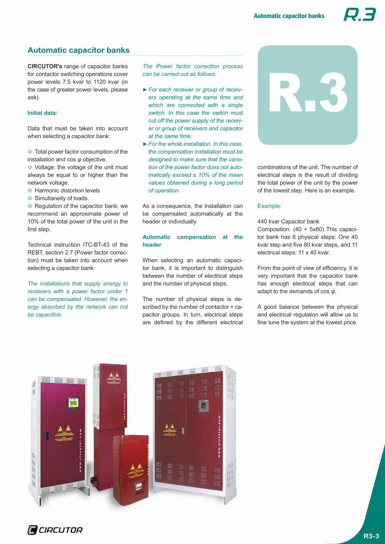
R.3CIRCUTOR's range of capacitor banks for contactor switching operations cover power levels 7.5 kvar to 1120 kvar (in the case of greater power levels, please ask).
Initial data:
Data that must be taken into account when selecting a capacitor bank:
}} Total power factor consumption of the installation and cos φ objective.}} Voltage: the voltage of the unit must
always be equal to or higher than the network voltage.}} Harmonic distortion levels}} Simultaneity of loads.}} Regulation of the capacitor bank: we
recommend an approximate power of 10% of the total power of the unit in the first step.
Technical instruction ITC-BT-43 of the REBT, section 2.7 (Power factor correc-tion) must be taken into account when selecting a capacitor bank:
The installations that supply energy to receivers with a power factor under 1 can be compensated. However, the en-ergy absorbed by the network can not be capacitive.
combinations of the unit. The number of electrical steps is the result of dividing the total power of the unit by the power of the lowest step. Here is an example.
Example:
440 kvar Capacitor bank Composition: (40 + 5x80) This capaci-tor bank has 6 physical steps: One 40 kvar step and five 80 kvar steps, and 11 electrical steps: 11 x 40 kvar.
From the point of view of efficiency, it is very important that the capacitor bank has enough electrical steps that can adapt to the demands of cos φ.
A good balance between the physical and electrical regulation will allow us to fine tune the system at the lowest price.
The Power factor correction process can be carried out as follows:
}►For each receiver or group of receiv-ers operating at the same time and which are connected with a single switch. In this case the switch must cut off the power supply of the receiv-er or group of receivers and capacitor at the same time.}►For the whole installation. In this case, the compensation installation must be designed to make sure that the varia-tion of the power factor does not auto-matically exceed ± 10% of the mean values obtained during a long period of operation.
As a consequence, the installation can be compensated automatically at the header or individually.
Automatic compensation at the header
When selecting an automatic capaci-tor bank, it is important to distinguish between the number of electrical steps and the number of physical steps.
The number of physical steps is de-scribed by the number of contactor + ca-pacitor groups. In turn, electrical steps are defined by the different electrical

Automatic capacitor banks
R3-4
Product selection table
Equipment Compensation Scope Page
AM Fixed
(Capacitor + Circuit Breaker) 2 to 30 kvar (440 V) 5
AC
M Fixed(Capacitor + Contactor + Circuit Breaker) 2 to 30 kvar (440 V) 7
AC
D Fixed(Capacitor + Contactor + Circuit Breaker + Power factor relay)
2 to 30 kvar (440 V) 9
AC
F Fixed(Capacitor + Contactor +
Fuse protection)
20 to 40 kvar (230 V)
30 to 100 kvar (440 V)11
STA
ND
AR
D (S
TD)
Automatic(Single-phase measurement)
Up to 35 kvar: STD3Up to 100 kvar: STD4Up to 180 kvar: STD6Up to 360 kvar: STD12Up to 480 kvar: STD8Up to 800 kvar: STD SC8Up to 1600 kvar: STD SC16
13
PLU
S Automatic(Three-phase measurement)
Up to 100 kvar: PLUS4Up to 180 kvar: PLUS6Up to 360 kvar: PLUS12Up to 480 kvar: PLUS8Up to 800 kvar: PLUS SC8Up to 1600 kvar: PLUS SC16
16

Automatic capacitor banks
R3-5
AMCLZ Capacitor with circuit breaker
The fixed capacitors of the AM series are single-step units that have been designed for Power factor correction procedures under constant load.
Application
Its application is mainly focused on the com-pensation of motors, transformers and instal-lations where the load levels are constant.
FeaturesDescription
Features
Operating voltage 230, 400 V (for other voltages, please ask)
Support voltage (400 V) 440 V
Capacity tolerance ± 10%
Unit composed of • CLZ capacitor • Header protection with circuit breaker
Insulation level 3 / 15 kV
Discharge resistance 75 V / 3 minutes
Overload 1.3 times the rated current permanently
Overvoltage
• 10% 8 over 24 hours • 15% up to 15 minutes over 24 hours • 20% up to 5 minutes over 24 hours • 30% up to 1 minutes over 24 hours
Contactor operating voltage 230 V
Ambient conditions
Class D temperature
Daily meanAnnual meanMaximumMinimum
45 ºC35 ºC50 ºC-25 ºC
Humidity 80% RH
Altitude 2,000 m
Construction features
Degree of protection IP 21
Colour RAL 7035 GreyRAL 3005 Maroon
Assembly conditions
Type of assembly Vertical
Ventilation Natural
Standards
CEI 60831-1, CEI 70/7, UNE 20827, UNE 20010, BS 1650, VDE 560
Automatic capacitor banks
R3-6
kvar Cut off power (kA) (A) Cable section
(mm2) Weight (kg) Dimensions (mm) width x height x depth Type Code
440 V 400 V
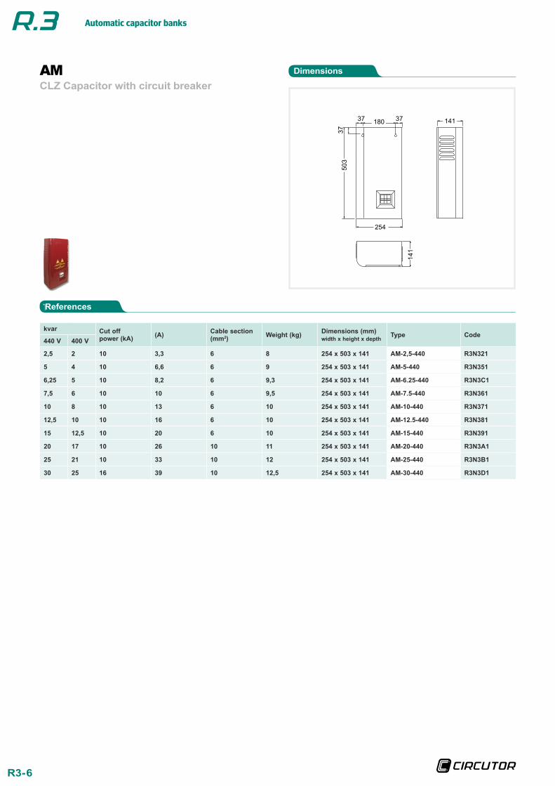
2,5 2 10 3,3 6 8 254 x 503 x 141 AM-2,5-440 R3N321
5 4 10 6,6 6 9 254 x 503 x 141 AM-5-440 R3N351
6,25 5 10 8,2 6 9,3 254 x 503 x 141 AM-6.25-440 R3N3C1
7,5 6 10 10 6 9,5 254 x 503 x 141 AM-7.5-440 R3N361
10 8 10 13 6 10 254 x 503 x 141 AM-10-440 R3N371
12,5 10 10 16 6 10 254 x 503 x 141 AM-12.5-440 R3N381
15 12,5 10 20 6 10 254 x 503 x 141 AM-15-440 R3N391
20 17 10 26 10 11 254 x 503 x 141 AM-20-440 R3N3A1
25 21 10 33 10 12 254 x 503 x 141 AM-25-440 R3N3B1
30 25 16 39 10 12,5 254 x 503 x 141 AM-30-440 R3N3D1
AMCLZ Capacitor with circuit breaker
Dimensions
References

Automatic capacitor banks
R3-7
ACMCLZ Capacitor with contactor and circuit breaker
The fixed capacitors of the ACM series are single-step units that have been designed for Power factor correction procedures in indi-vidual scenarios or under constant load.
Application
Its application is mainly focused on the com-pensation of motors, transformers and in-stallations under constant load, providing a signal that connects to the capacitor with a contactor switching operation.
FeaturesDescription
Features
Operating voltage 230, 400 V (for other voltages, please ask)
Support voltage (400 V) 440 V
Capacity tolerance ± 10%
Unit composed of
• CLZ capacitor • Contactors with pre-insertion block and quick discharge resistor
• Header protection with circuit breaker
Insulation level 3 / 15 kV
Discharge resistance 75 V / 3 minutes
Overload 1.3 times the rated current permanently
Overvoltage
• 10% 8 over 24 hours • 15% up to 15 minutes over 24 hours • 20% up to 5 minutes over 24 hours • 30% up to 1 minutes over 24 hours
Contactor operating voltage 230 V
Ambient conditions
Class D temperature
Daily meanAnnual meanMaximumMinimum
45 ºC35 ºC50 ºC-25 ºC
Humidity 80% RH
Altitude 2,000 m
Construction features
Degree of protection IP 21
Colour RAL 7035 GreyRAL 3005 Maroon
Assembly conditions
Type of assembly Vertical
Ventilation Natural
Standards
CEI 60831-1, CEI 70/7, UNE 20827, UNE 20010, BS 1650, VDE 560

Automatic capacitor banks
R3-8
References
DimensionsACMCLZ Capacitor with contactor and circuit breaker
kvar Cut off power (kA) (A) Cable section
(mm2) Weight (kg) Dimensions (mm) width x height x depth Type Code
440 V 400 V
2,5 2 10 3,3 6 8 254 x 503 x 141 ACM-2.5-440 R3P521
5 4 10 6,6 6 9 254 x 503 x 141 ACM-5-440 R3P551
6,25 5 10 8,2 6 9 254 x 503 x 141 ACM-6.25-440 R3P5C1
7,5 6 10 10 6 10 254 x 503 x 141 ACM-7.5-440 R3P561
10 8 10 13 6 10 254 x 503 x 141 ACM-10-440 R3P571
12,5 10 10 16 6 10 254 x 503 x 141 ACM-12.5-440 R3P581
15 12,5 10 20 6 11 254 x 503 x 141 ACM-15-440 R3P591
20 17 10 26 10 11 254 x 503 x 141 ACM-20-440 R3P5A1
25 21 10 33 10 12 254 x 503 x 141 ACM-25-440 R3P5B1
30 25 16 39 10 12,5 254 x 503 x 141 ACM-30-440 R3P5D1

Automatic capacitor banks
R3-9
ACDCLZ Capacitor with contactor, circuit breaker and power factor relay
The fixed capacitors of the ACD series are single-step units that have been designed for Power factor correction procedures in indi-vidual scenarios or under constant load.
Application
Its application is mainly based on the com-pensation of motors, transformers and instal-lations under constant load, with a power factor relay (DIR) that sends the capacitor activation signal when the cos φ is under the threshold established by DIR.
FeaturesDescription
Features
Operating voltage 230, 400 V (for other voltages, please ask)
Support voltage (400 V) 440 V
Capacity tolerance ± 10%
Unit composed of
• CLZ capacitor • Contactors with pre-insertion block and quick discharge resistor
• Power factor relay (DIR)
Insulation level 3 / 15 kV
Discharge resistance 75 V / 3 minutes
Overload 1.3 times the rated current permanently
Overvoltage
• 10% 8 over 24 hours • 15% up to 15 minutes over 24 hours • 20% up to 5 minutes over 24 hours • 30% up to 1 minutes over 24 hours
Contactor operating voltage 230 V
Ambient conditions
Class D temperature
Daily meanAnnual meanMaximumMinimum
45 ºC35 ºC50 ºC-25 ºC
Humidity 80% RH
Altitude 2,000 m
Construction features
Degree of protection IP 21
Colour RAL 7035 GreyRAL 3005 Maroon
Assembly conditions
Type of assembly Vertical
Ventilation Natural
Standards
CEI 60831-1, CEI 70/7, UNE 20827, UNE 20010, BS 1650, VDE 560
Automatic capacitor banks
R3-10
kvar Cut off power (kA) (A) Cable section
(mm2) Weight (kg) Dimensions (mm) width x height x depth Type Code
440 V 400 V
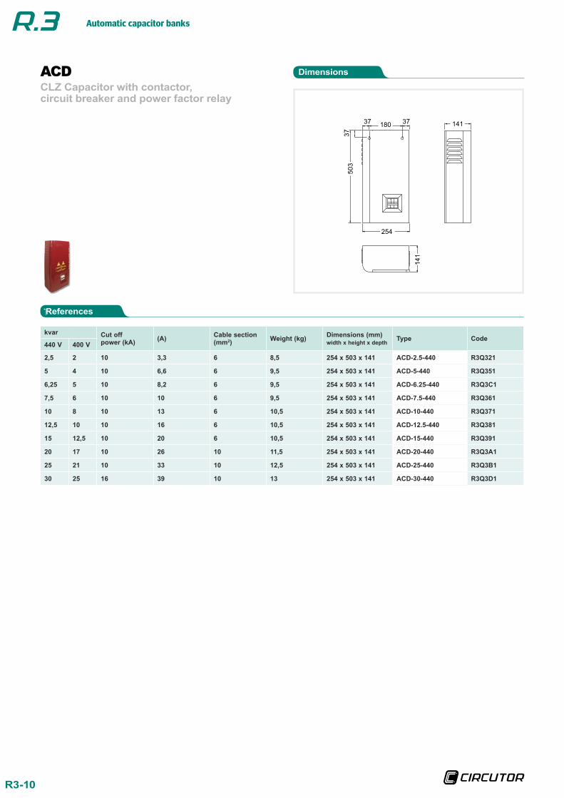
2,5 2 10 3,3 6 8,5 254 x 503 x 141 ACD-2.5-440 R3Q321
5 4 10 6,6 6 9,5 254 x 503 x 141 ACD-5-440 R3Q351
6,25 5 10 8,2 6 9,5 254 x 503 x 141 ACD-6.25-440 R3Q3C1
7,5 6 10 10 6 9,5 254 x 503 x 141 ACD-7.5-440 R3Q361
10 8 10 13 6 10,5 254 x 503 x 141 ACD-10-440 R3Q371
12,5 10 10 16 6 10,5 254 x 503 x 141 ACD-12.5-440 R3Q381
15 12,5 10 20 6 10,5 254 x 503 x 141 ACD-15-440 R3Q391
20 17 10 26 10 11,5 254 x 503 x 141 ACD-20-440 R3Q3A1
25 21 10 33 10 12,5 254 x 503 x 141 ACD-25-440 R3Q3B1
30 25 16 39 10 13 254 x 503 x 141 ACD-30-440 R3Q3D1
ACDCLZ Capacitor with contactor, circuit breaker and power factor relay
Dimensions
References

Automatic capacitor banks
R3-11
ACFCS Capacitor with contactor and fuses
The fixed capacitors of the ACF series are single-step units that have been designed for Power factor correction procedures under constant load.
Application
Its application is mainly focused on the com-pensation of motors, transformers and in-stallations under constant load, providing a signal that connects to the capacitor with a contactor switching operation.
FeaturesDescription
Features
Operating voltage 230, 400 V (for other voltages, please ask)
Support voltage (400 V) 440 V
Capacity tolerance ± 10%
Unit composed of
• CS capacitor • Contactors with pre-insertion block and quick discharge resistor
• Header protection with high rupture power (HRP)
Insulation level 3 / 15 kV
Discharge resistance 75 V / 3 minutes
Overload 1.3 times the rated current permanently
Overvoltage
• 10% 8 over 24 hours • 15% up to 15 minutes over 24 hours • 20% up to 5 minutes over 24 hours • 30% up to 1 minutes over 24 hours
Contactor operating voltage 230 V
Ambient conditions
Class D temperature
Daily meanAnnual meanMaximumMinimum
45 ºC35 ºC50 ºC-25 ºC
Humidity 80% RH
Altitude 2,000 m
Construction features
Degree of protection IP 21
Colour RAL 7035 GreyRAL 3005 Maroon
Assembly conditions
Type of assembly Vertical
Ventilation Natural
Standards
CEI 60831-1, CEI 70/7, UNE 20827, UNE 20010, BS 1650, VDE 560

Automatic capacitor banks
R3-12
230 V
kvar Cut off power (A) Fuses Cable section
(mm2) Weight (kg) Dimensions (mm) width x height x depth Type Code
20 120 kA 50 125 25 17 360 x 868 x 140 ACF-20-230 R3S141
25 120 kA 63 125 35 21 360 x 1093 x 140 ACF-25-230 R3S151
30 120 kA 75 160 50 22 360 x 1093 x 140 ACF-30-230 R3S161
40 120 kA 100 160 70 27 360 x 1093 x 140 ACF-40-230 R3S181
440 V
kvar Cut off power (A) Fuses Cable section
(mm2) Weight (kg) Dimensions (mm) width x height x depth Type Code
440 400
12,5 10 120 kA 16 35 6 12 360 x 868 x 140 ACF-12.5-440 R3S421
15 12,5 120 kA 20 35 10 13 360 x 868 x 140 ACF-15-440 R3S431
20 17 120 kA 26 50 10 14 360 x 868 x 140 ACF-20-440 R3S441
25 21 120 kA 33 63 10 15 360 x 868 x 140 ACF-25-440 R3S451
30 25 120 kA 39 80 16 16 360 x 868 x 140 ACF-30-440 R3S461
37,5 31 120 kA 49 80 25 17 360 x 868 x 140 ACF-37.5-440 R3S481
50 42 120 kA 66 125 35 21 360 x 868 x 140 ACF-50-440 R3S491
60 50 120 kA 79 160 50 22 360 x 1093 x 140 ACF-60-440 R3S4A1
75 63 120 kA 99 160 70 24 360 x 1093 x 140 ACF-75-440 R3S4B1
100 80 120 kA 131 160 70 29 360 x 1093 x 140 ACF-100-440 R3S4D1
ACFCS Capacitor with contactor and fuses
Dimensions
References
A (mm)
ACF-50 324
ACF-100 549

Automatic capacitor banks
R3-13
Automatic capacitor banksSTANDARD (STD)
The capacitor banks of the STD series have been designed for power compensation pur-poses in networks with fluctuating loads and power variations during seconds, so that the switching operations can be carried out by contactors.
Application
Its simple installation, state-of-the-art tech-nology and robustness make the STD series units the ideal equipment to compensate in-stallations with fluctuating load levels.
FeaturesDescription
Features
Operating voltage 230, 400 V (for other voltages, please ask)
Support voltage (400 V) 440 V
Capacity tolerance 0, ± 10%
Unit composed of
• CLZ capacitor (except STD3 and STD4) • Contactors with pre-insertion block and quick discharge resistor • Header protection with high rupture power (HRP). NH-00 Series • Power factor regulator of the computer m series, with digital display and 6 or 12 relay outputs, depending on the type
Add-ons
• Manual capacitor bank header switch • Automatic capacitor bank header switch • Automatic switch + Earth leakage protection at the capacitor bank's header • Forced ventilation unit + thermostat • Polycarbonate plate to protect against direct contacts • Auto-transformer 400/230 V
Insulation level 3 / 15 kV
Discharge resistance 75 V / 3 minutes
Overload 1.3 times the rated current permanently
Overvoltage
• 10% 8 over 24 hours • 15% up to 15 minutes over 24 hours • 20% up to 5 minutes over 24 hours • 30% up to 1 minutes over 24 hours
Contactor operating voltage 230 V
Ambient conditions
Class D temperature
Daily meanAnnual meanMaximumMinimum
45 ºC35 ºC50 ºC-25 ºC
Humidity 80% RH
Altitude 2,000 m
Construction features
Degree of protection IP 21
Colour RAL 7035 GreyRAL 3005 Maroon
Assembly conditions
Type of assembly Vertical
Ventilation Natural or forced, depending on the option
Distance between capacitors Minimum, 2 cm
Standards
CEI 60831-1, CEI 70/7, UNE 20827, UNE 20010, BS 1650, VDE 560

Automatic capacitor banks
R3-14
References
Automatic capacitor banksSTANDARD (STD)
kvar Composition Switch (A) Cable section (mm2)
Weight (kg)
Dimensions (mm) width x height x depth
Type Code440 V 400 V7,5 6,2 ( 2,5 + 5 ) 63 6 28 290 x 464 x 170 STD3-7.5-440 R3661012,5 10 ( 2,5 + 5 + 5 ) 63 6 28 290 x 464 x 170 STD3-12.5-440 R3662017,5 14 ( 2,5 + 5 + 10 ) 63 10 30 290 x 464 x 170 STD3-17.5-440 R3662525 21 ( 5 + ( 2 x 10 )) 63 16 31 290 x 464 x 170 STD3-25-440 R3663531,25 26 ( 6.25 + ( 2 x 12.5 )) 63 16 32 290 x 464 x 170 STD3-31.25-440 R3663737,5 31,25 ( 7.5 + ( 2 x 15 )) 63 16 33 290 x 464 x 170 STD3-37.5-440 R3663943,75 36 ( 6.25 + ( 3 x 12.5 )) 100 25 36 460 x 930 x 230 STD4-43.75-440 R3461050 41 ( 10 + ( 2 x 20 )) 160 25 37 460 x 930 x 230 STD4-50-440 R3461555 45 ( 5 + 10 + ( 2 x 20 )) 160 35 40 460 x 930 x 230 STD4-55-440 R3462060 50 ( 3 x 20 ) 160 35 40 460 x 930 x 230 STD4-60-440 R3462270 58 ( 10 + ( 3 x 20 )) 160 50 41 460 x 930 x 230 STD4-70-440 R3463080 66 ( 4 x 20 ) 250 70 41 460 x 930 x 230 STD4-80-440 R3463587,5 72 ( 12.5 + ( 3 x 25 )) 250 70 43 460 x 930 x 230 STD4-87.5-440 R34636100 83 ( 4 x 25 ) 250 95 46 460 x 930 x 230 STD4-100-440 R34637105 87 ( 15 + ( 3 x 30 )) 250 95 66 615 X 1330 X 400 STD6-105-440 R3P655120 99 ( 4 x 30 ) 400 95 74 615 X 1330 X 400 STD6-120-440 R3P656135 112 ( 15 + ( 4 x 30 )) 400 95 81 615 X 1330 X 400 STD6-135-440 R3P657150 124 ( 5 x 30 ) 400 120 82 615 X 1330 X 400 STD6-150-440 R3P658165 136 ( 15 + ( 5 x 30 )) 400 120 83 615 X 1330 X 400 STD6-165-440 R3P659180 149 ( 6 x 30 ) 400 150 87 615 X 1330 X 400 STD6-180-440 R3P660195 161 ( 15 + ( 6 x 30 )) 400 150 117 1180 x 1340 x 360 STD12-195-440 R3R700210 173 ( 7 x 30 ) 400 185 119 1180 x 1340 x 360 STD12-210-440 R3R701225 186 ( 15 + ( 7 x 30 )) 400 185 121 1180 x 1340 x 360 STD12-225-440 R3R702240 198 ( 8 x 30 ) 630 185 124 1180 x 1340 x 360 STD12-240-440 R3R703255 210 ( 15 + ( 8 x 30 )) 630 240 127 1180 x 1340 x 360 STD12-255-440 R3R704270 223 ( 9 x 30 ) 630 240 130 1180 x 1340 x 360 STD12-270-440 R3R705285 235 ( 15 + ( 9 x 30 )) 630 240 133 1180 x 1340 x 360 STD12-285-440 R3R706300 248 ( 10 x 30 ) 630 240 136 1180 x 1340 x 360 STD12-300-440 R3R707315 260 ( 15 + ( 10 x 30 )) 630 240 139 1180 x 1340 x 360 STD12-315-440 R3R708330 273 ( 11 x 30 ) 630 2x150 142 1180 x 1340 x 360 STD12-330-440 R3R709345 285 ( 15 + ( 11 x 30 )) 800 2x150 145 1180 x 1340 x 360 STD12-345-440 R3R710360 298 ( 12 x 30 ) 800 2x150 155 1180 x 1340 x 360 STD12-360-440 R3R711330 273 ( 30 + ( 5 x 60 )) 800 2x150 232 1180 x 1650 x 360 STD8-330-440 R3E462360 298 ( 6 x 60 ) 800 2x185 240 1180 x 1650 x 360 STD8-360-440 R3E464390 322 ( 30 + ( 6 x 60 )) 1000 2x185 245 1180 x 1650 x 360 STD8-390-440 R3E466420 347 ( 7 x 60 ) 1000 2x240 250 1180 x 1650 x 360 STD8-420-440 R3E470450 372 ( 30 + ( 7 x 60 )) 1000 2x240 255 1180 x 1650 x 360 STD8-450-440 R3E472480 397 ( 8 x 60 ) 1250 2x240 260 1180 x 1650 x 360 STD8-480-440 R3E474450 372 ( 50 + ( 4 x 100 )) 1000 2x185 270 1180 x 1895 x 460 STD SC8-450-440 R3E499500 413 ( 5 x 100 ) 1000 2x240 275 1180 x 1895 x 460 STD SC8-500-440 R3E500550 454 ( 50 + ( 5 x 100 )) 1250 2x240 280 1180 x 1895 x 460 STD SC8-550-440 R3E501600 496 ( 6 x 100 ) 1250 2x240 285 1180 x 1895 x 460 STD SC8-600-440 R3E502650 537 ( 50 + ( 6 x 100 )) 1600 3x150 290 1180 x 1895 x 460 STD SC8-650-440 R3E503700 579 ( 7 x 100 ) 1600 3x150 295 1180 x 1895 x 460 STD SC8-700-440 R3E504750 620 ( 50 + ( 7 x 100 )) 1600 3x185 300 1180 x 1895 x 460 STD SC8-750-440 R3E505800 661 ( 8 x 100 ) 1600 3x185 305 1180 x 1895 x 460 STD SC8-800-440 R3E506900 744 ( 50 + 50 + ( 8 x 100 )) 1600 / 400 3x150 / 185 525 2460 x 1895 x 460 STD SC16-900-440 R3E576950 785 ( 50 + ( 9 x 100 )) 1600 / 400 3x185 / 185 535 2460 x 1895 x 460 STD SC16-950-440 R3E5771000 826 ( 10 x 100 ) 1600 / 400 3x185 / 185 545 2460 x 1895 x 460 STD SC16-1000-440 R3E5791050 868 ( 50 + ( 10 x 100 )) 1600 / 630 3x185 / 240 555 2460 x 1895 x 460 STD SC16-1050-440 R3E5801100 909 ( 11 x 100 ) 1600 / 630 3x185 / 2x120 565 2460 x 1895 x 460 STD SC16-1100-440 R3E5811150 950 ( 50 + ( 11 x 100 )) 1600 / 800 3x185 / 2x150 575 2460 x 1895 x 460 STD SC16-1150-440 R3E5821200 992 ( 12 x 100 ) 1600 / 1000 3x185 / 2x185 585 2460 x 1895 x 460 STD SC16-1200-440 R3E5831300 1074 ( 13 x 100 ) 1600 / 1000 3x185 / 2x240 590 2460 x 1895 x 460 STD SC16-1300-440 R3E5841400 1157 ( 14 x 100 ) 1600 / 1250 3x185 / 3x120 595 2460 x 1895 x 460 STD SC16-1400-440 R3E5881500 1240 ( 100 + ( 7 x 200 )) 1600 / 1600 3x185 / 3x150 600 2460 x 1895 x 460 STD SC16-1500-440 R3E5901600 1322 ( 100 + 100 + ( 7 x 200 )) 1600 / 1600 3x185 / 3x185 605 2460 x 1895 x 460 STD SC16-1600-440 R3E591

Automatic capacitor banks
R3-15
Dimensions
Automatic capacitor banksSTANDARD (STD)
STD 3
STD 6
STD SC8
STD SC16 = 2 x STD SC8 + 100 mm width
STD 12
STD 4
1340
1240
100
1180 360
(C)2
045
(A)1180
(B)460
CS300
CS500
CS700
A
1180
1180
1180
B
460
460
460
C
1670
1895
2045
STD 8
1650
1550
100
1180 360

Automatic capacitor banks
R3-16
Automatic capacitor banksPLUS
Capacitor bank with an intelligent state-of-the-art regulator, capable of measuring the three installation phases and compensating the total power factor consumption accu-rately.
The PLUS capacitor bank has been de-signed with CIRCUTOR's measurement sys-tem technology, effectively creating a com-pensation + measurement unit. Its displays any electrical parameter of the network in real time and records it in its internal memory, with maximum and minimum values, date and hour.
}} The user can benefit from the following advantages as a result of the many new features:The measurement of the three phases guarantees the real compensation of the installation.}} Protection against harmonics, with an
anti-resonance system}} Easy installation, fully self-programmable,
operation start-up by pressing just one key}} New regulation program that enables the
use of any type of sequence}} Greater continuity of the service, control
and display of leakages, with step-by-step earth leakage protection}} Internal temperature sensor, for the pro-
tection against excessive temperatures, with alarm and/or disconnection system}} Test function to check the whole unit by
pressing just one key}} The communications system can be used
by the user to display the distance of unit pa-rameters and the network for the preventive supervision and maintenance tasks.
Application
Its application is mainly focused on the com-pensation of installations with different loads, which require a regulated compensation, as a result of the power factor variations.
Features
Description
FeaturesOperating voltage 230, 400 V (for other voltages, please ask)Support voltage 440 VCapacity tolerance 0, ± 10%
Unit composed of
• CS, CV ... capacitor • Contactors with pre-insertion block and quick discharge resistor • Individual protection of each step with high rupture power
(HRP). NH-00 or Neozed series, depending on the type • Two-pole earth leakage protection system for regulator
and capacitor bank switching operations • Power factor regulator of the computer PLUS series, with digital display and 8 or 14 relay outputs, depending on the type:
- Integral control of the three phases - Power analyzer to monitor cos φ, Power factor, P,
Q, S and voltage and current harmonics - Alarms for overvoltages, undervoltages, harmonics,
temperature and lack of compensation
Add-ons
• Manual capacitor bank header switch • Automatic capacitor bank header switch • Automatic switch + Earth leakage protection at the capacitor bank's header • Forced ventilation unit + thermostat • Polycarbonate plate to protect against direct contacts • Auto-transformer 400/230 V
Insulation level 3 / 15 kVDischarge resistance 75 V / 3 minutesOverload 1.3 times the rated current permanently
Overvoltage
• 10 % 8 over 24 hours • 15 % up to 15 minutes over 24 hours • 20 % up to 5 minutes over 24 hours • 30 % up to 1 minutes over 24 hours
Contactor operating voltage 230 V
Ambient conditions
Class D temperature
Daily meanAnnual meanMaximumMinimum
45 ºC35 ºC50 ºC-25 ºC
Humidity 80 % RHAltitude 2,000 mConstruction featuresDegree of protection IP 21Colour RAL 7035: Grey / RAL 3005: MaroonAssembly conditionsType of assembly VerticalVentilation Natural or forced, depending on the optionDistance between capacitors Minimum, 2 cmStandardsCEI 60831-1, CEI 70/7, UNE 20827, UNE 20010, BS 1650, VDE 560

Automatic capacitor banks
R3-17
Automatic capacitor banksPLUS
References
kvar Composition Switch (A) Cable section (mm2)
Weight (kg)
Dimensions (mm) width x height x depth
Type Code440 V 400 V7,5 6,2 ( 2,5 + 5 ) 63 6 32 460 x 930 x 230 PLUS4-7.5-440 R3681012,5 10 ( 2,5 + 5 + 5 ) 63 6 32 460 x 930 x 230 PLUS4-12.5-440 R3682017,5 14 ( 2,5 + 5 + 10 ) 63 6 32 460 x 930 x 230 PLUS4-17.5-440 R3682525 21 ( 5 + ( 2 x 10 )) 63 16 32 460 x 930 x 230 PLUS4-25-440 R3683531,25 26 ( 6.25 + ( 2 x 12.5 )) 63 16 32 460 x 930 x 230 PLUS4-31.25-440 R3685037,5 31,25 ( 7.5 + ( 2 x 15 )) 63 16 32 460 x 930 x 230 PLUS4-37.5-440 R3665143,75 36 ( 6.25 + ( 3 x 12.5 )) 100 25 36 460 x 930 x 230 PLUS4-43.75-440 R3481050 41 ( 10 + ( 2 x 20 )) 160 25 37 460 x 930 x 230 PLUS4-50-440 R3481555 45 ( 5 + 10 + ( 2 x 20 )) 160 35 40 460 x 930 x 230 PLUS4-55-440 R3482060 50 ( 3 x 20 ) 160 35 40 460 x 930 x 230 PLUS4-60-440 R3482270 58 ( 10 + ( 3 x 20 )) 160 50 41 460 x 930 x 230 PLUS4-70-440 R3483080 66 ( 4 x 20 ) 250 70 41 460 x 930 x 230 PLUS4-80-440 R3483587,5 72 ( 12.5 + ( 3 x 25 )) 250 70 43 460 x 930 x 230 PLUS4-87.5-440 R34840100 83 ( 4 x 25 ) 250 95 46 460 x 930 x 230 PLUS4-100-440 R34845105 87 ( 15 + ( 3 x 30 )) 250 95 76 615 X 1330 X 400 PLUS6-105-440 R3P840120 99 ( 4 x 30 ) 400 95 84 615 X 1330 X 400 PLUS6-120-440 R3P844135 112 ( 15 + ( 4 x 30 )) 400 95 91 615 X 1330 X 400 PLUS6-135-440 R3P846150 124 ( 5 x 30 ) 400 120 94 615 X 1330 X 400 PLUS6-150-440 R3P848165 136 ( 15 + ( 5 x 30 )) 400 150 96 615 X 1330 X 400 PLUS6-165-440 R3P852180 149 ( 6 x 30 ) 400 150 97 615 X 1330 X 400 PLUS6-180-440 R3P854195 161 ( 15 + ( 6 x 30 )) 400 150 127 1180 x 1340 x 360 PLUS12-195-440 R3R864210 173 ( 7 x 30 ) 400 185 136 1180 x 1340 x 360 PLUS12-210-440 R3R870225 186 ( 15 + ( 7 x 30 )) 400 185 143 1180 x 1340 x 360 PLUS12-225-440 R3R872240 198 ( 8 x 30 ) 630 185 150 1180 x 1340 x 360 PLUS12-240-440 R3R876255 210 ( 15 + ( 8 x 30 )) 630 240 157 1180 x 1340 x 360 PLUS12-255-440 R3R882270 223 ( 9 x 30 ) 630 240 164 1180 x 1340 x 360 PLUS12-270-440 R3R890285 235 ( 15 + ( 9 x 30 )) 630 240 171 1180 x 1340 x 360 PLUS12-285-440 R3R894300 248 ( 10 x 30 ) 630 240 178 1180 x 1340 x 360 PLUS12-300-440 R3R895315 260 ( 15 + ( 10 x 30 )) 630 240 185 1180 x 1340 x 360 PLUS12-315-440 R3R896330 273 ( 11 x 30 ) 630 2x150 192 1180 x 1340 x 360 PLUS12-330-440 R3R897345 285 ( 15 + ( 11 x 30 )) 800 2x150 199 1180 x 1340 x 360 PLUS12-345-440 R3R898360 298 ( 12 x 30 ) 800 2x150 206 1180 x 1340 x 360 PLUS12-360-440 R3R899330 273 ( 30 + ( 5 x 60 )) 800 2x150 390 1180 x 1650 x 360 PLUS8-330-440 R3E562360 298 ( 6 x 60 ) 800 2x185 405 1180 x 1650 x 360 PLUS8-360-440 R3E564390 322 ( 30 + ( 6 x 60 )) 1000 2x185 420 1180 x 1650 x 360 PLUS8-390-440 R3E566420 347 ( 7 x 60 ) 1000 2x240 435 1180 x 1650 x 360 PLUS8-420-440 R3E568450 372 ( 30 + ( 7 x 60 )) 1000 2x240 450 1180 x 1650 x 360 PLUS8-450-440 R3E570480 397 ( 8 x 60 ) 1250 2x240 465 1180 x 1650 x 360 PLUS8-480-440 R3E572450 372 ( 50 + ( 4 x 100 )) 1000 2x185 232 1180 x 1895 x 460 PLUS SC8-450-440 R3E672500 413 ( 5 x 100 ) 1000 2x240 240 1180 x 1895 x 460 PLUS SC8-500-440 R3E674550 454 ( 50 + ( 5 x 100 )) 1250 2x240 245 1180 x 1895 x 460 PLUS SC8-550-440 R3E766600 496 ( 6 x 100 ) 1250 2x240 250 1180 x 1895 x 460 PLUS SC8-600-440 R3E770650 537 ( 50 + ( 6 x 100 )) 1600 3x150 255 1180 x 1895 x 460 PLUS SC8-650-440 R3E772700 579 ( 7 x 100 ) 1600 3x150 260 1180 x 1895 x 460 PLUS SC8-700-440 R3E774750 620 ( 50 + ( 7 x 100 )) 1600 3x185 265 1180 x 1895 x 460 PLUS SC8-750-440 R3E775800 661 ( 8 x 100 ) 1600 3x185 275 1180 x 1895 x 460 PLUS SC8-800-440 R3E776900 744 ( 50 + 50 + ( 8 x 100 )) 1600 / 400 3x150 / 185 510 2460 x 1895 x 460 PLUS SC16-900-440 R3E876950 785 ( 50 + ( 9 x 100 )) 1600 / 400 3x185 / 185 520 2460 x 1895 x 460 PLUS SC16-950-440 R3E8771000 826 ( 10 x 100 ) 1600 / 400 3x185 / 185 530 2460 x 1895 x 460 PLUS SC16-1000-440 R3E8791050 868 ( 50 + ( 10 x 100 )) 1600 / 630 3x185 / 240 535 2460 x 1895 x 460 PLUS SC16-1050-440 R3E8801100 909 ( 11 x 100 ) 1600 / 630 3x185 / 2x120 540 2460 x 1895 x 460 PLUS SC16-1100-440 R3E8811150 950 ( 50 + ( 11 x 100 )) 1600 / 800 3x185 / 2x150 545 2460 x 1895 x 460 PLUS SC16-1150-440 R3E8821200 992 ( 12 x 100 ) 1600 / 1000 3x185 / 2x185 550 2460 x 1895 x 460 PLUS SC16-1200-440 R3E8831300 1074 ( 13 x 100 ) 1600 / 1000 3x185 / 2x240 555 2460 x 1895 x 460 PLUS SC16-1300-440 R3E8841400 1157 ( 14 x 100 ) 1600 / 1250 3x185 / 3x120 560 2460 x 1895 x 460 PLUS SC16-1400-440 R3E8861500 1240 ( 100 + ( 7 x 200 )) 1600 / 1600 3x185 / 3x150 565 2460 x 1895 x 460 PLUS SC16-1500-440 R3E8881600 1322 ( 100 + 100 + ( 7 x 200 )) 1600 / 1600 3x185 / 3x185 570 2460 x 1895 x 460 PLUS SC16-1600-440 R3E970

Automatic capacitor banks
R3-18
Automatic capacitor banksPLUS
Dimensions
PLUS 6
PLUS 8
PLUS SC16 = 2 x PLUS SC8 + 100 mm width
PLUS 12
PLUS 4
1340
1240
100
1180 360
PLUS SC8
1650
1550
100
1180 360
(C)2
045
(A)1180
(B)460
CS300CS500CS700
A118011801180
B460460460
C167018952045

![The molecular monorail - ru.nl · PDF filetor will perform consistent and unidirectional rotational movement [3]. ... These particles, or stomatocytes, ... which results in a 180](https://static.documents.pub/doc/80x56/5aae9aa67f8b9a22118c3c08/the-molecular-monorail-runl-will-perform-consistent-and-unidirectional-rotational.jpg)


