Tina Memo No. 2010-004 Internal Memo Automatic Morphological Landmark Location using Local Image Patch Registration P.A. Bromiley, H. Ragheb and N.A. Thacker Last updated 25 / 10 / 2010 Imaging Science and Biomedical Engineering Division, Medical School, University of Manchester, Stopford Building, Oxford Road, Manchester, M13 9PT.
Transcript
Tina Memo No. 2010-004Internal Memo
Automatic Morphological Landmark Location using Local
Image Patch Registration
P.A. Bromiley, H. Ragheb and N.A. Thacker
Last updated25 / 10 / 2010
Imaging Science and Biomedical Engineering Division,Medical School, University of Manchester,
We propose a system for automatic identification of morphological landmarks in 3D medical imagevolumes. The system will be implemented as a software package comprising three components: amanual landmark identification tool, allowing the generation of training data; a global registrationtool, allowing alignment of new image volumes with volumes in the training data, in order to provideapproximate, initial landmark locations; and a local registration tool, which will refine the approximatelandmark locations using correlation between image patches around each landmark. This report dealswith initial development of the third component.
The aim of this work was to develop an algorithm capable of providing optimised transformationmodel parameters for correlation-based local image patch registration, an estimate of the goodness-of-fitof the patches, and an estimate of the covariance matrix of the optimised parameters. The algorithmwas tested using micro CT images of a Mus musculus skull. Monte-Carlo simulations were performed,demonstrating the ability of the algorithm accurately to locate landmark points and provide realisticestimates of the transformation parameter covariance matrix.
1 Introduction
Quantitative morphological analysis of biological specimens is an increasingly active research area, with the aim ofinvestigating the links between morphology, phylogeny and ecology and, once the extent of these links is understood,of using morphological analysis as a measurement tool to infer phylogenic and ecological data. One currentlypopular approach is Procrustes analysis of manually identified landmarks. Manual landmarking is time consuming,particularly when performed on 3D data, and must typically be performed for at least several tens of specimens.Therefore, morphological analysis would benefit considerably from an automatic landmark identification algorithm.
In previous work [12, 14, 13, 16, 17, 15] we developed a system for automatic location of morphometric landmarksin 2D microscope images of Drosophila wings. In this work, we aim to extend the method to deal with 3D data,with particular focus on micro-CT images of rodent skulls, and to implement the method as a software packagecomprising three components. The first, a manual landmark identification tool, has already been developed [4].This will be used to generate training data for the automatic landmark location tools. The second component willbe a global registration tool, capable of aligning previously unseen image volumes with those stored in a databaseof training data. This will provide approximate, initial landmark locations in previously unseen data. However,shape differences between the training data and the previously unseen data will prevent accurate landmark locationusing global registration. Therefore, a third component will refine the approximate landmark locations using a localregistration of image patches around each landmark in the training data. Shape variation between the training dataand the previously unseen data will be minimal for sufficiently small patches, allowing accurate landmark location.The availability of multiple training data sets, and thus multiple hypothesised locations for each landmark, willthen allow further refinement; for example, a subset of the hypothesised location with the best goodness-of-fitcould be chosen, and then averaging performed to provide the final, automatic landmark location.
This report focuses on initial development of the third component; the local image patch registration. The proposedalgorithm extracts three orthogonal image patches from around each landmark in the training data, aligned withthe three major axes of the original image volume. Orthogonal patches, rather than a 3D data block, are useddue to the high resolution of the image volumes used in morphological analysis; the patches must incorporate localbut not global structure in order that landmarks are located on the basis of local shape, and visual inspection ofexample data sets indicated that a patch width of several tens of pixels will be sufficient to meet this. Orthogonalpatches of this size are sufficient to ensure that the errors on the optimised transformation model parameters will
be limited by factors other than the amount of data used in the likelihood calculation i.e. using a 3D block wouldincrease the processor time required by the algorithm without having any measurable effect on the final accuracy.
Rather than use the image patches directly, the algorithm used the horizontal and vertical derivatives of thepatches. This provides independence to any constant offset between the intensity in the training and previouslyunseen data sets, such as might be introduced by differences in scanner parameters. However, a linear intensityscaling might also be expected, particularly when matching data from species of different sizes, due to differencesin bone density/mineralisation. Therefore, a parameter is incorporated into the likelihood allowing for a linearscaling between patch derivatives. This likelihood is then optimised in order to register the derivative patches fromthe training data (i.e. the target) to those from previously unseen data (i.e. the source). In this report we use atransformation model consisting of three translation parameters; extension of the system to include other modesof variation would be trivial.
In order to make efficient use of the optimised transformation model parameters, the system is also required toestimate the goodness-of-fit of the source and target volumes, in order to allow detection of mis-registrations andto provide an indication of which hypothesised landmark locations, from multiple sets of training data, to use inthe final, automatic landmark location. Furthermore, the system is required to estimate the covariance matrix onthe optimised transformation model parameters, both as a test of measurement accuracy and in order that errorpropagation can be used to calculate the covariance matrix on the automatic landmark location, such that thelocation errors can be accounted for in any subsequent analysis of the results. A goodness-of-fit measure is providedby the χ2 per degree of freedom at the optimum, although this requires an accurate estimate of the noise on thedata incorporated into the χ2 calculation. An estimate of the covariance matrix on the optimised transformationmodel parameters can be provided by the Minimum Variance Bound (MVB) [2]. In previous work [20, 7, 8, 5, 6],we investigated the use of this technique to estimate the errors on the transformation model parameters for mutualinformation based registration of MR images of the brain. Bansal et al. [1] have investigated a similar method inthe same application. Here, we adopt a modified approach compared to our earlier work. Rather than attemptingto calculate the MVB as a sum over individual data terms, we calculate it using finite stepping on the χ2 function,in order to avoid problems with numerical stability.
The remainder of this report is organised as follows. Section 2 presents some observations on the process ofmanual landmarking, and on the global registration stage of the automatic landmark location procedure. Section3 describes the theoretical development of the local registration algorithm and the corresponding goodness-of-fitand parameter covariance estimation procedures. Evaluation of the algorithm was performed using Monte-Carlosimulations of local patch registration on micro-CT images of a M. musculus skull; the experimental procedure isdescribed in Section 4, and the results of the evaluation are presented in Section 5. The aim of this initial phase oftesting was to evaluate the numerical stability and implementation of the algorithm, and the experimental designreflected this; all experiments involved registration of patches from identical images, such that the correct solutionwas known exactly. The results therefore do not test the use of the algorithm in automatic landmarking, wherelandmark positions must be transferred between images of different rodent skulls and differences in shape may bepresent. More realistic experiments will be performed at a later date and presented in a companion document.Conclusions are presented in Section 6, together with a discussion of the limitation of the evaluation methodologyand its relation to the application more realistic data sets incorporating variation in shape.
2 Real-world Issues
Here we discuss the main issues we should consider in order to deal with real-world data.
2.0.1 Scale
In morphological analysis, apparent scale change is introduced due to developmental processes as well as theinherent differences in mature samples. However, unlike more general computer vision problems, the overall scaleof a given structure in an image is largely fixed by the nature of the imaging process and the overall structuresare very similar. We therefore assume, in the development of the current algorithm, that one overall approximatescaling of the data is sufficient to allow us to locate small sub-regions (e.g. a scale factor error of 5% will producea negligible one-pixel shift in data at the edges of a region 40 pixels across). This scaling will be provided by theglobal registration stage of the automatic landmarking procedure; the accuracy of this assumption will be evaluatedduring testing of the completed system, when all components are available.
3
Figure 1: Manual mark-up strategy for locations with low curvature using two distinct landmarks; left: linearcombination of existing points; right: parallel lines as guides to mark-up the tangential point. Full pointers showexisting points; empty pointer show new points.
2.0.2 Rotation
A mark-up strategy is needed mainly to make sure all example landmarks are correctly selected manually. Forinstance, there are places on the skull surface where the principal curvature in one direction (or even both directions)is very small (Fig. 1). These places are obviously not the best candidates for selecting landmarks, because it isdifficult to maintain consistency between datasets. When such “semi-landmarks” are needed it is usually the casethat two or more existing landmarks are used as a constraint. However, using a linear combination model to definea line of intersection results in a positional estimate that is correlated with the other two landmarks, indeed, themeasurement between the constraint points is fixed entirely by their positions. The new point does not represent afully independent measurement, and this invalidates the independence assumptions needed in later shape analyses(e.g. PCA). However, if the two reference points are used instead to define a tangent and a point of extremumidentified, manual identification accuracy is then determined by the curvature of the bone boundary, which givesa better reflection of the location precision. As this approach is equivalent to specifying a rotation, it is consistentwith localising the mark-up point using a reference image with fixed orientation. This approach therefore alsosimplifies the numerical implementation of the localisation process.
The accuracy of the automated estimate of initial orientation will need to be better than a degree in order to limitthe effects of error on localisation (e.g. an error of half a degree will produce subpixel effects at the edge of a40 pixel wide block) and its covariance. By matching to multiple candidate references we can however mitigateagainst large rotation errors using statistical match criteria. Again, we assume that this scaling will be providedby the global registration stage of the automatic landmarking procedure; the accuracy of this assumption will beevaluated during testing of the completed system, when all components are available. Due to the observations inthis and the previous section, for the purpose of the evaluation presented here the transformation model used inthe local patch registration is limited to translation components only; the suitability of this model will be evaluatedwhen both the local and global registration components are incorporated into the automatic landmark locationsoftware, at which point any requirement for additional modes of variation will be reassessed.
2.0.3 Irregularities
For specific local bone structures there are a variety of shapes for which consistent landmark points need to beestimated. Hence, a clear strategy of defining landmarks on such structures must be specified prior to manuallandmark identification. Automation is therefore a challenging problem, because in some cases there is obviouslyno systematic way to define robust features using local information. One approach is to learn an appearancemodel [9] corresponding to the three orthogonal slices of each block. However, we expect that we will have towork with a minimum number of reference examples (insufficient to construct an accurate model), while at thesame time topological differences between corresponding locations for identified structures are likely to be quitelarge. It is therefore unlikely, in general, that the examples provided will be efficiently described by a single linearmodel. If we can identify markup locations without using appearance models it is therefore sensible to do so[12, 14, 13, 16, 17, 15].
These facts suggest the alternative approach of matching individual reference data separately, subject to nominaldeformations (which in the simplest case might be scaled or rigid matching). Note that, in general, we may wish tomake simple linear models out of the individual example blocks. In doing this, we should shortlist a number of best“candidate” points matching against the landmark from different example structures found in our reference blocks.This strategy has the advantage of avoiding a highly dimensioned optimisation, which is time-consuming, replacingit with several low-dimensioned optimisations. If we assume that the candidate matches have been matched to the
4
data perfectly, then the corresponding reference landmark locations can be combined using a weighted mean anderrors on this estimate propagated accordingly. However, this is beyond the scope of the current paper.
2.0.4 Missing Data
In addition, it is a matter of concern in morphological studies incorporating species with small, delicate bonestructures (which may be damaged during sample preparation) or museum specimens (which may have becomedamaged during long-term storage and handling) that parts of the data are missing in some cases. This resultsin inconsistency in the landmark points among samples. In our opinion this is an extreme case of irregularitieswhere features corresponding to missing data do not exist at all. Hence, our method must be able to recognisesuch cases so that landmarks corresponding to these locations could be labelled as impossible/virtual landmarks.In order to quantitatively indicate how well sample data conforms to a predefined model, we plan to define a χ2
based hypothesis. Using this technique we also expect to be able to inform the user of those occasions when morereference examples are needed.
3 Theoretical Development of the Algorithm
3.1 Template Matching
The aim of this work is to take an image patch I centred on a landmark location in an image volume for whicha set of landmarks have already been manually identified, and to optimise a set of transformation parametersthat bring this patch into alignment with a second image volume, by comparing I to an image patch J at theequivalent, transformed position in the second volume. Once this template matching task has been performed,the landmark location from the first image, when transformed using the optimised transformation parameters,gives an estimate of the landmark location in the second volume. This can be presented for visual inspectionand refinement; however, a goodness-of-fit test and an estimation of the covariance matrix on the transformationparameters can also be obtained to provide some level of automatic accuracy checking, allowing the software toalert the user to landmarks where the fitting process is known to have failed.
The log-likelihood function for matching image patches I and J , where an overall scaling difference is expectedbetween the two images, is
lnL =
N∑
i=1
− (γIi − Ji)2
2σ2E
where Ii is a pixel from image patch I, Ji is a pixel from the equivalent position in image patch J (i.e. afterhaving transformed one of the images using the transformation parameters being optimised; for the moment, wedo not specify which image is being transformed), i is an iterator over the pixels in the patches, N is the number ofterms in the sum i.e. the number of pixels in each patch, γ accounts for the overall scaling difference between theimages, and σE is the effective noise i.e. the expected standard deviation of the difference between the patches atperfect alignment, assuming that there is no difference in shape between the structures in the two image patches.Therefore, using error propagation,
σ2e = γ2σ2
I + σ2J
where σI is the standard deviation of the noise on image patch I and σJ is the standard deviation of the noise onimage patch J i.e. the expected error on the difference between the images is the sum in quadrature of the noiseon the individual patches, with γ taken into account. If it is assumed that the noise is the result of an additiveprocess occurring during image acquisition i.e. is independent of image contents, then it follows that σI ≈ σJ , and
σ2e = (γ2 + 1)σ2
I
so
lnL =
N∑
i=1
− (γIi − Ji)2
2(γ2 + 1)σ2I
The constant factor of −1/2 is usually ignored when writing the log-likelihood function, using the transformation-invariance characteristic of maximum-likelihood techniques (i.e. optimising any monotonic function of the likelihoodwill give the same result as optimising the likelihood itself). However, this factor is retained here in order that thelikelihood can also be used for covariance estimation, which is only possible when all scaling constants are retained.
5
3.2 Goodness-of-fit Estimation
Goodness-of-fit estimation was performed by calculating the χ2 for the matching process [2]
χ2 =
N∑
i=1
(γIi − Ji)2
σ2E
The concept behind χ2 optimisation is that, if the model is a good fit to the data, then the only differences inthe (γIi − Ji)
2 term at the optimum of the fitting process are due to random noise. The numerator of the sum istherefore expected to be equal to NσE , where N is the total number of terms in the sum, giving a χ2 of N , orequivalently a χ2 of one per degree-of-freedom. In theory, a small adjustment to N should be made by subtractingthe number of parameters optimised in the process; however, since we are dealing with three parameters and≈ 10, 000 data terms this is insignificant and can be ignored and the number of degrees-of-freedom assumed tobe equal to the number of terms in the sum. Any departure from the expected χ2/D.O.F of 1 indicates poorgoodness-of-fit, which could either be due to an inability of the model to fit the data or a failure of the optimiserto converge on a global minimum. Since the χ2 distribution function is known, a probabilistic interpretation canbe placed on the result.
It will be noted that there is a close similarity between this form of the χ2 and the log-likelihood. One ma-jor difference is that log-likelihoods are frequently constructed with arbitrary scaling, taking advantage of thetransformation-invariance of maximum likelihood estimators. However, in cases where the log-likelihood is in-tended for uses beyond simply finding its (transformation-independent) optimum, e.g. for covariance estimation,the scaling factors must be retained. Due to the similarities between the log-likelihood and the χ2, and the fact thatthe χ2 must be properly scaled in all cases such that it can be compared to the known χ2 distribution function [2],we can therefore state that the log-likelihood is properly scaled (in the sense that it can be used in the calculationof the Minimum Variance Bound; see below) when it is distributed according to −2logL = χ2. This has lead someresearchers (e.g. [3]) to assert that the χ2 is the more fundamental quantity than likelihood. We refrain fromfurther comment here; additional material is available in [7].
χ2-based goodness-of-fit testing depends on the absolute value of the χ2 and it is therefore essential that the σE
term is a genuine estimate of noise on the data terms i.e. it is not simply the original image noise, but must includethe effects of all steps of the algorithm. Since the algorithm operates on image derivatives, and these are calculatedusing finite differencing i.e. an equation of the form
δIi
δi=
Ii+1 − Ii−1
2
error propagation implies an additional factor of 2 i.e.
σ2I =
σ2Io
2
where I is the derivative patch and Io is the original patch from which this derivative was obtained. However, it mustalso be remembered that the image patch Io is not simply a patch of raw image data but, in the case of the patchfrom the source volume, has been interpolated from the original data (during registration, the source image mustbe interpolated on the voxel grid of the target image using the current transformation model parameters, so thatthe voxel values used in the cost function originate from the same spatial positions). Since interpolation involvesaveraging over neighbouring voxels, it may have an effect on noise level that is a function of the transformationmodel parameters. This effect has been studied extensively in the area of medical image registration [18, 8].
In the experimental method used here this complexity was avoided by adding noise to the image patches afterinterpolation, so that subsequent error propagation involved only the γ scaling and differential terms. Furthermore,the same image was used as both the source and target volume, primarily to ensure that there was no intrinsicshape variation between the two and that the correct registration solution was known, allowing the accuracy ofthe results to be evaluated. However, this also had the effect that the intrinsic image noise i.e. the noise addedto the underlying data during image acquisition, was identical between the two volumes, so had no random effectand instead acted like structure or texture. Therefore, for these experiments
σ2E =
(γ2 + 1)σ2A
2
where σA was the standard deviation of the noise added to the patches in the course of the Monte-Carlo experiment.In the final version of the software, used for automatic landmark placement, it is intended that the noise will bemeasured directly from the interpolated patches using the techniques described by [11], such that the same equationcan be used. Further comments on this issue are made in Section 6.1.
6
3.3 Estimating the Scaling Factor
γ can be estimated through the usual maximum likelihood procedure i.e. setting the first derivative of the log-likelihood function, with respect to γ, equal to zero and solving for γ. So
δlnL
δγ=
−1
2σ2I
N∑
i=1
[2(γIi − Ji)Ii
1 + γ2+
(γIi − Ji)22γ
(1 + γ2)2] = 0
andN
∑
i=1
(γIi − Ji)2γ
1 + γ2=
N∑
i=1
(γIi − Ji)Ii
Multiplying both sides by (1 + γ2), expanding the square and simplifying gives
N∑
i=1
[(1 − γ2)IiJi + γ(J2i − I2
i )] = 0
PutN
∑
i=1
I2i = |I|2 and
N∑
i=1
J2i = |J |2
and use the familiar expression for the IiJi dot-product i.e.
N∑
i=1
IiJi = |I||J |cosφ
where φ is a measure of the dissimilarity between the patches; if we assume that the transformation containssufficient modes of variation to bring the image patches into perfect alignment, such that the only remainingdifference between them is random noise, then we can assume that φ ≈ 0 i.e. cosφ ≈ 1, so
This is quadratic in γ, and so can be solved using the usual expression
γ =−b ±
√b2 − 4ac
2a
wherea = −|I||J | b = |J |2 − |I|2 c = |I||J |
giving
γ =|J ||I| or γ =
−|I||J |
The moduli of the image |I| and |J | must be positive, as must γ, and so the first solution is the physical one, andprovides the method for estimating γ (the second represents cases where the scaling includes an inversion, whichis not expected with the images used here).
3.4 Covariance Estimation
The maximum achievable accuracy, i.e. minimum achievable covariances, on the parameter estimates provided bya maximum likelihood technique is given by the minimum variance bound (otherwise known as the Cramer-Raobound or Frechet inequality; it was first discovered by Aitken and Silverstone)
C−1
θ ≤<∂ log L
∂θr
∂ log L
∂θs
>
or
C−1
θ ≤ − <∂2 log L
∂θr∂θs
>= −∂2 log L
∂θr∂θs
∣
∣
∣
∣
∣
θ=θmax
where θ is the vector of parameters being optimised and θmax is the vector of parameter values at the optimum.(a derivation is provides in [7]). This states that the variance of a given parameter, or the covariance of a pair
7
of parameters, is bounded by the second differential of the likelihood function with respect to the parameter(s).A simple way to view this result is that the accuracy with which the parameters can be determined is dictatedby the width of the likelihood function around the optimum; the narrower the function (i.e the greater its seconddifferential) the more accurately the position of the optimum can be located.
The condition for achieving the minimum variance bound is that the log-likelihood function is quadratic i.e. thatthe likelihood function is Gaussian. Note that this is a statement about the shape of the likelihood function, notabout the error distribution on individual data terms contributing to it. Therefore, the Central Limit Theoremwill ensure that the shape of the likelihood function converges to a Gaussian as the number of individual datacontributing to the likelihood grows, even if the error distribution on the individual data is not Gaussian, as longas the errors on the data are not highly correlated. This condition is met in most computer vision and imageanalysis tasks, and so the minimum variance bound can be used directly as an estimate of the errors in such tasksi.e. we can assume that we will achieve the bound due to the large amount of data available. In previous work[20, 7, 8, 5, 6] we demonstrated the application of this approach to the estimation of the covariances for globalregistration of medical images using mutual information. Here we apply a similar approach to the estimation ofcovariances for the image patch registration.
Due to the relationship between log-likelihood and χ2, the expression for the minimum variance bound can berestated in terms of the individual data terms in the χ2 sum; let these be called the χi, so [7]
C−1
θ =∑
i
(▽θχi)T ⊗ (▽θχi)|θ=θmax
However, in previous work [8, 5, 6] summing over the individual data terms in this way was found to be quiteunstable and susceptible to image noise, requiring additional steps such as estimating covariances from a range of▽θ and then taking the median value of the results. Therefore, in this work we adopt an alternative method inwhich the covariances are calculated from finite stepping on the χ2 function itself, using [19]
χ2 = χ20 + ∆θT C−1
θ ∆θ
where χ20 is the value of the χ2 function at its optimum. We can find linear equations between the unknown
elements of the inverse covariance matrix C−1
θ and the corresponding value obtained from the χ2 function. In ourcase there are transformation parameters only, which are the coordinates of the centre of the target block. We can,for instance, change the optimum values of these parameters by adding one pixel position in different combinations.With 3 parameters there are 8 combinations where (0,0,0) gives χ2
0. As the number of unknown elements in theC−1
θ matrix is 6, and by leaving the combination with non-zero values for all parameter changes ∆xi, ∆yi and∆zi, there will be 6 linear equations with closed from analytic solution as follows.
The covariance matrix Cθ is then found by inverting the C−1
θ matrix. Note that ∆xi, ∆yi and ∆zi should bechosen so that the difference between χ2(θopt + ∆θi) and χ2(θopt) becomes about unity. However, this needs tobe balanced with numerical accuracy and when dealing with pixel positions in image data, in practice one pixelchange in x, y and z directions is found to be a good choice.
8
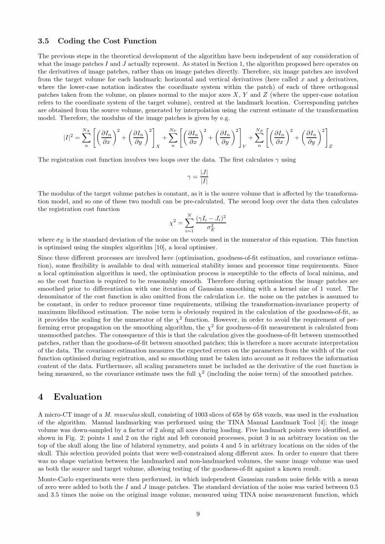
3.5 Coding the Cost Function
The previous steps in the theoretical development of the algorithm have been independent of any consideration ofwhat the image patches I and J actually represent. As stated in Section 1, the algorithm proposed here operates onthe derivatives of image patches, rather than on image patches directly. Therefore, six image patches are involvedfrom the target volume for each landmark; horizontal and vertical derivatives (here called x and y derivatives,where the lower-case notation indicates the coordinate system within the patch) of each of three orthogonalpatches taken from the volume, on planes normal to the major axes X , Y and Z (where the upper-case notationrefers to the coordinate system of the target volume), centred at the landmark location. Corresponding patchesare obtained from the source volume, generated by interpolation using the current estimate of the transformationmodel. Therefore, the modulus of the image patches is given by e.g.
|I|2 =
NX∑
n
[
(
∂In
∂x
)2
+
(
∂In
∂y
)2]
X
+
NY∑
n
[
(
∂In
∂x
)2
+
(
∂In
∂y
)2]
Y
+
NZ∑
n
[
(
∂In
∂x
)2
+
(
∂In
∂y
)2]
Z
The registration cost function involves two loops over the data. The first calculates γ using
γ =|J ||I|
The modulus of the target volume patches is constant, as it is the source volume that is affected by the transforma-tion model, and so one of these two moduli can be pre-calculated. The second loop over the data then calculatesthe registration cost function
χ2 =N
∑
i=1
(γIi − Ji)2
σ2E
where σE is the standard deviation of the noise on the voxels used in the numerator of this equation. This functionis optimised using the simplex algorithm [10], a local optimiser.
Since three different processes are involved here (optimisation, goodness-of-fit estimation, and covariance estima-tion), some flexibility is available to deal with numerical stability issues and processor time requirements. Sincea local optimisation algorithm is used, the optimisation process is susceptible to the effects of local minima, andso the cost function is required to be reasonably smooth. Therefore during optimisation the image patches aresmoothed prior to differentiation with one iteration of Gaussian smoothing with a kernel size of 1 voxel. Thedenominator of the cost function is also omitted from the calculation i.e. the noise on the patches is assumed tobe constant, in order to reduce processor time requirements, utilising the transformation-invariance property ofmaximum likelihood estimation. The noise term is obviously required in the calculation of the goodness-of-fit, asit provides the scaling for the numerator of the χ2 function. However, in order to avoid the requirement of per-forming error propagation on the smoothing algorithm, the χ2 for goodness-of-fit measurement is calculated fromunsmoothed patches. The consequence of this is that the calculation gives the goodness-of-fit between unsmoothedpatches, rather than the goodness-of-fit between smoothed patches; this is therefore a more accurate interpretationof the data. The covariance estimation measures the expected errors on the parameters from the width of the costfunction optimised during registration, and so smoothing must be taken into account as it reduces the informationcontent of the data. Furthermore, all scaling parameters must be included as the derivative of the cost function isbeing measured, so the covariance estimate uses the full χ2 (including the noise term) of the smoothed patches.
4 Evaluation
A micro-CT image of a M. musculus skull, consisting of 1003 slices of 658 by 658 voxels, was used in the evaluationof the algorithm. Manual landmarking was performed using the TINA Manual Landmark Tool [4]; the imagevolume was down-sampled by a factor of 2 along all axes during loading. Five landmark points were identified, asshown in Fig. 2; points 1 and 2 on the right and left coronoid processes, point 3 in an arbitrary location on thetop of the skull along the line of bilateral symmetry, and points 4 and 5 in arbitrary locations on the sides of theskull. This selection provided points that were well-constrained along different axes. In order to ensure that therewas no shape variation between the landmarked and non-landmarked volumes, the same image volume was usedas both the source and target volume, allowing testing of the goodness-of-fit against a known result.
Monte-Carlo experiments were then performed, in which independent Gaussian random noise fields with a meanof zero were added to both the I and J image patches. The standard deviation of the noise was varied between 0.5and 3.5 times the noise on the original image volume, measured using TINA noise measurement function, which
9
Figure 2: Locations of the landmark points used in the evaluation, shown on the M. musculus skull
is based on the width of zero-crossings in horizontal and vertical gradient histograms [11]. One hundred iterationsof the Monte-Carlo experiment were performed at each level of added noise. A random offset was introducedinto the alignment parameters prior to each registration, using samples drawn from a Gaussian distribution witha mean of zero and a standard deviation of one voxel, added to each of the transformation model parametersindependently. The initial set of transformation model parameters, final set (after optimisation), initial and finalχ2 value (including all scaling and noise terms), and estimated covariance matrix parameters for each iteration ofeach Monte-Carlo experiment were recorded.
The image patch size used in the evaluation was ±30 voxels around the landmark; this was chosen from visualinspection of the data as a patch size that encompassed local but not global structure. From this, a border of twovoxels was ignored during cost function calculation, in order to provide a margin of data from which to calculatederivatives by finite differencing. During registration, the Monte-Carlo noise was added to the patches, they weresmoothed using a Gaussian filter with a kernel size of 1 voxel, and horizontal and vertical derivatives were taken.The smoothing step was omitted when calculating the final χ2 per degree-of-freedom, in order that it did not haveto be taken into account when estimating the effective noise on the χ2.
A second set of experiments were performed in which the effects of patch size were investigated. These wereperformed at one level of added noise equal to 1σ of the image noise, and the patch size was varied from ±5 to
10
Figure 3: Measured (points with 1σ error bars) and estimated (line; grey region shows 1σ envelope) errors on thetranslation parameters for point 1, and the χ2 per degree of freedom at the optimum, for varying added noise.
±60 voxels in steps of 5 voxels. All other experimental details remained the same.
The results of each Monte-Carlo experiment (i.e. each noise level and patch size) were processed by calculating thestandard deviation of the optimised transformation model parameters in the usual way; this gave a measurementof the registration error. The error on this number (i.e. the standard deviation of the standard deviation) wasestimated by assuming it to be proportional to 1/
√N where N was the number of voxel terms summed in the
cost function. The mean and standard deviation of the final χ2 values for the 100 iterations were calculated in theusual way and divided by N to produce the χ2 per degree of freedom. Finally, the mean and standard deviationof each of the main diagonal elements of the estimated covariance matrix were calculated in the usual way to givethe estimated error.
5 Results
Figures 3 to 7 show the results from the first set of Monte-Carlo simulations, in which the level of added noisewas varied. Estimated and measured covariances on the transformation parameters for each point at each level ofadded noise are shown, together with the χ2 per degree of freedom at the optimum. Since each registration resultconsists of three optimised parameters, the covariance matrix calculated from these has three degrees of freedom,and so analysis of three of its components is sufficient to provide a complete analysis; the diagonal elements i.e.the variances are obviously the most informative, and so these are the parameters shown. The graphs show thesquare-root of the variance i.e. the standard deviation. Since both the source and target patches were drawn fromthe same image volume, the intrinsic noise on this image volume is identical between the patches, and so acts asstructure rather than random noise. Therefore, only the noise added during the Monte-Carlo simulation acts asrandom noise in the optimisation, and so a linear relationship between the error on the registration parameters,quoted as a standard deviation, and the standard deviation of the added noise would be expected (rather than adependence in which the original image noise adds in quadrature). Such a relationship can be seen in the results.
Figures 8 to 12 show the results from the second set of Monte-Carlo simulations, in which the level of added noisewas fixed at 1σ of the image noise and the patch size was varied. This symbology is the same as that used in Figs.3 to 7.
11
Figure 4: Measured (points with 1σ error bars) and estimated (line; grey region shows 1σ envelope) errors on thetranslation parameters for point 2, and the χ2 per degree of freedom at the optimum, for varying added noise.
6 Discussion and Conclusion
The main aim of the work presented in this document was to check the numerical stability and implementation ofthe proposed algorithm. The results of the Monte Carlo simulations in which added noise was varied, shown inFigs. 3 to 7, demonstrate that the method behaves as expected. The algorithm reliably converges on the correctsolution to sub-voxel accuracy, although the absolute value of the accuracy is a reflection of the fact that identicalvolumes were being matched; in more realistic applications where the source and target volumes are different theaccuracy will be correspondingly lower (see Section 6.1). The standard deviation of the errors on the optimisedtransformation model parameters depends linearly on the standard deviation of the added noise as expected. Theχ2 per degree-of-freedom also behaves as expected; it is consistently higher than the value of unity that wouldresult from a perfect registration with infinite accuracy, but is within about 1% of this value, demonstrating itssuitability for use as a goodness-of-fit measurement. The measured errors also match the estimated errors closelyand show the same functional dependency on added noise. There is some indication that the measured errors aresystematically higher than the estimated errors for some parameters and points but, since the estimated error is alower bound, this is to be expected. In interpreting these results it must be remembered that standard deviationsof parameters are being compared, not parameters themselves; in general, an accuracy of within a factor of 2 isacceptable for estimated errors, and the results presented here are comfortably within that bound. The registrationprocess is expected to destabilise at the point where the added noise dominates and the information content of thedata is no longer sufficient to produce a stable cost function; the results indicate that this is beginning to occur ataround 3 to 3.5σ.
Results from the patch size experiments are similar; the measured and estimated errors match closely, with someindication that the measured errors are consistently higher, as would be expected from the experimental design(see Section 6.1). However, the functional dependency on patch size is the same, and the χ2 per degree of freedomis consistently higher than, but within 1% of, unity as expected. Again, the registration process is expected todestabilise as the patch size is reduced to the point where there is insufficient data to produce a stable cost function;the results indicate that this occurs at patch sizes lower than around ±20 voxels on points 1 and 2 and ±10 voxelson the other points. This difference reflects the local bone structure; points 1 and 2 are on the coronoid processes,thin spikes of bone, where there is little local structure to provide information for the registration, whereas the
12
Figure 5: Measured (points with 1σ error bars) and estimated (line; grey region shows 1σ envelope) errors on thetranslation parameters for point 3, and the χ2 per degree of freedom at the optimum, for varying added noise.
remaining points are on smooth bone surfaces, providing more local information for the registration cost function.
On the basis of these results, we conclude that the algorithm is operating as expected, providing reliable parameter,error and goodness-of-fit estimates. The evaluation process must therefore now proceed to more realistic data sets,incorporating skulls that exhibit shape variation, in order to test its suitability for use in the intended applicationof automatic landmark location.
6.1 Limitations of the Method
The aim of image registration is to take two images of the same scene (i.e. the same underlying structures) that havebeen acquired with a spatial transformation between them, and to work out the parameters of that transformationsuch that the images are brought into alignment. In order to do this, a cost function describing image similarityis optimised over the parameters of the transformation model. A typical cost function, such as the χ2 used here,performs a direct voxel-to-voxel comparison between the source and target images. In order to do this, the voxelsmust be drawn from the same spatial positions. However, since a transformation is being optimised the boundariesof the voxels in the two images will not usually be the same (i.e. the voxel grids of the two images will not bealigned). Therefore, an interpolation algorithm is used to resample one of the images on the voxel grid of theother. Interpolation inevitably has an effect on image noise, as it applies some form of averaging over neighbouringvoxels around the position of the voxel being interpolated, and this effect will vary according to the mis-alignmentbetween the voxel grids.
The obvious experimental technique to use in the experiments described here would have been to add noise tothe entire image volume prior to each iteration of the Monte-Carlo experiments. However, this would lead to aproblem. The parameter-dependent effect of the interpolation algorithm on the added noise would have to be takeninto account. The noise could be measured from the interpolated patches, but this measurement would includethe effect of the intrinsic image noise (i.e. the noise added to the data during image acquisition). However, inthe experiments performed here the same volume was used as both the source and the target, in order to ensurethat the correct solution was known and that the images matched perfectly (apart from the added noise) at thesolution. Therefore, the intrinsic noise is not random variation between the source and target patches; instead, it
13
Figure 6: Measured (points with 1σ error bars) and estimated (line; grey region shows 1σ envelope) errors on thetranslation parameters for point 4, and the χ2 per degree of freedom at the optimum, for varying added noise.
acts like structure. Estimating the noise from the interpolated patches would therefore provide an over-estimatecompared to the effective noise in the registration. Trying to take account of this effect would bring us back to theoriginal problem; the effect of interpolation on noise is parameter-dependent.
In order to avoid this problem, noise was added to the image patches after interpolation. Error propagationthen became straightforward, since the only further processing applied to each patch was differentiation. Thisallowed reliable estimation of the χ2 per degree-of-freedom at the solution. However, it also resulted in a numericalinstability in the cost function, since the noise field added to the patches was unique for each patch generation i.e.each cost-function evaluation performed by the optimiser. The simplex optimiser used here maintains a record ofthe lowest cost function values it has obtained; this introduces a bias, where the optimiser can evaluate the sameset of parameters multiple times and choose the lowest value of the cost function. The result will be a reductionin registration accuracy, since accuracy is dependent on the gradient of the cost function, i.e. the effect is like anadditional noise term on the cost function.
Another effect of using the same volume as both the source and target, and the consequence that the intrinsic noiseacts as structure rather than noise, is that the information content of the data in the experiments presented here isunrealistically large, as the algorithm can match the intrinsic noise, as well as the structures in the images. This,combined with the fact that there is no underlying shape variation between the source and target, means that thecovariance estimates are unrealistically low compared to those that would be seen when matching image patchesfrom two different image volumes. This is not a drawback given the aim of these experiments; to demonstrate thatthe image patch matching algorithm and its implementation were numerically stable, and that good estimates ofthe transformation model parameters, the covariance matrix of those parameters, and the χ2 per degree of freedomcould all be obtained. However, the registration used in automatic landmark location is likely to be significantlyless accurate. Furthermore, the shape of the covariance matrix would be expected to depend on the informationcontent of the structure in the data e.g. a point on a flat, featureless bone surface will be significantly moreaccurately located along the direction perpendicular to the surface that along the directions parallel to it. Thistype of behaviour cannot be seen in the experiments presented here, due to the information content provided bythe intrinsic image noise.
To conclude, the experiment performed here is the one which allows us to evaluate the ability of the algorithm to
14
Figure 7: Measured (points with 1σ error bars) and estimated (line; grey region shows 1σ envelope) errors on thetranslation parameters for point 5, and the χ2 per degree of freedom at the optimum, for varying added noise.
find correct landmark locations, estimated errors and χ2 per degree-of-freedom at the solution. A better experimentwould involve the use of repeated acquisitions of the same image volume, but that data is not available at thistime. Finally, when the algorithm is used to match landmark locations between different skulls, a noise estimationroutine will have to be added in order to directly estimate the noise on the interpolated image patches and thusthe χ2 per degree of freedom; at that point, there will be no problem with the intrinsic image noise as it will notbe identical across the source and target patches.
References
[1] R Bansal, L H Staib, A F Laine, D Xu, J Liu, L F Posecion, and B S Peterson. Calculation of the confi-dence intervals for transformation model parameters in the registration of medical images. Med Image Anal,13(2):215–233, 2009.
[2] R J Barlow. Statistics: A Guide to the use of Statistical Methods in the Physical Sciences. John Wiley andSons Ltd., UK, 1989.
[3] J Berkson. Minimum chi-square, not maximum likelihood. Ann Stat, 8(3):457–487, 1980.
[4] P A Bromiley. TINA Memo No. 2010-007: The TINA manual landmarking tool. Technical report, ImagingSceince and Biomedical Engineering, School of Cancer and Imaging Sciences, University of Manchester, 2010.http://www.tina-vision.net/docs/memos/2010-007.pdf.
[5] P A Bromiley, M Pokric, and N A Thacker. Computing covariances for mutual information coregistration. InProc. MIUA’04, pages 77–80, 2004.
[6] P A Bromiley, M Pokric, and N A Thacker. Emprical evaluation of covariance estimates for mutual informationcoregistration. In Proc. MICCAI’04, pages 607–614, 2004.
15
[7] P A Bromiley and N A Thacker. TINA Memo No. 2003-002: Computing covariances for mutual informationcoregistration 2. Technical report, Imaging Sceince and Biomedical Engineering, School of Cancer and ImagingSciences, University of Manchester, 2003. http://www.tina-vision.net/docs/memos/2003-002.pdf.
[8] P A Bromiley and N A Thacker. TINA Memo No. 2004-001: Empirical validation of covariance estimates formutual information coregistration. Technical report, Imaging Sceince and Biomedical Engineering, School ofCancer and Imaging Sciences, University of Manchester, 2004. http://www.tina-vision.net/docs/memos/2004-001.pdf.
[9] T F Cootes, G J Edwards, and C J Taylor. Active appearance models. IEEE Trans Pattern Anal Mach Intell,23(6):681–685, 2001.
[10] J A Nelder and R Meade. A simplex method for function minimisation. Computer Journal, 7:308–313, 1965.
[11] S I Olsen. Estimation of noise in images: An evaluation. CVGIP: Graphical Models and Image Processing,55:319–323, 1993.
[12] S Palaniswamy, N A Thacker, and C P Klingenberg. TINA Memo No. 2006-002: A statistical frameworkfor detection of connected features. Technical report, Imaging Sceince and Biomedical Engineering, School ofCancer and Imaging Sciences, University of Manchester, 2006. http://www.tina-vision.net/docs/memos/2006-002.pdf.
[13] S Palaniswamy, N A Thacker, and C P Klingenberg. Automatic identification of morphometric landmarks indigital images. In Proc. BMVC’07, 10-13 September, Warwick, U.K., page 112, 2007.
[14] S Palaniswamy, N A Thacker, and C P Klingenberg. TINA Memo No. 2007-007: Automatic identifi-cation of morphometric landmarks in digital images. Technical report, Imaging Sceince and BiomedicalEngineering, School of Cancer and Imaging Sciences, University of Manchester, 2007. http://www.tina-vision.net/docs/memos/2007-007.pdf.
[15] S Palaniswamy, N A Thacker, and C P Klingenberg. Automated landmark extraction in digital images -performance evaluation. In Proc. VIE’08, July 19 - Aug 1, Xi’an, China, 2008.
[16] S Palaniswamy, N A Thacker, and C P Klingenberg. TINA Memo No. 2008-006: Automated landmarkextraction in digital images. Technical report, Imaging Sceince and Biomedical Engineering, School of Cancerand Imaging Sciences, University of Manchester, 2008. http://www.tina-vision.net/docs/memos/2008-006.pdf.
[17] S Palaniswamy, N A Thacker, and C P Klingenberg. TINA Memo No. 2008-007: Automatic identificationsystem for morphometric landmarks. Technical report, Imaging Sceince and Biomedical Engineering, School ofCancer and Imaging Sciences, University of Manchester, 2008. http://www.tina-vision.net/docs/memos/2008-007.pdf.
[18] J P W Pluim, J B Antoine Maintz, and M A Viergever. Interpolation artefacts in mutual information-basedimage registration. Computer Vision and Image Understanding, 77:211–232, 2000.
[19] W H Press, B P Flannery, S A Teukolsky, and W T Vetterling. Numerical Recipes in C. Cambridge UniversityPress, New York, 2nd edition, 1992.
[20] N A Thacker, P A Bromiley, and M Pokric. TINA Memo No. 2001-013: Computing covariances for mutual in-formation co-registration. Technical report, Imaging Sceince and Biomedical Engineering, School of Cancer andImaging Sciences, University of Manchester, 2001. http://www.tina-vision.net/docs/memos/20101-013.pdf.
16
Figure 8: Measured (points with 1σ error bars) and estimated (line; grey region shows 1σ envelope) errors on thetranslation parameters for point 1, and the χ2 per degree of freedom at the optimum, for varying patch size. Theright-hand images show expanded views of the higher patch size regions of the left-hand images.
17
Figure 9: Measured (points with 1σ error bars) and estimated (line; grey region shows 1σ envelope) errors on thetranslation parameters for point 2, and the χ2 per degree of freedom at the optimum, for varying patch size. Theright-hand images show expanded views of the higher patch size regions of the left-hand images.
18
Figure 10: Measured (points with 1σ error bars) and estimated (line; grey region shows 1σ envelope) errors on thetranslation parameters for point 3, and the χ2 per degree of freedom at the optimum, for varying patch size. Theright-hand images show expanded views of the higher patch size regions of the left-hand images.
19
Figure 11: Measured (points with 1σ error bars) and estimated (line; grey region shows 1σ envelope) errors on thetranslation parameters for point 4, and the χ2 per degree of freedom at the optimum, for varying patch size. Theright-hand images show expanded views of the higher patch size regions of the left-hand images.
20
Figure 12: Measured (points with 1σ error bars) and estimated (line; grey region shows 1σ envelope) errors on thetranslation parameters for point 5, and the χ2 per degree of freedom at the optimum, for varying patch size. Theright-hand images show expanded views of the higher patch size regions of the left-hand images.