Automatic State Reaching for Debugging Reactive Programs F. Gaucher 1 , E. Jahier 1 , B. Jeannet 2 , and F. Maraninchi 1 1 VERIMAG , Centre Equation, 2 Av. de Vignate, 38610 Gieres, France {Fabien.Gaucher, Erwan.Jahier, Florence.Maraninchi}@imag.fr http://www-verimag.imag.fr/ 2 IRISA , Campus de Beaulieu, 35042 RENNES cedex, France [email protected]http://www.irisa.fr/prive/bjeannet/ Abstract. Reactive systems are made of programs that permanently interact with their environment. Debuggers generally provide support for data and state inspection, given a sequence of inputs. But, because the reactive programs and their environments are interdependent, a very useful feature is to be able go the other way around; namely, given a state, obtain a sequence of inputs that leads to that state. This problem is equivalent to general safety properties verification, which is notoriously undecidable in presence of numeric variables. However, a lot of progress has been done in recent years through the development of model checking and abstract interpretation based techniques. In this article, we take advantage of those recent advances to implement a fully automatic state reaching capability inside a debugger of reactive programs. To achieve that, we have connected a debugger, a verification tool, and a testing tool. One of the key contributions of our proposal is the proper handling of numeric variables. keywords: automated debugging of reactive programs, state reaching, input sequence generation, test, counter-example generation, abstract-interpretation. 1 Introduction Debugging reactive programs. A reactive system can be viewed as an in- finite loop, in which the program first reads inputs from its environment, then computes and emits some outputs towards the environment, while updating its internal memory. This intrinsic closed-loop behaviour of reactive systems makes the process of debugging particularly difficult, because: – for each step of the execution, the user must provide values for all inputs, mimicking the behaviour of the environment. This is both tedious and error- prone; joint laboratory of Universit´ e Joseph Fourier, CNRS and INPG. joint laboratory of INRIA, CNRS, Universit´ e de Rennes 1, and INSA de Rennes.
Transcript
Automatic State Reachingfor Debugging Reactive Programs
F. Gaucher1, E. Jahier1, B. Jeannet2, and F. Maraninchi1
1 VERIMAG ?, Centre Equation, 2 Av. de Vignate, 38610 Gieres, France{Fabien.Gaucher, Erwan.Jahier, Florence.Maraninchi}@imag.fr
http://www-verimag.imag.fr/2 IRISA ??, Campus de Beaulieu, 35042 RENNES cedex, France
Abstract. Reactive systems are made of programs that permanentlyinteract with their environment. Debuggers generally provide supportfor data and state inspection, given a sequence of inputs. But, becausethe reactive programs and their environments are interdependent, a veryuseful feature is to be able go the other way around; namely, given astate, obtain a sequence of inputs that leads to that state. This problemis equivalent to general safety properties verification, which is notoriouslyundecidable in presence of numeric variables. However, a lot of progresshas been done in recent years through the development of model checkingand abstract interpretation based techniques.In this article, we take advantage of those recent advances to implementa fully automatic state reaching capability inside a debugger of reactiveprograms. To achieve that, we have connected a debugger, a verificationtool, and a testing tool. One of the key contributions of our proposal isthe proper handling of numeric variables.
keywords: automated debugging of reactive programs, state reaching, inputsequence generation, test, counter-example generation, abstract-interpretation.
1 Introduction
Debugging reactive programs. A reactive system can be viewed as an in-finite loop, in which the program first reads inputs from its environment, thencomputes and emits some outputs towards the environment, while updating itsinternal memory. This intrinsic closed-loop behaviour of reactive systems makesthe process of debugging particularly difficult, because:
– for each step of the execution, the user must provide values for all inputs,mimicking the behaviour of the environment. This is both tedious and error-prone;
? joint laboratory of Universite Joseph Fourier, CNRS and INPG.?? joint laboratory of INRIA, CNRS, Universite de Rennes 1, and INSA de Rennes.
– a reactive system is generally intended to control its environment; thereforethe environment may depend on values produced by the program, and theprogram may depend on values produced by the environment. Hence, pro-ducing realistic input sequences is difficult and such sequences can not begenerated off-line in general.
From sequences of inputs to states, and vice-versa. A usual feature ofdebuggers is, given a program input sequence, to show the program internal state(current instantiation of input, output, and local variables as well as memories)at specific program execution points, possibly expressed as complex conditionson the internal state.
However, a much more challenging task is the other way around: given aninternal state, how does one find a sequence of inputs that drives the programto that state? Such a state reaching capability is particularly useful for reac-tive programs, precisely because providing input sequence is tedious and difficult.
Issues related to automatic state reaching. The state reachability problemis equivalent to the one of safety properties verification. Actually, verificationtools reduce safety properties into a state reachability problem. And the veri-fication of numeric safety properties is notoriously undecidable. However, a lotof progress has been done recently through the development of model check-ing [CES86,QS82] and abstract interpretation techniques [CC77,CH78,JHR99].
In this article, we take advantage of those recent advances to implement afully automatic state reaching capability into a reactive programs debugger.
Our proposition. The basic idea is the following: we first use an abstract-interpretation based verification tool and try to prove that the state to reach (orset of states) is unreachable. Since this problem is undecidable, some abstractionsare performed. Those abstractions are safe in the sense that, whenever the proofsucceeds, then the state is unreachable for sure. But if the proof fails, we cannot be sure that the state is indeed reachable and the abstract path leading tothe state(s) may have no counter-part in the concrete world. The second idea isthen to use a random based sequence generator that will try to find a concretepath in the abstract one.
In this article, we present how we have added automatic state reaching capa-bility to Ludic, a debugger of reactive programs written in the Lustre data-flowsynchronous language [HCRP91]. As far as we know, there is no automatic sup-port for such a functionality in state-of-the-art debuggers. We have implementedit by connecting three tools together3.
1. Ludic [MG00], a Lustre debugger that lets one, among other tasks, executeLustre programs step by step and inspect program states.
3 Ludic and Lurette are part of the Lustre academic programming and validationenvironment, developed at Verimag. Nbac has been initially developed by B. Jeannetat Verimag and is now maintained by him at Irisa.
2
2. Nbac [JHR99], an abstract-interpretation-based verification tool that mayprove safety properties concerning Boolean and numeric variables of reactiveprograms (e.g., Lustre programs);
3. Lurette [RWNH98,RJR03], an automatic testing tool for reactive programsthat computes sequences of values that are relevant according to a formaldescription of the program environment.
The connection between a proof tool and a test sequence generation toolis not a completely new idea: it has been done already, in order to obtaincounter-examples when the Boolean model-checker fails [PHR01,CGMZ95].But as far as we known, it is the first time it is done for numeric variablesproperly; [PHR01] did handle numeric variables, but by abstracting them awayinto Boolean variables.
Contributions. The main contribution of the article is therefore the connectionbetween three state-of-the-art tools to provide a completely automatic way ofreaching a given program state in the presence of numeric variables. The mainadvantages of our proposal are the following:
– the tool is fully automatic. The user does not need to know anything aboutthe testing and the verification tool at all (well, at this stage of debuggingat least);
– the connection scheme allows the user to start the “reach a state” capabilityfrom any state, and not necessarily the initial one. This kind of function-ality has been advocated as a means to reduce the complexity of model-checking [HWKF02];
– we propose heuristics that try to minimise the length of the generated se-quences when exploring the abstract paths;
– the connection scheme would work with different tools, provided they havethe same kind of interfaces.
Structure of the article. We first present in Section 2 a debugging sessionillustrating the usefulness of automatic state reaching for debugging reactiveprograms. Then, we briefly describe the main features of the underlying tools inSection 3 and describe how they are connected to each other in Section 4. Wepresent related work in Section 5. Finally, we present some possible future workand conclude.
2 An illustrating example
Consider the very simple Lustre program of Figure 1. It receives two inputs, aninteger variable n and a Boolean variable val, and computes a single Booleanoutput m. The output m is true if the input val has been maintained true duringthe last n consecutive steps. The length of such periods is computed with alocal counter cpt. pre(cpt) denotes the value of cpt at the previous step; thisprevious value is initialised to 0 thanks to the “0 -> pre(cpt)” expression.
This program makes an assumption about the domain of correct values forinput n, via the assertion “(n>=5)”. Lustre assertions usually express constraintsabout the program’s physical environment, that are taken into account by verifi-cation tools. Assertions may also be useful for the compiler to produce optimisedcode, and for the debugger to detect spurious node4 calls dynamically.
n
val
cpt
m
0
0
1
1
2
2
3
3
4
4
5
5
6
6
7
7
8
8
9
9
10
10
11
11
7 7 8 7 6
97052656
5
0 1 2 0 0 1 0 1 2
3 4 5
12659108
67784527
63713638 60727314
62797928
Fig. 2. A possible execution of the program of Figure 1
Figure 2 shows the variable values diagram during a possible execution ofthe program of Figure 1 that has been generated by our tool. From instant 0 toinstant 4, inputs are given manually, and the output m keeps the value false. Atthis point, the user invokes the state-reaching functionality, specifying he wouldlike to make m true. Then, from instant 5 to instant 11, inputs are generatedautomatically, in order to make m true at step 11.
One should note that the generated input sequence is not the shortest one,because the input val at step 6 is false, which causes the counter cpt to be reset.
4 Lustre nodes are the equivalent of procedures or functions of most languages.
4
Moreover, from instant 5 to instant 10, the only constraint that is applied to theinput n is the assertion, because there is no value for n that satisfies both theassertion and the goal to reach. However, choosing n = 5 at instant 11 allows tomake m true, i.e. cpt ≥ n . Section 4 will give the details of the whole processon this particular example.
3 Synchronous Development Environments and Tools
3.1 Generalities
In the synchronous approach to the programming of reactive systems, all exe-cutable programs have a very simple form. It is an infinite loop: first read inputsfrom the external world (read values from sensor devices for instance); thencompute the corresponding outputs, depending on the current input and on (abounded abstraction of) the input history; emit the outputs (write values toactuator devices); and do so forever. This very simple code may be run on aprocessor with no operating system.
The code that computes the outputs is hard to write in a sequential language,because it often has a natural parallel structure. The main motivation for the def-inition of synchronous languages [Hal93], is to allow users to think in parallel. Thesynchronous languages Esterel [BG92], Signal [LGLL91] and Lustre [HCRP91]all have a compiler into sequential code. Their semantics is deterministic, andthey provide syntactic restrictions that rule out infinitely growing memory.
The main application domain being safety-critical embedded systems, a lotof effort has been put on the definition of testing and formal verification tools, inorder to guarantee safety properties over program executions. In the following,we recall the central notion of an observer, and we briefly describe three of thosetools, involved in our automatic state reachability process: the debugger Ludic,the verification tool Nbac and the testing tool Lurette.
3.2 Observers
The Lustre development environment relies on: a compiler into C, a debugger, atesting tool, several verification tools (model-checkers, and theorem-provers). Inall these tools, the user may have to specify safety properties (see [Lam77] for adistinction between safety and liveness properties).
Safety properties are described by synchronous observers [HLR93]. An ob-server is a regular synchronous subprogram, which observes the inputs and out-puts of the program to be verified, and which outputs a single Boolean o withthe following meaning: o is true as long as the sequence of inputs and outputssatisfies the safety property. As soon as the property is not satisfied, o is falseforever. Compiling the program to be verified together with its observer providesa single output program, on which one may prove that the output is never false.
Of course, observing a program should not change its behaviour. This is thecase with the observer technique, because the communication mechanism used
5
in synchronous languages is the so-called synchronous broadcast: adding one orseveral listeners of a signal does not modify the behaviour of the emitter.
In the testing and verification tools, the observer technique is used both forthe specification of the property to be tested or proved, and for the descriptionof the environment (see more details below). In the debugger, observers may beused to specify conditional breakpoints.
3.3 The Ludic Lustre debugger
The Ludic debugger takes advantage of the formal semantics of Lustre: it worksby interpreting Lustre, not by executing some compiled machine code equippedwith traps. This enables some powerful functionalities over execution controlor state observation. Especially, the static bounded memory used at executiontime can be accessed, hence allowing to store any program state at any stepof some execution. Moreover, saving inputs is sufficient to replay executionsdeterministically, which can be performed in a quite efficient way by storingstates periodically. Thus, temporal behaviours of programs can be observed stepby step, either forward or backward.
Inside one step, the declarative style of Lustre makes the data dependenciesquite hard to understand, because the executed code is the result of a staticscheduling of some activities that appear to be parallel at the Lustre level. Us-ing slicing techniques [Wei79] may help programmers cutting parts of code thatcan affect (or be affected) by some variable’s value, even if it does not give richerinformation about the partial ordering between computations of variables. Ludicimplements such slicing algorithms, both static and dynamic [Gau03]. Generat-ing program slices is based on semantic-preserving transformation techniques,but tries to keep the structure of slices as close as possible to original ones.
3.4 The Nbac verification tool
Nbac [JHR99,Jea00] is founded on the theory of abstract interpretation [CC77],which allows to overcome the undecidability of the reachability problem for alarge class of programs. Sets of states are represented in an approximate way byabstract values belonging to an abstract domain, and (fix-point) computationsare performed on this abstract domain. This leads to conservative results: if astate is shown unreachable, then it is, for sure.
The “basic” abstract domain used by Nbac is the direct product of theBoolean lattice and the convex polyhedra lattice. More precisely, a set of statesis represented by the conjunction of a Binary Decision Diagram [Ack78,Bry86]for Boolean variables, and a convex polyhedra [Jea02] for numerical variables.
A lot of abstract interpretation tools for imperative programs work with thecontrol structure given by the program text, and compute abstract values foreach state. For parallel programs, state explosion may occur when building theexplicit control structure.
In the declarative style of Lustre, there is no explicit control structure. Sometools use the structure induced by the configurations of all the Boolean variables,
6
but this may also explode. Moreover, such a control structure does not take intoaccount the control aspects induced by the numerical variables. Nbac is originalbecause it starts from a quite declarative program description, in which Booleanand numerical variables play a symmetrical role. There is no natural controlstructure in such a program, and Nbac is able to built one particular controlstructure, depending on the property to prove. It starts from a very rough controlstructure, and then refines it dynamically according to the needs of the analysis.Successive refinements improve the accuracy of results and incrementally removestates that have already been shown unreachable.
state
pre_cpt : int;
pre_m, init : bool;
input
n : int; val : bool;
local
goal, start : bool;
cpt : int; m : bool;
definition
start = (not init) and (pre_cpt = 0);
goal = if start then false else pre_m;
cpt = if val then pre_cpt + 1 else 0;
m = cpt >= n;
transition
pre_cpt’ = cpt;
pre_m’ = m;
init’ = false;
assertion n>=5;
initial start;
final goal;
Fig. 3. An Nbac program example
The input of Nbac is a synchronous program in which state variables havebeen identified (to be used by the control structure refinement process), and thetransition from one instant to the next one is made explicit. Starting from theLustre program example of Section 2 and a specification of the initial and goalstates, Ludic produces the Nbac program of Figure 3. See more details on thetranslation in Section 4, in particular the specification of an initial and a goalstates. For the translation of the original Lustre program, two state variables areused: pre cpt and init that helps encoding the arrow operator (that initialisesflows). The variables are updated at each instant according to equations such asv’ = expr, where v’ denotes the value of variable v at the next instant and expr
7
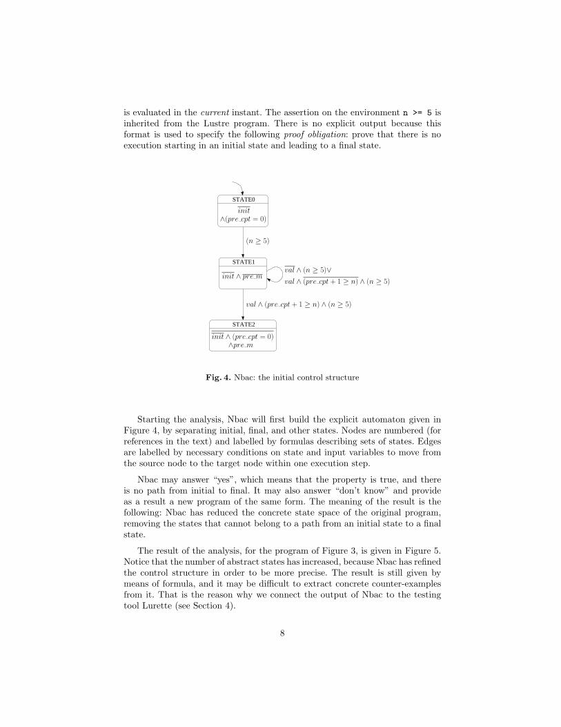
is evaluated in the current instant. The assertion on the environment n >= 5 isinherited from the Lustre program. There is no explicit output because thisformat is used to specify the following proof obligation: prove that there is noexecution starting in an initial state and leading to a final state.
STATE1
STATE0
STATE2
(n ≥ 5)
val ∧ (pre cpt + 1 ≥ n) ∧ (n ≥ 5)
val ∧ (n ≥ 5)∨val ∧ (pre cpt + 1 ≥ n) ∧ (n ≥ 5)
init ∧ pre m
init∧(pre cpt = 0)
init ∧ (pre cpt = 0)∧pre m
Fig. 4. Nbac: the initial control structure
Starting the analysis, Nbac will first build the explicit automaton given inFigure 4, by separating initial, final, and other states. Nodes are numbered (forreferences in the text) and labelled by formulas describing sets of states. Edgesare labelled by necessary conditions on state and input variables to move fromthe source node to the target node within one execution step.
Nbac may answer “yes”, which means that the property is true, and thereis no path from initial to final. It may also answer “don’t know” and provideas a result a new program of the same form. The meaning of the result is thefollowing: Nbac has reduced the concrete state space of the original program,removing the states that cannot belong to a path from an initial state to a finalstate.
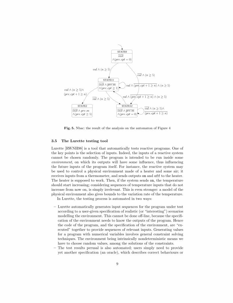
The result of the analysis, for the program of Figure 3, is given in Figure 5.Notice that the number of abstract states has increased, because Nbac has refinedthe control structure in order to be more precise. The result is still given bymeans of formula, and it may be difficult to extract concrete counter-examplesfrom it. That is the reason why we connect the output of Nbac to the testingtool Lurette (see Section 4).
Fig. 5. Nbac: the result of the analysis on the automaton of Figure 4
3.5 The Lurette testing tool
Lurette [RWNH98] is a tool that automatically tests reactive programs. One ofthe key points is the selection of inputs. Indeed, the inputs of a reactive systemcannot be chosen randomly. The program is intended to be run inside someenvironment, on which its outputs will have some influence, thus influencingthe future inputs of the program itself. For instance, the reactive system maybe used to control a physical environment made of a heater and some air; itreceives inputs from a thermometer, and sends outputs on and off to the heater.The heater is supposed to work. Then, if the system sends on, the temperatureshould start increasing; considering sequences of temperature inputs that do notincrease from now on, is simply irrelevant. This is even stronger: a model of thephysical environment also gives bounds to the variation rate of the temperature.
In Lurette, the testing process is automated in two ways:
– Lurette automatically generates input sequences for the program under testaccording to a user-given specification of realistic (or “interesting”) scenariosmodelling the environment. This cannot be done off-line, because the specifi-cation of the environment needs to know the outputs of the program. Hencethe code of the program, and the specification of the environment, are “ex-ecuted” together to provide sequences of relevant inputs. Generating valuesfor a program with numerical variables involves general constraint solvingtechniques. The environment being intrinsically nondeterministic means wehave to choose random values, among the solutions of the constraints.
– The test results perusal is also automated; users simply need to provideyet another specification (an oracle), which describes correct behaviours or
9
desired properties of the inputs and outputs sequences. The oracle is alsoexecuted together with the program and the environment.
Recently, Lurette has been completely re-implemented, and extended. Themain difference, from the user point of view, is the language used to describe theenvironment. In the first version of Lurette, only Lustre observers are offered,which means that we describe acceptors of correct input/output sequences, asLustre programs. In the new version of Lurette, one may also use the languageLutin [RR02]. Lutin is based on regular expressions, which are sometimes moreconvenient than Lustre, when sequences of behaviours have to be described. Thisdoes not change the underlying synchronous computation model, but it gives amore “operational” style of description, in which non-determinism is explicit.
The interesting part, for using this new version Lurette in our context, is thepossibility to attach weights to the branches of choices, in regular expressions.For instance, in the expression e1 + e2, one may put a large weight on e1, anda smaller one on e2, meaning that the generator will select the first branch moreoften.
Lutin is compiled into the intermediate format Lucky [Jah03,RJR03] whichis basically the automaton form of Lutin regular expressions, with weights onthe transitions. A major advantage of having such an intermediate format witha straightforward semantics is that it eases the work for third-party tools toproduce code into, which is precisely what we do in Section 4.
The restrictions of Lutin/Lucky are: (1) the constraints on inputs, at a givenpoint of a sequence, may only depend on the past values of outputs (as in Lustre);and (2) numeric constraints should be linear. For instance, x + y > 3 can behandled, but not x2
1 + x22 > 2 nor log x1 + sin x2 > ex3 .
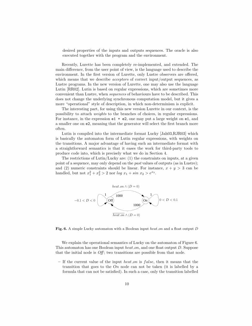
Off On
11 1000
1000
0 < D < 0.1−0.1 < D < 0
heat on ∧ (D = 0)
heat on ∧ (D = 0)
Fig. 6. A simple Lucky automaton with a Boolean input heat on and a float output D
We explain the operational semantics of Lucky on the automaton of Figure 6.This automaton has one Boolean input heat on, and one float output D. Supposethat the initial node is Off ; two transitions are possible from that node.
– If the current value of the input heat on is false, then it means that thetransition that goes to the On node can not be taken (it is labelled by aformula that can not be satisfied). In such a case, only the transition labelled
10
by the formula −0.1 < D < 0 can be taken. This formula will therefore besolved, and a solution will be drawn inside its set of solutions (namely, afloat between −0.1 and 0) which will be the output of the automaton for thefirst step.
– If the current value of the input heat on is true, then two transitions arepossible: the previous one, which has the weight 1; and a transition labelledby the weight 1000. The latter will therefore be drawn with a probabilityof 1000/1001. In such a case, since the transition is labelled by the formulaheat on ∧ D = 0, the value of the automaton output D will be 0 for thecurrent step. And at the next step, the current node will be On.
The behaviour is symmetric if the current node in On, except that D willincrease instead of decrease.
4 Connecting tools
From Ludic to Nbac. Consider again our Lustre program example of Figure 1,and the Nbac program of Figure 3. Remember that we want to generate aninput sequence that makes the output variable m become true, starting from agiven step of some execution (not necessarily the first instant). For that purpose,Ludic has to translate the Lustre program into the Nbac format, adding thespecification for the start and the goal states.
The start state we are interested in is unique and completely defined by thevaluation of the memories of the original program (init and pre cpt). Ludicencodes this state into the Nbac format with the variable start. The set of goalstates is usually specified as a safety property through the use of a synchronousobserver. In our example, we need an observer for the variable m. We are inter-ested in instants for which the output m is true. This is the same as looking forstates where pre(m) is true. This is encoded by goal = if start then falseelse pre m, because the goal should not be true at the instant in which we startthe analysis.
The encoding the original Lustre program requires only two variables:pre cpt for the memory of cpt, and init for the encoding of the arrow ini-tialisation operator. Specifying the final state involved in the proof obligationrequires one more variable: pre m, the memory of m. It is added to the Nbacprogram, with the obvious updating equation pre m’ = m.
For efficiency purposes, Ludic also performs some static slicing on the Lustreprogram, with respect to the set of variables involved in the definition of thegoal state. Moreover, the front-end of the Lustre compiler is used to performsome network minimisation in order to reduce the number of variables, a crucialissue for the performance of Nbac.
From Nbac to Lurette. The verification goal of Nbac is then asked to showthat there is no execution starting from the set of start states and leading tothe set of goal states. The two possible answers of the Nbac analysis are thefollowing:
11
– the property holds, i.e., the goal state is unreachable and has been removedduring the refinement of the control structure. For debugging purposes, thisinformation is as interesting as a counter-example;
– the property may not hold, i.e., there exists paths inside the control structureleading to the goal state. Lurette will try to generate one or more inputsequences. If Lurette generates at least one finite sequence, this sequencecan be replayed by Ludic. Otherwise, we are in the problematic case whereit is impossible to know, because of the abstractions made by Nbac, whetherthe state is unreachable or whether an existing path is difficult to reachbecause of a very low probability.
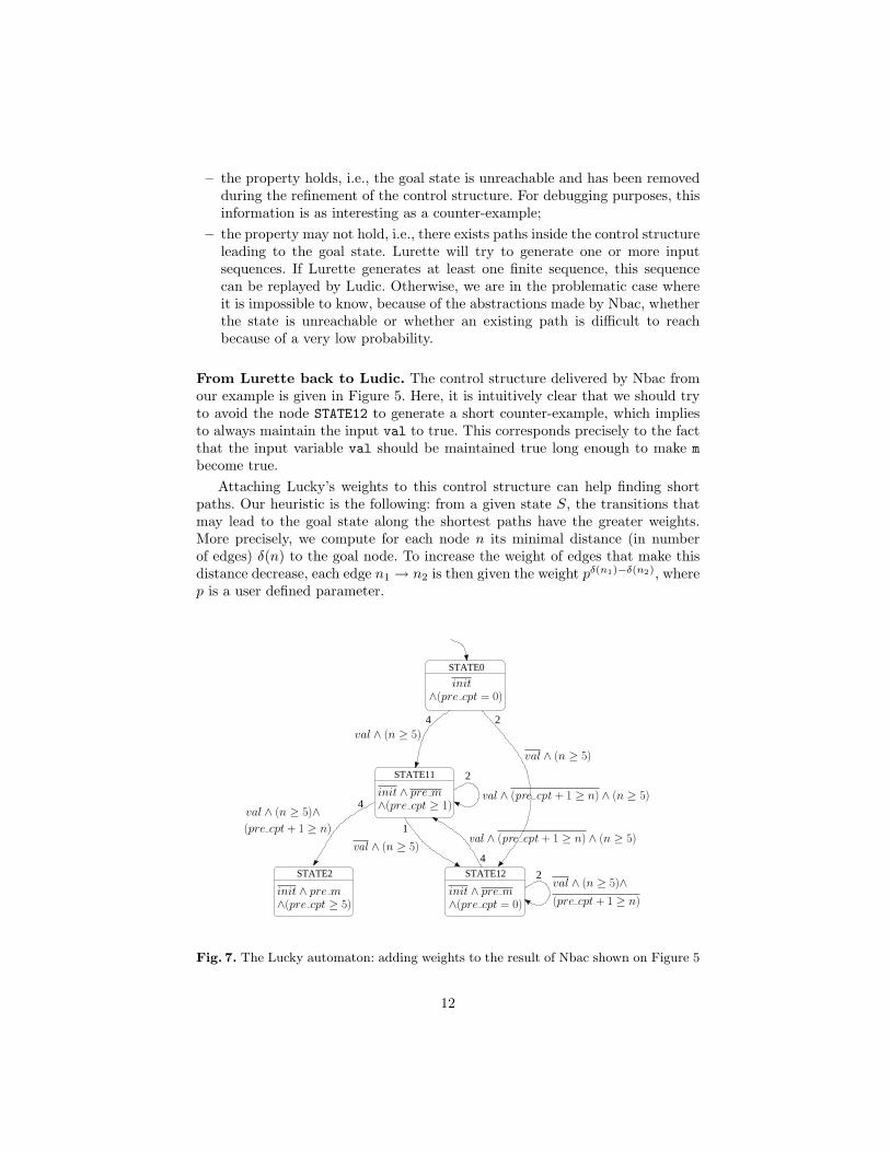
From Lurette back to Ludic. The control structure delivered by Nbac fromour example is given in Figure 5. Here, it is intuitively clear that we should tryto avoid the node STATE12 to generate a short counter-example, which impliesto always maintain the input val to true. This corresponds precisely to the factthat the input variable val should be maintained true long enough to make mbecome true.
Attaching Lucky’s weights to this control structure can help finding shortpaths. Our heuristic is the following: from a given state S, the transitions thatmay lead to the goal state along the shortest paths have the greater weights.More precisely, we compute for each node n its minimal distance (in numberof edges) δ(n) to the goal node. To increase the weight of edges that make thisdistance decrease, each edge n1 → n2 is then given the weight pδ(n1)−δ(n2), wherep is a user defined parameter.
Fig. 7. The Lucky automaton: adding weights to the result of Nbac shown on Figure 5
12
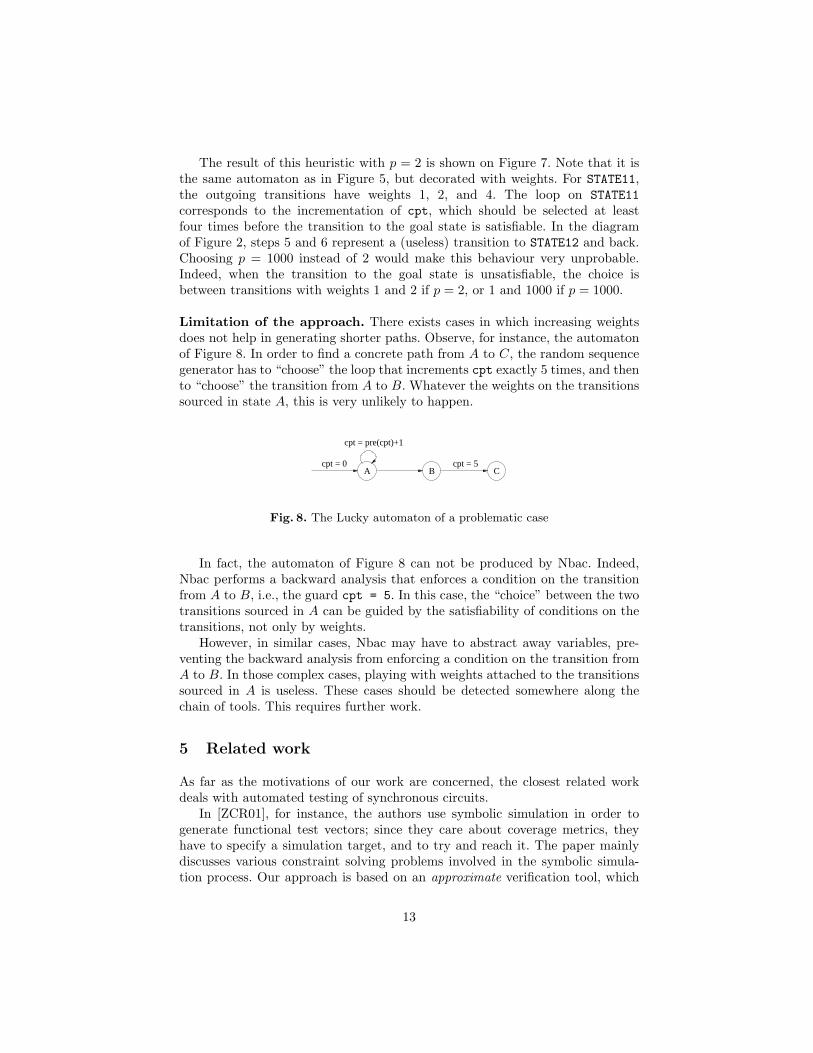
The result of this heuristic with p = 2 is shown on Figure 7. Note that it isthe same automaton as in Figure 5, but decorated with weights. For STATE11,the outgoing transitions have weights 1, 2, and 4. The loop on STATE11corresponds to the incrementation of cpt, which should be selected at leastfour times before the transition to the goal state is satisfiable. In the diagramof Figure 2, steps 5 and 6 represent a (useless) transition to STATE12 and back.Choosing p = 1000 instead of 2 would make this behaviour very unprobable.Indeed, when the transition to the goal state is unsatisfiable, the choice isbetween transitions with weights 1 and 2 if p = 2, or 1 and 1000 if p = 1000.
Limitation of the approach. There exists cases in which increasing weightsdoes not help in generating shorter paths. Observe, for instance, the automatonof Figure 8. In order to find a concrete path from A to C, the random sequencegenerator has to “choose” the loop that increments cpt exactly 5 times, and thento “choose” the transition from A to B. Whatever the weights on the transitionssourced in state A, this is very unlikely to happen.
CBA
cpt = pre(cpt)+1
cpt = 0 cpt = 5
Fig. 8. The Lucky automaton of a problematic case
In fact, the automaton of Figure 8 can not be produced by Nbac. Indeed,Nbac performs a backward analysis that enforces a condition on the transitionfrom A to B, i.e., the guard cpt = 5. In this case, the “choice” between the twotransitions sourced in A can be guided by the satisfiability of conditions on thetransitions, not only by weights.
However, in similar cases, Nbac may have to abstract away variables, pre-venting the backward analysis from enforcing a condition on the transition fromA to B. In those complex cases, playing with weights attached to the transitionssourced in A is useless. These cases should be detected somewhere along thechain of tools. This requires further work.
5 Related work
As far as the motivations of our work are concerned, the closest related workdeals with automated testing of synchronous circuits.
In [ZCR01], for instance, the authors use symbolic simulation in order togenerate functional test vectors; since they care about coverage metrics, theyhave to specify a simulation target, and to try and reach it. The paper mainlydiscusses various constraint solving problems involved in the symbolic simula-tion process. Our approach is based on an approximate verification tool, which
13
guarantees more reasonable costs. For the “reach a state” functionality to beuseful in a debugger, it should not take too long.
The connection between a proof tool and a test case generation tool is nota completely new idea: it has been done already, in order to obtain counter-examples when the Boolean model-checker fails [PHR01]. The problem of errordiagnosis in symbolic model-checking is well known [CGMZ95], but it is evenmore difficult in the case of programs with (a lot of) numerical variables, be-cause the verification tool only gives approximate results. More recently, therehas been interest in using counter-example generation to refine abstractions[CGJ+00,CCK+02], but in these works only abstraction of (big) finite-state sys-tems are considered, which simplifies several algorithmical aspects.
6 Conclusions and Further work
The first motivation of this work is to provide a “reach-a-state” functionalityin a debugger for reactive systems, written in formally defined languages, forwhich the problem can be expressed clearly. Since implementing this functional-ity amounts to solving a general model-checking problem, we chose a solution inwhich several independent tools are connected together, instead of some ad hoccoding of model-checking algorithms in the debugger. At first sight, it might notbe the most straightforward implementation, but it makes clear what interfaceshave to be respected between the various stages, for other tools to be used in thesame chain. The set of tools we selected for demonstrating the feasibility of theapproach have the following advantages: they all take numerical variables intoaccount; the proof tool favours approximate results because they can be obtainedin a reasonable time; the testing tool exploits the weights on the transitions ofthe automaton in order to provide short sequences.
We tried the chain of tools on medium-size examples, and it seems feasible.As one could expect, the bottleneck lies in the verification tool. In particular, thenumber of variables has a strong influence on the complexity of the algorithmsinvolved. Further work will be devoted to the translation from Ludic to theinput of Nbac, in order to simplify the program as much as possible. We alreadyused slicing techniques, but we could also apply general constant propagationtechniques, or other optimisations based on static analyses.
Further work includes studying carefully the influence of weights on the gen-eration of “short” sequences. For the moment, the weights are chosen automati-cally according to the structure of the graph, and the length of the paths leadingto the goal. We could think of alternative criteria for choosing the sequences: ina debugger, the sequence provided by our chain of tools is meant to show clearlyhow the program can go from the present state to another one. It might be thecase that a sequence in which a minimal number of variables change their valueis simpler to understand than a shortest sequence in which all variables changetheir value at each step.
As a new feature in the debugger Ludic, the ability to reach a state auto-matically has several applications. In order to automate the exploration of both
14
time and data dependencies of complex programs, Ludic implements an orig-inal adaptation of the well-known algorithmic debugging principle [Sha83]. Inpractice, this technique can be used for a large class of (even big) programs.However, it may be the case that, at a given point of some execution, the valueof a variable directly depends on some values computed many steps ago, forcingthe tool to explore many previous steps (potentially the whole execution). Forsuch programs, generating a short input sequence that leads to the same statewhere the bug symptom originally occurred would help locating the bug.
References
[Ack78] S. B. Ackers. Binary decision diagrams. In IEEE Transactions on Comput-ers, pages 509–516, 1978.
[BG92] G. Berry and G. Gonthier. The Esterel synchronous programming language:Design, semantics, implementation. Science Of Computer Programming,19(2):87–152, 1992.
[Bry86] R. E. Bryant. Graph-based algorithms for Boolean function manipulation.IEEE Transactions on Computers, C-35(8):677–691, August 1986.
[CC77] P. Cousot and R. Cousot. Abstract interpretation: a unified lattice model forstatic analysis of programs by construction or approximation of fixpoints. In4th ACM Symposium on Principles of Programming Languages, POPL’77,Los Angeles, January 1977.
[CCK+02] P. Chauhan, E. Clarke, J. Kukula, S. Sapra, H. Veith, and D. Wang. Au-tomated abstraction refinement for model checking large state spaces usingsat based conflict analysis. In Formal Methods in Computer Aided Design(FMCAD’02), page 18, November 2002. Paper will appear in the FMCAD2002 conference.
[CES86] E. M. Clarke, E. A. Emerson, and A. P. Sistla. Automatic verification offinite-state concurrent systems using temporal logic specifications. ACMTOPLAS, 8(2), 1986.
[CGJ+00] E. Clarke, O. Grumberg, S. Jha, Y. Lu, and H. Veith. Counterexample-guided abstraction refinement. In Computer Aided Verification, CAV’00,volume 1855 of LNCS, July 2000.
[CGMZ95] E. M. Clarke, O. Grumberg, K. L. McMillan, and X. Zhao. Efficient gen-eration of counterexamples and witnesses in symbolic model checking. InProceedings of the 32nd ACM/IEEE conference on Design automation con-ference, pages 427–432. ACM Press, 1995.
[CH78] P. Cousot and N. Halbwachs. Automatic discovery of linear restraintsamong variables of a program. In 5th ACM Symposium on Principles ofProgramming Languages, POPL’78, Tucson (Arizona), January 1978.
[Gau03] F. Gaucher. Slicing lustre programs. Technical report, VERIMAG, Greno-ble, February 2003.
[Hal93] N. Halbwachs. Synchronous programming of reactive systems. Kluwer Aca-demic Pub., 1993.
[HCRP91] N. Halbwachs, P. Caspi, P. Raymond, and D. Pilaud. The syn-chronous dataflow programming language lustre. Proceedings of the IEEE,79(9):1305–1320, September 1991.
15
[HLR93] N. Halbwachs, F. Lagnier, and P. Raymond. Synchronous observers andthe verification of reactive systems. In M. Nivat, C. Rattray, T. Rus, andG. Scollo, editors, Third Int. Conf. on Algebraic Methodology and Soft-ware Technology, AMAST’93, Twente, June 1993. Workshops in Comput-ing, Springer Verlag.
[HWKF02] S. Hazelhurst, O. Weissberg, G. Kamhi, and L. Fix. A hybrid verificationapproach: Getting deep into the design. In DAC, New Orleans, Louisiana,June 2002. ACM.
[Jah03] E. Jahier. The Lucky Reference Manual Release 0.2, 2003.[Jea00] B. Jeannet. Dynamic partitioning in linear relation analysis. Technical Re-
port RS-00-38, BRICS, December 2000. http://www.brics.dk/RS/00/38,to appear in Formal Methods and System Design.
[Jea02] B. Jeannet. The Polka Convex Polyhedra library Edition 2.0. IRISA, May2002. www.irisa.fr/prive/bjeannet/newpolka.html.
[JHR99] B. Jeannet, N. Halbwachs, and P. Raymond. Dynamic partitioning in anal-yses of numerical properties. In A. Cortesi and G. File, editors, StaticAnalysis Symposium, SAS’99, Venice (Italy), September 1999. LNCS 1694,Springer Verlag.
[Lam77] L. Lamport. Proving the correctness of multiprocess programs. IEEETransactions on Software Engineering, SE-3(2):125–143, 1977.
[LGLL91] P. LeGuernic, T. Gautier, M. LeBorgne, and C. LeMaire. Programming realtime applications with signal. Proceedings of the IEEE, 79(9):1321–1336,September 1991.
[MG00] F. Maraninchi and F. Gaucher. Step-wise + algorithmic debugging forreactive programs: Ludic, a debugger for lustre. In AADEBUG’2000 –Fourth International Workshop on Automated Debugging, Munich, August2000.
[PHR01] G. Pace, N. Halbwachs, and P. Raymond. Counter-example generationin symbolic abstract model-checking. In 6th International Workshop onFormal Methods for Industrial Critical Systems, FMICS’2001, Paris, July2001. Inria.
[QS82] J. P. Queille and J. Sifakis. Specification and verification of concurrentsystems in cesar. In International Symposium on Programming. LNCS 137,Springer Verlag, April 1982.
[RJR03] P. Raymond, E. Jahier, and Y. Roux. Weight-labelled transition systems:an operational model for stochastic reactive systems. submitted for publi-cation, January 2003.
[RR02] P. Raymond and Y. Roux. Describing non-deterministic reactive systemsby means of regular expressions. In First Workshop on Synchronous Lan-guages, Applications and Programming, SLAP’02, Grenoble, April 2002.
[RWNH98] P. Raymond, D. Weber, X. Nicollin, and N. Halbwachs. Automatic testingof reactive systems. In 19th IEEE Real-Time Systems Symposium, Madrid,Spain, December 1998.
[Sha83] E.Y. Shapiro. Algorithmic program debugging. MIT Press, 1983.[Wei79] Mark Weiser. Program slices: Formal, psychological, and practical investi-
gations of an automatic program abstraction method. PhD thesis, Universityof Michigan, Ann Arbor, MI, 1979.
[ZCR01] Z. Zeng, M. Ciesielski, and B. Rouzeyre. Functional test generation usingconstraint logic programming. In 11th IFIP International Conf. on VLSI-SOC. LNCS 137, Springer Verlag, December 2001.
16
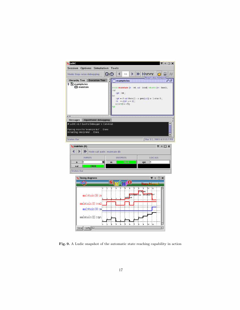
Fig. 9. A Ludic snapshot of the automatic state reaching capability in action


![Debugging with gdb · Debugging Data Race Conditions: Section 12.2 [Data Race Detection], page 171. Debugging OpenMP*: Section 12.4 [OpenMP* Debugging], page 177. Extended recording](https://static.documents.pub/doc/80x56/5f0b5c707e708231d4302334/debugging-with-gdb-debugging-data-race-conditions-section-122-data-race-detection.jpg)


