Automatic temperature controlled fan allow you to experience total freedom by eliminating manual operations for cooling a system during a process. The temperature of all types of machines used in an industry will increase due to its continues working. It is necessary to cool the machines for their long life and better working. Automatic temperature controlled fan will cool the surroundings according to the surrounding temperature.
27
Automatic temperature controlled fan Dept. ECE, CEMP 1 CHAPTER 1 INTRODUCTION 1.1 AUTOMATIC CONTROL In the fast-paced world, there is little time for every processes and greater need for automatically operating systems. The idea for an Automatic temperature controlled fan stems from this need. Automatic temperature controlled fan allow you to experience total freedom by eliminating manual operations for cooling a system during a process. The temperature of all types of machines used in an industry will increase due to its continues working. It is necessary to cool the machines for their long life and better working. Automatic temperature controlled fan will cool the surroundings according to the surrounding temperature. 1.2 WHAT IS AUTOMATIC TEMPERATURE CONTROLLED FAN? Automatic temperature controlled fan is a device, that can be used for cooling the surroundings of a machine or room automatically with the changes in the temperature of the surroundings. It uses a thermister for sensing the temperature and a fan for providing cooling. When the temperature is raised above a fixed point the device automatically switch on the fan and there by reduces the temperature. It is an efficient device that can be used for cooling purposes of the machines in an industry. It can also be used with ceiling fans in a house for cooling a room automatically according to the temperature.
Transcript
Automatic temperature controlled fan
Dept. ECE, CEMP
1
CHAPTER 1
INTRODUCTION
1.1 AUTOMATIC CONTROL
In the fast-paced world, there is little time for every processes and greater need
for automatically operating systems. The idea for an Automatic temperature controlled
fan stems from this need.
Automatic temperature controlled fan allow you to experience total freedom by
eliminating manual operations for cooling a system during a process. The temperature
of all types of machines used in an industry will increase due to its continues working.
It is necessary to cool the machines for their long life and better working.
Automatic temperature controlled fan will cool the surroundings according to
the surrounding temperature.
1.2 WHAT IS AUTOMATIC TEMPERATURE CONTROLLED FAN?
Automatic temperature controlled fan is a device, that can be used for cooling the
surroundings of a machine or room automatically with the changes in the temperature of
the surroundings.
It uses a thermister for sensing the temperature and a fan for providing cooling. When the
temperature is raised above a fixed point the device automatically switch on the fan and
there by reduces the temperature.
It is an efficient device that can be used for cooling purposes of the machines in an
industry. It can also be used with ceiling fans in a house for cooling a room automatically
according to the temperature.
Automatic temperature controlled fan
Dept. ECE, CEMP
2
1.2.2 ADVANTAGES OF AUTOMATIC TEMPERATURE CONTROLLED FAN
1. Simple and easy to construct.
2. Low cost.
3. Fully automatic.
4. Can be used for a number of applications.
5. Besides, since an optocoupler is used, the control circuit is fully isolated from
power circuit, thus providing added safety.
6. For any given temperature the speed of fan can be adjusted to a desired value.
Automatic temperature controlled fan
Dept. ECE, CEMP
3
CHAPTER 2
BLOCK DIAGRAM
Temperature
sensor
Current to
Voltage
converter
amplification
comparator
Load
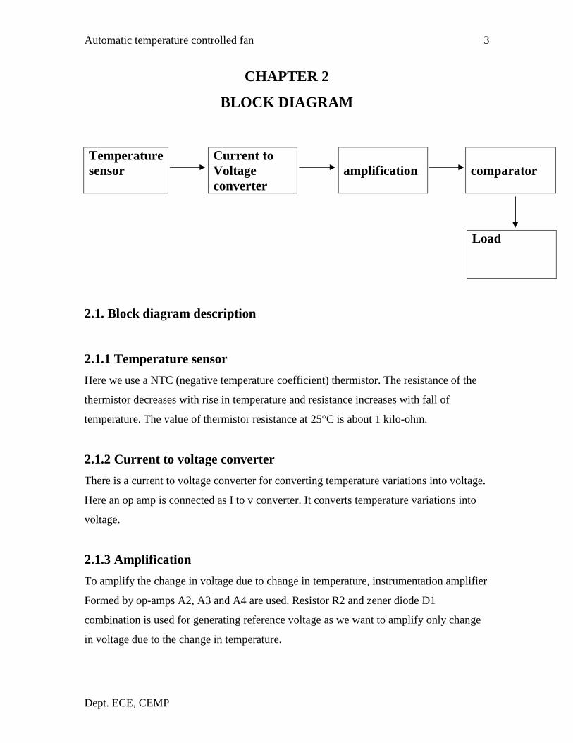
2.1. Block diagram description
2.1.1 Temperature sensor
Here we use a NTC (negative temperature coefficient) thermistor. The resistance of the
thermistor decreases with rise in temperature and resistance increases with fall of
temperature. The value of thermistor resistance at 25°C is about 1 kilo-ohm.
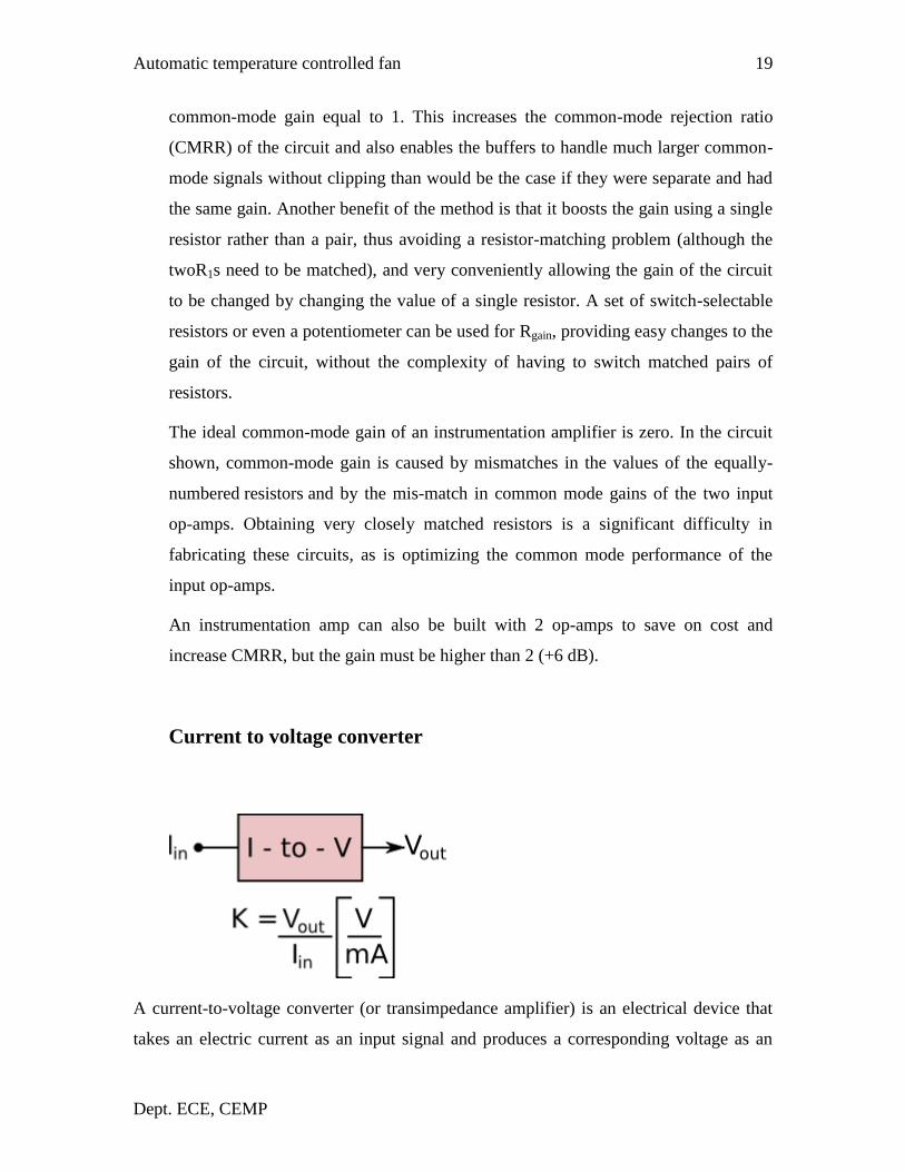
2.1.2 Current to voltage converter
There is a current to voltage converter for converting temperature variations into voltage.
Here an op amp is connected as I to v converter. It converts temperature variations into
voltage.
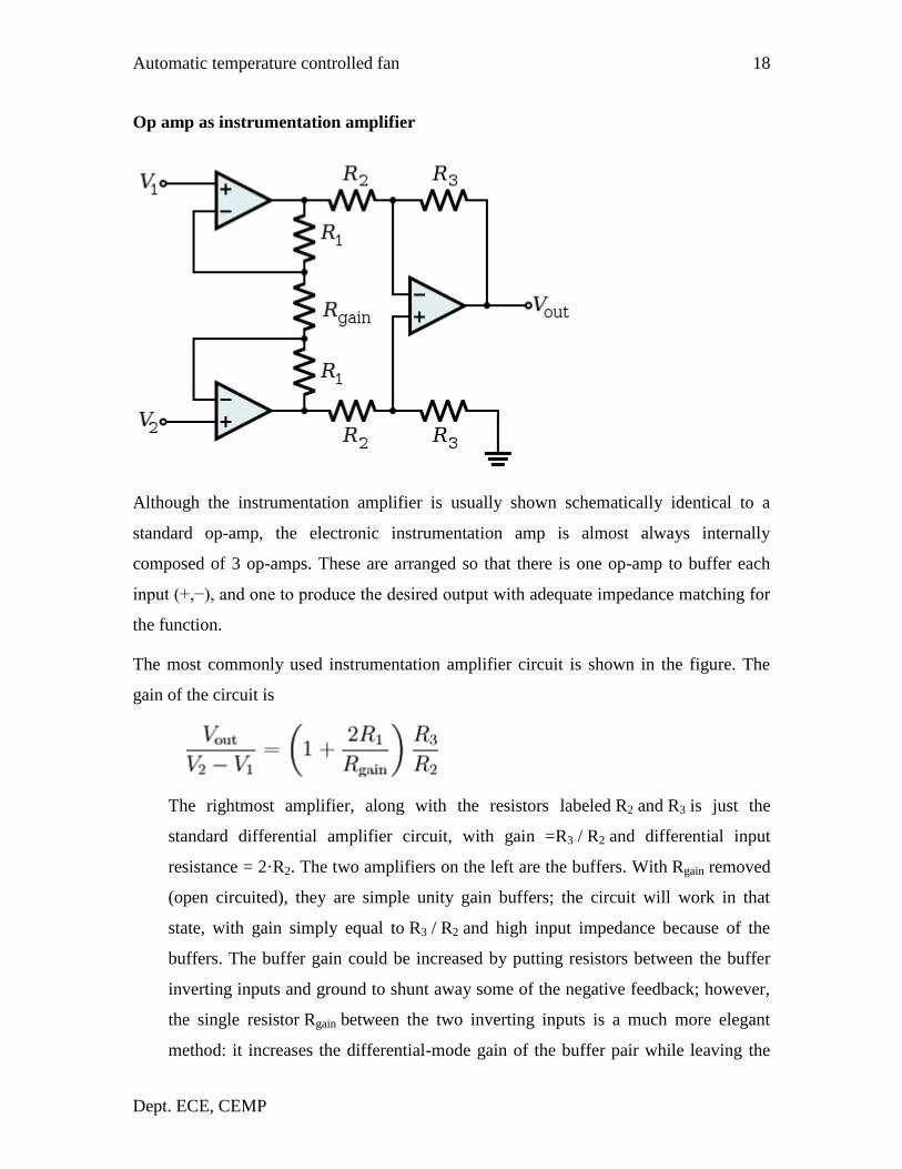
2.1.3 Amplification
To amplify the change in voltage due to change in temperature, instrumentation amplifier
Formed by op-amps A2, A3 and A4 are used. Resistor R2 and zener diode D1
combination is used for generating reference voltage as we want to amplify only change
in voltage due to the change in temperature.
Automatic temperature controlled fan
Dept. ECE, CEMP
4
2.1.4 Comparator
Op-amp μA741 (IC2) works as a comparator. One input to the comparator is the output
from the instrumentation amplifier while the other input is the stepped down, rectified
and suitably attenuated sample of AC voltage. This is a negative going pulsating DC
voltage. Comparator compares the two inputs to give output.
Automatic temperature controlled fan
Dept. ECE, CEMP
5
2.1.5Load
The output from the comparator is coupled to an optocoupler, which in turn controls the
AC power delivered to fan (load).
Automatic temperature controlled fan
Dept. ECE, CEMP
6
CHAPTER 3
AUTOMATIC TEMPERATURE CONTROLLED FAN
3.1 POWER SUPPLY
3.1.1 TRANSFORMER
In brief a transformer is device that
Transfers electric power from one circuit to another
Does so without any change of frequency
Accomplishes this by electromagnetic induction
Contains to electric circuits which are linked by mutual induction
The power supply for this project requires a step-down transformer with 250 V and
output with +12 V&-12V.
3.1.2 RECTIFIER
The rectifier circuit is the heart of a power supply. We use full wave bridge rectifier. The
description is as follows
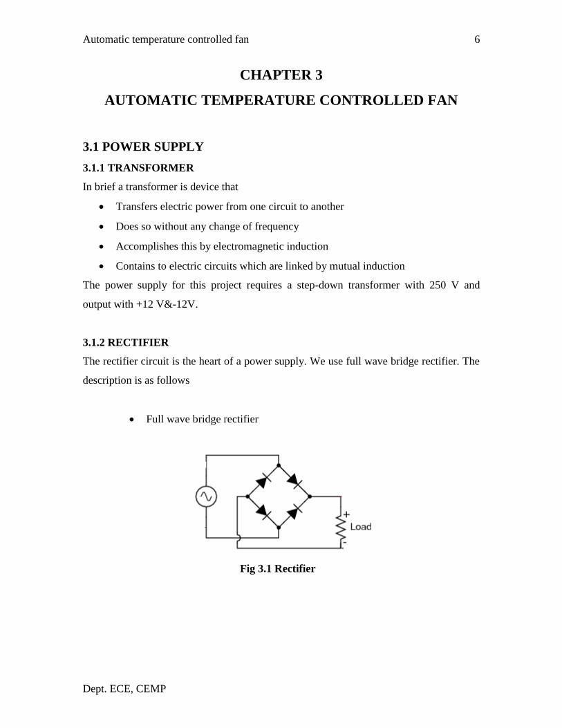
Full wave bridge rectifier
Fig 3.1 Rectifier
Automatic temperature controlled fan
Dept. ECE, CEMP
7
During the positive half cycles of the secondary voltage diodes D2 and D4 are
conducting and diodes D1 and D3 not conducting. Therefore, current flows through the
secondary winding, diode D2, load resister RL and D4. During the negative half cycles
D1 and D3 are conducting and diodes D2 and D4 are not conducting. Therefore, current
flows through the secondary winding, diode D1, load resistor RL and diode D3.In both
cases, the current passes through the load resistor in the same direction. The rectifier used
in this project is bridge rectifier.
3.1.3 FILTER
The rectifier used in this problem is shunt capacitor filter. A filter circuit is a device
which removes the ac component of rectifiers output but allows the dc component to
reach the load.
The filter circuit should be installed between the rectifier and the load. A filter
circuit is generally a combination of inductor (L) and capacitor (C). The filtering action
of inductor and capacitor depends upon the basic electrical principles. A capacitor passes
ac readily but does not pass dc at all. On the other hand the inductor opposes ac but
allows dc to pass through it. It then becomes clear that suitable network of inductor and
capacitor can effectively remove the ac component to reach the load.
3.1.4 VOLTAGE REGULATORS
A voltage stabilizer is an electronic circuit that supplies a constant voltage regardless
of changes in load current, temperature, and AC line voltage. Although voltage regulators
can be designed using op-amps, it is quicker and easier to use IC Voltage regulators.
In this project a 12V supply is needed. For this first a step down transformer with
rating 230/12-0,500mA is used. The stepped down voltage is rectified using a bridge
rectifier making use of four 1N4007 diodes. The output of the rectifier is filtered using a
capacitive filter. Then the output is given to a voltage regulator IC 7812 to produce a 12V
output.
Automatic temperature controlled fan
Dept. ECE, CEMP
8
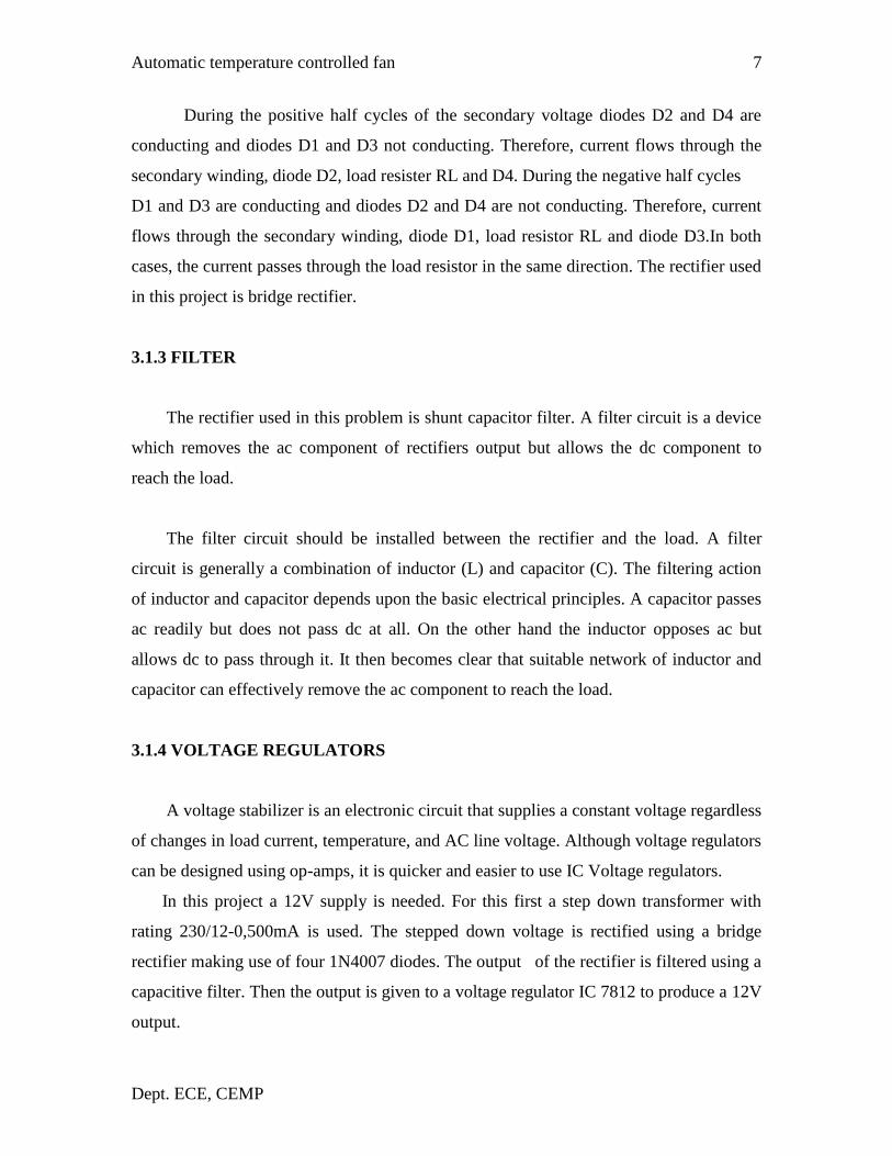
Regulator IC (LM 7812)
The LM7812 monolithic 3-terminal positive voltage regulators. They are intended as
fixed voltage regulators in a wide range of applications. In addition to use as fixed
voltage regulators, these devices can be used with external components to obtain
adjustable output voltages and currents. Considerable effort was expended to make the
entire series of regulators easy to use and minimize the number of external components.
Fig 3.2 LM 7812
Automatic temperature controlled fan
Dept. ECE, CEMP
9
3.2 CIRCUIT DIAGRAM OF AUTOMATIC TEMPERATURE
CONTROLLED FAN &IT’S EXPLANATION
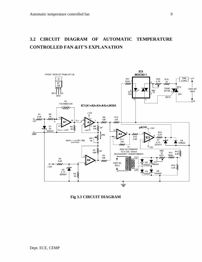
Fig 3.3 CIRCUIT DIAGRAM
Automatic temperature controlled fan
Dept. ECE, CEMP
10
In this circuit, the temperature sensor used is an NTC thermistor, i.e. one having a
negative temperature coefficient. The value of thermistor resistance at 25°C is about 1
kilo-ohm. Op-amp A1 essentially works as I to V (current-to-voltage) converter and
converts temperature variations into voltage variations. To amplify the change in voltage
due to change in temperature, instrumentation amplifier formed by op-amps A2, A3 and
A4 Misused. Resistor R2 and zener diode D1 combination is used for generating
reference voltage as we want to amplify only change in voltage due to the
change in temperature.
Op-amp μA741 (IC2) works as a comparator. One input to the comparator is the output
from the instrumentation amplifier while the other input is the stepped down, rectified
and suitably attenuated sample of AC voltage. This is a negative going pulsating DC
voltage. It will be observed that with increase in temperature, pin 2 of IC2 goes more and
more negative and hence the width of the positive going output pulses (at pin 6) increases
linearly with the temperature. Thus IC2 functions as a pulse width modulator in this
circuit. The output from the comparator is coupled to an optocoupler, which in turn
controls the AC power delivered to fan (load).The circuit has a high sensitivity and
The output RMS voltage (across load) can be varied from 120V to 230V (for a
temp.range of 22°C to 36°C), and hence wide variations in speed are available. Also note
that speed varies linearly and not in steps. Besides, since an optocoupler is used, the
control circuit is fully isolated from power circuit, thus providing added safety. Note that
for any given temperature the speed of fan (i.e. voltage across load) can be adjusted to a
desired value by adjusting potentiometer.
3.3 COMPONENTS
3.3.1 RESISTOR
A resistor is a two-terminal passive electronic component which implements
electrical resistance as a circuit element. When a voltage V is applied across the terminals
of a resistor, a current I will flow through the resistor in direct proportion to that voltage.
The reciprocal of the constant of proportionality is known as the resistance R, since, with
Automatic temperature controlled fan
Dept. ECE, CEMP
11
a given voltage V, a larger value of R further "resists" the flow of current I as given by
Ohm's law
I = V/R
The ohm (symbol: Ω) is the SI unit of electrical resistance, named after George
Simon Ohm. An ohm is equivalent to a volt per ampere. Since resistors are specified and
manufactured over a very large range of values, the derived units of milliohm (1 mΩ =
10−3
Ω), kilohm (1 kΩ = 103 Ω), and megohm (1 MΩ = 10
6 Ω) are also in common usage.
3.3.2 CAPACITORS
A capacitor (formerly known as condenser) is a device for storing electric
charge. The forms of practical capacitors vary widely, but all contain at least two
conductors separated by a non-conductor. Capacitors used as parts of electrical systems,
for example, consist of metal foils separated by a layer of insulating film.
Capacitors are widely used in electronic circuits for blocking direct current while
allowing alternating current to pass, in filter networks, for smoothing the output of power
supplies, in the resonant circuits that tune radios to particular frequencies and for many
other purposes.
A capacitor is a passive electronic component consisting of a pair of conductors
separated by a dielectric (insulator). When there is a potential difference (voltage) across
the conductors, a static electric field develops in the dielectric that stores energy and
produces a mechanical force between the conductors. An ideal capacitor is characterized
by a single constant value, capacitance, measured in farads. This is the ratio of the
electric charge on each conductor to the potential difference between them.
Automatic temperature controlled fan
Dept. ECE, CEMP
12
3.3.3VARIABLE RESISTOR (PRESET)
This type of variable resistor (a preset) is operated with a small
screwdriver or similar tool. It is designed to be set when the circuit is
made and then left without further adjustment. Presets are cheaper than
normal variable resistors so they are often used in projects to reduce
the cost.
Fig 3.6 Variable Resistor
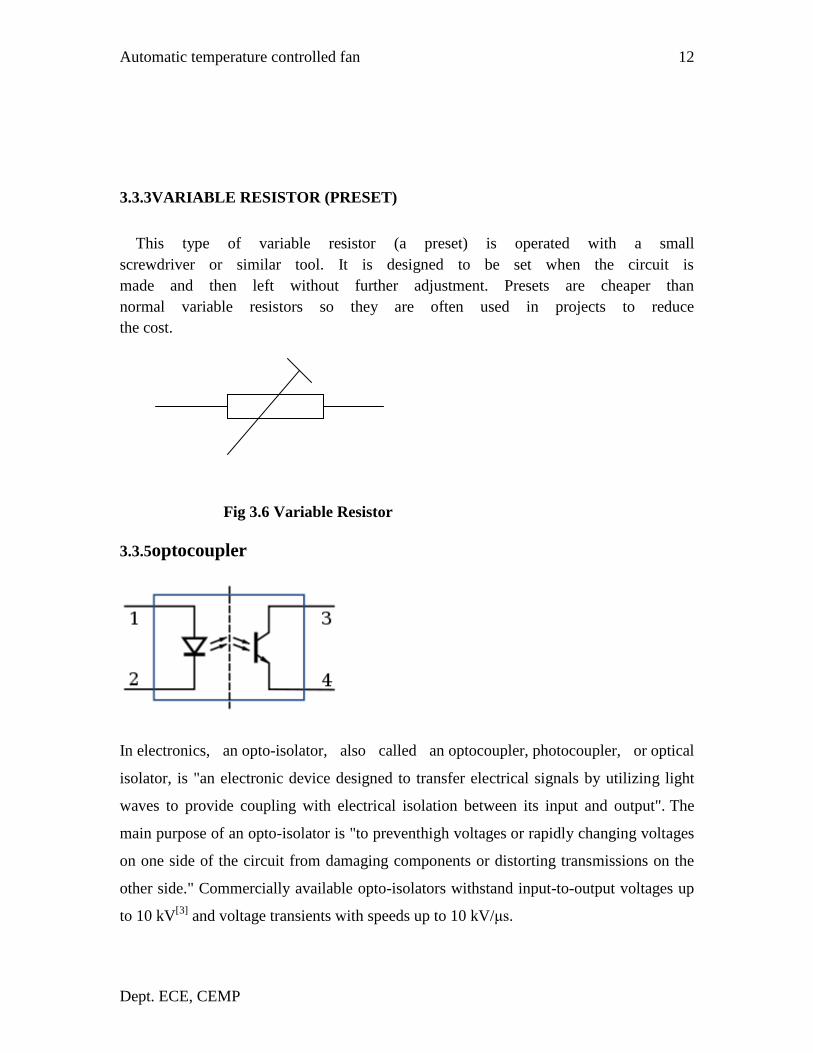
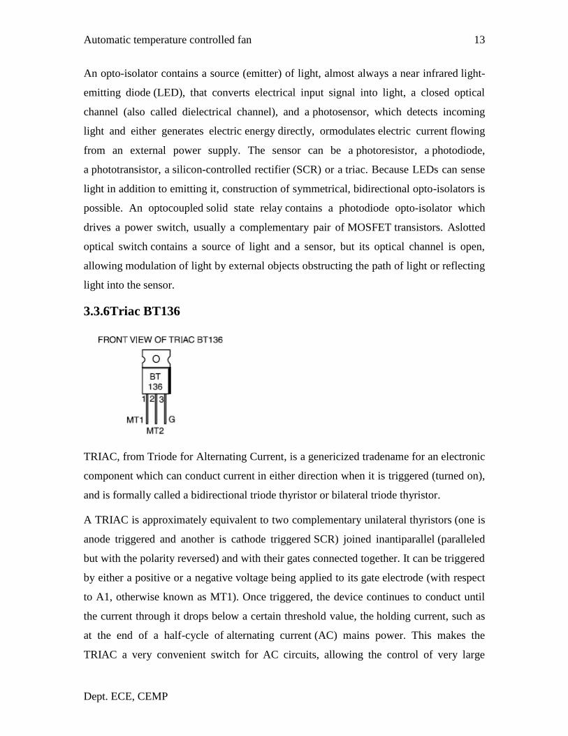
3.3.5optocoupler
In electronics, an opto-isolator, also called an optocoupler, photocoupler, or optical
isolator, is "an electronic device designed to transfer electrical signals by utilizing light
waves to provide coupling with electrical isolation between its input and output". The
main purpose of an opto-isolator is "to preventhigh voltages or rapidly changing voltages
on one side of the circuit from damaging components or distorting transmissions on the
other side." Commercially available opto-isolators withstand input-to-output voltages up
to 10 kV[3]
and voltage transients with speeds up to 10 kV/μs.