Automatic Welding System for Crawler Crane Top and Bottom Booms Akira OKAMOTO *1 , Masatoshi HIDA *1 , Tsutomu OONE *1 , Takemasa YAMASAKI *1 , Tatsuro ASANO *2 , Toshifumi KOBAYASHI *2 *1 Production Systems Research Laboratory, Technical Development Group *2 KOBELCO CRANES CO., LTD. An automatic welding system for upper and lower booms was developed at KOBELCO CRANES CO., LTD., aiming at stabilizing production capacity, achieving consistently high quality and increasing flexibility for varying work volumes. A technology was developed for reducing the man-hours spent in teaching tasks having to do with the weld lines of lattice pipes. Also developed was a sensor technology that enables copy welding by reliably detecting welding lines even during large-current welding, which generates large amounts of fume and spatter, and during welding on a specular reflection surface. This paper introduces these technologies. Introduction As the crane manufacturing business continues to globalize, our factory in Japan is required to function as a mother in pursuing world-class productivity (e.g., personnel saving) and quality, as well as to respond flexibly to varying work volumes. Our overseas factories, on the other hand, need, for example, to ensure welding quality as high as that achieved by the mother factory without relying on skilled welding experts. In response to these requirements, Kobe Steel has worked to automate the process of welding lattice booms (i.e., insert booms, top booms and bottom booms), a process which has relied on the advanced skills of welding experts. Among these booms, the welding of the insert booms has been automated and implemented. 1)-4) The top and bottom booms, however, have a greater number of joints than the insert booms and have many problems of their own, such as increased robot-teaching time. Now, Kobe Steel has overcome these problems and automated the welding of top and bottom booms. This paper gives an outline of that achievement. 1. Problems in automating welding process for lattice-booms The booms of crawler cranes have structures as shown in Fig. 1, in which pipes are arranged in lattices. (Such booms are hereinafter referred to as "lattice booms.") A crawler-crane boom generally consists of component booms that are roughly classified into 3 types: namely a top boom, bottom boom and insert boom. The welding of a component consisting of pipes arranged in lattice structures involves welding joints, each of which consists of pipes with different wall thicknesses and has a saddle-shaped welding line whose direction continuously fluctuates between upward and downward. Therefore, the torch posture and electrode manipulation during welding must be controlled such that these saddle-shaped lines are copied, which requires high-level skills. During the automatic welding of these lattice booms , long booms are subjected to thermal strain, and assembly errors occur. This renders indispensable a copy welding in which the groove positions of welded portions are continuously detected. A pipe-to-pipe joint with a complex saddle shape causes its contour to change continuously, which makes it difficult to use the conventional function of arc copying. As for insert booms, Kobe Steel has developed a unique logic for detecting the weld lines in lattice pipe joints to realize the copying function. As shown in Fig. 2 (right) , this logic has been combined with commercially available hardware having a welding range sensor to realize automatic welding. This automatic welding has been implemented in real machines. An insert boom of interest has a parallel structure in which a joint shape with the same crossing angle is repeated. All of its joints are pipe-to-pipe joins. Therefore, as shown in Fig. 2 (left), the total number of objects for Fig. 1 Construction of booms for crawler crane KOBELCO TECHNOLOGY REVIEW NO. 33 FEB. 2015 61
Transcript
Automatic Welding System for Crawler Crane Top and Bottom BoomsAkira OKAMOTO*1, Masatoshi HIDA*1, Tsutomu OONE*1, Takemasa YAMASAKI*1, Tatsuro ASANO*2, Toshifumi KOBAYASHI*2
*1 Production Systems Research Laboratory, Technical Development Group*2 KOBELCO CRANES CO., LTD.
An automatic welding system for upper and lower booms was developed at KOBELCO CRANES CO., LTD., aiming at stabilizing production capacity, achieving consistently high quality and increasing flexibility for varying work volumes. A technology was developed for reducing the man-hours spent in teaching tasks having to do with the weld lines of lattice pipes. Also developed was a sensor technology that enables copy welding by reliably detecting welding lines even during large-current welding, which generates large amounts of fume and spatter, and during welding on a specular reflection surface. This paper introduces these technologies.
Introduction
As the crane manufacturing business continues to globalize, our factory in Japan is required to function as a mother in pursuing world-class productivity (e.g., personnel saving) and quality, as well as to respond flexibly to varying work volumes. Our overseas factories, on the other hand, need, for example, to ensure welding quality as high as that achieved by the mother factory without relying on skilled welding experts. In response to these requirements, Kobe Steel has worked to automate the process of welding lattice booms (i.e., insert booms, top booms and bottom booms), a process which has relied on the advanced skills of welding experts. Among these booms, the welding of the insert booms has been automated and implemented.1)-4) The top and bottom booms, however, have a greater number of joints than the insert booms and have many problems of their own, such as increased robot-teaching time. Now, Kobe Steel has overcome these problems and automated the welding of top and bottom booms. This paper gives an outline of that achievement.
1. Problems in automating welding process for lattice-booms
The booms of crawler cranes have structures as shown in Fig. 1, in which pipes are arranged in lattices. (Such booms are hereinafter referred to as "lattice booms.") A crawler-crane boom generally consists of component booms that are roughly classified into 3 types: namely a top boom,
bottom boom and insert boom. The welding of a component consisting of pipes arranged in lattice structures involves welding joints, each of which consists of pipes with different wall thicknesses and has a saddle-shaped welding line whose direction continuously fluctuates between upward and downward. Therefore, the torch posture and electrode manipulation during welding must be controlled such that these saddle-shaped lines are copied, which requires high-level skills. During the automatic welding of these lattice booms, long booms are subjected to thermal strain, and assembly errors occur. This renders indispensable a copy welding in which the groove positions of welded portions are continuously detected. A pipe-to-pipe joint with a complex saddle shape causes its contour to change continuously, which makes it difficult to use the conventional function of arc copying. As for insert booms, Kobe Steel has developed a unique logic for detecting the weld lines in lattice pipe joints to realize the copying function. As shown in Fig. 2 (right), this logic has been combined with commercially available hardware having a welding range sensor to realize automatic welding. This automatic welding has been implemented in real machines. An insert boom of interest has a parallel structure in which a joint shape with the same crossing angle is repeated. All of its joints are pipe-to-pipe joins. Therefore, as shown in Fig. 2 (left), the total number of objects for
Fig. 1 Construction of booms for crawler crane
KOBELCO TECHNOLOGY REVIEW NO. 33 FEB. 201561
a robot-teaching task is relatively small, 70 joints (i.e., 7 types×10 joints/type), making individual teaching possible. On the other hand, there are more types of designs for the top and bottom booms, which caused the following problems (Table 1).Problem I: An increased number of joint shapes
increases the man-hours spent in teaching: Each boom has a tapered structure, and the
crossing angles of the pipes are all different. Moreover, each type of boom has 20 pipe-to-pipe joints on average. Therefore, there are as many as 880 joints (44 types×20 joints/types) that require individual teaching. As a result, the man-hours spent in teaching have significantly increased compared with the time spent on insert booms, which has hindered automation.
Problem II: Difficulty in detecting weld lines: In addition to pipe-to-pipe joints, top and bottom
booms inherently have pipe-to-plate and plate-to-plate joints. The grooves for the welded portions of plates are often machined to a specular finish. These specular surfaces reflect the laser beam emitted from commercially available welding range sensors, making it difficult in many cases to detect weld lines in a stable manner. Further, since high-current welding is performed with weaving, welding positions must be detected stably even during weaving in environments
with spatter and fume.
2. Technology for supporting preparation of teaching data for lattice booms
Top and bottom booms have tapered structures and there are as many as 880 types of joints to be taught. The task of teaching this many joints requires advanced know-how of welding and is not a task that can be done by just anyone. Even a skilled operator must spend one hour per joint and would have to spend several months to complete the teaching task in order to cover all the types of booms. It was against this background that Kobe Steel developed a method for preparing teaching data by calculating saddle-shaped curves on the basis of their geometrical information, while reflecting operators' know-how. In addition, in order to enable the execution of the teaching data prepared by a computer without correction in real machines, a method was devised for efficiently correcting for the equipment differences among the robots.
The insert booms, for which automation has been implemented, have 70 joints in total and the teaching data prepared for these joints have been put into a database. For a joint with established teaching data, the position is parallel-shifted to be reutilized. For new types of joints, on the other hand, a method has been established which comprises extracting (or copying) the approximating data while considering the ease of correction tasks for real machines, and preparing provisional teaching points, each located slightly away from the welding line, so as to avoid the interference of the wire tip with the pipe, thereby supporting the task of editing the teaching data. In the case of insert booms, the combinations of pipe diameters and the allowable range of crossing angles, for example, are limited; hence the convenient methods described above will work. In the cases of top and bottom booms, however, there are so many combinations of geometrical information determining the shapes of the pipe joints (e.g., main-pipe diameters, lattice-pipe diameters and crossing angles) that most data must be newly prepared. Therefore, it was known that the method used for insert booms, including correcting the approximating data, would result in several months of teaching. During pipe welding, the torch tip must aim at a position that is shifted a predetermined amount away from the saddle-shaped curve that
Fig. 2 Current status of automating process of insert boom
Table 1 Differences among booms (top, insert and bottom)
KOBELCO TECHNOLOGY REVIEW NO. 33 FEB. 2015 62
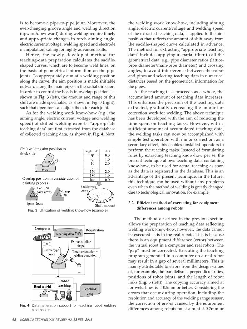
is to become a pipe-to-pipe joint. Moreover, the ever-changing groove angle and welding direction (upward/downward) during welding require timely and appropriate changes in torch-aiming angle, electric current/voltage, welding speed and electrode manipulation, calling for highly advanced skills. Hence, the newly developed method for teaching-data preparation calculates the saddle-shaped curves, which are to become weld lines, on the basis of geometrical information on the pipe joints. To appropriately aim at a welding position along the curve, the aim position is made shiftable outward along the main pipes in the radial direction. In order to control the beads in overlap positions as shown in Fig. 3 (left), the amount and range of this shift are made specifiable, as shown in Fig. 3 (right), such that operators can adjust them for each joint. As for the welding work know-how (e.g., the aiming angle, electric current, voltage and welding speed) of skilled welding experts, "appropriate teaching data" are first extracted from the database of collected teaching data, as shown in Fig. 4. Next,
the welding work know-how, including aiming angle, electric current/voltage and welding speed of the extracted teaching data, is applied to the aim position that reflects the amount of shift away from the saddle-shaped curve calculated in advance. The method for extracting "appropriate teaching data" includes applying a spatial filter to all the geometrical data, e.g., pipe diameter ratios (lattice-pipe diameter/main-pipe diameter) and crossing angles, to avoid interference between the robot and pipes and selecting teaching data in numerical distances based on the geometrical information for the pipes. As the teaching task proceeds as a whole, the accumulated amount of teaching data increases. This enhances the precision of the teaching data extracted, gradually decreasing the amount of correction work for welding. The above technique has been developed with the aim of reducing the time spent on teaching tasks. However, with a sufficient amount of accumulated teaching data, the welding tasks can now be accomplished with simple test operation with minor correction; as a secondary effect, this enables unskilled operators to perform the teaching tasks. Instead of formulating rules by extracting teaching know-how per se, the present technique allows teaching data, containing know-how, to be used for actual teaching as soon as the data is registered in the database. This is an advantage of the present technique. In the future, this technique can be used without any problems even when the method of welding is greatly changed due to technological innovation, for example.
2.2 Efficientmethodofcorrectingforequipment differences among robots
The method described in the previous section allows the preparation of teaching data reflecting welding work know-how, however, the data cannot be executed as-is in the real robots. This is because there is an equipment difference (error) between the virtual robot in a computer and real robots. The "gap" must be corrected. Executing the teaching program generated in a computer on a real robot may result in a gap of several millimeters. This is mainly attributable to errors from the design values of, for example, the parallelisms, perpendicularities, positions of robot joints, and the length of robot links (Fig. 5 (left)). The copying accuracy aimed at for weld lines is ±0.5mm or better. Considering the errors that occur during operation, including the resolution and accuracy of the welding range sensor, the correction of errors caused by the equipment differences among robots must aim at ±0.2mm or
Fig. 3 Utilization of welding know-how (example)
Fig. 4 Data-generation support for teaching robot welding pipe booms
KOBELCO TECHNOLOGY REVIEW NO. 33 FEB. 201563
better. One of the methods for correcting for the equipment differences among robots includes deriving link parameters, i.e., an error factor of robot joints as described above. However, since there are other error factors (e.g., deflection of the link due to gravity and gear backlash) that cannot be accounted for by the link parameters, it is difficult to reduce the robot tip error to 1mm or smaller while the position and posture are being changed in the space range of robot motion. Accordingly, in order to achieve an accuracy of ±0.2mm, it is more realistic to use a method of correction by directly measuring the error for each position and posture. It is not realistic to measure errors for the motion space of a robot with 6 degrees of freedom. Hence, the equipment was reviewed, from its planning and designing stage, so that the welded part of each pipe always stays in the same position when viewed from the robot. The motion range of the robot during pipe welding was thereby restricted. The rotation angle around the welding torch is a posture angle that does not affect the welding operation. Therefore, this rotation angle was set at a predetermined value to decrease the degrees of freedom for the posture angles whose errors are to be measured. Accordingly, the errors were measured in a space that restricts the range of positions and postures that can be taken during pipe welding. The measurement method includes setting up three dial gauges arranged in directions orthogonal to each other, as shown in Fig. 5 (right), and attaching a spherical measurement probe to the tip of the robot, thereby measuring the size of the gap at the tip due to the change of posture in the 2 degrees of freedom (i.e., the angle of incidence and horizontal angle in a polar coordinate system with the pole at the probe tip). This measurement was conducted at the 8 corners of a cuboidal space (front to back; 50mm×left to right; 100mm×top to bottom; 30mm) that can roughly enclose the saddle-shaped curve of
a maximum-sized pipe (Fig. 6). The errors measured in this space were used to correct the tip position. The results are shown in Fig. 6 (bottom). The results indicate that the errors can be corrected to 0.2mm or better in all the x, y, z directions, as originally aimed at. The teaching data, prepared in accordance with the above method, were thus corrected to achieve the target correction accuracy. This, as a result, eliminated the need for correcting for errors in the prepared teaching data, the errors that were due to differences among the machines. Moreover, the operation orbit of a robot can now be verified by a simple operation check. Thus, the time for correcting teaching data for real machines has been successfully and significantly reduced.
3. Technology for detecting welding positions compatible with mirror-surfaced works and weaving
Top and bottom booms are unique in that they have pipe-to-plate and plate-to-plate joints. This poses a problem: Irradiating a laser beam from a range sensor onto mirror-finished groove surfaces causes multiple reflections, which destabilize the detection of the welding position. An optical arrangement was specified to enable a separation between the normal light-section line and multi-reflected lights, which was reflected in the design of a sensor. Meanwhile, an image processing technique was developed for extracting the normal light-section line while taking into account its continuity. This has led to the development of a technology for detecting welding positions, which allows stable measurement of the groove shape.
Fig. 5 Measuring equipment difference of robot
Fig. 6 Measuring change of torch angle before and after error correction
KOBELCO TECHNOLOGY REVIEW NO. 33 FEB. 2015 64
3.1 Range sensor compatible with multiple reflectionoflaserbeam
Fig. 7 depicts a range sensor for V-groove welding. The sensor includes a CCD camera and laser unit, both attached to the tip of the arm of the welding robot. A light is irradiated onto a groove joint for light sectioning. The photo images taken by the camera are used for measuring the distance from the groove joint and for determining the joint shape, on the basis of the triangulation principle. The sensor recognizes the weld line, and copy welding is performed while making corrections to the pre-taught positions. As shown in Fig. 8 (1), no multiple reflection occurs on diffusing surfaces, or on surfaces that cause diffused reflection, e.g., rust and paint; so only the clear image of the regular light-section line is left. On the other hand, as shown in Fig. 8 (2), a mirror surface, which, due to machining or for some other reason, causes specular reflection of light, causes multiple reflection of the laser beam, making it difficult to separate the regular light-section lines. As described, the plate-plate joints, found in top and bottom booms, cause mixing of the regular light-section lines to be detected with multiple reflection components, making it difficult to stably detect the
positions of weld lines. A typical range sensor that is commercially available for welding extracts a regular light-section line by devising its optical filters and image processing, but its detection capability is limited. It is against this background that Kobe Steel developed a welding range sensor incorporating a unique technique for detecting the positions of weld lines.
3.1.1 Image simulation of light-section line
Fig. 9 shows the configuration of a welding range sensor. As shown in this figure, a camera and a laser unit are disposed on a plane determined by two lines, i.e., a bisector line of the groove angleθ (θ= 90 degrees for fillet weld joint) and the weld line. A laser slit beam is irradiated perpendicularly to the weld line. Here, the laser projection angle is designated as α, and the camera angle as β. When both welded members have diffusing surfaces, there is no multiple reflection of the laser slit beam. As a result, the image taken by the camera is as shown in Fig.10 (1). When one welded member has a diffusing surface and the other has a specular reflection surface, two laser slits appear, as shown in Fig.10 (2), due to multiple reflection (secondary reflection). One of the two is a laser slit beam A', which is the reflection of the laser slit beam A on the specular surface of the welded member B. Since this laser slit beam A' is an image of the laser slit beam A reflected from the mirror surface, the position of laser slit beam A' depends on the position from which it is viewed, or on the position of the camera. The other is laser slit beam B", which is caused by laser slit beam B specularly reflected on the mirror surface of the welded member B and is irradiated onto a diffusing surface of welded member A. Since this laser slit beam B" is diffusely reflected by the welded member
Fig. 8 Light-section images (examples)
Fig. 7 Welding robot with range sensor
Fig. 9 Configuration of range sensor for welding
KOBELCO TECHNOLOGY REVIEW NO. 33 FEB. 201565
A, its visual position does not change, regardless of the camera position. Next, when both welded members have mirror surfaces, four laser slit beams appear as a result of secondary reflection, as shown in Fig.10 (3). These are, namely, laser slit beams A' and B', reflected on the mirror surfaces of welded members, and laser slit beams A" and B", specularly reflected on the mirror surfaces. The photos (1), (2) and (3) of Fig.10 show the view from a camera angleβ. Increasing the camera angleβ reverses the positions of "slit beam A and slit beam B" and "slit beam A' and slit B'." Fig.10 (4) shows a view of the reversed positions. As described, when a welding range sensor is disposed with a laser projection angleα and camera angleβ against a welded joint with a groove angleθ, light-section lines captured by a camera, the lines including secondary reflection, can be calculated by simulation. Assumingθ to be 50 degrees andα to be 60 degrees, the relationship between the camera angleβ and apparent angleγ from the center of the image is graphed in Fig.11 (top). Separating the true light-section line, plotted in red in the graph, from the reflection of multiple-reflection components shown in green and blue, which are inseparable, is difficult for a camera disposed at an angle of, say,β= 70 degrees. Moreover, the camera angleβ cannot be made smaller, due to the downsizing of the casing and the restrictions imposed by equipment such as the welding torch. In other words, the optimum camera angleβ, for ease in separating the true light-section line and for downsizing the range sensor, is found to be 80 degrees. Kobe Steel has limited the groove angleθ of interest to approximately 50
degrees and thereby found an arrangement that facilitates the separation between the true light-section line and multiple reflection components in an image. That is, limiting the joints of interest enables us to determine the position of the sensor in which laser multiple reflection is unlikely to occur. This arrangement was used for designing a welding range sensor that enabled the stable detection of weld-line positions even on mirror surfaces.
3.2 Measures against contamination of protective window for sensors
High-current welding generates a large amount of spatter (metal spattered during welding) and fume (metal vapor). This contaminates the sensor-protecting windows through which the laser beam is irradiated and received. Thus the windows must be replaced periodically. Frequent replacement of
Fig.11 Appearance change of image in light-section method
Fig.10 Appearance of secondary reflection image
KOBELCO TECHNOLOGY REVIEW NO. 33 FEB. 2015 66
the protective windows imposes a significant burden on field workers. Since the level of contamination depends on the material of the protective windows, quartz glass, acrylic plate and polycarbonate were used here for the materials of a protective window, so as to compare the level of contamination. Welding was performed for 50 min with a welding current of 250A. The resulting levels of contamination on the protective windows are shown in Fig.12 (1). Polycarbonate was found to result in relatively small amount of adhered contamination. In addition, the light shielding plate was extended such that neither welding-arc light nor spatter directly hit the protective window. The light-shielding plate was also designed to prevent it from interfering with the pipes in narrow spaces. Fig.12 (2) shows the improved design. As shown in (2), the protective window results in almost no contamination.
3.3 Techniquecompatiblewithweavingfor detecting light-section line
When the camera in a range sensor takes the image of welding that generates spatters (Fig.13 (1)), the spatters, with their high brightness, also appear in the image along with the light-section line of the laser beam. This makes the separation of the light-section line from spatter difficult, posing a problem in stable shape measurement (Fig.13 (2)). In captured images, the spatters move faster than the light-
section lines. Therefore, in a method for reducing erroneous detection caused by spatter, the focus was placed on the change in brightness in chronological images. When there are K pieces of continuous images chronologically captured by a camera, the brightness of the images is designated as Image1(i, j),…, ImageK(i, j). Here, i and j represent the coordinates of the image (size: M×N pixels). The average brightness, Image0(i, j), of the K pieces of images is given by Equation (1). Image0(i, j)=(Image1(i, j)+…+ImageK(i, j)) / K … (1) Averaging the brightness of the chronological images decreases the brightness of the spatter that moves faster. On the other hand, assuming that the shape of the welded joint does not change significantly, the brightness of the light-section line irradiated remains the same even after the averaging. Thus a decision was made to extract the light-section line using Image0(i, j) generated. Fig.14 schematically illustrates a case where K = 3. When averaging the brightness of images, however, the swinging motion of the sensor, as in weaving, causes the image of the light-section line to blur, causing a problem in stable detection; so focus was placed on the fact that the direction of flying spatters crosses the weaving direction orthogonally. Captured images that swing between left and right during weaving welding were compared in the weaving direction. This resulted in the development of a technique for detecting welding position that allows a more stable measurement of groove shape. The image comparison was based on the sum of absolute difference (SAD), which represents the degree of similarity among the images. Taking Image1(i, j) as a reference, the SADs of the chronological images, Image2(i, j), …, ImageK(i, j), are expressed as follows.
Fig.13 Spatter and fume during weldingFig.14 Welding-posit ion-detection logic in spatter
environment
Fig.12 Dirt protection by protective window
KOBELCO TECHNOLOGY REVIEW NO. 33 FEB. 201567
… (2)
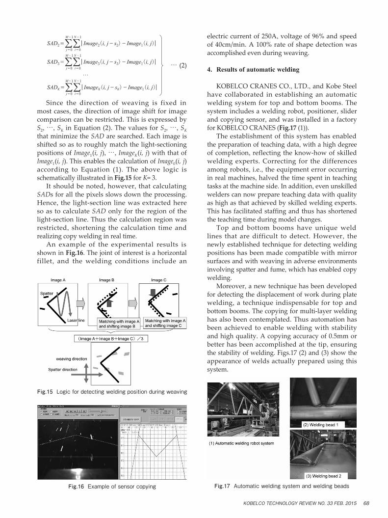
Since the direction of weaving is fixed in most cases, the direction of image shift for image comparison can be restricted. This is expressed by S2, …, SK in Equation (2). The values for S2, …, SK that minimize the SAD are searched. Each image is shifted so as to roughly match the light-sectioning positions of Image1(i, j), …, ImageK(i, j) with that of Image1(i, j). This enables the calculation of Image0(i, j) according to Equation (1). The above logic is schematically illustrated in Fig.15 for K= 3. It should be noted, however, that calculating SADs for all the pixels slows down the processing. Hence, the light-section line was extracted here so as to calculate SAD only for the region of the light-section line. Thus the calculation region was restricted, shortening the calculation time and realizing copy welding in real time. An example of the experimental results is shown in Fig.16. The joint of interest is a horizontal fillet, and the welding conditions include an
electric current of 250A, voltage of 96% and speed of 40cm/min. A 100% rate of shape detection was accomplished even during weaving.
4. Results of automatic welding
KOBELCO CRANES CO., LTD., and Kobe Steel have collaborated in establishing an automatic welding system for top and bottom booms. The system includes a welding robot, positioner, slider and copying sensor, and was installed in a factory for KOBELCO CRANES (Fig.17 (1)). The establishment of this system has enabled the preparation of teaching data, with a high degree of completion, reflecting the know-how of skilled welding experts. Correcting for the differences among robots, i.e., the equipment error occurring in real machines, halved the time spent in teaching tasks at the machine side. In addition, even unskilled welders can now prepare teaching data with quality as high as that achieved by skilled welding experts. This has facilitated staffing and thus has shortened the teaching time during model changes. Top and bottom booms have unique weld lines that are difficult to detect. However, the newly established technique for detecting welding positions has been made compatible with mirror surfaces and with weaving in adverse environments involving spatter and fume, which has enabled copy welding. Moreover, a new technique has been developed for detecting the displacement of work during plate welding, a technique indispensable for top and bottom booms. The copying for multi-layer welding has also been contemplated. Thus automation has been achieved to enable welding with stability and high quality. A copying accuracy of 0.5mm or better has been accomplished at the tip, ensuring the stability of welding. Figs.17 (2) and (3) show the appearance of welds actually prepared using this system.
SAD2=ΣΣ|Image2(i, j-s2)-Image1(i, j)|j=0 i=0
M-1 N-1
SAD3=ΣΣ|Image3(i, j-s3)-Image1(i, j)|j=0 i=0
M-1 N-1
SADK=ΣΣ|ImageK(i, j-sK)-Image1(i, j)|j=0 i=0
M-1 N-1…
Fig.15 Logic for detecting welding position during weaving
Fig.16 Example of sensor copying Fig.17 Automatic welding system and welding beads
KOBELCO TECHNOLOGY REVIEW NO. 33 FEB. 2015 68
Conclusions
Automation has been achieved for welding top and bottom booms, which will reduce the man-hours spent in teaching even when a model change is needed for pipe booms in the future. It also has enabled a vertical ramp-up of production lines. Further, in our overseas factories, the future increase in production volumes can be processed by automatic welding, rather than by skilled welding experts, by providing the core technology for welding automation in a black box. This technology will contribute to the establishment of a production
system that can respond quickly and appropriately to overseas demand, while contributing to the quality improvement of welding.
References
1) M. Hida et al. R&D Kobe Steel Engineering Reports. 2007, Vol.57, No.1, pp.86-89.
2) M. Hida et al. Proceedings for the 22nd annual conference of the robotics society of Japan. The Robotics Society of Japan, 2004, p.227.
3) M. Hida et al. Welding Technology, September 2009. Sanpo Publication.
4) T. Yamashita et al. R&D Kobe Steel Engineering Reports. 2012, Vol.62, No.1, pp.87-90.